- Table of Contents
- Related Documents
-
| Title | Size | Download |
|---|---|---|
| 01-Text | 2.40 MB |
Examining the installation site
Temperature and humidity requirements
Grounding and lightning protection
Installing the AP by using the installation holes at both AP sides
Attaching the AP bracket to the AP
Mounting the AP on a vertical pole
Mounting the AP on a horizontal pole
Connecting the grounding cable
Connecting the AP to the network
3 Appendix A Technical specifications
5 Appendix C Transceiver modules
Transceiver module specifications
1 Preparing for installation
|
|
WARNING! Install the AP under the guidance of technical engineers and read this chapter carefully before installation. |
Examining the installation site
Examine the installation site before installation to ensure that the AP will work in a good environment.
Installation site selection
The installation site must be selected according to the network planning and technical requirements of telecommunications equipment, with factors such as climate, hydrology, geology, earthquake, electric power, and transportation taken into consideration.
Determine the installation location by observing the following principles:
· The AP will not be exposed to high temperature, dust, harmful gases, electromagnetic interference sources (high power radars, radio stations, or electrical substations), unstable voltage, heavy vibration, and loud noise.
· The location is not water seeping, water soaking, and condensing.
· The location is away from inflammable and explosive substances.
Temperature and humidity requirements
Table1-1 Temperature and humidity requirements
|
Item |
Specification |
|
Operating temperature |
–40°C to +65°C (–40°F to +149°F) |
|
Storage temperature |
–40°C to +85°C (–40°F to +185°F) |
|
Operating humidity |
0% RH to 100% RH, noncondensing |
|
Protection class |
IP67 |
Power supply
Power the AP by using the provided power cord. See "Connecting the power cord" for the connection method.
Grounding and lightning protection
The AP must be reliably grounded. Make sure the grounding points of the grounding conductor of the AP, lightning arresters, PE wire of the power cord, and antenna support are separate from each other, make good contact, and are securely connected and treated with corrosion protection.
Ground resistance
The ground resistance is typically required to be less than 5 ohms, and less than 10 ohms in an area with less than 20 thunderstorm days a year. For a piece of angle steel buried in the earth as a grounding conductor, the ground resistance is required to be less than 10 ohms. In an area with a higher ground resistance, reduce the ground resistance by using brine or resistance reducing agent around the grounding conductor.
The top of the grounding conductor must be a minimum of 0.7 m (2.30 ft) away from the ground surface. In cold areas, the grounding conductor must be buried below the frozen soil layer.
Grounding conductor
If a grounding strip is available, connect the yellow and green grounding cable to the grounding strip. To make a grounding cable, make sure the cable has a cross-section area of a minimum of 6 mm2 (0.01 in2) and a length of no longer than 3 m (9.84 ft).
If no grounding strip is available, bury a piece of angle steel/steel tube a minimum of 0.5 m (1.64 ft) long in the earth to act as the grounding conductor. It must be zinc-plated. In the case of a piece of angle steel, the size must be a minimum of 50 × 50 × 5 mm (1.97 × 1.97 × 0.20 in). In the case of a piece of steel tube, it must have a wall thickness of a minimum of 3.5 mm (0.14 in). Weld the grounding cable of the AP onto the grounding conductor and use anti-erosion treatment on the welding joint. With a cross-section area of a minimum of 6 mm2 (0.01 in2), the grounding cable must be as short as possible and must not be coiled.
Make sure the grounding terminals of all the lightning arresters of the AP and the peer device of the AP are reliably grounded.
Ground lead
A ground lead is a metal conductor connecting a grounding net and a grounding strip. The grounding cable of the AP must be connected to the grounding strip. The ground lead must be 30 m (98.43 ft) or shorter. A piece of zinc-coated flat steel with a cross-section area of 40 × 4 mm (1.57 × 0.16 in) or 50 × 5 mm (1.97 × 0.20 in) is recommended. Connect the grounding strip and the ground lead of the AP through the yellow and green grounding cable with an area of 35 mm2 (0.05 in2), or weld them directly. Use anti-erosion treatment on the welding joint.
Power grounding (AC)
Use a power cord with a protective earth (PE). Do not use a power cord with only an L line and an N line.
The neutral line of the power cord must not be connected with the PGND of other communications equipment. The L and N lines cannot be connected.
Lightning rod
The lightning protection grounding (for example, the grounding of the lightning rod) must be connected to the grounding conductor of the equipment room.
The lightning rod must be tall enough to protect the AP and its antennas.
In plain areas, the shielding angle of the lightning rod must be less than 45 degrees. In mountainous areas or lightning areas, the shielding angle must be less than 30 degrees.
Ethernet cable
Use a shielded twisted pair cable for outdoor installation. Make sure the devices at the two ends of the cable are reliably grounded.
If a metal tube is used, make sure the Ethernet cable is reliably grounded at both ends of the tube.
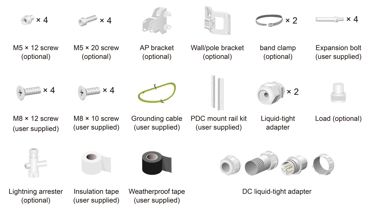
Installation accessories
Figure1-1 Installation accessories
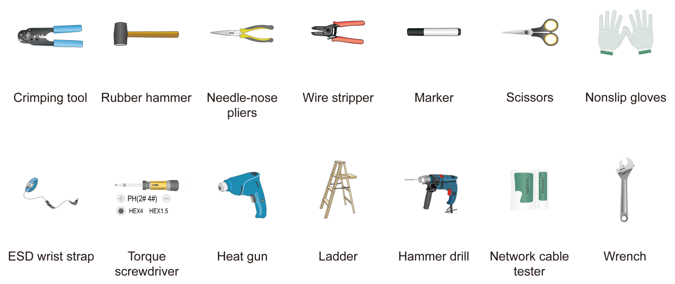
Installation tools
When installing the AP, you might need the following tools. Prepare the installation tools yourself as required.
Figure1-2 Installation tools
2 Installing the AP
|
|
WARNING! The AP is large and heavy. Avoid bodily injury and device damage during the installation. |
Pre-installation tasks
Before installing an AP, perform the following tasks:
· Connect the AP to the power source and the network. Examine the LED to verify that the AP can operate correctly. For more information about the AP LED, see "Appendix B LEDs and Ports."
· Verify that cabling at the installation site has been completed.
· Record the AP MAC address and serial number marked on the rear of the AP for future use.
Before connecting cables to the AP, read the following guidelines carefully:
· Route cables according to the cabling design.
· Arrange cables firmly and neatly without crossing, twisting, or cracking them.
· Do not route cables together with high-voltage electric power pipelines, fire-fighting pipes, or lightning protection cables to avoid the electromagnetic interference.
· Use PVC pipes, iron pipes, Plica tube, or cable troughs for cable routing. Route cable pipes and troughs neatly against the wall and connect them through hoses or pipe joints at the bend. Secure cable pipes and troughs by using cable ties or angle steels at the spacing of 1 m (3.28 ft) to 1.5 m (4.92 ft) and ground the two ends in the case of metal tubes.
· When you route PVC pipes outdoors in a horizontal way, cut an opening at the bottom of the PVC pipes every 6 m (19.69 ft) to avoid water accumulation.
· Seal the holes for routing cables in the wall with waterproof and flame retardant material.
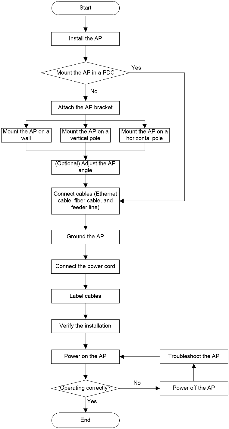
Installation flowchart
Figure2-1 Installation flowchart
Installing the AP
Installing the AP by using the installation holes at both AP sides
|
|
IMPORTANT: Do not open the vent valve. |
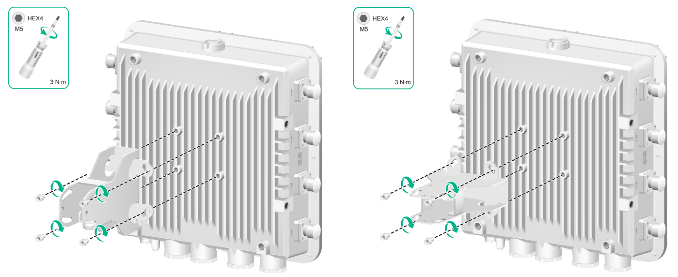
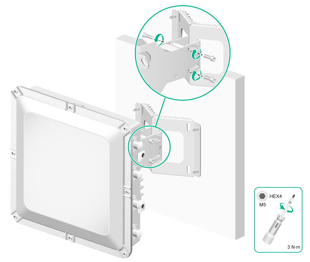
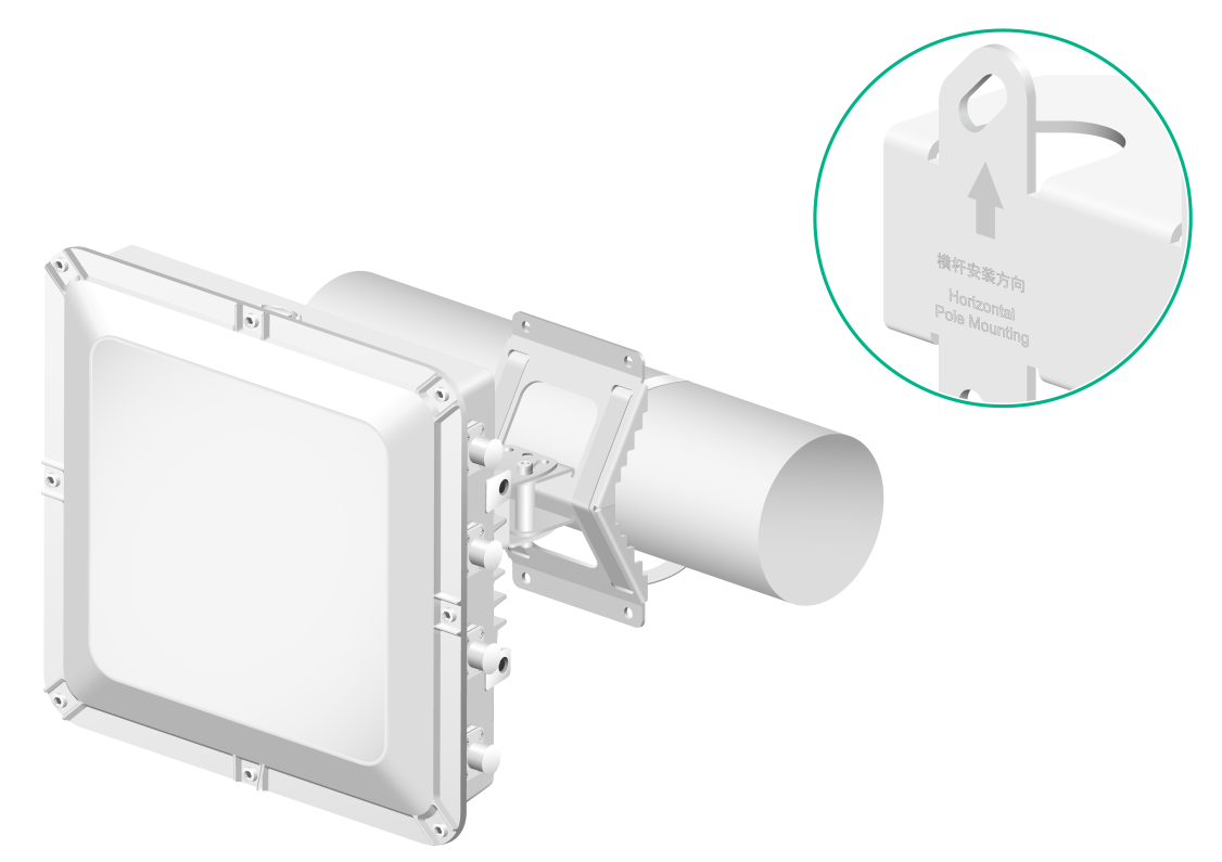
Attaching the AP bracket to the AP
This procedure is required only for wall mounting and pole mounting.
Align the AP bracket with the screw holes on the rear of the AP, and then use M5 × 12 screws to attach the AP bracket to the AP.
|
|
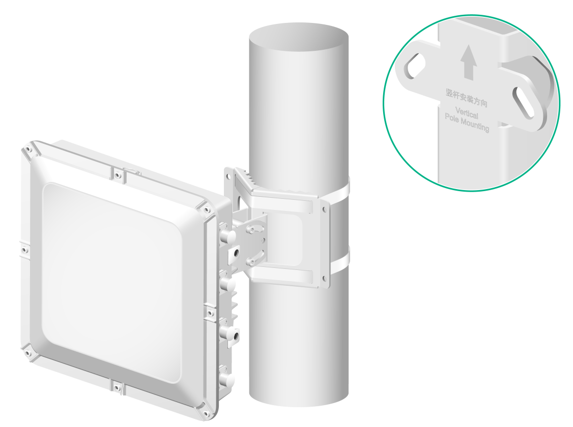
NOTE: The AP bracket supports both horizontal and vertical installations. · To mount the AP on a vertical pole, make sure the vertical pole mounting arrow on the AP bracket points up. To mount the AP on a horizontal pole, make sure the horizontal pole mounting arrow on the AP bracket points up. · To mount the AP on a wall, you can orient the AP bracket horizontally or vertically as required. |
Figure2-2 Attaching the AP bracket to the AP
Mounting the AP in a PDC
You can mount the AP in a power distribution cabinet (PDC) by using the mounting holes in the AP rear or at AP sides.
To use the mounting holes at AP sides, attach the AP bracket as shown in Figure2-3 to the AP.
To use the four mounting holes in the rear, prepare a mounting bracket and M8 × 10 screws yourself.
AP brackets and AP installation holes
Figure2-3 AP brackets for installation in a PDC
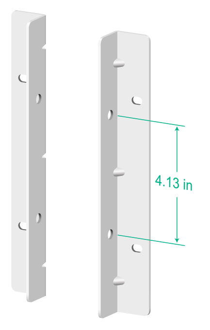
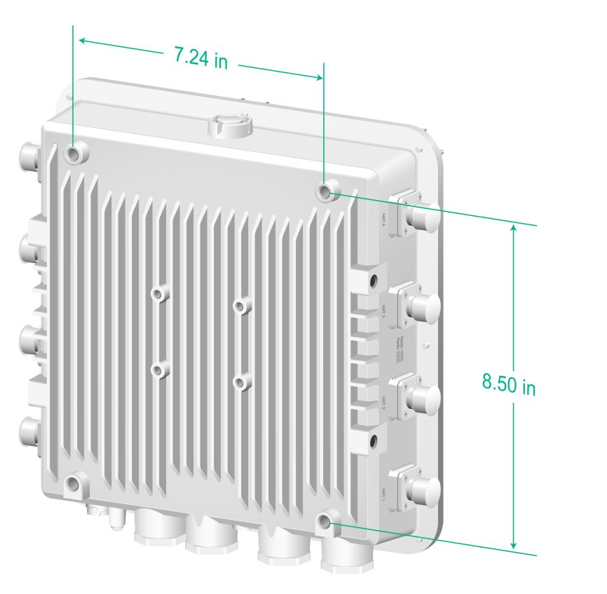
Figure2-4 Installation holes in the AP rear
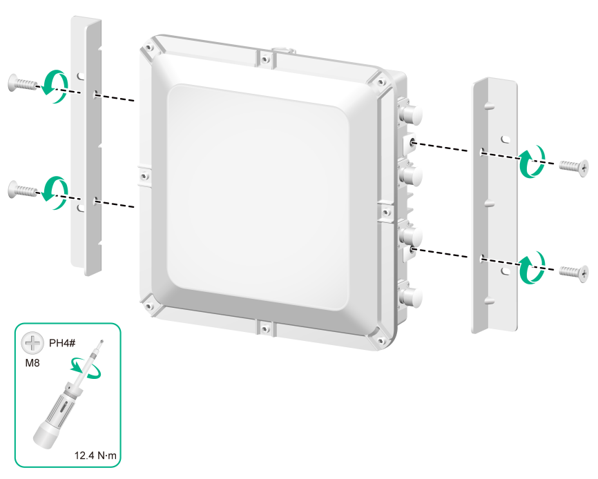
Attaching the AP brackets to the AP
Attach the AP brackets to the AP. Align the screw holes in the AP brackets with the installation holes at the AP sides, and use M8 screws to attach the AP brackets to the AP. Tighten the screw to a torque value of 12.4 Nm.
Figure2-5 Attaching the AP brackets to the AP
Mounting the AP on a wall
The following procedure mounts the AP on a wall with the vertical pole mounting arrow on the AP bracket pointing up. To mount the AP on a wall with the horizontal pole mounting arrow on the AP bracket pointing up, adjust the installation direction of the wall/pole bracket accordingly.
To mount the AP on a wall:
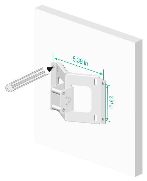
1. Use the wall/pole bracket to mark four installation holes on the wall.
Figure2-6 Marking the installation holes
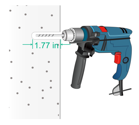
2. Use a hammer drill to drill holes with a diameter of 8 mm (0.32 in) at the marked locations, as shown in Figure2-7.
Figure2-7 Drilling holes in the wall
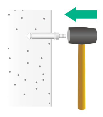
3. Insert an expansion bolt into each hole, and tap the bolt with a rubber hammer until the expansion sleeve is flush with the wall surface, as shown in Figure2-8.
Figure2-8 Hammering an expansion bolt into a hole
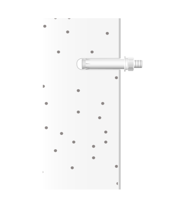
4. Fasten the nut on each expansion bolt to expand the expansion sleeve.
Figure2-9 Fastening the nut on an expansion bolt
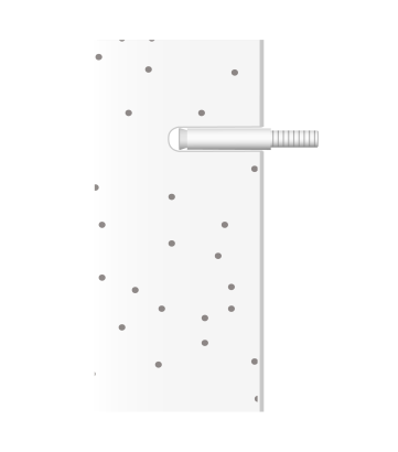
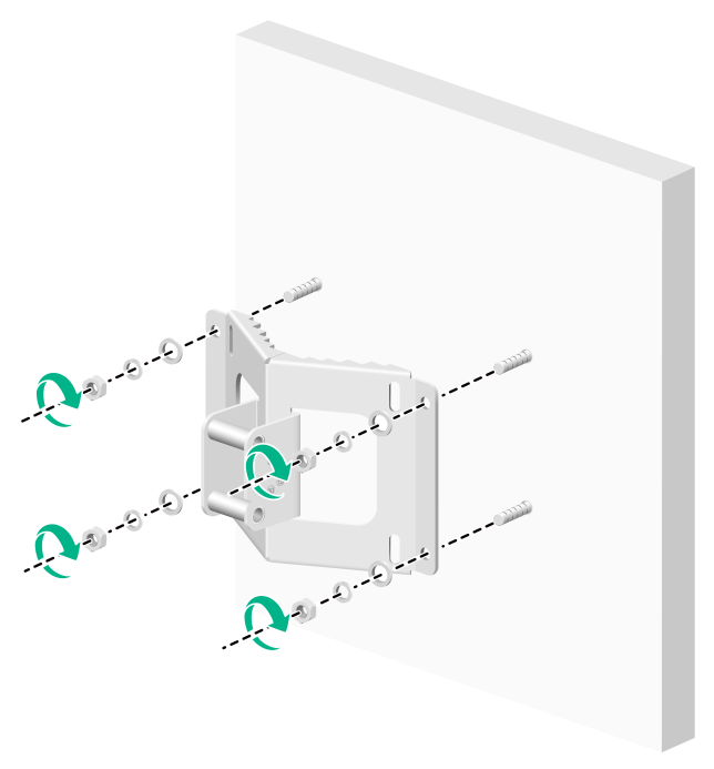
5. Remove the nut and washers from each bolt.
Figure2-10 Removing the nut from an expansion bolt
6. Align the installation holes on the wall/pole bracket with the bolts on the wall, and then fasten the nuts and washers on the expansion bolts to secure the wall/pole bracket to the wall.
Figure2-11 Attaching the wall/pole bracket to the wall
7. Orient the AP with the vertical pole mounting arrow on the AP bracket pointing up. Use M5 × 20 screws to secure the AP bracket attached to the AP to the wall/pole bracket.
Figure2-12 Attaching the AP to the wall/pole bracket
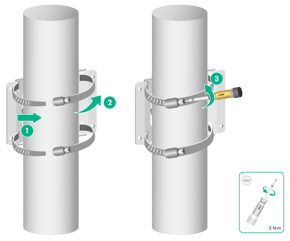
Mounting the AP on a vertical pole
The optional band clamps support poles with a diameter of 60 to 80 mm (2.36 to 3.15 in). If the diameter of the pole is not in the range, prepare band clamps yourself.
To mount the AP on a vertical pole:
1. Use band clamps to secure the wall/pole bracket to the vertical pole.
Figure2-13 Securing the wall/pole bracket to the vertical pole
2. Orient the AP with the vertical pole mounting arrow on the AP bracket pointing up. Use M5 × 20 screws to secure the AP bracket attached to the AP to the wall/pole bracket.
Figure2-14 Attaching the AP to the wall/pole bracket
Mounting the AP on a horizontal pole
1. Use band clamps to secure the wall/pole bracket to the horizontal pole.
Figure2-15 Securing the wall/pole bracket to the horizontal pole
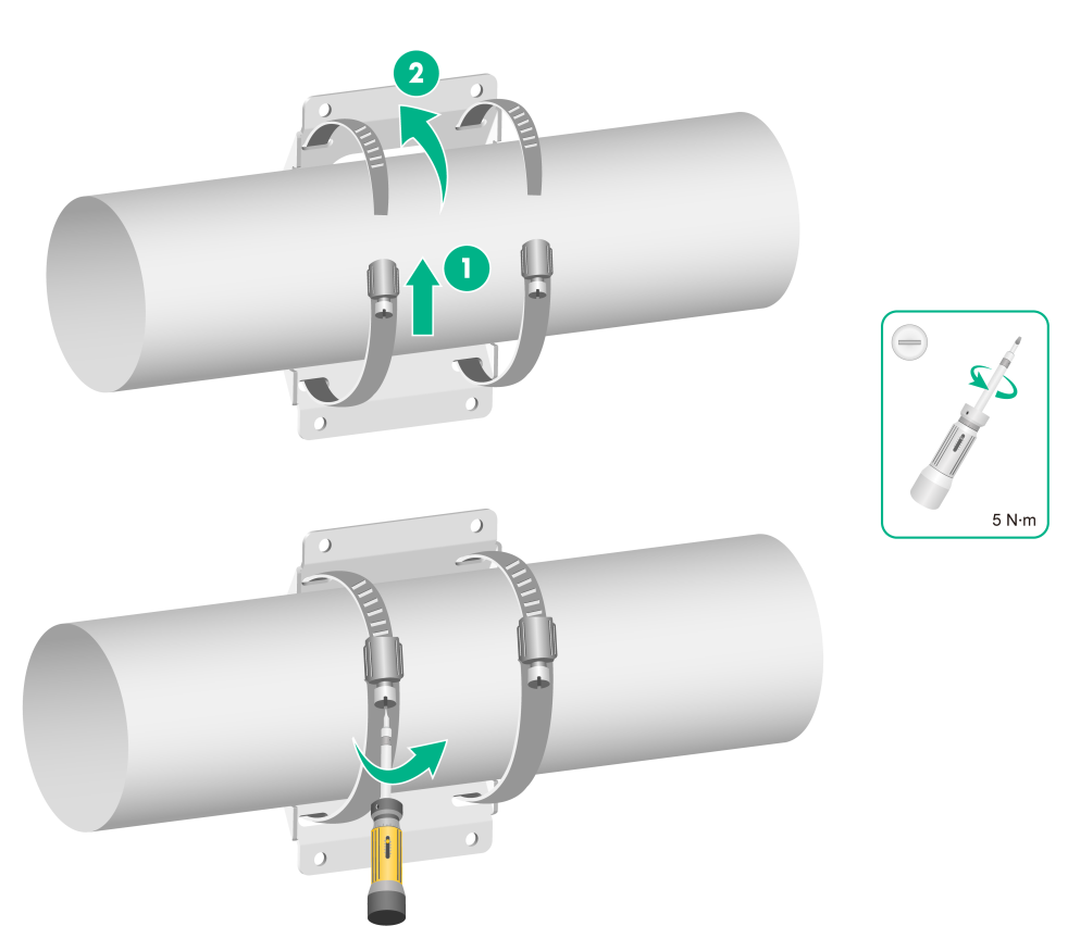
2. Orient the AP with the vertical pole mounting arrow on the AP bracket pointing up. Use M5 × 20 screws to secure the AP bracket attached to the AP to the wall/pole bracket.
Figure2-16 Attaching the AP to the wall/pole bracket
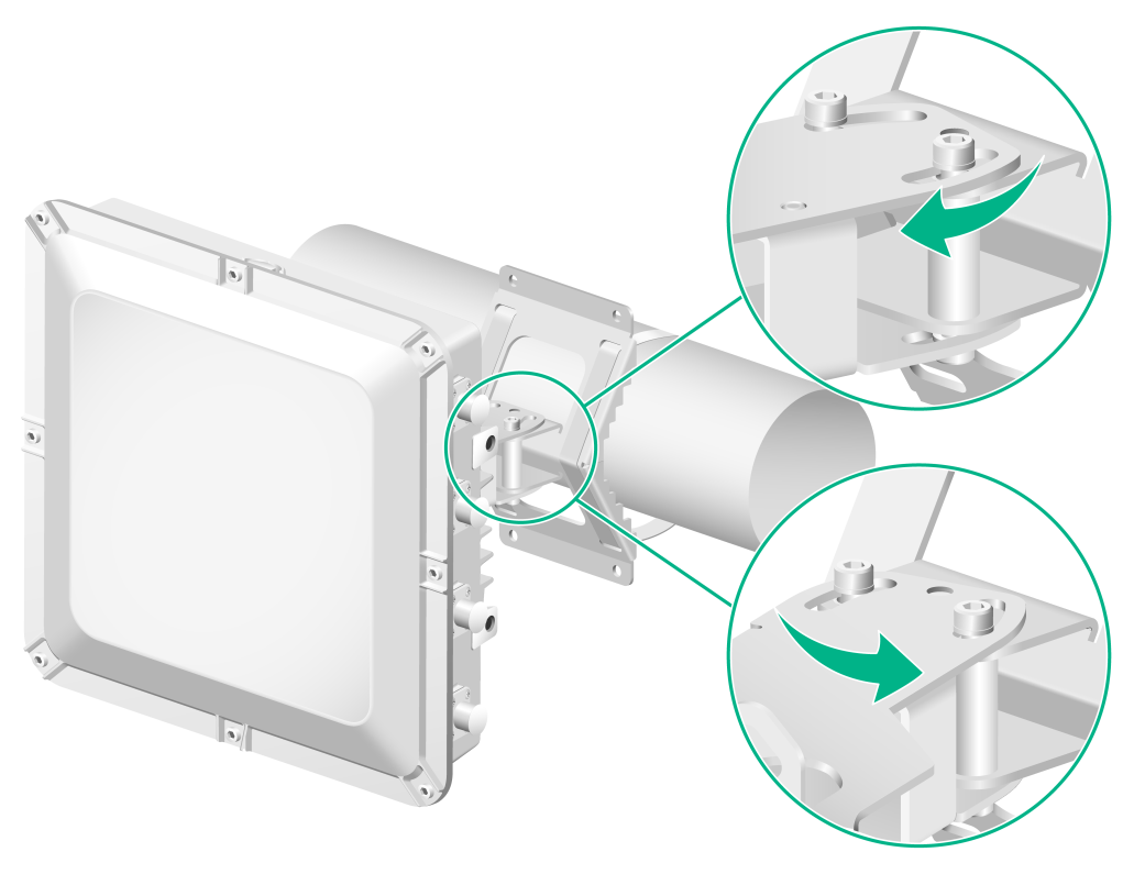
Adjusting the AP angle
After the AP is installed, you can adjust the AP angle by loosening the four screws that secure the AP bracket and wall/pole bracket.
· If the AP is installed with the vertical pole mounting arrow on the AP bracket pointing up, you can adjust the AP to the desired elevation angle (the adjustment angle must not exceed 60 degrees).
· If the AP is installed with the horizontal pole mounting arrow on the AP bracket pointing up, you can adjust the AP to the desired azimuth angle (the adjustment angle must not exceed 60 degrees).
Figure2-17 Adjusting the AP angle on a vertical pole
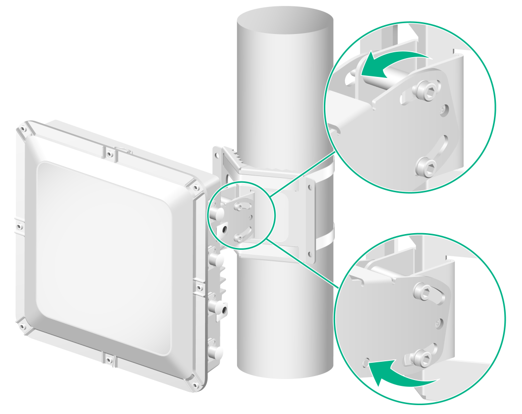
Figure2-18 Adjusting the AP angle on a horizontal pole
Connecting cables
|
|
NOTE: When you apply weatherproof tape to a cable connection, follow these restrictions and guidelines: · Make sure you attach the adhesive side of the tape to the cable connector. · Pull the tape as needed for overlap. · Start wrapping at the top of the connector, and overlap the tape to half-width. Avoid creases or wrinkles and press the tape against the connection so that there are no gaps. Smooth each wrapped layer with your hands to ensure full adhesion. · To prevent device damage, attach weatherproof caps tightly to connectors that are not in use. |
Connecting an Ethernet cable
Use Category-5e or above Ethernet cables only. As a best practice, use shielded twisted pair (STP) cables.
To connect an Ethernet cable:
1. Disassemble the weatherproof connector and sealing nut, and then feed the cable through the connector.
Figure2-19 Disassembling the weatherproof connector and sealing nut
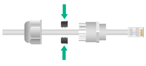
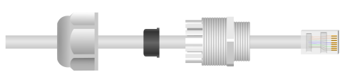
2. Attach the split sealing washer to the cable, connect the Ethernet cable to the target port on the AP, and insert the sealing washer into the weatherproof connector.
Figure2-20 Connecting an Ethernet cable
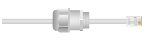
3. Use a wrench or wear nonslip gloves to fasten the sealing nut and the weatherproof connector.
Figure2-21 Fastening the sealing nut and weatherproof connector
4. Start wrapping at the top of the connector. Smooth the tape edges to ensure full adhesion.
Figure2-22 Wrapping the connector
Connecting a fiber cable
|
|
WARNING! · To avoid cable damage, do not pull the fiber cable with excessive force. · To avoid affecting fiber performance, make sure the fiber cable is not bended or folded when fastening the sealing nut. |
|
|
IMPORTANT: · Before connecting a fiber cable, remove the dust caps from the fiber connectors. · To use a fiber pigtail that does not have any protective sleeve, first use weatherproof tape to wrap the fiber pigtail before you connect the fiber pigtail. |
To connect a fiber cable:
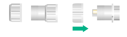
1. Use weatherproof tape to start wrapping below the fiber connector, build up the fiber cable diameter near the opening in the split sealing washer. Smooth the tape edges to ensure full adhesion.
Figure2-23 Wrapping the fiber cable
![]()
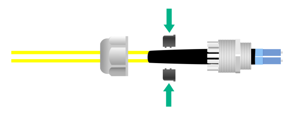
2. Disassemble the weatherproof connector and sealing nut, feed the cable through the connector, and then attach the split sealing washer to the cable.
Figure2-24 Feeding the cable through the weatherproof connector
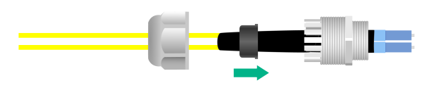
3. Insert the sealing washer into the weatherproof connector.
Figure2-25 Inserting the sealing washer into the weatherproof connector
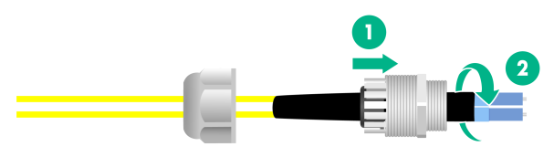
4. Attach a transceiver module to the SFP connector, and then connect the fiber cable to the transceiver module.
Figure2-26 Connecting a fiber cable

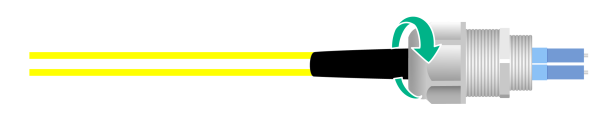
5. Adjust the weatherproof connector to ensure that the fiber is not bended or folded, and then fasten the weatherproof connector.
Figure2-27 Fastening the weatherproof connector
6. Use a wrench or wear nonslip gloves to fasten the sealing nut.
Figure2-28 Fastening the sealing nut
7. Start wrapping at the top of the weatherproof connector until the entire connector is wrapped. Smooth the tape edges to ensure full adhesion.
Figure2-29 Wrapping the weatherproof connector
Connecting an RF cable
|
|
WARNING! To avoid device damage or bodily injury caused by excessive radiation exposure, make sure the antennas and RF cables comply with local regulations. As a best practice, purchase H3C recommended antennas and RF cables. To ensure correct operation of the AP, make sure the antennas and RF cables meet the following basic requirements: · The VSWR for RF cables is less than or equal to 1.4. · The VSWR for antennas is less than or equal to 1.8. · The maximum gain can ensure that the AP's EIRP complies with local regulations. |
|
|
CAUTION: · Make sure the AP is grounded reliably. · VSWR tests are required for RF load joints and other cable-connected components made on site. The cable reflection attenuation of the assembled cable joints must meet the equipment and engineering design requirements in the working frequency band. |
In dual radio mode, the AP provides the following radios:
· Radio 1—Operates at 5 GHz. By default, radio 1 operates in 8×8 MIMO mode and use antenna ports ANT-1 to ANT-8. If the radio operates in 4×4 MIMO mode, the antenna ports ANT-1 to ANT-4 are used.
· Radio 2—Operates at 2.4 GHz and uses antenna ports ANT-1 to ANT-4.
In tri-radio mode, the AP provides the following radios:
· Radio 1—Operates at 5 GHz and uses antenna ports ANT-1 to ANT-4.
· Radio 2—Operates at 5 GHz and uses antenna ports ANT-5 to ANT-8.
· Radio 3—Operates at 2.4 GHz and uses antenna ports ANT-1 to ANT-4.
You can connect an RF cable or antenna to an antenna connector. The connection procedure is the same. The following procedure connects an RF cable to an antenna connector.
To connect an RF cable:
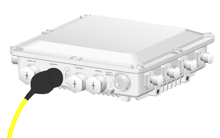
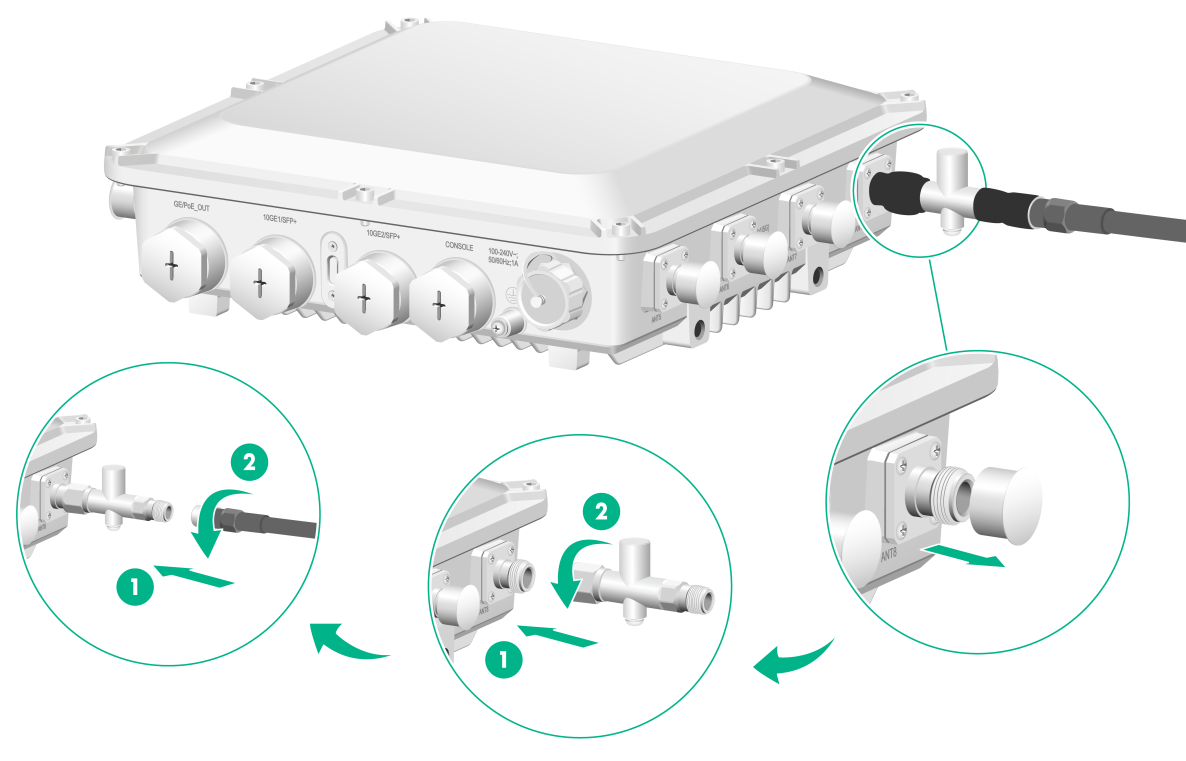
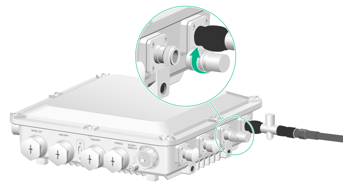
1. Remove the weatherproof plug from the antenna connector on the AP.
2. Connect a lightning arrester to the antenna connector.
3. Connect the RF cable to the lightning arrester.
4. Wrap each connection with weatherproof tape. Smooth the tape edges to ensure full adhesion.
Figure2-30 Connecting an RF cable
5. Attach loads to unused antenna connectors to avoid radio interference.
Figure2-31 Attaching loads to unused antenna connectors
Connecting the power cord
|
|
WARNING! · If you install the AP at a humid location, make sure the power source can provide good grounding fault protection. · When connecting the power cord, first connect the power cord to the AP, and then connect the power cord to the power source. · Use a weatherproof power cord. · Make sure AP installation is complete and the AP is installed correctly before powering on the AP. |
|
|
CAUTION: To prevent device damage, attach weatherproof caps tightly to connectors that are not in use. |
|
|
NOTE: When you apply weatherproof tape to the power cord, follow these restrictions and guidelines: · Make sure you attach the adhesive side of the tape to the cable connector. · Pull the tape as needed for overlap. · Start wrapping at the top of the connector, and overlap the tape to half-width. Avoid creases or wrinkles and press the tape against the connection so that there are no gaps. Smooth each wrapped layer with your hands to ensure full adhesion. |
AC liquid-tight adapter
Figure2-32 shows a AC liquid-tight adapter. Table2-1 describes the adapter specifications.
Figure2-32 AP power connector and AC liquid-tight adapter header

Table2-1 Weatherproof AC connector specifications
|
Item |
Specification |
|
Cable diameter |
5.5 to 8 mm (0.22 to 0.32 in) |
|
Maximum current |
20 A |
|
Maximum voltage |
250 V |
|
Power cord wires |
16 AWG to 20 AWG |
Connecting the AC power cord
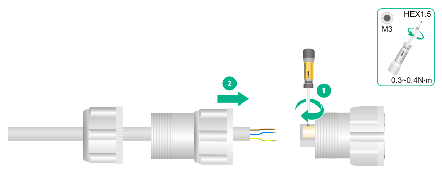
1. Attach the fastening nut to the AC liquid-tight adapter header.
Figure2-33 Assembling the nut and the liquid-tight adapter
2. Use a hex screwdriver to loosen the screws on the header, and then feed the cable through the sealing nut and sealing washer
Figure2-34 Feeding a cable through the sealing nut
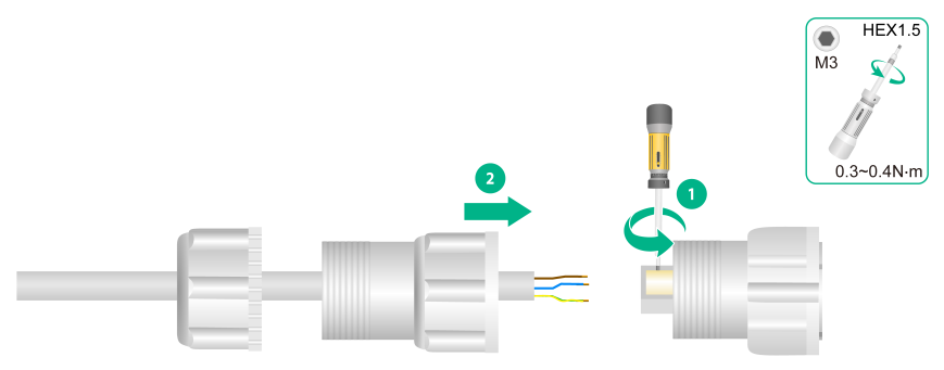
3. Use a hex screwdriver to fasten the screws for the wires to be secured to the adapter header, and then fasten the sealing washer to the header.
Figure2-35 Securing the power cord wires to the adapter header
4. Use a wrench or wear nonslip gloves to fasten the sealing nut to the sealing washer.
Figure2-36 Fastening the sealing nut

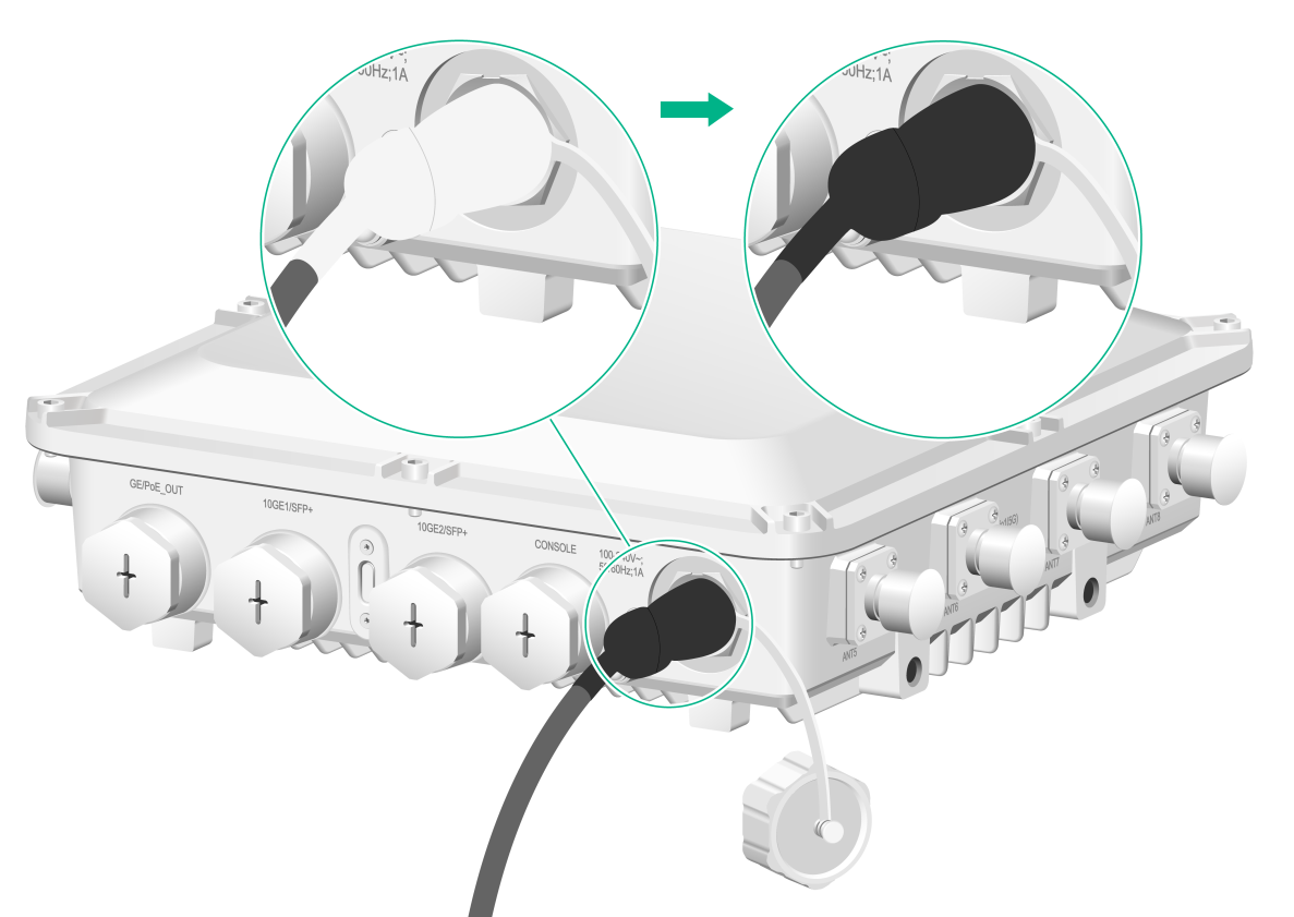
5. Connect the power cord to the AP. Apply weatherproof tape over the connection and smooth the tape edges to ensure full adhesion.
Figure2-37 Wrapping the connection
Connecting the grounding cable
|
|
CAUTION: · Correctly connecting the grounding cable is crucial to lightning protection and EMI protection. · Before connecting the AP to the power source, make sure the grounding cable is correctly connected. |
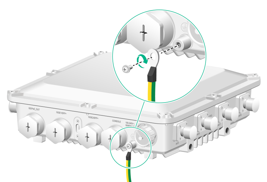
Feed the ring terminal-end of the grounding cable through the base and then use the grounding screw to attach the ring terminal to grounding point on the AP.
Figure2-38 Connecting the grounding cable to the AP
Labeling cables
After cable connection, attach labels to each cable as a best practice for future maintenance.
· Attach a label to both ends of a cable and every certain distance.
· Use cable flags or cable sleeves to label antenna and Ethernet cables. Use cable flags to label fiber cables.
· Use waterproof labels with clear content. Attach labels to proper places where they can be seen directly.
Verifying the installation
After the installation is complete, check the following items before powering on the AP:
· The power source meets the power specification of the AP.
· The AP is reliably grounded.
· The Ethernet cables are correctly connected.
· The cables are correctly labeled.
· The unused ports on the AP are sealed with waterproof plugs.
Powering on the AP
|
|
IMPORTANT: Make sure all cables are correctly connected and the AP is connected to the power source correctly before powering on the AP. |
Switch on the external power source and verify that the AP is operating correctly by examining the LED on the AP. For more information about the LED, see "Appendix B LEDs and Ports."
Connecting the AP to the network
All AP settings are configured on the AC. To verify network connectivity of the AP, execute the display wlan ap all command on the AC. If the AP status is R/M, the AP has been connected to the network.
<AC> display wlan ap all
Total number of APs: 1
Total number of connected APs: 1
Total number of connected manual APs: 1
Total number of connected auto APs: 0
Total number of connected common APs: 1
Total number of connected WTUs: 0
Total number of inside APs: 0
Maximum supported APs: 3072
Remaining APs: 3071
Total AP licenses: 128
Remaining AP licenses: 127
AP information
State : I = Idle, J = Join, JA = JoinAck, IL = ImageLoad
C = Config, DC = DataCheck, R = Run M = Master, B = Backup
AP name APID State Model Serial ID
3 Appendix A Technical specifications
Table3-1 Technical specifications
|
Item |
Specification |
|
Dimensions (H × W × D) |
280 × 280 × 85 mm (11.02 × 11.02 × 3.35 in) |
|
Weight |
3.2 kg (7.05 lb) |
|
52 W |
|
|
IEEE standards |
IEEE802.11a/b/g/n/ac/ax |
|
Material |
Cast aluminum |
4 Appendix B LEDs and Ports
LEDs
Table4-1 LED descriptions
|
LED |
Status |
Description |
||
|
|
Off |
No power is present. |
||
|
Yellow |
Steady on |
The AP is initializing. |
||
|
Flashing at 1 Hz |
No radio cards have been detected. |
|||
|
Flashing at 2 Hz |
The Ethernet interfaces are down and no mesh links are established. |
|||
|
Green |
Steady on |
The AP has registered with an AC, but does not have any associated clients. |
||
|
Flashing at 0.5 Hz |
The AP is starting up. |
|||
|
Flashing at 1 Hz |
Only the 2.4G radio has associated clients. |
|||
|
Flashing at 2 Hz |
The AP is upgrading the image. |
|||
|
Blue |
Flashing at 1 Hz |
Only the 5G radio has associated clients. |
||
|
Alternating between green and blue at 1 Hz |
Both the 2.4G and 5G radios have associated clients. |
|||
Ports
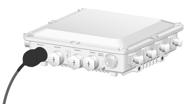
Figure4-1 Front view
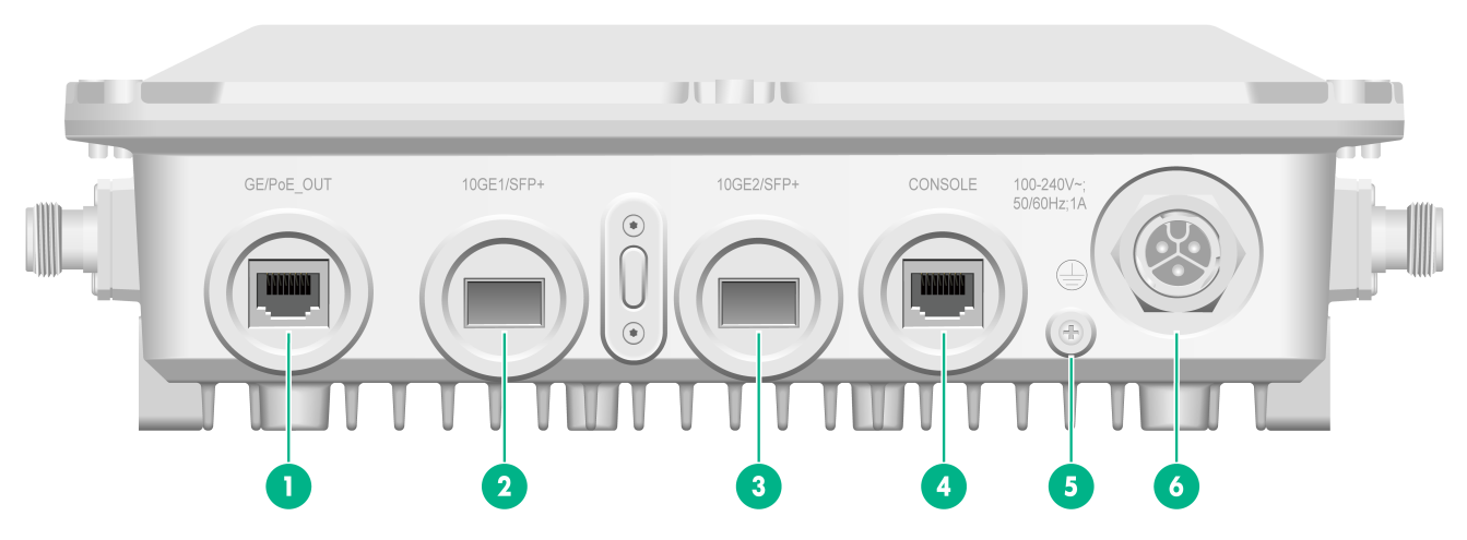
|
(1) GE/PoE_OUT port |
(2) 10GE1/SFP+ port |
(3) 10GE2/SFP+ port |
|
(4) Console port |
(5) Grounding screw |
(6) Power receptacle |
Figure4-2 Left view
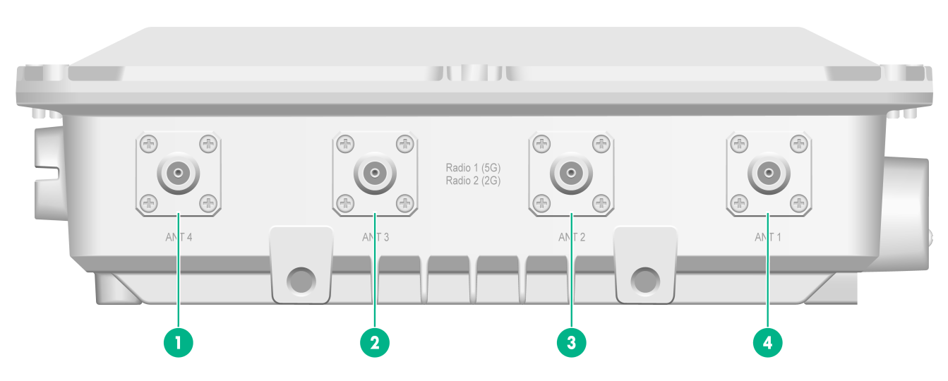
|
(1) to (4) Antenna ports ANT1/2/3/4 for radio 1 (5G) or radio 2 (2G) |
Figure4-3 Right view
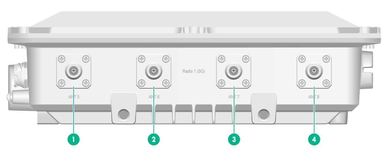
|
(1) to (4) Antenna ports ANT5/6/7/8 for radio 1 (5G) |
Figure4-4 Rear view
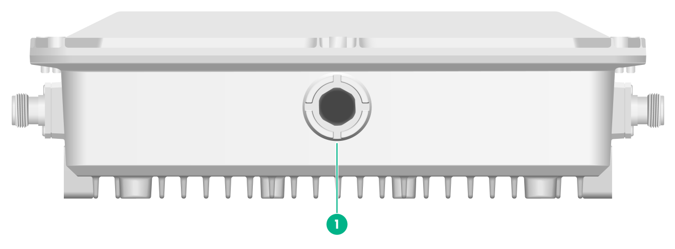
|
(1) Vent valve |
Table4-2 Port descriptions
|
Port |
Standards and protocols |
Description |
|
GE/PoE_OUT |
· IEEE802.3 · IEEE802.3u |
Connects the AP to an uplink device for Internet or MAN access. It is represented by interface GE1/0/1 in the MAP file and Gigabitethernet 1 for configuration on the AC. |
|
10GE1/SFP+ |
· IEEE802.3 · SFP MSA · SFF-8427 |
Connects the AP to an uplink device for Internet or MAN access. It is represented by interface XGE1/0/1 in the MAP file and Ten-Gigabitethernet 1 for configuration on the AC. |
|
10GE2SFP+ |
· IEEE802.3 · SFP MSA · SFF-8427 |
Connects the AP to an uplink device for Internet or MAN access. It is represented by interface XGE1/0/2 in the MAP file and Ten-Gigabitethernet 2 for configuration on the AC. |
|
CONSOLE |
RS/EIA-232 |
For device configuration and management by the maintenance engineers. |
|
Power receptacle |
N/A |
Receives 100 to 264 VAC power supply. |
|
Radio1 (5G) ANT1/2/3/4/5/6/7/8 |
· IEEE802.11a · IEEE802.11n · IEEE802.11ac · IEEE802.11ac wave2 · IEEE802.11ax |
Connects RF cables. |
|
Radio2 (2G) ANT1/2/3/4 |
· IEEE802.11a · IEEE802.11b · IEEE802.11g · IEEE802.11n · IEEE802.11ax |
Connects RF cables. |
5 Appendix C Transceiver modules
Transceiver module view
An SFP transceiver module is required if you are to use the SFP fiber port. The AP supports only fibers with LC connectors.
Figure5-1 SFP transceiver module
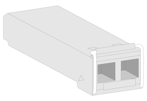
Figure5-2 Fibers with LC connectors
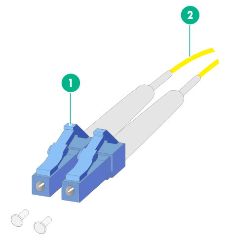
|
(1) LC fiber connector |
(2) Fiber |
Transceiver module specifications
|
Item |
SFP-XG-CPRI-IR-SM1310 |
SFP-XG-CPRI-LR-SM1310 |
|
Central wavelength |
1310 nm |
1310 nm |
|
Max transmission distance |
1.4 km (4593.17 ft) |
10 km (6.21 miles) |
|
Data rate |
1250 Mbps |
1250 Mbps |
|
Connector type |
Duplex LC |
Duplex LC |
|
Fiber mode |
SMF |
SMF |
|
Fiber diameter |
9 μm |
9 μm |
|
Output optical power |
–8.2 to +0.5 dBm |
–8.2 to +0.5 dBm |
|
Receiver sensitivity |
≤ –14.4 dBm |
≤ –14.4 dBm |
|
Light saturation |
≤ 0.5 dBm |
≤ 0.5 dBm |
