- Table of Contents
- Related Documents
-
| Title | Size | Download |
|---|---|---|
| 01-H3C Wireless Products VLAN Deployment Guide | 206.51 KB |
|
H3C Wireless Products |
|
VLAN Deployment Guide |
New H3C Technologies Co., Ltd.
http://www.h3c.com
Document version: 6W100-20220830
Contents
Management VLAN and its configuration methods
Setting the PVID of the access device to which the AP attached
Specifying the management VLAN on the AP
Recommended configuration for management and service VLANs
Configuring VLANs for one-arm AC WLAN deployment in centralized forwarding mode
Configuring VLANs for inline-AC WLAN deployment in centralized forwarding mode
Configuring VLANs for one-arm AC WLAN deployment in local forwarding mode
Configuring VLANs for inline AC WLAN deployment in local forwarding mode
Introduction
By default, H3C devices transmit both management and service packets in VLAN 1. Using this default VLAN setting can cause security and other network issues.
This document helps you optimize VLAN deployment for improved security and performance by providing VLAN deployment recommendations for WLAN networks in centralized forwarding and local forwarding modes.
Management VLAN and its configuration methods
The management VLAN transmits CAPWAP tunneled AP management packets and service data packets.
The following are the methods to specify the management VLAN for an AP:
· Setting the PVID of the access device to which the AP attached
· Specifying the management VLAN on the AP
Setting the PVID of the access device to which the AP attached
By default, AP management packets are VLAN untagged. When they arrive at the AP-attached access switch, the access switch tags the AP management packets with the PVID of the port to which the AP attached.
For example, an AP is attached to interface GigbitEthernet 1/0/1 on the access switch. To use VLAN 100 as its AP management VLAN, set the PVID of GigbitEthernet 1/0/1 to 100, as follows:
<Switch> system-view
[Switch] interface gigabitEthernet 1/0/1
[Switch-GigabitEthernet1/0/1] port trunk pvid vlan 100
|
|
NOTE: By default, the PVID on a port is 1 if you do not change the PVID on that port. In this situation, VLAN 1 will be the management VLAN for the AP. |
Specifying the management VLAN on the AP
|
|
IMPORTANT: As a best practice, set the management VLAN for an AP by setting the PVID of the AP-attached access port as long as possible. Specify the management VLAN on the AP only in special scenarios, for example, when you do not need to use the default VLAN (VLAN 1) on the AP. |
To have the AP use a VLAN other than VLAN 1 as the management, execute the management-vlan command on the AP, for example:
<ap1> system-view
[ap1] wlan management-vlan 100
|
|
IMPORTANT: If this method is used, make sure the AP-attached switch port allows the specified management VLAN to pass through. |
Service VLAN
A service VLAN transmits service data packets. The default service VLAN is VLAN 1.
By default, Layer 2 Ethernet ports on H3C switches are added to VLAN 1 so they can come online to forward traffic immediately after they connect to the network. This results in a large broadcast domain.
As a best practice to improve security and performance, do not use VLAN 1 as the management VLAN or a service VLAN.
Recommended configuration for management and service VLANs
The following information uses examples to describe the procedure of configuring management and service VLANs for WLAN networks in centralized and local forwarding modes.
|
|
IMPORTANT: As a best practice, use separate VLANs as the management VLAN and service VLANs. Avoid using VLAN 1 as the management VLAN or a service VLAN as long as possible. |
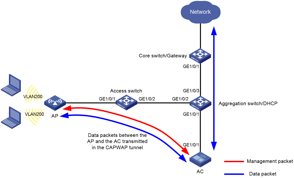
Configuring VLANs for one-arm AC WLAN deployment in centralized forwarding mode
Network configuration
Figure 1 shows a one-arm AC WLAN deployment in centralized forwarding mode.
In this scenario, you must perform the following tasks:
· Create the management VLAN and service VLANs on the AC.
· Configure the network devices between the AC and APs to allow packets from the management VLAN to pass through.
· Configure the network devices between the AC and upper-layer network to allow packets from the service VLANs to pass through.
This example uses VLAN 100 as the management VLAN and uses VLAN 200 as a service VLAN.
Procedure
1. Configure the access switch:
# Create VLAN 100 for AP management.
<Access Switch> system-view
[Access Switch] vlan 100
[Access Switch-vlan100] quit
# Configure GigabitEthernet 1/0/1 (port towards the AP) as a trunk port, and remove it from VLAN 1.
[Access Switch] interface gigabitethernet 1/0/1
[Access Switch-GigabitEthernet1/0/1] port link-type trunk
[Access Switch-GigabitEthernet1/0/1] undo port trunk permit vlan 1
# Set the PVID of GigabitEthernet 1/0/1 to VLAN 100, and assign it to VLAN 100.
[Access Switch-GigabitEthernet1/0/1] port trunk pvid vlan 100
[Access Switch-GigabitEthernet1/0/1] port trunk permit vlan 100
[Access Switch-GigabitEthernet1/0/1] quit
# Configure GigabitEthernet 1/0/2 (port towards the aggregation switch) as a trunk port, remove it from VLAN 1, and assign it to VLAN 100.
[Access Switch] interface gigabitEthernet 1/0/2
[Access Switch-GigabitEthernet1/0/2] port link-type trunk
[Access Switch-GigabitEthernet1/0/2] undo port trunk permit vlan 1
[Access Switch-GigabitEthernet1/0/2] port trunk permit vlan 100
[Access Switch-GigabitEthernet1/0/2] quit
2. Configure the aggregation switch:
# Create VLAN 100 (the VLAN for AP management).
<Aggregation Switch> system-view
[Aggregation Switch] vlan 100
[Aggregation Switch-vlan100] quit
# Create VLAN 200 (the service VLAN for WLAN clients).
[Aggregation Switch] vlan 200
[Aggregation Switch-vlan200] quit
# Configure GigabitEthernet 1/0/2 (port towards the access switch) as a trunk port, remove it from VLAN 1, and assign it to VLAN 100.
[Aggregation Switch] interface gigabitEthernet 1/0/2
[Aggregation Switch-GigabitEthernet1/0/2] port link-type trunk
[Aggregation Switch-GigabitEthernet1/0/2] undo port trunk permit vlan 1
[Aggregation Switch-GigabitEthernet1/0/2] port trunk permit vlan 100
[Aggregation Switch-GigabitEthernet1/0/2] quit
# Configure GigabitEthernet 1/0/1 (port towards the AC) as a trunk port, remove it from VLAN 1, and assign it to VLAN 100 and VLAN 200.
[Aggregation Switch] interface gigabitEthernet 1/0/1
[Aggregation Switch-GigabitEthernet1/0/1] port link-type trunk
[Aggregation Switch-GigabitEthernet1/0/1] undo port trunk permit vlan 1
[Aggregation Switch-GigabitEthernet1/0/1] port trunk permit vlan 100 200
[Aggregation Switch-GigabitEthernet1/0/1] quit
# Configure GigabitEthernet 1/0/3 (port towards the core switch) as a trunk port, remove it from VLAN 1, and assign it to VLAN 200.
[Aggregation Switch] interface gigabitEthernet 1/0/3
[Aggregation Switch-GigabitEthernet1/0/3] port link-type trunk
[Aggregation Switch-GigabitEthernet1/0/3] undo port trunk permit vlan 1
[Aggregation Switch-GigabitEthernet1/0/3] port trunk permit vlan 200
[Aggregation Switch-GigabitEthernet1/0/3] quit
3. Configure the AC:
# Create VLAN 100 (the VLAN for AP management).
<AC> system-view
[AC] vlan 100
[AC-vlan100] quit
# Create VLAN 200 (the service VLAN for WLAN clients).
[AC] vlan 200
[AC-vlan200] quit
# Configure GigabitEthernet 1/0/1 (port towards the aggregation switch) as a trunk port, remove it from VLAN 1, and assign it to VLAN 100 and VLAN 200.
[AC] interface gigabitethernet 1/0/1
[AC-GigabitEthernet1/0/1] port link-type trunk
[AC-GigabitEthernet1/0/1] undo port trunk permit vlan 1
[AC-GigabitEthernet1/0/1] port trunk permit vlan 100 200
[AC-GigabitEthernet1/0/1] quit
4. Configure the core switch:
# Create VLAN 200 (the service VLAN for WLAN clients).
<Core Switch> system-view
[Core Switch] vlan 200
[Core Switch-vlan200] quit
# Configure GigabitEthernet 1/0/1 (port towards the aggregation switch) as a trunk port, remove it from VLAN 1, and assign it to VLAN 200.
[Core Switch] interface gigabitEthernet 1/0/1
[Core Switch-GigabitEthernet1/0/1] port link-type trunk
[Core Switch-GigabitEthernet1/0/1] undo port trunk permit vlan 1
[Core Switch-GigabitEthernet1/0/1] port trunk permit vlan 200
[Core Switch-GigabitEthernet1/0/1] quit
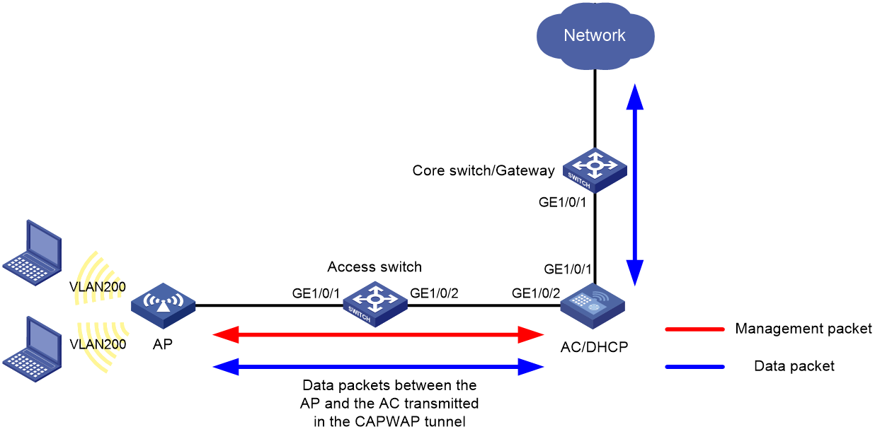
Configuring VLANs for inline-AC WLAN deployment in centralized forwarding mode
Network configuration
Figure 2 shows an inline-AC WLAN deployment in centralized forwarding mode.
In this scenario, you must perform the following tasks:
· Create the management VLAN and service VLANs on the AC.
· Configure the network devices between the AC and APs to allow packets from the management VLAN to pass through.
· Configure the network devices between the AC and upper-layer network to allow packets from the service VLANs to pass through.
This example uses VLAN 100 as the management VLAN and uses VLAN 200 as a service VLAN.
Procedure
1. Configure the access switch:
# Create VLAN 100 for AP management.
<Access Switch> system-view
[Access Switch] vlan 100
[Access Switch-vlan100] quit
# Configure GigabitEthernet 1/0/1 (port towards the AP) as a trunk port, and remove it from VLAN 1.
[Access Switch] interface gigabitethernet 1/0/1
[Access Switch-GigabitEthernet1/0/1] port link-type trunk
[Access Switch-GigabitEthernet1/0/1] undo port trunk permit vlan 1
# Set the PVID of GigabitEthernet 1/0/1 to VLAN 100, and assign it to VLAN 100.
[Access Switch-GigabitEthernet1/0/1] port trunk pvid vlan 100
[Access Switch-GigabitEthernet1/0/1] port trunk permit vlan 100
[Access Switch-GigabitEthernet1/0/1] quit
# Configure GigabitEthernet 1/0/2 (port towards the AC) as a trunk port, remove it from VLAN 1, and assign it to VLAN 100.
[Access Switch] interface gigabitEthernet 1/0/2
[Access Switch-GigabitEthernet1/0/2] port link-type trunk
[Access Switch-GigabitEthernet1/0/2] undo port trunk permit vlan 1
[Access Switch-GigabitEthernet1/0/2] port trunk permit vlan 100
[Access Switch-GigabitEthernet1/0/2] quit
2. Configure the AC:
# Create VLAN 100 (the VLAN for AP management).
<AC> system-view
[AC] vlan 100
[AC-vlan100] quit
# Create VLAN 200 (the service VLAN for WLAN clients).
[AC] vlan 200
[AC-vlan200] quit
# Configure GigabitEthernet 1/0/2 (port towards the access switch) as a trunk port, remove it from VLAN 1, and assign it to VLAN 100.
[AC] interface gigabitethernet 1/0/2
[AC-GigabitEthernet1/0/2] port link-type trunk
[AC-GigabitEthernet1/0/2] undo port trunk permit vlan 1
[AC-GigabitEthernet1/0/2] port trunk permit vlan 100
[AC-GigabitEthernet1/0/2] quit
# Configure GigabitEthernet 1/0/1 (port towards the core switch) as a trunk port, remove it from VLAN 1, and assign it to VLAN 200.
[AC] interface gigabitethernet 1/0/1
[AC-GigabitEthernet1/0/1] port link-type trunk
[AC-GigabitEthernet1/0/1] undo port trunk permit vlan 1
[AC-GigabitEthernet1/0/1] port trunk permit vlan 200
[AC-GigabitEthernet1/0/1] quit
3. Configure the core switch:
# Create VLAN 200 (the service VLAN for WLAN clients).
<Core Switch> system-view
[Core Switch] vlan 200
[Core Switch-vlan200] quit
# Configure GigabitEthernet 1/0/1 (port towards the AC) as a trunk port, remove it from VLAN 1, and assign it to VLAN 200.
[Core Switch] interface gigabitEthernet 1/0/1
[Core Switch-GigabitEthernet1/0/1] port link-type trunk
[Core Switch-GigabitEthernet1/0/1] undo port trunk permit vlan 1
[Core Switch-GigabitEthernet1/0/1] port trunk permit vlan 200
[Core Switch-GigabitEthernet1/0/1] quit
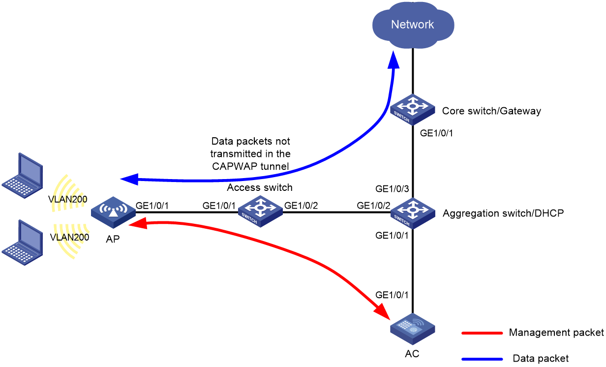
Configuring VLANs for one-arm AC WLAN deployment in local forwarding mode
Network configuration
Figure 3 shows a one-arm AC WLAN deployment in local forwarding mode.
In this scenario, perform the following tasks:
· Configure the AP management VLAN on the AC.
· Configure service VLANs on the AC if the AC must process service packets from WLAN clients, typically in either of the following situations:
¡ The gateway for the WLAN clients is placed on the AC.
¡ 802.1X authentication is used. In this situation, authentication packets are CAPWAP tunneled. The AC must have the service VLANs.
If no service traffic traverses the AC, you do not need to configure service VLANs on the AC.
· Configure the network devices between the AC and APs to allow packets from the management VLAN to pass through.
· Configure the network devices between the APs and upper-layer network to allow packets from the service VLANs to pass through.
This example uses VLAN 100 as the management VLAN and uses VLAN 200 as a service VLAN.
Procedure
1. Configure the service VLAN settings for APs in an .txt AP configuration file:
# Configure the service VLAN settings for APs in a .txt AP configuration file:
System-view
vlan 200
interface gigabitethernet1/0/1
port link-type trunk
port trunk permit vlan 200
# Store the file in the root directory of the storage medium on the AC. (Details not shown.)
2. Configure the access switch:
# Create VLAN 100 (the VLAN for AP management).
<Access Switch> system-view
[Access Switch] vlan 100
[Access Switch-vlan100] quit
# Create VLAN 200 (the service VLAN for WLAN clients).
[Access Switch] vlan 200
[Access Switch-vlan200] quit
# Configure GigabitEthernet 1/0/1 (port towards the AP) as a trunk port, and remove it from VLAN 1.
[Access Switch] interface gigabitethernet 1/0/1
[Access Switch-GigabitEthernet1/0/1] port link-type trunk
[Access Switch-GigabitEthernet1/0/1] undo port trunk permit vlan 1
# Set the PVID of GigabitEthernet 1/0/1 to VLAN 100, and assign it to VLAN 100 and VLAN 200.
[Access Switch-GigabitEthernet1/0/1] port trunk pvid vlan 100
[Access Switch-GigabitEthernet1/0/1] port trunk permit vlan 100 200
[Access Switch-GigabitEthernet1/0/1] quit
# Configure GigabitEthernet 1/0/2 (port towards the aggregation switch) as a trunk port, remove it from VLAN 1, and assign it to VLAN 100 and VLAN 200.
[Access Switch] interface gigabitEthernet 1/0/2
[Access Switch-GigabitEthernet1/0/2] port link-type trunk
[Access Switch-GigabitEthernet1/0/2] undo port trunk permit vlan 1
[Access Switch-GigabitEthernet1/0/2] port trunk permit vlan 100 200
[Access Switch-GigabitEthernet1/0/2] quit
3. Configure the aggregation switch:
# Create VLAN 100 (the VLAN for AP management).
<Aggregation Switch> system-view
[Aggregation Switch] vlan 100
[Aggregation Switch-vlan100] quit
# Create VLAN 200 (the service VLAN for WLAN clients).
[Aggregation Switch] vlan 200
[Aggregation Switch-vlan200] quit
# Configure GigabitEthernet 1/0/2 (port towards the access switch) as a trunk port, remove it from VLAN 1, and assign it to VLAN 100 and VLAN 200.
[Aggregation Switch] interface gigabitEthernet 1/0/2
[Aggregation Switch-GigabitEthernet1/0/2] port link-type trunk
[Aggregation Switch-GigabitEthernet1/0/2] undo port trunk permit vlan 1
[Aggregation Switch-GigabitEthernet1/0/2] port trunk permit vlan 100 200
[Aggregation Switch-GigabitEthernet1/0/2] quit
# Configure GigabitEthernet 1/0/1 (port towards the AC) as a trunk port, remove it from VLAN 1, and assign it to VLAN 100.
[Aggregation Switch] interface gigabitEthernet 1/0/1
[Aggregation Switch-GigabitEthernet1/0/1] port link-type trunk
[Aggregation Switch-GigabitEthernet1/0/1] undo port trunk permit vlan 1
[Aggregation Switch-GigabitEthernet1/0/1] port trunk permit vlan 100
[Aggregation Switch-GigabitEthernet1/0/1] quit
# Configure GigabitEthernet 1/0/3 (port towards the core switch) as a trunk port, remove it from VLAN 1, and assign it to VLAN 200.
[Aggregation Switch] interface gigabitEthernet 1/0/3
[Aggregation Switch-GigabitEthernet1/0/3] port link-type trunk
[Aggregation Switch-GigabitEthernet1/0/3] undo port trunk permit vlan 1
[Aggregation Switch-GigabitEthernet1/0/3] port trunk permit vlan 200
[Aggregation Switch-GigabitEthernet1/0/3] quit
4. Configure the AC:
# Create VLAN 100 (the VLAN for AP management).
<AC> system-view
[AC] vlan 100
[AC-vlan100] quit
# Configure GigabitEthernet 1/0/1 (port towards the aggregation switch) as a trunk port, remove it from VLAN 1, and assign it to VLAN 100.
[AC] interface gigabitethernet 1/0/1
[AC-GigabitEthernet1/0/1] port link-type trunk
[AC-GigabitEthernet1/0/1] undo port trunk permit vlan 1
[AC-GigabitEthernet1/0/1] port trunk permit vlan 100
[AC-GigabitEthernet1/0/1] quit
5. Configure the core switch:
# Create VLAN 200 (the service VLAN for WLAN clients).
<Core Switch> system-view
[Core Switch] vlan 200
[Core Switch-vlan200] quit
# Configure GigabitEthernet 1/0/1 (port towards the aggregation switch) as a trunk port, remove it from VLAN 1, and assign it to VLAN 200.
[Core Switch] interface gigabitEthernet 1/0/1
[Core Switch-GigabitEthernet1/0/1] port link-type trunk
[Core Switch-GigabitEthernet1/0/1] undo port trunk permit vlan 1
[Core Switch-GigabitEthernet1/0/1] port trunk permit vlan 200
[Core Switch-GigabitEthernet1/0/1] quit
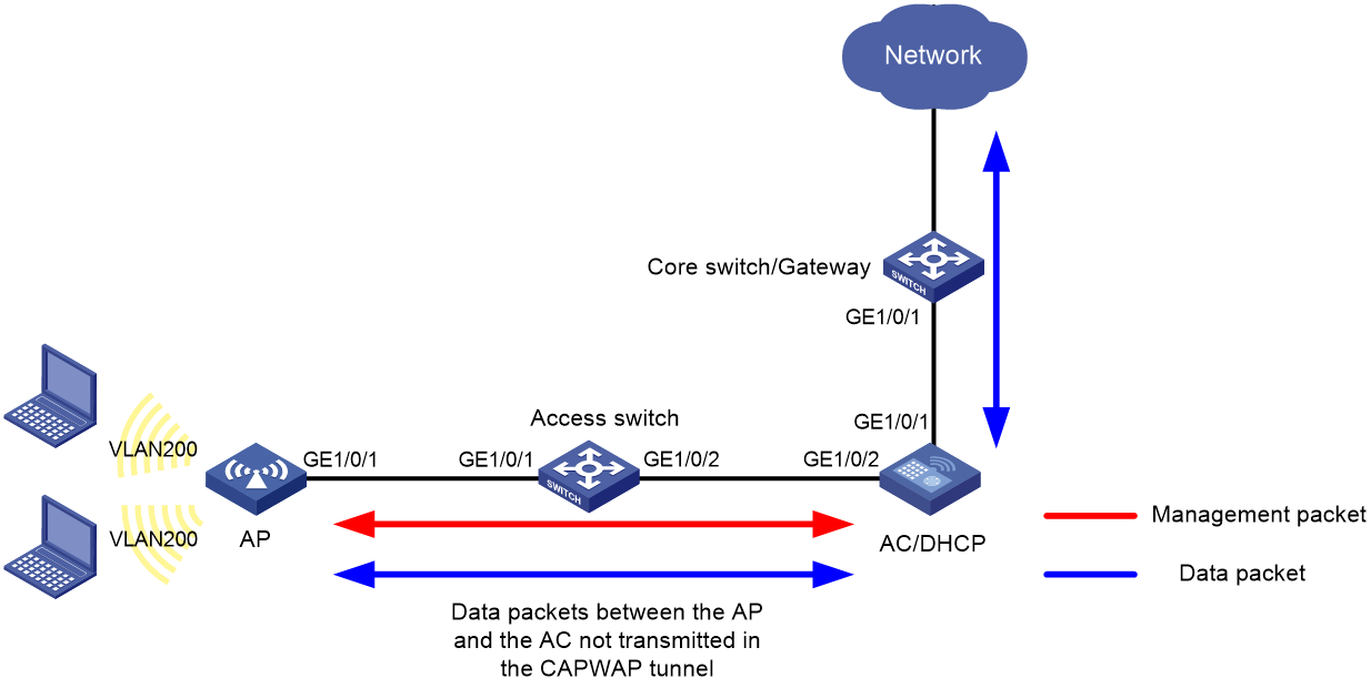
Configuring VLANs for inline AC WLAN deployment in local forwarding mode
Network configuration
Figure 4 shows an inline-AC WLAN deployment in local forwarding mode.
In this scenario, you must perform the following tasks:
· Create the management VLAN and service VLANs on the AC.
· Configure the network devices between the AC and APs to allow packets from the management VLAN to pass through.
· Configure the network devices between the AC and upper-layer network to allow packets from the service VLANs to pass through.
This example uses VLAN 100 as the management VLAN and uses VLAN 200 as a service VLAN.
Procedure
1. Configure the service VLAN settings for APs in an .txt AP configuration file:
# Configure the service VLAN settings for APs in an .txt AP configuration file:
System-view
vlan 200
interface gigabitethernet1/0/1
port link-type trunk
port trunk permit vlan 200
# Store the file in the root directory of the storage medium on the AC. (Details not shown.)
2. Configure the access switch:
# Create VLAN 100 (the VLAN for AP management).
<Access Switch> system-view
[Access Switch] vlan 100
[Access Switch-vlan100] quit
# Create VLAN 200 (the service VLAN for WLAN clients).
[Access Switch] vlan 200
[Access Switch-vlan200] quit
# Configure GigabitEthernet 1/0/1 (port towards the AP) as a trunk port, and remove it from VLAN 1.
[Access Switch] interface gigabitethernet 1/0/1
[Access Switch-GigabitEthernet1/0/1] port link-type trunk
[Access Switch-GigabitEthernet1/0/1] undo port trunk permit vlan 1
# Set the PVID of GigabitEthernet 1/0/1 to VLAN 100, and assign it to VLAN 100 and VLAN 200.
[Access Switch-GigabitEthernet1/0/1] port trunk pvid vlan 100
[Access Switch-GigabitEthernet1/0/1] port trunk permit vlan 100 200
[Access Switch-GigabitEthernet1/0/1] quit
# Configure GigabitEthernet 1/0/2 (port towards the AC) as a trunk port, remove it from VLAN 1, and assign it to VLAN 100 and VLAN 200.
[Access Switch] interface gigabitEthernet 1/0/2
[Access Switch-GigabitEthernet1/0/2] port link-type trunk
[Access Switch-GigabitEthernet1/0/2] undo port trunk permit vlan 1
[Access Switch-GigabitEthernet1/0/2] port trunk permit vlan 100 200
[Access Switch-GigabitEthernet1/0/2] quit
3. Configure the AC:
# Create VLAN 100 (the VLAN for AP management).
<AC> system-view
[AC] vlan 100
[AC-vlan100] quit
# Create VLAN 200 (the service VLAN for WLAN clients).
[AC] vlan 200
[AC-vlan200] quit
# Configure GigabitEthernet 1/0/2 (port towards the access switch) as a trunk port, remove it from VLAN 1, and assign it to VLAN 100 and VLAN 200.
[AC] interface gigabitethernet 1/0/2
[AC-GigabitEthernet1/0/2] port link-type trunk
[AC-GigabitEthernet1/0/2] undo port trunk permit vlan 1
[AC-GigabitEthernet1/0/2] port trunk permit vlan 100 200
[AC-GigabitEthernet1/0/2] quit
# Configure GigabitEthernet 1/0/1 (port towards the core switch) as a trunk port, remove it from VLAN 1, and assign it to VLAN 200.
[AC] interface gigabitethernet 1/0/1
[AC-GigabitEthernet1/0/1] port link-type trunk
[AC-GigabitEthernet1/0/1] undo port trunk permit vlan 1
[AC-GigabitEthernet1/0/1] port trunk permit vlan 200
[AC-GigabitEthernet1/0/1] quit
4. Configure the core switch:
# Create VLAN 200 (the service VLAN for WLAN clients).
<Core Switch> system-view
[Core Switch] vlan 200
[Core Switch-vlan200] quit
# Configure GigabitEthernet 1/0/1 (port towards the AC) as a trunk port, remove it from VLAN 1, and assign it to VLAN 200.
[Core Switch] interface gigabitEthernet 1/0/1
[Core Switch-GigabitEthernet1/0/1] port link-type trunk
[Core Switch-GigabitEthernet1/0/1] undo port trunk permit vlan 1
[Core Switch-GigabitEthernet1/0/1] port trunk permit vlan 200
[Core Switch-GigabitEthernet1/0/1] quit
Troubleshooting the VLAN deployment
Clients in a service VLAN cannot come online even if the VLAN is permitted on all ports along their traffic path
Symptom
The clients in a service VLAN cannot come online even if all ports on its traffic path permit the service VLAN to pass through.
Analysis
This issue typically occurs because the VLAN has not been created on the intermediate network devices.
Solution
1. Verify that the service VLAN has been created on all the intermediate network devices.
2. Create the service VLAN if it has not been created.
3. If the issue persists, check other network settings for misconfiguration.
