- Table of Contents
- Related Documents
-
| Title | Size | Download |
|---|---|---|
| 02-Cisco ISE Server Configuration Examples | 1.01 MB |
|
|
|
H3C Access Controllers |
|
Access Authentication by Cisco ISE Server |
|
Configuration Examples |
|
|
Copyright © 2022 New H3C Technologies Co., Ltd. All rights reserved.
No part of this manual may be reproduced or transmitted in any form or by any means without prior written consent of New H3C Technologies Co., Ltd.
Except for the trademarks of New H3C Technologies Co., Ltd., any trademarks that may be mentioned in this document are the property of their respective owners.
The information in this document is subject to change without notice.
Example: Configuring Cisco ISE-based 802.1X PEAP authentication
Example: Configuring Cisco ISE-based HWTACACS authentication for SSH login
Introduction
The following information provides examples for configuring H3C access controllers to use a Cisco ISE server to authenticate wireless clients. The examples include configuring Cisco ISE-based 802.1X authentication, MAC authentication, and SSH login HWTACACS authentication.
Software versions used
The following configuration examples were created and verified on the following hardware and software versions:
· Cisco ISE server running 2.3.0.298.
· H3C access controller running R5428 or later.
Example: Configuring Cisco ISE-based 802.1X PEAP authentication
Network configuration
As shown in Figure 1, the AP is connected to the AC over the switch and the client accesses the wireless network through the AP.
Configure the devices and server to meet the following requirements:
· The client must pass 802.1X PEAP authentication to access the wireless network.
· The client and AP use the PSK AKM mode to secure data packets between them.
· The ISE server assigns an authorization ACL and an authorization VLAN to the client after the client passes 802.1X PEAP authentication.

Procedures
|
|
IMPORTANT: This configuration example only covers the major settings related to authenticating the client by 802.1X authentication on the Cisco ISE server. For information about the network connectivity settings, see the manuals for the devices and server. Make sure the devices and server have network connectivity. |
Configuring the AC
1. Configure the AC to use EAP relay to authenticate the 802.1X client.
<AC> system-view
[AC] dot1x authentication-method eap
2. Configure a RADIUS scheme:
# Create RADIUS scheme ise.
[AC] radius scheme ise
# Specify the ISE server at 8.1.1.18 as the primary authentication server and specify a shared key for secure communication with the server. Make sure the shared key is the same as the shared secret configured on the ISE server.
[AC-radius-ise] primary authentication 8.1.1.18 key cipher $c$3$FpBySjKd6TF17QmPAQ83vNM+mNuZHUw=
# Exclude the domain name from usernames sent to the ISE server.
[AC-radius-ise] user-name-format without-domain
# Specify 191.120.1.56 as the NAS IP address of RADIUS packets sent to the ISE server. Make sure the NAS IP address is the same as that specified on the ISE server for the AC.
[AC-radius-ise] nas-ip 191.120.1.56
[AC-radius-ise] quit
3. Configure an ISP domain:
# Create ISP domain ise.
[AC] domain ise
# Configure the ISP domain to use RADIUS scheme ise as the default methods for user authentication and authorization.
[AC-isp-ise] authentication default radius-scheme ise
[AC-isp-ise] authorization default radius-scheme ise
[AC-isp-ise] quit
4. Configure a service template:
# Create service template ise.
[AC] wlan service-template ise
# Set the SSID of the service template to 000AAA-MACAU.
[AC-wlan-st-ise] ssid 000AAA-MACAU
# Assign clients coming online through the service template to VLAN 71.
[AC-wlan-st-ise] vlan 71
# Enable SSID-based user isolation.
[AC-wlan-st-ise] user-isolation enable
# Set the PSK AKM mode and specify a PSK.
[AC-wlan-st-ise] akm mode psk
[AC-wlan-st-ise] preshared-key pass-phrase cipher $c$3$OXHQK8paB+3+LJWrRx1XHPLt2A3i6W79mL6Q/Q==
# Specify the AES-CCMP cipher suite, and enable the RSN IE in beacon and probe responses.
[AC-wlan-st-ise] cipher-suite ccmp
[AC-wlan-st-ise] security-ie rsn
# Set the authentication mode to 802.1X authentication and specify authentication domain ise.
[AC-wlan-st-ise] client-security authentication-mode dot1x
[AC-wlan-st-ise] dot1x domain ise
# Enable the service template.
[AC-wlan-st-ise] service-template enable
[AC-wlan-st-ise] quit
5. Configure a manual AP:
# Configure an AP named ax and specify its model and serial ID.
[AC] wlan ap ax model WA6528
[AC-wlan-ap-ax] serial-id 219801A1LH8188E00011
# Specify VLAN 1 for the AP.
[AC-wlan-ap-ax] vlan 1
# Enable radio 1 and bind service template ise to the radio.
[AC-wlan-ap-ax] radio 1
[AC-wlan-ap-ax-radio-1] radio enable
[AC-wlan-ap-ax-radio-1] service-template ise
[AC-wlan-ap-ax-radio-1] quit
[AC-wlan-ap-ax] quit
Configuring the ISE server
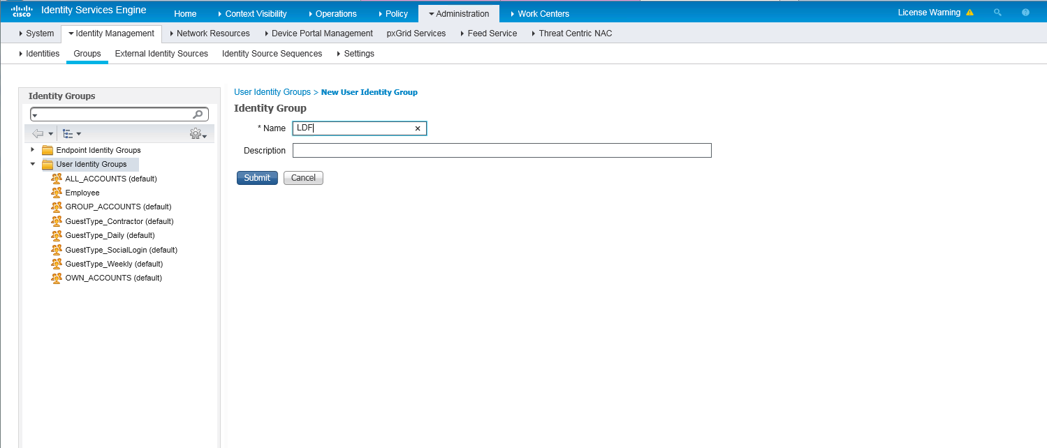
1. Create a user group:
a. On the top navigation bar, select Administration > Identity Management > Groups.
b. From the left navigation pane, select User Identity Groups.
c. Click Add.
d. On the page that opens, set the name to LDF.
e. Click Submit.
Figure 2 Creating a user group
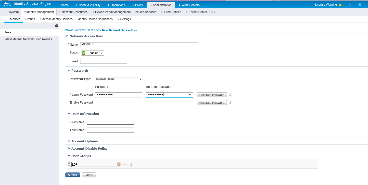
2. Create a network access user:
a. On the top navigation bar, select Administration > Identity Management > Identities.
b. From the left navigation pane, select Users.
c. Click Add.
d. On the page that opens, set the name to ldf00001 and password to Ldf123456, and bind the user to user group LDF.
Make sure the password contains uppercase letters, lowercase letters, and digits.
e. Click Submit.
Figure 3 Creating a network access user
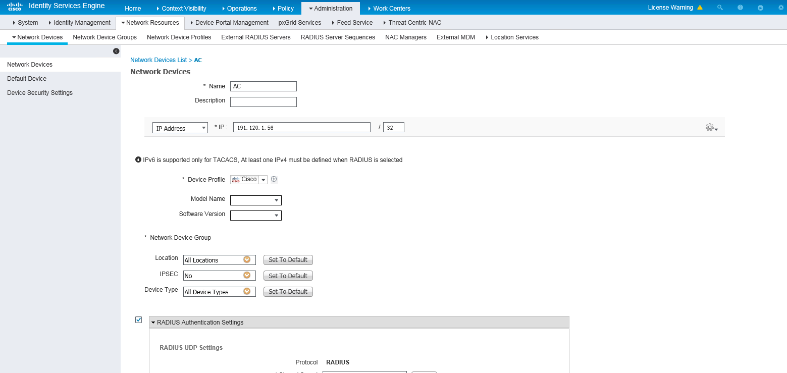
3. Add the AC to the server as a network access device:
a. On the top navigation bar, select Administration > Network Resources > Network Devices.
b. Click Add.
c. Set the name to AC, specify IP address 191.120.1.56, select RADIUS Authentication Settings, and set the shared secret to H3cc.
Make sure the IP address is the same as the NAS IP address of RADIUS packets on the AC.
Make sure the shared secret is the same as the shared key configured on the AC.
d. Save the configuration.
Figure 4 Adding the AC to the server
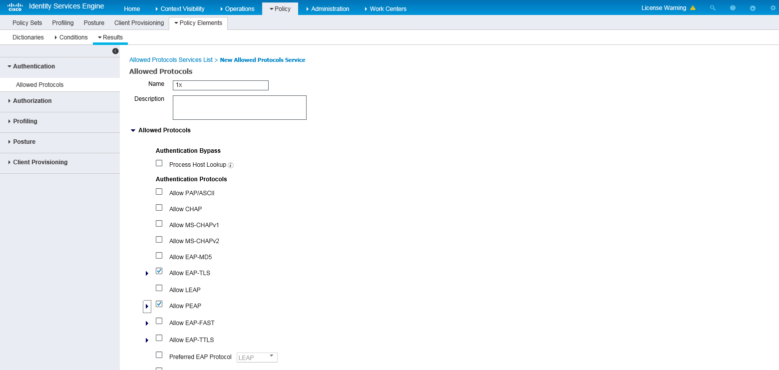
4. Configure authentication protocols:
a. On the top navigation bar, select Policy > Policy Elements > Results.
b. From the left navigation pane, select Authentication > Allowed Protocols.
c. Create an allowed protocols service named 1x, and select Allow EAP-TLS and Allow PEAP.
d. Save the configuration.
Figure 5 Creating an allowed protocols service
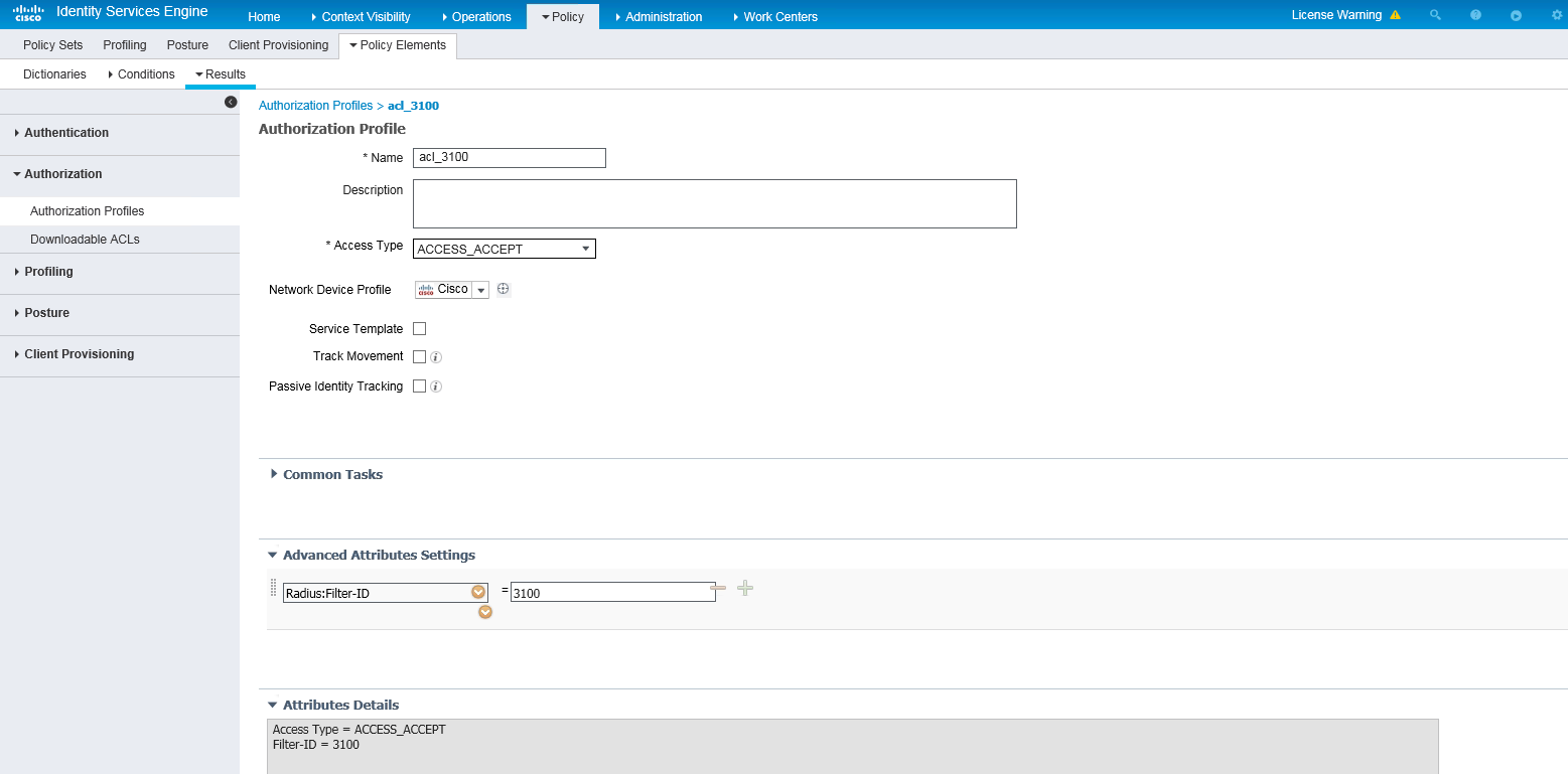
5. Configuring an authorization ACL:
a. On the top navigation bar, select Policy > Policy Elements > Results.
b. From the left navigation pane, select Authorization > Authorization Profiles.
c. Click Add.
d. In the Authorization Profile area, set the name to acl_3100 and select Cisco from the Network Device Profile field. In the Advanced Attributes Settings area, select attribute Radius:Filter-ID and set the attribute value to 3100 (an ACL number).
e. Save the configuration.
Figure 6 Configuring an authorization ACL
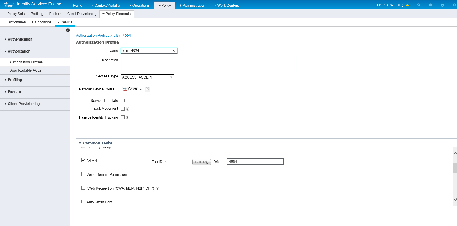
6. Configuring an authorization VLAN:
a. On the top navigation bar, select Policy > Policy Elements > Results.
b. From the left navigation pane, select Authorization > Authorization Profiles.
c. Click Add.
d. In the Authorization Profile area, set the name to vlan_4094 and select Cisco from the Network Device Profile field. In the Custom Tasks area, select the VLAN option and enter 4094 in the ID/Name field.
e. Save the configuration.
Figure 7 Configuring an authorization VLAN
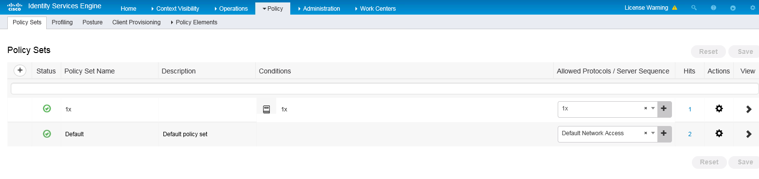
7. Configure an authentication and authorization policy set:
a. On the top navigation bar, select Policy > Policy Sets.
b. Click the plus icon + under Policy Sets.
c. Set the policy set name to 1x. Set the conditions name to 1x, select Wired_Dot1x or Wireless Dot1x as the conditions, and select 1x from the Allowed Protocols/Server Sequence list.
Figure 8 Configuring an authentication and authorization policy set
d. Click the icon in the View column for the authentication and authorization policy set.
e. In the Authorization Policy area, add an authorization policy named acl_vlan. In the Results > Profiles column for the authorization policy, select profiles acl_3100 and vlan_4094.
Figure 9 Configuring an authorization policy
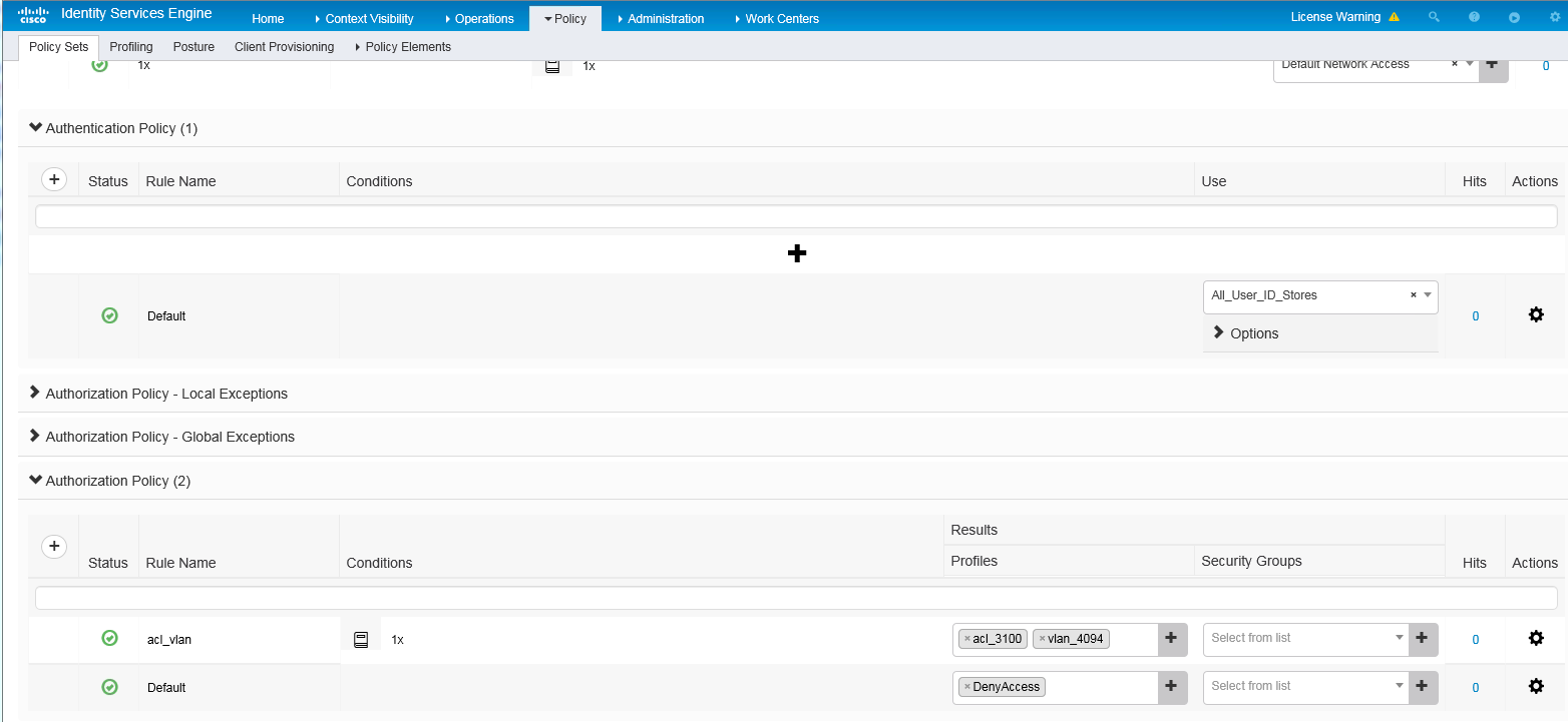
f. Save the configuration.
Verifying the configuration
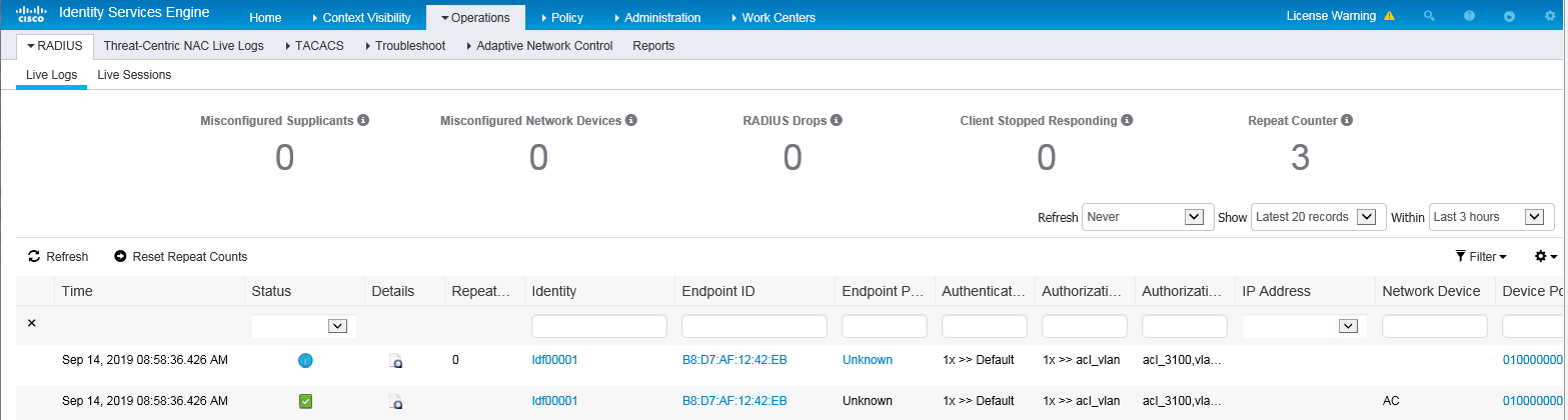
1. On the top navigation bar, select Operations > RADIUS > Live Logs. View live log information for online clients.
Figure 10 Viewing live log information for online clients
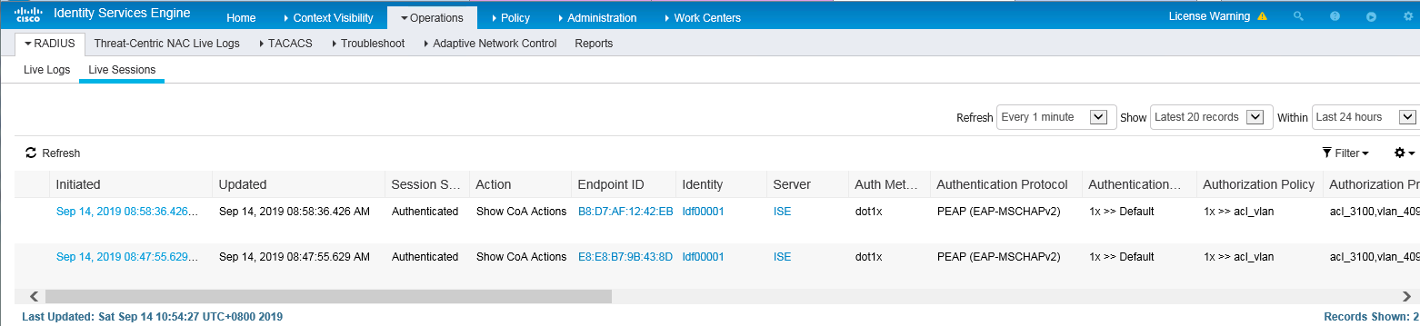
2. On the top navigation bar, select Operations > RADIUS > Live Sessions. View live session information for online clients.
Figure 11 Viewing live session information for online clients
Configuration files
#
radius scheme ise
primary authentication 8.1.1.19 key cipher $c$3$FpBySjKd6TF17QmPAQ83vNM+mNuZHUw=
user-name-format without-domain
nas-ip 191.120.1.56
#
domain ise
authentication default radius-scheme ise
authorization default radius-scheme ise
#
wlan ap ax model WA6528
serial-id 219801A1LH8188E00011
#
wlan service-template ise
ssid 000AAA-MACAU
vlan 71
user-isolation enable
akm mode dot1x
preshared-key pass-phrase cipher $c$3$OXHQK8paB+3+LJWrRx1XHPLt2A3i6W79mL6Q/Q==
cipher-suite ccmp
security-ie rsn
client-security authentication-mode dot1x
dot1x domain ise
service-template enable
#
wlan ap ax model WA6528
serial-id 219801A1LH8188E00011
vlan 1
radio 1
radio enable
service-template ise
#
dot1x authentication-method eap
Example: Configuring Cisco ISE-based HWTACACS authentication for SSH login
Network configuration
As shown in Figure 12, the PC is connected to the AC over the switch. The ISE server performs HWTACACS authentication for the client when the client logs in to the AC through SSH.
The client has the following permissions after it logs in to the AC through SSH:
· Has the permissions of the level-1 user role.
· Cannot access the display cpu-usage command.

Procedures
|
|
IMPORTANT: This configuration example only covers the major settings related to authenticating SSH login by HWTACACS authentication on the Cisco ISE server. For information about the network connectivity settings, see the manuals for the devices and server. Make sure the devices and server have network connectivity. |
Configuring the AC
1. Configure an HWTACACS scheme:
# Create HWTACACS scheme tac.
<AC> system-view
[AC] hwtacacs scheme tac
# Specify the ISE server at 8.1.1.19 as the primary authentication, authorization, and accounting servers and specify a shared key for secure communication with the ISE server. Make sure the shared key is the same as the shared secret configured on the ISE server.
[AC-hwtacacs-tac] primary authentication 8.1.1.19 key cipher $c$3$8zfqwa07HmNhvjWvEeixw5NGEGo82r/htRg=
[AC-hwtacacs-tac] primary authorization 8.1.1.19 key cipher $c$3$fARZu6PskfKoULCy46SHq0hVbNHakBUPleE=
[AC-hwtacacs-tac] primary accounting 8.1.1.19 key cipher $c$3$tBnfBlfHnO9YHBko2ZjMpzpuRqSyN3wdDPA=
# Exclude the domain name from usernames sent to the ISE server.
[AC-hwtacacs-tac] user-name-format without-domain
# Specify 191.2.1.56 as the NAS IP address of HWTACACS packets sent to the ISE server. Make sure the NAS IP address is the same as that specified on the ISE server for the AC.
[AC-hwtacacs-tac] nas-ip 191.2.1.56
[AC-hwtacacs-tac] quit
2. Configure an ISP domain:
# Create ISP domain system.
[AC] domain system
# Configure the ISP domain to use HWTACACS scheme tac for login user authentication and authorization and to not perform accounting for login users.
[AC-isp-system] authentication login hwtacacs-scheme tac
[AC-isp-system] authorization login hwtacacs-scheme tac
[AC-isp-system] accounting login none
# Configure the ISP domain to use HWTACACS scheme tac for command authorization and accounting.
[AC-isp-system] authorization command hwtacacs-scheme tac
[AC-isp-system] accounting command hwtacacs-scheme tac
[AC-isp-system] quit
3. Create local RSA and DSA key pairs and enable the SSH server.
[AC] public-key local create rsa
[AC] public-key local create dsa
[AC] ssh server enable
4. Enable the default role feature.
[AC] role default-role enable
5. Enable command authorization and accounting.
[AC] line vty 0 31
[AC-line-vty0-31] authentication-mode scheme
[AC-line-vty0-31] command authorization
[AC-line-vty0-31] command accounting
[AC-line-vty0-31] quit
Configuring the ISE server
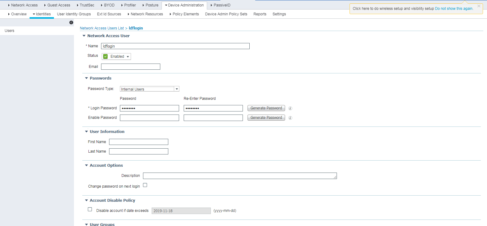
1. Create a network access user:
a. On the top navigation bar, select Work Centers > Device Administration > Identities.
b. From the left navigation pane, select Users.
c. Click Add.
d. On the page that opens, set the name to ldflogin and password to Ldf654321.
Make sure the password contains uppercase letters, lowercase letters, and digits.
e. Click Submit.
Figure 13 Creating a network access user
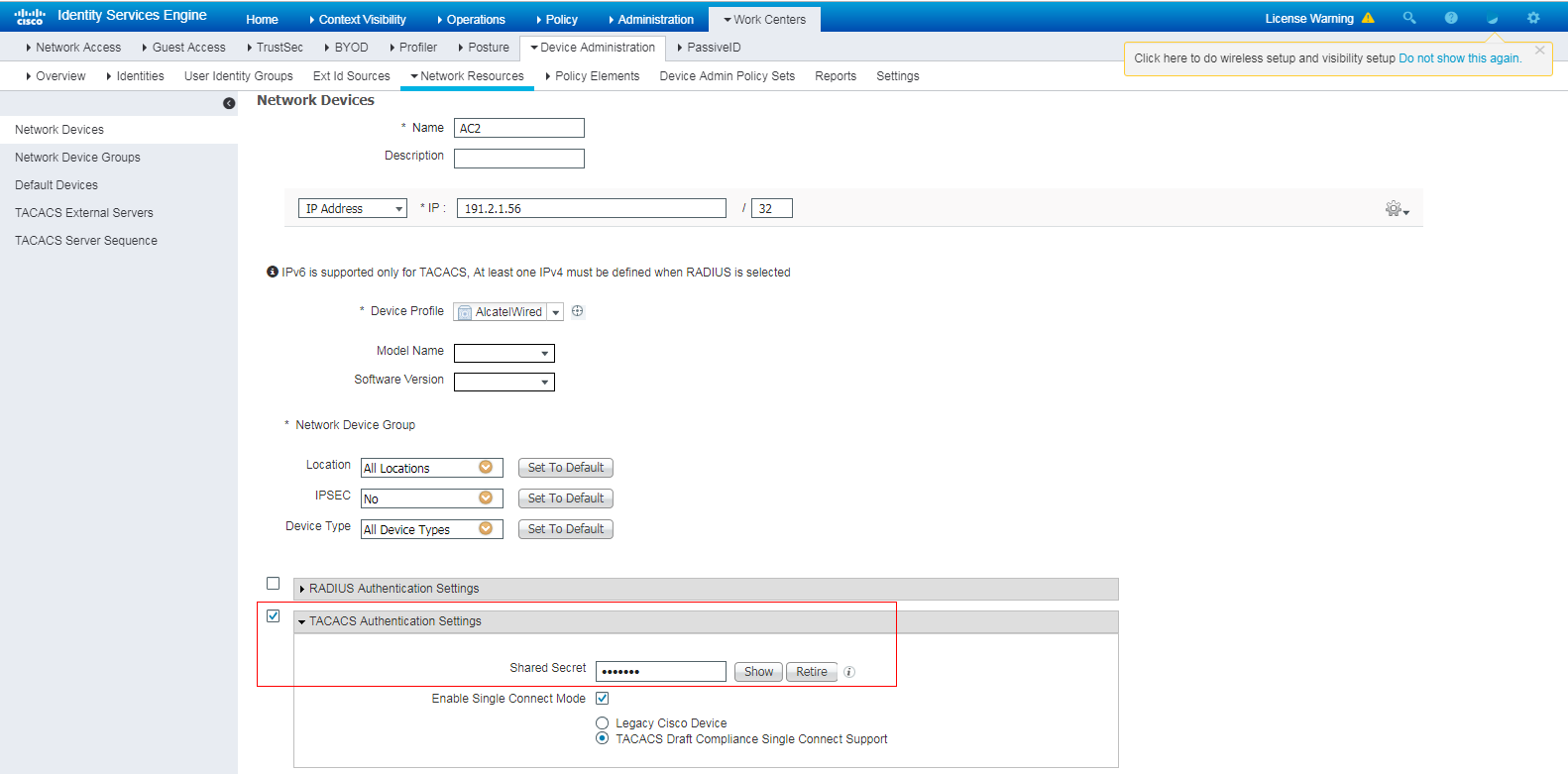
2. Add the AC to the server as a network access device:
a. On the top navigation bar, select Work Centers > Device Administration > Network Resources.
b. From the left navigation pane, select Network Devices.
c. Click Add.
d. On the page that opens, set the name to AC2, specify IP address 191.2.1.56, select TACACS Authentication Settings, and set the shared secret to H3cc.
Make sure the IP address is the same as the NAS IP address of HWTACACS packets on the AC.
Make sure the shared secret is the same as the shared key configured on the AC.
e. Save the configuration.
Figure 14 Adding the AC to the server
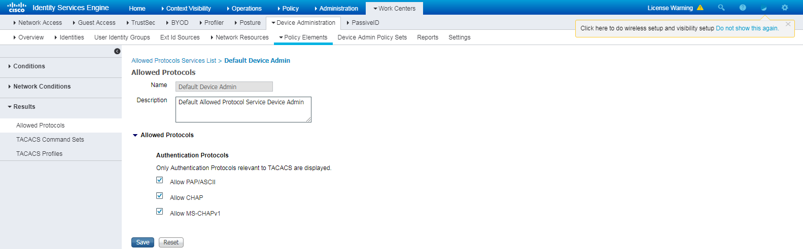
3. Configure authentication protocols:
a. On the top navigation bar, select Work Centers > Device Administration > Policy Elements.
b. From the left navigation pane, select Results > Allowed Protocols.
c. Use the default allowed protocols service named Default Device Admin.
Figure 15 Configuring authentication protocols
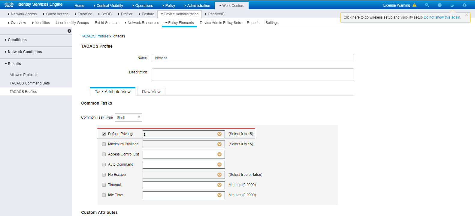
4. Configure a TACACS profile:
a. On the top navigation bar, select Work Centers > Device Administration > Policy Elements.
b. From the left navigation pane, select Results > TACACS Profiles.
c. Click Add.
d. On the page that opens, set the name to ldftacas, select Default Privilege, and set the default privilege to level 1.
e. Save the configuration.
Figure 16 Configuring a TACACS profile
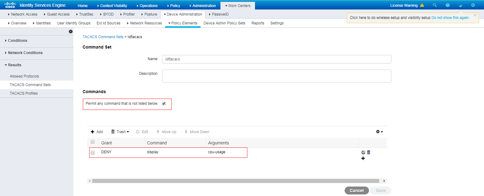
5. Configure a TACACS command set:
a. On the top navigation bar, select Work Centers > Device Administration > Policy Elements.
b. From the left navigation pane, select Results > TACACS Command Sets.
c. Click Add.
d. On the page that opens, set the name to ldftacacs. In the Commands area, select Permit any command that is not listed below and deny the display cpu-usage command.
e. Save the configuration.
Figure 17 Configuring a TACACS command set
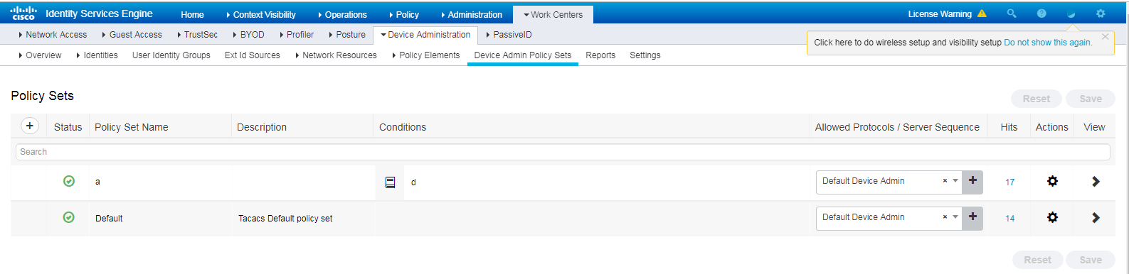
6. Configure an authentication and authorization policy set:
a. On the top navigation bar, select Work Centers > Device Administration > Device Admin Policy Sets.
b. Click the plus icon + under Policy Sets.
c. Set the policy set name to a.
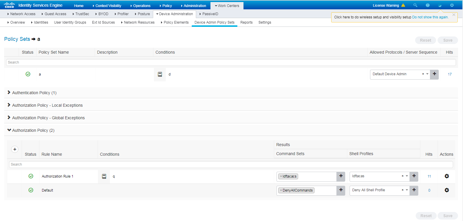
Figure 18 Configuring an authentication and authorization policy set
d. Click the icon in the View column for the authentication and authorization policy set named a.
e. In the Authorization Policy area, add an authorization policy named Authorization Rule 1. In the Results > Command Sets column for the authorization policy, select command set ldftacacs. In the Results > Shell Profiles column for the authorization policy, select TACACS profile ldftacas.
Figure 19 Adding an authorization policy
f. Save the configuration.
7. Enable device access authentication service:
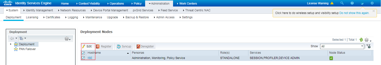
a. On the top navigation bar, select Administration > System > Deployment.
b. Select the ISE node, and then click Edit.
Figure 20 Selecting the ISE node and clicking Edit
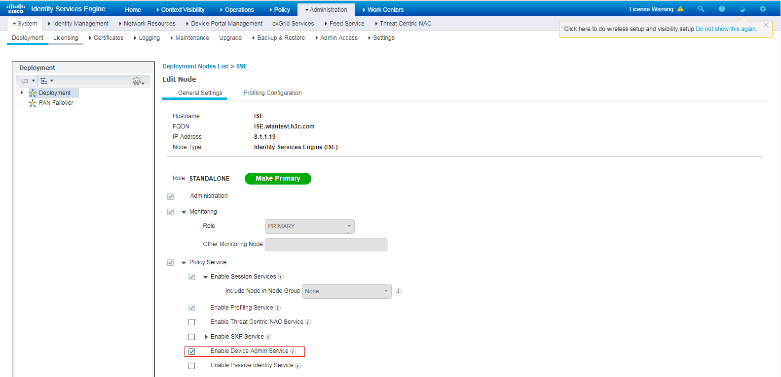
c. On the page that opens, select the Enable Device Admin Service option and save the configuration.
Figure 21 Editing the ISE node
Verifying the configuration
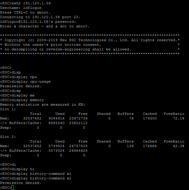
1. Verify that the client can log in to the AC through SSH after it provides the correct username and password. (Details not shown.)
2. Verify that the client can access only commands permitted by the level-1 role. For example, the client can access the display memory command. Verify that the client cannot access the display cpu-usage command.
Figure 22 Verifying the access permissions
Configuration files
#
hwtacacs scheme tac
primary authentication 8.1.1.19 key cipher $c$3$8zfqwa07HmNhvjWvEeixw5NGEGo82r/htRg=
primary authorization 8.1.1.19 key cipher $c$3$fARZu6PskfKoULCy46SHq0hVbNHakBUPleE=
primary accounting 8.1.1.19 key cipher $c$3$tBnfBlfHnO9YHBko2ZjMpzpuRqSyN3wdDPA=
user-name-format without-domain
nas-ip 191.2.1.56
#
domain system
authentication login hwtacacs-scheme tac
authorization login hwtacacs-scheme tac
accounting login none
authorization command hwtacacs-scheme tac
accounting command hwtacacs-scheme tac
#
public-key local create rsa
#
public-key local create dsa
#
ssh server enable
#
role default-role enable
#
line vty 0 31
authentication-mode scheme
command authorization
command accounting
