- Table of Contents
- Related Documents
-
| Title | Size | Download |
|---|---|---|
| 01-Hardware Information and Specifications.htm | 1.38 MB |
Contents
1 Product models and technical specifications
10/100/1000BASE-T autosensing Ethernet port
5G/2.5G/1000/100 BASE-T autosensing Ethernet port
Autosensing Ethernet port LEDs
1 Product models and technical specifications
Product models
This document is applicable to the FS5100-EI switch series. Table1-1 describes the FS5100-EI switch series models.
Table1-1 FS5100-EI switch series models
|
Switch series |
Model |
Product code |
|
|
FS5100-EI series |
Non-PoE switch |
FS5100-12S-EI |
LS-FS5100-12S-EI |
|
FS5100-12MS-EI |
LS-FS5100-12MS-EI |
||
|
FS5100-20MS-EI |
LS-FS5100-20MS-EI |
||
|
FS5100-52F-EI-PS |
LS-FS5100-52F-EI-PS |
||
|
PoE switch |
FS5100-8S-PWR-EI |
LS-FS5100-8S-PWR-EI |
|
|
FS5100-12S-PWR-EI |
LS-FS5100-12S-PWR-EI |
||
|
FS5100-12MS-PWR-EI |
LS-FS5100-12MS-PWR-EI |
||
|
FS5100-20MS-PWR-EI |
LS-FS5100-20MS-PWR-EI |
||
Technical specifications
Non-PoE switch models
Table1-2 Technical specifications for non-PoE switch models
|
Item |
FS5100-12S-EI |
FS5100-12MS-EI |
FS5100-20MS-EI |
FS5100-52F-EI-PS |
|
Dimensions (H × W × D) |
43.6 × 266 × 161 mm (17.17 × 104.72 × 63.39 in) |
43.6 × 266 × 161 mm (17.17 × 104.72 × 63.39 in) |
43.6 × 294 × 179 mm (17.17 × 115.75 × 70.47 in) |
43.6 × 440 × 400 mm (17.17 × 173.23 ×157.48 in) |
|
Weight |
≤ 1.3 kg (2.87 lb) |
≤ 1.3 kg (2.87 lb) |
≤ 1.6 kg (3.53 lb) |
≤ 7 kg (15.43 lb) |
|
Console port |
1 × serial console port |
|||
|
10/100/1000BASE-T autosensing Ethernet port |
8 |
8 |
16 |
2 (The two ports form combo interfaces with their corresponding SFP ports, respectively.) |
|
5G/2.5G/1000/100BASE-T autosensing Ethernet port |
N/A |
2 |
2 |
N/A |
|
SFP port |
N/A |
N/A |
N/A |
48 (The two highest-numbered SPF ports form combo interfaces with their corresponding 10/100/1000 BASE-T autosensing Ethernet ports, respectively.) |
|
SFP+ port |
4 |
2 |
2 |
4 |
|
Power interface (PI) |
N/A |
N/A |
N/A |
· 4 × 56 V PIs · 200 W load per PI · A maximum power supply distance of 200 m (656.17 ft) |
|
Input voltage |
· Rated voltage range: 100 VAC to 240 VAC @ 50 or 60 Hz · Max. voltage range: 90 VAC to 264 VAC@ 47 to 63 Hz |
|||
|
Minimum power consumption |
9 W |
10 W |
11 W |
· One power supply: 38 W · Two power supplies: 49 W |
|
Maximum power consumption |
15 W |
16 W |
20 W |
· One power supply: 1000 W · Two power supplies: 1000 W |
|
Melting current of power supply fuse |
3.15 A/250 V |
2 A/250 V |
2 A/250 V |
16 A/250 V |
|
Cooling system |
Passive cooling |
Passive cooling |
Passive cooling |
Built-in fans with left-to-right airflow |
|
Operating temperature |
–5ºC to +45ºC (23°F to 113°F) |
|||
|
Operating humidity |
5% to 95%, noncondensing |
|||
|
Installation compliance |
UL62368-1/EN62368-1/IEC62368-1/UL60950-1/IEC60950-1/GB4943.1 |
|||
PoE switch models
Table1-3 Technical specifications for PoE switch models
|
Item |
FS5100-8S-PWR-EI |
FS5100-12S-PWR-EI |
FS5100-12MS-PWR-EI |
FS5100-20MS-PWR-EI |
|
Dimensions (H × W × D) |
43.6 × 266 × 161 mm (17.17 × 104.72 × 63.39 in) |
43.6 × 266 × 161 mm (17.17 × 104.72 × 63.39 in) |
43.6 × 266 × 161 mm (17.17 × 104.72 × 63.39 in) |
43.6 × 294 × 179 mm (17.17 × 115.75 × 70.47 in) |
|
Weight |
≤ 1.5 kg (3.31 lb) |
≤ 1.5 kg (3.31 lb) |
≤ 1.5 kg (3.31 lb) |
≤ 2 kg (4.41 lb) |
|
Console port |
1 × serial console port |
|||
|
10/100/1000BASE-T autosensing Ethernet port |
4 |
8 |
8 |
16 |
|
5G/2.5G/1000/100BASE-T autosensing Ethernet port |
N/A |
N/A |
2 |
2 |
|
SFP+ port |
4 |
4 |
2 |
2 |
|
Input voltage |
· Rated voltage range: 100 VAC to 240 VAC @ 50 or 60 Hz · Maximum voltage range: 90 VAC to 264 VAC @ 47 Hz to 63 Hz |
|||
|
Maximum PoE power per port |
30 W |
30 W |
30 W (10/100/1000BASE-T autosensing Ethernet ports 1 and 2 do not support PoE.) |
30 W (10/100/1000BASE-T autosensing Ethernet ports 1 and 2 do not support PoE.) |
|
Total PoE power |
65 W |
125 W |
125 W |
125 W |
|
Power consumption (static) |
10 W |
12 W |
12 W |
13 W |
|
Power consumption (fully configured, including PoE power) |
90 W |
160 W |
160 W |
160 W |
|
Melting current of power supply fuse |
3.15 A/250 V |
6.3 A/250 V |
6.3 A/250 V |
6.3 A/250 V |
|
Cooling system |
Passive cooling |
Passive cooling |
Passive cooling |
Passive cooling |
|
Operating temperature |
–5ºC to +45ºC (23°F to 113°F) |
|||
|
Operating humidity |
5% to 95%, noncondensing |
|||
|
Installation compliance |
UL62368-1/EN62368-1/IEC62368-1/UL60950-1/IEC60950-1/GB4943.1 |
|||
2 Chassis views
FS5100-8S-PWR-EI
Figure2-1 Front panel
|
(1) 10/100/1000BASE-T autosensing Ethernet port |
|
|
(2) 10/100/1000BASE-T autosensing Ethernet port LED |
|
|
(3) SFP+ port LED |
(4) System status LED (SYS) |
|
(5) Mode LED (MODE) |
(6) LED mode switching button |
|
(7) Console port (CONSOLE) |
(8) SFP+ port |
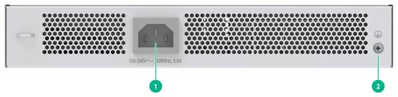
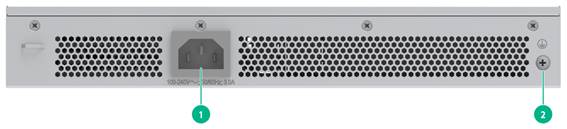
Figure2-2 Rear panel
|
(1) AC-input power receptacle |
(2) Grounding screw |
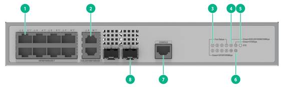
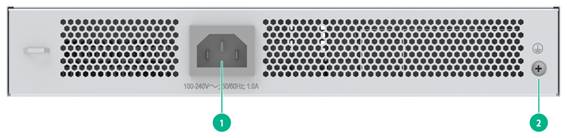
FS5100-12S-EI
Figure2-3 Front panel
|
(1) 10/100/1000BASE-T autosensing Ethernet port |
|
|
(2) 10/100/1000BASE-T autosensing Ethernet port LED |
|
|
(3) System status LED (SYS) |
(4) SFP+ port LED |
|
(5) Console port (CONSOLE) |
(6) SFP+ port |
Figure2-4 Rear panel
|
(1) AC-input power receptacle |
(2) Grounding screw |
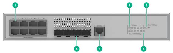
FS5100-12S-PWR-EI
Figure2-5 Front panel
|
(1) 10/100/1000BASE-T autosensing Ethernet port |
|
|
(2) 10/100/1000BASE-T autosensing Ethernet port LED |
|
|
(3) System status LED (SYS) |
(4) Mode LED (MODE) |
|
(5) SFP+ port LED |
(6) LED mode switching button |
|
(7) Console port (CONSOLE) |
(8) SFP+ port |
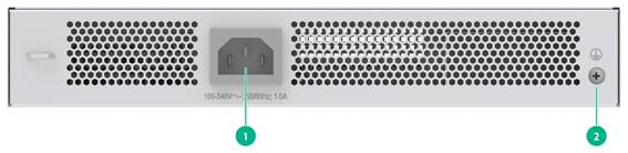
Figure2-6 Rear panel
|
(1) AC-input power receptacle |
(2) Grounding screw |
FS5100-12MS-EI
Figure2-7 Front panel
|
(1) 10/100/1000BASE-T autosensing Ethernet port |
|
|
(2) 5G/2.5G/1000/100BASE-T autosensing Ethernet port |
|
|
(3) 10/100/1000BASE-T autosensing Ethernet port LED |
|
|
(4) 5G/2.5G/1000/100BASE-T autosensing Ethernet port LED |
|
|
(5) System status LED (SYS) |
(6) SFP+ port LED |
|
(7) Console port (CONSOLE) |
(8) SFP+ port |
Figure2-8 Rear panel
|
(1) AC-input power receptacle |
(2) Grounding screw |
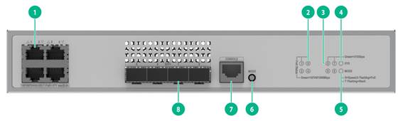
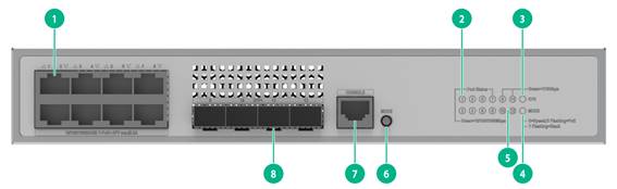
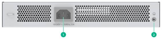
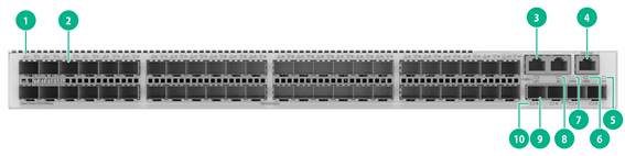
FS5100-12MS-PWR-EI
Figure2-9 Front panel
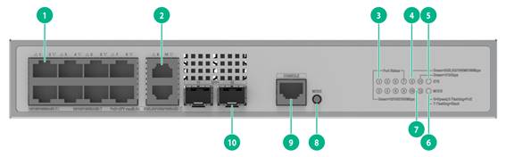
|
(1) 10/100/1000BASE-T autosensing Ethernet port |
|
|
(2) 5G/2.5G/1000/100BASE-T autosensing Ethernet port |
|
|
(3) 10/100/1000BASE-T autosensing Ethernet port LED |
|
|
(4) 5G/2.5G/1000/100BASE-T autosensing Ethernet port LED |
|
|
(5) System status LED (SYS) |
(6) Mode LED (MODE) |
|
(7) SFP+ port LED |
(8) LED mode switching button |
|
(9) Console port (CONSOLE) |
(10) SFP+ port |
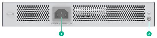
Figure2-10 Rear panel
|
(1) AC-input power receptacle |
(2) Grounding screw |
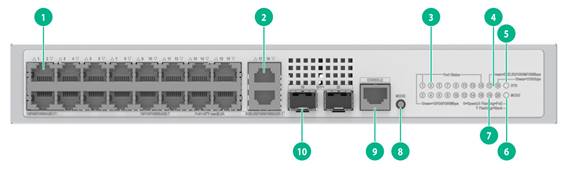
FS5100-20MS-EI
Figure2-11 Front panel

|
(1) 10/100/1000BASE-T autosensing Ethernet port |
|
|
(2) 5G/2.5G/1000/100BASE-T autosensing Ethernet port |
|
|
(3) 10/100/1000BASE-T autosensing Ethernet port LED |
|
|
(5) System status LED (SYS) |
(4) SFP+ port LED |
|
(6) 5G/2.5G/1000/100BASE-T autosensing Ethernet port LED |
|
|
(7) Console port (CONSOLE) |
(8) SFP+ port |
Figure2-12 Rear panel
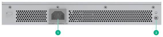
|
(1) AC-input power receptacle |
(2) Grounding screw |
FS5100-20MS-PWR-EI
Figure2-13 Front panel
|
(1) 10/100/1000BASE-T autosensing Ethernet port |
|
|
(2) 5G/2.5G/1000/100BASE-T autosensing Ethernet port |
|
|
(3) 10/100/1000BASE-T autosensing Ethernet port LED |
|
|
(4) SFP+ port LED |
(5) System status LED (SYS) |
|
(6) Mode LED (MODE) |
|
|
(7) 5G/2.5G/1000/100BASE-T autosensing Ethernet port LED |
|
|
(8) LED mode switching button |
(9) Console port (CONSOLE) |
|
(10) SFP+ port |
|
Figure2-14 Rear panel
|
(1) AC-input power receptacle |
(2) Grounding screw |
FS5100-52F-EI-PS
Figure2-15 Front panel
|
(1) SFP port LED |
(2) SFP port |
|
(3) 10/100/1000BASE-T autosensing Ethernet port |
|
|
(4) Console port (CONSOLE) |
(5) System status LED (SYS) |
|
(6) Power supply 2 status LED (PWR2) |
(7) Power supply 1 status LED (PWR1) |
|
(8) 10/100/1000BASE-T autosensing Ethernet port LED |
|
|
(9) SFP+ port |
(10) SFP+ port LED |
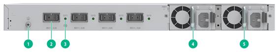
|
(1) Grounding screw |
(2) PI |
|
(3) PI LED |
(4) Removable power supply 1 |
|
(5) Removable power supply 2 |
|
|
|
NOTE: The FS5100-52F-EI-PS switch has two power supply slots on the rear panel and came with power supply slot PWR1 empty and power supply slot PWR2 installed with a filler panel. You can install one or two power supplies as needed. In Figure2-16, two PSR920-54A-B power supplies are installed in the power supply slots. |
3 Removable components
Only the FS5100-52F-EI-PS switch provides removable power supply slots, and you can use the PSR920-54A-B power supply to power the device.
One power supply can meet the power requirement of the switch. You can install two power supplies on the switch for 1+1 redundancy.
Table3-1 describes the power supply available for the FS5100-52F-EI-PS switch.
Table3-1 Power supply available for the FS5100-52F-EI-PS switch
|
For more information about the power supply, see H3C PSR920-54A-B Power Supply User Manual-APW100. |
|||
4 Ports and LEDs
Ports
Console port
Table4-1 Console port specifications
|
Item |
Specification |
|
Connector type |
RJ-45 |
|
Compliant standard |
EIA/TIA-232 |
|
Transmission baud rate |
9600 bps (default) to 115200 bps |
|
Services |
· Provides connection to an ASCII terminal. · Provides connection to the serial port of a local PC running terminal emulation program. |
|
Available switch models |
All switch models |
|
Restrictions and guidelines |
You cannot use the serial console port and micro USB console port at the same time. If you connect both ports at the same time, only the micro USB console port takes effect. |
10/100/1000BASE-T autosensing Ethernet port
Table4-2 10/100/1000BASE-T autosensing Ethernet port specifications
|
Item |
Specification |
|
Connector type |
RJ-45 |
|
Transmission rate, duplex mode, and auto MDI/MDI-X |
· 10 Mbit/s, half/full-duplex · 100 Mbit/s, half/full-duplex · 1000 Mbit/s, full-duplex · MDI/MDI-X, autosensing |
|
Max transmission distance |
100 m (328.08 ft) |
|
Available switch models |
All switch models |
|
Transmission medium |
Category-5 (or above) twisted pair cable |
|
Compatible standards |
· IEEE 802.3i · IEEE 802.3u, · IEEE 802.3ab |
5G/2.5G/1000/100 BASE-T autosensing Ethernet port
Table4-3 5G/2.5G/1000/100 BASE-T autosensing Ethernet port specifications
|
Item |
Description |
|
Connector type |
RJ-45 |
|
Transmission rate, duplex mode, and auto MDI/MDI-X |
· 100 Mbps, half/full-duplex · 1 Gbps, full-duplex · 2.5 Gbps, full-duplex · 5 Gbps, full-duplex · MDI/MDI-X, autosensing |
|
Max transmission distance |
· 5 G mode: 100 m (328.08 ft) over Category-5e or above twisted pair · 2.5 G mode: 200 m (656.17 ft) over Category-5e or above twisted pair · 1 G mode: 140 m (459.32 ft) over Category-5e or above twisted pair · 100 M mode: 100 m (328.084 ft) over Category-5e or above twisted pair NOTE: The maximum transmission distance depends on the target device and the twisted pair quality. |
|
Available switch models |
FS5100-12MS-EI, FS5100-12MS-PWR-EI, FS5100-20MS-EI, and FS5100-20MS-PWR-EI |
|
Transmission medium |
Category-5e (or above) twisted pair cable |
|
Compatible standards |
· IEEE 802.3ab · IEEE 802.3an |
SFP port
Table4-4 SFP port specifications
|
Item |
Specification |
|
Connector type |
SFP connector |
|
GE SFP transceiver modules and cables |
GE SFP transceiver modules and cables in Table4-5. |
|
Available switch models |
FS5100-52F-EI-PS |
|
Restrictions and guidelines |
To use transceiver modules with a maximum transmission distance greater than or equal to 80 km (49.71 miles), make sure the ambient temperature does not exceed 40°C (104°F). |
Table4-5 GE SFP transceiver modules and cables
|
GE SFP transceiver module/cable |
Central wavelength |
Connector |
Cable specifications |
Modal bandwidth (MHz*km) |
Max. transmission distance |
|
Copper SFP transceiver module |
|||||
|
SFP-GE-T |
N/A |
RJ-45 |
Twisted pair cable |
N/A |
100 m (328.08 ft) |
|
SFP-GE-T-D |
N/A |
RJ-45 |
Twisted pair cable |
N/A |
100 m (328.08 ft) |
|
Fiber SFP transceiver module |
|||||
|
SFP-GE-SX-MM850-A |
850 nm |
LC |
50/125 µm multi-mode optical fiber |
500 |
550 m (1804.46 ft) |
|
400 |
500 m (1640.42 ft) |
||||
|
62.5/125 µm multi-mode optical fiber |
200 |
275 m (902.23 ft) |
|||
|
160 |
220 m (721.78 ft) |
||||
|
SFP-GE-SX-MM850-D |
850 nm |
LC |
50/125 µm multi-mode optical fiber |
500 |
550 m (1804.46 ft) |
|
400 |
500 m (1640.42 ft) |
||||
|
62.5/125 µm multi-mode optical fiber |
200 |
275 m (902.23 ft) |
|||
|
160 |
220 m (721.78 ft) |
||||
|
SFP-GE-SX-MM850-S |
850 nm |
LC |
50/125 µm multi-mode optical fiber |
500 |
550 m (1804.46 ft) |
|
400 |
500 m (1640.42 ft) |
||||
|
62.5/125 µm multi-mode optical fiber |
200 |
275 m (902.23 ft) |
|||
|
160 |
220 m (721.78 ft) |
||||
|
SFP-GE-LX-SM1310-A |
1310 nm |
LC |
9/125 µm single-mode fiber |
N/A |
10 km (6.21 miles) |
|
50/125 µm multi-mode fiber |
500/400 |
550 m (1804.46 ft) |
|||
|
62.5/125 µm multi-mode fiber |
500 |
550 m (1804.46 ft) |
|||
|
SFP-GE-LX-SM1310-D |
1310 nm |
LC |
9/125 µm single-mode fiber |
N/A |
10 km (6.21 miles) |
|
SFP-GE-LX-SM1310-S |
1310 nm |
LC |
9/125 µm single-mode fiber |
N/A |
10 km (6.21 miles) |
|
SFP-GE-LH40-SM1310 |
1310 nm |
LC |
9/125 µm single-mode fiber |
N/A |
40 km (24.86 miles) |
|
SFP-GE-LH40-SM1310-D |
1310 nm |
LC |
9/125 µm single-mode fiber |
N/A |
40 km (24.86 miles) |
|
SFP-GE-LH40-SM1550 |
1550 nm |
LC |
9/125 µm single-mode fiber |
N/A |
40 km (24.86 miles) |
|
SFP-GE-LH80-SM1550 |
1550 nm |
LC |
9/125 μm single-mode fiber |
N/A |
80 km (49.71 miles) |
|
SFP-GE-LH80-SM1550-D |
1550 nm |
LC |
9/125 μm single-mode fiber |
N/A |
80 km (49.71 miles) |
|
SFP-GE-LH100-SM1550 |
1550 nm |
LC |
9/125 µm single-mode fiber |
N/A |
100 km (62.14 miles) |
|
SFP-GE-LX-SM1310-BIDI |
TX: 1310 nm RX: 1490 nm |
LC |
9/125 µm single-mode fiber |
N/A |
10 km (6.21 miles) |
|
SFP-GE-LX-SM1490-BIDI |
TX: 1490 nm RX: 1310 nm |
||||
|
SFP-GE-LH40-SM1310-BIDI |
TX: 1310 nm RX: 1550 nm |
LC |
9/125 µm single-mode fiber |
N/A |
40 km (24.86 miles) |
|
SFP-GE-LH40-SM1550-BIDI |
TX: 1550 nm RX: 1310 nm |
||||
|
SFP-GE-LH70-SM1490-BIDI |
TX: 1490 nm RX: 1550 nm |
LC |
9/125 µm single-mode fiber |
N/A |
70 km (43.50 miles) |
|
SFP-GE-LH70-SM1550-BIDI |
TX: 1550 nm RX: 1490 nm |
||||
|
SFP cable |
|||||
|
SFP-STACK-Kit |
N/A |
N/A |
SFP cable |
N/A |
1.5 m (4.92 ft) |
|
|
IMPORTANT: The SFP-GE-LX-SM1310-BIDI and SFP-GE-LX-SM1490-BIDI transceiver modules, the SFP-GE-LH40-SM1310-BIDI and SFP-GE-LH40-SM1550-BIDI transceiver modules, and the SFP-GE-LH70-SM1490-BIDI and SFP-GE-LH70-SM1550-BIDI transceiver modules must be used in pairs. For example, if one end uses an SFP-GE-LX-SM1310-BIDI transceiver module, the other end must use an SFP-GE-LX-SM1490-BIDI transceiver module. |
|
|
NOTE: · As a best practice, use H3C SFP/SFP+ transceiver modules or cables for the SFP+ ports. · The H3C SFP/SFP+ transceiver modules and cables available for the SFP+ ports are subject to change over time. For the most up-to-date list of H3C SFP/SFP+ transceiver modules and SFP+ cables available for the SFP+ ports, contact your H3C sales representative or technical support engineer. · For the specifications of the H3C SFP/SFP+ transceiver modules and cables, see H3C Transceiver Modules User Guide. |
SFP+ port
Table4-6 SPF+ port specification
|
Item |
Specification |
|
Connector type |
SFP+ connector |
|
GE SFP and 10-GE SFP+ transceiver modules and cables |
· GE SFP transceiver modules and cables in Table4-5. · 10-GE SFP+ transceiver modules in Table4-7. · SFP+ copper and fiber cables in Table4-8. |
|
Available switch models |
All switch models |
Table4-7 10-GE SFP+ transceiver modules
|
10-GE SFP+ transceiver module |
Central wavelength |
Connector |
Fiber |
Modal bandwidth (MHz*km) |
Max. transmission distance |
|
SFP-XG-SX-MM850-D |
850 nm |
LC |
50/125 µm multi-mode optical fiber |
2000 |
300 m (984.25 ft) |
|
500 |
82 m (269.03 ft) |
||||
|
400 |
66 m (216.54 ft) |
||||
|
62.5/125 µm multi-mode optical fiber |
200 |
33 m (108.27 ft) |
|||
|
160 |
26 m (85.30 ft) |
||||
|
SFP-XG-SX-MM850-E |
850 nm |
LC |
50/125 µm multi-mode optical fiber |
2000 |
300 m (984.25 ft) |
|
500 |
82 m (269.03 ft) |
||||
|
400 |
66 m (216.54 ft) |
||||
|
62.5/125 µm multi-mode optical fiber |
200 |
33 m (108.27 ft) |
|||
|
160 |
26 m (85.30 ft) |
||||
|
SFP-XG-SX-MM850-S |
850 nm |
LC |
50/125 µm multi-mode optical fiber |
2000 |
300 m (984.25 ft) |
|
500 |
82 m (269.03 ft) |
||||
|
400 |
66 m (216.54 ft) |
||||
|
62.5/125 µm multi-mode optical fiber |
200 |
33 m (108.27 ft) |
|||
|
160 |
26 m (85.30 ft) |
||||
|
SFP-XG-LX-SM1310-D |
1310 nm |
LC |
9/125 µm single-mode fiber |
N/A |
10 km (6.21 miles) |
|
SFP-XG-LX-SM1310-E |
1310 nm |
LC |
9/125 µm single-mode fiber |
N/A |
10 km (6.21 miles) |
|
SFP-XG-LX-SM1310-S |
1310 nm |
LC |
9/125 µm single-mode fiber |
N/A |
10 km (6.21 miles) |
|
SFP-XG-LH40-SM1550 |
1550 nm |
LC |
9/125 µm single-mode fiber |
N/A |
40 km (24.86 miles) |
|
SFP-XG-LH40-SM1550-D |
1550 nm |
LC |
9/125 µm single-mode fiber |
N/A |
40 km (24.86 miles) |
|
SFP-XG-LH80-SM1550 |
1550 nm |
LC |
9/125 µm single-mode fiber |
N/A |
80 km (49.71 miles) |
|
SFP-XG-LH80-SM1550-D |
1550 nm |
LC |
9/125 µm single-mode fiber |
N/A |
80 km (49.71 miles) |
|
SFP-XG-LX-SM1270-BIDI |
TX: 1270 nm RX: 1330 nm |
LC |
9/125 µm single-mode fiber |
N/A |
10 km (6.21 miles) |
|
SFP-XG-LX-SM1330-BIDI |
TX: 1330 nm RX: 1270 nm |
||||
|
SFP-XG-LH40-SM1270-BIDI |
TX: 1270 nm RX: 1330 nm |
LC |
9/125 µm single-mode fiber |
N/A |
40 km (24.86 miles) |
|
SFP-XG-LH40-SM1330-BIDI |
TX: 1330 nm RX: 1270 nm |
9/125 µm single-mode fiber |
N/A |
40 km (24.86 miles) |
|
|
IMPORTANT: The SFP-XG-LX-SM1270-BIDI and SFP-XG-LX-SM1330-BIDI transceiver modules and the SFP-XG-LH40-SM1270-BIDI and SFP-XG-LH40-SM1330-BIDI transceiver modules must be used in pairs. For example, if one end uses an SFP-XG-LX-SM1270-BIDI transceiver module, the other end must use an SFP-XG-LX-SM1330-BIDI transceiver module. |
Table4-8 SFP+ copper and fiber cables available for the SFP+ ports
|
Item |
Max transmission distance |
|
SFP+ copper cable |
|
|
LSWM1STK |
0.65 m (2.13 ft) |
|
LSWM2STK |
1.2 m (3.94 ft) |
|
LSWM3STK |
3 m (9.84 ft) |
|
LSTM1STK |
5 m (16.40 ft) |
|
SFP+ fiber cable |
|
|
SFP-XG-D-AOC-7M |
7 m (22.97 ft) |
|
SFP-XG-D-AOC-10M |
10 m (32.81 ft) |
|
SFP-XG-D-AOC-20M |
20 m (65.62 ft) |
Figure4-1 10-GE SFP+ cable
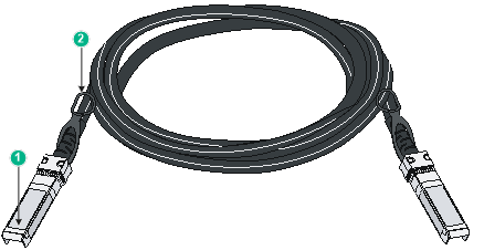
|
(1) Connector |
(2) Pull latch |
|
|
NOTE: · As a best practice, use H3C SFP/SFP+ transceiver modules or cables for the SFP+ ports. · The H3C SFP/SFP+ transceiver modules and cables available for the SFP+ ports are subject to change over time. For the most up-to-date list of H3C SFP/SFP+ transceiver modules and SFP+ cables available for the SFP+ ports, contact your H3C sales representative or technical support engineer. · For the specifications of the H3C SFP/SFP+ transceiver modules and cables, see H3C Transceiver Modules User Guide. |
LEDs
System status LED
The system status LED shows the operating status of the switch.
Table4-9 System status LED description
|
LED mark |
Status |
Description |
|
SYS |
Steady yellow |
Boot ROM booting stage. |
|
Steady green |
Linux kernel booting stage, or the switch has started up correctly. |
|
|
Flashing green (1 Hz) |
Software image loading and decompressing stage, or software booting stage. |
|
|
Flashing red (3 Hz) |
The switch has failed POST or the switch is faulty. |
|
|
Off |
The switch is powered off or has not started up correctly. |
Power supply status LED
The FS5100-52F-EI-PS switch provides PWR1 and PWR2 LEDs on the front panel to indicate the operating status of the power supplies.
Table4-10 Removable power supply status LED description
|
LED mark |
Status |
Description |
|
PWR1/PWR2 |
Steady green |
A power supply is installed in the power supply slot, and the power supply is outputting power correctly. |
|
Steady yellow |
A power supply is installed in the power supply slot, but the power supply is faulty or not powered on. |
|
|
Off |
No power supply is installed in the power supply slot. |
Mode LED (MODE)
Each PoE switch provides a mode LED (MODE). The mode LED works in conjunction with the Ethernet port LEDs to indicate the operating state of the Ethernet ports and the switch.
You can use the LED mode switching button to change the indication of the mode LED.
Table4-11 Description for the mode LED
|
LED mark |
Status |
Description |
|
Mode LED (MODE) |
Steady green |
The Ethernet port LEDs are showing link state of the ports. |
|
Flashing green |
The Ethernet port LEDs are showing the PoE status of the ports. |
|
|
Flashing yellow |
The Ethernet port LEDs work in conjunction to indicate the IRF member ID of the switch. For example, if the LED for port 5 is steady green, the IRF member ID of the switch is 5. |
SFP/SFP+ port LED
Table4-12 SFP/SFP+ port LED description
|
Status |
Description |
|
Steady green |
A link is present on the port. |
|
Flashing green |
The port is sending or receiving data. |
|
Off |
· No link is present on the port. · The mode LED is operating in PoE mode. |
Autosensing Ethernet port LEDs
On a PoE switch, the Ethernet port LEDs work in conjunction with the mode LED to indicate the operating state of the Ethernet ports and the switch from different aspects. Table4-13 describes the Ethernet port LEDs on a PoE switch.
Table4-14 describes the Ethernet port LEDs on a non-PoE switch.
This section is available for the following Ethernet port LEDs:
· 10/100/1000BASE-T autosensing Ethernet port LEDs
· 5G/2.5G/1000BASE-T autosensing Ethernet port LEDs
Table4-13 Ethernet port LED description for PoE switch models
|
Mode LED status |
Ethernet port LED status |
Description |
|
Steady green (Link/Active mode) |
Steady green |
A link is present on the port. |
|
Flashing green |
The port is sending or receiving data. |
|
|
Off |
No link is present on the port. |
|
|
Flashing green (PoE mode) |
Steady green |
PoE power supply is normal. |
|
Flashing green (1 Hz) |
· The maximum PoE power provided by the port does not meet the power requirement of the PD. · PoE power supply overcurrent, overvoltage, or short-circuit has occurred. · The remaining power of the switch does not meet the power supply requirement of the port. |
|
|
Off |
The port is not connected to a PD or PoE is not enabled on the port. |
|
|
Flashing yellow (IRF mode) |
Steady green |
The Ethernet port LEDs on the switch work in conjunction to indicate the IRF member ID of the switch. For example, if the LED for port 5 is steady green and the other port LEDs are off, the IRF member ID of the switch is 5. |
Table4-14 Ethernet port LED description for non-PoE switch models
|
Ethernet port LED status |
Description |
|
Steady green |
A link is present on the port. |
|
Flashing green |
The port is sending or receiving data. |
|
Off |
No link is present on the port. |
PI LED
The switch provides PI LEDs to indicate the operating status of the PIs.
Table4-15 PI LED description
|
LED mark |
Status |
Description |
|
OUT1 OUT2 OUT3 OUT4 |
On |
The PI is outputting power correctly. |
|
Off |
Power output failure has occurred on the PI. |
