- Table of Contents
- Related Documents
-
| Title | Size | Download |
|---|---|---|
| 01-Load balancing configuration | 1.72 MB |
Contents
Configuring server load balancing
Restrictions: Hardware compatibility with server load balancing
Restrictions and guidelines: Server load balancing configuration
Restrictions: Licensing requirements for server load balancing
Server load balancing tasks at a glance
Relationship between configuration items
Adding and configuring a server farm member
Configuring scheduling algorithms for a server farm
Setting the availability criteria
Enabling the slow online feature
Configuring intelligent monitoring
Configuring the action to take when a server farm is busy
Specifying a fault processing method
Creating a real server and specifying a server farm
Specifying an IP address and port number
Configuring the bandwidth and connection parameters
Enabling the slow offline feature
Disabling VPN instance inheritance
Virtual server tasks at a glance for Layer 4 server load balancing
Virtual server tasks at a glance for Layer 7 server load balancing
Configuring a TCP virtual server to operate at Layer 7
Specifying the VSIP and port number
Configuring the bandwidth and connection parameters
Enabling per-packet load balancing for UDP traffic
Configuring the HTTP redirection feature
Configuring the MySQL database version
Specifying the login username and password of the MySQL database
Enabling read/write separation for the MySQL database
Specifying a parameter profile
Specifying a protection policy
Applying an LB connection limit policy
Specifying a DPI application profile
Configuring external link proxy
Binding a VRRP group to a virtual server
Enabling IP address advertisement for a virtual server
Specifying an interface for sending gratuitous ARP packets and ND packets
Configuring the content to be output by using the fast log output feature
Creating a match rule that references an LB class
Creating a source IP address match rule
Creating an interface match rule
Creating a user group match rule
Creating a TCP payload match rule
Creating an HTTP content match rule
Creating an HTTP cookie match rule
Creating an HTTP header match rule
Creating an HTTP URL match rule
Creating an HTTP method match rule
Creating an HTTP version match rule
Creating a MySQL statement match rule
Creating a RADIUS attribute match rule
Configuring a forwarding LB action
Configuring a modification LB action
Specifying a response file for matching HTTP requests
Specifying a response file used upon load balancing failure
About configuring an LB policy
Specifying the default LB action
Sticky group tasks at a glance for Layer 4 server load balancing
Sticky group tasks at a glance for Layer 7 server load balancing
Configuring the IP sticky method
Configuring the TCP payload sticky method
Configuring the UDP passive sticky method
Configuring the HTTP content sticky method
Configuring the HTTP cookie sticky method
Configuring the HTTP header sticky method
Configuring HTTP passive sticky methods
Configuring the HTTP or UDP payload sticky method
Configuring the RADIUS attribute sticky method
Configuring the SIP call ID sticky method
Configuring the SSL sticky method
Configuring the timeout timer for sticky entries
Configuring the match scope for sticky entries
Ignoring the limits for sessions that match sticky entries
Enabling stickiness-over-busyness
Configuring a parameter profile
Parameter profile tasks at a glance
Configuring the ToS field in IP packets sent to the client
Configuring the maximum local window size for TCP connections
Configuring the idle timeout for TCP connections
Configuring the TIME_WAIT state timeout time for TCP connections
Configuring the retransmission timeout time for SYN packets
Configuring the TCP keepalive parameters
Configuring the FIN-WAIT-1 state timeout time for TCP connections
Configuring the FIN-WAIT-2 state timeout time for TCP connections
Setting the MSS for the LB device
Inserting the client IP address into the specified TCP option
Removing the specified TCP option from TCP packet headers
Configuring the TCP option for SNAT
Configuring the TCP payload match parameters
Enabling load balancing for each HTTP request
Configuring connection reuse between the LB device and the server
Modifying the header in each HTTP request or response
Disabling case sensitivity matching for HTTP
Configuring the maximum length to parse the HTTP content
Configuring secondary cookie parameters
Specifying the action to take when the header of an HTTP packet exceeds the maximum length
Configuring the maximum size of the HTTP content
Configuring the cookie encryption feature
Configuring the HTTP compression feature
Configuring the HTTP statistics feature
Configuring a protection policy
About configuring a protection policy
Protection policy tasks at a glance
Configuring a protection action
Configuring an LB probe template
About configuring an LB probe template
Configuring a TCP-RST LB probe template
Configuring a TCP zero-window LB probe template
Configuring an HTTP passive LB probe template
Configuring a custom-monitoring LB probe template
Configuring a SNAT global policy
About configuring a SNAT global policy
NAT global policy tasks at a glance
Configure a translation mode for the SNAT global policy
Setting the priority of the SNAT global policy
Specifying a source IP address object group for address translation
Specifying a destination IP address object group for address translation
Specifying a service object group for address translation
Specifying a VPN instance for the SNAT global policy
Enabling the SNAT global policy
Configuring an LB connection limit policy
Performing a load balancing test
About performing a load balancing test
Performing an IPv4 load balancing test
Performing an IPv6 load balancing test
Enabling load balancing logging
Enabling load balancing basic logging
Enabling load balancing NAT logging
Displaying and maintaining server load balancing
Server load balancing configuration examples
Example: Configuring basic Layer 4 server load balancing
Example: Configuring Layer 4 server load balancing hot backup
Example: Configuring basic Layer 7 server load balancing
Example: Configuring Layer 7 server load balancing SSL termination
Configuring outbound link load balancing
About outbound link load balancing
Outbound link load balancing tasks at a glance
Relationship between configuration items
Adding and configuring a link group member
Configuring a scheduling algorithm for a link group
Setting the availability criteria
Enabling the slow online feature
Specifying a fault processing method
Configuring the proximity feature
Creating a link and specifying a link group
Specifying an outbound next hop for a link
Specifying an outgoing interface for a link
Configuring the bandwidth and connection parameters
Enabling the slow offline feature
Setting the link cost for proximity calculation
Setting the bandwidth ratio and maximum expected bandwidth
Disabling VPN instance inheritance for a link
Virtual server tasks at a glance
Specifying the VSIP and port number
Specifying a parameter profile
Configuring the bandwidth and connection parameters
Enabling the link protection feature
Enabling bandwidth statistics collection by interfaces
Specifying a DPI application profile
Creating a match rule that references an LB class
Creating a source IP address match rule
Creating a destination IP address match rule
Creating an input interface match rule
Creating a user group match rule
Creating a domain name match rule
Creating an application group match rule
Configuring a forwarding LB action
Configuring the ToS field in IP packets sent to the server
Specifying the default LB action
Sticky group tasks at a glance
Configuring the IP sticky method
Configuring the timeout time for sticky entries
Ignoring the limits for sessions that match sticky entries
Enabling stickiness-over-busyness
Configuring a parameter profile
About configuring a parameter profile
Configuring the ToS field in IP packets sent to the client
About configuring ISP information
Configuring ISP information manually
Setting the aging time for DNS cache entries
Performing a load balancing test
About performing a load balancing test
Performing an IPv4 load balancing test
Performing an IPv6 load balancing test
Enabling load balancing logging
Enabling load balancing basic logging
Enabling load balancing link flow logging
Enabling load balancing NAT logging
Enabling load balancing link busy state logging
Displaying and maintaining outbound link load balancing
Outbound link load balancing configuration examples
Example: Configuring outbound link load balancing
Configuring transparent DNS proxies
Transparent DNS proxy on the LB device
Transparent DNS proxy tasks at a glance
Configuring a transparent DNS proxy
Transparent DNS proxy tasks at a glance
Creating a transparent DNS proxy
Specifying an IP address and port number
Specifying the default DNS server pool
Enabling the link protection feature
Enabling the transparent DNS proxy
Adding and configuring a DNS server pool member
Configuring a scheduling algorithm for a DNS server pool
Creating a DNS server and specifying a DNS server pool
Specifying an IP address and port number
Enabling the device to automatically obtain the IP address of a DNS server
Associating a link with a DNS server
Specifying an outbound next hop for a link
Specifying an outgoing interface for a link
Configuring the maximum bandwidth
Setting the bandwidth ratio and maximum expected bandwidth
Creating a match rule that references an LB class
Creating a source IP address match rule
Creating a destination IP address match rule
Creating a domain name match rule
Configuring a forwarding LB action
Configuring the ToS field in IP packets sent to the DNS server
Specifying the default LB action
Sticky group tasks at a glance
Configuring the IP sticky method
Configuring the timeout time for sticky entries
Enabling load balancing logging
Enabling load balancing NAT logging
Enabling load balancing link busy state logging
Displaying and maintaining transparent DNS proxy
Transparent DNS proxy configuration examples
Example: Configuring transparent DNS proxy
Configuring inbound link load balancing
About inbound link load balancing
Inbound link load balancing on the LB device
Restrictions and guidelines: Inbound link load balancing configuration
Inbound link load balancing tasks at a glance
DNS listener tasks at a glance
Specifying an IP address and a port number for a DNS listener
Enabling the DNS listening feature
Specifying the processing method for DNS mapping search failure
Specifying a domain name for a DNS mapping
Specifying a virtual server pool for a DNS mapping
Setting the TTL for DNS records
Enabling the DNS mapping feature
Configuring a virtual server pool
Virtual server pool tasks at a glance
Creating a virtual server pool
Specifying scheduling algorithms for a virtual server pool
Enabling the link protection feature
Specifying the outbound next hop for the LB link
Setting the bandwidth ratio and maximum expected bandwidth
Configuring a DNS forward zone
DNS forward zone tasks at a glance
Configuring a resource record of the specified type
Configuring an SOA resource record
Setting the TTL for resource records
Configuring a DNS reverse zone
Enabling load balancing link busy state logging
Performing a load balancing test
About performing a load balancing test
Performing an IPv4 load balancing test
Performing an IPv6 load balancing test
Setting the maximum number of DNS request parse failures to be recorded
Configuring the types of DNS request parse failures to be recorded
Displaying and maintaining inbound link load balancing
Inbound link load balancing configuration examples
Example: Configuring inbound link load balancing
Load balancing overview
Load balancing (LB) is a cluster technology that distributes services among multiple network devices or links.
Advantages of load balancing
Load balancing has the following advantages:
· High performance—Improves overall system performance by distributing services to multiple devices or links.
· Scalability—Meets increasing service requirements without compromising service quality by easily adding devices or links.
· High availability—Improves overall availability by using backup devices or links.
· Manageability—Simplifies configuration and maintenance by centralizing management on the load balancing device.
· Transparency—Preserves the transparency of the network topology for end users. Adding or removing devices or links does not affect services.
Load balancing types
LB includes the following types:
· Server load balancing—Data centers generally use server load balancing for networking. Network services are distributed to multiple servers or firewalls to enhance the processing capabilities of the servers or firewalls.
· Link load balancing—Link load balancing applies to a network environment where there are multiple carrier links to implement dynamic link selection. This enhances link utilization. Link load balancing supports IPv4 and IPv6, but does not support IPv4-to-IPv6 packet translation. Link load balancing is classified into the following types based on the direction of connection requests:
¡ Outbound link load balancing—Load balances traffic among the links from the internal network to the external network.
¡ Inbound link load balancing—Load balances traffic among the links from the external network to the internal network.
¡ Transparent DNS proxy—Load balances DNS requests among the links from the internal network to the external network.
Configuring server load balancing
About server load balancing
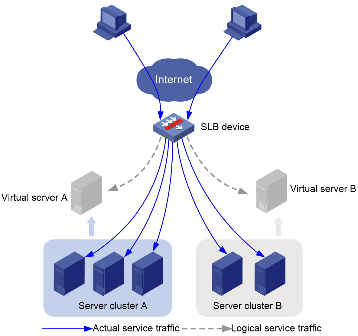
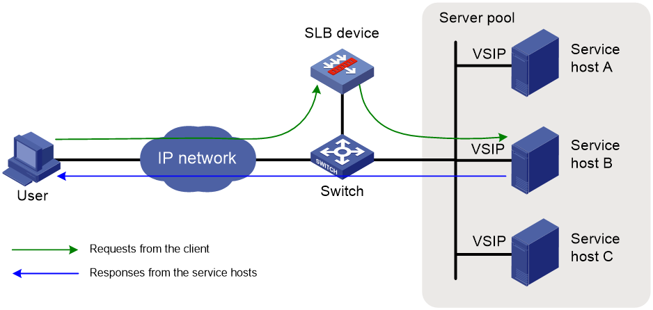
Server load balancing (SLB) appropriately distributes user traffic to multiple servers for processing to improve server resource utilization and user experience.
As shown in Figure 1, you can configure SLB by creating a virtual server with multiple real servers and advertising the virtual server IP address. When user traffic accesses the virtual server, SLB assigns user traffic to the optimal server based on the predefined scheduling algorithm and LB policy settings.
Figure 1 Server load balancing network diagram
Basic concepts
· Virtual server—Logical server through which the SLB device provides services. A virtual server is uniquely identified by protocol type, IP address, and port number. The SLB device processes only the traffic that matches the virtual server.
· Real server—Physical server that processes user requests.
· Server farm—Group of real servers that provide the same service.
Workflow
Figure 2 shows the SLB workflow.
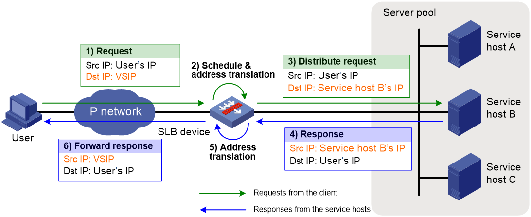
SLB works as follows:
1. A client sends a request with the VSIP as the destination to the SLB device.
2. The SLB device selects a real server based on the health monitoring method, sticky method, LB policy, and scheduling algorithm settings. Then, the SLB device replaces the destination IP address in the request with the IP address of the selected real server.
3. The SLB device forwards the request to the real server.
4. The real server receives and processes the request, and then sends a response to the client.
5. The SLB device receives the response and then replaces the source IP address in the response with the VSIP.
6. The SLB device forwards the request to the device.
Server load balancing types
Server load balancing is classified into Layer 4 server load balancing and Layer 7 server load balancing.
· Layer 4 server load balancing—Identifies network layer and transport layer information, and is implemented based on streams. It distributes packets in the same stream to the same server. Layer 4 server load balancing cannot distribute Layer 7 services based on contents.
· Layer 7 server load balancing—Identifies network layer, transport layer, and application layer information, and is implemented based on contents. It analyzes packet contents, distributes packets one by one based on the contents, and distributes connections to the specified server according to the predefined policies. Layer 7 server load balancing applies load balancing services to a large scope.
Deployment modes
Gateway mode
As shown in Figure 3, the SLB device is deployed on the path between the client and the real servers. All requests and responses go through the SLB device. Upon receiving a request, the SLB device selects a real server for the request based on the health monitoring method, sticky method, LB policy, and scheduling algorithm settings. Then, the SLB device replaces the destination IP address in the request with the IP address of the selected real server. Upon receiving the response, the SLB device replaces the source IP address in the response with the VSIP.
The gateway mode requires you to configure the default gateway or static routes on the real servers for the SLB device to receive packets destined for the client.
The gateway mode changes the existing topology, so that it applies to only the scenarios with simple network configuration.
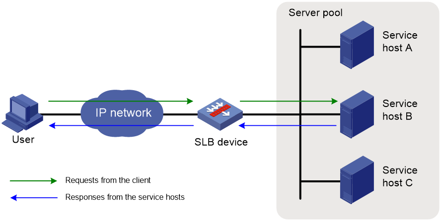
Out-of-path mode
As shown in Figure 4, the SLB device is attached to the core switch. All requests and responses go through the SLB device.
Upon receiving a request, the SLB device selects a real server for the request based on the health monitoring method, sticky method, LB policy, and scheduling algorithm settings. Then, the SLB device replaces the destination IP address in the request with the IP address of the selected real server. Upon receiving the response, the SLB device replaces the source IP address in the response with the VSIP.
This deployment mode requires you to configure the default gateway or static routes on the real servers for the SLB-attached core switch to receive packets destined for the client.
This deployment mode does not change the existing topology and provides flexibility.
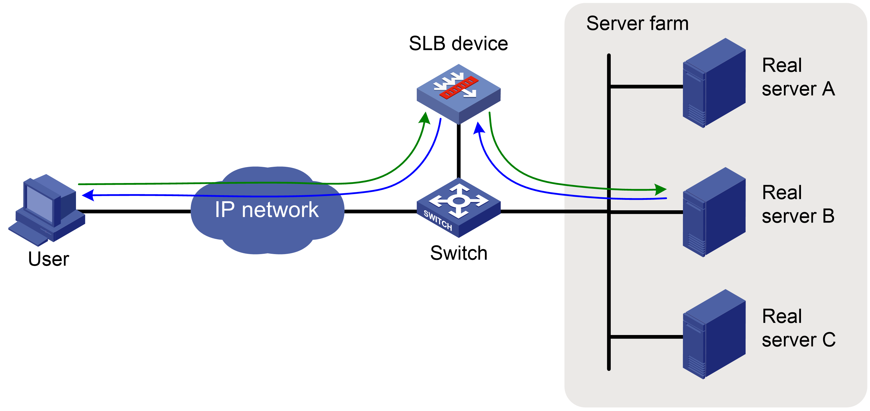
Direct server return (DSR) mode
As shown in Figure 5, the SLB device is attached to the core switch, and communicates with the real servers at Layer 2. Only client requests go through the SLB device. Upon receiving a request, the SLB device selects a real server for the request based on the health monitoring method, sticky method, LB policy, and scheduling algorithm settings. At this time, the source IP address, destination IP address, and the destination MAC address in the request are the client IP address, VSIP, and real server MAC address, respectively. The real server receives and processes the request, and then sends the response directly to the client. At this time, the source IP address and destination IP in the response are the VSIP and client IP address, respectively.
The DSR mode requires you to configure the default gateway or static routes on the real servers for the egress gateway to receive packets destined for the client. Additionally, you must specify the loopback address for the real servers as the VSIP.
The DSR mode does not change the existing topology. It applies to the scenarios with large amount of service traffic (such as video services), where the responses do not need to go through the SLB device.
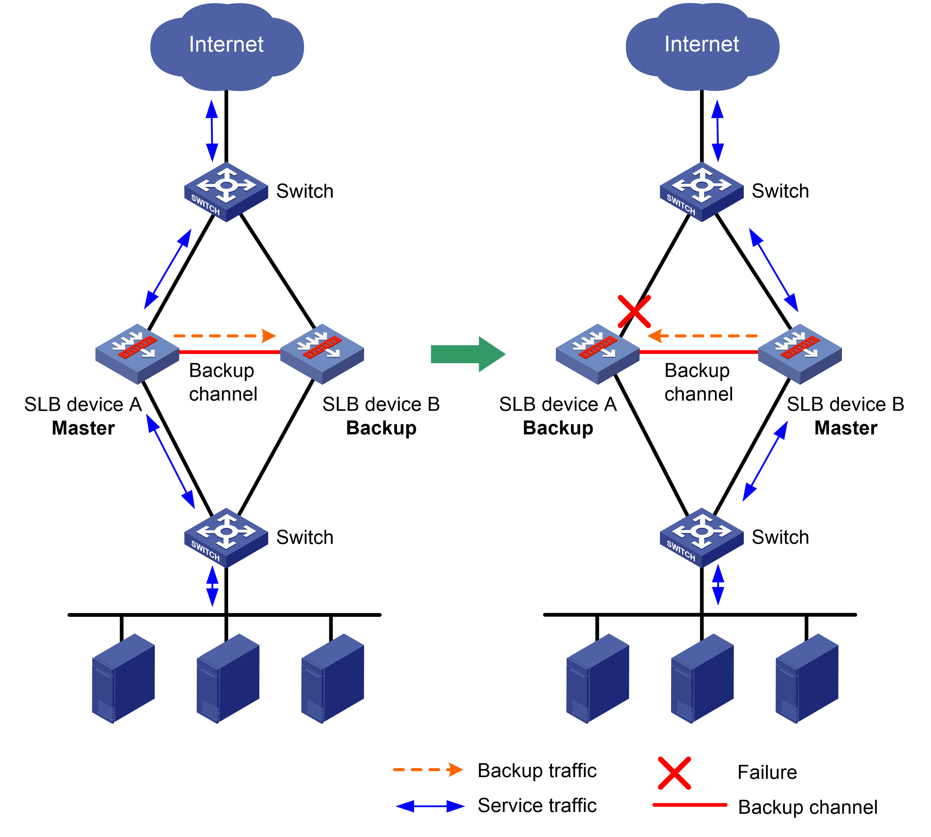
High availability for SLB
In a network with only one SLB device, once the SLB device fails, the client cannot access the real servers. Adopting the hot backup networking solves this issue and ensures service continuity. The hot backup feature supports the active/standby mode, dual-active mode, and cluster mode. For more information about hot backup, see High Availability Configuration Guide.
Active/standby mode
In this mode, two SLB devices in an internal network or data center form a hot backup system. One device is active to process services, and the other device stands by. When an interface or link on the active device fails or when the active device fails, the standby device becomes active to process services.
Figure 6 Active/standby mode of hot backup
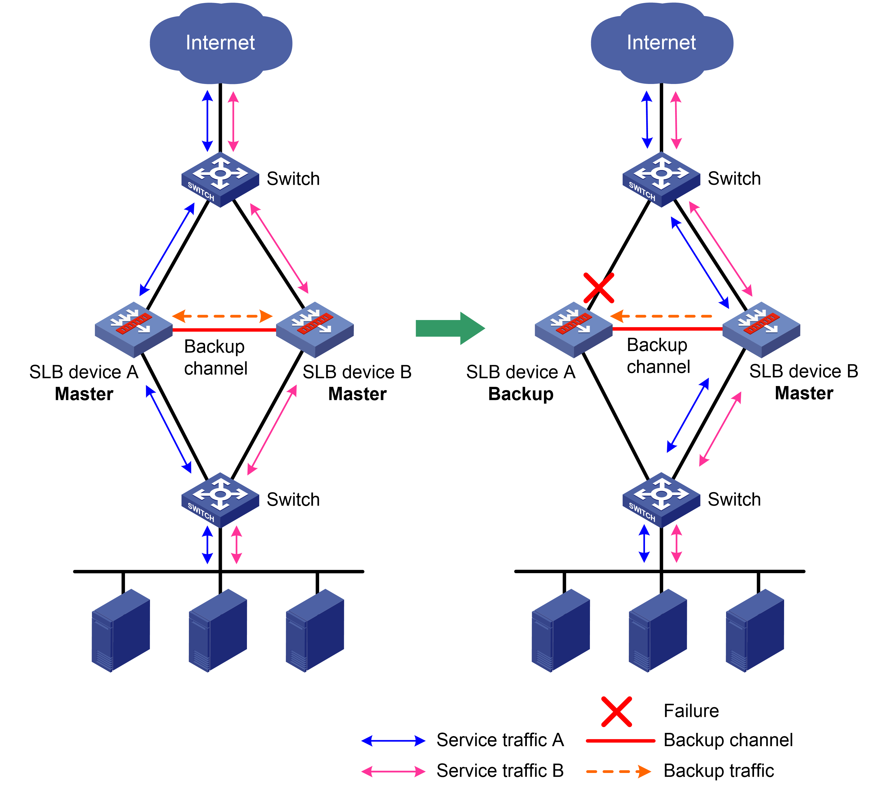
Dual-active mode
In this mode, two SLB devices in an internal network or data center form a hot backup system. Both devices process services to increase capability of the hot backup system. When one device fails, its traffic is switched to the other device for forwarding.
Figure 7 Dual-active mode of hot backup
Restrictions: Hardware compatibility with server load balancing
|
F1000 series |
Models |
Server load balancing compatibility |
|
F1000-X-G5 series |
F1000-A-G5, F1000-C-G5, F1000-C-G5-LI, F1000-E-G5, F1000-H-G5, F1000-S-G5 |
Yes |
|
F1000-X-G3 series |
F1000-A-G3, F1000-C-G3, F1000-E-G3, F1000-S-G3 |
Yes |
|
F1000-X-G2 series |
F1000-A-G2, F1000-C-G2, F1000-E-G2, F1000-S-G2 |
Yes |
|
F1000-9X0-AI series |
F1000-9390-AI, F1000-9385-AI, F1000-9380-AI, F1000-9370-AI, F1000-9360-AI, F1000-9350-AI, F1000-9330-AI, F1000-9320-AI, F1000-990-AI, F1000-980-AI, F1000-970-AI, F1000-960-AI, F1000-950-AI, F1000-930-AI, F1000-920-AI |
Yes |
|
F1000-910-AI, F1000-905-AI |
No |
|
|
F1000-C83X0 series |
F1000-C8395, F1000-C8390, F1000-C8385, F1000-C8380, F1000-C8370, F1000-C8360, F1000-C8350, F1000-C8330 |
Yes |
|
F1000-C81X0 series |
F1000-C8180, F1000-C8170, F1000-C8160, F1000-C8150, F1000-C8130, F1000-C8120, F1000-C8110 |
Yes |
|
|
No |
|
|
F1000-7X0-HI series |
F1000-770-HI, F1000-750-HI, F1000-740-HI, F1000-730-HI |
Yes |
|
F1000-720-HI, F1000-710-HI |
No |
|
|
F1000-C-X series |
F1000-C-EI, F1000-C-HI, F1000-C-XI, F1000-E-XI |
Yes |
|
F1000-V series |
F1000-E-VG |
Yes |
|
F1000-S-VG |
No |
|
|
SecBlade IV |
LSPM6FWD8, LSQM2FWDSC8 |
Yes |
|
F100 series |
Models |
Server load balancing compatibility |
|
F100-X-G5 series |
F100-A-G5, F100-E-G5 |
Yes |
|
F100-C-G5, F100-M-G5, F100-S-G5 |
No |
|
|
F100-X-G3 series |
F100-A-G3, F100-E-G3 |
Yes |
|
F100-C-G3, F100-M-G3, F100-S-G3 |
No |
|
|
F100-X-G2 series |
F100-A-G2, F100-E-G2 |
Yes |
|
F100-C-G2, F100-M-G2, F100-S-G2 |
No |
|
|
F100-WiNet series |
F100-A80-WiNet, F100-A91-WiNet, F100-A81-WiNet |
Yes |
|
F100-C80-WiNet, F100-C60-WiNet, F100-C50-WiNet, F100-S80-WiNet |
No |
|
|
F100-C-A series |
F100-C-A6, F100-C-A5, F100-C-A3, F100-C-A2, F100-C-A1, F100-C-A6-WL, F100-C-A5-W, F100-C-A3-W |
No |
|
F100-X-XI series |
F100-A-EI, F100-A-HI, F100-A-SI, F100-E-EI |
Yes |
|
F100-C-EI, F100-C-HI, F100-C-XI, F100-S-HI, F100-S-XI |
No |
Restrictions and guidelines: Server load balancing configuration
After you configure the NAT internal server feature for the interface by which the device connects to the client, the device performs server load balancing on the translated packets. For more information about the NAT internal server feature, see NAT in Layer 3—IP Services Configuration Guide.
Restrictions: Licensing requirements for server load balancing
You can configure server load balancing only after you purchase and install the appropriate license. For information about licensing, see license management in Fundamentals Configuration Guide.
Server load balancing tasks at a glance
Relationship between configuration items
Figure 8 shows the relationship between the following configuration items:
· Server farm—A collection of real servers that contain similar content. A sever farm can be referenced by a virtual server or an LB action.
· Real server—An entity on the LB device to process user services.
· Virtual server—A virtual service provided by the LB device to determine whether to perform load balancing for packets received on the LB device. Only the packets that match a virtual server are load balanced.
· LB class—Classifies packets to implement load balancing based on packet type.
· LB action—Drops, forwards, or modifies packets.
· LB policy—Associates an LB class with an LB action. An LB policy can be referenced by a virtual server.
· Sticky group—Uses a sticky method to distribute similar sessions to the same real server. A sticky group can be referenced by a virtual server or an LB action.
· Parameter profile—Defines advanced parameters to process packets. A parameter profile can be referenced by a virtual server.
Figure 8 Relationship between the main configuration items

Tasks at a glance
To configure server load balancing, perform the following tasks:
3. Configuring a virtual server
4. (Optional.) Configuring an LB policy
5. (Optional.) Configuring a sticky group
6. (Optional.) Configuring templates and policies
¡ Configuring a parameter profile
¡ Configuring a protection policy
¡ Configuring an LB probe template
¡ Configuring an LB connection limit policy
7. (Optional.) Configuring a SNAT global policy
8. (Optional.) Configuring the ALG feature
9. (Optional.) Reloading a response file
10. (Optional.) Performing a load balancing test
11. (Optional.) Configuring SNMP notifications and logging for load balancing
¡ Enabling load balancing logging
Configuring a server farm
You can add real servers that contain similar content to a server farm to facilitate management.
Server farm tasks at a glance
The server farm configuration tasks for Layer 4 and Layer 7 server load balancing are the same.
To configure a server farm, perform the following tasks:
2. (Optional.) Adding and configuring a server farm member
3. Configuring scheduling algorithms for a server farm
4. Configuring NAT
Choose the following tasks as needed:
5. Setting the availability criteria
6. (Optional.) Enabling the slow online feature
7. (Optional.) Configuring health monitoring
8. (Optional.) Configuring custom monitoring
9. (Optional.) Configuring intelligent monitoring
10. (Optional.) Configuring the action to take when a server farm is busy
11. (Optional.) Specifying a fault processing method
Creating a server farm
1. Enter system view.
system-view
2. Create a server farm and enter server farm view.
server-farm server-farm-name
3. (Optional.) Configure a description for the server farm.
description text
By default, no description is configured for the server farm.
Adding and configuring a server farm member
About this task
Perform this task to create a server farm member or add an existing real server as a server farm member in server farm view. You can also specify a server farm for a real server in real server view to achieve the same purpose (see "Creating a real server and specifying a server farm").
After adding a server farm member, you can configure the following parameters and features for the real server in the server farm:
· Weight.
· Priority.
· Connection limits.
· Health monitoring.
· Slow offline.
The member-based scheduling algorithm selects the best real server based on these configurations.
Adding a server farm member
1. Enter system view.
system-view
2. Enter server farm view.
server-farm server-farm-name
3. Create and add a server farm member and enter server farm member view.
real-server real-server-name port port-number
If the real server already exists, the command adds the existing real server as a server farm member.
4. (Optional.) Configure a description for the server farm member.
description text
By default, no description is configured for the server farm member.
Setting the weight and priority of the server farm member
1. Enter system view.
system-view
2. Enter server farm view.
server-farm server-farm-name
3. Enter server farm member view.
real-server real-server-name port port-number
4. Set the weight of the server farm member.
weight weight-value
The default setting is 100.
5. Set the priority of the server farm member.
priority priority
The default setting is 4.
Setting the connection limits of the server farm member
1. Enter system view.
system-view
2. Enter server farm view.
server-farm server-farm-name
3. Enter server farm member view.
real-server real-server-name port port-number
4. Set the connection rate of the server farm member.
rate-limit connection connection-number
The default setting is 0 (the connection rate is not limited).
5. Set the maximum number of connections allowed for the server farm member.
connection-limit max max-number
The default setting is 0 (the maximum number of connections is not limited).
6. set the maximum number of HTTP requests per second for a server farm member.
rate-limit http-request request-number
The default setting is 0 (the maximum number of HTTP requests per second is not limited).
Configuring health monitoring for the server farm member
1. Enter system view.
system-view
2. Enter server farm view.
server-farm server-farm-name
3. Enter server farm member view.
real-server real-server-name port port-number
4. Specify a health monitoring method for the server farm member.
probe template-name [ nqa-template-port ]
By default, no health monitoring method is specified for the server farm member.
You can specify an NQA template for health monitoring. For information about NQA templates, see NQA configuration in Network Management and Monitoring Configuration Guide.
5. Specify the health monitoring success criteria for the server farm member.
success-criteria { all | at-least min-number }
By default, health monitoring succeeds only when all the specified health monitoring methods succeed.
6. (Optional.) Enable health monitoring logging for the server farm member.
probe log enable
By default, health monitoring logging is enabled for a server farm member.
Configuring custom monitoring
1. Enter system view.
system-view
2. Enter server farm view.
server-farm server-farm-name
3. Enter server farm member view.
real-server real-server-name port port-number
4. Specify a custom-monitoring LB probe template for the server farm member.
probe-template external-monitor template-name
By default, no custom-monitoring LB probe template is specified for a server farm member.
Enabling the slow offline feature for the server farm member
1. Enter system view.
system-view
2. Enter server farm view.
server-farm server-farm-name
3. Enter server farm member view.
real-server real-server-name port port-number
4. Enable the slow offline feature for the server farm member.
slow-shutdown enable
By default, the slow offline feature is disabled.
5. Shut down the server farm member.
shutdown
By default, the server farm member is activated.
Associating a variable with the server farm member
1. Enter system view.
system-view
2. Enter server farm view.
server-farm server-farm-name
3. Enter server farm member view.
real-server real-server-name port port-number
4. Associate a variable with the server farm member.
variable variable-name value value
By default, no variable is associated with a server farm member.
By using a TCP payload rewrite LB action, you can replace the specified content in a TCP payload with the variable associated with the server farm member.
Configuring scheduling algorithms for a server farm
About this task
Perform this task to specify a scheduling algorithm for a server farm and specify the number of real servers to participate in scheduling. The LB device calculates the real servers to process user requests based on the specified scheduling algorithm.
The device provides the following scheduling algorithms for a server farm:
· IP address hash algorithm—Distributes user requests to different real servers according to the source IP address, source IP address and port number, or destination IP address of the user requests. The following IP address hash algorithms are supported:
¡ Source IP address hash algorithm—Applies to a scenario where user requests with the same source IP address need to be distributed to the same real server.
¡ Source IP address and port number hash algorithm—Applies to a scenario where user requests with the same source IP address and port number need to be distributed to the same real server.
¡ Destination IP address hash algorithm—Distributes user requests to different real servers according to the destination IP address of the user requests. This algorithm applies to a scenario where a client needs to communicate with a real server repeatedly.
· IP address Cache Array Routing Protocol hash algorithm—The CARP hash algorithm is an enhancement to the hash algorithm. When the number of available real servers changes, this algorithm makes all available real servers have the smallest load changes. The following IP address CARP hash algorithms are supported:
¡ Source IP address CARP hash algorithm—Applies to an application where user requests with the same source IP address need to be distributed to the same real server. When the number of available real servers changes for user requests from the same source IP address, this algorithm makes all available real servers have the smallest load changes.
¡ Source IP address and port number CARP hash algorithm—Applies to a scenario where user requests with the same source IP address and port number need to be distributed to the same real server. When the number of available real servers changes for user requests from the same source IP address and port, this algorithm makes all available real servers have the smallest load changes.
¡ Destination IP address CARP hash algorithm—Distributes user requests to different real servers according to the destination IP address of the user requests. This algorithm applies to a scenario where a client needs to communicate with a real server repeatedly. When the number of available real servers changes, this algorithm makes all available real servers have the smallest load changes.
· HTTP hash algorithm—Distributes user requests to different real servers according to the content of the user requests.
· HTTP Cache Array Routing Protocol hash algorithm—Distributes user requests to different real servers according to the content of the user requests when the number of available real servers does not change. When the number of available real servers changes, this algorithm makes all available real servers have the smallest load changes.
· Dynamic round robin—Assigns new connections to real servers based on load weight values calculated by using the memory usage, CPU usage, and disk usage of the real servers. The smaller the load, the greater the weight value. A real server with a greater weight value is assigned more connections. This algorithm can take effect only if you specify an SNMP-DCA NQA template. If no SNMP-DCA NQA template is specified, the non-weighted round robin algorithm is used. For more information about NQA templates, see NQA configuration in Network Management and Monitoring Configuration Guide.
· Weighted least connection algorithm (real server-based)—Always assigns user requests to the real server with the fewest number of weighted active connections (the total number of active connections in all server farms divided by weight). The weight value used in this algorithm is configured in real server view.
· Weighted least connection algorithm (server farm member-based)—Always assigns user requests to the real server with the fewest number of weighted active connections (the total number of active connections in the specified server farm divided by weight). The weight value used in this algorithm is configured in server farm member view.
· Random algorithm—Randomly assigns user requests to real servers.
· Least time algorithm (real server-based)—Assigns new connections to real servers based on load weight values calculated by using the response time of the real servers. The shorter the response time, the greater the weight value. A real server with a greater weight value is assigned more connections.
· Least time algorithm (server farm member-based)—Assigns new connections to server farm members based on load weight values calculated by using the response time of the server farm members. The shorter the response time, the greater the weight value. A server farm member with a greater weight value is assigned more connections.
· Round robin algorithm—Assigns user requests to real servers based on the weights of real servers. A higher weight indicates more user requests will be assigned.
· Bandwidth algorithm—Distributes user requests to real servers according to the weights and remaining bandwidth of real servers.
· Maximum bandwidth algorithm—Distributes user requests always to an idle real server that has the largest remaining bandwidth.
Procedure
1. Enter system view.
system-view
2. Enter server farm view.
server-farm server-farm-name
3. Specify a scheduling algorithm for the server farm.
¡ Specify a real server-based scheduling algorithm.
predictor { dync-round-robin | least-connection | least-time | { bandwidth | max-bandwidth } [ inbound | outbound ] }
¡ Specify a server farm member-based scheduling algorithm.
predictor hash [ carp ] address { destination | source | source-ip-port } [ mask mask-length ] [ prefix prefix-length ]
predictor hash [ carp ] http [ offset offset ] [ start start-string ] [ [ end end-string ] | [ length length ] ]
predictor { least-connection member | random | round-robin }
By default, the scheduling algorithm for the server farm is weighted round robin.
4. Specify the number of real servers to participate in scheduling.
selected-server min min-number max max-number
By default, the real servers with the highest priority participate in scheduling.
Configuring DSR-mode NAT
Restrictions and guidelines
DSR-mode NAT configuration requires disabling NAT for the server farm.
Procedure
1. Enter system view.
system-view
2. Enter server farm view.
server-farm server-farm-name
3. Disable NAT for the server farm.
transparent enable
By default, NAT is enabled for a server farm.
If the server farm is referenced by a virtual server of the HTTP type, the NAT feature takes effect even if it is disabled.
Configuring NAT
About this task
The NAT configuration varies by NAT mode.
· For DNAT mode, you only need to enable NAT for the server farm.
· For SNAT mode, you must configure one of the following translation modes in server farm view:
¡ Automatic mapping—Translates the source IP address into the IP address of the interface connecting to the real servers.
¡ TCP option—Translates the source IP address into the IP address carried in the TCP option field of packets. For this mode, you must configure the TCP option for address translation (see "Configuring the TCP option for SNAT").
¡ SNAT address pool—Translates the source IP address into an IP address in the specified SNAT address pool.
Restrictions and guidelines
An SNAT address pool can have multiple address ranges. Each address range can have a maximum of 256 IPv4 addresses or 10000 IPv6 addresses. No overlapping IPv4 or IPv6 addresses are allowed in the same SNAT address pool or different SNAT address pools.
For the TCP option mode, you must insert the IP address used to replace the source IP address into the specified TCP option.
If the SNAT address pool has an IP address on the same network as the IP address of the device interface connected to the server, you must execute the arp-nd interface command for the SNAT address pool. In the situation does not exist, you do not need to execute the arp-nd interface command.
NAT in server load balancing is not compatible with common NAT. For more information about common NAT, see NAT in Layer 3—IP Services Configuration Guide.
When real servers with the same IP address exist in different real server farms, perform or do not perform SNAT for all the real server groups.
The number of entries in an SNAT address pool must be greater than or equal to the number of CPUs or failover groups on the device. For a device that supports two security engines, the number of SNAT address pool entries must be greater than or equal to two times the number of security service modules or failover groups. For more information about security engines, see Context in Virtual Technologies Configuration Guide.
Configuring DNAT
1. Enter system view.
system-view
2. Enter server farm view.
server-farm server-farm-name
3. Enable NAT for the server farm.
undo transparent enable
By default, NAT is enabled for a server farm.
If the server farm is referenced by a virtual server of the HTTP type, the NAT feature takes effect even if it is disabled.
Configuring SNAT
1. Enter system view.
system-view
2. (Optional.) Configure a SNAT address pool.
a. Create a SNAT address pool and enter SNAT address pool view.
loadbalance snat-pool pool-name
b. (Optional.) Configure a description for the SNAT address pool.
description text
By default, no description is configured for a SNAT address pool.
c. Specify an address range for the SNAT address pool.
IPv4:
ip range start start-ipv4-address end end-ipv4-address
IPv6:
ipv6 range start start-ipv6-address end end-ipv6-address
By default, no address range is specified for a SNAT address pool.
This step is required for the SNAT address pool translation mode.
d. (Optional.) Specify a VPN instance for the SNAT address pool.
vpn-instance vpn-instance-name
By default, a SNAT address pool belongs to the public network.
Use this command to separate overlapping SNAT address pools.
3. Return to system view.
quit
4. Enter server farm view.
server-farm server-farm-name
5. Enable NAT for the server farm.
undo transparent enable
By default, NAT is enabled for a server farm.
If a server farm is referenced by a virtual server of the HTTP type, the NAT feature takes effect even when it is disabled.
6. Configure a translation mode.
¡ Configure the automatic mapping mode.
snat-mode auto-map
¡ Configure the TCP option mode.
snat-mode tcp-option
¡ Configure the SNAT address pool mode.
snat-pool pool-name
By default, no translation mode is configured.
7. (Optional.) Specify an interface for sending gratuitous ARP packets and ND packets.
arp-nd interface interface-type interface-number
By default, no interface is specified for sending gratuitous ARP packets and ND packets.
Setting the availability criteria
About this task
Perform this task to set the criteria (lower percentage and higher percentage) to determine whether a server farm is available. This helps implement traffic switchover between the master and backup server farms.
· When the number of available real servers to the total number of real servers in the master server farm is smaller than the lower percentage, traffic is switched to the backup server farm.
· When the number of available real servers to the total number of real servers in the master server farm is greater than the upper percentage, traffic is switched back to the master server farm.
Procedure
1. Enter system view.
system-view
2. Enter server farm view.
server-farm server-farm-name
3. Set the criteria to determine whether the server farm is available.
activate lower lower-percentage upper upper-percentage
By default, when a minimum of one real server is available, the server farm is available.
Enabling the slow online feature
About this task
The real servers newly added to a server farm might not be able to immediately process large numbers of services assigned by the LB device. To resolve this issue, enable the slow online feature for the server farm. The feature uses the standby timer and ramp-up timer. When the real servers are brought online, the LB device does not assign any services to the real servers until the standby timer expires.
When the standby timer expires, the ramp-up timer starts. During the ramp-up time, the LB device increases the service amount according to the processing capability of the real servers, until the ramp-up timer expires.
Procedure
1. Enter system view.
system-view
2. Enter server farm view.
server-farm server-farm-name
3. Enable the slow online feature for the server farm.
slow-online [ standby-time standby-time ramp-up-time ramp-up-time ]
By default, the slow online feature is disabled for the server farm.
Configuring health monitoring
About this task
Perform this task to enable health monitoring to detect the availability of real servers.
Restrictions and guidelines
The health monitoring configuration in real server view takes precedence over the configuration in server farm view.
You can specify an NQA template for health monitoring. For information about NQA templates, see NQA configuration in Network Management and Monitoring Configuration Guide.
Procedure
1. Enter system view.
system-view
2. Enter server farm view.
server-farm server-farm-name
3. Specify a health monitoring method for the server farm.
probe template-name [ nqa-template-port ]
By default, no health monitoring method is specified for the server farm.
4. Specify the health monitoring success criteria for the server farm.
success-criteria { all | at-least min-number }
By default, health monitoring succeeds only when all the specified health monitoring methods succeed.
Configuring intelligent monitoring
About this task
Intelligent monitoring identifies the health of server farm members by counting the number of URL errors in HTTP responses or the number of RST packets or zero-window packets sent by each server farm member. Upon packet threshold violation, a protection action is taken. This feature is implemented by referencing a TCP-RST, TCP zero-window, or HTTP passive LB probe template in server farm view.
You can use the following methods to recover a server farm member placed in Auto shutdown state by this feature:
· Set the automatic recovery time in server farm view for the server farm member to automatically recover.
· Manually recover the server farm member.
Restrictions and guidelines
A real server that is shut down or placed in busy state due to packet threshold violation will be restored to the normal state immediately when the referenced probe template is deleted.
If the upper limit of URL error times is reached, the real server is automatically shut down. When the HTTP passive probe template is deleted, the real server is restored to normal state immediately.
Prerequisites
Before configuring this feature, configure an LB probe template (see "Configuring an LB probe template").
Specifying an LB probe template for a server farm
1. Enter system view.
system-view
2. Enter server farm view.
server-farm server-farm-name
3. Specify an LB probe template for the server farm.
probe-template { http-passive | tcp-rst | tcp-zero-window } template-name
By default, no LB probe template is specified for a server farm.
4. (Optional.) Set the automatic recovery time.
auto-shutdown recovery-time recovery-time
By default, the automatic recovery time is 0 seconds, which means that a server farm member placed in Auto shutdown state does not automatically recover.
Manually recovering a real server in Auto shutown state
1. Enter system view.
system-view
2. Enter real server view.
real-server real-server-name
3. Manually recover the real server.
recover-from-auto-shutdown
Manually recovering a server farm member in Auto shutown state
1. Enter system view.
system-view
2. Enter server farm view.
server-farm server-farm-name
3. Enter server farm member view.
real-server real-server-name port port-number
4. Manually recover the server farm member.
recover-from-auto-shutdown
Configuring custom monitoring
About this task
This feature allows you to use a custom script file to monitor the state of server farm members.
Restrictions and guidelines
You can configure this feature for all server farm members in server farm view or for a single server farm member in server farm member view. If you configure this feature in both server farm view and server farm member view, the configuration in server farm member view takes effect.
Prerequisites
Before configuring this feature, configure the LB probe template (see "Configuring an LB probe template").
Procedure
1. Enter system view.
system-view
2. Enter server farm view.
server-farm server-farm-name
3. Specify a custom-monitoring LB probe template for the server farm.
probe-template external-monitor template-name
By default, no custom-monitoring LB probe template is specified for a server farm.
Configuring the action to take when a server farm is busy
About this task
A server farm is considered busy when all its real servers are busy. You can configure one of the following actions:
· drop—Stops assigning client requests to a server farm. If the LB policy for the server farm contains the action of matching the next rule, the device compares client requests with the next rule. Otherwise, the device drops the client requests.
· enqueue—Stops assigning client requests to a server farm and assigns new client requests to a wait queue. New client requests will be dropped when the queue length exceeds the configured length. Client requests already in the queue will be aged out when the configured timeout time expires.
· force—Forcibly assigns client requests to all real servers in the server farm.
The device determines whether a real server is busy based on the following factors:
· Maximum number of connections.
· Maximum number of connections per second.
· Maximum number of HTTP requests per second.
· Maximum bandwidth.
· SNMP-DCA probe result.
Procedure
1. Enter system view.
system-view
2. Enter server farm view.
server-farm server-farm-name
3. Configure the action to take when the server farm is busy.
busy-action { drop | enqueue length length timeout timeout-value | force }
The default action is drop.
Specifying a fault processing method
About this task
Perform this task to specify one of the following fault processing methods for a server farm:
· Keep—Does not actively terminate the connection with the failed real server. Keeping or terminating the connection depends on the timeout mechanism of the protocol.
· Reschedule—Redirects the connection to another available real server in the server farm.
· Reset—Terminates the connection with the failed real server by sending RST packets (for TCP packets) or ICMP unreachable packets (for other types of packets).
Procedure
1. Enter system view.
system-view
2. Enter server farm view.
server-farm server-farm-name
3. Specify a fault processing method for the server farm.
fail-action { keep | reschedule | reset }
By default, the fault processing method is keep. All available connections are kept.
The reschedule and reset methods do not apply to traffic processed by hardware fast forwarding.
Configuring a real server
A real server is an entity on the LB device to process user services. A real server can belong to multiple server farms. A server farm can have multiple real servers.
Real server tasks at a glance
The real server configuration tasks for Layer 4 and Layer 7 server load balancing are the same.
To configure a real server, perform the following tasks:
1. Creating a real server and specifying a server farm
2. Specifying an IP address and port number
3. Setting a weight and priority
4. (Optional.) Configuring the bandwidth and connection parameters
5. (Optional.) Configuring health monitoring
6. (Optional.) Configuring custom monitoring
7. (Optional.) Enabling the slow offline feature
8. (Optional.) Configuring a VPN instance for a real server
¡ Disabling VPN instance inheritance
Creating a real server and specifying a server farm
1. Enter system view.
system-view
2. Create a real server and enter real server view.
real-server real-server-name
3. (Optional.) Configure a description for the real server.
description text
By default, no description is configured for the real server.
4. Specify a server farm for the real server.
server-farm server-farm-name
By default, the real server does not belong to any server farms.
Specifying an IP address and port number
1. Enter system view.
system-view
2. Enter real server view.
real-server real-server-name
3. Specify an IP address for the real server.
IPv4:
ip address ipv4-address
IPv6:
ipv6 address ipv6-address
By default, no IP address is specified for the real server.
4. Specify the port number for the real server.
port port-number
By default, the port number of the real server is 0. Packets use their respective port numbers.
Setting a weight and priority
About this task
Perform this task to set a weight for the weighted round robin and weighted least connection algorithms of a real server, and the scheduling priority in the server farm for the server.
Procedure
1. Enter system view.
system-view
2. Enter real server view.
real-server real-server-name
3. Set a weight for the real server.
weight weight-value
By default, the weight of the real server is 100.
4. Set a priority for the real server.
priority priority
By default, the priority of the real server is 4.
Configuring the bandwidth and connection parameters
About this task
This task allows you to configure the following parameters:
· Maximum bandwidth.
· Maximum number of connections.
· Maximum number of connections per second.
· Maximum number of HTTP requests per second.
If any of the preceding thresholds is exceeded, the real server is placed in busy state.
Procedure
1. Enter system view.
system-view
2. Enter real server view.
real-server real-server-name
3. Set the maximum bandwidth for the real server.
rate-limit bandwidth [ inbound | outbound ] bandwidth-value kbps
By default, the maximum bandwidth, inbound bandwidth, and outbound bandwidth are 0 for the real server. The bandwidths are not limited.
4. Set the maximum number of connections for the real server.
connection-limit max max-number
By default, the maximum number of connections is 0 for the real server. The number is not limited.
5. Set the maximum number of connections per second for the real server.
rate-limit connection connection-number
By default, the maximum number of connections per second is 0 for the real server. The number is not limited.
6. Set the maximum number of HTTP requests per second for the real server.
rate-limit http-request request-number
By default, the maximum number of HTTP requests per second is 0 for the real server. The number is not limited.
Configuring health monitoring
About this task
Perform this task to enable health monitoring to detect the availability of a real server.
Restrictions and guidelines
The health monitoring configuration in real server view takes precedence over the configuration in server farm view.
Procedure
1. Enter system view.
system-view
2. Enter real server view.
real-server real-server-name
3. Specify a health monitoring method for the real server.
probe template-name [ nqa-template-port ]
By default, no health monitoring method is specified for the real server.
4. Specify the health monitoring success criteria for the real server.
success-criteria { all | at-least min-number }
By default, the health monitoring succeeds only when all the specified health monitoring methods succeed.
5. Return to system view.
quit
6. (Optional.) Enable health monitoring logging for the real server.
probe log enable
By default, health monitoring logging is enabled for a real server.
Configuring custom monitoring
About this task
This feature allows you to use a custom script file to monitor the state of real servers.
Prerequisites
Before configuring this feature, configure the LB probe template (see "Configuring an LB probe template").
Procedure
1. Enter system view.
system-view
2. Enter real server view.
real-server real-server-name
3. Specify a custom-monitoring LB probe template for the real server.
probe-template external-monitor template-name
By default, no custom-monitoring LB probe template is specified for a real server.
Enabling the slow offline feature
About this task
The shutdown command immediately terminates existing connections of a real server. The slow offline feature ages out the connections, and does not establish new connections.
Restrictions and guidelines
To enable the slow offline feature for a real server, you must execute the slow-shutdown enable command and then the shutdown command. If you execute the shutdown command and then the slow-shutdown enable command, the slow offline feature does not take effect and the real server is shut down.
Procedure
1. Enter system view.
system-view
2. Enter real server view.
real-server real-server-name
3. Enable the slow offline feature for the real server.
slow-shutdown enable
By default, the slow offline feature is disabled.
4. Shut down the real server.
shutdown
By default, the real server is activated.
Specifying a VPN instance
1. Enter system view.
system-view
2. Enter real server view.
real-server real-server-name
3. Specify a VPN instance for the real server.
vpn-instance vpn-instance-name
By default:
¡ A real server belongs to the public network if VPN instance inheritance is disabled.
¡ A real server belongs to the VPN instance of its virtual server if VPN instance inheritance is enabled.
Disabling VPN instance inheritance
About this task
When VPN instance inheritance is enabled, a real server inherits the VPN instance of its virtual server if no VPN instance is specified for the real server. When VPN instance inheritance is disabled, a real server belongs to the public network if no VPN instance is specified for the real server.
Procedure
1. Enter system view.
system-view
2. Enter real server view.
real-server real-server-name
3. Disable VPN instance inheritance for the real server.
inherit vpn-instance disable
By default, VPN instance inheritance is enabled for a real server.
Configuring a virtual server
A virtual server is a virtual service provided by the LB device to determine whether to perform load balancing for packets received on the LB device. Only the packets that match a virtual server are load balanced.
Licensing requirements
The virtual server types supported by server load balancing include fast HTTP, HTTP, IP, MySQL, RADIUS, SIP, TCP, and UDP. You can configure fast HTTP, HTTP, MySQL, RADIUS, SIP, TCP, and UDP virtual servers only if you install server load balancing licenses. For information about licensing, see license management configuration in Fundamentals Configuration Guide.
Restrictions and guidelines
If both the "Specifying server farms" and "Specifying an LB policy" tasks are configured, packets are processed by the LB policy first. If the processing fails, the packets are processed by the specified server farms.
Virtual server tasks at a glance for Layer 4 server load balancing
1. Configuring basic virtual server functions
b. Specifying the VSIP and port number
2. Configuring a packet processing policy
Choose one of the following tasks:
3. (Optional.) Configuring the bandwidth and connection parameters
4. (Optional.) Enabling per-packet load balancing for UDP traffic
5. (Optional.) Specifying a profile or policy
¡ Specifying a parameter profile
¡ Specifying a protection policy
¡ Applying an LB connection limit policy
¡ Specifying a DPI application profile
6. (Optional.) Configuring external link proxy
7. (Optional.) Improving network reliability
¡ Binding a VRRP group to a virtual server
¡ Enabling IP address advertisement for a virtual server
8. (Optional.) Specifying an interface for sending gratuitous ARP packets and ND packets
Virtual server tasks at a glance for Layer 7 server load balancing
1. Configuring basic virtual server functions
b. Configuring a TCP virtual server to operate at Layer 7
c. Specifying the VSIP and port number
2. Configuring a packet processing policy
Choose one of the following tasks:
3. (Optional.) Configuring the bandwidth and connection parameters
4. (Optional.) Configuring the HTTP redirection feature
5. (Optional.) Configuring MySQL database information
¡ Configuring the MySQL database version
¡ Specifying the login username and password of the MySQL database
¡ Enabling read/write separation for the MySQL database
6. (Optional.) Specifying a profile or policy
¡ Specifying a parameter profile
¡ Specifying a protection policy
¡ Applying an LB connection limit policy
¡ Specifying a DPI application profile
7. (Optional.) Configuring external link proxy
8. (Optional.) Improving network reliability
¡ Binding a VRRP group to a virtual server
¡ Enabling IP address advertisement for a virtual server
9. (Optional.) Specifying an interface for sending gratuitous ARP packets and ND packets
10. (Optional.) Configuring the content to be output by using the fast log output feature
Creating a virtual server
About this task
The virtual server types of Layer 4 server load balancing include IP, TCP, and UDP.
The virtual server types of Layer 7 server load balancing include fast HTTP, HTTP, MySQL, RADIUS, TCP-based SIP, and UDP-based SIP.
Restrictions and guidelines
Do not use fast HTTP virtual servers together with the TCP client verification feature. For more information the TCP client verification feature, see attack detection and prevention configuration in Security Configuration Guide.
Creating a virtual server for Layer 4 server load balancing
1. Enter system view.
system-view
2. Create an IP, TCP, or UDP virtual server and enter virtual server view.
virtual-server virtual-server-name type { ip | tcp | udp }
When you create a virtual server, you must specify the virtual server type. You can enter an existing virtual server view without specifying the virtual server type. If you specify the virtual server type when entering an existing virtual server view, the virtual server type must be the one specified when you create the virtual server.
3. (Optional.) Configure a description for the virtual server.
description text
By default, no description is configured for the virtual server.
Creating a virtual server for Layer 7 server load balancing
1. Enter system view.
system-view
2. Create a fast HTTP, RADIUS, HTTP, MySQL, TCP-based SIP, or UDP-based SIP virtual server and enter virtual server view.
virtual-server virtual-server-name type { fast-http | http | mysql | radius | sip-tcp | sip-udp }
When you create a virtual server, you must specify the virtual server type. You can enter an existing virtual server view without specifying the virtual server type. If you specify the virtual server type when entering an existing virtual server view, the virtual server type must be the one specified when you create the virtual server.
3. (Optional.) Configure a description for the virtual server.
description text
By default, no description is configured for the virtual server.
Configuring a TCP virtual server to operate at Layer 7
1. Enter system view.
system-view
2. Enter TCP virtual server view.
virtual-server virtual-server-name
3. Configure the TCP virtual server to operate at Layer 7.
application-mode enable
By default, a TCP virtual server operates at Layer 4.
Specifying the VSIP and port number
Restrictions and guidelines
Do not specify the same VSIP and port number for virtual servers of the fast HTTP, HTTP, MySQL, IP, RADIUS, TCP-based SIP, and TCP types.
Do not specify the same VSIP and port number for virtual servers of the UDP and UDP-based SIP, types.
Specifying the VSIP and port number for Layer 4 server load balancing
1. Enter system view.
system-view
2. Enter IP, TCP, or UDP virtual server view.
virtual-server virtual-server-name
3. Specify the VSIP for the virtual server.
IPv4:
virtual ip address ipv4-address [ mask-length | mask ]
IPv6:
virtual ipv6 address ipv6-address [ prefix-length ]
By default, no IP address is specified for the virtual server.
If the virtual server IP address is on the same network as the IP address of the device interface connected to the client, you must execute the arp-nd interface command for the virtual server. In the situation does not exist, you do not need to execute the arp-nd interface command.
When AFT colaborates with Layer 4 server load balancing, the IP address of the virtaul server cannot be a network address. Specifically, the mask length of the IPv4 address cannot not be 32 bits, and the prefix length of the IPv6 address cannot not be 128.
4. Specify the port number for the virtual server.
port { port-number [ to port-number ] } &<1-n>
By default, the port number is 0 (meaning any port number) for the virtual server of the IP, TCP, or UDP type.
Specifying the VSIP and port number for Layer 7 server load balancing
1. Enter system view.
system-view
2. Enter fast HTTP, HTTP, MySQL, RADIUS, TCP-based SIP, or UDP-based SIP virtual server view.
virtual-server virtual-server-name
3. Specify the VSIP for the virtual server.
IPv4:
virtual ip address ipv4-address [ mask-length | mask ]
IPv6:
virtual ipv6 address ipv6-address [ prefix-length ]
By default, no IP address is specified for the virtual server.
4. Specify the port number for the virtual server.
port { port-number [ to port-number ] } &<1-n>
By default:
¡ The port number is 80 for the virtual server of the fast HTTP or HTTP type.
¡ The port number is 3306 for the virtual server of the MySQL type.
¡ The port number is 0 (meaning any port number) for the virtual server of the RADIUS type.
¡ The port number is 5060 for the virtual server of the SIP type.
If the virtual server has referenced an SSL policy, you must specify a non-default port number (typically 443) for the virtual server.
Specifying a VPN instance
1. Enter system view.
system-view
2. Enter virtual server view.
virtual-server virtual-server-name
3. Specify a VPN instance for the virtual server.
vpn-instance vpn-instance-name
By default, a virtual server belongs to the public network.
Specifying server farms
About this task
When the primary server farm is available (contains available real servers), the virtual server forwards packets through the primary server farm. When the primary server farm is not available, the virtual server forwards packets through the backup server farm.
If you specify both a primary sticky group and a backup sticky group, the device generates both primary and backup sticky entries. When the device fails to find a matching primary sticky entry for packets, it searches the backup sticky entries for a match.
Restrictions and guidelines
The device generates backup sticky entries for only the following sticky group combinations:
· RADIUS-type primary sticky group and port-address-type backup sticky group.
· HTTP cookie-type primary sticky group and port-address-type backup sticky group.
· HTTP cookie-type primary sticky group and HTTP passive-type backup sticky group.
Procedure
1. Enter system view.
system-view
2. Enter virtual server view.
virtual-server virtual-server-name
3. Specify server farms.
default server-farm server-farm-name [ backup backup-server-farm-name ] [ sticky sticky-name [ backup backup-sticky-name ] ]
By default, no server farm is specified for the virtual server.
Specifying an LB policy
About this task
By referencing an LB policy, the virtual server load balances matching packets based on the packet contents.
Procedure
1. Enter system view.
system-view
2. Enter virtual server view.
virtual-server virtual-server-name
3. Specify an LB policy for the virtual server.
lb-policy policy-name
By default, the virtual server does not reference any LB policies.
A virtual server can only reference a policy of the specified type. For example, a virtual server of the fast HTTP or HTTP type can reference a policy of the generic type or HTTP type. A virtual server of the IP, SIP, TCP, or UDP type can only reference a policy of the generic type. A virtual server of the MySQL type can reference a policy of the generic or MySQL type. A virtual server of the RADIUS type can reference a policy of the generic or RADIUS type.
Configuring the bandwidth and connection parameters
1. Enter system view.
system-view
2. Enter virtual server view.
virtual-server virtual-server-name
3. Set the maximum bandwidth for the virtual server.
rate-limit bandwidth [ inbound | outbound ] bandwidth-value kbps
By default, the maximum bandwidth, inbound bandwidth, and outbound bandwidth are 0 for the virtual server. The bandwidths are not limited.
4. Set the maximum number of connections for the virtual server.
connection-limit max max-number
By default, the maximum number of connections is 0 for the virtual server. The number is not limited.
5. Set the maximum number of connections per second for the virtual server.
rate-limit connection connection-number
By default, the maximum number of connections per second is 0 for the virtual server. The number is not limited.
Enabling per-packet load balancing for UDP traffic
About this task
By default, the LB device distributes traffic matching the virtual server according to application type. Traffic of the same application type is distributed to one real server. Perform this task to enable the LB device to distribute traffic matching the virtual server on a per-packet basis.
Procedure
1. Enter system view.
system-view
2. Enter UDP-based SIP or UDP virtual server view.
virtual-server virtual-server-name
3. Enable per-packet load balancing for UDP traffic for the virtual server.
udp per-packet
By default, per-packet load balancing for UDP traffic is disabled for the virtual server.
Configuring the HTTP redirection feature
About this task
This feature redirects all HTTP request packets matching a virtual server to the specified URL.
Procedure
1. Enter system view.
system-view
2. Enter HTTP virtual server view.
virtual-server virtual-server-name
3. Enable the redirection feature and specify a redirection URL for the virtual server.
redirect relocation relocation
By default, the redirection feature is disabled for the virtual server.
4. Specify the redirection status code that the LB device returns to a client.
redirect return-code { 301 | 302 | 307 }
By default, the redirection status code that the LB device returns to a client is 302.
This command takes effect only when the redirection feature is enabled for the virtual server.
Configuring the MySQL database version
1. Enter system view.
system-view
2. Enter MySQL virtual server view.
virtual-server virtual-server-name
3. Configure the MySQL database version.
version { 5.0 | 5.1 | 5.5 | 5.6 | 5.7 }
By default, the MySQL database version is 5.6.
Specifying the login username and password of the MySQL database
About this task
Perform this task to specify the username and password used by the device to authenticate clients on behalf of the MySQL server. The specified username and password must be the same as the actual login username and password of the MySQL server.
Procedure
1. Enter system view.
system-view
2. Enter MySQL virtual server view.
virtual-server virtual-server-name
3. Specify the username and password used to log in to the MySQL database.
username username [ password { cipher | simple } string ]
By default, the username and password is not specified.
Enabling read/write separation for the MySQL database
About this task
This feature allows read commands and write commands to be executed by the read server farm and write server farm, respectively, which helps reduce the impact of concurrent read/write requests on database performance.
Procedure
1. Enter system view.
system-view
2. Enter MySQL virtual server view.
virtual-server virtual-server-name
3. Enable read/write separation for the MySQL database.
readwirte-separation read-server-farm read-server-farm-name [ read-sticky-group read-sticky-group-name ] write-server-farm write-sever-farm-name [ write-sticky-group write-sticky-group-name ]
By default, read/write separation is disabled for the MySQL database.
Specifying a sticky group
About this task
You can specify a sticky group in the following ways:
· Specify a sticky group for a default server farm in virtual server view.
· Specify a sticky group for a server farm in LB action view.
· Specify a sticky group for a virtual server in virtual server view.
The sticky group specified for a virtual server in virtual server view has the highest priority.
Procedure
1. Enter system view.
system-view
2. Enter HTTP virtual server view.
virtual-server virtual-server-name
3. Specify a sticky group for the virtual server.
sticky sticky-name
By default, no sticky group is specified for a virtual server.
Specifying a parameter profile
About this task
You can configure advanced parameters through a parameter profile. The virtual server references the parameter profile to analyze, process, and optimize service traffic.
Specifying a parameter profile for Layer 4 server load balancing
1. Enter system view.
system-view
2. Enter IP, TCP, or UDP virtual server view.
virtual-server virtual-server-name
3. Specify a parameter profile for the virtual server.
parameter { ip | tcp } profile-name [ client-side | server-side ]
By default, the virtual server does not reference any parameter profiles.
TCP virtual servers can only use a TCP parameter profile. IP virtual servers and UDP virtual servers can only use an IP parameter profile. Only TCP parameter profiles support the client-side and server-side keywords.
Specifying a parameter profile for Layer 7 server load balancing
1. Enter system view.
system-view
2. Enter fast HTTP, HTTP, MySQL, RADIUS, TCP-based SIP, or UDP-based SIP virtual server view.
virtual-server virtual-server-name
3. Specify a parameter profile for the virtual server.
parameter { http | http-compression | http-statistics | ip | mysql | oneconnect | tcp-application } profile-name
parameter tcp profile-name [ client-side | server-side ]
By default, the virtual server does not reference any parameter profiles.
Only fast HTTP and HTTP virtual servers support HTTP parameter profiles. Only HTTP virtual servers support HTTP-compression, HTTP-statistics, and OneConnect parameter profiles. Only MySQL virtual servers support MySQL parameter profiles. Only fast HTTP, HTTP, and MySQL virtual servers support TCP parameter profiles. Only TCP virtual servers operating at Layer 7 support TCP-application parameter profiles.
Specifying a protection policy
About this task
Perform this task to protect the specified URLs in order to protect the LB device and internal servers.
Procedure
1. Enter system view.
system-view
2. Enter HTTP virtual server view.
virtual-server virtual-server-name
3. Specify a protection policy for the virtual server.
protection-policy http policy-name
By default, no protection policy is specified for a virtual server.
Applying an LB connection limit policy
About this task
Perform this task to limit the number of connections accessing the virtual server.
Procedure
1. Enter system view.
system-view
2. Enter virtual server view.
virtual-server virtual-server-name
3. Apply an LB connection limit policy to the virtual server.
lb-limit-policy policy-name
By default, no LB connection limit policies are applied to the virtual server.
Specifying an SSL policy
About this task
Specifying an SSL client policy enables the LB device (SSL client) to send encrypted traffic to an SSL server.
Specifying an SSL server policy enables the LB device (SSL server) to send encrypted traffic to an SSL client.
Restrictions and guidelines
You must disable and then enable a virtual server for a modified SSL policy to take effect.
Procedure
1. Enter system view.
system-view
2. Enter TCP or HTTP virtual server view.
virtual-server virtual-server-name
3. Specify an SSL client policy for the virtual server.
ssl-client-policy policy-name
By default, the virtual server does not reference any SSL client policies.
The virtual servers of the TCP type and fast HTTP type do not support this command.
4. Specify an SSL server policy for the virtual server.
ssl-server-policy policy-name [ sni server-name ]
By default, the virtual server does not reference any SSL server policies.
The virtual servers of the fast HTTP type do not support this command.
Specifying a DPI application profile
About this task
This task allows you to perform DPI on traffic of a virtual server, including IPS, anti-virus, and WAF. DPI helps you identify network attacks and security risks to secure the LB device and internal servers. For more information about DPI application profiles, see DPI engine in DPI Configuration Guide.
Procedure
1. Enter system view.
system-view
2. Enter IP, TCP, UDP, or HTTP virtual server view.
virtual-server virtual-server-name
3. Specify a DPI application profile for the virtual server.
dpi-app-profile dpi-app-profile-name
By default, a virtual server does not reference any DPI application profiles.
Configuring external link proxy
About this task
An IPv6 website (typically a portal website) might contain links to other websites (external links) that do not support IPv6. IPv6 clients attempting to access the external links might experience slow loading, page error, or even access failure.
The external link proxy feature was introduced to address this issue. An LB device can operate as an external link proxy to request IPv4 resources on behalf of IPv6 clients. This feature helps users make the IPv4-to-IPv6 network transition smooth, and the transparent working process of the proxy effectively ensures user experience.
Working mechanism
To access a website containing an IPv4 external link, an IPv6-only client sends a DNS request to the local DNS server for resolving the associated domain name. Without external link proxy configured, the domain name resolution will fail, and the IPv6 client cannot access the resource associated with the external link.
With external link proxy configured, the LB device returns an external link rewrite script file when responding to the access request from the IPv6 client. The client executes the script file, modifies the external link domain name, and then sends another DNS request containing the modified domain name. The local DNS server queries the modified domain name and redirects the request to the LB device. The LB device will request the external link resource on behalf of the IPv6 client and return the resource to the client.
Figure 9 External link proxy working mechanism
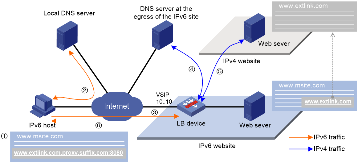
As shown in Figure 9, the working mechanism of external link proxy is as follows:
1. The IPv6 host executes the script file, and modifies the external link domain name as http://www.extlink.com.proxy.suffix.com.
2. The IPv6 host sends a DNS request to the local DNS server to query the domain name http://www.extlink.com.proxy.suffix.com. Based on the query result, the local DNS server notifies the IPv6 host of the LB device as the authoritative DNS server.
3. The IPv6 host sends a DNS request to the LB device to query the domain name http://www.extlink.com.proxy.suffix.com.
4. Upon receiving the DNS request, the LB device sends a DNS request to the DNS server to query the IPv4 address associated with the original domain name http://www.extlink.com.
5. The LB device obtains the resource associated with the external link based on the IPv4 address.
6. The LB device sends the obtained resource to the IPv6 host.
Rewriting the domain name
When the LB device detects an external link in the HTTP response from the server, it returns a script file for rewriting the external link. The client executes the script file and adds the specified parameters to the domain name of the external link. The parameters include the URI, domain name suffix, and virtual server port number. Upon receiving a DNS request containing the modified domain name, the LB device will request the associated IPv4 resource on behalf of the IPv6 client.
The format of the domain name after rewrite is protocol type://original domain name+URI+domain name suffix+:virtual server port number. The protocol type can be HTTP or HTTPS.
Suppose the protocol type is HTTP, domain name of the original external link is www.aaa.com, URI is proxy, domain name suffix is bbb.com, and virtual server port number is 8080. The external link domain name after rewrite is http://www.aaa.com.proxy.bbb.com:8080.
The device supports loading a custom script file for rewriting external links. If no custom script file is loaded, the default script file applies.
Restrictions and guidelines
Before configuring this feature, contact the server provider to configure the LB device as the authoritative DNS server on the local DNS server. This configuration enables the local DNS server to redirect DNS requests to the LB device for resolving modified domain names.
You must use the loadbalance dns-server command to specify a DNS server on the LB device to resolve original external link domain names. For more information about DNS server configuration, see "Configuring transparent DNS proxies."
If DNS packet link selection is performed by inbound link load balancing, make sure the domain name suffixes in DNS mappings are the same as those on the external link proxy.
Make sure the script file format is supported by the client browser. As a best practice, use the JS script file.
Make sure the name of the external link rewrite file is different from the response file for HTTP requests.
Procedure
1. Enter system view.
system-view
2. Enter HTTP virtual server view.
virtual-server virtual-server-name
3. Configure the URI for external link proxy.
external-link inject-uri string
By default, no URI is configured for external link proxy.
A URI is used to identify whether the domain name in a DNS request has been rewritten.
4. Configure the domain name suffix for external link proxy.
external-link inject-domain-suffix domain-suffix
By default, no domain name suffix is configured for external link proxy.
5. (Optional.) Specify the SNAT address pool for external link proxy.
external-link snat-pool pool-name
By default, no SNAT address pool is specified for external link proxy. The LB device uses the IP address of the output interface to the server as the client IP address.
Upon receiving a DNS request containing a modified domain name, the LB device extracts the original domain name and chooses an IP address from the specified SNAT pool. The LB device uses this IP address as the client IP address to initiate a request on behalf of the IPv6 client.
6. (Optional.) Add a domain name to the whitelist for external link proxy.
external-link inject-uri string
By default, no domain names are added to the whitelist for external link proxy.
The LB device does not rewrite the external links containing any domain names in the whitelist.
7. Enable external link proxy.
external-link proxy enable
By default, external link proxy is disabled.
8. Return to system view.
quit
9. (Optional.) Load an external link rewrite file.
loadbalance reload external-link file filename
By default, the default external link rewrite file is used.
If the file content has changed, you must reload the external link rewrite file to ensure it is effective.
Binding a VRRP group to a virtual server
About this task
In a VRRP hot backup system, perform this task if you configure server load balancing on the primary device in a remote backup group to make sure the return packets are processed on the same master device. For more information about remote backup groups, see hot backup configuration in High Availability Configuration Guide.
Restrictions and guidelines
Multiple virtual servers bound to different VRRP groups cannot use the same SNAT address pool.
A virtual server can be bound to a maximum of one IPv4 or IPv6 VRRP group. You can bind an IPv4 VRRP group to only an IPv4 virtual server, or bind an IPv6 VRRP group to only an IPv6 virtual server.
Procedure
1. Enter system view.
system-view
2. Enter virtual server view.
virtual-server virtual-server-name
3. Bind a VRRP group to the virtual server.
vrrp [ ipv6 ] vrid virtual-router-id interface interface-type interface-number
By default, no VRRP group is bound to a virtual server.
Configuring hot backup
About this task
To implement hot backup for two LB devices, you must enable synchronization for session extension information and sticky entries to avoid service interruption.
Restrictions and guidelines
For successful sticky entry synchronization, if you want to specify a sticky group, enable sticky entry synchronization before specifying a sticky group on both LB devices. You can specify a sticky group by using the sticky sticky-name option when you specify server farms.
In a high availability network, you must specify the global keyword for the sticky entry synchronization feature to take effect.
The following configuration changes will cause the device to delete existing sticky entries and generate new ones based on subsequent traffic:
· Disable sticky entry synchronization.
· Change the sticky entry synchronization type.
Procedure
1. Enter system view.
system-view
2. Enter virtual server view.
virtual-server virtual-server-name
3. Enable session extension information synchronization.
connection-sync enable
By default, session extension information synchronization is disabled.
The virtual servers of the HTTP type do not support this command.
4. Enable sticky entry synchronization.
sticky-sync enable [ global ]
By default, sticky entry synchronization is disabled.
Enabling IP address advertisement for a virtual server
About this task
This feature can implement load balancing among data centers in a disaster recovery network. You must enable IP address advertisement for a virtual server on the LB device in each data center.
After this feature is configured, the device advertises the IP address of the virtual server to OSPF for route calculation. When the service of a data center switches to another data center, the traffic to the virtual server can also be switched to that data center. For information about OSPF, see Layer 3—IP Routing Configuration Guide.
Restrictions and guidelines
Disable IP address advertisement for a virtual server if all the following conditions are met:
· The virtual server IP address is the same as the virtual IP address of the VRRP group associated with the virtual server.
· The virtual server IP address belongs to the same network segment as the IP address of the interface through which the device connects to the client.
You need to enable this feature when AFT collaborates with Layer 4 erver load balancing.
Procedure
1. Enter system view.
system-view
2. Enter virtual server view.
virtual-server virtual-server-name
3. Enable IP address advertisement for the virtual server.
route-advertisement enable
By default, IP address advertisement is disabled for a virtual server.
Specifying an interface for sending gratuitous ARP packets and ND packets
About this task
Perform this task to specify an interface from which gratuitous ARP packets and ND packets are sent out. For information about gratuitous ARP, see ARP configuration in Layer 3—IP Services Configuration Guide. For information about ND, see IPv6 basics configuration in Layer 3—IP Services Configuration Guide.
Restrictions and guidelines
Do not specify an interface for sending gratuitous ARP packets and ND packets if all the following conditions are met:
· The virtual server IP address is the same as the virtual IP address of the VRRP group associated with the virtual server.
· The virtual server IP address belongs to the same network segment as the IP address of the interface through which the device connects to the client.
Procedure
1. Enter system view.
system-view
2. Enter virtual server view.
virtual-server virtual-server-name
3. Specify an interface for sending gratuitous ARP packets and ND packets.
arp-nd interface interface-type interface-number
By default, no interface is specified for sending gratuitous ARP packets and ND packets.
Configuring the content to be output by using the fast log output feature
About this task
Perform this task to configure the LB-related content to be output to the log host by using the fast log output feature. For information about the fast log output feature, see Network Management and Monitoring Configuration Guide.
Prerequisites
Before performing this task, you must enable fast log output for load balancing and configure fast log output parameters.
Procedure
1. Enter system view.
system-view
2. Enter HTTP virtual server view.
virtual-server virtual-server-name
3. Configure the content to be output by using the fast log output feature.
customlog content content-value
By default, no content is output by using the fast log output feature.
Enabling a virtual server
About this task
After you configure a virtual server, you must enable the virtual server to for it to work.
Procedure
1. Enter system view.
system-view
2. Enter virtual server view.
virtual-server virtual-server-name
3. Enable the virtual server.
service enable
By default, the virtual server is disabled.
Configuring an LB class
An LB class classifies packets by comparing packets against specific rules. Matching packets are further processed by LB actions. You can create a maximum of 65535 rules for an LB class.
LB class tasks at a glance
To configure an LB class, perform the following tasks:
1. Configuring a generic LB class
b. Creating a match rule
Choose the following tasks as needed:
- Creating a match rule that references an LB class
- Creating a source IP address match rule
- Creating an interface match rule
- Creating a user group match rule
- Creating a TCP payload match rule
2. Configuring an HTTP LB class
b. Creating a match rule
Choose the following tasks as needed:
- Creating a match rule that references an LB class
- Creating a source IP address match rule
- Creating an interface match rule
- Creating a user group match rule
- Creating an HTTP content match rule
- Creating an HTTP cookie match rule
- Creating an HTTP header match rule
- Creating an HTTP URL match rule
- Creating an HTTP method match rule
- Creating an HTTP version match rule
- Creating a RADIUS attribute match rule
3. Configuring a MySQL LB class
b. Configuring a match rule
Choose the following tasks as needed:
- Creating a match rule that references an LB class
- Creating a source IP address match rule
- Creating a MySQL statement match rule
4. Configuring a RADIUS LB class
b. Creating a match rule
Choose the following tasks as needed:
- Creating a match rule that references an LB class
- Creating a source IP address match rule
- Creating a RADIUS attribute match rule
Creating an LB class
Creating an LB class for Layer 4 server load balancing
1. Enter system view.
system-view
2. Create a generic LB class, and enter LB class view.
loadbalance class class-name type generic [ match-all | match-any ]
When you create an LB class, you must specify the class type. You can enter an existing LB class view without specifying the class type. If you specify the class type when entering an existing LB class view, the class type must be the one specified when you create the LB class.
3. (Optional.) Configure a description for the LB class.
description text
By default, no description is configured for the LB class.
Creating an LB class for Layer 7 server load balancing
1. Enter system view.
system-view
2. Create an HTTP, MySQL, or RADIUS LB class, and enter LB class view.
loadbalance class class-name type { http | mysql | radius } [ match-all | match-any ]
When you create an LB class, you must specify an class type. You can enter an existing LB class view without specifying the class type. If you specify the class type when entering an existing LB class view, the class type must be the one specified when you create the LB class.
3. (Optional.) Configure a description for the LB class.
description text
By default, no description is configured for the LB class.
Creating a match rule that references an LB class
1. Enter system view.
system-view
2. Enter LB class view.
loadbalance class class-name
3. Create a match rule that references an LB class.
match [ match-id ] class class-name
Creating a source IP address match rule
1. Enter system view.
system-view
2. Enter LB class view.
loadbalance class class-name
3. Create a source IP address match rule.
match [ match-id ] source { ip address ipv4-address [ mask-length | mask ] | ipv6 address ipv6-address [ prefix-length ] }
Creating an ACL match rule
1. Enter system view.
system-view
2. Enter LB class view.
loadbalance class class-name
3. Create an ACL match rule.
match [ match-id ] acl [ ipv6 ] { acl-number | name acl-name }
Creating an interface match rule
1. Enter system view.
system-view
2. Enter generic or HTTP LB class view.
loadbalance class class-name
3. Create an interface match rule.
match [ match-id ] interface interface-type interface-number
Creating a user match rule
1. Enter system view.
system-view
2. Enter generic or HTTP LB class view.
loadbalance class class-name
3. Create a user match rule.
match [ match-id ] [ identity-domain domain-name ] user user-name
Creating a user group match rule
1. Enter system view.
system-view
2. Enter generic or HTTP LB class view.
loadbalance class class-name
3. Create a user group match rule.
match [ match-id ] [ identity-domain domain-name ] user-group user-group-name
Creating a TCP payload match rule
About this task
The device takes the corresponding LB action on TCP packets matching a TCP payload match rule. If you specify the not keyword for a TCP payload match rule, the device takes the corresponding LB action on TCP packets not matching the TCP payload match rule.
Procedure
1. Enter system view.
system-view
2. Enter generic LB class view.
loadbalance class class-name
3. Create a TCP payload match rule.
match [ match-id ] payload payload [ case-insensitive ] [ not ]
Creating an HTTP content match rule
1. Enter system view.
system-view
2. Enter HTTP LB class view.
loadbalance class class-name
3. Create an HTTP content match rule.
match [ match-id ] content content [ offset offset ]
This command is not supported by virtual servers of the fast HTTP type.
Creating an HTTP cookie match rule
1. Enter system view.
system-view
2. Enter HTTP LB class view.
loadbalance class class-name
3. Create an HTTP cookie match rule.
match [ match-id ] cookie cookie-name value value
Creating an HTTP header match rule
1. Enter system view.
system-view
2. Enter HTTP LB class view.
loadbalance class class-name
3. Create an HTTP header match rule.
match [ match-id ] header header-name value value
Creating an HTTP URL match rule
1. Enter system view.
system-view
2. Enter HTTP LB class view.
loadbalance class class-name
3. Create an HTTP URL match rule.
match [ match-id ] url url
Creating an HTTP method match rule
1. Enter system view.
system-view
2. Enter HTTP LB class view.
loadbalance class class-name
3. Create an HTTP method match rule.
match [ match-id ] method { ext ext-type | rfc rfc-type }
Creating an HTTP version match rule
1. Enter system view.
system-view
2. Enter HTTP LB class view.
loadbalance class class-name
3. Create an HTTP method match rule.
match [ match-id ] version { 1.0 | 1.1 }
Creating a MySQL statement match rule
1. Enter system view.
system-view
2. Enter MySQL LB class view.
loadbalance class class-name
3. Create a MySQL statement match rule.
match [ match-id ] sql sql [ case-insensitive ] [ not ]
Creating a RADIUS attribute match rule
1. Enter system view.
system-view
2. Enter RADIUS LB class view.
loadbalance class class-name
3. Create a RADIUS attribute match rule.
match [ match-id ] radius-attribute { code attribute-code | user-name } value attribute-value
Configuring an LB action
About LB action modes
LB actions include the following modes:
· Forwarding mode—Determines whether and how to forward packets. If no forwarding action is specified, packets are dropped.
· Modification mode—Modifies packets. To prevent the LB device from dropping the modified packets, the modification action must be used together with a forwarding action.
· Response mode—Responds to client requests by using a file.
If you create an LB action without specifying any of the previous action modes, packets are dropped.
Restrictions and guidelines
For Layer 4 server load balancing, the following configurations are mutually exclusive:
· Configure the forwarding mode.
· Specify server farms.
For Layer 7 server load balancing, any two of the following configurations are mutually exclusive:
· Specify server farms.
· Configure the redirection feature.
· Specify a response file for matching HTTP requests.
For Layer 7 server load balancing, the following configurations are also mutually exclusive:
· Match the next rule upon failure to find a real server.
· Specify a response file used upon load balancing failure.
LB action tasks at a glance
To configure an LB action, perform the following tasks:
1. Configuring a generic LB action
b. (Optional.) Configuring a forwarding LB action
- Configuring the forwarding mode
You can configure only one of the "Configuring the forwarding mode", "Specifying server farms", and "Closing TCP connections" tasks.
- (Optional.) Matching the next rule upon failure to find a real server
- (Optional.) Closing TCP connections upon failure to find a real server
c. (Optional.) Configuring a modification LB action
- Configuring the ToS field in IP packets sent to the server
2. Configuring an HTTP LB action
b. (Optional.) Configuring a forwarding LB action
You can configure only one of the "Specifying server farms" and "Closing TCP connections" tasks.
- (Optional.) Matching the next rule upon failure to find a real server
- (Optional.) Closing TCP connections upon failure to find a real server
c. (Optional.) Configuring a modification LB action
Choose the following tasks as needed:
- Configuring the ToS field in IP packets sent to the server
- Rewriting the URL in the Location header of HTTP responses from the server
- Specifying an SSL client policy
- Rewriting the content of HTTP responses
- Configuring the HTTP redirection feature
d. (Optional.) Configuring a response LB action
- Specifying a response file for matching HTTP requests
- Specifying a response file used upon load balancing failure
e. (Optional.) Enabling external link proxy
3. Configuring a RADIUS LB action
b. (Optional.) Configuring a forwarding LB action
- Matching the next rule upon failure to find a real server
c. (Optional.) Configuring a modification LB action
- Configuring the ToS field in IP packets sent to the server
Creating an LB action
Creating an LB action for Layer 4 server load balancing
1. Enter system view.
system-view
2. Create a generic LB action, and enter LB action view.
loadbalance action action-name type generic
When you create an LB action, you must specify the action type. You can enter an existing LB action view without specifying the action type. If you specify the action type when entering an existing LB action view, the action type must be the one specified when you create the LB action.
3. (Optional.) Configure a description for the LB action.
description text
By default, no description is configured for the LB action.
Creating an LB action for Layer 7 server load balancing
1. Enter system view.
system-view
2. Create an HTTP or RADIUS LB action, and enter LB action view.
loadbalance action action-name type { http | radius }
When you create an LB action, you must specify the action type. You can enter an existing LB action view without specifying the action type. If you specify the action type when entering an existing LB action view, the action type must be the one specified when you create the LB action.
3. (Optional.) Configure a description for the LB action.
description text
By default, no description is configured for the LB action.
Configuring a forwarding LB action
About this task
Three forwarding LB action types are available:
· Forward—Forwards matching packets.
· Specify server farms—When the primary server farm is available (contains available real servers), the primary server farm is used to guide packet forwarding. When the primary server farm is not available, the backup server farm is used to guide packet forwarding.
· Close TCP connections—Closes TCP connections matching the LB policy by sending FIN or RST packets.
· Match the next rule upon failure to find a real server—If the device fails to find a real server according to the LB action, it matches the packet with the next rule in the LB policy.
· Close TCP connections upon failure to find a real server—Closes TCP connections matching the LB policy by sending FIN or RST packets if the device fails to find a real server according to the LB action.
Configuring the forwarding mode
1. Enter system view.
system-view
2. Enter generic LB action view.
loadbalance action action-name
3. Configure the forwarding mode.
forward all
By default, the forwarding mode is to discard packets.
Specifying server farms
1. Enter system view.
system-view
2. Enter LB action view.
loadbalance action action-name
3. Specify server farms.
server-farm server-farm-name [ backup backup-server-farm-name ] [ sticky sticky-name [ backup backup-sticky-name ] ]
By default, no server farm is specified.
The device generates backup sticky entries for only the following sticky group combinations:
¡ RADIUS-type primary sticky group and port-address-type backup sticky group.
¡ HTTP cookie-type primary sticky group and port-address-type backup sticky group.
¡ HTTP cookie-type primary sticky group and HTTP passive-type backup sticky group.
Closing TCP connections
1. Enter system view.
system-view
2. Enter generic or HTTP LB action view.
loadbalance action action-name
3. Configure the method of closing TCP connections.
tcp-close { fin | rst }
By default, FIN packets are sent to close TCP connections.
Matching the next rule upon failure to find a real server
1. Enter system view.
system-view
2. Enter LB action view.
loadbalance action action-name
3. Match the next rule upon failure to find a real server.
fallback-action continue
By default, packets are discarded when no real servers are available for the current LB action.
Closing TCP connections upon failure to find a real server
1. Enter system view.
system-view
2. Enter generic or HTTP LB action view.
loadbalance action action-name
3. Configure the method of closing TCP connections upon failure to find a real server.
fallback-action close { fin | rst }
By default, packets are dropped when no real servers are available for the current LB action.
Configuring a modification LB action
Configuring the ToS field in IP packets sent to the server
1. Enter system view.
system-view
2. Enter LB action view.
loadbalance action action-name
3. Configure the ToS field in IP packets sent to the server.
set ip tos tos-number
By default, the ToS field in IP packets sent to the server is not changed.
Rewriting the TCP payload
1. Enter system view.
system-view
2. Enter LB action view.
loadbalance action action-name
3. Rewrite the TCP payload.
payload rewrite { both | request | response } value value replace replace-string
By default, the TCP payload is not rewritten.
Only Layer 7 TCP virtual servers can reference an LB policy that contains this action.
Handling the HTTP header
1. Enter system view.
system-view
2. Enter HTTP LB action view.
loadbalance action action-name
3. Delete an HTTP header.
header delete { both | request | response } name header-name
By default, the HTTP header is not deleted.
The device deletes the specified header from HTTP packets.
4. Insert an HTTP header.
header insert { both | request | response } name header-name value value [ encode { base64 | url } ]
By default, the HTTP header is not inserted.
The device inserts the specified header into HTTP packets.
5. Rewrite an HTTP header.
header rewrite { both | request | response } name header-name value value replace replace [ encode { base64 | url } ]
By default, the HTTP header is not rewritten.
The device rewrites the specified content of the matching header in HTTP packets as new content.
6. Rewrite the URL in HTTP requests.
header rewrite request url value value replace replace [ encode { base64 | url } ]
By default, the URL in HTTP requests is not rewritten.
Rewriting the URL in the Location header of HTTP responses from the server
1. Enter system view.
system-view
2. Enter HTTP LB action view.
loadbalance action action-name
3. Rewrite the URL in the Location header of HTTP responses from the server.
ssl url rewrite location location [ clearport clear-port ] [ sslport ssl-port ]
By default, the URL in the Location header of HTTP responses from the server is not rewritten.
If the Location header of an HTTP response packet contains the specified URL and HTTP port number, the system rewrites HTTP in the URL to HTTPS and rewrites the HTTP port number to an SSL port number.
Specifying an SSL client policy
1. Enter system view.
system-view
2. Enter HTTP LB action view.
loadbalance action action-name
3. Specify an SSL client policy for the LB action.
ssl-client-policy policy-name
By default, the LB action does not reference any SSL client policies.
Specifying an SSL client policy enables the LB device (SSL client) to send encrypted traffic to an SSL server.
You must disable and then enable a virtual server for a modified SSL policy to take effect.
Rewriting the content of HTTP responses
1. Enter system view.
system-view
2. Enter HTTP LB action view.
loadbalance action action-name
3. Rewrite the content of HTTP responses.
content rewrite value value replace replace
By default, the content of HTTP responses is not rewritten.
Configuring the HTTP redirection feature
1. Enter system view.
system-view
2. Enter HTTP LB action view.
loadbalance action action-name
3. Enable the HTTP redirection feature and specify a redirection URL for the LB action.
redirect relocation relocation
By default, the HTTP redirection feature is disabled for an LB action.
This feature redirects all HTTP request packets matching an LB action to the specified URL.
4. Specify the redirection status code that the LB device returns to a client.
redirect return-code { 301 | 302 | 307 }
By default, the redirection status code that the LB device returns to a client is 302.
This command takes effect only when the HTTP redirection feature is enabled for an LB action.
Specifying a response file for matching HTTP requests
About this task
If the URL path in a client request matches the specified URL path, the device responds to the request by using an uncompressed file.
If the URL path in a client request matches the specified working path plus a relative path in the specified zip file, the device responds to the request by using the file in the zip file.
If you configure both an uncompressed file and a compressed file for the same URL path, the uncompressed file is used to respond to matching HTTP requests.
Procedure
1. Enter system view.
system-view
2. Enter HTTP LB action view.
loadbalance action action-name
3. Specify a response file for matching HTTP requests.
response { url url file filename | workpath workpath zip-file zip-filename }
By default, no response file is specified for HTTP requests.
Specifying a response file used upon load balancing failure
About this task
This feature enables the device to respond to client requests when the device fails to find an available real server or fails to find the response file specified in the response command.
Restrictions and guidelines
The response file specified in this feature must contain a complete HTTP packet and cannot contain only the HTTP content.
Procedure
1. Enter system view.
system-view
2. Enter HTTP LB action view.
loadbalance action action-name
3. Specify a response file used upon load balancing failure.
fallback-action response raw-file raw-filename
By default, packets are discarded upon load balancing failure.
Enabling external link proxy
About this task
To perform external link proxy for a traffic class instead of all traffic of a virtual server, enable external link proxy in an HTTP LB action. Additionally, configure external link proxy parameters in the view of the virtual server (see "Configuring external link proxy") and specify the LB policy for the virtual server.
The external link proxy action does not take effect when any of the following actions is also configured:
· A forwarding LB action (except specifying server farms).
· Specifying a response file used upon load balancing failure.
Procedure
1. Enter system view.
system-view
2. Enter HTTP LB action view.
loadbalance action action-name
3. Enable external link proxy.
external-link proxy enable
By default, external link proxy is disabled.
Configuring an LB policy
About configuring an LB policy
An LB policy associates an LB class with an LB action to guide packet forwarding. In an LB policy, you can configure an LB action for packets matching the specified LB class, and configure the default action for packets matching no LB class.
You can specify multiple LB classes for an LB policy. Packets match the LB classes in the order the LB classes are configured. If an LB class is matched, the specified LB action is performed. If no LB class is matched, the default LB action is performed.
LB policy tasks at a glance
The LB policy configuration tasks for Layer 4 and Layer 7 server load balancing are the same.
To configure an LB policy, perform the following tasks:
3. Specifying the default LB action
Creating an LB policy
Creating an LB policy for Layer 4 server load balancing
1. Enter system view.
system-view
2. Create a generic LB policy, and enter LB action view.
loadbalance policy policy-name type generic
When you create an LB policy, you must specify the policy type. You can enter an existing LB policy view without specifying the policy type. If you specify the policy type when entering an existing LB policy view, the policy type must be the one specified when you create the LB policy.
3. (Optional.) Configure a description for the LB policy.
description text
By default, no description is configured for the LB policy.
Creating an LB policy for Layer 7 server load balancing
1. Enter system view.
system-view
2. Create an HTTP or RADIUS LB policy, and enter LB policy view.
loadbalance policy policy-name type { http | mysql | radius }
When you create an LB policy, you must specify the policy type. You can enter an existing LB policy view without specifying the policy type. If you specify the policy type when entering an existing LB policy view, the policy type must be the one specified when you create the LB policy.
3. (Optional.) Configure a description for the LB policy.
description text
By default, no description is configured for the LB policy.
Specifying an LB action
Restrictions and guidelines
A generic LB policy can reference only generic LB classes and generic LB actions. An HTTP LB policy can reference HTTP or generic LB classes and LB actions. A MySQL LB policy can reference MySQL or generic LB classes and generic LB actions. A RADIUS LB policy can reference RADIUS or generic LB classes and LB actions.
Procedure
1. Enter system view.
system-view
2. Enter LB policy view.
loadbalance policy policy-name
3. Specify an LB action for the specified LB class.
class class-name [ insert-before before-class-name | insert-after [ after-class-name ] ] action action-name
By default, no LB action is specified for any LB classes.
You can specify the same LB action for different LB classes.
Specifying the default LB action
Restrictions and guidelines
A generic LB policy can only reference generic LB actions. This rule does not apply to HTTP LB policies.
Procedure
1. Enter system view.
system-view
2. Enter LB policy view.
loadbalance policy policy-name
3. Specify the default LB action.
default-class action action-name
By default, no default LB action is specified.
Configuring a sticky group
A sticky group uses a sticky method to distribute similar sessions to the same real server according to sticky entries. The device assigns the first packet of a session to a real server according to the scheduling algorithm and generate a sticky entry according to the sticky method. When receiving subsequent packets of the session, the device assigns them the same real server according the sticky entry.
Sticky group tasks at a glance for Layer 4 server load balancing
2. Configuring a sticky method
Choose the following tasks as needed:
¡ Configuring the IP sticky method
¡ Configuring the UDP passive sticky method
3. (Optional.) Configuring the timeout timer for sticky entries
4. (Optional.) Ignoring the limits for sessions that match sticky entries
5. (Optional.) Enabling stickiness-over-busyness
Sticky group tasks at a glance for Layer 7 server load balancing
2. Configuring a sticky method
Choose the following tasks as needed:
¡ Configuring the IP sticky method
¡ Configuring the TCP payload sticky method
¡ Configuring the HTTP content sticky method
¡ Configuring the HTTP cookie sticky method
¡ Configuring the HTTP header sticky method
¡ Configuring HTTP passive sticky methods
¡ Configuring the HTTP or UDP payload sticky method
¡ Configuring the RADIUS attribute sticky method
¡ Configuring the SIP call ID sticky method
¡ Configuring the SSL sticky method
3. (Optional.) Configuring the timeout timer for sticky entries
4. (Optional.) Ignoring the limits for sessions that match sticky entries
5. (Optional.) Enabling stickiness-over-busyness
Creating a sticky group
Creating a sticky group for Layer 4 server load balancing
1. Enter system view.
system-view
2. Create an address- and port-type sticky group and enter sticky group view.
sticky-group group-name type address-port
When you create a sticky group, you must specify the group type. You can enter an existing sticky group view without specifying the group type. If you specify the group type when entering an existing sticky group view, the group type must be the one specified when you create the sticky group.
3. (Optional.) Configure a description for the sticky group.
description text
By default, no description is configured for the sticky group.
Creating a sticky group for Layer 7 server load balancing
1. Enter system view.
system-view
2. Create a sticky group of the HTTP content, HTTP cookie, HTTP header, HTTP/UDP payload, RADIUS, SIP, or SSL type and enter sticky group view.
sticky-group group-name type { http-content | http-cookie | http-header | http-passive | payload | radius | sip | ssl | tcp-payload | udp-passive }
When you create a sticky group, you must specify the group type. You can enter an existing sticky group view without specifying the group type. If you specify the group type when entering an existing sticky group view, the group type must be the one specified when you create the sticky group.
3. (Optional.) Configure a description for the sticky group.
description text
By default, no description is configured for the sticky group.
Configuring the IP sticky method
1. Enter system view.
system-view
2. Enter sticky group view.
sticky-group group-name
3. Configure the IP sticky method.
IPv4:
ip [ port ] { both | destination | source } [ mask mask-length ]
IPv6:
ipv6 [ port ] { both | destination | source } [ prefix prefix-length ]
By default, no IP sticky method is configured.
Configuring the TCP payload sticky method
1. Enter system view.
system-view
2. Enter sticky group view.
sticky-group group-name
3. Configure the TCP payload sticky method.
tcp-payload [ offset offset ] [ start start-string ] [ end end-string | length length ]
By default, no TCP sticky method is configured.
Configuring the UDP passive sticky method
About this task
The device obtains the payload information of an incoming UDP response based on the payload get command, and generates a sticky entry based on the obtained payload information. The device obtains the payload information of subsequent UDP requests based on the payload match command. UDP requests whose payload information matches the sticky entry are forwarded according to the sticky entry.
Restrictions and guidelines
Both the payload get and payload match commands are required for the UDP passive sticky method.
Procedure
1. Enter system view.
system-view
2. Enter sticky group view.
sticky-group group-name
3. Configure the UDP passive sticky method.
payload get [ offset offset ] [ start start-string ] [ end end-string | length length ]
payload match [ offset offset ] [ start start-string ] [ end end-string | length length ]
By default, no UDP passive sticky method is configured.
Configuring the HTTP content sticky method
1. Enter system view.
system-view
2. Enter HTTP content sticky group view.
sticky-group group-name
3. Configure the HTTP content sticky method.
content [ offset offset ] [ start start-string ] [ end end-string | length length ]
By default, no HTTP content sticky method is configured.
This command is not supported by the virtual servers of the fast HTTP type.
Configuring the HTTP cookie sticky method
1. Enter system view.
system-view
2. Enter HTTP cookie sticky group view.
sticky-group group-name
3. Configure the HTTP cookie sticky method.
cookie { get name cookie-name [ offset offset ] [ start start-string ] [ end end-string | length length ] | { insert [ domain domain-name ] [ path path ] [ httponly ] [ secure ] | rewrite } [ name cookie-name ] [ httponly ] [ secure ] }
By default, no HTTP cookie sticky method is configured.
4. (Optional.) Specify the name of the secondary cookie that appears in the URI.
cookie secondary name value
By default, the name of the secondary cookie to be searched in the URI is not specified.
5. (Optional.) Enable checking for all packets.
check all-packet
By default, the checking for all packets is disabled.
Configuring the HTTP header sticky method
1. Enter system view.
system-view
2. Enter HTTP header sticky group view.
sticky-group group-name
3. Configure the HTTP header sticky method.
header { { { host | name header-name | url } [ offset offset ] [ start start-string ] [ end end-string | length length ] } | request-method | version }
By default, no HTTP header sticky method is configured.
Configuring HTTP passive sticky methods
About this task
HTTP passive sticky methods include the HTTP header passive sticky method and the HTTP content passive sticky method.
The device obtains the header or content information of an incoming HTTP response based on the header get or content get command, and generates a sticky entry based on the obtained header or content information. The device obtains the header or content information of subsequent HTTP requests based on the header match or content match command. HTTP requests whose header or content information matches the sticky entry are forwarded according to the sticky entry.
The following rules apply to use of the match and get commands:
· A number of n strings that are obtained based on n get commands generates 2n-1 strings in ascending order of string IDs. If the string obtained based on the match command matches any one of these generated strings, the match is successful.
· A number of n strings that are obtained based on n match commands combine as one string in ascending order of string IDs.
For example, three get commands are executed with string IDs 1, 2, and 3. The device obtains three strings a, b, and c in the HTTP response header, generates seven strings a, b, c, ab, ac, bc, and abc, and generates seven sticky entries. Then, three match commands are executed with string IDs 2, 3, and 4. The device obtains three strings a, b, and c in the HTTP request header and generates one string abc. If the string matches one of the seven strings, the device generates a sticky entry based on the string abc. Subsequent HTTP requests that match the sticky entry are forwarded according to the sticky entry.
Restrictions and guidelines
Both the get and match commands are required for an HTTP passive sticky method.
You can execute a maximum of four get commands and four match commands for one HTTP passive sticky method.
Procedure
1. Enter system view.
system-view
2. Enter sticky group view.
sticky-group group-name
3. Configure the HTTP passive sticky method. Choose the options to configure as needed:
¡ Configure the HTTP header passive sticky method.
header get id name header-name start start-string { end end-string | length length }
header match id { name header-name | url } start start-string { end end-string | length length }
By default, no HTTP header passive sticky method is configured.
¡ Configure the HTTP content passive sticky method.
content get id start start-string { end end-string | length length }
content match id start start-string { end end-string | length length }
By default, no HTTP content passive sticky method is configured.
4. (Optional.) Enable checking for all packets.
check all-packet
By default, the checking for all packets is disabled.
Configuring the HTTP or UDP payload sticky method
1. Enter system view.
system-view
2. Enter HTTP or UDP payload sticky group view.
sticky-group group-name
3. Configure the HTTP or UDP payload sticky method.
payload [ offset offset ] [ start start-string ] [ end end-string | length length ]
By default, no HTTP or UDP payload sticky method is configured.
This command is not supported by the virtual servers of the fast HTTP type.
Configuring the RADIUS attribute sticky method
1. Enter system view.
system-view
2. Enter RADIUS attribute sticky group view.
sticky-group group-name
3. Configure the RADIUS attribute sticky method.
radius-attribute { code attribute-code | framed-ip-address | user-name }
By default, no RADIUS attribute sticky method is configured.
Configuring the SIP call ID sticky method
About this task
The SIP call ID sticky method allows the device to generate sticky entries based on the Call-ID header field in SIP messages. Packets with the same call ID are assigned to the same real server.
Procedure
1. Enter system view.
system-view
2. Enter SIP sticky group view.
sticky-group group-name
3. Configure the SIP call ID sticky method.
header call-id
By default, no SIP call ID sticky method is configured.
Configuring the SSL sticky method
1. Enter system view.
system-view
2. Enter SSL sticky group view.
sticky-group group-name
3. Configure the SSL sticky method based on SSL session ID.
ssl session-id
By default, no SSL sticky method is configured.
Configuring the timeout timer for sticky entries
1. Enter system view.
system-view
2. Enter sticky group view.
sticky-group group-name
3. Configure the timeout timer for sticky entries.
timeout { indefinite | timeout-value }
By default, the timeout timer for sticky entries is 86400 seconds for sticky groups of the HTTP cookie, HTTP passive, and UDP passive types and 60 seconds for sticky groups of other types.
Configuring the match scope for sticky entries
About this task
By default, the device uses sticky entries of a virtual server to match only traffic of that virtual server. You can perform this task to enlarge the match scope for sticky entries as follows:
· Match across services—If the device fails to find a matching sticky entry of the current virtual server, it continues to match the traffic against the sticky entries of other virtual servers with the same IP address but different port numbers. This match method is applicable when multiple virtual servers with the same IP address and different port numbers share the same real servers.
· Match across virtual servers—If the device fails to find a matching sticky entry of the current virtual server, it continues to match the traffic against the sticky entries of all other virtual servers. This match method is applicable when multiple virtual servers share the same real servers.
If both match methods are configured, matching across services have a higher priority. For each match scope, the most recent sticky entries are preferentially used to match traffic.
For example, three virtual servers exist and they all use the source IP sticky method. The generated sticky entries are shown in Figure 10 (only part of the entry information is displayed). Table 1 shows the different match results of different match scopes.
Figure 10 Sticky entry matching
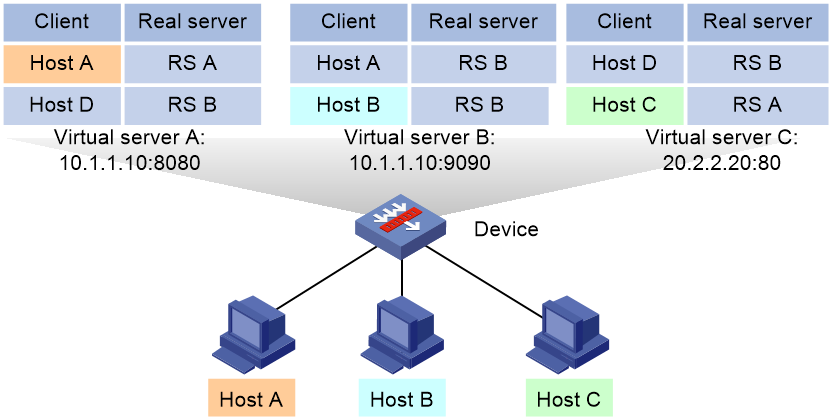
Table 1 Match result of each match scope
|
Match scope |
Match result |
|
Matching within the current virtual server |
The device matches the source IP address of requests against the sticky entry of virtual server A. · A match is found for host A, and the request from host A is distributed to real server A. · No matches are found for host B and host C, and the requests from host B and host C are distributed according the scheduling algorithm or LB policy. |
|
Matching across services |
The device matches the source IP address of requests against the sticky entry of virtual server A. · A match is found for host A, and the request from host A is distributed to real server A. · No matches are found for host B and host C, and the device continues to match the requests against the sticky entry of virtual server B. ¡ A match is found for host B, and the request from host B is distributed to real server B. ¡ No match is found for host C, and the request from host C is distributed according the scheduling algorithm or LB policy. |
|
Matching across virtual servers |
The device matches the source IP address of requests against the sticky entry of virtual server A. · A match is found for Host A, and the request from Host A is distributed to real server A. · No matches are found for host B and host C, and the device continues to match the requests against the sticky entries of virtual server B and virtual server C. ¡ A match is found for host B in virtual server B, and the request from host B is distributed to real server B. ¡ A match is found for host C in virtual server C, and the request from host C is distributed to real server A. |
Procedure
1. Enter system view.
system-view
2. Enter sticky group view.
sticky-group group-name
3. Enable cross-service matching for sticky entries.
match-across-service enable
By default, cross-service matching for sticky entries is disabled.
4. Enable cross-virtual-server matching for sticky entries.
match-across-virtual-server enable
By default, cross-virtual-server matching for sticky entries is disabled.
Ignoring the limits for sessions that match sticky entries
About this task
Perform this task to ignore the following limits for sessions that match sticky entries:
· Bandwidth and connection parameters on real servers.
· LB connection limit policies on virtual servers.
Procedure
1. Enter system view.
system-view
2. Enter sticky group view.
sticky-group group-name
3. Ignore the limits for sessions that match sticky entries.
override-limit enable
By default, the session limits apply to sessions that match sticky entries.
Enabling stickiness-over-busyness
About this task
This feature enables the device to assign client requests to real servers based on sticky entries, regardless of whether the real servers are busy.
When this feature is disabled, the device assigns client requests to only real servers in normal state.
Procedure
1. Enter system view.
system-view
2. Enter sticky group view.
sticky-group group-name
3. Enable stickiness-over-busyness.
sticky-over-busy enable
By default, stickiness-over-busyness is disabled.
Configuring a parameter profile
Parameter profile tasks at a glance
To configure a parameter profile, perform the following tasks:
1. Configuring an IP parameter profile
a. Creating a parameter profile
b. Configuring the ToS field in IP packets sent to the client
2. Configuring a TCP parameter profile
a. Creating a parameter profile
b. Configuring parameters in the profile
Choose the following tasks as needed:
- Configuring the maximum local window size for TCP connections
- Configuring the idle timeout for TCP connections
- Configuring the TIME_WAIT state timeout time for TCP connections
- Configuring the retransmission timeout time for SYN packets
- Configuring the TCP keepalive parameters
- Configuring the FIN-WAIT-1 state timeout time for TCP connections
- Configuring the FIN-WAIT-2 state timeout time for TCP connections
- Setting the MSS for the LB device
- Inserting the client IP address into the specified TCP option
- Removing the specified TCP option from TCP packet headers
- Configuring the TCP option for SNAT
3. Configuring a TCP application parameter profile
a. Creating a parameter profile
b. Configuring the TCP payload match parameters
4. Configuring an HTTP parameter profile
a. Creating a parameter profile
b. Configuring parameters in the profile
Choose the following tasks as needed:
- Enabling load balancing for each HTTP request
- Configuring connection reuse between the LB device and the server
- Modifying the header in each HTTP request or response
- Disabling case sensitivity matching for HTTP
- Configuring the maximum length to parse the HTTP content
- Configuring secondary cookie parameters
- Specifying the action to take when the header of an HTTP packet exceeds the maximum length
- Configuring the maximum size of the HTTP content
- Configuring the cookie encryption feature
5. Configuring an HTTP-compression parameter profile
a. Creating a parameter profile
b. Configuring the HTTP compression feature
6. Configuring an HTTP-statistics parameter profile
a. Creating a parameter profile
b. Configuring the HTTP statistics feature
7. Configuring a MySQL parameter profile
a. Creating a parameter profile
b. Configuring connection reuse between the LB device and the server
Creating a parameter profile
Creating a parameter profile for Layer 4 server load balancing
1. Enter system view.
system-view
2. Create an IP parameter profile and enter parameter profile view.
parameter-profile profile-name type ip
When you create a parameter profile, you must specify the profile type. You can enter an existing parameter profile view without specifying the profile type. If you specify the profile type when entering an existing parameter profile view, the profile type must be the one specified when you create the parameter profile.
3. (Optional.) Configure a description for the parameter profile.
description text
By default, no description is configured for the parameter profile.
Creating a parameter profile for Layer 7 server load balancing
1. Enter system view.
system-view
2. Create a parameter profile of the HTTP, HTTP-compression, HTTP-statistics, MySQL, OneConnect, TCP, or TCP-application type and enter parameter profile view.
parameter-profile profile-name type { http | http-compression | http-statistics | mysql | oneconnect | tcp | tcp-application }
When you create a parameter profile, you must specify the profile type. You can enter an existing parameter profile view without specifying the profile type. If you specify the profile type when entering an existing parameter profile view, the profile type must be the one specified when you create the parameter profile.
3. (Optional.) Configure a description for the parameter profile.
description text
By default, no description is configured for the parameter profile.
Configuring the ToS field in IP packets sent to the client
1. Enter system view.
system-view
2. Enter IP parameter profile view.
parameter-profile profile-name
3. Configure the ToS field in the IP packets sent to the client.
set ip tos tos-number
By default, the ToS field in IP packets sent to the client is not changed.
Configuring the maximum local window size for TCP connections
1. Enter system view.
system-view
2. Enter TCP parameter profile view.
parameter-profile profile-name
3. Configure the maximum local window size for TCP connections.
tcp window-size size
By default, the maximum local window size is 65535 for TCP connections.
Configuring the idle timeout for TCP connections
About this task
Perform this task to configure the idle timeout for TCP connections between the LB device and the clients and for TCP connections between the LB device and the servers. If no traffic is available on a TCP connection before the idle timeout expires, the LB device terminates the TCP connection.
Procedure
1. Enter system view.
system-view
2. Enter TCP parameter profile view.
parameter-profile profile-name
3. Configure the idle timeout for TCP connections.
tcp connection idle-timeout value
By default, the idle timeout is 0 seconds, which means TCP connections never time out.
Configuring the TIME_WAIT state timeout time for TCP connections
About this task
The TCP TIME_WAIT timer is twice the Maximum Segment Lifetime (MSL), which is the maximum amount of time that any segment can exist on the network before being dropped.
A TCP connection cannot be released until the TIME_WAIT timer expires. To release TCP connections faster and improve load balancing efficiency, perform this task to set a smaller TIME_WAIT state timeout time.
Procedure
1. Enter system view.
system-view
2. Enter TCP parameter profile view.
parameter-profile profile-name
3. Configure the TIME_WAIT state timeout time.
time-wait timeout value
By default, the TIME_WAIT state timeout time for TCP connections is 2 seconds.
Configuring the retransmission timeout time for SYN packets
1. Enter system view.
system-view
2. Enter TCP parameter profile view.
parameter-profile profile-name
3. Configure the retransmission timeout time for SYN packets.
syn retransmission-timeout timeout-value
By default, the retransmission timeout time for SYN packets is 10 seconds.
Configuring the TCP keepalive parameters
1. Enter system view.
system-view
2. Enter TCP parameter profile view.
parameter-profile profile-name
3. Configure the idle timeout time for sending keepalive packets.
keepalive idle-timeout timeout-value
By default, the idle timeout time for sending keepalive packets is 1800 seconds.
4. Configure the retransmission interval and retransmission times for keepalive packets.
keepalive retransmission interval interval count count
By default, the retransmission interval is 10 seconds, and the retransmission times is 3.
Configuring the FIN-WAIT-1 state timeout time for TCP connections
1. Enter system view.
system-view
2. Enter TCP parameter profile view.
parameter-profile profile-name
3. Configure the FIN-WAIT-1 state timeout time.
fin-wait1 timeout timeout-value
By default, the FIN-WAIT-1 state timeout time for TCP connections is 5 seconds.
Configuring the FIN-WAIT-2 state timeout time for TCP connections
1. Enter system view.
system-view
2. Enter TCP parameter profile view.
parameter-profile profile-name
3. Configure the FIN-WAIT-2 state timeout time.
fin-wait2 timeout timeout-value
By default, the FIN-WAIT-2 state timeout time for TCP connections is 5 seconds.
Specifying the action to take on the segments that exceed the MSS in the HTTP requests from the client
1. Enter system view.
system-view
2. Enter TCP parameter profile view.
parameter-profile profile-name
3. Specify the action to take on the segments that exceed the MSS in the HTTP requests from the client.
exceed-mss { allow | drop }
By default, the device allows the segments to exceed the MSS in the HTTP requests from the client.
Setting the MSS for the LB device
About this task
When a client establishes a TCP connection to the LB device, the client sends its own MSS (maximum segment size) value to the LB device. The LB device records the MSS value and sends the configured MSS value to the client. The client and the LB device use the smaller MSS value for communication.
When the LB device establishes a TCP connection to the server, the LB device sends the configured MSS value to the server. The server records the MSS value and sends its own MSS value to the LB device. The LB device and the server use the smaller MSS value for communication.
Procedure
1. Enter system view.
system-view
2. Enter TCP parameter profile view.
parameter-profile profile-name
3. Set the MSS for the LB device.
tcp mss value
By default, the MSS is not set for the LB device.
Inserting the client IP address into the specified TCP option
About this task
This feature enables the LB device to insert the client's actual IP address into the specified option in headers of TCP packets sent to the server.
Restrictions and guidelines
This feature takes effect only on TCP parameter profiles referenced by the following virtual servers:
· HTTP virtual servers.
· TCP virtual servers configured with SSL server policies.
· TCP virtual servers operating at Layer 7.
· MySQL virtual servers.
Procedure
1. Enter system view.
system-view
2. Enter TCP parameter profile view.
parameter-profile profile-name
3. Insert the client IP address into a TCP option.
tcp option insert option-number src-addr [ encode { binary | string } ]
By default, the client IP address is not inserted into any TCP options.
Removing the specified TCP option from TCP packet headers
About this task
This feature enables the LB device to remove the specified TCP option from headers of TCP packets sent to the server.
Procedure
1. Enter system view.
system-view
2. Enter TCP parameter profile view.
parameter-profile profile-name
3. Remove the specified TCP option from TCP packet headers.
tcp option remove option-number
By default, no TCP option is removed from TCP packet headers.
Configuring the TCP option for SNAT
About this task
This feature enables the LB device to translate the source IP address of packets into the IP address in the specified TCP option. To use this feature, you must configure the TCP option translation mode for SNAT (see "Configuring NAT").
Procedure
1. Enter system view.
system-view
2. Enter TCP parameter profile view.
parameter-profile profile-name
3. Configure the TCP option for SNAT.
src-addr-option option-number [ encode { binary | string } ]
By default, no TCP option is configured for SNAT.
This command takes effect only in a client-side parameter profile specified for a virtual server.
Configuring the TCP payload match parameters
About this task
For the TCP payload match rule, the device buffers traffic for TCP payload matching during the buffering period. The device stops buffering traffic when any of the following events occurs:
· The device receives the buffering end string.
· The size of buffered data exceeds the specified buffering size.
· The buffered data matches the TCP payload match rule.
Procedure
1. Enter system view.
system-view
2. Enter TCP-application parameter profile view.
parameter-profile profile-name
3. Set the buffering period for TCP payload matching.
match-buffer-time time
By default, the buffering period for TCP payload matching is 3 seconds.
4. Configure a condition for ending data buffering in TCP payload matching. Choose the options to configure as needed:
¡ Set the maximum buffering size.
match-buffer-size size
By default, the maximum buffering size is 4096 bytes.
¡ Configure the buffering end string.
match-buffer-end string
By default, no buffering end string is configured.
Enabling load balancing for each HTTP request
1. Enter system view.
system-view
2. Enter HTTP parameter profile view.
parameter-profile profile-name
3. Enable load balancing for each HTTP request.
rebalance per-request
By default, load balancing applies to the first HTTP request of a connection. Other HTTP requests are processed in the same way the first request is processed.
Configuring connection reuse between the LB device and the server
About this task
This feature allows the LB device to establish connections to the server that can be reused by multiple clients.
After you enable connection reuse, you can configure the following parameters:
· Idle timeout time—Amount of time that a TCP connection can stay idle before it is disconnected. After the TCP connection is disconnected, new connection requests trigger establishment of new TCP connections.
· Maximum reuse times—Maximum number of times that a TCP connection can be reused. The TCP connection is not disconnected until the maximum number of reuse times is reached. After the TCP connection is disconnected, new connection requests trigger establishment of a new TCP connection.
· IPv4 mask/IPv6 prefix—Limits the network segment of clients that can reuse connections between the LB device and servers. If the client that initiates a connection request is in the same network segment as the idle TCP connection, the idle TCP connection is reused. If the client does not match this requirement, a new TCP connection is established.
· MySQL connection pool—After MySQL data transfer is completed, the TCP connection is stored in a connection pool instead of being closed. For a new connection request, the device selects an available connection from the connection pool before attempting to open a new connection. When the number of connections in the pool reaches the maximum, idle connections are no longer stored in the pool.
Enabling connection reuse between the LB device and the server
1. Enter system view.
system-view
2. Enter HTTP or MySQL parameter profile view.
parameter-profile profile-name
3. Enable connection reuse between the LB device and the server.
server-connection reuse
By default, connection reuse is disabled between the LB device and the server.
This command is not supported by the virtual servers of the fast HTTP type.
4. Return to system view.
quit
Configuring connection reuse parameters
1. Enter MySQL or OneConnect parameter profile view
parameter-profile profile-name
2. (Optional.) Set the idle timeout time for TCP connections between the LB device and servers.
idle-time idle-time
The default setting is 86400 seconds.
3. (Optional.) Set the maximum number of times that a TCP connection can be reused.
max-reuse reuse-number
The default setting is 1000.
4. (Optional.) Specify the IPv4 mask for connection reuse.
ip source mask { mask-length | mask }
By default, the IPv4 mask for connection reuse is the natural mask.
5. (Optional.) Specify the IPv6 prefix length for connection reuse.
ipv6 source prefix prefix-length
By default, client IPv6 addresses with a prefix length of 0 can reuse connections.
6. (Optional.) Set the maximum number of connections allowed in the MySQL connection pool.
pool-size pool-size
The default setting is 1024.
This command is supported only in MySQL parameter profiles.
Modifying the header in each HTTP request or response
1. Enter system view.
system-view
2. Enter HTTP parameter profile view.
parameter-profile profile-name
3. Perform the insert, delete, or modify operation for the header in each HTTP request or response.
header modify per-request
By default, the insert, delete, or modify operation is performed for the header in the first HTTP request or response of a connection.
Disabling case sensitivity matching for HTTP
1. Enter system view.
system-view
2. Enter HTTP parameter profile view.
parameter-profile profile-name
3. Disable case sensitivity matching for HTTP.
case-insensitive
By default, case sensitivity matching is enabled for HTTP.
Configuring the maximum length to parse the HTTP content
1. Enter system view.
system-view
2. Enter HTTP parameter profile view.
parameter-profile profile-name
3. Configure the maximum length to parse the HTTP content.
content maxparse-length length
By default, the maximum length to parse the HTTP content is 4096.
This command is not supported by the virtual servers of the fast HTTP type.
4. Configure the maximum length to parse HTTP headers.
header maxparse-length length
By default, the maximum length to parse HTTP headers is 4096.
This command is not supported by the virtual servers of the fast HTTP type.
Configuring secondary cookie parameters
1. Enter system view.
system-view
2. Enter HTTP parameter profile view.
parameter-profile profile-name
3. Configure the delimiter that separates secondary cookies in a URL.
secondary-cookie delimiters text
By default, the delimiter that separates secondary cookies in a URL is slash (/), ampersand (&), number sign (#), or plus (+).
4. Configure the start string for secondary cookies in a URL.
secondary-cookie start text
By default, the start string for secondary cookies in a URL is question mark (?).
Specifying the action to take when the header of an HTTP packet exceeds the maximum length
1. Enter system view.
system-view
2. Enter HTTP parameter profile view.
parameter-profile profile-name
3. Specify the action to take when the header of an HTTP packet exceeds the maximum length.
header exceed-length { continue | drop }
By default, the system continues to perform load balancing for HTTP requests or responses when their packet headers exceed the maximum length.
This command is not supported by the virtual servers of the fast HTTP type.
Configuring the maximum size of the HTTP content
About this task
If the size of the HTTP content in an HTTP request exceeds the specified maximum size, the device discards the HTTP request.
Procedure
1. Enter system view.
system-view
2. Enter HTTP parameter profile view.
parameter-profile profile-name
3. Configuring the maximum size of the HTTP content.
content request-max-length length
By default, the size of the HTTP content is not limited.
Configuring the cookie encryption feature
About this task
This feature allows the device to encrypt the Set-Cookie field in HTTP responses to prevent personal information from being revealed. When a client request contains an encrypted cookie, the device decrypts the cookie before sending the request to the server.
Procedure
1. Enter system view.
system-view
2. Enter HTTP parameter profile view.
parameter-profile profile-name
3. Configure cookie encryption.
encrypt-cookie name cookie-name key { cipher | simple } string
By default, no cookie is encrypted.
Virtual servers of the fast HTTP type do not support this command.
Configuring the HTTP compression feature
1. Enter system view.
system-view
2. Enter HTTP-compression parameter profile view.
parameter-profile profile-name
3. Set the minimum length of HTTP response content for compression.
content length-threshold length
By default, the minimum length of HTTP response content for compression is 1024 bytes.
4. Set the compression level.
compression level level
By default, the compression level is 1.
5. Set the memory size used for compression.
memory-size size
By default, the memory size used for compression is 8 KB.
6. Enable compression for responses to HTTP 1.0 requests.
request-version all
By default, compression is disabled for responses to HTTP 1.0 requests.
7. Specify the preferred compression algorithm.
prefer-method { deflate | gzip }
By default, the preferred compression algorithm is gzip.
8. Delete the Accept-Encoding header from HTTP requests.
header delete request accept-encoding
By default, the Accept-Encoding header is deleted from HTTP requests.
9. Insert the Vary header to HTTP responses and set the header content to Accept-Encoding.
header insert response vary
By default, the Vary header is inserted to HTTP responses, and the header content is Accept-Encoding.
10. Configure a filtering rule for compression.
rule [ rule-id ] { permit | deny } { content-type | url } expression
By default, no filtering rules are configured.
11. Set the window size used for compression.
window-size size
By default, the window size used for compression is 16 KB.
Configuring the HTTP statistics feature
About this task
This feature allows you to collect statistics about HTTP traffic destined for matching URLs by configuring an HTTP-statistics parameter profile.
If HTTP packets match the specified URL and source IP address object group, they are counted based on the source IP address object group. If HTTP packets match the specified URL but do not match the specified source IP address object group, they are counted based on the source IP address.
You can configure multiple URL match rules for one statistics node to count the total amount of traffic destined for these URLs.
Procedure
1. Enter system view.
system-view
2. Enter HTTP-statistics parameter profile view.
parameter-profile profile-name
3. (Optional.) Enable collection of HTTP traffic statistics by source IP address object group.
source-ip object-group object-group-name
By default, HTTP traffic statistics are collected on a per-IP address basis.
4. Create a statistics node and enter its view.
node node-name
5. Configure a URL match rule.
statistics-match [ rule-id ] url url
By default, a statistics node does not have URL match rules.
6. (Optional.) Configure a description for the statistics node.
description text
By default, no description is configured for a statistics node.
Configuring a protection policy
About configuring a protection policy
A protection policy can prevent the LB device and servers from being overwhelmed by a large number of forged requests.
You can specify protection rules in a protection policy and specify a protection action to take on the traffic matching the protection rules.
Protection policy tasks at a glance
To configure a protection policy, perform the following tasks:
1. Creating a protection policy
2. Configuring a protection rule
3. Configuring a protection action
Creating a protection policy
1. Enter system view.
system-view
2. Create an HTTP protection policy and enter protection policy view.
loadbalance protection-policy policy-name [ type http ]
When you create a protection policy, you must specify the policy type. You can enter the view of an existing protection policy without specifying the policy type.
3. (Optional.) Configure a description for the protection policy.
description text
By default, no description is configured for a protection policy.
Configuring a protection rule
About this task
A protection rule defines the URLs to be protected and the protection period. A protection action is taken if the number of times a user accesses a protected URL exceeds the configured protection threshold. The device determines whether requests belong to the same user based on the following elements:
· Source IP address—Requests with the same source IP address belong to the same user.
· Cookie—Requests with the same cookie value for the specified cookie belong to the same user.
You can configure multiple protection rules in a protection policy. The device compares the URL in a packet with the URLs configured in the protection rules according to the order of the rule IDs. If a match is found and the configured protection threshold is exceeded, the device performs the associated protection action. If the URL in the packet does not match the URL configured in a specific protection rule, the device compares the URL with the next protection rule.
Restrictions and guidelines
Configure an appropriate protection period. Setting the protection period too long might allow attack packets to pass through. Setting the protection period too short might generate frequent, unnecessary reports.
Procedure
1. Enter system view.
system-view
2. Enter HTTP protection policy view.
loadbalance protection-policy policy-name
3. Create a protection rule and enter protection rule view.
rule rule-id
4. Configure the URLs to be protected.
protected-url url
By default, no URLs are protected.
5. Configure a protection threshold. Choose the options to configure as needed:
¡ Configure a source-IP-based request threshold.
source-ip request-threshold threshold
¡ Configure a cookie-based request threshold.
cookie cookie-name request-threshold threshold
By default, no protection threshold is configured.
If you configure both options, the protection action is taken when either threshold is exceeded.
6. Configure a protection threshold.
protection-period period
The default setting is 120 seconds.
Configuring a protection action
About this task
The device supports the following protection actions:
· Warning—Generates a log message and sends it to the information center.
· Drop—Drops requests.
· Verify cookie—Returns a response carrying a cookie value to the client. If a subsequent request carries the returned cookie value, it passes the verification. If a subsequent request does not carry a cookie value or carries a different cookie value, it fails to pass the verification and is dropped. The device supports returning a cookie value by inserting an HTTP header or a JS script.
Procedure
1. Enter system view.
system-view
2. Enter HTTP protection policy view.
loadbalance protection-policy policy-name
3. Configure a protection action.
protection-action { warning | { drop | verify { insert-header | js } } } *
By default, no protection action is configured.
Configuring an LB probe template
About configuring an LB probe template
You can configure a TCP RST, TCP zero-window, or HTTP passive, or custom-monitoring LB probe template.
By using a TCP RST, TCP zero-window, or HTTP passive LB probe template, the device counts the number of RST packets or zero-window packets sent by each server farm member in a server farm or the number of URL errors in HTTP responses. The device identifies the health of server farm members according to the packet count or the number of URL errors in HTTP responses. It takes one of the following protection actions when the packet count threshold or URL error count threshold is reached:
· Places a real server in busy state—After placing a real server in busy state, the device starts probing the real server at the specified probe intervals. If the number of RST or zero-window packets sent does not reach the threshold in a probe interval, the real server is placed back in normal state. If threshold violation persists when the maximum probe times is reached, the system automatically shuts down the real server.
· Shuts down a real server—Automatically shuts down the real server and sets the server state to Auto shutdown.
By using a custom-monitoring LB probe template, the device monitors the state of real servers through the user-defined script file during the monitoring time.
Restrictions and guidelines
The protection action for an HTTP passive LB probe template can only be shut down real servers (auto shutdown) and is not configurable.
In a hot backup network, upload the script file for custom monitoring through the Web interface.
Configuring a TCP-RST LB probe template
1. Enter system view.
system-view
2. Create a TCP-RST LB probe template and enter its view.
loadbalance probe-template tcp-rst template-name
3. (Optional.) Configure a description for the TCP-RST LB probe template.
description text
By default, no description is configured for a TCP-RST LB probe template.
4. Set the monitoring time for the TCP-RST LB probe template.
monitor-interval interval-time
By default, the monitoring time is 10 seconds.
5. Set the RST packet count threshold for the TCP-RST LB probe template.
rst threshold number
By default, the RST packet count threshold is 1000000.
6. Configure the protection action for the TCP-RST LB probe template.
protect-action { auto-shutdown | busy [ probe-interval interval ] [ probe-times times ] }
By default, the protection action is to place a real server in busy state.
Configuring a TCP zero-window LB probe template
1. Enter system view.
system-view
2. Create a TCP zero-window LB probe template and enter its view.
loadbalance probe-template tcp-zero-window template-name
3. (Optional.) Configure a description for the TCP zero-window LB probe template.
description text
By default, no description is configured for a TCP zero-window LB probe template.
4. Set the monitoring time for the TCP zero-window LB probe template.
monitor-interval interval-time
By default, the monitoring time is 10 seconds.
5. Set the percentage threshold of zero-window packets for the TCP zero-window LB probe template.
zero-window threshold percentage
By default, the percentage threshold of zero-window packets is 40%.
6. Configure the protection action for the TCP zero-window LB probe template.
protect-action { auto-shutdown | busy [ probe-interval interval ] [ probe-times times ] }
By default, the protection action is to place a real server in busy state.
Configuring an HTTP passive LB probe template
1. Enter system view.
system-view
2. Create an HTTP passive LB probe template and enter its view.
loadbalance probe-template http-passive template-name
3. (Optional.) Configure a description for the HTTP passive LB probe template.
description text
By default, no description is configured for an HTTP passive LB probe template.
4. Set the monitoring time for the HTTP passive LB probe template.
monitor-interval interval-time
By default, the monitoring time is 1 second.
5. Set the upper limit of URL error times for the HTTP passive LB probe template.
abnormal-url threshold number
By default, the upper limit of URL error times is 10000.
6. Configure a URL regular expression to match URLs.
check-url url
By default, no URL regular expression is configured.
A maximum of 10 URL regular expressions can be configured for an HTTP passive probe template.
7. Configure a response status code to check.
status-code code
By default, no response status code is configured for checking.
A maximum of 10 response status codes can be configured for an HTTP passive probe template.
8. Set the timeout time for waiting for responses.
timeout timeout
The default setting is 5 seconds.
Configuring a custom-monitoring LB probe template
1. Enter system view.
system-view
2. Create a custom-monitoring LB probe template and enter its view.
loadbalance probe-template external-monitor template-name
3. (Optional.) Configure a description for the custom-monitoring LB probe template.
description text
By default, no description is configured for a custom-monitoring LB probe template.
4. Set the monitoring time for the custom-monitoring LB probe template.
monitor-interval interval-time
The default setting is 5 seconds.
5. Specify a script file to be used for the custom-monitoring LB probe template.
external-script file-name
By default, no script file is specified.
6. Configure an environment variable for custom monitoring.
env-variables variable-name value variable-value
By default, no environment variables are configured for custom monitoring.
7. Configure user-defined information.
argument text
By default, no user-defined information is configured.
8. Set the timeout time for waiting for responses.
timeout timeout
The default setting is 3 seconds.
9. Return to system view.
quit
10. Set the maximum number of processes that can be started for custom monitoring.
loadbalance process-limit number
By default, only one process can be started for custom monitoring.
Configuring a SNAT global policy
About configuring a SNAT global policy
Perform this task to translate the source IP addresses of packets into the specified IP addresses.
Restrictions and guidelines
You can configure a SNAT global policy in system view and configure SNAT in server farm view. The SNAT configuration in server farm view has higher priority. A server farm without SNAT configuration uses the SNAT global policy for address translation.
NAT global policy tasks at a glance
To configure a SNAT global policy, perform the following tasks:
1. Creating a
2. Configure a translation mode for the
3. (Optional.) Setting the priority of the SNAT global policy
4. (Optional.) Configuring filtering criteria for SNAT
¡ Specifying a source IP address object group for address translation
¡ Specifying a destination IP address object group for address translation
¡ Specifying a service object group for address translation
5. (Optional.) Specifying a VPN instance for the SNAT global policy
6. Enabling the SNAT global policy
Creating a SNAT global policy
1. Enter system view.
system-view
2. Create a SNAT global policy and enter its view.
loadbalance snat-global-policy policy-name
3. (Optional.) Configure a description for the SNAT global policy.
description text
By default, no description is configured for a SNAT global policy.
Configure a translation mode for the SNAT global policy
About this task
The device supports the following translation methods in a SNAT global policy:
· Automatic mapping—Translates the source IP address into the IP address of the interface connecting to the real server.
· SNAT address pool—Translates the source IP address into an IP address in the specified SNAT address pool.
Procedure
1. Enter system view.
system-view
2. Enter SNAT global policy view.
loadbalance snat-global-policy policy-name
3. Configure a translation mode for the SNAT global policy.
translation-mode { auto-map | snat-pool pool-name }
By default, no translation mode is configured for a SNAT global policy.
Setting the priority of the SNAT global policy
About this task
You can configure multiple SNAT global policies with different priorities. They are matched in descending order of priority values.
Procedure
1. Enter system view.
system-view
2. Enter SNAT global policy view.
loadbalance snat-global-policy policy-name
3. Set the priority of the SNAT global policy.
priority priority
The default setting is 0.
Specifying a source IP address object group for address translation
About this task
If you specify a source IP address object group, the device performs SNAT on only packets with a matching source IP address. For information about configuring an IP address object group, see object group configuration in Security Configuration Guide.
Procedure
1. Enter system view.
system-view
2. Enter SNAT global policy view.
loadbalance snat-global-policy policy-name
3. Specify a source IP address object group for address translation.
source-ip object-group object-group-name
By default, all packets are translated.
Specifying a destination IP address object group for address translation
About this task
If you specify a destination IP address object group, the device performs SNAT on only packets with a matching destination IP address. For information about configuring an IP address object group, see object group configuration in Security Configuration Guide.
Procedure
1. Enter system view.
system-view
2. Enter SNAT global policy view.
loadbalance snat-global-policy policy-name
3. Specify a destination IP address object group for address translation.
destination-ip object-group object-group-name
By default, all packets are translated.
Specifying a service object group for address translation
About this task
If you specify a service object group, the device performs SNAT on only packets with a matching service. For information about configuring a service object group, see object group configuration in Security Configuration Guide.
Procedure
1. Enter system view.
system-view
2. Enter SNAT global policy view.
loadbalance snat-global-policy policy-name
3. Specify a service object group for address translation.
service object-group object-group-name
By default, all packets are translated.
Specifying a VPN instance for the SNAT global policy
1. Enter system view.
system-view
2. Enter SNAT global policy view.
loadbalance snat-global-policy policy-name
3. Specify a VPN instance for the SNAT global policy.
vpn-instance vpn-instance-name
By default, a SNAT global policy belongs to the public network.
Enabling the SNAT global policy
1. Enter system view.
system-view
2. Enter SNAT global policy view.
loadbalance snat-global-policy policy-name
3. Enable the SNAT global policy.
snat enable
By default, a SNAT global policy is disabled.
Configuring an LB connection limit policy
About this task
Using an LB connection limit policy can limit the number of connections on the device. It helps prevent a large number of connections from consuming too many device system resources and server resources. In this way, internal network resources (hosts or servers) are protected, and device system resources can be used more appropriately.
An LB connection limit policy can have multiple rules. Each rule specifies a range of users and the limit to the user connections. A connection limit policy applies only to the user connections matching a rule. When the number of connections for a certain type reaches the upper limit (max-amount), the device does not accept new connection requests of that type. It accepts new connection requests only when the number of connections drops below the lower limit (min-amount).
The user ranges in the rules are set by using ACLs.
Procedure
1. Enter system view.
system-view
2. Create an LB connection limit policy, and enter LB connection limit policy view.
loadbalance limit-policy policy-name
3. Configure an LB connection limit rule.
limit limit-id acl [ ipv6 ] { acl-number | name acl-name } [ per-destination | per-service | per-source ] * amount max-amount min-amount
By default, an LB connection limit policy does not contain rules.
4. (Optional.) Configure a description for the LB connection limit policy.
description text
By default, no description is configured for an LB connection limit policy.
Configuring the ALG feature
About this task
The Application Level Gateway (ALG) feature distributes parent and child sessions to the same link.
Restrictions and guidelines
SIP fragmentation packets do not support ALG.
Procedure
1. Enter system view.
system-view
2. Enable ALG.
¡ Enable
ALG for the specified protocol:
loadbalance
alg { dns | ftp | h323 | icmp-error | ils | mgcp | nbt | pptp | rsh | rtsp | sccp | sip | sqlnet | tftp | xdmcp }
¡ Enable ALG for all protocols:
loadbalance
alg all-enable
By default, ALG is enabled for the DNS, FTP, PPTP, and RTSP protocols and ICMP error packets.
Reloading a response file
About this task
If a response file (specified in the response or fallback-action response raw-file command) changes, you must reload the file to make it take effect.
Procedure
1. Enter system view.
system-view
2. Reload a response file.
reload http-response { file filename }
Performing a load balancing test
About performing a load balancing test
Perform this task in any view to test the load balancing result.
Performing an IPv4 load balancing test
To perform an IPv4 load balancing test, execute the following command in any view:
loadbalance schedule-test ip [ vpn-instance vpn-instance-name ] { application http { message-file file-name | method { get | post } url url [ header header ]&<1-10> [ content content-value ] } | protocol { protocol-number | icmp | tcp | udp } } destination destination-address destination-port destination-port source source-address source-port source-port [ slot slot-number ]
Performing an IPv6 load balancing test
To perform an IPv6 load balancing test, execute the following command in any view:
loadbalance schedule-test ipv6 [ vpn-instance vpn-instance-name ] { application http { message-file file-name | method { get | post } url url [ header header ]&<1-10> [ content content-value ] } | protocol { protocol-number | icmpv6 | tcp | udp } } destination destination-address destination-port destination-port source source-address source-port source-port [ slot slot-number ]
Enabling SNMP notifications
About this task
To report critical load balancing events to an NMS, enable SNMP notifications for load balancing. For load balancing event notifications to be sent correctly, you must also configure SNMP as described in Network Management and Monitoring Configuration Guide.
The SNMP notifications configuration tasks for Layer 4 and Layer 7 server load balancing are the same.
Procedure
1. Enter system view.
system-view
2. Enable SNMP notifications for load balancing.
snmp-agent trap enable loadbalance
By default, SNMP notifications are enabled for load balancing.
Enabling load balancing logging
About load balancing logging
For security auditing purposes, enable load balancing logging to record load balancing information. Load balancing logging includes basic logging and NAT logging.
Load balancing basic logging generates logs for the following events:
· The state of a real server or real server group changes.
· The health monitoring result of a real server changes.
· The number of connections on a real server or virtual server reaches or drops below the upper limit.
· The connection establishment rate on a real server or virtual server reaches or drops below the upper limit.
· A primary/backup server farm switchover occurs between server farms specified for a virtual server.
· A primary/backup server farm switchover occurs between server farms specified for an LB action.
Load balancing NAT logging records NAT session information, including IP address and port translation information and access information.
Enabling load balancing basic logging
1. Enter system view.
system-view
2. Enable load balancing basic logging.
loadbalance log enable base
By default, load balancing basic logging is enabled.
Enabling load balancing NAT logging
1. Enter system view.
system-view
2. Enable load balancing NAT logging.
loadbalance log enable nat
By default, load balancing NAT logging is disabled.
Displaying and maintaining server load balancing
Execute display commands in any view and reset commands in user view.
|
Task |
Command |
|
Display LB action information. |
display loadbalance action [ name action-name ] |
|
Display LB class information. |
display loadbalance class [ name class-name ] |
|
Display Layer 7 LB TCP connection information. |
display loadbalance connections [ client-side{ ipv4 | ipv6 } [ cs-client-ip ip-address [ cs-client-port port-number ] ] [ cs-server-ip ip-address [ cs-server-port port-number ] ] [ state { closed | close_wait | closing | established | fin_wait_1 | fin_wait_2 | last_ack | listening | syn_received | syn_sent | time_wait } ] ] [ server-side { ipv4 | ipv6 } [ ss-client-ip ip-address [ ss-client-port port-number ] ] [ ss-server-ip ip-address [ ss-server-port port-number ] ] [ state { closed | close_wait | closing | established | fin_wait_1 | fin_wait_2 | last_ack | listening | syn_received | syn_sent | time_wait } ] ] [ slot slot-number ] [ verbose ] |
|
Display information about the domain names queried by external link proxy. |
display loadbalance dns-query [ vpn-instance vpn-instance-name ] display loadbalance dns-query [ vpn-instance vpn-instance-name ] [ slot slot-number ] |
|
Display LB hot backup statistics. |
display loadbalance hot-backup statistics [ slot slot-number ] |
|
Display LB connection limit policy information. |
display loadbalance limit-policy [ name policy-name ] |
|
Display LB policy information. |
display loadbalance policy [ name policy-name ] |
|
Display the maximum number of processes that can be started for custom monitoring. |
display loadbalance process-limit |
|
Display LB probe template information. |
display loadbalance probe-template [ name template-name ] |
|
Display the configuration of protection policies. |
display loadbalance protection-policy [ name policy-name ] |
|
Display SNAT global policy information. |
display loadbalance snat-global-policy [ name policy-name ] |
|
Display SNAT address pool information. |
display loadbalance snat-pool [ name pool-name ] |
|
Display cumulative statistics for all virtual servers. |
display loadbalance virtual-server total-statistics [ slot slot-number ] |
|
Display parameter profile information. |
display parameter-profile [ name parameter-name ] |
|
Display real server information. |
display real-server [ brief | name real-server-name ] |
|
Display server farm member information. |
display real-server server-farm server-farm-name [ name real-server-name port port-number ] |
|
Display real server statistics. |
display real-server statistics [ name real-server-name ] [ slot slot-number ] |
|
Display server farm member statistics. |
display real-server statistics server-farm server-farm-name [ name real-server-name port port-number ] [ slot slot-number ] |
|
Display server farm information. |
display server-farm [ brief | name server-farm-name ] |
|
Display sticky entry information for virutal servers. |
display sticky statistics [ dns-proxy | virtual-server ] display sticky statistics [ dns-proxy | virtual-server ] [ slot slot-number ] |
|
Display sticky statistics. |
display sticky virtual-server [ virtual-server-name virtual-server-name ] [ [ link { ip ipv4-address | ipv6 ipv6-address | interface { interface-type interface-number | interface-name } } | link-group link-group-name ] * | [ real-server-addr { ipv4-address | ipv6-address } | real-server-port port-number | server-farm server-farm-name | text text ] * ] [ class { class-name | default-class } | client-addr { ipv4-address | ipv6-address } | sticky-type { address-port | http-content | http-cookie | http-header | http-passive | payload | radius | sip | ssl | tcp-payload | udp-passive } [ key sticky-key ] ] * [ brief ] display sticky virtual-server [ virtual-server-name virtual-server-name ] [ [ link { ip ipv4-address | ipv6 ipv6-address | interface { interface-type interface-number | interface-name } } | link-group link-group-name ] * | [ real-server-addr { ipv4-address | ipv6-address } | real-server-port port-number | server-farm server-farm-name | text text ] * ] [ class { class-name | default-class } | client-addr { ipv4-address | ipv6-address } | sticky-type { address-port | http-content | http-cookie | http-header | http-passive | payload | radius | sip | ssl | tcp-payload | udp-passive } [ key sticky-key ] ] * [ brief ] [ slot slot-number ] |
|
Display sticky group information. |
display sticky-group [ name group-name ] |
|
Display virtual server information. |
display virtual-server [ brief | name virtual-server-name ] |
|
Display virtual server statistics. |
display virtual-server statistics [ name virtual-server-name ] [ slot slot-number ] |
|
Display the ALG status for all protocols. |
display loadbalance alg |
|
Perform a PCRE regular expression match test and display the match result. |
loadbalance test pcre value value { string string | file file-name } [ offset offset ] [ case-insensitive ] |
|
Perform a regular-expression-based rewrite test and display the rewrite result. |
loadbalance test rewrite value value replace replace-string { string string | file file-name } [ offset offset ] [ case-insensitive ] |
|
Clear LB hot backup statistics. |
|
|
Clear real server statistics. |
reset real-server statistics [ real-server-name ] |
|
Clear server farm member statistics. |
reset real-server statistics server-farm server-farm-name [ name real-server-name port port-number ] |
|
Clear sticky entry information for virutal servers. |
reset sticky virtual-server [ virtual-server-name virtual-server-name ] [ [ link { ip ipv4-address | ipv6 ipv6-address | interface { interface-type interface-number | interface-name } } | link-group link-group-name ] * | [ real-server-addr { ipv4-address | ipv6-address } | real-server-port port-number | server-farm server-farm-name | text text ] * ] [ class { class-name | default-class } | client-addr { ipv4-address | ipv6-address } | sticky-type { address-port | http-content | http-cookie | http-header | http-passive | payload | radius | sip | ssl | tcp-payload | udp-passive } [ key sticky-key ] ] * reset sticky virtual-server [ virtual-server-name virtual-server-name ] [ [ link { ip ipv4-address | ipv6 ipv6-address | interface { interface-type interface-number | interface-name } } | link-group link-group-name ] * | [ real-server-addr { ipv4-address | ipv6-address } | real-server-port port-number | server-farm server-farm-name | text text ] * ] [ class { class-name | default-class } | client-addr { ipv4-address | ipv6-address } | sticky-type { address-port | http-content | http-cookie | http-header | http-passive | payload | radius | sip | ssl | tcp-payload | udp-passive } [ key sticky-key ] ] * [ slot slot-number ] |
|
Clear virtual server statistics. |
reset virtual-server statistics [ virtual-server-name ] |
Server load balancing configuration examples
Example: Configuring basic Layer 4 server load balancing
Network configuration
In Figure 11, physical servers Server A, Server B, and Server C provide FTP services, and are in descending order of hardware configuration.
Configure server load balancing on the device to distribute user requests among the servers based on their hardware performance, and use health monitoring to monitor the reachability of the servers.
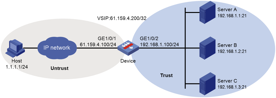
Procedure
1. Configure the device:
¡ Assign IP addresses to interfaces:
# Assign an IP address to interface GigabitEthernet 1/0/1.
<Device> system-view
[Device] interface gigabitethernet 1/0/1
[Device-GigabitEthernet1/0/1] ip address 61.159.4.100 255.255.255.0
[Device-GigabitEthernet1/0/1] quit
# Assign IP addresses to other interfaces in the same way. (Details not shown.)
¡ Configure settings for routing.
This example configures a static route, and the next hop in the route is 61.159.4.1.
[Device] ip route-static 1.1.1.1 24 61.159.4.1
¡ Add interfaces to security zones.
[Device] security-zone name untrust
[Device-security-zone-Untrust] import interface gigabitethernet 1/0/1
[Device-security-zone-Untrust] quit
[Device] security-zone name trust
[Device-security-zone-Trust] import interface gigabitethernet 1/0/2
[Device-security-zone-Trust] quit
¡ Configure a security policy:
Configure rules to permit traffic from the Untrust security zone to the Trust security zone and traffic from the Local security zone to the Trust security zone, so the users can access the servers:
# Configure a rule named lbrule1 to allow the users to access the servers.
[Device] security-policy ip
[Device-security-policy-ip] rule name lbrule1
[Device-security-policy-ip-1-lbrule1] source-zone untrust
[Device-security-policy-ip-1-lbrule1] destination-zone trust
[Device-security-policy-ip-1-lbrule1] destination-ip-subnet 192.168.1.0 255.255.255.0
[Device-security-policy-ip-1-lbrule1] action pass
[Device-security-policy-ip-1-lbrule1] quit
# Configure a rule named lblocalout to allow the device to send probe packets to the servers.
[Device-security-policy-ip] rule name lblocalout
[Device-security-policy-ip-2-lblocalout] source-zone local
[Device-security-policy-ip-2-lblocalout] destination-zone trust
[Device-security-policy-ip-2-lblocalout] destination-ip-subnet 192.168.1.0 255.255.255.0
[Device-security-policy-ip-2-lblocalout] action pass
[Device-security-policy-ip-2-lblocalout] quit
[Device-security-policy-ip] quit
¡ Configure a server farm.
# Create the ICMP-type NQA template t1.
[Device] nqa template icmp t1
[Device-nqatplt-icmp-t1] quit
# Create the server farm sf, and specify the scheduling algorithm as weighted round robin and health monitoring method as t1.
[Device] server-farm sf
[Device-sfarm-sf] predictor round-robin
[Device-sfarm-sf] probe t1
[Device-sfarm-sf] quit
¡ Configure real servers.
# Create the real server rs1 with IPv4 address 192.168.1.1, port number 21, and weight 150, and add it to the server farm sf.
[Device] real-server rs1
[Device-rserver-rs1] ip address 192.168.1.1
[Device-rserver-rs1] port 21
[Device-rserver-rs1] weight 150
[Device-rserver-rs1] server-farm sf
[Device-rserver-rs1] quit
# Create the real server rs2 with IPv4 address 192.168.1.2, port number 21, and weight 120, and add it to the server farm sf.
[Device] real-server rs2
[Device-rserver-rs2] ip address 192.168.1.2
[Device-rserver-rs2] port 21
[Device-rserver-rs2] weight 120
[Device-rserver-rs2] server-farm sf
[Device-rserver-rs2] quit
# Create the real server rs3 with IPv4 address 192.168.1.3, port number 21, and weight 80, and add it to the server farm sf.
[Device] real-server rs3
[Device-rserver-rs3] ip address 192.168.1.3
[Device-rserver-rs3] port 21
[Device-rserver-rs3] weight 80
[Device-rserver-rs3] server-farm sf
[Device-rserver-rs3] quit
¡ Configure a virtual server.
# Create the TCP virtual server vs with VSIP 61.159.4.200, specify its default master server farm sf, and enable the virtual server.
[Device] virtual-server vs type tcp
[Device-vs-tcp-vs] virtual ip address 61.159.4.200
[Device-vs-tcp-vs] default server-farm sf
[Device-vs-tcp-vs] service enable
# Specify an interface for sending gratuitous ARP packets and ND packets (if the interface IP address on the device and the VSIP belong to the same subnet).
[Device-vs-tcp-vs] arp-nd interface GigabitEthernet 1/0/1
[Device-vs-tcp-vs] quit
2. Configure the physical servers:
# Specify the default gateway 192.168.1.100 for physical servers Server A, Server B, and Server C. (Details not shown.)
Verifying the configuration
# Display brief information about all real servers.
[Device] display real-server brief
Real server Address Port State VPN instance Server farm
rs1 192.168.1.1 21 Active sf
rs2 192.168.1.2 21 Active sf
rs3 192.168.1.3 21 Active sf
# Display detailed information about all server farms.
[Device] display server-farm
Server farm: sf
Description:
Predictor: Round robin
Proximity: Disabled
NAT: Enabled
SNAT pool:
Failed action: Keep
Active threshold: Disabled
Slow-online: Disabled
Selected server: Disabled
Probe information:
Probe success criteria: All
Probe method:
t1
Total real server: 3
Active real server: 3
Real server list:
Name State VPN instance Address Port Weight Priority
rs1 Active 192.168.1.1 21 150 4
rs2 Active 192.168.1.2 21 120 4
rs3 Active 192.168.1.3 21 80 4
# Display detailed information about all virtual servers.
[Device] display virtual-server
Virtual server: vs
Description:
Type: TCP
State: Active
VPN instance:
Virtual IPv4 address: 61.159.4.200/32
Virtual IPv6 address: --
Port: 0
Primary server farm: sf (in use)
Backup server farm:
Sticky:
LB policy:
Connection limit: --
Rate limit:
Connections: --
Bandwidth: --
Inbound bandwidth: --
Outbound bandwidth: --
Connection synchronization: Disabled
Sticky synchronization: Disabled
Bandwidth busy protection: Disabled
Interface bandwidth statistics: Disabled
Route advertisement: Disabled
Example: Configuring Layer 4 server load balancing hot backup
Network configuration
In Figure 12, physical servers Server A, Server B, and Server C provide FTP services, and are in descending order of hardware configuration.
Configure server load balancing on the devices to distribute user requests among the servers based on their hardware performance, and use health monitoring to monitor reachability of the servers.
For high availability purposes, implement hot backup for the devices. To ensure traffic continuity, enable synchronization for session extension information and sticky entries on the devices.
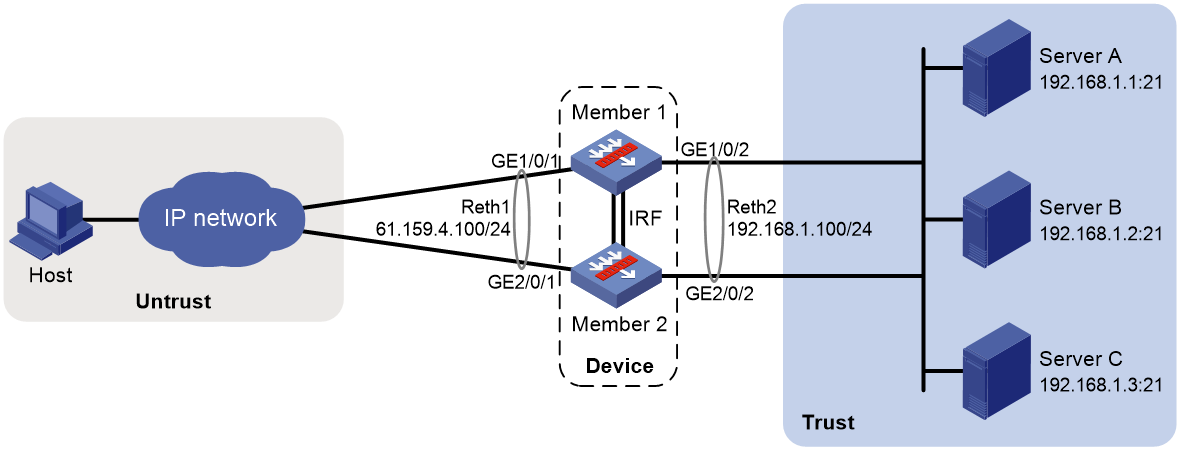
Procedure
1. Configure the devices:
¡ Assign IP addresses to interfaces and configure routes, security zones, zone pairs, and interzone policies. Make sure the network connections are available. (Details not shown.)
¡ Configure IRF.
# Set up an IRF fabric for the two LB devices with member IDs 1 and 2. (Details not shown.)
For more information about IRF, see Virtual Technologies Configuration Guide.
¡ Configure Reth interfaces.
# Create Reth 1, and assign an IP address to Reth 1. Assign member interfaces to Reth 1, and set their priorities.
[Device] interface reth 1
[Device-Reth1] ip address 61.159.4.100 24
[Device-Reth1] member interface gigabitethernet 1/0/1 priority 20
[Device-Reth1] member interface gigabitethernet 2/0/1 priority 10
[Device-Reth1] quit
# Create Reth 2, and assign an IP address to Reth 1. Assign member interfaces to Reth 2, and set their priorities.
[Device] interface reth 2
[Device-Reth2] ip address 192.168.1.100 24
[Device-Reth2] member interface gigabitethernet 1/0/2 priority 20
[Device-Reth2] member interface gigabitethernet 2/0/2 priority 10
[Device-Reth2] quit
¡ Configure a redundancy group.
# Create track entries to monitor the link state of the Ethernet interfaces.
[Device] track 1 interface gigabitethernet 1/0/1
[Device] track 2 interface gigabitethernet 1/0/2
[Device] track 3 interface gigabitethernet 2/0/1
[Device] track 4 interface gigabitethernet 2/0/2
# Create the redundancy group bkp and assign Reth 1 and Reth 2 to the redundancy group.
[Device] redundancy group bkp
[Device-redundancy-group-bkp] member interface reth 1
[Device-redundancy-group-bkp] member interface reth 2
# Create node 1 (with priority 100) for the redundancy group bkp and bind node 1 to IRF member device 1. Associate track entries 1 and 2 with node 1.
[Device-redundancy-group-bkp] node 1
[Device-redundancy-group-bkp-node-1] priority 100
[Device-redundancy-group-bkp-node-1] bind slot 1
[Device-redundancy-group-bkp-node-1] track 1 interface gigabitethernet 1/0/1
[Device-redundancy-group-bkp-node-1] track 2 interface gigabitethernet 1/0/2
[Device-redundancy-group-bkp-node-1] quit
# Create node 2 (with priority 50) for the redundancy group bkp and bind node 2 to IRF member device 2. Associate track entries 3 and 4 with node 2.
[Device-redundancy-group-bkp] node 2
[Device-redundancy-group-bkp-node2] priority 50
[Device-redundancy-group-bkp-node2] bind slot 2
[Device-redundancy-group-bkp-node2] track 3 interface gigabitethernet 2/0/1
[Device-redundancy-group-bkp-node2] track 4 interface gigabitethernet 2/0/2
[Device-redundancy-group-bkp-node2] quit
[Device-redundancy-group-bkp] quit
¡ Enable session synchronization for stateful failover.
[Device] session synchronization enable
¡ Configure a server farm.
# Create the ICMP-type NQA template t1.
[Device] nqa template icmp t1
[Device-nqatplt-icmp-t1] quit
# Create the server farm sf, and specify the scheduling algorithm as weighted round robin and health monitoring method as t1.
[Device] server-farm sf
[Device-sfarm-sf] predictor round-robin
[Device-sfarm-sf] probe t1
[Device-sfarm-sf] quit
¡ Configure real servers.
# Create the real server rs1 with IPv4 address 192.168.1.1, port number 21, and weight 150, and add it to the server farm sf.
[Device] real-server rs1
[Device-rserver-rs1] ip address 192.168.1.1
[Device-rserver-rs1] port 21
[Device-rserver-rs1] weight 150
[Device-rserver-rs1] server-farm sf
[Device-rserver-rs1] quit
# Create the real server rs2 with IPv4 address 192.168.1.2, port number 21, and weight 120, and add it to the server farm sf.
[Device] real-server rs2
[Device-rserver-rs2] ip address 192.168.1.2
[Device-rserver-rs2] port 21
[Device-rserver-rs2] weight 120
[Device-rserver-rs2] server-farm sf
[Device-rserver-rs2] quit
# Create the real server rs3 with IPv4 address 192.168.1.3, port number 21, and weight 80, and add it to the server farm sf.
[Device] real-server rs3
[Device-rserver-rs3] ip address 192.168.1.3
[Device-rserver-rs3] port 21
[Device-rserver-rs3] weight 80
[Device-rserver-rs3] server-farm sf
[Device-rserver-rs3] quit
¡ Configure a virtual server.
# Create the TCP virtual server vs with VSIP 61.159.4.200, and specify its default master server farm sf. Enable synchronization for session extension information and sticky entries, and enable the virtual server.
[Device] virtual-server vs type tcp
[Device-vs-tcp-vs] virtual ip address 61.159.4.200
[Device-vs-tcp-vs] default server-farm sf
[Device-vs-tcp-vs] connection-sync enable
[Device-vs-tcp-vs] sticky-sync enable
[Device-vs-tcp-vs] service enable
[Device-vs-tcp-vs] quit
2. Configure the physical servers:
# Specify the default gateway 192.168.1.100 for physical servers Server A, Server B, and Server C. (Details not shown.)
Verifying the configuration
# Display information about the redundancy group bkp.
[Device] display redundancy group bkp
Redundancy group bkp (ID 1):
Node ID Slot Priority Status Track weight
1 Slot1 100 Primary 255
2 Slot2 50 Secondary 255
Preempt delay time remained : 0 min
Preempt delay timer setting : 1 min
Remaining hold-down time : 0 sec
Hold-down timer setting : 1 sec
Manual switchover request : No
Member interfaces:
Reth1 Reth2
Member failover groups:
Node 1:
Track info:
Track Status Reduced weight Interface
1 Positive 255 GE1/0/1
2 Positive 255 GE1/0/2
Node 2:
Track info:
Track Status Reduced weight Interface
3 Negative 255 GE2/0/1
4 Negative 255 GE2/0/2
# Display brief information about all real servers.
[Device] display real-server brief
Real server Address Port State VPN instance Server farm
rs1 192.168.1.1 21 Active sf
rs2 192.168.1.2 21 Active sf
rs3 192.168.1.3 21 Active sf
# Display detailed information about all server farms.
[Device] display server-farm
Server farm: sf
Description:
Predictor: Round robin
Proximity: Disabled
NAT: Enabled
SNAT pool:
Failed action: Keep
Active threshold: Disabled
Slow-online: Disabled
Selected server: Disabled
Probe information:
Probe success criteria: All
Probe method:
t1
Total real server: 3
Active real server: 3
Real server list:
Name State VPN instance Address Port Weight Priority
rs1 Active 192.168.1.1 21 150 4
rs2 Active 192.168.1.2 21 120 4
rs3 Active 192.168.1.3 21 80 4
# Display detailed information about all virtual servers.
[Device] display virtual-server
Virtual server: vs
Description:
Type: TCP
State: Active
VPN instance:
Virtual IPv4 address: 61.159.4.200/32
Virtual IPv6 address: --
Port: 0
Primary server farm: sf (in use)
Backup server farm:
Sticky:
LB policy:
Connection limit: --
Rate limit:
Connections: --
Bandwidth: --
Inbound bandwidth: --
Outbound bandwidth: --
Connection synchronization: Enabled
Sticky synchronization: Enabled
Bandwidth busy protection: Disabled
Interface bandwidth statistics: Disabled
Route advertisement: Disabled
Example: Configuring basic Layer 7 server load balancing
Network configuration
In Figure 13, physical servers Server A, Server B, and Server C provide HTTP services, and are in descending order of hardware configuration.
Configure server load balancing on the device to distribute user requests among the servers based on their hardware performance, and use health monitoring to monitor reachability of the servers.
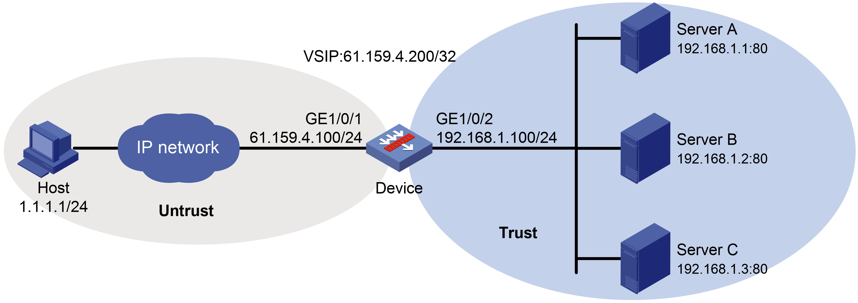
Procedure
1. Configure the device:
¡ Assign IP addresses to interfaces:
# Assign an IP address to interface GigabitEthernet 1/0/1.
<Device> system-view
[Device] interface gigabitethernet 1/0/1
[Device-GigabitEthernet1/0/1] ip address 61.159.4.100 255.255.255.0
[Device-GigabitEthernet1/0/1] quit
# Assign IP addresses to other interfaces in the same way. (Details not shown.)
¡ Configure settings for routing.
This example configures a static route, and the next hop in the route is 61.159.4.1.
[Device] ip route-static 1.1.1.1 24 61.159.4.1
¡ Add interfaces to security zones.
[Device] security-zone name untrust
[Device-security-zone-Untrust] import interface gigabitethernet 1/0/1
[Device-security-zone-Untrust] quit
[Device] security-zone name trust
[Device-security-zone-Trust] import interface gigabitethernet 1/0/2
[Device-security-zone-Trust] quit
¡ Configure a security policy:
Configure rules to permit traffic from the Untrust security zone to the Local security zone and traffic from the Local security zone to the Trust security zone, so the users can access the servers:
# Configure a rule named lblocalin to allow the users to send packets to the device.
[Device] security-policy ip
[Device-security-policy-ip] rule name lblocalin
[Device-security-policy-ip-1-lblocalin] source-zone untrust
[Device-security-policy-ip-1-lblocalin] destination-zone local
[Device-security-policy-ip-1-lblocalin] destination-ip-subnet 61.159.4.0 255.255.255.0
[Device-security-policy-ip-1-lblocalin] action pass
[Device-security-policy-ip-1-lblocalin] quit
# Configure a rule named lblocalout to allow the device to send packets to the servers.
[Device-security-policy-ip] rule name lblocalout
[Device-security-policy-ip-2-lblocalout] source-zone local
[Device-security-policy-ip-2-lblocalout] destination-zone trust
[Device-security-policy-ip-2-lblocalout] destination-ip-subnet 192.168.1.0 255.255.255.0
[Device-security-policy-ip-2-lblocalout] action pass
[Device-security-policy-ip-2-lblocalout] quit
[Device-security-policy-ip] quit
¡ Configure a server farm.
# Create the HTTP-type NQA template t1.
[Device] nqa template http t1
[Device-nqatplt-http-t1] quit
# Create server farm sf, and specify the scheduling algorithm as weighted round robin and health monitoring method as t1.
[Device] server-farm sf
[Device-sfarm-sf] predictor round-robin
[Device-sfarm-sf] probe t1
[Device-sfarm-sf] quit
¡ Configure real servers.
# Create the real server rs1 with IPv4 address 192.168.1.1, port number 8080, and weight 150, and add it to the server farm sf.
[Device] real-server rs1
[Device-rserver-rs1] ip address 192.168.1.1
[Device-rserver-rs1] port 8080
[Device-rserver-rs1] weight 150
[Device-rserver-rs1] server-farm sf
[Device-rserver-rs1] quit
# Create the real server rs2 with IPv4 address 192.168.1.2, port number 8080, and weight 120, and add it to the server farm sf.
[Device] real-server rs2
[Device-rserver-rs2] ip address 192.168.1.2
[Device-rserver-rs2] port 8080
[Device-rserver-rs2] weight 120
[Device-rserver-rs2] server-farm sf
[Device-rserver-rs2] quit
# Create the real server rs3 with IPv4 address 192.168.1.3, port number 8080, and weight 80, and add it to the server farm sf.
[Device] real-server rs3
[Device-rserver-rs3] ip address 192.168.1.3
[Device-rserver-rs3] port 8080
[Device-rserver-rs3] weight 80
[Device-rserver-rs3] server-farm sf
[Device-rserver-rs3] quit
¡ Configure a virtual server.
# Create the HTTP virtual server vs with VSIP 61.159.4.200, specify its default master server farm sf, and enable the virtual server.
[Device] virtual-server vs type http
[Device-vs-http-vs] virtual ip address 61.159.4.200
[Device-vs-http-vs] default server-farm sf
[Device-vs-http-vs] service enable
# Specify an interface for sending gratuitous ARP packets and ND packets (if the interface IP address on the device and the VSIP belong to the same subnet).
[Device-vs-tcp-vs] arp-nd interface GigabitEthernet 1/0/1
[Device-vs-http-vs] quit
2. Configure the physical servers:
# Specify the default gateway 192.168.1.100 for physical servers Server A, Server B, and Server C. (Details not shown.)
Verifying the configuration
# Display brief information about all real servers.
[Device] display real-server brief
Real server Address Port State VPN instance Server farm
rs1 192.168.1.1 8080 Active sf
rs2 192.168.1.2 8080 Active sf
rs3 192.168.1.3 8080 Active sf
# Display detailed information about all server farms.
[Device] display server-farm
Server farm: sf
Description:
Predictor: Round robin
Proximity: Disabled
NAT: Enabled
SNAT pool:
Failed action: Keep
Active threshold: Disabled
Slow-online: Disabled
Selected server: Disabled
Probe information:
Probe success criteria: All
Probe method:
t1
Total real server: 3
Active real server: 3
Real server list:
Name State VPN instance Address Port Weight Priority
rs1 Active 192.168.1.1 8080 150 4
rs2 Active 192.168.1.2 8080 120 4
rs3 Active 192.168.1.3 8080 80 4
# Display detailed information about all virtual servers.
[Device] display virtual-server
Virtual server: vs
Description:
Type: HTTP
State: Active
VPN instance:
Virtual IPv4 address: 61.159.4.200/32
Virtual IPv6 address: --
Port: 80
Primary server farm: sf (in use)
Backup server farm:
Sticky:
LB policy:
HTTP parameter profile:
Connection limit: --
Rate limit:
Connections: --
Bandwidth: --
Inbound bandwidth: --
Outbound bandwidth: --
SSL server policy:
SSL client policy:
Redirect relocation:
Redirect return-code: 302
Sticky synchronization: Disabled
Bandwidth busy protection: Disabled
Interface bandwidth statistics: Disabled
Route advertisement: Disabled
Example: Configuring Layer 7 server load balancing SSL termination
Network configuration
In Figure 14, physical servers Server A, Server B, and Server C provide HTTP services, and are in descending order of hardware configuration.
Configure server load balancing on the device to distribute user requests among the servers based on their hardware performance, and use health monitoring to monitor reachability of the servers.
The device establishes an HTTPS connection encrypted by SSL with the host, and establishes HTTP connections with the servers. The device must terminate the SSL session with the host before establishing a TCP connection with a server.

Procedure
1. Configure the device:
¡ Assign IP addresses to interfaces:
# Assign an IP address to interface GigabitEthernet 1/0/1.
<Device> system-view
[Device] interface gigabitethernet 1/0/1
[Device-GigabitEthernet1/0/1] ip address 61.159.4.100 255.255.255.0
[Device-GigabitEthernet1/0/1] quit
# Assign IP addresses to other interfaces in the same way. (Details not shown.)
¡ Configure settings for routing.
This example configures a static route, and the next hop in the route is 61.159.4.1.
[Device] ip route-static 1.1.1.1 24 61.159.4.1
¡ Add interfaces to security zones.
[Device] security-zone name untrust
[Device-security-zone-Untrust] import interface gigabitethernet 1/0/1
[Device-security-zone-Untrust] quit
[Device] security-zone name trust
[Device-security-zone-Trust] import interface gigabitethernet 1/0/2
[Device-security-zone-Trust] quit
¡ Configure a security policy:
Configure rules to permit traffic from the Untrust security zone to the Local security zone and traffic from the Local security zone to the Trust security zone, so the users can access the servers:
# Configure a rule named lblocalin to allow the users to send packets to the device.
[Device] security-policy ip
[Device-security-policy-ip] rule name lblocalin
[Device-security-policy-ip-1-lblocalin] source-zone untrust
[Device-security-policy-ip-1-lblocalin] destination-zone local
[Device-security-policy-ip-1-lblocalin] destination-ip-subnet 61.159.4.0 255.255.255.0
[Device-security-policy-ip-1-lblocalin] action pass
[Device-security-policy-ip-1-lblocalin] quit
# Configure a rule named lblocalout to allow the device to send packets to the servers.
[Device-security-policy-ip] rule name lblocalout
[Device-security-policy-ip-2-lblocalout] source-zone local
[Device-security-policy-ip-2-lblocalout] destination-zone trust
[Device-security-policy-ip-2-lblocalout] destination-ip-subnet 192.168.1.0 255.255.255.0
[Device-security-policy-ip-2-lblocalout] action pass
[Device-security-policy-ip-2-lblocalout] quit
[Device-security-policy-ip] quit
¡ Configure a server farm.
# Create the SSL-type NQA template t1.
[Device] nqa template ssl t1
[Device-nqatplt-ssl-t1] quit
# Create the server farm sf, and specify the scheduling algorithm as weighted round robin and health monitoring method as t1.
[Device] server-farm sf
[Device-sfarm-sf] predictor round-robin
[Device-sfarm-sf] probe t1
[Device-sfarm-sf] quit
¡ Configure an SSL server policy:
# Configure PKI domain 1. (For more information about configuring a PKI domain, see Security Configuration Guide.)
[Device] pki domain 1
# Create an SSL server policy named ssp.
[Device] ssl server-policy ssp
# Specify PKI domain 1 for SSL server policy ssp.
[Device-ssl-server-policy-ssp] pki-domain 1
# Enable client authentication.
[Device-ssl-server-policy-ssp] client-verify enable
[Device-ssl-server-policy-ssp] quit
# Apply SSL server policy ssp to control HTTPS access.
[Device] ip https ssl-server-policy ssp
# Enable the HTTPS service.
[Device] ip https enable
# Create a local user named usera, set the password to 123456TESTplat&! in plaintext form, specify the service type as HTTPS, and specify the user role for the local user as network-admin.
[Device] local-user usera
[Device-luser-usera] password simple 123456TESTplat&!
[Device-luser-usera] service-type https
[Device-luser-usera] authorization-attribute user-role network-admin
¡ Configure real servers.
# Create the real server rs1 with IPv4 address 192.168.1.1, port number 8080, and weight 150, and add it to the server farm sf.
[Device] real-server rs1
[Device-rserver-rs1] ip address 192.168.1.1
[Device-rserver-rs1] port 8080
[Device-rserver-rs1] weight 150
[Device-rserver-rs1] server-farm sf
[Device-rserver-rs1] quit
# Create the real server rs2 with IPv4 address 192.168.1.2, port number 8080, and weight 120, and add it to the server farm sf.
[Device] real-server rs2
[Device-rserver-rs2] ip address 192.168.1.2
[Device-rserver-rs2] port 8080
[Device-rserver-rs2] weight 120
[Device-rserver-rs2] server-farm sf
[Device-rserver-rs2] quit
# Create the real server rs3 with IPv4 address 192.168.1.3, port number 8080, and weight 80, and add it to the server farm sf.
[Device] real-server rs3
[Device-rserver-rs3] ip address 192.168.1.3
[Device-rserver-rs3] port 8080
[Device-rserver-rs3] weight 80
[Device-rserver-rs3] server-farm sf
[Device-rserver-rs3] quit
¡ Configure a virtual server.
# Create the HTTP virtual server vs with VSIP 61.159.4.200 and port number 443, and specify its default master server farm sf.
[Device] virtual-server vs type http
[Device-vs-http-vs] virtual ip address 61.159.4.200
[Device-vs-http-vs] port 443
[Device-vs-http-vs] default server-farm sf
# Specify the SSL server policy ssp for the virtual server.
[Device-vs-http-vs] ssl-server-policy ssp
# Enable the virtual server.
[Device-vs-http-vs] service enable
# Specify an interface for sending gratuitous ARP packets and ND packets (if the interface IP address on the device and the VSIP belong to the same subnet).
[Device-vs-tcp-vs] arp-nd interface GigabitEthernet 1/0/1
[Device-vs-http-vs] quit
2. Configure the physical servers:
# Specify the default gateway 192.168.1.100 for physical servers Server A, Server B, and Server C. (Details not shown.)
Verifying the configuration
# Display brief information about all real servers.
[Device] display real-server brief
Real server Address Port State VPN instance Server farm
rs1 192.168.1.1 8080 Active sf
rs2 192.168.1.2 8080 Active sf
rs3 192.168.1.3 8080 Active sf
# Display detailed information about all server farms.
[Device] display server-farm
Server farm: sf
Description:
Predictor: Round robin
Proximity: Disabled
NAT: Enabled
SNAT pool:
Failed action: Keep
Active threshold: Disabled
Slow-online: Disabled
Selected server: Disabled
Total real server: 3
Active real server: 3
Real server list:
Name State VPN instance Address Port Weight Priority
rs1 Active 192.168.1.1 8080 150 4
rs2 Active 192.168.1.2 8080 120 4
rs3 Active 192.168.1.3 8080 80 4
# Display detailed information about all virtual servers.
[Device] display virtual-server
Virtual server: vs
Description:
Type: HTTP
State: Active
VPN instance:
Virtual IPv4 address: 61.159.4.200/32
Virtual IPv6 address: --
Port: 443
Default server farm: sf (in use)
Backup server farm:
Sticky:
LB policy:
HTTP parameter profile:
Connection limit: --
Rate limit:
Connections: --
Bandwidth: --
Inbound bandwidth: --
Outbound bandwidth: --
SSL server policy: ssp
SSL client policy:
Redirect relocation:
Redirect return-code: 302
Connection synchronization: Disabled
Sticky synchronization: Disabled
Bandwidth busy protection: Disabled
Interface bandwidth statistics: Disabled
Route advertisement: Disabled
Configuring outbound link load balancing
About outbound link load balancing
Outbound link load balancing load balances traffic among the links from the internal network to the external network.
Typical network diagram
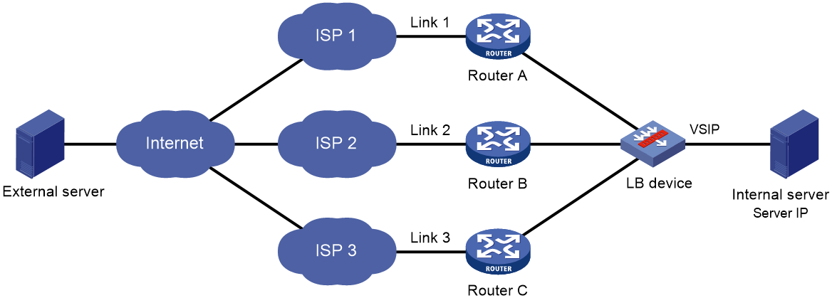
As shown in Figure 15, outbound link load balancing contains the following elements:
· LB device—Distributes outbound traffic among multiple links.
· Link—Physical links provided by ISPs.
· VSIP—Virtual service IP address of the cluster, which identifies the destination network for packets from the internal network.
· Server IP—IP address of a server.
Workflow
Figure 16 shows the outbound link load balancing workflow.
Figure 16 Outbound link load balancing workflow

The workflow for outbound link load balancing is as follows:
1. The LB device receives traffic from the internal server.
2. The LB device selects the optimal link based on the LB policy, sticky method, proximity algorithm, and scheduling algorithm (typically the bandwidth algorithm or maximum bandwidth algorithm) in turn.
3. The LB device forwards the traffic to the external server through the optimal link.
4. The LB device receives traffic from the external server.
5. The LB device forwards the traffic to the internal server.
Outbound link load balancing tasks at a glance
Relationship between configuration items
Figure 17 shows the relationship between the following configuration items:
· Link group—A collection of links that contain similar functions. A link group can be referenced by a virtual server or an LB action.
· Link—Physical links provided by ISPs.
· Virtual server—A virtual service provided by the LB device to determine whether to perform load balancing for packets received on the LB device. Only the packets that match a virtual server are load balanced.
· LB class—Classifies packets to implement load balancing based on packet type.
· LB action—Drops, forwards, or modifies packets.
· LB policy—Associates an LB class with an LB action. An LB policy can be referenced by a virtual server.
· Sticky group—Uses a sticky method to distribute similar sessions to the same link. A sticky group can be referenced by a virtual server or an LB action.
· Parameter profile—Defines advanced parameters to process packets. A parameter profile can be referenced by a virtual server.
Figure 17 Relationship between the main configuration items
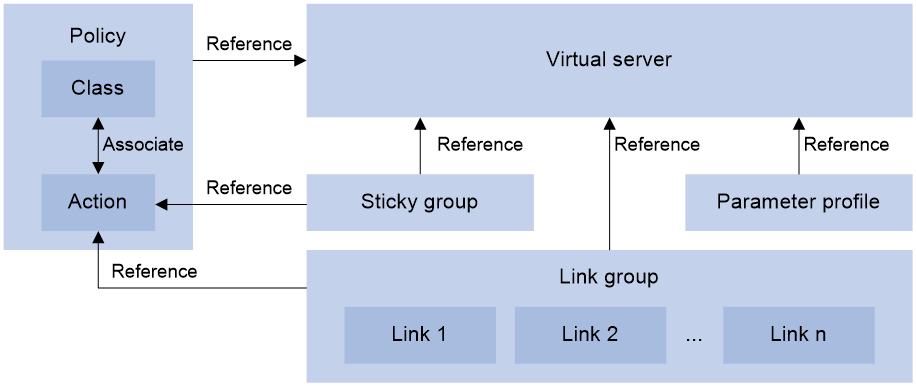
Tasks at a glance
To configure outbound link load balancing, perform the following tasks:
3. Configuring a virtual server
4. (Optional.) Configuring an LB policy
5. (Optional.) Configuring a sticky group
6. (Optional.) Configuring a parameter profile
7. (Optional.) Configuring ISP information
8. (Optional.) Setting the aging time for DNS cache entries
9. (Optional.) Configuring the ALG feature
10. (Optional.) Performing a load balancing test
11. (Optional.) Configuring SNMP notifications and logging for load balancing
¡ Enabling load balancing logging
Configuring a link group
You can add links that contain similar functions to a link group to facilitate management.
Link group tasks at a glance
To configure a link group, perform the following tasks:
2. (Optional.) Adding and configuring a link group member
3. Configuring a scheduling algorithm for a link group
4. Setting the availability criteria
6. (Optional.) Configuring SNAT
7. (Optional.) Enabling the slow online feature
8. (Optional.) Configuring health monitoring
9. (Optional.) Specifying a fault processing method
10. (Optional.) Configuring the proximity feature
Creating a link group
1. Enter system view.
system-view
2. Create a link group and enter link group view.
loadbalance link-group link-group-name
3. (Optional.) Configure a description for the link group.
description text
By default, no description is configured for a link group.
Adding and configuring a link group member
About this task
Perform this task to create a link group member or add an existing link as a link group member in link group view. You can also specify a link group for a link in link view to achieve the same purpose (see "Creating a link and specifying a link group").
After adding a link group member, you can configure the following parameters and features for the link in the link group:
· Weight.
· Priority.
· Connection limits.
· Health monitoring.
· Slow offline.
The member-based scheduling algorithm selects the best link based on these configurations.
Adding a link group member
1. Enter system view.
system-view
2. Enter link group view.
loadbalance link-group link-group-name
3. Create and add a link group member and enter link group member view.
link link-name
If the link already exists, the command adds the existing link as a link group member.
4. (Optional.) Configure a description for the link group member.
description text
By default, no description is configured for the link group member.
Setting the weight and priority of the link group member
1. Enter system view.
system-view
2. Enter link group view.
loadbalance link-group link-group-name
3. Enter link group member view.
link link-name
4. Set the weight of the link group member.
weight weight-value
The default setting is 100.
5. Set the priority of the link group member.
priority priority
The default setting is 4.
Setting the connection limits of the link group member
1. Enter system view.
system-view
2. Enter link group view.
loadbalance link-group link-group-name
3. Enter link group member view.
link link-name
4. Set the connection rate of the link group member.
rate-limit connection connection-number
The default setting is 0 (the connection rate is not limited).
5. Set the maximum number of connections allowed for the link group member.
connection-limit max max-number
The default setting is 0 (the maximum number of connections is not limited).
Configuring health monitoring for the link group member
1. Enter system view.
system-view
2. Enter link group view.
loadbalance link-group link-group-name
3. Enter link group member view.
link link-name
4. Specify a health monitoring method for the link group member.
probe template-name
By default, no health monitoring method is specified for the link group member.
You can specify an NQA template for health monitoring. For information about NQA templates, see NQA configuration in Network Management and Monitoring Configuration Guide.
5. Specify the health monitoring success criteria for the link group member.
success-criteria { all | at-least min-number }
By default, health monitoring succeeds only when all the specified health monitoring methods succeed.
Enabling the slow offline feature for the link group member
1. Enter system view.
system-view
2. Enter link group view.
loadbalance link-group link-group-name
3. Enter link group member view.
link link-name
4. Enable the slow offline feature for the link group member.
slow-shutdown enable
By default, the slow offline feature is disabled.
5. Shut down the link group member.
shutdown
By default, the link group member is activated.
Configuring a scheduling algorithm for a link group
About this task
Perform this task to specify a scheduling algorithm for a link group and specify the number of links to participate in scheduling. The LB device calculates the links to process user requests based on the specified scheduling algorithm.
The device provides the following scheduling algorithms for a link group:
· Weighted least connection algorithm (link-based)—Always assigns user requests to the link with the fewest number of weighted active connections (the total number of active connections in all link groups divided by weight). The weight value used in this algorithm is configured in real server view.
· Weighted least connection algorithm (link group member-based)—Always assigns user requests to the link with the fewest number of weighted active connections (the total number of active connections in the specified link group divided by weight). The weight value used in this algorithm is configured in link group member view.
· Random algorithm—Randomly assigns user requests to links.
· Round robin algorithm—Assigns user requests to links based on the weights of links. A higher weight indicates more user requests will be assigned.
· Bandwidth algorithm—Distributes user requests to links according to the weights and remaining bandwidth of links.
· Maximum bandwidth algorithm—Distributes user requests always to an idle link that has the largest remaining bandwidth.
· Source IP address hash algorithm—Hashes the source IP address of user requests and distributes user requests to different links according to the hash values.
· Source IP address and port hash algorithm—Hashes the source IP address and port number of user requests and distributes user requests to different links according to the hash values.
· Destination IP address hash algorithm—Hashes the destination IP address of user requests and distributes user requests to different links according to the hash values.
Procedure
1. Enter system view.
system-view
2. Enter link group view.
loadbalance link-group link-group-name
3. Specify a scheduling algorithm for the link group.
¡ Specify a link-based scheduling algorithm.
predictor { least-connection | { bandwidth | max-bandwidth } [ inbound | outbound ] }
¡ Specify a link group member-based scheduling algorithm.
predictor hash address { destination | source | source-ip-port } [ mask mask-length ] [ prefix prefix-length ]
predictor { least-connection member | random | round-robin }
By default, the scheduling algorithm for a link group is weighted round robin.
4. Specify the number of links to participate in scheduling.
selected-link min min-number max max-number
By default, the links with the highest priority participate in scheduling.
Setting the availability criteria
About this task
Perform this task to set the criteria (lower percentage and higher percentage) to determine whether a link group is available. This helps implement traffic switchover between the master and backup link groups.
· When the number of available links to the total number of links in the master link group is smaller than the lower percentage, traffic is switched to the backup link group.
· When the number of available links to the total number of links in the master link group is greater than the upper percentage, traffic is switched back to the master link group.
Procedure
1. Enter system view.
system-view
2. Enter link group view.
loadbalance link-group link-group-name
3. Set the criteria to determine whether the link group is available.
activate lower lower-percentage upper upper-percentage
By default, when a minimum of one link is available, the link group is available.
Disabling NAT
Restrictions and guidelines
Typically, outbound link load balancing networking requires disabling NAT for a link group.
Procedure
1. Enter system view.
system-view
2. Enter link group view.
loadbalance link-group link-group-name
3. Disable NAT for the link group.
transparent enable
By default, NAT is enabled for a link group.
Configuring SNAT
About this task
After a link group references the SNAT address pool, the LB device replaces the source address of the packets it receives with an SNAT address before forwarding the packets.
Restrictions and guidelines
An SNAT address pool can have multiple address ranges. Each address range can have a maximum of 256 IPv4 addresses or 65536 IPv6 addresses. No overlapping IPv4 or IPv6 addresses are allowed in the same SNAT address pool or different SNAT address pools.
As a best practice, do not use SNAT because its application scope is limited for outbound link load balancing.
Procedure
1. Enter system view.
system-view
2. Create a SNAT address pool and enter SNAT address pool view.
loadbalance snat-pool pool-name
3. (Optional.) Configure a description for the SNAT address pool.
description text
By default, no description is configured for a SNAT address pool.
4. Specify an address range for the SNAT address pool.
IPv4:
ip range start start-ipv4-address end end-ipv4-address
IPv6:
ipv6 range start start-ipv6-address end end-ipv6-address
By default, a SNAT address pool does not contain address ranges.
5. (Optional.) Specify a VPN instance for the SNAT address pool.
vpn-instance vpn-instance-name
By default, a SNAT address pool belongs to the public network.
Use this command to separate overlapping SNAT address pools.
6. Return to system view.
quit
7. Enter link group view.
loadbalance link-group link-group-name
8. Specify the SNAT address pool to be referenced by the link group.
snat-pool pool-name
By default, no SNAT address pool is referenced by a link group.
Enabling the slow online feature
About this task
Links newly added to a link group might be unable to immediately process large numbers of services assigned by the LB device. To resolve this issue, enable the slow online feature for the link group. The feature uses the standby timer and ramp-up timer. When the links are brought online, the LB device does not assign any services to the links until the standby timer expires.
When the standby timer expires, the ramp-up timer starts. During the ramp-up time, the LB device increases the service amount according to the processing capability of the links, until the ramp-up timer expires.
Procedure
1. Enter system view.
system-view
2. Enter link group view.
loadbalance link-group link-group-name
3. Enable the slow online feature for the link group.
slow-online [ standby-time standby-time ramp-up-time ramp-up-time ]
By default, the slow online feature is disabled for a link group.
Configuring health monitoring
About this task
Perform this task to enable health monitoring to detect the availability of links.
Restrictions and guidelines
The health monitoring configuration in link view takes precedence over the configuration in link group view.
You can specify an NQA template for health monitoring. For information about NQA templates, see NQA configuration in Network Management and Monitoring Configuration Guide.
Procedure
1. Enter system view.
system-view
2. Enter link group view.
loadbalance link-group link-group-name
3. Specify a health monitoring method for the link group.
probe template-name
By default, no health monitoring method is specified for a link group.
4. Specify the health monitoring success criteria for the link group.
success-criteria { all | at-least min-number }
By default, health monitoring succeeds only when all the specified health monitoring methods succeed.
Specifying a fault processing method
About this task
Perform this task to specify one of the following fault processing methods for a link group:
· Keep—Does not actively terminate the connection with the failed link. Keeping or terminating the connection depends on the timeout mechanism of the protocol.
· Reschedule—Redirects the connection to another available link in the link group.
· Reset—Terminates the connection with the failed link by sending RST packets (for TCP packets) or ICMP unreachable packets (for other types of packets).
Procedure
1. Enter system view.
system-view
2. Enter link group view.
loadbalance link-group link-group-name
3. Specify a fault processing method for the link group.
fail-action { keep | reschedule | reset }
By default, the fault processing method is keep. All available connections are kept.
Configuring the proximity feature
About this task
The proximity feature performs link detection to select the optimal link to a destination. If no proximity information for a destination is available, the load balancing module selects a link based on the scheduling algorithm. It then performs proximity detection to generate proximity entries for forwarding subsequent traffic.
You can specify an NQA template or load-balancing probe template to perform link detection. The device generates proximity entries according to the detection results and proximity parameter settings. For information about NQA templates, see NQA configuration in Network Management and Monitoring Configuration Guide.
Restrictions and guidelines
To configure the proximity feature, first configure proximity parameters in proximity view, and then enable the proximity feature in link group view.
Configuring an LB probe template
1. Enter system view.
system-view
2. Create an LB probe template and enter LB probe template view.
loadbalance probe-template icmp template-name
3. Set the probe interval.
frequency interval
The default setting is 300 seconds.
4. Set the timeout time for probe responses.
timeout timeout-value
The default setting is 3 seconds.
Configuring the proximity probe method
1. Enter system view.
system-view
2. Enter proximity view.
loadbalance proximity [ vpn-instance vpn-instance-name ]
3. Specify the proximity probe method for packets.
match [ match-id ] { tcp } { lb-probe lb-template | probe nqa-template }
By default, no proximity probe method is specified.
4. Specify the default proximity probe method.
match default { lb-probe lb-template | probe nqa-template }
By default, the default proximity probe method is not specified.
Configuring proximity parameters
1. Enter system view.
system-view
2. Enter proximity view.
loadbalance proximity [ vpn-instance vpn-instance-name ]
3. Set the mask length for IPv4 proximity entries.
ip mask { mask-length | mask }
By default, the mask length for IPv4 proximity entries is 24.
4. Set the prefix length for IPv6 proximity entries.
ipv6 prefix prefix-length
By default, the prefix length for IPv6 proximity entries is 96.
5. Set the network delay weight for proximity calculation.
rtt weight rtt-weight
By default, the network delay weight for proximity calculation is 100.
6. Set the TTL weight for proximity calculation.
ttl weight ttl-weight
By default, the TTL weight for proximity calculation is 100.
7. Set the bandwidth weight for proximity calculation.
bandwidth { inbound | outbound } weight bandwidth-weight
By default, the inbound or outbound bandwidth weight for proximity calculation is 100.
8. Set the cost weight for proximity calculation.
cost weight cost-weight
By default, the cost weight for proximity calculation is 100.
9. Set the aging timer for proximity entries.
timeout timeout-value
By default, the aging timer for proximity entries is 60 seconds.
10. Set the maximum number of proximity entries.
max-number number
By default, the maximum number of proximity entries is 65535.
Enabling the proximity feature
1. Enter system view.
system-view
2. Enter link group view.
loadbalance link-group link-group-name
3. Enable the proximity feature.
proximity enable
By default, the proximity feature is disabled for a link group.
Configuring a link
A link is a physical link provided by an ISP. A link can belong to multiple link groups. A link group can have multiple links.
Restrictions and guidelines
In a network where hot backup cooperates with VRRP, as a best practice, make sure the IP address of the link-attached output interface is on the same network segment as the virtual IP address of the VRRP group. For more information about hot backup and VRRP association, see hot backup configuration in High Availability Configuration Guide.
Link tasks at a glance
To configure a link, perform the following tasks:
1. Creating a link and specifying a link group
2. Specifying a next hop IP address or an outgoing interface
Choose one of the following tasks:
¡ Specifying an outbound next hop for a link
¡ Specifying an outgoing interface for a link
3. Setting a weight and priority
4. (Optional.) Configuring the bandwidth and connection parameters
5. (Optional.) Configuring health monitoring
6. (Optional.) Enabling the slow offline feature
7. (Optional.) Setting the link cost for proximity calculation
8. (Optional.) Setting the bandwidth ratio and maximum expected bandwidth
9. (Optional.) Disabling VPN instance inheritance for a link
Creating a link and specifying a link group
1. Enter system view.
system-view
2. Create a link and enter link view.
loadbalance link link-name
By default, no links exist.
3. (Optional.) Configure a description for the link.
description text
By default, no description is configured for a link.
4. Specify a link group for the link.
link-group link-group-name
By default, a link does not belong to any link group.
Specifying an outbound next hop for a link
1. Enter system view.
system-view
2. Enter link view.
loadbalance link link-name
3. Specify an outbound next hop for the link.
IPv4:
router ip ipv4-address
IPv6:
router ipv6 ipv6-address
By default, a link does not have an outbound next hop.
Specifying an outgoing interface for a link
About this task
In scenarios where IP addresses are obtained through PPPoE, an LB device can dynamically obtain the outbound next hop IP address through the specified outgoing interface.
Procedure
1. Enter system view.
system-view
2. Enter link view.
loadbalance link link-name
3. Specify an outgoing interface for the link.
router interface interface-type interface-number
By default, no outgoing interface is specified for a link.
Setting a weight and priority
About this task
Perform this task to configure a weight for the weighted round robin and weighted least connection algorithms of a link, and the scheduling priority in the link group for the server.
Procedure
1. Enter system view.
system-view
2. Enter link view.
loadbalance link link-name
3. Set a weight for the link.
weight weight-value
By default, the weight of a link is 100.
4. Set a priority for the link.
priority priority
By default, the priority of a link is 4.
Configuring the bandwidth and connection parameters
1. Enter system view.
system-view
2. Enter link view.
loadbalance link link-name
3. Set the maximum bandwidth for the link.
rate-limit bandwidth [ inbound | outbound ] bandwidth-value kbps
By default, the maximum bandwidth, inbound bandwidth, and outbound bandwidth are 0 for a link. The bandwidths are not limited.
4. Set the maximum number of connections for the link.
connection-limit max max-number
By default, the maximum number of connections is 0 for a link. The number is not limited.
5. Set the maximum number of connections per second for the link.
rate-limit connection connection-number
By default, the maximum number of connections per second is 0 for a link. The number is not limited.
Configuring health monitoring
About this task
Perform this task to enable health monitoring to detect the availability of a link.
Restrictions and guidelines
The health monitoring configuration in link view takes precedence over the configuration in link group view.
Procedure
1. Enter system view.
system-view
2. Enter link view.
loadbalance link link-name
3. Specify a health monitoring method for the link.
probe template-name
By default, no health monitoring method is specified for a link.
4. Specify the health monitoring success criteria for the link.
success-criteria { all | at-least min-number }
By default, the health monitoring succeeds only when all the specified health monitoring methods succeed.
Enabling the slow offline feature
About this task
The shutdown command immediately terminates existing connections of a link. The slow offline feature ages out the connections, and does not establish new connections.
Restrictions and guidelines
To enable the slow offline feature for a link, you must execute the slow-shutdown enable command and then the shutdown command. If you execute the shutdown command and then the slow-shutdown enable command, the slow offline feature does not take effect and the link is shut down.
Procedure
1. Enter system view.
system-view
2. Enter link view.
loadbalance link link-name
3. Enable the slow offline feature for the link.
slow-shutdown enable
By default, the slow offline feature is disabled.
4. Shut down the link.
shutdown
By default, the link is activated.
Setting the link cost for proximity calculation
1. Enter system view.
system-view
2. Enter link view.
loadbalance link link-name
3. Set the link cost for proximity calculation.
cost cost-value
By default, the link cost for proximity calculation is 0.
Setting the bandwidth ratio and maximum expected bandwidth
About this task
When the traffic exceeds the maximum expected bandwidth multiplied by the bandwidth ratio of a link, new traffic (traffic that does not match any sticky entries) is not distributed to the link. When the traffic drops below the maximum expected bandwidth multiplied by the bandwidth recovery ratio of the link, the link participates in scheduling again.
In addition to being used for link protection, the maximum expected bandwidth is used for remaining bandwidth calculation in the bandwidth algorithm, maximum bandwidth algorithm, and dynamic proximity algorithm.
Procedure
1. Enter system view.
system-view
2. Enter link view.
loadbalance link link-name
3. Set the bandwidth ratio.
bandwidth [ inbound | outbound ] busy-rate busy-rate-number [ recovery recovery-rate-number ]
By default, the total bandwidth ratio is 70.
4. Set the maximum expected bandwidth.
max-bandwidth [ inbound | outbound ] bandwidth-value kbps
By default, the maximum expected bandwidth, maximum uplink expected bandwidth, and maximum downlink expected bandwidth are 0. The bandwidths are not limited.
Disabling VPN instance inheritance for a link
About this task
When VPN instance inheritance is enabled, a link without a VPN instance specified inherits the VPN instance of the virtual server. When VPN instance inheritance is disabled, a link without a VPN instance specified belongs to the public network.
Procedure
1. Enter system view.
system-view
2. Enter link view.
loadbalance link link-name
3. Disable VPN instance inheritance for the link.
inherit vpn-instance disable
By default, VPN instance inheritance is enabled for a link.
Configuring a virtual server
A virtual server is a virtual service provided by the LB device to determine whether to perform load balancing for packets received on the LB device. Only the packets that match a virtual server are load balanced.
Restrictions and guidelines
Outbound link load balancing supports only the link-IP virtual server.
Virtual server tasks at a glance
To configure a virtual server, perform the following tasks:
2. Specifying the VSIP and port number
3. (Optional.) Specifying a VPN instance
4. Configuring a packet processing policy
Choose the following tasks as needed:
5. (Optional.) Specifying a parameter profile
6. (Optional.) Configuring the bandwidth and connection parameters
7. (Optional.) Enabling the link protection feature
8. (Optional.) Enabling bandwidth statistics collection by interfaces
9. (Optional.) Specifying a DPI application profile
10. (Optional.) Configuring hot backup
Creating a virtual server
1. Enter system view.
system-view
2. Create a link-IP virtual server and enter virtual server view.
virtual-server virtual-server-name type link-ip
3. (Optional.) Configure a description for the virtual server.
description text
By default, no description is configured for the virtual server.
Specifying the VSIP and port number
1. Enter system view.
system-view
2. Enter link-IP virtual server view.
virtual-server virtual-server-name
3. Specify the VSIP for the virtual server.
IPv4:
virtual ip address ipv4-address [ mask-length | mask ]
IPv6:
virtual ipv6 address ipv6-address [ prefix-length ]
By default, no IPv4 or IPv6 address is specified for a virtual server.
4. Specify the port number for the virtual server.
port port-number
By default, the port number is 0 (meaning any port number) for a link-IP virtual server.
Specifying a VPN instance
1. Enter system view.
system-view
2. Enter virtual server view.
virtual-server virtual-server-name
3. Specify a VPN instance for the virtual server.
vpn-instance vpn-instance-name
By default, a virtual server belongs to the public network.
Specifying link groups
About this task
When the primary link group is available (contains available links), the virtual server forwards packets through the primary link group. When the primary link group is not available, the virtual server forwards packets through the backup link group.
Procedure
1. Enter system view.
system-view
2. Enter virtual server view.
virtual-server virtual-server-name
3. Specify link groups.
default link-group link-group-name [ backup backup-link-group-name ] [ sticky sticky-name ]
By default, no link group is specified for a virtual server.
Specifying an LB policy
About this task
By referencing an LB policy, the virtual server load balances matching packets based on the packet contents.
Procedure
1. Enter system view.
system-view
2. Enter virtual server view.
virtual-server virtual-server-name
3. Specify an LB policy for the virtual server.
lb-policy policy-name
By default, the virtual server does not reference any LB policies.
A virtual server can only reference a policy profile of the specified type. For example, a virtual server of the link-IP type can only reference a policy profile of the link-generic type.
Specifying a parameter profile
About this task
You can configure advanced parameters through a parameter profile. The virtual server references the parameter profile to analyze, process, and optimize service traffic.
Procedure
1. Enter system view.
system-view
2. Enter virtual server view.
virtual-server virtual-server-name
3. Specify a parameter profile for the virtual server.
parameter ip profile-name
By default, the virtual server does not reference any parameter profiles.
Configuring the bandwidth and connection parameters
1. Enter system view.
system-view
2. Enter virtual server view.
virtual-server virtual-server-name
3. Set the maximum bandwidth for the virtual server.
rate-limit bandwidth [ inbound | outbound ] bandwidth-value kbps
By default, the maximum bandwidth, inbound bandwidth, and outbound bandwidth for the virtual server are 0. The bandwidths are not limited.
4. Set the maximum number of connections for the virtual server.
connection-limit max max-number
By default, the maximum number of connections of the virtual server is 0. The number is not limited.
5. Set the maximum number of connections per second for the virtual server.
rate-limit connection connection-number
By default, the maximum number of connections per second for the virtual server is 0. The number is not limited.
Enabling the link protection feature
About this task
The link protection feature limits packets that exceed the bandwidth busy rate in the inbound or outbound direction of a link. When a link is busy in only the outbound direction, new traffic (traffic that does not match any sticky entry) is not distributed to the link. However, existing traffic is still distributed to the link. When a link is busy in only the inbound direction, new traffic can be distributed to the link.
When a link becomes busy in at least one direction, the link state becomes busy. When a link is not busy in both directions, the link sate is normal.
Restrictions and guidelines
This feature takes effect only when bandwidth statistics collection by interfaces is enabled.
Procedure
1. Enter system view.
system-view
2. Enter virtual server view.
virtual-server virtual-server-name
3. Enable the link protection feature.
bandwidth busy-protection enable
By default, the link protection feature is disabled.
Enabling bandwidth statistics collection by interfaces
About this task
By default, the load balancing module automatically collects link bandwidth statistics. Perform this task to enable interfaces to collect bandwidth statistics.
Procedure
1. Enter system view.
system-view
2. Enter virtual server view.
virtual-server virtual-server-name
3. Enable bandwidth statistics collection by interfaces.
bandwidth interface statistics enable
By default, bandwidth statistics collection by interfaces is disabled.
Specifying a DPI application profile
About this task
This task allows you to perform DPI on the traffic of a virtual server, including IPS, anti-virus, and WAF. DPI helps you identify network attacks and security risks to secure the LB device and internal servers. For more information about DPI application profiles, see DPI engine in DPI Configuration Guide.
Procedure
1. Enter system view.
system-view
2. Enter virtual server view.
virtual-server virtual-server-name
3. Specify a DPI application profile for the virtual server.
dpi-app-profile dpi-app-profile-name
By default, a virtual server does not reference any DPI application profiles.
Configuring hot backup
About this task
To implement hot backup for two LB devices, you must enable synchronization for session extension information and sticky entries to avoid service interruption.
Restrictions and guidelines
For successful sticky entry synchronization, if you want to specify a sticky group, enable sticky entry synchronization before specifying a sticky group on both LB devices. You can specify a sticky group by using the sticky sticky-name option when specifying link groups.
In a VRRP network, you must specify the global keyword for the sticky entry synchronization feature to take effect.
The following configuration changes will cause the device to delete existing sticky entries and generate new ones based on subsequent traffic:
· Disable sticky entry synchronization.
· Change the sticky entry synchronization type.
Procedure
1. Enter system view.
system-view
2. Enter virtual server view.
virtual-server virtual-server-name
3. Enable session extension information synchronization.
connection-sync enable
By default, session extension information synchronization is disabled.
4. Enable sticky entry synchronization.
sticky-sync enable [ global ]
By default, sticky entry synchronization is disabled.
Enabling a virtual server
About this task
After you configure a virtual server, you must enable the virtual server for it to work.
Procedure
1. Enter system view.
system-view
2. Enter virtual server view.
virtual-server virtual-server-name
3. Enable the virtual server.
service enable
By default, the virtual server is disabled.
Configuring an LB class
An LB class classifies packets by comparing packets against specific rules. Matching packets are further processed by LB actions. You can create a maximum of 65535 rules for an LB class.
LB class tasks at a glance
To configure an LB class, perform the following tasks:
2. Creating a match rule
Choose the following tasks as needed:
¡ Creating a match rule that references an LB class
¡ Creating a source IP address match rule
¡ Creating a destination IP address match rule
¡ Creating an input interface match rule
¡ Creating a user group match rule
¡ Creating a domain name match rule
¡ Creating an application group match rule
Creating an LB class
1. Enter system view.
system-view
2. Create a link-generic LB class, and enter LB class view.
loadbalance class class-name type link-generic [ match-all | match-any ]
When you create an LB class, you must specify the class type. You can enter an existing LB class view without specifying the class type. If you specify the class type when entering an existing LB class view, the class type must be the one specified when you create the LB class.
3. (Optional.) Configure a description for the LB class.
description text
By default, no description is configured for the LB class.
Creating a match rule that references an LB class
1. Enter system view.
system-view
2. Enter LB class view.
loadbalance class class-name
3. Create a match rule that references an LB class.
match [ match-id ] class class-name
Creating a source IP address match rule
1. Enter system view.
system-view
2. Enter LB class view.
loadbalance class class-name
3. Create a source IP address match rule.
match [ match-id ] source { ip address ipv4-address [ mask-length | mask ] | ipv6 address ipv6-address [ prefix-length ] }
Creating a destination IP address match rule
1. Enter system view.
system-view
2. Enter LB class view.
loadbalance class class-name
3. Create a destination IP address match rule.
match [ match-id ] destination { ip address ipv4-address [ mask-length | mask ] | ipv6 address ipv6-address [ prefix-length ] }
Creating an ACL match rule
1. Enter system view.
system-view
2. Enter LB class view.
loadbalance class class-name
3. Create an ACL match rule.
match [ match-id ] acl [ ipv6 ] { acl-number | name acl-name }
Creating an input interface match rule
1. Enter system view.
system-view
2. Enter LB class view.
loadbalance class class-name
3. Create an input interface match rule.
match [ match-id ] interface interface-type interface-number
Creating a user match rule
1. Enter system view.
system-view
2. Enter LB class view.
loadbalance class class-name
3. Create a user match rule.
match [ match-id ] [ identity-domain domain-name ] user user-name
Creating a user group match rule
1. Enter system view.
system-view
2. Enter LB class view.
loadbalance class class-name
3. Create a user group match rule.
match [ match-id ] [ identity-domain domain-name ] user-group user-group-name
Creating a domain name match rule
About this task
The LB device stores mappings between domain names and IP addresses in the DNS cache. If the destination IP address of an incoming packet matches an IP address in the DNS cache, the LB device queries the domain name for the IP address. If the queried domain name matches the domain name configured in a match rule, the LB device takes the LB action on the packet.
Procedure
1. Enter system view.
system-view
2. Enter LB class view.
loadbalance class class-name
3. Create a domain name match rule.
match [ match-id ] destination domain-name domain-name
By default, an LB class does not have any match rules.
Creating an ISP match rule
1. Enter system view.
system-view
2. Enter LB class view.
loadbalance class class-name
3. Create an ISP match rule.
match [ match-id ] isp isp-name
Creating an application group match rule
1. Enter system view.
system-view
2. Enter LB class view.
loadbalance class class-name
3. Create an application group match rule.
match [ match-id ] app-group group-name
After you execute this configuration, hardware fast forwarding cannot process traffic processed by outbound link load balancing.
Configuring an LB action
About LB actions
LB actions include the following modes:
· Forwarding mode—Determines whether and how to forward packets. If no forwarding action is specified, packets are dropped.
· Modification mode—Modifies packets. To prevent the LB device from dropping the modified packets, the modification action must be used together with a forwarding action.
If you create an LB action without specifying any of the previous action modes, packets are dropped.
Restrictions and guidelines
The "Configuring the forwarding mode" and "Specifying link groups" tasks are mutually exclusive. Configuring one task automatically cancels the other task that you have configured.
LB action tasks at a glance
To configure an LB action, perform the following tasks:
2. (Optional.) Configuring a forwarding LB action
¡ Configuring the forwarding mode
¡ (Optional.) Matching the next rule upon failure to find a link
¡ (Optional.) Matching the next rule when all links are busy
3. (Optional.) Configuring a modification LB action
¡ Configuring the ToS field in IP packets sent to the server
Creating an LB action
1. Enter system view.
system-view
2. Create a link-generic LB action and enter LB action view.
loadbalance action action-name type link-generic
When you create an LB action, you must specify the action type. You can enter an existing LB action view without specifying the action type. If you specify the action type when entering an existing LB action view, the action type must be the one specified when you create the LB action.
3. (Optional.) Configure a description for the LB action.
description text
By default, no description is configured for the LB action.
Configuring a forwarding LB action
About this task
Three forwarding LB action types are available:
· Forward—Forwards matching packets.
· Specify link groups—When the primary link group is available (contains available real servers), the primary link group is used to guide packet forwarding. When the primary link group is not available, the backup link group is used to guide packet forwarding.
· Match the next rule upon failure to find a link—If the device fails to find a link according to the LB action, it matches the packet with the next rule in the LB policy.
· Match the next rule when all links are busy.
Configuring the forwarding mode
1. Enter system view.
system-view
2. Enter LB action view.
loadbalance action action-name
3. Configure the forwarding mode.
forward all
By default, the forwarding mode is to discard packets.
Specifying link groups
1. Enter system view.
system-view
2. Enter LB action view.
loadbalance action action-name
3. Specify link groups.
link-group link-group-name [ backup backup-link-group-name ] [ sticky sticky-name ]
By default, no link group is specified.
Matching the next rule upon failure to find a link
1. Enter system view.
system-view
2. Enter LB action view.
loadbalance action action-name
3. Match the next rule upon failure to find a link.
fallback-action continue
By default, the next rule is not matched when no links are available for the current LB action.
This command does not apply to SIP virtual servers.
Matching the next rule when all links are busy
1. Enter system view.
system-view
2. Enter LB action view.
loadbalance action action-name
3. Match the next rule when all links are busy.
busy-action continue
By default, the device assigns packets to links regardless of whether they are busy.
Configuring the ToS field in IP packets sent to the server
1. Enter system view.
system-view
2. Enter LB action view.
loadbalance action action-name
3. Configure the ToS field in IP packets sent to the server.
set ip tos tos-number
By default, the ToS field in IP packets sent to the server is not changed.
Configuring an LB policy
About LB policies
An LB policy associates an LB class with an LB action to guide packet forwarding. In an LB policy, you can configure an LB action for packets matching the specified LB class, and configure the default action for packets matching no LB class.
You can specify multiple LB classes for an LB policy. Packets match the LB classes in the order the LB classes are configured. If an LB class is matched, the specified LB action is performed. If no LB class is matched, the default LB action is performed.
LB policy tasks at a glance
To configure an LB policy, perform the following tasks:
3. Specifying the default LB action
Creating an LB policy
1. Enter system view.
system-view
2. Create a link-generic LB policy, and enter LB action view.
loadbalance policy policy-name type link-generic
When you create an LB policy, you must specify the policy type. You can enter an existing LB policy view without specifying the policy type. If you specify the policy type when entering an existing LB policy view, the policy type must be the one specified when you create the LB policy.
3. (Optional.) Configure a description for the LB policy.
description text
By default, no description is configured for an LB policy.
Specifying an LB action
Restrictions and guidelines
A link-generic LB policy can reference only link-generic LB classes and link-generic LB actions.
Procedure
1. Enter system view.
system-view
2. Enter LB policy view.
loadbalance policy policy-name
3. Specify an LB action for the specified LB class.
class class-name [ insert-before before-class-name | insert-after [ after-class-name ] ] action action-name
By default, no LB action is specified for any LB classes.
You can specify an LB action for different LB classes.
Specifying the default LB action
Restrictions and guidelines
A link-generic LB policy can only reference link-generic LB actions.
Procedure
1. Enter system view.
system-view
2. Enter LB policy view.
loadbalance policy policy-name
3. Specify the default LB action.
default-class action action-name
By default, no default LB action is specified.
Configuring a sticky group
A sticky group uses a sticky method to distribute similar sessions to the same link according to sticky entries. The sticky method applies to the first packet of a session. Other packets of the session are distributed to the same link.
Sticky group tasks at a glance
To configure a sticky group, perform the following tasks:
2. Configuring the IP sticky method
3. (Optional.) Configuring the timeout time for sticky entries
4. (Optional.) Ignoring the limits for sessions that match sticky entries
5. (Optional.) Enabling stickiness-over-busyness
Creating a sticky group
1. Enter system view.
system-view
2. Create an address- and port-type sticky group and enter sticky group view.
sticky-group group-name type address-port
When you create a sticky group, you must specify the group type. You can enter an existing sticky group view without specifying the group type. If you specify the group type when entering an existing sticky group view, the group type must be the one specified when you create the sticky group.
3. (Optional.) Configure a description for the sticky group.
description text
By default, no description is configured for the sticky group.
Configuring the IP sticky method
1. Enter system view.
system-view
2. Enter sticky group view.
sticky-group group-name
3. Configure the IP sticky method.
IPv4:
ip [ port ] { both | destination | source } [ mask mask-length ]
IPv6:
ipv6 [ port ] { both | destination | source } [ prefix prefix-length ]
By default, no IP sticky method is configured.
Configuring the timeout time for sticky entries
1. Enter system view.
system-view
2. Enter sticky group view.
sticky-group group-name
3. Configure the timeout time for sticky entries.
timeout timeout-value
By default, the timeout time for sticky entries is 60 seconds.
Ignoring the limits for sessions that match sticky entries
About this task
Perform this task to ignore the following limits for sessions that match sticky entries:
· Bandwidth and connection parameters on links.
· LB connection limit policies on virtual servers.
Procedure
1. Enter system view.
system-view
2. Enter sticky group view.
sticky-group group-name
3. Ignore the limits for sessions that match sticky entries.
override-limit enable
By default, the session limits apply to sessions that match sticky entries.
Enabling stickiness-over-busyness
About stickiness-over-busyness
This feature enables the device to assign client requests to links based on sticky entries, regardless of whether the links are busy.
When this feature is disabled, the device assigns client requests to only links in normal state.
Procedure
1. Enter system view.
system-view
2. Enter sticky group view.
sticky-group group-name
3. Enable stickiness-over-busyness.
sticky-over-busy enable
By default, stickiness-over-busyness is disabled.
Configuring a parameter profile
About configuring a parameter profile
You can configure advanced parameters through a parameter profile. The virtual server references the parameter profile to analyze, process, and optimize service traffic.
Creating a parameter profile
1. Enter system view.
system-view
2. Create an IP-type parameter profile and enter parameter profile view.
parameter-profile profile-name type ip
By default, no parameter profiles exist.
When you create a parameter profile, you must specify the profile type. You can enter an existing parameter profile view without specifying the profile type. If you specify the profile type when entering an existing parameter profile view, the profile type must be the one specified when you create the parameter profile.
3. (Optional.) Configure a description for the parameter profile.
description text
By default, no description is configured for the parameter profile.
Configuring the ToS field in IP packets sent to the client
1. Enter system view.
system-view
2. Enter IP parameter profile view.
parameter-profile profile-name
3. Configure the ToS field in IP packets sent to the client.
set ip tos tos-number
By default, the ToS field in IP packets sent to the client is not changed.
Configuring ISP information
About configuring ISP information
Perform this task to configure IP address information for an ISP. The IP address information can be used by an ISP match rule. When the destination IP address of packets matches the ISP match rule of an LB class, the LB device takes the action associated with the class. The device supports the following methods to configure IP address information:
· Manual configuration—The administrator manually specifies IP address information.
· ISP auto update—With ISP auto update enabled, the device regularly queries IP address information from the whois server according to the whois maintainer object of the ISP.
· ISP file import—The administrator manually imports an ISP file in .tp format. The ISP file can be obtained from the official website.
Restrictions and guidelines
You can configure ISP information manually, by importing an ISP file, by auto update, or use the combination of these methods..
Configuring ISP information manually
1. Enter system view.
system-view
2. Create an ISP and enter ISP view.
loadbalance isp name isp-name
3. Specify the IP address for the ISP.
IPv4:
ip address ipv4-address { mask-length | mask }
IPv6:
ipv6 address ipv6-address prefix-length
By default, an ISP does not contain IPv4 or IPv6 addresses.
An ISP does not allow overlapping network segments.
4. (Optional.) Configure a description for the ISP.
description text
By default, no description is configured for the ISP.
Configuring ISP auto update
1. Enter system view.
system-view
2. Create an ISP and enter ISP view.
loadbalance isp name isp-name
3. Specify a whois maintainer object for the ISP.
whois-mntner mntner-name
By default, no whois maintainer object is specified.
You can specify a maximum of 10 whois maintainer objects for an ISP.
4. Return to system view.
quit
5. Enable ISP auto update.
loadbalance isp auto-update enable
By default, ISP auto update is disabled.
6. Configure the ISP auto update frequency.
loadbalance isp auto-update frequency { per-day | per-week | per-month }
By default, the ISP auto update is performed once per week.
7. Specify the whois server to be queried for ISP auto update.
loadbalance isp auto-update whois-server { domain domain-name | ip ip-address }
By default, no whois server is specified for ISP auto update.
Importing an ISP file
1. Enter system view.
system-view
2. Import an ISP file.
loadbalance isp file isp-file-name
Setting the aging time for DNS cache entries
About this task
A DNS cache entry records the mapping between a domain name and the IP address of the outbound next hop.
Procedure
1. Enter system view.
system-view
2. Set the aging time for DNS cache entries.
loadbalance dns-cache aging-time aging-time
By default, the aging time for DNS cache entries is 60 minutes.
Configuring the ALG feature
About this task
The Application Level Gateway (ALG) feature distributes parent and child sessions to the same link.
Procedure
1. Enter system view.
system-view
2. Enable ALG.
¡ Enable
ALG for the specified protocol:
loadbalance
alg { dns | ftp | h323 | icmp-error | ils | mgcp | nbt | pptp | rsh | rtsp | sccp | sip | sqlnet | tftp | xdmcp }
¡ Enable ALG for all protocols:
loadbalance
alg all-enable
By default, ALG is enabled for the DNS, FTP, PPTP, and RTSP protocols and ICMP error packets.
Performing a load balancing test
About performing a load balancing test
Perform this task in any view to test the load balancing result.
Performing an IPv4 load balancing test
To perform an IPv4 load balancing test, execute the following command in any view:
loadbalance schedule-test ip [ vpn-instance vpn-instance-name ] { application http { message-file file-name | method { get | post } url url [ header header ]&<1-10> [ content content-value ] } | protocol { protocol-number | icmp | tcp | udp } } destination destination-address destination-port destination-port source source-address source-port source-port [ slot slot-number ]
Performing an IPv6 load balancing test
To perform an IPv6 load balancing test, execute the following command in any view:
loadbalance schedule-test ipv6 [ vpn-instance vpn-instance-name ] { application http { message-file file-name | method { get | post } url url [ header header ]&<1-10> [ content content-value ] } | protocol { protocol-number | icmpv6 | tcp | udp } } destination destination-address destination-port destination-port source source-address source-port source-port [ slot slot-number ]
Enabling SNMP notifications
About this task
To report critical load balancing events to an NMS, enable SNMP notifications for load balancing. For load balancing event notifications to be sent correctly, you must also configure SNMP as described in Network Management and Monitoring Configuration Guide.
The SNMP notifications configuration tasks for Layer 4 and Layer 7 server load balancing are the same.
Procedure
1. Enter system view.
system-view
2. Enable SNMP notifications for load balancing.
snmp-agent trap enable loadbalance
By default, SNMP notifications are enabled for load balancing.
Enabling load balancing logging
About load balancing logging
For security auditing purposes, enable load balancing logging to record load balancing information. Load balancing logging includes the following types:
· Basic logging.
· Link flow logging.
· NAT logging.
· Link busy state logging.
Basic logging generates logs for the following events:
· The state of a link or link group changes.
· The health monitoring result of a link changes.
· The number of connections on a link or virtual server reaches or drops below the upper limit.
· The connection establishment rate on a link or virtual server reaches or drops below the upper limit.
· A primary/backup server farm switchover occurs between server farms specified for a virtual server.
· A primary/backup server farm switchover occurs between server farms specified for an LB action.
Link flow logging records flows forwarded through all links.
NAT logging records NAT session information, including IP address and port translation information and access information.
Link busy state logging records busy states for all links.
Enabling load balancing basic logging
1. Enter system view.
system-view
2. Enable load balancing basic logging.
loadbalance log enable base
By default, load balancing basic logging is enabled.
Enabling load balancing link flow logging
1. Enter system view.
system-view
2. Enable load balancing link flow logging.
loadbalance log enable link-flow
By default, load balancing link flow logging is enabled.
Enabling load balancing NAT logging
1. Enter system view.
system-view
2. Enable load balancing NAT logging.
loadbalance log enable nat
By default, load balancing NAT logging is disabled.
Enabling load balancing link busy state logging
1. Enter system view.
system-view
2. Enable load balancing link busy state logging.
loadbalance log enable bandwidth-busy
By default, load balancing link busy state logging is disabled.
Displaying and maintaining outbound link load balancing
Execute display commands in any view and reset commands in user view.
|
Task |
Command |
|
Display LB action information. |
display loadbalance action [ name action-name ] |
|
Display LB class information. |
display loadbalance class [ name class-name ] |
|
Display LB hot backup statistics. |
display loadbalance hot-backup statistics [ slot slot-number ] |
|
Display ISP information. |
display loadbalance isp [ ip ipv4-address | ipv6 ipv6-address | name isp-name ] |
|
Display LB policy information. |
display loadbalance policy [ name policy-name ] |
|
Display proximity entry information. |
display loadbalance proximity [ vpn-instance vpn-instance-name ] [ ip [ ipv4-address ] | ipv6 [ ipv6-address ] ] [ slot slot-number ] |
|
Display parameter profile information. |
display parameter-profile [ name parameter-name ] |
|
Display link information. |
display loadbalance link [ brief | name link-name ] |
|
Display link group member information. |
display loadbalance link link-group link-group-name [ name link-name ] |
|
Display link statistics. |
display loadbalance link statistics [ name link-name ] [ slot slot-number ] |
|
Display link group member statistics. |
display loadbalance link statistics link-group link-group-name [ name link-name ] [ slot slot-number ] |
|
Display link outbound interface statistics. |
display loadbalance link out-interface statistics [ name link-name ] |
|
Display link group information. |
display loadbalance link-group [ brief | name link-group-name ] |
|
Display sticky entry information. |
display sticky virtual-server [ virtual-server-name ] [ class class-name | default-class | default-link-group ] [ slot slot-number ] |
|
Display sticky group information. |
display sticky-group [ name group-name ] |
|
Display virtual server information. |
display virtual-server [ brief | name virtual-server-name ] |
|
Display virtual server statistics. |
display virtual-server statistics [ name virtual-server-name ] [ slot slot-number ] |
|
Display the ALG status for all protocols. |
|
|
Display DNS cache information. |
display loadbalance dns-cache [ vpn-instance vpn-instance-name ] [ domain-name domain-name ] [ slot slot-number ] |
|
Clear LB hot backup statistics. |
reset loadbalance hot-backup statistics |
|
Clear proximity entry information. |
reset loadbalance proximity [ vpn-instance vpn-instance-name ] [ ip [ ipv4-address ] | ipv6 [ ipv6-address ] ] |
|
Clear all Layer 7 connections. |
reset loadbalance connections |
|
Clear link statistics. |
reset loadbalance link statistics [ link-name ] |
|
Clear link group member statistics. |
reset loadbalance link statistics link-group link-group-name [ name link-name ] |
|
Clear virtual server statistics. |
reset virtual-server statistics [ virtual-server-name ] |
|
Clear DNS cache information. |
reset loadbalance dns-cache [ vpn-instance vpn-instance-name ] [ domain-name domain-name ] |
Outbound link load balancing configuration examples
Example: Configuring outbound link load balancing
Network configuration
In Figure 18, ISP 1 and ISP 2 provide two links, Link 1 and Link 2, with the same router hop count, bandwidth, and cost. Link 1 has lower network delay.
Configure link load balancing for the device to select an optimal link for traffic from the client host to the server.
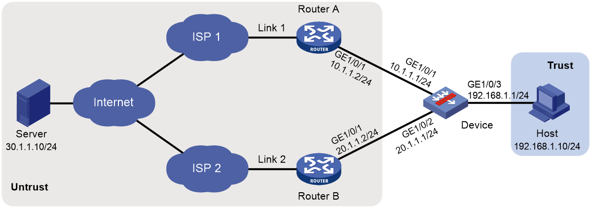
Procedure
1. Assign IP addresses to interfaces:
# Assign an IP address to interface GigabitEthernet 1/0/1.
<Device> system-view
[Device] interface gigabitethernet 1/0/1
[Device-GigabitEthernet1/0/1] ip address 10.1.1.1 255.255.255.0
[Device-GigabitEthernet1/0/1] quit
# Assign IP addresses to other interfaces in the same way. (Details not shown.)
2. Add interfaces to security zones.
[Device] security-zone name untrust
[Device-security-zone-Untrust] import interface gigabitethernet 1/0/1
[Device-security-zone-Untrust] import interface gigabitethernet 1/0/2
[Device-security-zone-Untrust] quit
[Device] security-zone name trust
[Device-security-zone-Trust] import interface gigabitethernet 1/0/3
[Device-security-zone-Trust] quit
3. Configure a security policy:
Configure rules to permit traffic from the Trust security zone to the Untrust security zone and traffic from the Local security zone to the Untrust security zone, so the users can access the server:
# Configure a rule named lbrule1 to allow the users to access the server.
[Device] security-policy ip
[Device-security-policy-ip] rule name lbrule1
[Device-security-policy-ip-1-lbrule1] source-zone trust
[Device-security-policy-ip-1-lbrule1] destination-zone untrust
[Device-security-policy-ip-1-lbrule1] source-ip-subnet 192.168.1.0 255.255.255.0
[Device-security-policy-ip-1-lbrule1] action pass
[Device-security-policy-ip-1-lbrule1] quit
# Configure a rule named lblocalout to allow the device to send probe packets to the next hop.
[Device-security-policy-ip] rule name lblocalout
[Device-security-policy-ip-2-lblocalout] source-zone local
[Device-security-policy-ip-2-lblocalout] destination-zone untrust
[Device-security-policy-ip-2-lblocalout] destination-ip-subnet 10.1.1.0 255.255.255.0
[Device-security-policy-ip-2-lblocalout] destination-ip-subnet 20.1.1.0 255.255.255.0
[Device-security-policy-ip-2-lblocalout] action pass
[Device-security-policy-ip-2-lblocalout] quit
[Device-security-policy-ip] quit
4. Configure a link group:
# Create the ICMP-type NQA template t1, and configure the NQA client to send the probe result to the feature that uses the template on a per-probe basis.
[Device] nqa template icmp t1
[Device-nqatplt-icmp-t1] reaction trigger per-probe
[Device-nqatplt-icmp-t1] quit
# Specify the default proximity probe method as t1, and set the network delay weight for proximity calculation to 200.
[Device] loadbalance proximity
[Device-lb-proximity] match default probe t1
[Device-lb-proximity] rtt weight 200
[Device-lb-proximity] quit
# Create the link group lg, and enable the proximity feature.
[Device] loadbalance link-group lg
[Device-lb-lgroup-lg] proximity enable
# Disable the NAT feature.
[Device-lb-lgroup-lg] transparent enable
[Device-lb-lgroup-lg] quit
5. Configure links:
# Create the link link1 with next hop address 10.1.1.2, and add it to the link group lg.
[Device] loadbalance link link1
[Device-lb-link-link1] router ip 10.1.1.2
[Device-lb-link-link1] link-group lg
[Device-lb-link-link1] quit
# Create the link link2 with next hop address 20.1.1.2, and add it to link group lg.
[Device] loadbalance link link2
[Device-lb-link-link2] router ip 20.1.1.2
[Device-lb-link-link2] link-group lg
[Device-lb-link-link2] quit
6. Create the link-IP virtual server vs with VSIP 0.0.0.0/0, specify its default master link group lg, and enable the virtual server.
[Device] virtual-server vs type link-ip
[Device-vs-link-ip-vs] virtual ip address 0.0.0.0 0
[Device-vs-link-ip-vs] default link-group lg
[Device-vs-link-ip-vs] service enable
[Device-vs-link-ip-vs] quit
Verifying the configuration
# Display brief information about all links.
[Device] display loadbalance link brief
Link Route IP State VPN instance Link group
link1 10.1.1.2 Active lg
link2 20.1.1.2 Active lg
# Display detailed information about all link groups.
[Device] display loadbalance link-group
Link group: lg
Description:
Predictor: Round robin
Proximity: Enabled
NAT: Disabled
SNAT pool:
Failed action: Keep
Active threshold: Disabled
Slow-online: Disabled
Selected link: Disabled
Probe information:
Probe success criteria: All
Probe method:
t1
Total link: 2
Active link: 2
Link list:
Name State VPN instance Router IP Weight Priority
link1 Active 10.1.1.2 100 4
link2 Active 20.1.1.2 100 4
# Display detailed information about all virtual servers.
[Device] display virtual-server
Virtual server: vs
Description:
Type: LINK-IP
State: Active
VPN instance:
Virtual IPv4 address: 0.0.0.0/0
Virtual IPv6 address: --
Port: 0
Primary link group: lg (in use)
Backup link group:
Sticky:
LB policy:
LB limit-policy:
Connection limit: --
Rate limit:
Connections: --
Bandwidth: --
Inbound bandwidth: --
Outbound bandwidth: --
Connection synchronization: Disabled
Sticky synchronization: Disabled
Bandwidth busy protection: Disabled
Interface bandwidth statistics: Disabled
Route advertisement: Disabled
# Display brief information about all IPv4 proximity entries.
[Device] display loadbalance proximity ip
IPv4 entries in total: 1
IPv4 address/Mask length Timeout Best link
------------------------------------------------------------
10.1.0.0/24 50 link1
Configuring transparent DNS proxies
About transparent DNS proxies
Application scenario
As shown in Figure 19, intranet users of an enterprise can access external servers A and B through link 1 of ISP 1 and link 2 of ISP 2. External servers A and B provide the same services. All DNS requests of intranet users are forwarded to DNS server A, which returns the resolved IP address of external server A to the requesting users. In this way, all traffic of intranet users is forwarded on one link. Link congestion might occur.
The transparent DNS proxy feature can solve this problem by forwarding DNS requests to DNS servers in different ISPs. All traffic from intranet users is evenly distributed on multiple links. This feature can prevent link congestion and ensure service continuity upon a link failure.
Figure 19 Transparent DNS proxy working mechanism
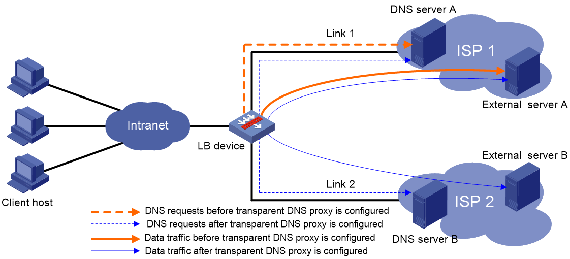
Workflow
The transparent DNS proxy is implemented by changing the destination IP address of DNS requests.
Figure 20 Transparent DNS proxy workflow
Table 2 Workflow description
|
Step |
Source IP address |
Destination IP address |
|
1. An intranet user on the client host sends a DNS request to the LB device. |
Host IP address |
IP address of DNS server A |
|
2. The LB device selects a DNS server to forward the DNS request according to the scheduling algorithm. |
N/A |
N/A |
|
3. The LB device changes the destination IP address of the DNS request as the IP address of the selected DNS server. |
Host IP address |
IP address of the selected DNS server |
|
4. The DNS server processes the DNS request and replies with a DNS response. |
IP address of the selected DNS server |
Host IP address |
|
5. The LB device changes the source IP address of the DNS response as the destination IP address of the DNS request. |
IP address of DNS server A |
Host IP address |
|
6. The intranet user accesses the external server according to the resolved IP address in the DNS response. |
Host IP address |
IP address of the external server |
|
7. The external server responds to the intranet user. |
IP address of the external server |
Host IP address |
Transparent DNS proxy on the LB device
The LB device distributes DNS requests to multiple links by changing the destination IP address of DNS requests.
As shown in Figure 21, the LB device contains the following elements:
· Transparent DNS proxy—The LB device performs transparent DNS proxy for a DNS request only when the port number of the DNS request matches the port number of the transparent DNS proxy.
· DNS server pool—A group of DNS servers.
· DNS server—Entity that processes DNS requests.
· Link—Physical link provided by an ISP.
· LB class—Classifies packets to implement load balancing based on packet type.
· LB action—Drops, forwards, or modifies packets.
· LB policy—Associates an LB class with an LB action. An LB policy can be referenced by the transparent DNS proxy.
Figure 21 Transparent DNS proxy on the LB device
If the destination IP address and port number of a DNS request match those of the transparent DNS proxy, the LB device processes the DNS request as follows:
1. The LB device finds the DNS server pool associated with the transparent DNS proxy.
2. The LB device selects a DNS server according to the scheduling algorithm configured for the DNS server pool.
3. The LB device uses the IP address of the selected DNS server as the destination IP address of the DNS request, and sends the request to the DNS server.
4. The DNS server receives and processes the DNS request, and replies with a DNS response.
The intranet user can now access the external server after receiving the DNS response.
Transparent DNS proxy tasks at a glance
To configure the transparent DNS proxy feature, perform the following tasks:
1. Configuring a transparent DNS proxy
2. Configuring a DNS server pool
5. (Optional.) Configuring an LB policy
6. (Optional.) Configuring a sticky group
7. (Optional.) Enabling load balancing logging
Configuring a transparent DNS proxy
By configuring a transparent DNS proxy, you can load balance DNS requests that match the transparent DNS proxy.
Restrictions and guidelines
If both the "Specifying the default DNS server pool" and "Specifying an LB policy" tasks are configured, packets are processed by the LB policy first. If the processing fails, the packets are processed by the default DNS server pool.
Transparent DNS proxy tasks at a glance
To configure a transparent DNS proxy, perform the following tasks:
1. Creating a transparent DNS proxy
2. Specifying an IP address and port number
3. Configuring a packet processing policy
Choose the following tasks as needed:
¡ Specifying the default DNS server pool
4. (Optional.) Specifying a VPN instance
5. (Optional.) Enabling the link protection feature
6. (Optional.) Configuring hot backup
7. Enabling the transparent DNS proxy
Creating a transparent DNS proxy
1. Enter system view.
system-view
2. Create a transparent DNS proxy and enter its view.
loadbalance dns-proxy dns-proxy-name type udp
Specifying an IP address and port number
Restrictions and guidelines
If server load balancing is configured, make sure the IP address and port number of the transparent DNS proxy are different than the virtual server of the UDP type.
As a best practice, configure an all-zero IP address for a transparent DNS proxy. In this case, all DNS requests are processed by the transparent DNS proxy.
Procedure
1. Enter system view.
system-view
2. Enter transparent DNS proxy view.
loadbalance dns-proxy dns-proxy-name
3. Specify an IP address for the transparent DNS proxy.
IPv4:
ip address ipv4-address [ mask-length | mask ]
IPv6:
ipv6 address ipv6-address [ prefix-length ]
By default, no IP address is specified for a transparent DNS proxy.
4. Specify the port number for the transparent DNS proxy.
port port-number
By default, the port number is 53 for a transparent DNS proxy.
Specifying the default DNS server pool
1. Enter system view.
system-view
2. Enter transparent DNS proxy view.
loadbalance dns-proxy dns-proxy-name
3. Specify the default DNS server pool for the transparent DNS proxy.
default dns-server-pool pool-name [ sticky sticky-name ]
By default, no default DNS server pool is specified for a transparent DNS proxy.
Specifying an LB policy
About this task
By referencing an LB policy, the transparent DNS proxy load balances matching DNS requests based on the packet contents. For more information about configuring an LB policy, see "Configuring an LB policy."
Procedure
1. Enter system view.
system-view
2. Enter transparent DNS proxy view.
loadbalance dns-proxy dns-proxy-name
3. Specify an LB policy for the transparent DNS proxy.
lb-policy policy-name
By default, a transparent DNS proxy does not reference any LB policies.
Specifying a VPN instance
1. Enter system view.
system-view
2. Enter transparent DNS proxy view.
loadbalance dns-proxy dns-proxy-name
3. Specify a VPN instance for the transparent DNS proxy.
vpn-instance vpn-instance-name
By default, a transparent DNS proxy belongs to the public network.
Enabling the link protection feature
About this task
This feature enables a transparent DNS proxy to select a DNS server based on the link bandwidth ratio. If the bandwidth ratio of a link is exceeded, the DNS server is not selected.
If the traffic volume on the link to a DNS server exceeds the maximum expected bandwidth multiplied by the bandwidth ratio, the DNS server is busy and will not be selected. If the traffic volume drops below the maximum expected bandwidth multiplied by the bandwidth recovery ratio, the DNS server participates in scheduling again. For more information about setting the bandwidth ratio, see "Setting the bandwidth ratio and maximum expected bandwidth."
Procedure
1. Enter system view.
system-view
2. Enter transparent DNS proxy view.
loadbalance dns-proxy dns-proxy-name
3. Enable the link protection feature.
bandwidth busy-protection enable
By default, the link protection feature is disabled.
Configuring hot backup
About this task
To implement hot backup for two LB devices, you must enable synchronization for session extension information and sticky entries to avoid service interruption.
Restrictions and guidelines
For successful sticky entry synchronization, if you want to specify a sticky group, enable sticky entry synchronization before specifying a sticky group on both LB devices. You can specify a sticky group by using the sticky sticky-name option when specifying the default DNS server pool.
The following configuration changes will cause the device to delete existing sticky entries and generate new ones based on subsequent traffic:
· Disable sticky entry synchronization.
· Change the sticky entry synchronization type.
Procedure
1. Enter system view.
system-view
2. Enter transparent DNS proxy view.
loadbalance dns-proxy dns-proxy-name
3. Enable session extension information synchronization.
connection-sync enable
By default, session extension information synchronization is disabled.
4. Enable sticky entry synchronization.
sticky-sync enable
By default, sticky entry synchronization is disabled.
Enabling the transparent DNS proxy
About this task
After configuring a transparent DNS proxy, you must enable the transparent DNS proxy for it to work.
Procedure
1. Enter system view.
system-view
2. Enter transparent DNS proxy view.
loadbalance dns-proxy dns-proxy-name
3. Enable the transparent DNS proxy.
service enable
By default, a transparent DNS proxy is disabled.
Configuring a DNS server pool
By configuring a DNS server pool, you can perform centralized management on DNS servers that have similar functions.
Creating a DNS server pool
1. Enter system view.
system-view
2. Create a DNS server pool and enter its view.
loadbalance dns-server-pool pool-name
3. (Optional.) Configure a description for the DNS server pool.
description text
By default, no description is configured for a DNS server pool.
Adding and configuring a DNS server pool member
About this task
Perform this task to create a DNS server pool member or add an existing DNS server as a DNS server pool member in DNS server pool view. You can also specify a DNS server pool for a DNS server in DNS server view to achieve the same purpose (see "Creating a DNS server and specifying a DNS server pool").
After adding a DNS server pool member, you can configure the following parameters and features for the DNS server in the DNS server pool:
· Weight.
· Priority.
· Health monitoring.
The member-based scheduling algorithm selects the best DNS server based on these configurations.
Adding a DNS server pool member
1. Enter system view.
system-view
2. Enter DNS server pool view.
loadbalance dns-server-pool pool-name
3. Create and add a DNS server pool member and enter DNS server pool member view.
dns-server dns-server-name port port-number
If the DNS server already exists, the command adds the existing DNS server as a DNS server pool member.
4. (Optional.) Configure a description for the DNS server pool member.
description text
By default, no description is configured for the DNS server pool member.
Setting the weight and priority of the DNS server pool member
1. Enter system view.
system-view
2. Enter DNS server pool view.
loadbalance dns-server-pool pool-name
3. Enter DNS server pool member view.
dns-server dns-server-name port port-number
4. Set the weight of the DNS server pool member.
weight weight-value
The default setting is 100.
5. Set the priority of the DNS server pool member.
priority priority
The default setting is 4.
Configuring health monitoring for the DNS server pool member
1. Enter system view.
system-view
2. Enter DNS server pool view.
loadbalance dns-server-pool pool-name
3. Enter DNS server pool member view.
dns-server dns-server-name port port-number
4. Specify a health monitoring method for the DNS server pool member.
probe template-name
By default, no health monitoring method is specified for the DNS server pool member.
You can specify an NQA template for health monitoring. For information about NQA templates, see NQA configuration in Network Management and Monitoring Configuration Guide.
5. Specify the health monitoring success criteria for the DNS server pool member.
success-criteria { all | at-least min-number }
By default, health monitoring succeeds only when all the specified health monitoring methods succeed.
Configuring a scheduling algorithm for a DNS server pool
About this task
Perform this task to specify a scheduling algorithm for a DNS server pool and specify the number of DNS servers to participate in scheduling. The LB device calculates the DNS servers to process DNS requests based on the following scheduling algorithms:
· Source IP address hash algorithm—Hashes the source IP address of DNS requests and distributes DNS requests to different DNS servers according to the hash values. This hash algorithm ensures that DNS requests with the same source IP address are distributed to the same DNS server.
· Source IP address and port hash algorithm—Hashes the source IP address and port number of DNS requests and distributes DNS requests to different DNS servers according to the hash values. This hash algorithm ensures that DNS requests with the same source IP address and port number are distributed to the same DNS server.
· Destination IP address hash algorithm—Hashes the destination IP address of DNS requests and distributes DNS requests to different DNS servers according to the hash values. This hash algorithm ensures that DNS requests with the same destination IP address are distributed to the same DNS server.
· Random algorithm—Distributes DNS requests to DNS servers randomly.
· Weighted round-robin algorithm—Distributes DNS requests to DNS servers in a round-robin manner according to the weights of DNS servers. For example, you can assign weight values 2 and 1 to DNS server A and DNS server B, respectively. This algorithm distributes two DNS requests to DNS server A and then distributes one DNS request to DNS server B. This algorithm applies to scenarios where DNS servers have different performance and bear similar load for each session.
· Bandwidth algorithm—Distributes DNS requests to DNS servers according to the weights and remaining bandwidths of DNS servers. When the remaining bandwidths of two DNS servers are the same, this algorithm is equivalent to the round-robin algorithm. When the weights of two DNS servers are the same, this algorithm always distributes DNS requests to the DNS server that has larger remaining bandwidth.
· Maximum bandwidth algorithm—Distributes DNS requests always to an idle DNS server that has the largest remaining bandwidth.
Procedure
1. Enter system view.
system-view
2. Enter DNS server pool view.
loadbalance dns-server-pool pool-name
3. Specify a scheduling algorithm for the DNS server pool.
predictor hash address { destination | source | source-ip-port } [ mask mask-length ] [ prefix prefix-length ]
predictor { random | round-robin | { bandwidth | max-bandwidth } [ inbound | outbound ] }
By default, the scheduling algorithm for a DNS server pool is weighted round robin.
4. Specify the number of DNS servers to participate in scheduling.
selected-server min min-number max max-number
By default, the DNS servers with the highest priority participate in scheduling.
Configuring health monitoring
About this task
Perform this task to enable health monitoring to detect the availability of DNS servers in a DNS server pool.
Restrictions and guidelines
The health monitoring configuration in DNS server view takes precedence over the configuration in DNS server pool view.
You can specify an NQA template for health monitoring. For information about NQA templates, see NQA configuration in Network Management and Monitoring Configuration Guide.
Procedure
1. Enter system view.
system-view
2. Enter DNS server pool view.
loadbalance dns-server-pool pool-name
3. Specify a health monitoring method for the DNS server pool.
probe template-name
By default, no health monitoring method is specified for a DNS server pool.
4. Specify the health monitoring success criteria for the DNS server pool.
success-criteria { all | at-least min-number }
By default, health monitoring succeeds only when all the specified health monitoring methods succeed.
Configuring a DNS server
Perform this task to configure an entity on the LB device for processing DNS requests. DNS servers configured on the LB device correspond to DNS servers in ISP networks. A DNS server can belong to multiple DNS server pools. A DNS server pool can contain multiple DNS servers.
DNS server tasks at a glance
To configure a DNS server, perform the following tasks:
1. Creating a DNS server and specifying a DNS server pool
2. Configuring an IP address for a DNS server
Choose one of the following tasks:
¡ Specifying an IP address and port number
¡ Enabling the device to automatically obtain the IP address of a DNS server
4. Associating a link with a DNS server
5. (Optional.) Setting a weight and priority
6. (Optional.) Configuring health monitoring
Creating a DNS server and specifying a DNS server pool
1. Enter system view.
system-view
2. Create a DNS server and enter its view.
loadbalance dns-server dns-server-name
3. (Optional.) Configure a description for the DNS server.
description text
By default, no description is configured for a DNS server.
4. Specify a DNS server pool for the DNS server.
dns-server-pool pool-name
By default, a DNS server does not belong to any DNS server pool.
Specifying an IP address and port number
1. Enter system view.
system-view
2. Enter DNS server view.
loadbalance dns-server dns-server-name
3. Specify an IP address for the DNS server.
IPv4:
ip address ipv4-address
IPv6:
ipv6 address ipv6-address
By default, no IP address is specified for a DNS server.
4. Specify the port number for the DNS server.
port port-number
By default, the port number of a DNS server is 0. Packets use their own port numbers.
Specifying a VPN instance
1. Enter system view.
system-view
2. Enter DNS server view.
loadbalance dns-server dns-server-name
3. Specify a VPN instance for the DNS server.
vpn-instance vpn-instance-name
By default, a DNS server belongs to the public network.
Enabling the device to automatically obtain the IP address of a DNS server
About this task
In scenarios where IP addresses are obtained through PPPoE, an LB device can dynamically obtain the IP address of a DNS server.
Before configuring this task, you must specify the outgoing interface for the link associated with the DNS server. Otherwise, the IP address of the DNS server cannot be obtained.
Procedure
1. Enter system view.
system-view
2. Enter DNS server view.
loadbalance dns-server dns-server-name
3. Enable the device to automatically obtain the IP address of the DNS server.
auto-alloc address
By default, the device does not automatically obtain the IP address of a DNS server.
Associating a link with a DNS server
Restrictions and guidelines
A DNS server can be associated with only one link. A link can be associated with multiple DNS servers.
Procedure
1. Enter system view.
system-view
2. Enter DNS server view.
loadbalance dns-server dns-server-name
3. Associate a link with the DNS server.
link link-name
By default, no link is associated with a DNS server.
Setting a weight and priority
About this task
Perform this task to set a weight for the weighted round robin algorithm and bandwidth algorithm of a DNS server, and set the scheduling priority in the DNS server pool for the DNS server.
Procedure
1. Enter system view.
system-view
2. Enter DNS server view.
loadbalance dns-server dns-server-name
3. Set a weight for the DNS server.
weight weight-value
By default, the weight of a DNS server is 100.
4. Set a priority for the DNS server.
priority priority
By default, the priority of a DNS server is 4.
Configuring health monitoring
About this task
Perform this task to enable health monitoring to detect the availability of a DNS server.
Restrictions and guidelines
The health monitoring configuration in DNS server view takes precedence over the configuration in DNS server pool view.
Procedure
1. Enter system view.
system-view
2. Enter DNS server view.
loadbalance dns-server dns-server-name
3. Specify a health monitoring method for the DNS server.
probe template-name
By default, no health monitoring method is specified for a DNS server.
4. Specify the health monitoring success criteria for the DNS server.
success-criteria { all | at-least min-number }
By default, health monitoring succeeds only when all the specified health monitoring methods succeed.
Configuring a link
A link is a physical link provided by an ISP. You can guide traffic forwarding by specifying an outbound next hop for a link. You can enhance link performance by configuring the maximum bandwidth, health monitoring, bandwidth ratio, and maximum expected bandwidth.
Link tasks at a glance
To configure a link, perform the following tasks:
2. Specifying a next hop IP address or an outgoing interface
Choose one of the following tasks:
¡ Specifying an outbound next hop for a link
¡ Specifying an outgoing interface for a link
3. (Optional.) Specifying a VPN instance
4. (Optional.) Configuring the maximum bandwidth
5. (Optional.) Configuring health monitoring
6. (Optional.) Setting the bandwidth ratio and maximum expected bandwidth
Creating a link
1. Enter system view.
system-view
2. Create a link and enter link view.
loadbalance link link-name
3. (Optional.) Configure a description for the link.
description text
By default, no description is configured for a link.
Specifying an outbound next hop for a link
1. Enter system view.
system-view
2. Enter link view.
loadbalance link link-name
3. Specify an outbound next hop for the link.
IPv4:
router ip ipv4-address
IPv6:
router ipv6 ipv6-address
By default, no outbound next hop is specified for a link.
Specifying an outgoing interface for a link
About this task
In scenarios where IP addresses are obtained through PPPoE, an LB device can dynamically obtain the outbound next hop IP address through the specified outgoing interface.
Procedure
1. Enter system view.
system-view
2. Enter link view.
loadbalance link link-name
3. Specify an outgoing interface for the link.
router interface interface-type interface-number
By default, no outgoing interface is specified for a link.
Specifying a VPN instance
1. Enter system view.
system-view
2. Enter link view.
loadbalance link link-name
3. Specify a VPN instance for the link.
vpn-instance vpn-instance-name
By default, a link belongs to the public network.
Configuring the maximum bandwidth
1. Enter system view.
system-view
2. Enter link view.
loadbalance link link-name
3. Set the maximum bandwidth for the link.
rate-limit bandwidth [ inbound | outbound ] bandwidth-value kbps
By default, the maximum bandwidth for a link is not limited.
Configuring health monitoring
About this task
Perform this task to enable health monitoring to detect the availability of a link.
Procedure
1. Enter system view.
system-view
2. Enter link view.
loadbalance link link-name
3. Specify a health monitoring method for the link.
probe template-name
By default, no health monitoring method is specified for a link.
4. Specify the health monitoring success criteria for the link.
success-criteria { all | at-least min-number }
By default, the health monitoring succeeds only when all the specified health monitoring methods succeed.
Setting the bandwidth ratio and maximum expected bandwidth
About this task
When the traffic exceeds the maximum expected bandwidth multiplied by the bandwidth ratio of a link, new traffic (traffic that does not match any sticky entries) is not distributed to the link. When the traffic drops below the maximum expected bandwidth multiplied by the bandwidth recovery ratio of the link, the link participates in scheduling again.
In addition to being used for link protection, the maximum expected bandwidth is used for remaining bandwidth calculation in the bandwidth algorithm and maximum bandwidth algorithm.
Procedure
1. Enter system view.
system-view
2. Enter link view.
loadbalance link link-name
3. Set the bandwidth ratio.
bandwidth [ inbound | outbound ] busy-rate busy-rate-number [ recovery recovery-rate-number ]
By default, the total bandwidth ratio is 70.
4. Set the maximum expected bandwidth.
max-bandwidth [ inbound | outbound ] bandwidth-value kbps
By default, the maximum expected bandwidth is not limited.
Configuring an LB class
An LB class classifies packets by comparing packets against specific rules. Matching packets are further processed by LB actions. You can create a maximum of 65535 rules for an LB class.
LB class tasks at a glance
To configure an LB class, perform the following tasks:
2. Creating a match rule
Choose the following tasks as needed:
¡ Creating a match rule that references an LB class
¡ Creating a source IP address match rule
¡ Creating a destination IP address match rule
¡ Creating a domain name match rule
Creating an LB class
1. Enter system view.
system-view
2. Create a DNS LB class, and enter LB class view.
loadbalance class class-name type dns [ match-all | match-any ]
When you create an LB class, you must specify the class type. You can enter an existing LB class view without specifying the class type. If you specify the class type when entering an existing LB class view, the class type must be the one specified when you create the LB class.
3. (Optional.) Configure a description for the LB class.
description text
By default, no description is configured for an LB class.
Creating a match rule that references an LB class
1. Enter system view.
system-view
2. Enter LB class view.
loadbalance class class-name
3. Create a match rule that references an LB class.
match [ match-id ] class class-name
Creating a source IP address match rule
1. Enter system view.
system-view
2. Enter LB class view.
loadbalance class class-name
3. Create a source IP address match rule.
match [ match-id ] source { ip address ipv4-address [ mask-length | mask ] | ipv6 address ipv6-address [ prefix-length ] }
Creating a destination IP address match rule
1. Enter system view.
system-view
2. Enter LB class view.
loadbalance class class-name
3. Create a destination IP address match rule.
match [ match-id ] destination { ip address ipv4-address [ mask-length | mask ] | ipv6 address ipv6-address [ prefix-length ] }
Creating an ACL match rule
Restrictions and guidelines
If the specified ACL does not exist, the ACL match rule does not take effect.
Procedure
1. Enter system view.
system-view
2. Enter LB class view.
loadbalance class class-name
3. Create an ACL match rule.
match [ match-id ] acl [ ipv6 ] { acl-number | name acl-name }
By default, an LB class does not have any match rules.
Creating a domain name match rule
1. Enter system view.
system-view
2. Enter LB class view.
loadbalance class class-name
3. Create a domain name match rule.
match [ match-id ] domain-name domain-name
Configuring an LB action
About LB actions
LB actions include the following modes:
· Forwarding mode—Determines whether and how to forward packets. If no forwarding action is specified, packets are dropped.
· Modification mode—Modifies packets. To prevent the LB device from dropping the modified packets, the modification action must be used together with a forwarding action.
If you create an LB action without specifying any of the previous action modes, packets are dropped.
Restrictions and guidelines
The following tasks are mutually exclusive:
· Configuring the forwarding mode
· Specifying a DNS server pool for guiding packet forwarding
· Skipping the current transparent DNS proxy
Configuring one task automatically cancels the other task that you have configured.
LB action tasks at a glance
To configure an LB action, perform the following tasks:
2. (Optional.) Configuring a forwarding LB action
¡ Configuring the forwarding mode
¡ Specifying a DNS server pool for guiding packet forwarding
¡ Skipping the current transparent DNS proxy
¡ Matching the next rule upon failure to find a DNS server
¡ (Optional.) Matching the next rule when all DNS servers are busy
3. (Optional.) Configuring a modification LB action
¡ Configuring the ToS field in IP packets sent to the DNS server
Creating an LB action
1. Enter system view.
system-view
2. Create a DNS LB action and enter LB action view.
loadbalance action action-name type dns
When you create an LB action, you must specify the action type. You can enter an existing LB action view without specifying the action type. If you specify the action type when entering an existing LB action view, the action type must be the one specified when you create the LB action.
3. (Optional.) Configure a description for the LB action.
description text
By default, no description is configured for an LB action.
Configuring a forwarding LB action
About this task
Three forwarding LB action types are available:
· Forward—Forwards matching packets.
· Specify a DNS server pool for guiding packet forwarding.
· Skip the current transparent DNS proxy—Skips the current transparent DNS proxy and match the next transparent DNS proxy or virtual server.
· Match the next rule upon failure to find a DNS server—If the device fails to find a DNS server according to the LB action, it matches the packet with the next rule in the LB policy.
· Match the next rule when all DNS servers are busy.
Configuring the forwarding mode
1. Enter system view.
system-view
2. Enter DNS LB action view.
loadbalance action action-name
3. Configure the forwarding mode.
forward all
By default, the forwarding mode is to discard packets.
This command does not apply to SIP virtual servers.
Specifying a DNS server pool for guiding packet forwarding
1. Enter system view.
system-view
2. Enter DNS LB action view.
loadbalance action action-name
3. Specify a DNS server pool for guiding packet forwarding.
dns-server-pool pool-name [ sticky sticky-name ]
By default, no DNS server pool is specified for guiding packet forwarding.
Skipping the current transparent DNS proxy
1. Enter system view.
system-view
2. Enter DNS LB action view.
loadbalance action action-name
3. Skip the current transparent DNS proxy.
skip current-dns-proxy
By default, the forwarding mode is to discard packets.
Matching the next rule upon failure to find a DNS server
1. Enter system view.
system-view
2. Enter DNS LB action view.
loadbalance action action-name
3. Match the next rule upon failure to find a DNS server.
fallback-action continue
By default, the next rule is not matched (packets are dropped) when no DNS servers are available for an LB action.
Matching the next rule when all DNS servers are busy
1. Enter system view.
system-view
2. Enter LB action view.
loadbalance action action-name
3. Match the next rule when all DNS servers are busy.
busy-action continue
By default, the device assigns DNS requests to DNS servers regardless of whether they are busy.
Configuring the ToS field in IP packets sent to the DNS server
1. Enter system view.
system-view
2. Enter DNS LB action view.
loadbalance action action-name
3. Configure the ToS field in IP packets sent to the DNS server.
set ip tos tos-number
By default, the ToS field in IP packets sent to the DNS server is not changed.
Configuring an LB policy
LB policy tasks at a glance
To configure an LB policy, perform the following tasks:
3. Specifying the default LB action
Creating an LB policy
1. Enter system view.
system-view
2. Create a DNS LB policy and enter LB action view.
loadbalance policy policy-name type dns
When you create an LB policy, you must specify the policy type. You can enter an existing LB policy view without specifying the policy type. If you specify the policy type when entering an existing LB policy view, the policy type must be the one specified when you create the LB policy.
3. (Optional.) Configure a description for the LB policy.
description text
By default, no description is configured for an LB policy.
Specifying an LB action
Restrictions and guidelines
A DNS LB policy can reference only DNS LB classes and DNS LB actions.
Procedure
1. Enter system view.
system-view
2. Enter DNS LB policy view.
loadbalance policy policy-name
3. Specify an LB action for an LB class.
class class-name [ insert-before before-class-name | insert-after [ after-class-name ] ] action action-name
By default, no LB action is specified for an LB class.
Specifying the default LB action
Restrictions and guidelines
The default LB action takes effect on packets that do not match any LB classes.
A DNS LB policy can reference only a DNS LB action as the default LB action.
Procedure
1. Enter system view.
system-view
2. Enter DNS LB policy view.
loadbalance policy policy-name
3. Specify the default LB action.
default-class action action-name
By default, no default LB action is specified.
Configuring a sticky group
A sticky group uses a sticky method to distribute similar sessions to the same DNS server according to sticky entries. The sticky method applies to the first packet of a session. Other packets of the session are distributed to the same DNS server.
Sticky group tasks at a glance
To configure a sticky group, perform the following tasks:
2. Configuring the IP sticky method
3. (Optional.) Configuring the timeout time for sticky entries
Creating a sticky group
1. Enter system view.
system-view
2. Create an address- and port-type sticky group and enter sticky group view.
sticky-group group-name type address-port
When you create a sticky group, you must specify the group type. You can enter an existing sticky group view without specifying the group type. If you specify the group type when entering an existing sticky group view, the group type must be the one specified when you create the sticky group.
3. (Optional.) Configure a description for the sticky group.
description text
By default, no description is configured for a sticky group.
Configuring the IP sticky method
1. Enter system view.
system-view
2. Enter sticky group view.
sticky-group group-name
3. Configure the IP sticky method.
IPv4:
ip [ port ] { both | destination | source } [ mask mask-length ]
IPv6:
ipv6 [ port ] { both | destination | source } [ prefix prefix-length ]
By default, no IP sticky method is configured.
Configuring the timeout time for sticky entries
1. Enter system view.
system-view
2. Enter sticky group view.
sticky-group group-name
3. Configure the timeout time for sticky entries.
timeout timeout-value
By default, the timeout time for sticky entries is 60 seconds.
Enabling load balancing logging
About load balancing logging
For security auditing purposes, enable load balancing logging to record load balancing information. Load balancing logging includes NAT logging and link busy state logging.
NAT logging records NAT session information, including IP address and port translation information and access information.
Link busy state logging records busy states for all links.
Enabling load balancing NAT logging
1. Enter system view.
system-view
2. Enable load balancing NAT logging.
loadbalance log enable nat
By default, load balancing NAT logging is disabled.
Enabling load balancing link busy state logging
1. Enter system view.
system-view
2. Enable load balancing link busy state logging.
loadbalance log enable bandwidth-busy
By default, load balancing link busy state logging is disabled.
Displaying and maintaining transparent DNS proxy
Execute display commands in any view and reset commands in user view.
|
Task |
Command |
|
Display DNS server pool information. |
display loadbalance dns-server-pool [ brief | name pool-name ] |
|
Display DNS server information. |
display loadbalance dns-server [ brief | name dns-server-name ] |
|
Display DNS server pool member information. |
display loadbalance dns-server dns-server-pool dns-server-pool-name [ name dns-server-name port port-number ] |
|
Display DNS server statistics. |
display loadbalance dns-server statistics [ name dns-server-name ] [ slot slot-number ] |
|
Display DNS server pool member statistics. |
display loadbalance dns-server statistics dns-server-pool dns-server-pool-name [ name dns-server-name port port-number ] [ slot slot-number ] |
|
Display transparent DNS proxy information. |
display loadbalance dns-proxy [ brief | name dns-proxy-name ] |
|
Display transparent DNS proxy statistics. |
display loadbalance dns-proxy statistics [ name dns-proxy-name ] [ slot slot-number ] |
|
Display link information. |
display loadbalance link [ brief | name link-name ] |
|
Display link statistics. |
display loadbalance link statistics [ name link-name ] [ slot slot-number ] |
|
Display LB class information. |
display loadbalance class [ name class-name ] |
|
Display LB action information. |
display loadbalance action [ name action-name ] |
|
Display LB policy information. |
display loadbalance policy [ name policy-name ] |
|
Display sticky entry information for transparent DNS proxies. |
display sticky dns-proxy [ dns-proxy-name dns-proxy-name ] [ class { class-name | default-class } | client-addr { ipv4-address | ipv6-address } | dns-server-addr { ipv4-address | ipv6-address } | dns-server-pool pool-name | dns-server-port port-number | key sticky-key ] * [ brief ] display sticky dns-proxy [ dns-proxy-name dns-proxy-name ] [ class { class-name | default-class } | client-addr { ipv4-address | ipv6-address } | dns-server-addr { ipv4-address | ipv6-address } | dns-server-pool pool-name | dns-server-port port-number | key sticky-key ] * [ brief ] [ slot slot-number ] |
|
Display sticky entry information for transparent DNS proxies. |
display sticky dns-proxy [ dns-proxy-name ] [ class class-name | default-class | default-dns-server-pool ] [ slot slot-number ] |
|
Display sticky group information. |
display sticky-group [ name group-name ] |
|
Display LB hot backup statistics. |
display loadbalance hot-backup statistics [ slot slot-number ] |
|
Clear DNS server statistics. |
reset loadbalance dns-server statistics [ dns-server-name ] |
|
Clear DNS server pool member statistics. |
reset loadbalance dns-server statistics dns-server-pool dns-server-pool-name [ name dns-server-name port port-number ] |
|
Clear transparent DNS proxy statistics. |
reset loadbalance dns-proxy statistics [ dns-proxy-name ] |
|
Clear link statistics. |
reset loadbalance link statistics [ link-name ] |
|
Clear LB hot backup statistics. |
reset loadbalance hot-backup statistics |
|
Clear sticky entry information for transparent DNS proxies. |
reset sticky dns-proxy [ dns-proxy-name dns-proxy-name ] [ class { class-name | default-class } | client-addr { ipv4-address | ipv6-address } | dns-server-addr { ipv4-address | ipv6-address } | dns-server-pool pool-name | dns-server-port port-number | key sticky-key ] * reset sticky dns-proxy [ dns-proxy-name dns-proxy-name ] [ class { class-name | default-class } | client-addr { ipv4-address | ipv6-address } | dns-server-addr { ipv4-address | ipv6-address } | dns-server-pool pool-name | dns-server-port port-number | key sticky-key ] * [ slot slot-number ] |
Transparent DNS proxy configuration examples
Example: Configuring transparent DNS proxy
Network configuration
In Figure 22, ISP 1 and ISP 2 provide two links with the same bandwidth: Link 1 and Link 2. The IP address of the DNS server of ISP 1 is 10.1.2.100. The IP address of the DNS server of ISP 2 is 20.1.2.100. Intranet users use domain name www.abc.com to access Web server A and Web server B.
Configure a transparent DNS proxy on the device to evenly distribute user traffic to Link 1 and Link 2.
Procedure
1. Assign IP addresses to interfaces:
# Assign an IP address to interface GigabitEthernet 1/0/1.
<Device> system-view
[Device] interface gigabitethernet 1/0/1
[Device-GigabitEthernet1/0/1] ip address 192.168.1.100 255.255.255.0
[Device-GigabitEthernet1/0/1] quit
# Assign IP addresses to other interfaces in the same way. (Details not shown.)
2. Add interfaces to security zones.
[Device] security-zone name trust
[Device-security-zone-Trust] import interface gigabitethernet 1/0/1
[Device-security-zone-Trust] quit
[Device] security-zone name untrust
[Device-security-zone-Untrust] import interface gigabitethernet 1/0/2
[Device-security-zone-Untrust] import interface gigabitethernet 1/0/3
[Device-security-zone-Untrust] quit
3. Configure a security policy:
Configure rules to permit traffic from the Trust security zone to the Untrust security zone and traffic from the Local security zone to the Untrust security zone, so the users can access the server:
# Configure a rule named lbrule1 to allow the users to access the server.
[Device] security-policy ip
[Device-security-policy-ip] rule name lbrule1
[Device-security-policy-ip-1-lbrule1] source-zone trust
[Device-security-policy-ip-1-lbrule1] destination-zone untrust
[Device-security-policy-ip-1-lbrule1] source-ip-subnet 192.168.1.0 255.255.255.0
[Device-security-policy-ip-1-lbrule1] action pass
[Device-security-policy-ip-1-lbrule1] quit
# Configure a rule named lblocalout to allow the device to send probe packets to the next hop.
[Device-security-policy-ip] rule 2 name lblocalout
[Device-security-policy-ip-2-lblocalout] source-zone local
[Device-security-policy-ip-2-lblocalout] destination-zone untrust
[Device-security-policy-ip-2-lblocalout] destination-ip-subnet 10.1.1.0 255.255.255.0
[Device-security-policy-ip-2-lblocalout] destination-ip-subnet 20.1.1.0 255.255.255.0
[Device-security-policy-ip-2-lblocalout] action pass
[Device-security-policy-ip-2-lblocalout] quit
[Device-security-policy-ip] quit
4. Configure links:
# Create the link link1 with next hop address 10.1.1.2.
[Device] loadbalance link link1
[Device-lb-link-link1] router ip 10.1.1.2
[Device-lb-link-link1] quit
# Create the link link2 with next hop address 20.1.1.2.
[Device] loadbalance link link2
[Device-lb-link-link2] router ip 20.1.1.2
[Device-lb-link-link2] quit
5. Create a DNS server pool named dsp.
[Device] loadbalance dns-server-pool dsp
[Device-lb-dspool-dsp] quit
6. Configure DNS servers:
# Create a DNS server named ds1, configure its IP address as 10.1.2.100, assign it to DNS server pool dsp, and associate it with link link1.
[Device] loadbalance dns-server ds1
[Device-lb-ds-ds1] ip address 10.1.2.100
[Device-lb-ds-ds1] dns-server-pool dsp
[Device-lb-ds-ds1] link link1
[Device-lb-ds-ds1] quit
# Create a DNS server named ds2, configure its IP address as 20.1.2.100, assign it to DNS server pool dsp, and associate it with link link2.
[Device] loadbalance dns-server ds2
[Device-lb-ds-ds2] ip address 20.1.2.100
[Device-lb-ds-ds2] dns-server-pool dsp
[Device-lb-ds-ds2] link link2
[Device-lb-ds-ds2] quit
7. Configure a transparent DNS proxy:
# Create a UDP transparent DNS proxy named dns-proxy1, configure its IP address as 0.0.0.0, specify DNS server pool dsp as its default DNS server pool, and enable the transparent DNS proxy.
[Device] loadbalance dns-proxy dns-proxy1 type udp
[Device-lb-dp-udp-dp] ip address 0.0.0.0 0
[Device-lb-dp-udp-dp] default dns-server-pool dsp
[Device-lb-dp-udp-dp] service enable
[Device-lb-dp-udp-dp] quit
Verifying the configuration
# Display brief information about all DNS servers.
[Device] display loadbalance dns-server brief
DNS server Address Port Link State DNS server pool
ds1 10.1.2.100 0 link1 Active dsp
ds2 20.1.2.100 0 link2 Active dsp
# Display detailed information about all DNS server pools.
[Device] display loadbalance dns-server-pool
DNS server pool: dsp
Description:
Predictor: Round robin
Selected server: Disabled
Probe information:
Probe success criteria: All
Probe method:
Total DNS servers: 2
Active DNS servers: 2
DNS server list:
Name State Address port Link Weight Priority
ds1 Active 10.1.2.100 0 link1 100 4
ds2 Active 20.1.2.100 0 link2 100 4
# Display detailed information about all transparent DNS proxies.
[Device] display loadbalance dns-proxy
DNS proxy: dns-proxy1
Type: UDP
State: Active
Service state: Enabled
VPN instance:
IPv4 address: 1.1.1.0/24
IPv6 address: --
Port: 53
DNS server pool: dsp
Sticky:
LB policy:
Connection synchronization: Enabled
Sticky synchronization: Enabled
Bandwidth busy protection: Disabled
After you complete the previous configuration, the LB device can evenly distribute DNS requests to DNS server A and DNS server B. Then, intranet user traffic is evenly distributed to Link 1 and Link 2.
Configuring inbound link load balancing
About inbound link load balancing
Inbound link load balancing load balances traffic among the links from the external network to the internal network.
Application scenario
As shown in Figure 23, an enterprise provides services for extranet users through link 1 of ISP 1, link 2 of ISP 2, and link 3 of ISP 3. Inbound link load balancing evenly distributes traffic from extranet users to the internal server on multiple links. This feature can prevent link congestion and implement link switchover upon a link failure.
Workflow
Inbound link load balancing is implemented based on DNS resolution. The LB device acts as the authoritative DNS server to process DNS requests from extranet users and select the best link for extranet users. Figure 24 shows the inbound link load balancing workflow.
Figure 24 Inbound link load balancing workflow

Inbound link load balancing uses the following procedure:
1. The client host sends a DNS request to the local DNS server.
2. The local DNS server forwards the DNS request to the LB device.
3. Inbound link load balancing selects a virtual server on the optimal link by using scheduling algorithms, bandwidth limit, and health monitoring method.
4. The LB device sends the virtual server address to the local DNS server in a DNS response.
5. The local DNS server sends the virtual server address to the client host.
6. The client host initiates a connection request to the virtual server address. (The request is forwarded to the LB device.)
7. The LB device initiates a connection request to the internal server.
8. The internal server responds to the LB device.
9. The LB device responds to the client host.
Inbound link load balancing on the LB device
The LB device implements inbound link load balancing by receiving DNS requests and replying with DNS responses that carry IP addresses of virtual severs.
As shown in Figure 25, the LB device contains the following elements:
· DNS listener—Listens to DNS requests. When the destination IP address of a DNS request matches that of the DNS listener, the DNS request is processed by inbound link load balancing.
· DNS mapping—Associates a domain name with a virtual server pool. The LB device looks up the DNS mappings for the virtual server pool associated with a domain name.
· Link—Physical link provided by an ISP.
· Virtual server pool—Associates virtual servers with links. The availability of a virtual server and its associated link determines whether the virtual server participates in scheduling.
· Virtual server—A virtual entity for processing user services.
Figure 25 Inbound link load balancing on the LB device
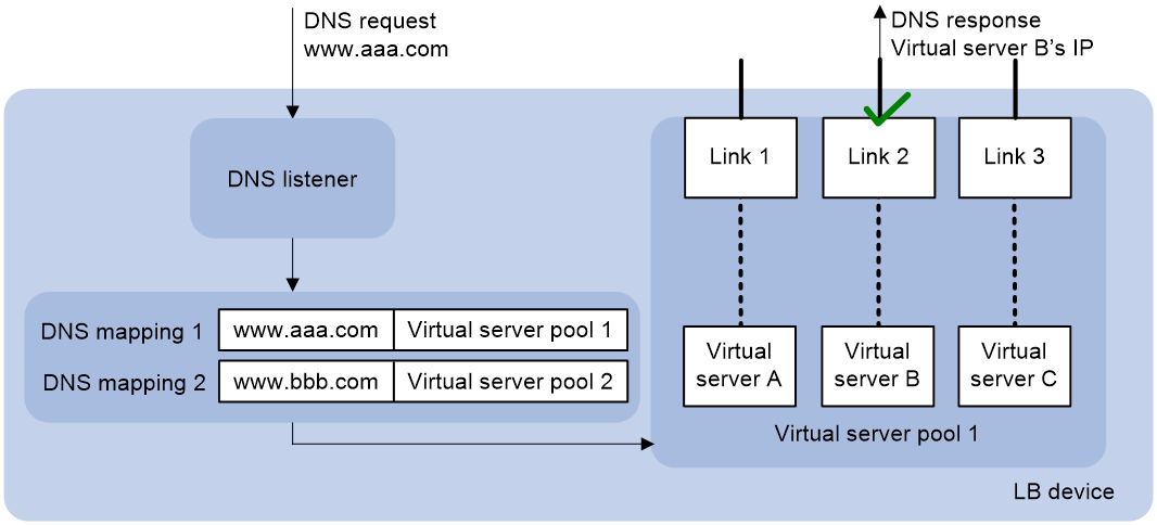
If the destination IP address of an incoming DNS request matches that of a DNS listener, the LB device processes the DNS request as follows:
1. The LB device looks up the DNS mappings for the virtual server pool associated with the domain name in the DNS request.
2. The LB device selects the virtual server associated with the best link according to the scheduling algorithm configured for the virtual server pool.
3. The LB device sends the IP address of the selected virtual server in a DNS response to the extranet user.
The extranet user uses the IP address of the virtual server as the destination IP address and accesses the internal server through the link associated with the virtual server.
Restrictions and guidelines: Inbound link load balancing configuration
You must contact the ISP to configure a delegating domain on the local DNS server to specify the LB device as the authoritative DNS server.
Inbound link load balancing tasks at a glance
To configure inbound link load balancing, perform the following tasks:
3. Configuring a virtual server
4. Configuring a virtual server pool
6. (Optional.) Configuring a DNS zone
¡ Configuring a DNS forward zone
¡ Configuring a DNS reverse zone
7. (Optional.) Configuring a topology
8. (Optional.) Configuring a region
9. (Optional.) Configuring ISP information
10. (Optional.) Enabling load balancing link busy state logging
11. (Optional.) Performing a load balancing test
12. (Optional.) Configuring DNS request parse failure settings
¡ Setting the maximum number of DNS request parse failures to be recorded
¡ Configuring the types of DNS request parse failures to be recorded
Configuring a DNS listener
DNS listener tasks at a glance
To configure a DNS listener, perform the following tasks:
2. Specifying an IP address and a port number for a DNS listener
3. (Optional.) Specifying a VPN instance
4. Enabling the DNS listening feature
5. (Optional.) Specifying the processing method for DNS mapping search failure
Creating a DNS listener
1. Enter system view.
system-view
2. Create a DNS listener and enter DNS listener view.
loadbalance dns-listener dns-listener-name
Specifying an IP address and a port number for a DNS listener
About this task
Perform this task to specify an IP address and a port number for the LB device to provide DNS services.
Procedure
1. Enter system view.
system-view
2. Enter DNS listener view.
loadbalance dns-listener dns-listener-name
3. Specify an IP address and a port number for the DNS listener.
IPv4:
ip address ipv4-address [ port port-number ]
IPv6:
ipv6 address ipv6-address [ port port-number ]
By default, a DNS listener does not have an IP address or port number.
Specifying a VPN instance
1. Enter system view.
system-view
2. Enter DNS listener view.
loadbalance dns-listener dns-listener-name
3. Specify a VPN instance for the DNS listener.
vpn-instance vpn-instance-name
By default, a DNS listener belongs to the public network.
Enabling the DNS listening feature
1. Enter system view.
system-view
2. Enter DNS listener view.
loadbalance dns-listener dns-listener-name
3. Enable the DNS listening feature.
service enable
By default, the DNS listening feature is disabled.
Specifying the processing method for DNS mapping search failure
1. Enter system view.
system-view
2. Enter DNS listener view.
loadbalance dns-listener dns-listener-name
3. Specify the processing method for DNS mapping search failure.
fallback { dns-proxy | no-response | reject }
By default, the processing method is reject.
Configuring a DNS mapping
By configuring a DNS mapping, you can associate a domain name with a virtual server pool.
DNS mapping tasks at a glance
To configure a DNS mapping, perform the following tasks:
2. Specifying a domain name for a DNS mapping
3. Specifying a virtual server pool for a DNS mapping
4. (Optional.) Setting the TTL for DNS records
5. Enabling the DNS mapping feature
Creating a DNS mapping
1. Enter system view.
system-view
2. Create a DNS mapping and enter DNS mapping view.
loadbalance dns-map dns-map-name
Specifying a domain name for a DNS mapping
Restrictions and guidelines
You can specify multiple domains names for a DNS mapping.
Procedure
1. Enter system view.
system-view
2. Enter DNS mapping view.
loadbalance dns-map dns-map-name
3. Specify a domain name for the DNS mapping.
domain-name domain-name
By default, a DNS mapping does not contain domain names.
Specifying a virtual server pool for a DNS mapping
1. Enter system view.
system-view
2. Enter DNS mapping view.
loadbalance dns-map dns-map-name
3. Specify a virtual server pool for the DNS mapping.
virtual-server-pool pool-name
By default, no virtual server pool is specified for a DNS mapping.
Setting the TTL for DNS records
About this task
Perform this task to set a proper TTL to cache DNS records for DNS responses.
· For the DNS client to get the updated DNS record when the LB policy or virtual server configuration changes, set a smaller TTL value, for example, 60 seconds.
· For stable, fast domain name resolution when the network is stable, set a larger TTL value, for example, 86400 seconds.
Procedure
1. Enter system view.
system-view
2. Enter DNS mapping view.
loadbalance dns-map dns-map-name
3. Set the TTL for DNS records.
ttl ttl-value
By default, the TTL for DNS records is 3600 seconds.
Enabling the DNS mapping feature
1. Enter system view.
system-view
2. Enter DNS mapping view.
loadbalance dns-map dns-map-name
3. Enable the DNS mapping feature.
slow-shutdown enable
By default, the DNS mapping feature is disabled.
Configuring a virtual server
About this task
Perform this task to specify the IP address and port number that the internal server uses to provide services. Configure inbound link load balancing virtual servers in the same way server load balancing virtual servers are configured. For more information about virtual server configuration, see "Configuring server load balancing."
Restrictions and guidelines
· To ensure correct operation of inbound link load balancing when server load balancing is also enabled, do not specify the virtual server's IP address as the DNS listener's IP address. For more information about specifying an IP address for a DNS listener, see "Specifying an IP address and a port number for a DNS listener."
· The virtual server's IPv4 address for inbound link load balancing must be a unicast address with a 32-bit mask length. The IPv4 address cannot be an all-zero address.
· The virtual server's IPv6 address for inbound link load balancing must be a unicast address with a 128-bit prefix length. The IPv6 address cannot be an all-zero address.
Configuring a virtual server pool
Perform this task to facilitate management of virtual servers with similar functions.
Virtual server pool tasks at a glance
To configure a virtual server pool, perform the following tasks:
1. Creating a virtual server pool
2. Adding a virtual server or virtual IP address. Choose the options to configure as needed:
3. (Optional.) Specifying scheduling algorithms for a virtual server pool
4. (Optional.) Enabling the link protection feature
Creating a virtual server pool
1. Enter system view.
system-view
2. Create a virtual server pool enter virtual server pool view.
loadbalance virtual-server-pool name
Adding a virtual server
1. Enter system view.
system-view
2. Enter virtual server pool view.
loadbalance virtual-server-pool name
3. Add a virtual server to the virtual server pool.
virtual-server virtual-server-name link link-name [ weight weight-name ]
By default, no virtual servers are added to a virtual server pool.
Adding a virtual IP address
1. Enter system view.
system-view
2. Enter virtual server pool view.
loadbalance virtual-server-pool name
3. Add a virtual IP address to the virtual server pool.
IPv4:
virtual-ip ipv4-address link link-name [ weight weight-value ]
IPv6:
virtual-ipv6 ipv6-address link link-name [ weight weight-value ]
By default, no virtual IP addresses are added to a virtual server pool.
Specifying scheduling algorithms for a virtual server pool
About this task
The device provides the following scheduling algorithms for a virtual server pool:
· Weighted least connection algorithm (least-connection)—Always assigns DNS requests to the virtual server with the fewest number of weighted active connections (the number of active connections divided by weight).
· Random algorithm (random)—Randomly assigns DNS requests to virtual servers.
· Round robin algorithm (round-robin)—Assigns DNS requests to virtual servers based on the weights of virtual servers. A higher weight indicates more DNS requests will be assigned.
· Static proximity algorithm (topology)—Assigns DNS requests to virtual servers based on static proximity entries.
· Dynamic proximity algorithm (proximity)—Assigns DNS requests to virtual servers based on dynamic proximity entries.
· Bandwidth algorithm (bandwidth)—Distributes DNS requests to DNS servers according to the weights and remaining bandwidth of DNS servers.
· Maximum bandwidth algorithm (max-bandwidth)—Distributes DNS requests always to an idle DNS server that has the largest remaining bandwidth.
· Source IP address hash algorithm (hash address source)—Hashes the source IP address of DNS requests and distributes DNS requests to different DNS servers according to the hash values.
· Source IP address and port hash algorithm (hash address source-ip-port)—Hashes the source IP address and port number of DNS requests and distributes DNS requests to different DNS servers according to the hash values.
· Destination IP address hash algorithm (hash address destination)—Hashes the destination IP address of DNS requests and distributes DNS requests to different DNS servers according to the hash values.
You can specify one preferred scheduling algorithm, one alternative scheduling algorithm, and one backup scheduling algorithm for a virtual server pool. If no virtual server can be selected by using the preferred scheduling algorithm, the alternative scheduling algorithm is used. If no virtual server can be selected by using the alternative scheduling algorithm, the backup scheduling algorithm is used.
Procedure
1. Enter system view.
system-view
2. Enter virtual server pool view.
loadbalance virtual-server-pool name
3. Specify a scheduling algorithm for the virtual server pool.
predictor { alternate | fallback | preferred } { least-connection | proximity | random | round-robin | topology | { bandwidth | max-bandwidth } [ inbound | outbound ] | hash address { source | source-ip-port | destination } [ mask mask-length | prefix prefix-length ] }
By default, the preferred scheduling algorithm for the virtual server pool is round robin. No alternative or backup scheduling algorithm is specified.
Enabling the link protection feature
About this task
This feature enables a virtual server pool to select a virtual server based on the link bandwidth ratio. If the bandwidth ratio of a link is exceeded, the virtual server is not selected. For more information about configuring the bandwidth ratio, see "Setting the bandwidth ratio and maximum expected bandwidth."
Procedure
1. Enter system view.
system-view
2. Enter virtual server pool view.
loadbalance virtual-server-pool name
3. Enable the link protection feature.
bandwidth busy-protection enable
By default, the link protection feature is disabled.
Configuring an LB link
Link availability is one of the factors that determines whether a virtual server can participate in scheduling. Link availability depends on health monitoring, maximum expected bandwidth, and bandwidth ratio.
LB link tasks at a glance
To configure an LB link, perform the following tasks:
2. Specifying the outbound next hop for the LB link
3. (Optional.) Configuring health monitoring
4. (Optional.) Setting the bandwidth ratio and maximum expected bandwidth
Creating an LB link
1. Enter system view.
system-view
2. Create an LB link and enter LB link view.
loadbalance link link-name
Specifying the outbound next hop for the LB link
About this task
The outbound next hop is the IP address of the peer device on the link. You can perform health monitoring and bandwidth limiting on a link specified by the outbound next hop.
Procedure
1. Enter system view.
system-view
2. Enter LB link view.
loadbalance link link-name
3. Specify the outbound next hop for the LB link.
router ip ipv4-address
By default, the outbound next hop is not specified for the LB link.
Configuring health monitoring
About this task
Perform this task to enable health monitoring to detect link quality and status and to ensure link availability. The health monitoring configuration uses NQA templates. For more information about NQA template configuration, see Network Management and Monitoring Configuration Guide.
Restrictions and guidelines
You can configure multiple health monitoring methods for an LB link.
Procedure
1. Enter system view.
system-view
2. Enter LB link view.
loadbalance link link-name
3. Specify a health monitoring method for the LB link.
probe template-name
By default, no health monitoring method is specified for an LB link.
4. Specify the health monitoring success criteria for the LB link.
success-criteria { all | at-least min-number }
By default, the health monitoring succeeds only when all the specified health monitoring methods succeed.
Setting the bandwidth ratio and maximum expected bandwidth
About this task
When the traffic exceeds the maximum expected bandwidth multiplied by the bandwidth ratio of a link, new traffic is not distributed to the link. When the traffic drops below the maximum expected bandwidth multiplied by the bandwidth recovery ratio of the link, the link participates in scheduling again.
In addition to being used for link protection, the maximum expected bandwidth is used for remaining bandwidth calculation in the bandwidth algorithm and maximum bandwidth algorithm.
Procedure
1. Enter system view.
system-view
2. Enter LB link view.
loadbalance link name
3. Set the bandwidth ratio.
bandwidth [ inbound | outbound ] busy-rate-number [ recovery recovery-rate-number ]
By default, the total bandwidth ratio is 70.
4. Set the maximum expected bandwidth.
max-bandwidth [ inbound | outbound ] bandwidth-value kbps
By default, the maximum expected bandwidth, maximum inbound expected bandwidth, and maximum outbound expected bandwidth are 0. The bandwidths are not limited.
Configuring a DNS forward zone
About DNS resource records
During DNS resolution, an LB device looks up the resource records configured in a DNS forward zone for the host name corresponding to the target domain name. DNS resource records are used by an LB device to resolve DNS requests and have the following types:
· Canonical name (CNAME)—Maps multiple aliases to one host name (server). For example, an enterprise intranet has a server with host name host.aaa.com. The server provides both Web service and mail service. You can configure two aliases (www.aaa.com and mail.aaa.com) in a CNAME resource record for this server. When a user requests Web service, the user accesses www.aaa.com. When a user requests mail service, the user accesses mail.aaa.com. Actually, the user accesses host.aaa.com in both cases.
· Mail exchanger (MX)—Specifies the mail server for a DNS forward zone.
· Name server (NS)—Specifies the authoritative DNS server for a DNS forward zone.
· Start of authority (SOA)—Specifies authoritative information about a DNS forward zone, including the primary DNS server and administrator mailbox.
· Service (SRV)—Specifies the services for a DNS forward zone and the servers that provide these services.
· Text (TXT)—Specifies a description for a DNS forward zone.
As shown in Figure 26, the LB device is configured with a DNS forward zone. After receiving a DNS request, the LB device first looks up the resource records in the DNS forward zone for the host name corresponding to the target domain name. Then the LB device looks up the DNS mappings for the IP address of the virtual server associated with the host name.
Figure 26 DNS forward zone workflow on the LB device
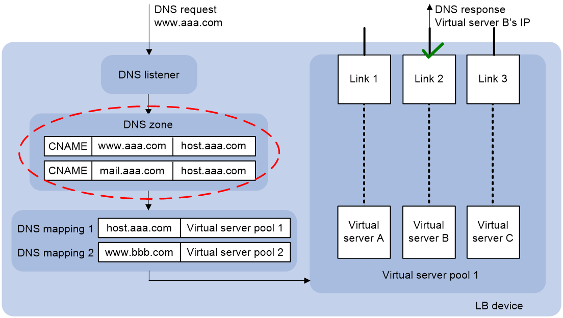
DNS forward zone tasks at a glance
To configure a DNS forward zone, perform the following tasks:
1. Creating a DNS forward zone
2. (Optional.) Configuring resource records
¡ Configuring a resource record of the specified type
This task allows you to configure CNAME, MX, NS, SRV, and TXT resource records.
¡ (Optional.) Configuring an SOA resource record
3. (Optional.) Setting the TTL for resource records
Creating a DNS forward zone
1. Enter system view.
system-view
2. Create a DNS forward zone and enter DNS forward zone view.
loadbalance zone domain-name
Configuring a resource record of the specified type
1. Enter system view.
system-view
2. Enter DNS forward zone view.
loadbalance zone domain-name
3. Configure a resource record of the specified type.
record { cname alias alias-name canonical canonical-name | mx [ host hostname ] exchanger exchanger-name preference preference | ns [ sub subname ] authority ns-name | srv [ service service-name ] host-offering-service hostname priority priority weight weight port port-number | txt [ sub subname ] describe-txt description } [ ttl ttl-value ]
By default, a DNS forward zone does not contain resource records.
Configuring an SOA resource record
1. Enter system view.
system-view
2. Enter DNS forward zone view.
loadbalance zone domain-name
3. Create an SOA resource record and enter SOA view.
soa
4. Configure the host name for the primary DNS server.
primary-nameserver host-name
By default, no host name is configured for the primary DNS server.
5. Specify the email address of the administrator.
responsible-mail mail-address
By default, the email address of the administrator is not specified.
6. Configure the serial number for the DNS forward zone.
serial number
By default, the serial number for a DNS forward zone is 1.
7. Set the refresh interval.
refresh refresh-interval
By default, the refresh interval is 3600 seconds.
8. Set the retry interval.
retry retry-interval
By default, the retry interval is 600 seconds.
9. Set the expiration time.
expire expire-time
By default, the expiration time is 86400 seconds.
10. Set the minimum TTL.
min-ttl ttl-value
By default, the minimum TTL is 3600 seconds.
Setting the TTL for resource records
1. Enter system view.
system-view
2. Enter DNS forward zone view.
loadbalance zone domain-name
3. Set the TTL for resource records.
ttl ttl-value
By default, the TTL for resource records is 3600 seconds.
Configuring a DNS reverse zone
About this task
The LB device performs reverse DNS resolution according to the DNS reverse zone configuration. Reverse DNS resolution searches for a domain name according to an IP address. The pointer record (PTR) resource records configured in a DNS reverse zone record mappings between domain names and IP addresses.
Reverse DNS resolution is used to address spam attacks by verifying the validity of the email sender. When a mail server receives an email from an external user, it sends a reverse DNS resolution request to the LB device. The LB device resolves the source IP address of the sender into a domain name according to PTR resource records and sends the domain name to the mail server. The mail server compares the received domain name with the actual domain name of the sender. If the two domain names match, the mail server accepts the email. If not, the mail server considers the email as a spam email and discards it.
Procedure
1. Enter system view.
system-view
2. Create a DNS reverse zone and enter DNS reverse zone view.
loadbalance reverse-zone { ip ipv4-address mask-length | ipv6 ipv6-address prefix-length }
3. Configure a PTR resource record.
record ptr { ip ipv4-address | ipv6 ipv6-address } domain-name [ ttl ttl-value ]
By default, a DNS reverse zone does not contain PTR resource records.
Configuring a topology
About this task
A topology associates the region where the local DNS server resides with the IP address of a virtual server.
When the static proximity algorithm (topology) is specified for the virtual server pool, you must configure a topology. For more information about specifying a scheduling algorithm for a virtual server pool, see "Adding a virtual IP address"
When a DNS request matches multiple topology records, the topology record with the highest priority is selected.
Procedure
1. Enter system view.
system-view
2. Configure a topology.
topology region region-name { ip ipv4-address { mask-length | mask } | ipv6 ipv6-address prefix-length } [ priority priority ]
Configuring a region
About this task
A region contains network segments corresponding to different ISPs.
Procedure
1. Enter system view.
system-view
2. Create a region and enter region view.
loadbalance region region-name
3. Add an ISP to the region.
isp isp-name
By default, a region does not contain any ISPs.
Configuring ISP information
Configure inbound link load balancing ISP information in the same way outbound link load balancing ISP information is configured. For more information about ISP information configuration, see "Configuring outbound link load balancing."
Enabling load balancing link busy state logging
About this task
Perform this task to record busy states for all links.
Procedure
1. Enter system view.
system-view
2. Enable load balancing link busy state logging.
loadbalance log enable bandwidth-busy
By default, load balancing link busy state logging is disabled.
Performing a load balancing test
About performing a load balancing test
Perform this task in any view to test the load balancing result.
Performing an IPv4 load balancing test
To perform an IPv4 load balancing test, execute the following command in any view:
loadbalance local-dns-server schedule-test ip [ vpn-instance vpn-instance-name ] destination destination-address [ destination-port destination-port ] source source-address source-port source-port type { { a | aaaa | cname | mx | ns | soa | srv | txt } domain domain-name | ptr ip address { ipv4-address | ipv6-address } } [ slot slot-number ]
Performing an IPv6 load balancing test
To perform an IPv6 load balancing test, execute the following command in any view:
loadbalance local-dns-server schedule-test ipv6 [ vpn-instance vpn-instance-name ] destination destination-address [ destination-port destination-port ] source source-address source-port source-port type { { a | aaaa | cname | mx | ns | soa | srv | txt } domain domain-name | ptr ip address ipv4-address } [ slot slot-number ]
Setting the maximum number of DNS request parse failures to be recorded
1. Enter system view.
system-view
2. Set the maximum number of DNS request parse failures that can be recorded.
loadbalance local-dns-server parse-fail-record max-number max-number
The default setting is 10000.
Configuring the types of DNS request parse failures to be recorded
1. Enter system view.
system-view
2. Configure the types of DNS request parse failures that can be recorded.
loadbalance local-dns-server parse-fail-record type { a | aaaa | all-disable | all-enable | cname | mx | ns | ptr | soa | srv | txt }
By default, all types of DNS request parse failures are recorded.
Displaying and maintaining inbound link load balancing
Execute display commands in any view and reset commands in user view.
|
Task |
Command |
|
Display DNS listener information. |
display loadbalance dns-listener [ name listener-name ] |
|
Display DNS listener statistics. |
display loadbalance dns-listener statistics [ name dns-listener-name ] [ slot slot-number ] |
|
Display DNS mapping information. |
display loadbalance dns-map [ name dns-map-name ] |
|
Display DNS mapping statistics. |
display loadbalance dns-map statistics [ name dns-map-name ] [ slot slot-number ] |
|
Display virtual server pool information. |
display loadbalance virtual-server-pool [ brief | name pool-name ] |
|
Display LB link information. |
display loadbalance link [ brief | name link-name ] |
|
Display DNS forward zone information. |
display loadbalance zone [ name domain-name ] |
|
Display DNS reverse zone information. |
display loadbalance reverse-zone { ip [ ipv4-address mask-length ] | ipv6 [ ipv6-address prefix-length ] } |
|
Display ISP information. |
display loadbalance isp [ ip ipv4-address | ipv6 ipv6-address | name isp-name ] |
|
Display DNS request parse failures. |
display loadbalance local-dns-server parse-fail-record [ type { a | aaaa | cname | mx | ns | soa | srv | txt } ] [ domain domain-name ] | ptr [ ip address { ipv4-address | ipv6-address } ] ] [ vpn-instance vpn-instance-name ] [ slot slot-number ] |
|
Clear DNS listener statistics. |
reset loadbalance dns-listener statistics [ dns-listener-name ] |
|
Clear DNS mapping statistics. |
reset loadbalance dns-map statistics [ dns-map-name ] |
|
Clear DNS request parse failures. |
reset loadbalance local-dns-server parse-fail-record |
Inbound link load balancing configuration examples
Example: Configuring inbound link load balancing
Network configuration
In Figure 27, ISP 1 and ISP 2 provide two links, Link 1 and Link 2, with the same router hop count, bandwidth, and cost. The internal server uses domain name l.abc.com to provide services. The actual host name of the internal server is www.abc.com.
Configure inbound link load balancing for the device to select an available link for traffic from the client host to the internal server when a link fails.
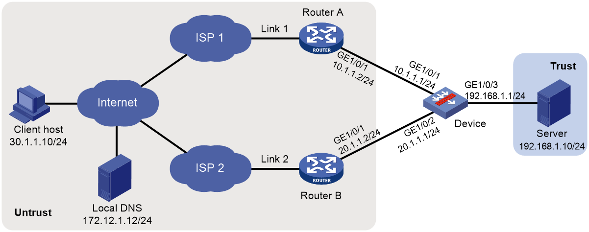
Procedure
1. Assign IP addresses to interfaces:
# Assign an IP address to interface GigabitEthernet 1/0/1.
<Device> system-view
[Device] interface gigabitethernet 1/0/1
[Device-GigabitEthernet1/0/1] ip address 10.1.1.1 255.255.255.0
[Device-GigabitEthernet1/0/1] quit
# Assign IP addresses to other interfaces in the same way. (Details not shown.)
2. Add interfaces to security zones.
[Device] security-zone name untrust
[Device-security-zone-Untrust] import interface gigabitethernet 1/0/1
[Device-security-zone-Untrust] import interface gigabitethernet 1/0/2
[Device-security-zone-Untrust] quit
[Device] security-zone name trust
[Device-security-zone-Trust] import interface gigabitethernet 1/0/2
[Device-security-zone-Trust] quit
3. Configure a security policy:
Configure rules to permit traffic from the Untrust security zone to the Trust security zone and traffic between the Untrust and Local security zones, so the users can access the server:
# Configure a rule named lbrule1 to allow the users to access the server.
[Device] security-policy ip
[Device-security-policy-ip] rule name lbrule1
[Device-security-policy-ip-1-lbrule1] source-zone untrust
[Device-security-policy-ip-1-lbrule1] destination-zone trust
[Device-security-policy-ip-1-lbrule1] destination-ip-subnet 192.168.1.0 255.255.255.0
[Device-security-policy-ip-1-lbrule1] action pass
[Device-security-policy-ip-1-lbrule1] quit
# Configure a rule named lblocalin to allow the users to access the DNS listener.
[Device-security-policy-ip] rule name lblocalin
[Device-security-policy-ip-2-lblocalout] source-zone untrust
[Device-security-policy-ip-2-lblocalout] destination-zone local
[Device-security-policy-ip-2-lblocalout] destination-ip-subnet 10.1.1.1 255.255.255.255
[Device-security-policy-ip-2-lblocalout] destination-ip-subnet 20.1.1.1 255.255.255.255
[Device-security-policy-ip-2-lblocalout] action pass
[Device-security-policy-ip-2-lblocalout] quit
[Device-security-policy-ip] quit
# Configure a rule named lblocalout to allow the device to send probe packets to the next hop.
[Device-security-policy-ip] rule name lblocalout
[Device-security-policy-ip-3-lblocalout] source-zone local
[Device-security-policy-ip-3-lblocalout] destination-zone untrust
[Device-security-policy-ip-3-lblocalout] destination-ip-subnet 10.1.1.0 255.255.255.0
[Device-security-policy-ip-3-lblocalout] destination-ip-subnet 20.1.1.0 255.255.255.0
[Device-security-policy-ip-3-lblocalout] action pass
[Device-security-policy-ip-3-lblocalout] quit
[Device-security-policy-ip] quit
4. Configure LB links:
# Create the ICMP-type NQA template t1.
[Device] nqa template icmp t1
[Device-nqatplt-icmp-t1] quit
# Create the LB link link1, and specify the outbound next hop as 10.1.1.2 and health monitoring method as t1 for the LB link.
[Device] loadbalance link link1
[Device-lb-link-link1] router ip 10.1.1.2
[Device-lb-link-link1] probe t1
[Device-lb-link-link1] quit
# Create the LB link link2, and specify the outbound next hop as 20.1.1.2 and health monitoring method as t1 for the LB link.
[Device] loadbalance link link2
[Device-lb-link-link2] router ip 20.1.1.2
[Device-lb-link-link2] probe t1
[Device-lb-link-link2] quit
5. Create the server farm sf.
[Device] server-farm sf
[Device-sfarm-sf] quit
6. Create the real server rs with the IPv4 address 192.168.1.10, and add it to the server farm sf.
[Device] real-server rs
[Device-rserver-rs] ip address 192.168.1.10
[Device-rserver-rs] server-farm sf
[Device-rserver-rs] quit
7. Configure virtual servers:
# Create the HTTP virtual server vs1 with the VSIP 10.1.1.3 and port number 80, specify its default master server farm sf, and enable the virtual server.
[Device] virtual-server vs1 type http
[Device-vs-http-vs1] virtual ip address 10.1.1.3
[Device-vs-http-vs1] port 80
[Device-vs-http-vs1] default server-farm sf
[Device-vs-http-vs1] service enable
[Device-vs-http-vs1] quit
# Create the HTTP virtual server vs2 with the VSIP 20.1.1.3 and port number 80, specify its default master server farm sf, and enable the virtual server.
[Device] virtual-server vs2 type http
[Device-vs-http-vs2] virtual ip address 20.1.1.3
[Device-vs-http-vs2] port 80
[Device-vs-http-vs2] default server-farm sf
[Device-vs-http-vs2] service enable
[Device-vs-http-vs2] quit
8. Create the virtual server pool vsp, and add the virtual servers vs1 and vs2 associated with the LB links link1 and link2 to the virtual server pool.
[Device] loadbalance virtual-server-pool vsp
[Device-lb-vspool-vsp] virtual-server vs1 link link1
[Device-lb-vspool-vsp] virtual-server vs2 link link2
9. Configure DNS listeners:
# Create the DNS listener dl1 with the IP address 10.1.1.1, and enable the DNS listener feature.
[Device] loadbalance dns-listener dl1
[Device-lb-dl-dl1] ip address 10.1.1.1
[Device-lb-dl-dl1] service enable
[Device-lb-dl-dl1] quit
# Create the DNS listener dl2 with the IP address 20.1.1.1, and enable the DNS listener feature.
[Device] loadbalance dns-listener dl2
[Device-lb-dl-dl2] ip address 20.1.1.1
[Device-lb-dl-dl2] service enable
[Device-lb-dl-dl2] quit
10. Create the DNS mapping dm, specify the domain name www.aaa.com and virtual server pool vsp for the DNS mapping, and enable the DNS mapping feature.
[Device] loadbalance dns-map dm
[Device-lb-dm-dm] domain-name www.aaa.com
[Device-lb-dm-dm] service enable
[Device-lb-dm-dm] virtual-server-pool vsp
[Device-lb-dm-dm] quit
11. Configure a DNS forward zone:
# Create a DNS forward zone with domain name aaa.com.
[Device] loadbalance zone aaa.com
# Configure a CNAME resource record by specifying alias l.aaa.com for host name www.aaa.com.
[Device-lb-zone-abc.com] record cname alias l.aaa.com. canonical www.aaa.com. ttl 600
[Device-lb-zone-abc.com] quit
Verifying the configuration
# Display information about all DNS listeners.
[Device] display loadbalance dns-listener
DNS listener name: dl1
Service state: Enabled
IPv4 address: 10.1.1.1
Port: 53
IPv6 address: --
IPv6 Port: 53
Fallback: Reject
VPN instance:
# Display information about all DNS mappings.
[Device] display loadbalance dns-map
DNS mapping name: dm
Service state: Enabled
TTL: 3600
Domain name list: www.aaa.com
Virtual server pool: vsp
# Display information about all DNS forward zones.
[Device] display loadbalance zone
Zone name: aaa.com
TTL: 3600s
SOA:
Record list:
Type TTL RDATA
CNAME 600s l.aaa.com. www.aaa.com.
# Display brief information about all virtual server pools.
[Device] display loadbalance virtual-server-pool brief
Predictor: RR - Round robin, RD - Random, LC - Least connection,
TOP - Topology, PRO - Proximity
BW - Bandwidth, MBW - Max bandwidth,
IBW - Inbound bandwidth, OBW - Outbound bandwidth,
MIBW - Max inbound bandwidth, MOBW - Max outbound bandwidth,
HASH(SIP) - Hash address source IP,
HASH(DIP) - Hash address destination IP,
HASH(SIP-PORT) - Hash address source IP-port
VSpool Pre Alt Fbk BWP Total Active
vsp RR LC Enabled 0 0
# Display detailed information about all virtual server pools.
[Device] display loadbalance virtual-server-pool
Virtual-server pool: local_pool
Predictor:
Preferred RR
Alternate --
Fallback --
Bandwidth busy-protection: Disabled
Total virtual servers: 2
Active virtual servers: 2
Virtual server list:
Name State Address Port Weight Link
vs1 Active 10.1.1.3 80 100 link1
vs2 Active 20.1.1.3 80 100 link2
# Display brief information about all real servers.
[Device] display real-server brief
Real server Address Port State VPN instance Server farm
rs 192.168.1.10 0 Active sf
# Display brief information about all LB links.
[Device] display loadbalance link brief
link Router IP State VPN instance Link group
link1 10.1.1.2 Active
link2 20.1.1.2 Probe-failed
# Display detailed information about all server farms.
[Device] display server-farm
Server farm: sf
Description:
Predictor: Round robin
Proximity: Enabled
NAT: Enabled
SNAT pool:
Failed action: Keep
Active threshold: Disabled
Slow-online: Disabled
Probe information:
Probe success criteria: All
Probe method:
t1
Selected server: Disabled
Probe information:
Probe success criteria: All
Probe method:
t1
Total real server: 1
Active real server: 1
Real server list:
Name State VPN instance Address Port Weight Priority
rs Active 192.168.1.10 0 100 4
# Display brief information about all virtual servers.
[Device] display virtual-server brief
Virtual server State Type VPN instance Virtual address Port
vs1 Active HTTP 10.1.1.3 80
vs2 Active HTTP 20.1.1.3 80
After you complete the previous configuration, domain name l.aaa.com can be resolved into 10.1.1.1 or 20.1.1.1. The client host can access the internal server through Link 1 or Link 2.
