- Table of Contents
- Related Documents
-
| Title | Size | Download |
|---|---|---|
| 01-Hardware Information and Specifications | 431.62 KB |
Contents
1 Product models and technical specifications
10/100/1000BASE-T autosensing Ethernet port
10/100/1000BASE-T autosensing Ethernet port LED (IE4300-12P-AC)
10/100/1000BASE-T autosensing Ethernet port LED (IE4300-12P-PWR)
1 Product models and technical specifications
Product models
This document is applicable to the following industrial switch models:
· IE4300-12P-AC
· IE4300-12P-PWR
Technical specifications
Table1-1 Technical specifications
|
Item |
IE4300-12P-AC |
IE4300-12P-PWR |
|
Dimensions (H × W × D) |
150 × 44 × 130 mm (5.91 × 1.73 × 5.12 in) |
150 × 44 × 130 mm (5.91 × 1.73 × 5.12 in) |
|
Weight |
≤ 1 kg (2.20 lb) |
≤ 1 kg (2.20 lb) |
|
Console port |
1 |
1 |
|
10/100/1000BASE-T autosensing Ethernet port |
8 |
8 (PoE capable) |
|
SFP port |
4 |
4 |
|
Alarm input (DI) |
The system detects exceptions of the connected device based on the input voltage changes on the alarm input connection. · State: ¡ 1: +13 to +30 V ¡ 0: –30 to + 3 V · Max. input current: 8 mA |
|
|
Alarm output (DO) |
Uses a relay for output, with a current carrying capacity of 1A @ 24 VDC The relay outputs alarms by opening or closing the contact. |
|
|
DIP switch |
Supported. For more information, see "DIP switches." |
|
|
Input voltage |
· Rated voltage range: 100 to 240 VAC @ 50 or 60 Hz · Max voltage range: 85 to 264 VAC @ 45 to 65 Hz |
· Rated voltage range: 54 to 57 VDC · Max voltage range: 54 to 57 VDC |
|
Max. PoE power per port |
N/A |
30 W |
|
Total PoE power |
N/A |
125 W |
|
Minimum power consumption |
7 W |
· Single DC input: 11 W · Dual DC inputs: 14 W |
|
Maximum power consumption (including PoE power consumption) |
12 W |
· Single DC input: 141 W · Dual DC inputs: 144 W |
|
Melting current of power supply fuse |
6.3 A/250 V |
8 A/125 V |
|
Cooling system |
Natural cooling without fan trays |
|
|
Operating altitude |
–60 to +5000 m (–196.85 to +16404.20 ft) The maximum acceptable temperature decreases by 0.33°C (32.59°F) for every 100 m (328.084 ft) increase in altitude from 0 m (0 ft). |
|
|
Operating humidity |
5% RH to 95% RH, noncondensing |
|
|
Ingress protection rating |
IP40 |
IP40 |
|
Pollution degree |
Degree 2. The switch is for indoor use only. |
|
|
Safety compliance |
UL 61010, UL 60950-1, EN 60950-1, IEC 60950-1, GB4943, IEC 62368-1, UL 62368-1, EN 62368-1 |
|
DIP switches
The switch provides DIP switches to enable or disable corresponding features.
Table1-2 DIP switch descriptions
|
Item |
Description |
|
Applicable switch models |
IE4300-12P-AC IE4300-12P-PWR |
|
DIP switch 1 |
Enables or disables flow control on the ports |
|
DIP switch 2 |
Enables or disables broadcast suppression on the ports |
|
DIP switch 3 |
Enables or disables link aggregation on ports 9 and 10 |
|
DIP switch 4 |
Enables or disables RRPP on ports 11 and 12 |
When DIP switch 1 is on, flow control is enabled on all ports. When DIP switch 1 is off, the status of the flow control feature depends on the configuration. For more information about flow control, see Ethernet interface configurations in the configuration guides for the switch.
When DIP switch 2 is on, broadcast suppression is enabled on all ports. When DIP switch 2 is off, the status of the broadcast suppression feature depends on the configuration. For more information about broadcast suppression, see Ethernet interface configurations in the configuration guides for the switch.
When DIP switch 3 is on, the system creates Layer 2 aggregation group 1 and adds the two uplink Ethernet ports to the group. When DIP switch 3 is off, the status of the link aggregation feature depends on the configuration. For more information about Layer 2 link aggregation, see Ethernet link aggregation configurations in the configuration guides for the switch.
When DIP switch 4 is on, RRPP is enabled. When DIP switch 4 is off, the status of the RRPP feature depends on the configuration. For more information, see RRPP configurations in the configuration guides for the switch.
2 Chassis views
IE4300-12P-AC
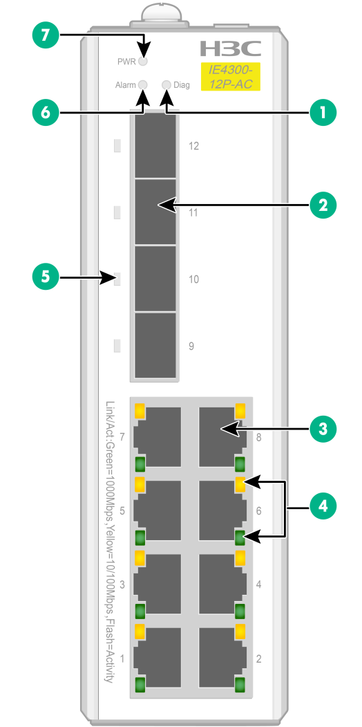
Figure2-1 Front panel
|
(1) Diag LED |
(2) SFP port |
|
(3) 10/100/1000BASE-T autosensing Ethernet port |
|
|
(4) 10/100/1000BASE-T autosensing Ethernet port LEDs |
|
|
(5) SFP port LED |
(6) Alarm LED |
|
(7) Power status LED (PWR) |
|
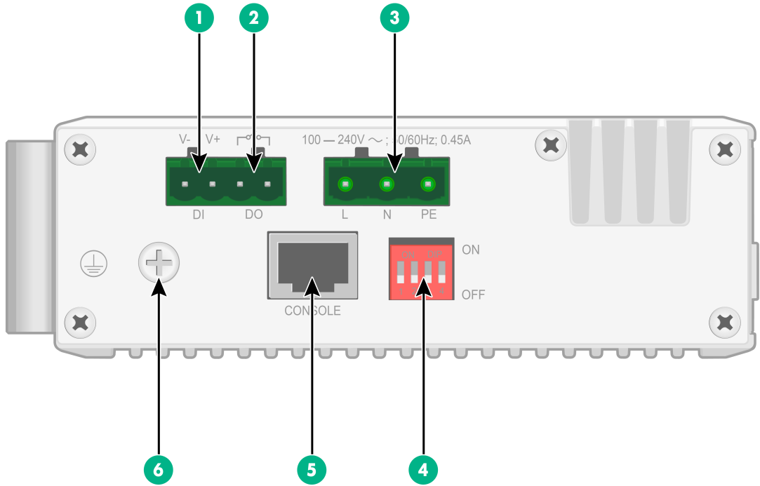
Figure2-2 Top panel
|
(2) Alarm output connection (DO) |
|
|
(3) AC power receptacle |
(4) DIP switch |
|
(5) Console port |
(6) Grounding screw |
|
|
CAUTION: The IE4300-12P-AC switch has a caution label on the top panel, indicating that no alarm cable and power cord are provided with the switch. Use only a copper alarm cable and power cord for the switch. |
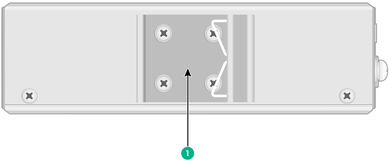
Figure2-3 Rear panel
|
(1) DIN rail mounting bracket |
IE4300-12P-PWR
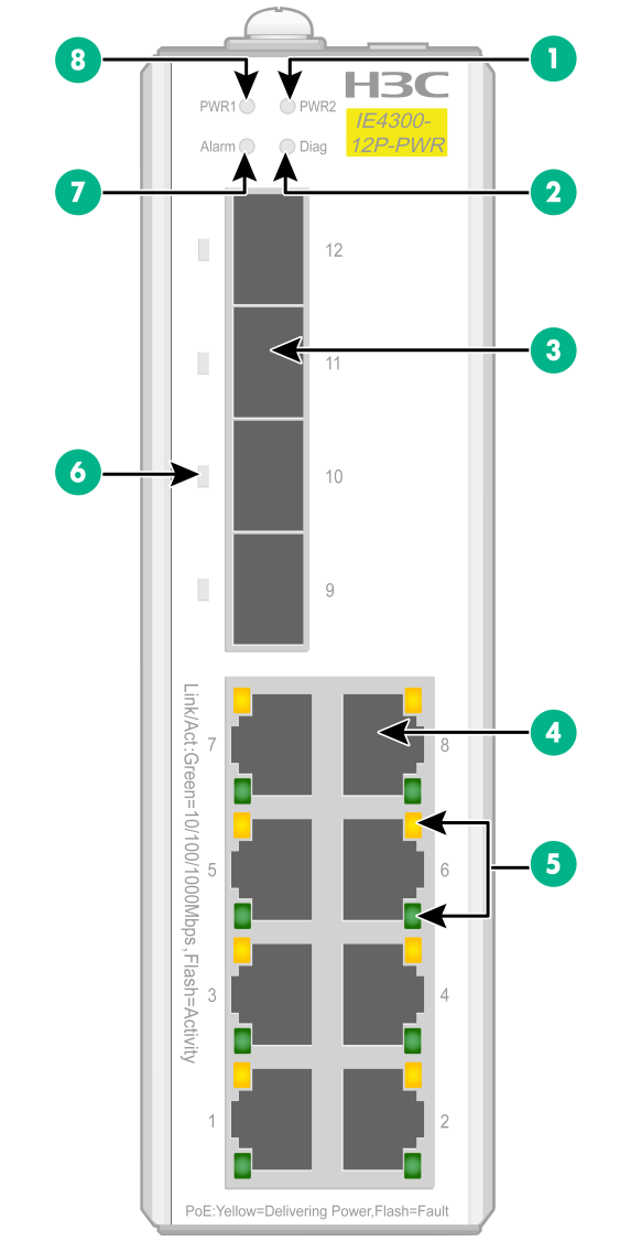
Figure2-4 Front panel
|
(1) PWR2 status LED |
(2) Diag LED |
|
(3) SFP port |
(4) 10/100/1000BASE-T autosensing Ethernet port |
|
(5) 10/100/1000BASE-T autosensing Ethernet port LEDs |
|
|
(6) SFP port LED |
|
|
(7) Alarm LED |
(8) PWR1 status LED |
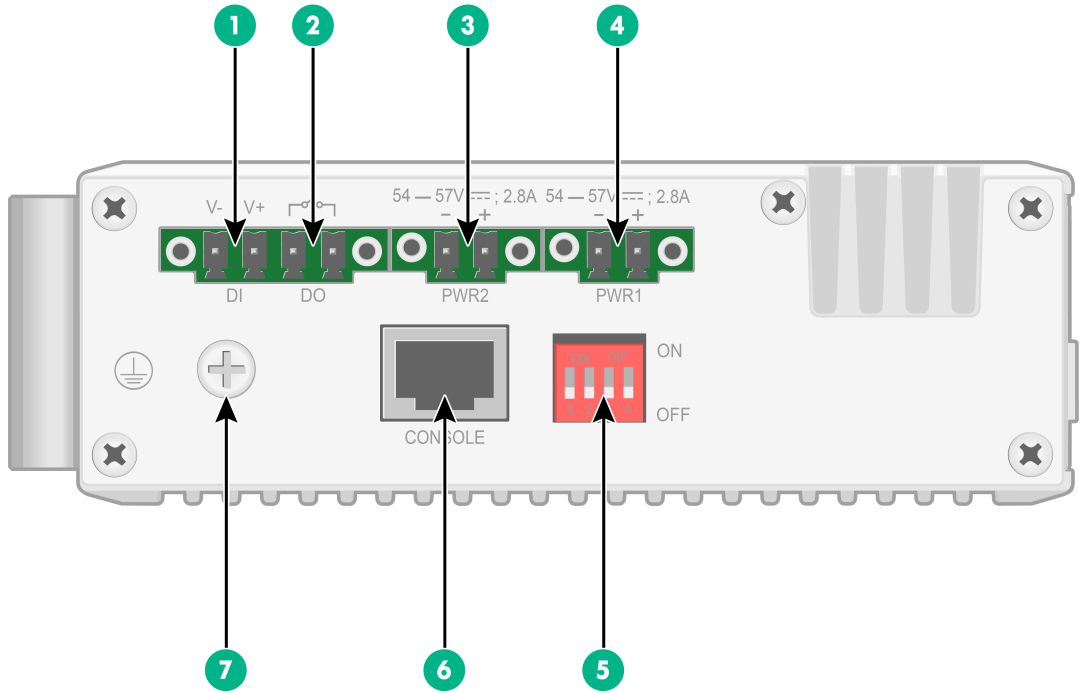
Figure2-5 Top panel
|
(1) Alarm input connection (DI) |
(2) Alarm output connection (DO) |
|
(3) DC power receptacle 2 (PWR2) |
(4) DC power receptacle 1 (PWR1) |
|
(5) DIP switch |
(6) Console port |
|
(7) Grounding screw |
|
|
|
CAUTION: The IE4300-12P-PWR switch has a caution label on the top panel, indicating that no alarm cable and power cord are provided with the switch. Use only a copper alarm cable and power cord for the switch. |
Figure2-6 Rear panel

|
(1) DIN rail mounting bracket |
3 Ports and LEDs
Ports
Console port
Table3-1 Console port specifications
|
Item |
Specification |
|
Connector type |
RJ-45 |
|
Compliant standard |
EIA/TIA-232 |
|
Transmission baud rate |
9600 bps (default) to 115200 bps |
|
Services |
· Provides connection to an ASCII terminal. · Provides connection to the serial port of a local terminal (PC for example) running a terminal emulation program. |
10/100/1000BASE-T autosensing Ethernet port
Table3-2 10/100/1000BASE-T autosensing Ethernet port specifications
|
Item |
Specification |
|
Connector type |
RJ-45 |
|
Rate and duplex mode |
· 10 Mbps, half/full-duplex · 100 Mbps, half/full-duplex · 1000 Mbps, full-duplex |
|
Auto MDI/MDI-X |
Supported |
|
Transmission medium and max transmission distance |
100 m (328.08 ft) over category-5 or above twisted pair cable |
|
Compliant standard |
IEEE 802.3i, 802.3u, 802.3ab |
SFP port
Table3-3 GE SFP transceiver modules and cables available for the SFP ports
|
GE SFP transceiver module and cable |
Central wavelength (nm) |
Connector |
Cable/Fiber type and diameter (µm) |
Modal bandwidth (MHz × km) |
Max transmission distance |
|
SFP copper transceiver module |
|||||
|
SFP-GE-T |
N/A |
RJ-45 |
Twisted pair cable |
N/A |
100 m (328.08 ft) |
|
SFP-GE-T-D |
N/A |
RJ-45 |
Twisted pair cable |
N/A |
100 m (328.08 ft) |
|
SFP fiber transceiver module |
|||||
|
SFP-GE-SX-MM850-A |
850 |
LC |
Multi-mode, 50/125 |
500 |
550 m (1804.46 ft) |
|
400 |
500 m (1640.42 ft) |
||||
|
Multi-mode, 62.5/125 |
200 |
275 m (902.23 ft) |
|||
|
160 |
220 m (721.78 ft) |
||||
|
SFP-GE-SX-MM850-D |
850 |
LC |
Multi-mode, 50/125 |
500 |
550 m (1804.46 ft) |
|
400 |
500 m (1640.42 ft) |
||||
|
Multi-mode, 62.5/125 |
200 |
275 m (902.23 ft) |
|||
|
160 |
220 m (721.78 ft) |
||||
|
SFP-GE-SX-MM850-S |
850 |
LC |
Multi-mode, 50/125 |
500 |
550 m (1804.46 ft) |
|
400 |
500 m (1640.42 ft) |
||||
|
Multi-mode, 62.5/125 |
200 |
275 m (902.23 ft) |
|||
|
160 |
220 m (721.78 ft) |
||||
|
SFP-GE-LX-SM1310-A |
1310 |
LC |
Single-mode, 9/125 |
N/A |
10 km (6.21 miles) |
|
Multi-mode, 50/125 |
500 or 400 |
550 m (1804.46 ft) |
|||
|
Multi-mode, 62.5/125 |
500 |
550 m (1804.46 ft) |
|||
|
SFP-GE-LX-SM1310-D |
1310 |
LC |
Single-mode, 9/125 |
N/A |
10 km (6.21 miles) |
|
SFP-GE-LX-SM1310-S |
1310 |
LC |
Single-mode, 9/125 |
N/A |
10 km (6.21 miles) |
|
SFP-GE-LX10-SM1310 |
1310 |
LC |
Single-mode, 9/125 |
N/A |
10 km (6.21 miles) |
|
SFP-GE-LH40-SM1310 |
1310 |
LC |
Single-mode, 9/125 |
N/A |
40 km (24.86 miles) |
|
SFP-GE-LH40-SM1310-D |
1310 |
LC |
Single-mode, 9/125 |
N/A |
40 km (24.86 miles) |
|
SFP-GE-LH40-SM1550 |
1550 |
LC |
Single-mode, 9/125 |
N/A |
40 km (24.86 miles) |
|
SFP-GE-LH80-SM1550 |
1550 |
LC |
Single-mode, 9/125 |
N/A |
80 km (49.71 miles) |
|
SFP-GE-LH80-SM1550-D |
1550 |
LC |
Single-mode, 9/125 |
N/A |
80 km (49.71 miles) |
|
SFP-GE-LH100-SM1550 |
1550 |
LC |
Single-mode, 9/125 |
N/A |
100 km (62.14 miles) |
|
SFP-GE-LX-SM1310-BIDI |
TX: 1310 RX: 1490 |
LC |
Single-mode, 9/125 |
N/A |
10 km (6.21 miles) |
|
SFP-GE-LX-SM1490-BIDI |
TX: 1490 RX: 1310 |
LC |
Single-mode, 9/125 |
N/A |
10 km (6.21 miles) |
|
SFP-GE-LH40-SM1310-BIDI |
TX: 1310 RX: 1550 |
LC |
Single-mode, 9/125 |
N/A |
40 km (24.86 miles) |
|
SFP-GE-LH40-SM1550-BIDI |
TX: 1550 RX: 1310 |
LC |
Single-mode, 9/125 |
N/A |
40 km (24.86 miles) |
|
SFP-GE-LH70-SM1490-BIDI |
TX: 1490 RX: 1550 |
LC |
Single-mode, 9/125 |
N/A |
70 mm (2.76 in) |
|
SFP-GE-LH70-SM1550-BIDI |
TX: 1550 RX: 1490 |
LC |
Single-mode, 9/125 |
N/A |
70 mm (2.76 in) |
|
SFP cable |
|||||
|
SFP-STACK-Kit |
N/A |
1.5 m (4.92 ft) |
|||
|
|
IMPORTANT: The SFP-GE-LX-SM1310-BIDI and SFP-GE-LX-SM1490-BIDI transceiver modules, the SFP-GE-LH40-SM1310-BIDI and SFP-GE-LH40-SM1550-BIDI transceiver modules, and the SFP-GE-LH70-SM1490-BIDI and SFP-GE-LH70-SM1550-BIDI transceiver modules must be used in pairs. For example, if one end uses an SFP-GE-LX-SM1310-BIDI transceiver module, the other end must use an SFP-GE-LX-SM1490-BIDI transceiver module. |
|
|
NOTE: · As a best practice, use H3C transceiver modules and cables for the switch. · The H3C transceiver modules and cables are subject to change over time. For the most recent list of H3C transceiver modules and cables, contact H3C marketing staff or technical support. · For the specifications of H3C transceiver modules and cables, see H3C Transceiver Modules User Guide. |
LEDs
Power status LED
An IE4300-12P-AC switch provides an AC power receptacle and uses a power status LED to indicate the power input status. Table3-4 provides the description of the power status LED on the IE4300-12P-AC switch.
An IE4300-12P-PWR switch provides two DC power receptacles and uses a power status LED for each receptacle to indicate the power input status. Table3-5 provides the description of the power status LEDs on the IE4300-12P-PWR switch.
Table3-4 Description of the power status LED on the IE4300-12P-AC switch
|
LED mark |
Status |
Description |
|
PWR |
Steady green |
Normal AC power input |
|
Off |
Abnormal or no AC power input |
Table3-5 Description of the power status LEDs on the IE4300-12P-PWR switch
|
LED mark |
Status |
Description |
|
PWR |
Steady green |
Normal DC power input |
|
Off |
Abnormal or no DC power input |
Alarm LED
The switch provides an alarm input connection on the top panel and can detect changes of the digital input voltage. When the digital input voltage exceeds the acceptable range, the system uses the alarm LED to indicate the exception.
Table3-6 Alarm LED description
|
LED mark |
Status |
Description |
|
Alarm |
Steady red |
A digital input exception has been detected. |
|
Off |
No exception has been detected. |
Diag LED
The switch provides a Diag LED on the front panel to indicate the system operating status.
Table3-7 Diag LED description
|
LED mark |
Status |
Description |
|
Diag |
Steady red |
The switch has failed the POST, or an alarm condition such as MAC chip overtemperature has occurred. |
|
Off |
The switch has passed the POST and is operating correctly. |
SFP port LED
Table3-8 SFP port LED description
|
Status |
Description |
|
Steady green |
A link is present on the port. |
|
Flashing green |
The port is sending or receiving data. |
|
Off |
No link is present on the port. |
10/100/1000BASE-T autosensing Ethernet port LED (IE4300-12P-AC)
Table3-9 10/100/1000BASE-T autosensing Ethernet port LED description
|
Green LED |
Yellow LED |
Description |
|
Steady on |
Off |
A link is present on the port and the port is operating at 1000 Mbps. |
|
Flashing |
Off |
The port is sending or receiving data at 1000 Mbps. |
|
Off |
Steady on |
A link is present on the port and the port is operating at 10/100 Mbps. |
|
Off |
Flashing |
The port is sending or receiving data at 10/100 Mbps. |
|
Off |
Off |
No link is present on the port or a link failure has occurred. |
|
|
NOTE: For the green and yellow LEDs for a 10/100/1000BASE-T autosensing Ethernet port, only one of them is on or flashing at a time. |
10/100/1000BASE-T autosensing Ethernet port LED (IE4300-12P-PWR)
An IE4300-12P-PWR switch provides a green and a yellow LED for each 10/100/1000BASE-T autosensing Ethernet port. The green and yellow LEDs indicate the data rate and PoE power supply status of the port, respectively.
Table3-10 10/100/1000BASE-T autosensing Ethernet port LED description
|
LED |
Status |
Description |
|
Green LED |
Steady on |
A link is present on the port and the port is operating at 10/100/1000 Mbps. |
|
Flashing |
The port is sending or receiving data at 10/100/1000 Mbps. |
|
|
Off |
No link is present on the port, or a link failure has occurred. |
|
|
Yellow LED |
Steady on |
A PD is connected to the port and the port is supplying power to the PD correctly. |
|
Flashing |
A PD is connected to the port but the port is not supplying power correctly to the PD. |
|
|
Off |
No PD is connected to the port, or PoE is not enabled on the port. |
