- Table of Contents
- Related Documents
-
| Title | Size | Download |
|---|---|---|
| 01-Text | 16.10 MB |
Installing an OS through the BIOS
Obtaining a storage controller driver
Installing a Red Hat/CentOS 6.x OS
Installing a Red Hat 7.x, Red Hat 8.x, CentOS 7.x, or CentOS 8.x OS
Installing an Oracle Linux 8.2 OS
Installing an OS and drivers through FIST
Setting up the FIST environment
Apply a server template for OS installation
Installing an OS and drivers through iFIST
Mounting an OS image and REPO file
Installing drivers on H3C servers
Installing a storage controller driver by using a .deb file (for Ubuntu OSs)
Installing a storage controller driver by using an .rpm file (for RedHat OSs)
Installing an FC HBA driver by using a .tar.gz file (for RedHat OSs)
Installing a GPU driver by using a .run file (for RedHat OSs)
Installing an FC HBA driver (for VMware OSs)
Updating storage controller firmware
The /dev/root directory not found during Linux OS installation
SUSE11SP4 installation failure
Failure to enter SUSE OS in Legacy mode
An error occurred during SLES12 OS installation
Failure to install an OS by using PXE
Failure to install a VMware OS when only mLOM adapters are installed
SUSE12SP2 OS installation takes a long time and the webpage is stuck after installation
An error occurred on an NVMe drive and the drive went offline after a managed hot plug
A blue screen occurred when the network adapter-10GE-2P-520F-B2-1 driver was being installed
Failed to install CASE0306 on an NVMe SSD drive
The system cannot be restored after the server is powered down unexpectedly
CAS E0306 OS installation failure
Overview
The information in this document might differ from your product if it contains custom configuration options or features.
Figures in this document are for illustration only and might differ from your product.
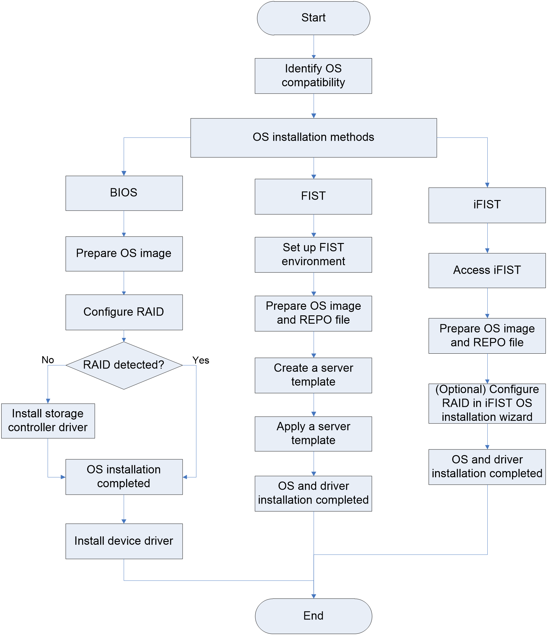
OS installation methods
The operating system (OS) installation methods vary by application scenario, as shown in Table 1.
Table 1 OS installation methods
|
Application scenario |
OS installation method |
Feature |
|
OS installation on a single server |
Most common OS installation method. You can monitor each installation phase and customize the settings. |
|
|
Simplifies OS installation and saves time. |
||
|
Bulk OS installation on multiple servers |
Installs OSs in bulk in a large-sized network. |
Applicable products
This document is applicable to the following products:
· H3C UniServer B5700 G3
· H3C UniServer B5700 G5
· H3C UniServer B5800 G3
· H3C UniServer B7800 G3
· H3C UniServer E3200 G3
· H3C UniServer R2700 G3
· H3C UniServer R2900 G3
· H3C UniServer R4100 G3
· H3C UniServer R4300 G3
· H3C UniServer R4300 G5
· H3C UniServer R4330 G5
· H3C UniServer R4400 G3
· H3C UniServer R4700 G3
· H3C UniServer R4700 G5
· H3C UniServer R4900 G3
· H3C UniServer R4900 G5
· H3C UniServer R4930 G5
· H3C UniServer R4950 G3
· H3C UniServer R4950 G5
· H3C UniServer R5300 G3
· H3C UniServer R5300 G5
· H3C UniServer R5500 G5
· H3C UniServer R6700 G3
· H3C UniServer R6900 G3
· H3C UniServer R6900 G5
· H3C UniServer R8900 G3
Verifying OS compatibility
Verify that the target OS is compatible with the server and its components, such as storage controllers and Ethernet adapters before OS installation. For more information, contact Technical Support.
Installing an OS through the BIOS
This section introduces OS installation in the BIOS Setup Utility through an optical disk drive, bootable USB disk, and virtual media.
Information on the BIOS setup utility is for illustration only and might differ from your products.
Preparing for installation
Preparing an OS image
Before installing an OS, obtain the OS image from the official website of the OS.
Obtaining a storage controller driver
To install an OS on a logical drive, you must also install the storage controller drivers. By default, an OS contains drivers for storage controllers of some models and the contained drivers vary by OS version.
As a best practice, install drivers separately or install the OS through FIST or iFIST.
To obtain storage controller drivers, access the official website of H3C at https://www.h3c.com/en/Support/Resource_Center/Software_Download/Servers/.
Logging in to the server
You can log in to the server locally or through a remote console.
Logging in to the server locally
You can connect a keyboard, monitor, and mouse to the server and then power on the server to manage it locally.
Launching a remote console through HDM
1. Obtain the management IP address and user account information of HDM.
For a rack server, the HDM shared network port obtains IP addresses through DHCP and the HDM dedicated network port uses IP address 192.168.1.2/24. For a blade server, you can log in to OM to view the management IP address.
By default, the username and password are admin and Password@_. Both the username and password are case-sensitive.
2. Make sure the PC meet the requirements in Table 2.
Table 2 Browser and resolution requirements
|
Item |
Description |
|
Browsers |
Google Chrome 48.0 (or higher) Mozilla Firefox 50.0 (or higher) Internet Explorer 11 (or higher) |
|
Resolution |
Minimum: 1366*768 Recommended: 1600*900 (or higher) |
3. Connect the server to the network.
¡ For a rack server, connect the network cable to the HDM shared network port or HDM dedicated network port.
¡ For a blade server, connect the network cable to the management port of OM.
Make sure the PC can reach the server.
4. Open a browser and access the HDM Web interface.
5. In the navigation pane, select Remote Control > Remote Console.
Figure 2 Entering remote console page
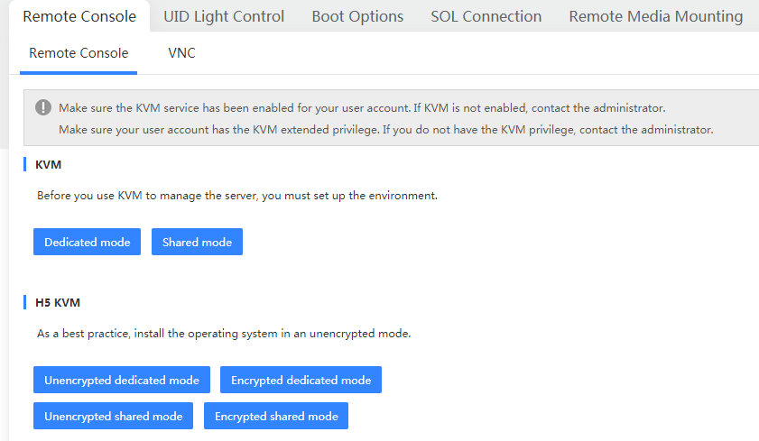
6. Launch a KVM or H5 KVM remote console as needed.
Launching a remote console through OM (only for blade servers)
1. Obtain the management IP address and user account information of OM.
The management port of OM obtains IP addresses through DHCP.
By default, the username and password are admin and Password@_. Both the username and password are case-sensitive.
2. Make sure the PC meet the requirements in Table 3.
Table 3 Browser and resolution requirements
|
Item |
Description |
|
Browsers |
Google Chrome 58.0 (or higher) |
|
Resolution |
1600*900 (or higher) |
3. Connect the PC to the management (MGMT) port on a minimum of one OM module, as shown in Figure 3.
Figure 3 Connecting the PC to both the active and standby OM modules
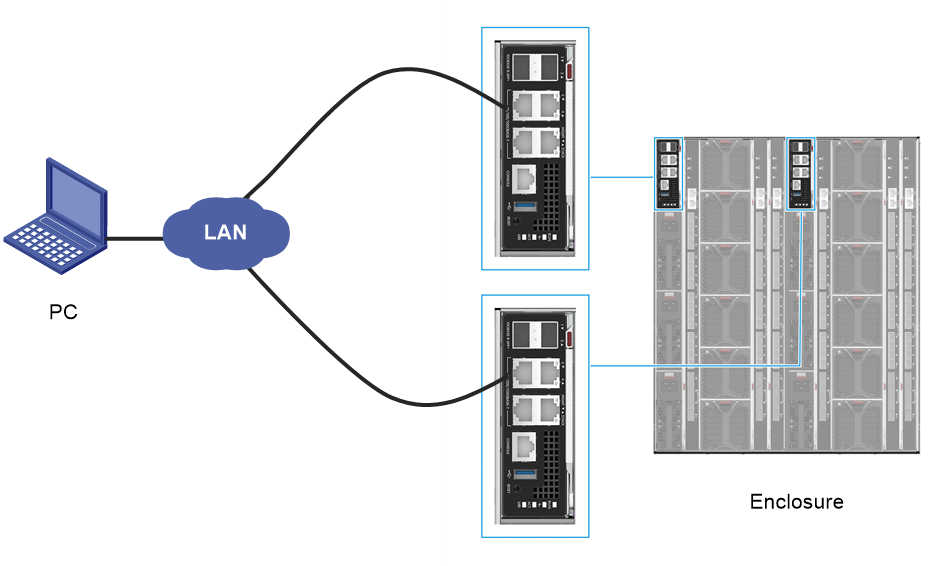
4. Configure IP settings on the PC for the PC to reach the OM modules.
5. Open the browser, enter the management IP address of OM in the format of https://OM_ip_address in the address bar, and then press Enter.
6. On the sign-in page, enter the username and password, and then click Login.
7. In the navigation pane, click Blade Servers, select the target server, and then click Remote Consoles.
8. On the Remote Consoles tab, click KVM or H5 KVM, as shown in Figure 4.
Figure 4 Launching a remote console

Connecting the OS image
Before installing an OS, connect the boot media that contain the OS image to the server.
· For local login, you can use an optical disk drive, bootable USB disk, or PXE server as the boot media.
· For remote console login, you can use an optical disk drive, bootable USB disk, PXE server, or virtual media (virtual disk, CD/DVD, or drive/USB) as the boot media. To install an OS on multiple servers in bulk, use a PXE server as the boot media.
Use Table 4 to determine the OS image preparation method based on the boot media.
|
Boot media |
Preparing for installation |
|
Insert the optical disk drive that contains the OS image into the optical drive. |
|
|
Bootable USB drive |
Insert the bootable USB disk that contains the OS image into the USB port. |
|
PXE |
1. Set up the PXE environment, including a TFTP server and a DHCP server. 2. Connect an Ethernet port on each server where the OS is to be installed to the PXE environment. For more information about how to set up the PXE environment, see the PXE environment setup guide. 3. Upload the OS image to the TFTP server. 4. Enable PXE (enabled by default) on the servers where the OS is to be installed. For more information, see "Enabling PXE." |
|
Virtual media |
Mount the OS image through HDM. For more information, see "Mounting an OS image through a remote console." |
Enabling PXE
PXE is enabled by default and cannot be disabled if the BIOS boot mode is Legacy. This section describes how to enable PXE in UEFI boot mode. For more information about BIOS boot modes, see "Setting the BIOS boot mode."
To enable PXE:
1. Enter the BIOS Setup Utility.
2. Click the Advanced tab, select Network Stack Configuration, and then press Enter.
3. Set Network Stack, IPv4 PXE Support, and IPv6 PXE Support to Enabled (Enabled by default).
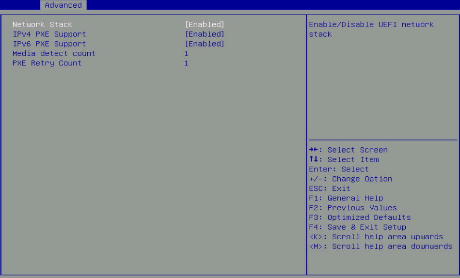
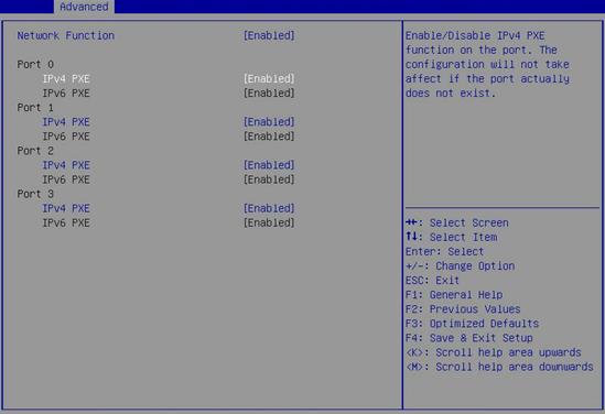
4. Access the Advanced > Network PXE Control screen. Then, enable PXE on each port (Enabled by default).
Figure 6 Enabling PXE on network ports
5. Press F4 to save the configuration and reboot the server.
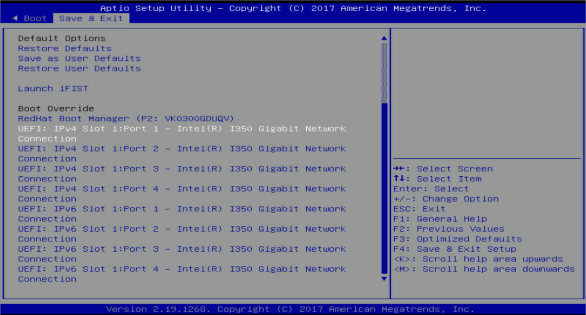
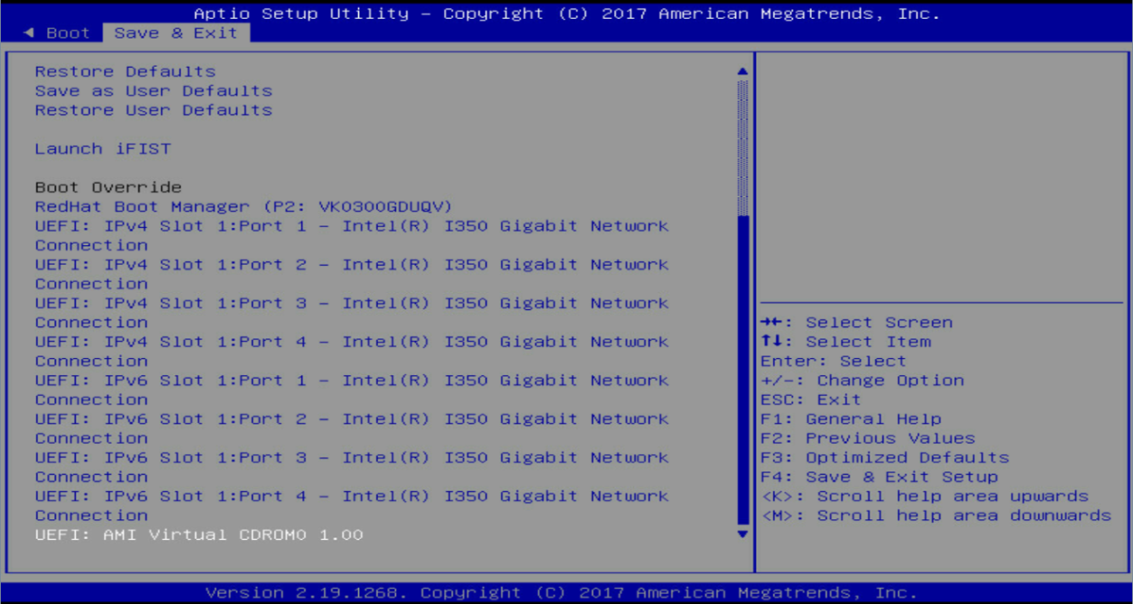
6. Click the Save & Exit tab, and then select the boot option for PXE in the Boot Override area.
¡ For UEFI boot mode, select the port connecting to the PXE server. In this example, port 1 connects to the PXE server.
Figure 7 PXE boot options in UEFI boot mode
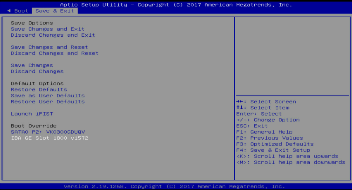
¡ For Legacy boot mode, select the only option. All ports on the network adapter share the same PXE boot option.
Figure 8 PXE boot options in Legacy boot mode
Mounting an OS image through a remote console
|
|
IMPORTANT: To avoid OS installation failure caused by connection errors in a WAN, mount an OS image in the same LAN as the server. |
This section mounts a virtual CD/DVD.
To mount an OS image through a remote console:
1. Log in to the server from the HDM console.
2. Select Media > Virtual Media Wizard from the navigation bar.

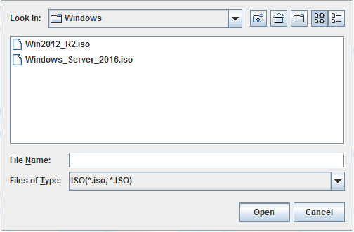
3. Click the CD/DVD tab, and then click Browse in the CD/DVD Media: I area. In the dialog box that opens, select a CD/DVD file, and then click Open.
Figure 10 Selecting a CD/DVD file
4. Click Connect to complete mounting the CD/DVD image file.
5. Display the mounted image. Enter the BIOS Setup Utility, and then click the Save & Exit tab. If you can find the mounted image file in the Boot Override area, the file has been mounted successfully.
Figure 11 Displaying the mounted image
Configuring RAID
Installing the OS on a logical disk improves server's read/write performance and provides fault tolerance through data verification, which improves system stability.
For more information about RAID configuration, see H3C Servers Storage Controllers User Guide.
Setting the BIOS boot mode
The server supports two BIOS boot modes: Legacy and UEFI. By default, the boot mode is UEFI. Support for the BIOS boot modes varies by operating system. For more information, see the operating system compatibility matrixes for the server.
|
|
IMPORTANT: · To install the OS on an NVMe SSD, you must set the BIOS boot mode to UEFI. · In Legacy mode, DCPMMs cannot be used for operating system installation. · To use the Legacy mode, configure the first boot drive, and install the OS on the drive. For more information, see configuring boot options in H3C Servers Storage Controllers User Guide. |
To set the BIOS boot mode:
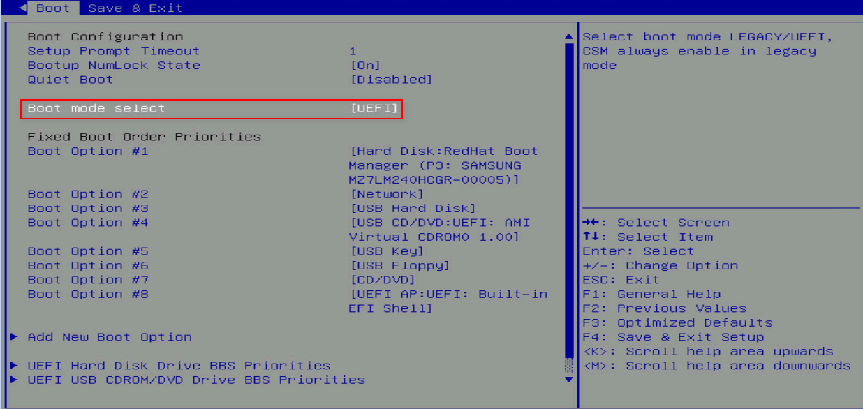
1. In the BIOS Setup Utility, click the Boot tab, select Boot mode select, and then press Enter.
Figure 12 Setting the BIOS boot mode
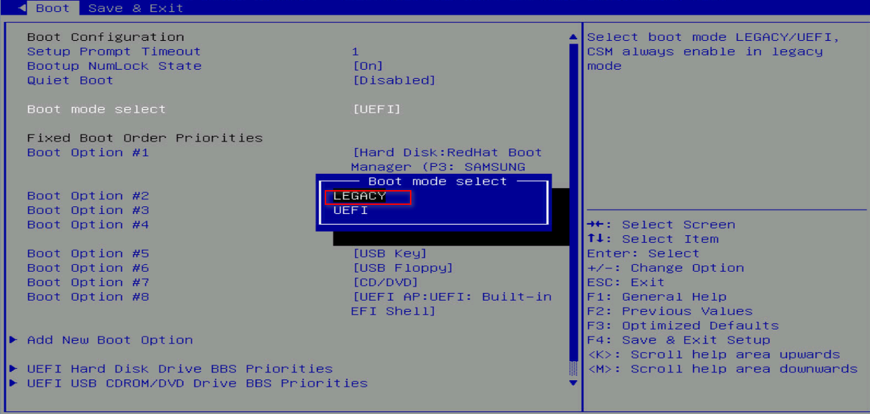
2. Select the Legacy or UEFI mode, and then press Enter.
Figure 13 Selecting a BIOS boot mode
3. Press F4 to save the configuration and reboot the server.
Selecting the boot media
1. Start the server, and press F7 at the prompt, as shown in Figure 14.
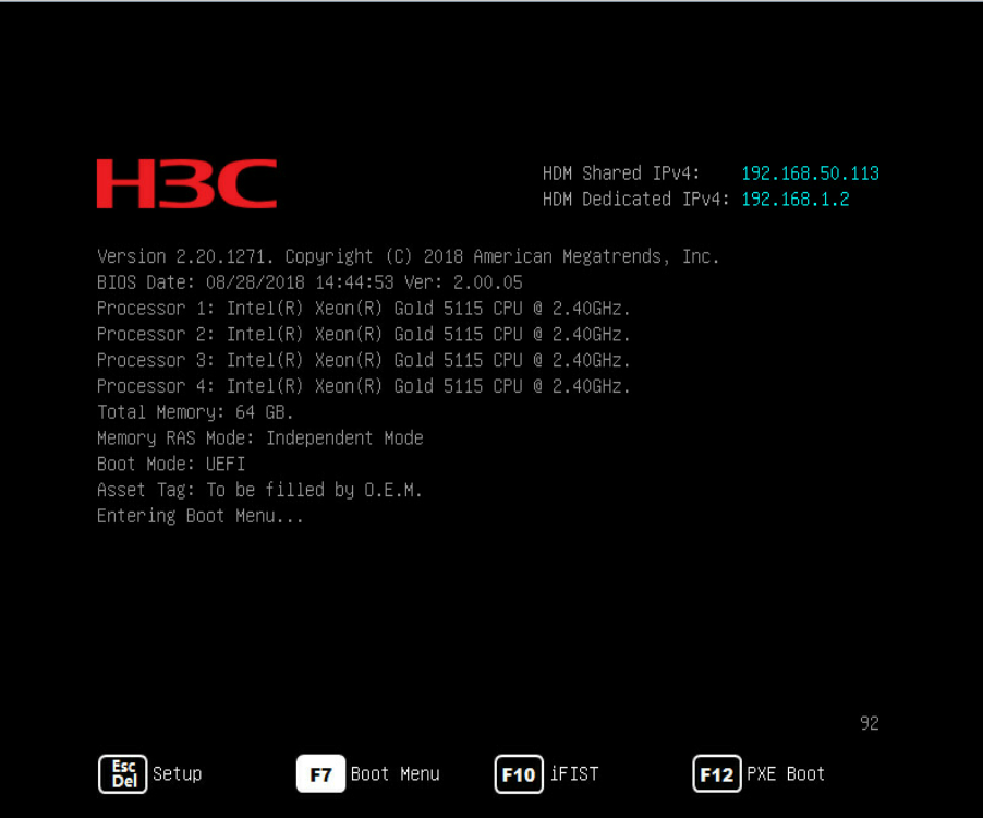
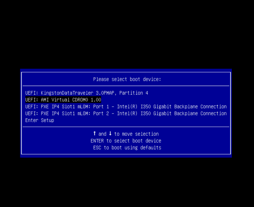
2. Select the boot media that contains the OS image. This section provides figures for selecting physical optical drive GK-DT-STDVDRAM and virtual media AMI Virtual CDROM0 mounted from the remote console as examples.
Figure 15 Selecting physical optical drive GK-DT-STDVDRAM as the boot media
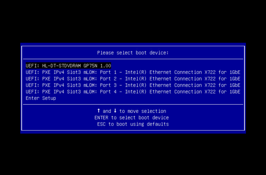
Figure 16 Selecting virtual media AMI Virtual CDROM0 as the boot media
Installing the OS
The OS installation wizard might vary by OS type and OS version. This document introduces the installation procedures for some common Windows Server, RedHat, CentOS, SUSE, VMware, and Ubuntu OSs. For more information about another OS, access the official website for the OS.
Installing a Windows OS
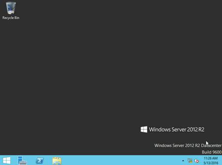
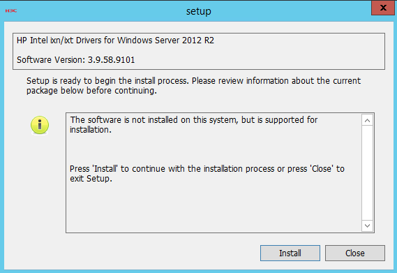
The installation procedure is the same for different Windows OS versions. This section installs Windows Server 2012 R2 and the storage controller driver.
Make sure both the OS image and the storage controller driver file have been mounted to the server. You can mount a file to the server through a CD/DVD, USB disk, or virtual media.
A Windows OS cannot be installed on a dual SD card.
To install a Windows OS:
1. Enter the BIOS and select boot options. For more information, see "Selecting the boot media."
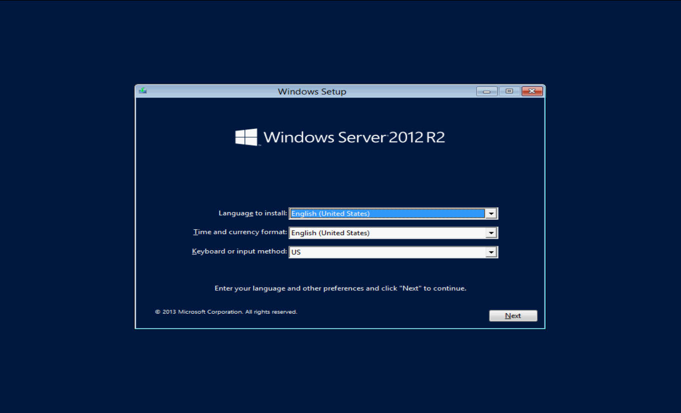
2. Set the language, time, and keyboard layout, and then click Next, as shown in Figure 16.
Figure 17 Setting the language, time, and keyboard layout
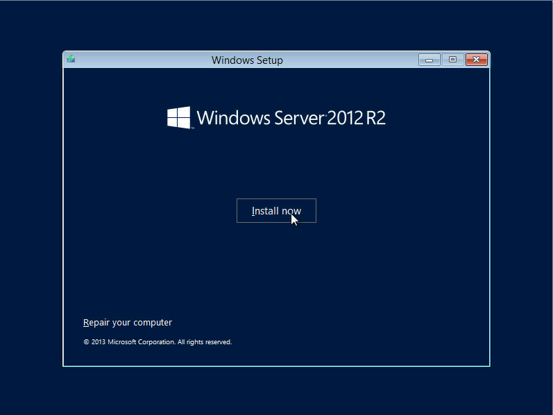
3. Click Install now.
Figure 18 Starting installing Windows
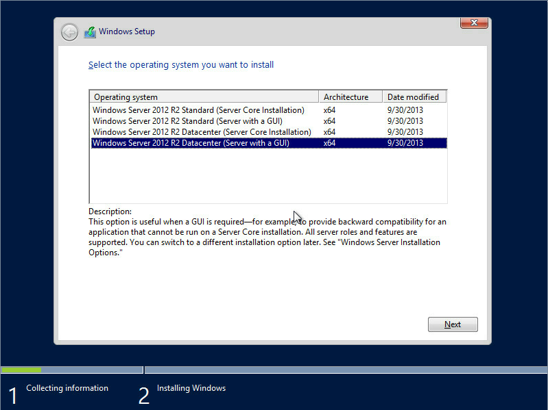
4. Select an OS version, and then click Next.
As a best practice, select an OS with a GUI. This example selects Windows Server 2012 R2 Datacenter (Server with a GUI).
Figure 19 Selecting an OS version
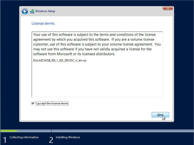
5. Select I accept the license terms, and then click Next.
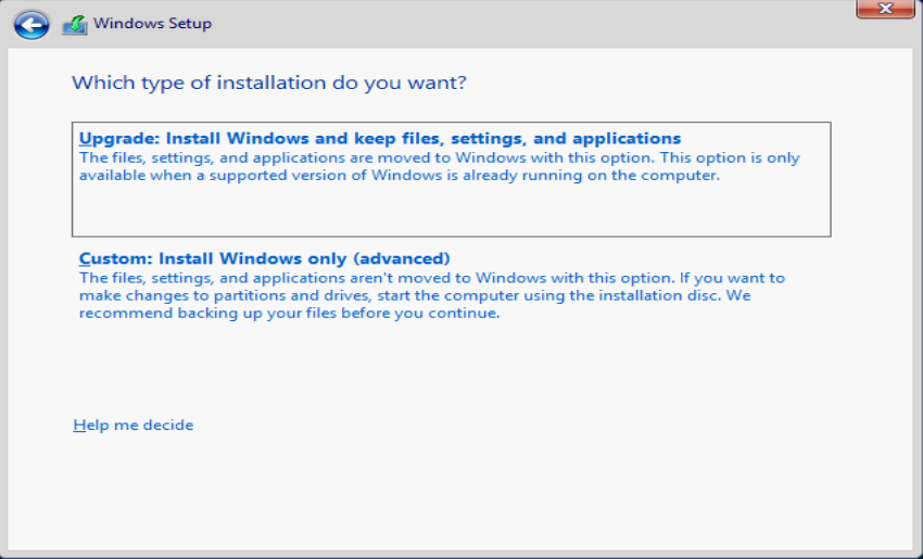
6. Select an installation type, Custom or Upgrade.
To install a new OS, select Custom. To upgrade your OS, select Upgrade.
This example selects the Custom type.
Figure 21 Selecting an installation type
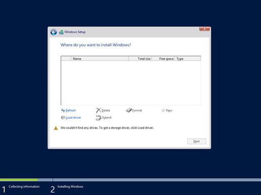
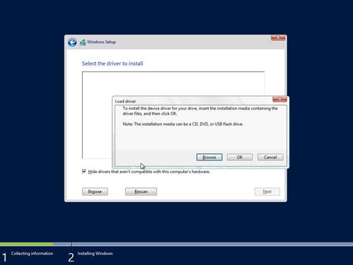
7. Click Load Driver, and then click Browse.
|
|
CAUTION: Load the storage controller driver when installing a Windows OS to avoid the following issues: · The disk cannot be detected (see Figure 21). · The OS cannot be accessed after installation. |
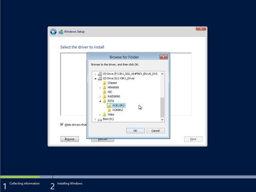
8. Select the path where the driver is located, and then click OK.
Figure 24 Selecting the driver path
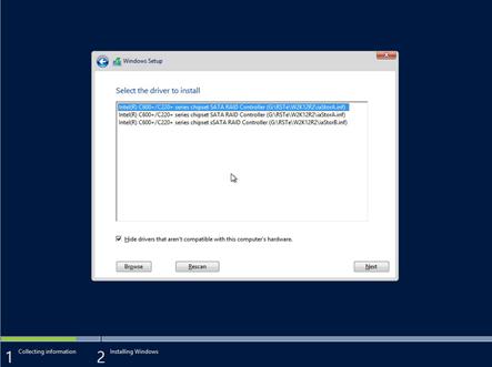
9. Select the driver to install, and then click Next.
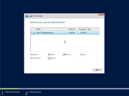
10. Select the destination drive to install the OS, and then click Next.
Figure 26 Loading storage controller driver completed
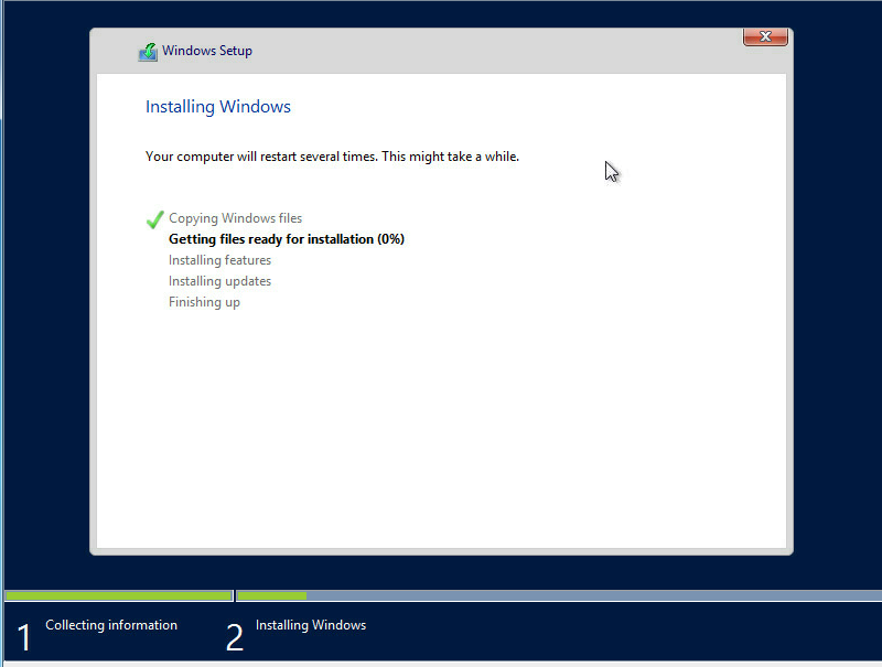
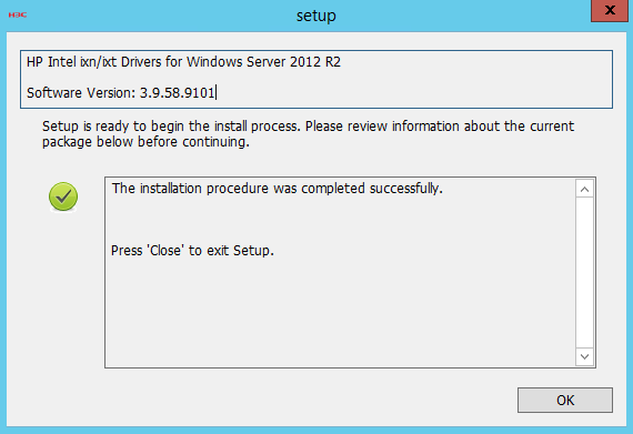
11. Wait for the system to complete OS installation.
Figure 27 Installing the OS
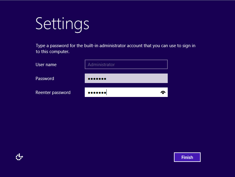
12. Set the password, and then click Finish after the system completes installation and enters the Settings page.
The user name is Administrator, which cannot be modified.
Figure 28 Setting the password
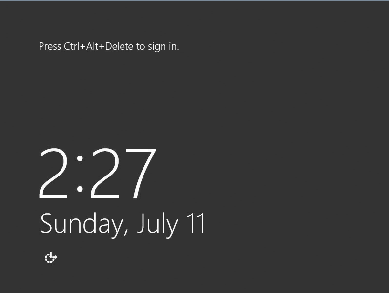
13. Press Ctrl+Alt+Delete on the keyboard of the remote console as prompted.
Figure 29 OS installation completed
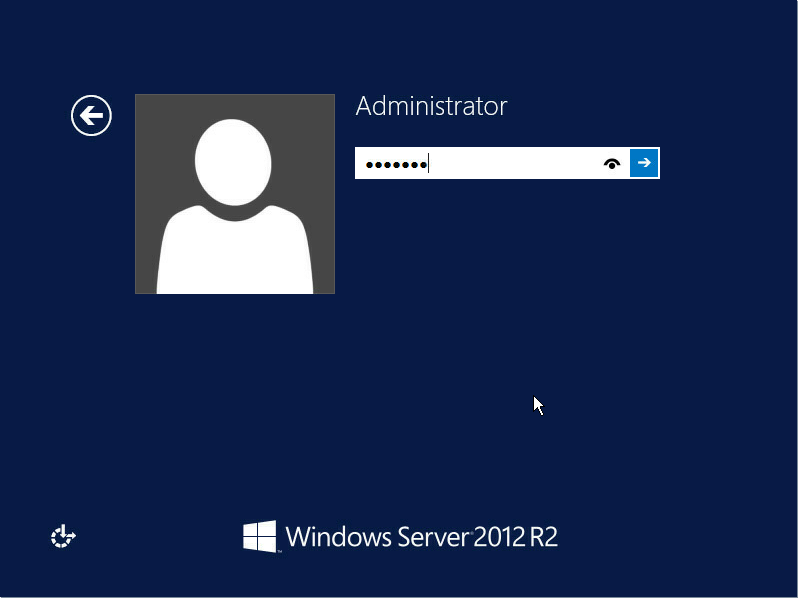
14. Enter the administrator password.
For the OS to correctly identify hardware devices, install the Chipset driver after OS installation.
Figure 30 Entering the administrator password
Installing a Red Hat/CentOS 6.x OS
The installation procedures are similar for Red Hat and CentOS 6.x OSs. This section installs Red Hat Enterprise Linux 6.8 and the storage controller driver.
Make sure both the OS image and the storage controller driver file have been mounted to the server. You can mount a file to the server through a CD/DVD, USB disk, or virtual media.
To install a Red Hat/CentOS 6.x OS:
1. Enter the BIOS and select boot options. For more information, see "Selecting the boot media."
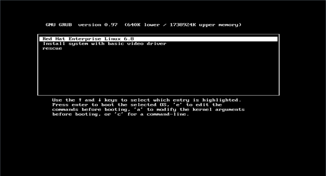
2. Select Red Hat Enterprise Linux 6.8, and then press e as prompted, as shown in Figure 31.
Figure 32 Confirming OS installation
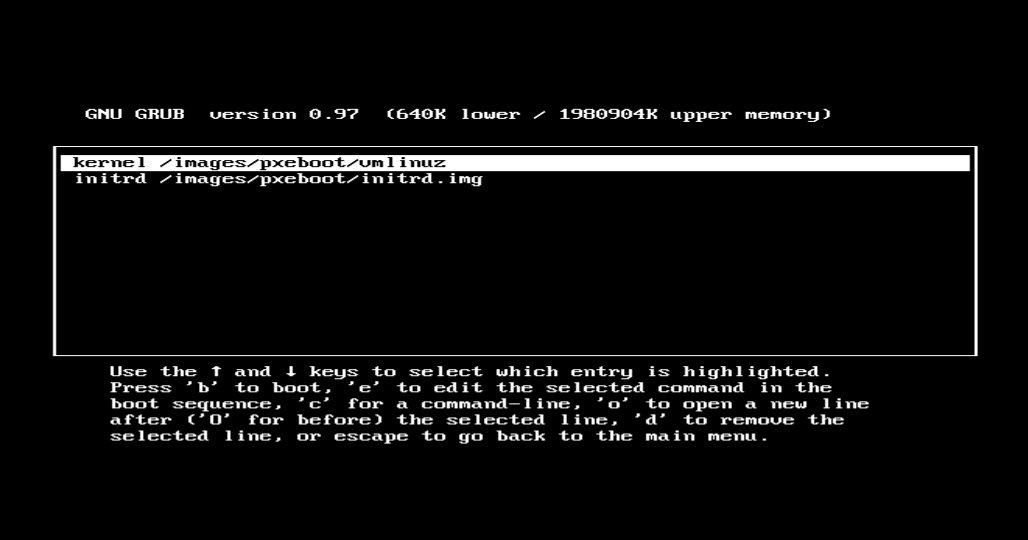
3. Select the line that starts with kernel, and then press e.
Figure 33 Selecting the line that starts with kernel
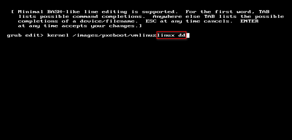
4. Input the linux dd command, and then press Enter. Then press b to start installation.
Figure 34 Entering the kernel page
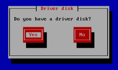
5. On the page that opens, select Yes.
Figure 35 Selecting a driver disk
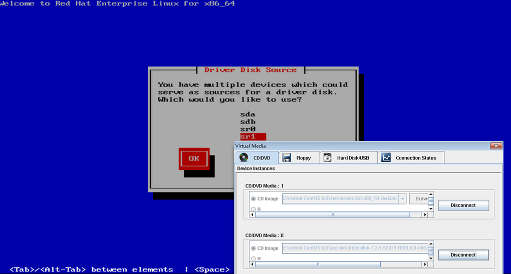
6. Select the mirrored interface to mount the driver disk.
Figure 36 Selecting the mirrored interface
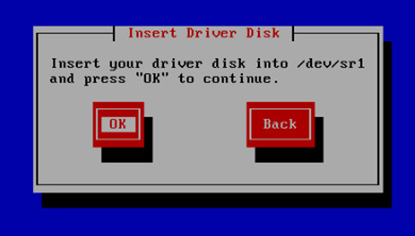
7. Click OK.
Figure 37 Confirming the next step
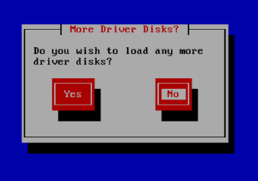
8. Click No to not load any other drivers and enter self-test.
Figure 38 Canceling loading any other drivers
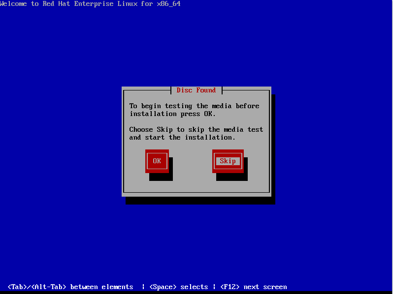
9. Press Tab, select OK or Skip, and then press Enter. This example selects Skip.
Figure 39 Confirming media test
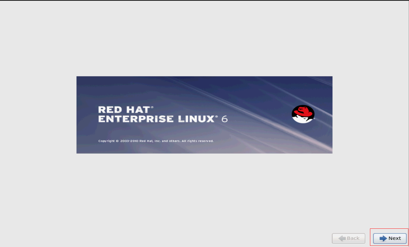
10. Click Next.
Figure 40 Preparing OS configuration
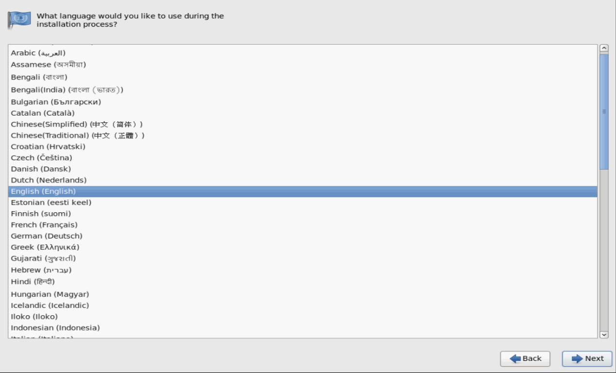
11. Select the language, and then click Next.
Figure 41 Selecting the language
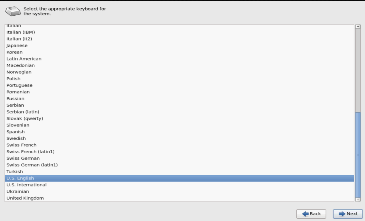
12. Select the keyboard, and then click Next.
Figure 42 Selecting the keyboard
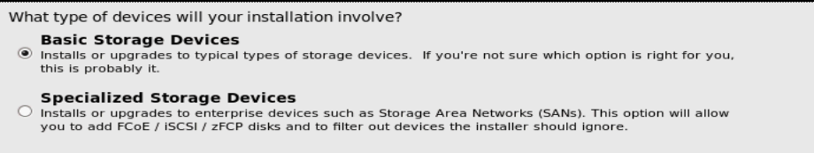
13. Select the device type, Basic Storage Devices or Specialized Storage Devices, and then click Next.
This example selects Basic Storage Devices.
Figure 43 Selecting the device type
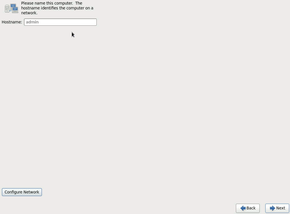
14. Enter the host name in the Hostname field, and then click Next.
To configure the network, click Configure Network on the lower left corner of the page. This example does not configure the network.
Figure 44 Setting the host name
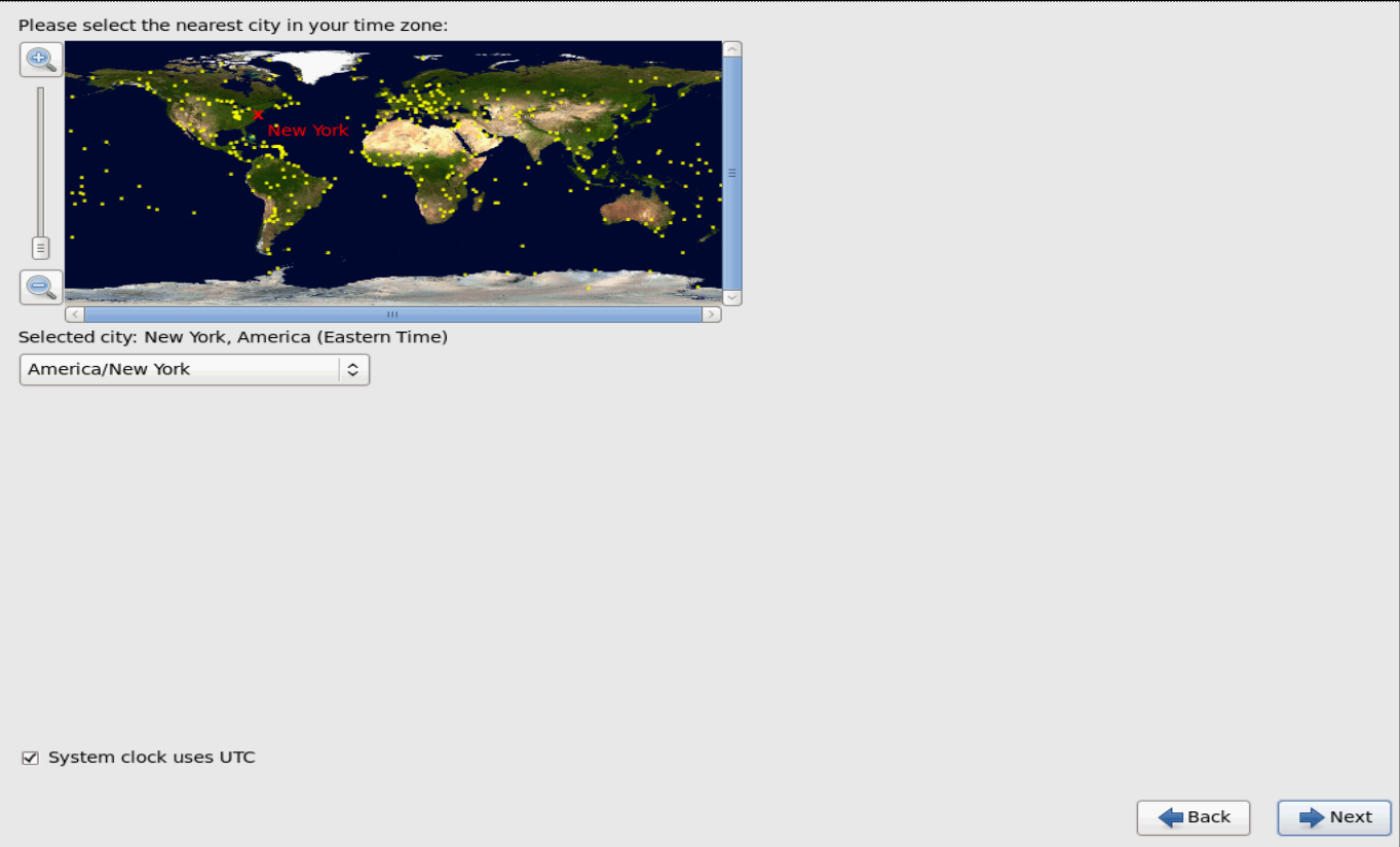
15. Select your time zone, and then click Next.
Figure 45 Selecting your time zone
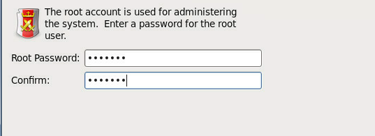
16. Set the root password, and then click Next.
Figure 46 Setting the root password
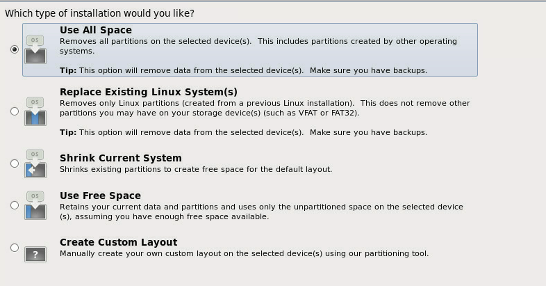
17. Select the type of installation, and then click Next. This example selects Use All Space.
Figure 47 Selecting the type of installation
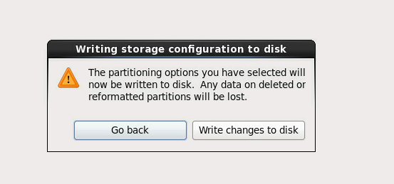
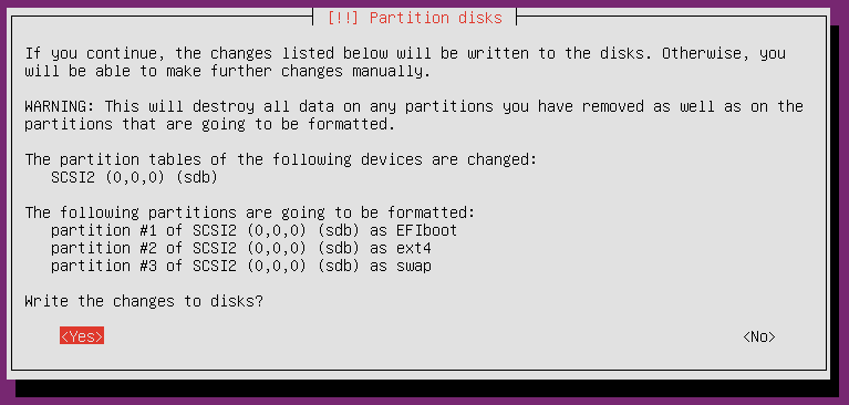
18. Back up all data on the disk, and then click Write changes to disk to format the disk.
Figure 48 Confirming the formatting operation
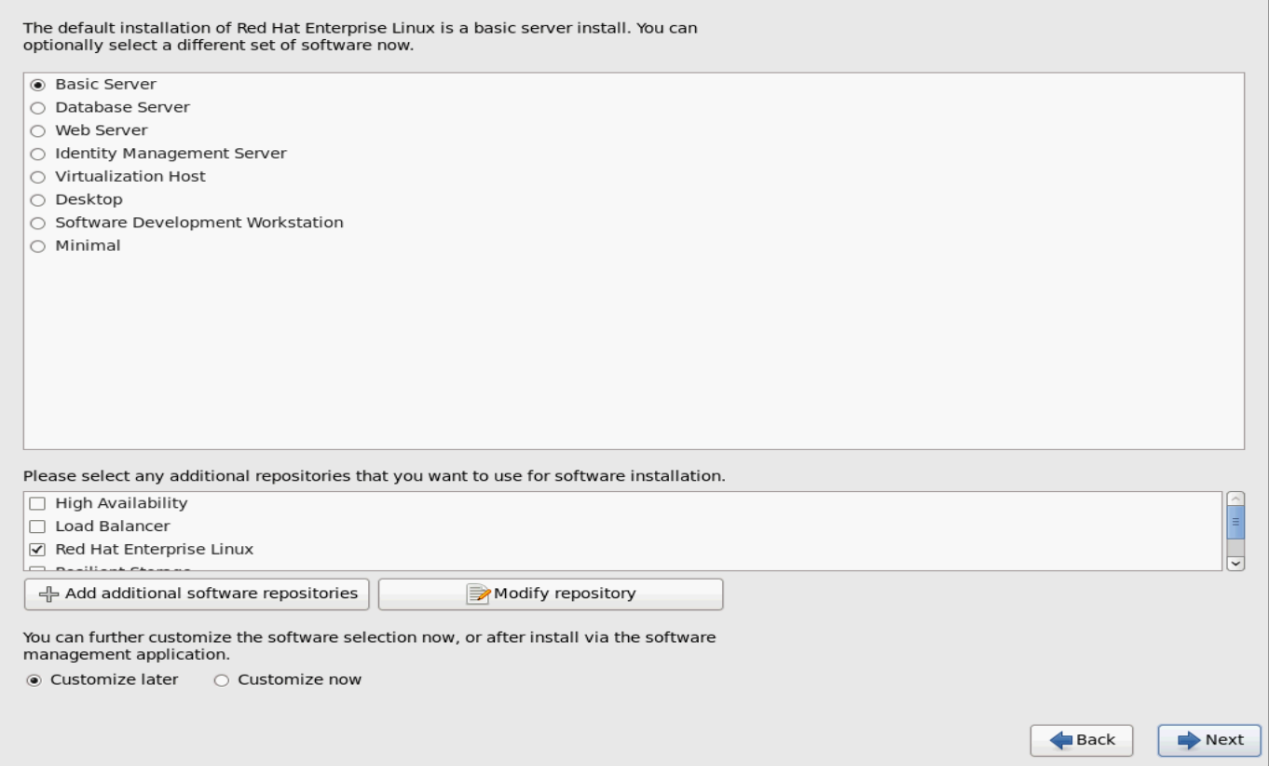
19. Select a server type and additional repositories, select Customize now, and then click Next.
The following server types are available:
¡ Basic Server—Base, without GUI.
¡ Database Server—Base, plus MySQL database, without GUI.
¡ Web Server—Base, plus PHP, Web server, and MySQL database client, without GUI.
¡ Identity Management Server.
¡ Virtualization Host—Base, virtualization platform.
¡ Desktop—Basic desktop, including commonly-used desktop software.
¡ Software Development Workstation—Includes base, virtualization platform, desktop platform, and development tools.
¡ Minimal—Core.
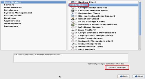
20. Select Base, and then click Optional packages.
Figure 50 Server installation options
21. Click Close, and then click Next. For the OS to start correctly, make sure the boot package is not selected if the BIOS boot mode is UEFI.
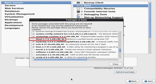
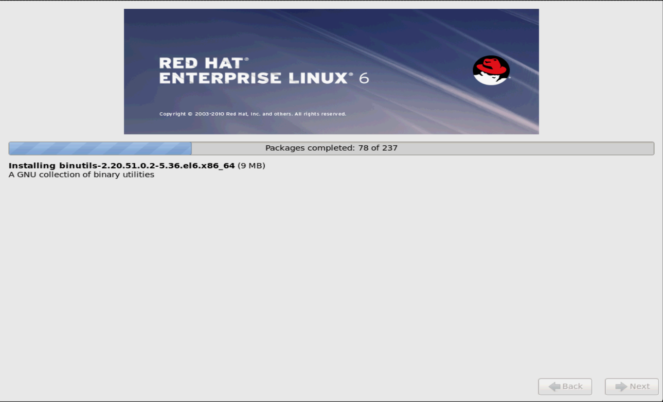
Figure 52 Installing the OS
22. Click Reboot to reboot the server.
Figure 53 Rebooting the server
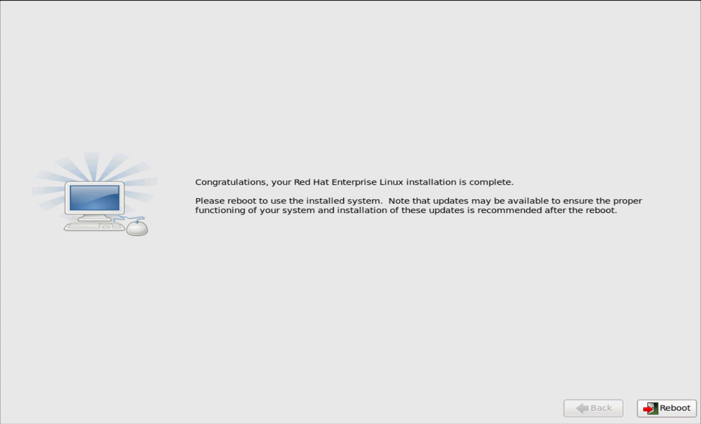
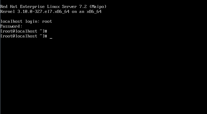
Figure 54 Logging in to the OS

Installing a Red Hat 7.x, Red Hat 8.x, CentOS 7.x, or CentOS 8.x OS
The installation procedures are similar for Red Hat 7.x, Red Hat 8.x, CentOS 7.x, and CentOS 8.x OSs. This section installs Red Hat Enterprise Linux 7.2 and the storage controller driver.
Make sure both the OS image and the storage controller driver file have been mounted to the server. You can mount a file to the server through a CD/DVD, USB disk, or virtual media.
To install a Red Hat/CentOS 7.x OS:
1. Enter the BIOS and select boot options. For more information, see "Selecting the boot media."
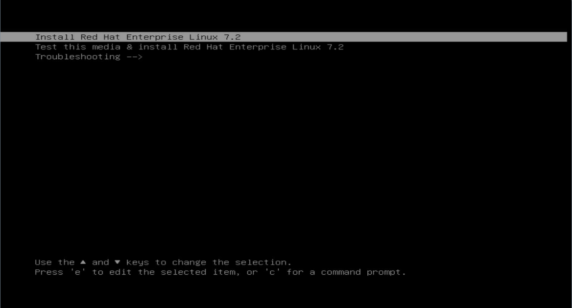
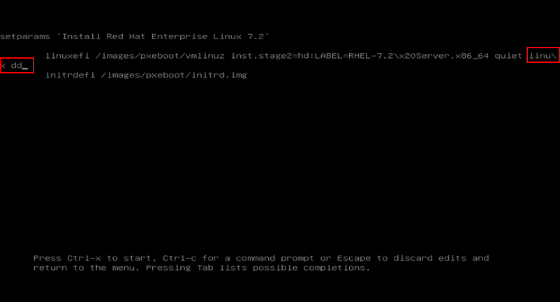
2. Select Red Hat Enterprise Linux 7.2, and then press e as prompted, as shown in Figure 54.
Figure 55 Confirming OS installation
3. Input linux dd at the end of the line that starts with linuxefi, and then press F10 or Ctrl+X to start installation.
Figure 56 Parameter configuration
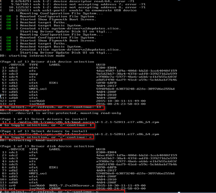
4. Perform the following steps to configure the parameters:
a. Display the location of the driver. In this example, sr1 has a driver mounted, so you select 13.
b. Enter 1 to select the rpm file.
c. Enter c to continue installation.
If not all drivers are listed on the page, enter r to refresh the driver list.
Figure 57 Parameter configuration
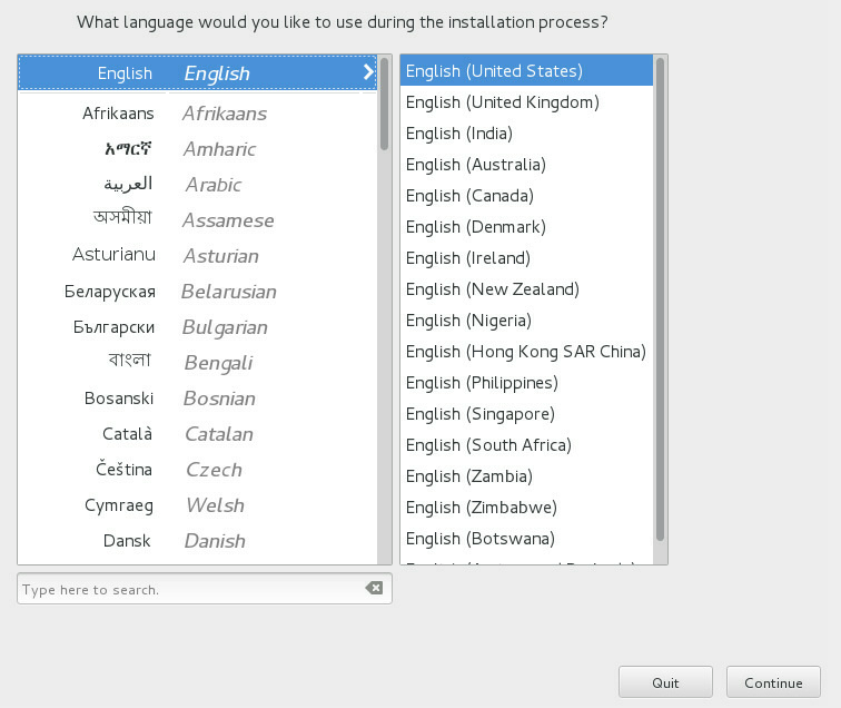
5. Select the system language, and then click Continue.
Figure 58 Selecting the language
6. Configure the options in Figure 58 as required.
If an icon has a ![]() mark, it indicates that the configuration is incorrect, and you must
reconfigure the option.
mark, it indicates that the configuration is incorrect, and you must
reconfigure the option.
The following describes only the steps for specifying a destination disk. The default settings are used for other options.
Figure 59 Option configuration
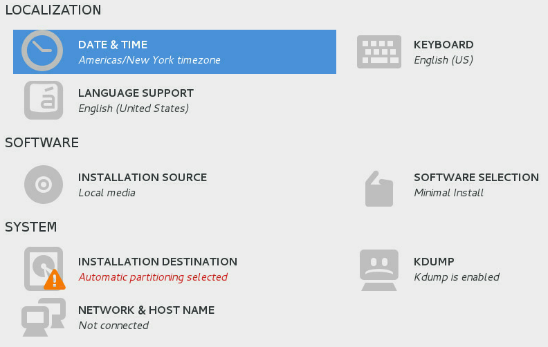
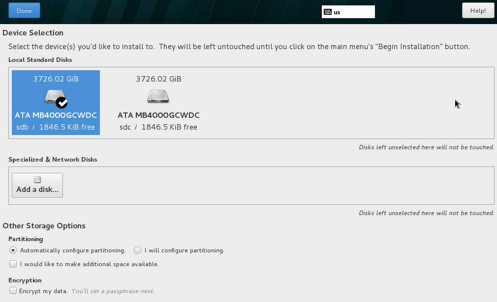
7. Click INSTALLATION DESTINATION. Select the disk where the OS is to be installed, and then click Done.
This example uses automatic partitioning. To use manual partitioning, select I will configure partitioning.
Then you must select Standard Partition from the New mount points will use the following partitioning scheme list for successful OS installation.
If you select manual partitioning in UEFI boot mode, you must create the /boot/efi partition, and the files in the partition must be in efipartition or fat format. If you do not do so, an error will occur during OS installation.
Figure 60 Selecting the disk to install the OS
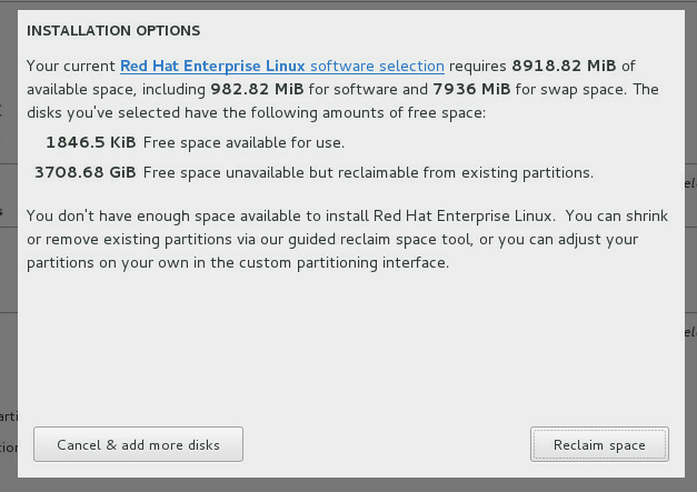
8. Click Reclaim space to format the disk when the following dialog box appears.
Figure 61 Confirming the formatting operation
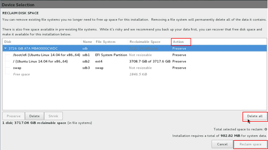
9. Click Delete all. When the status in the Action column changes to Delete, click Reclaim space to delete all partitions.
Figure 62 Deleting the current partitions
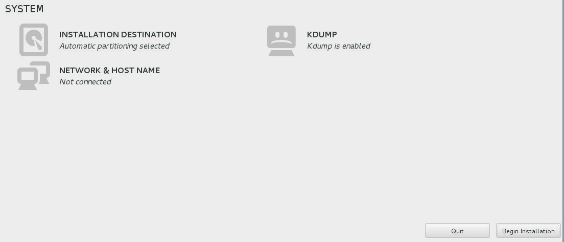
10. Click Begin Installation.
Figure 63 Starting installing the OS
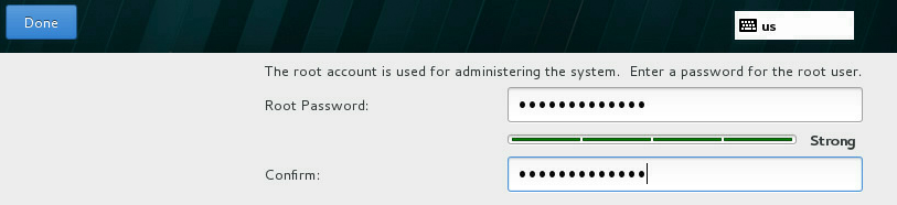
11. Click ROOT PASSWORD.
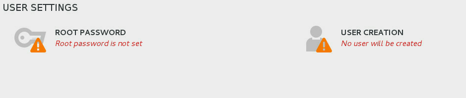
12. Enter the root password, and then click Done. If the password is too simple, the system gives a prompt. To accept the simple password, click Done twice.
Figure 65 Setting the root password
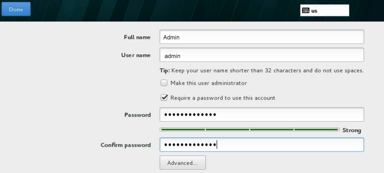
13. Click USER CREATION, create a new user account, set the password, and then click Done. If the password is too simple, the system gives a prompt. To accept the simple password, click Done twice.
Figure 66 Creating a user account
14. Wait for the system to complete installation.
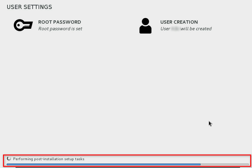
15. Click Reboot to reboot the server after the installation is complete.
Figure 68 Rebooting the server
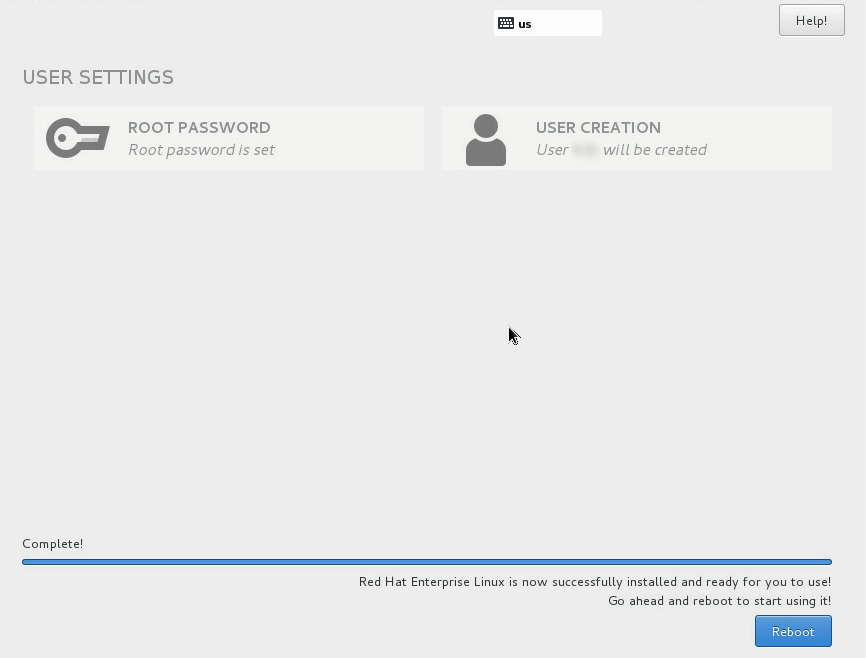
Figure 69 Logging in to the OS
Installing an SUSE OS
The installation procedures are similar for SUSE OSs. This example installs SLES 11 SP4.
You do not need to install the storage controller driver for an SUSE OS.
To install an SUSE OS:
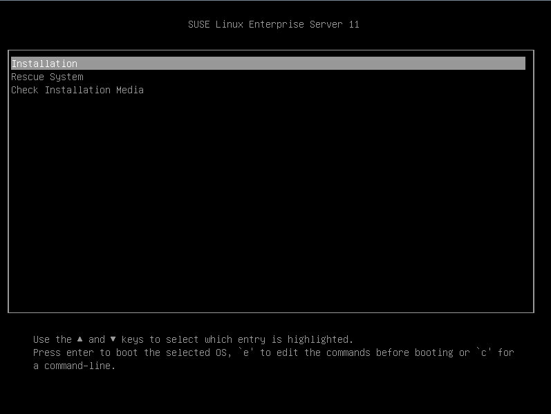
1. Enter the BIOS and select boot options. For more information, see "Selecting the boot media."
2. As shown in Figure 69, click Installation, and then press E.
Figure 70 Confirming OS installation
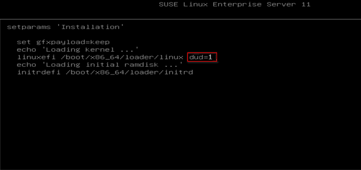
3. Input dud=1 at the end of the line that starts with linuxefi, and then press F10 to start installation.
4. Open the soft keyboard, and press Ctrl+Alt+F2 to enter the CLI console.
Figure 72 Entering the CLI console
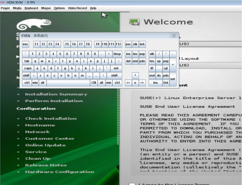
5. Enter the modinfo aacraid command to identify whether the driver has been installed successfully. Press Ctrl+Alt+F7 to continue OS installation.
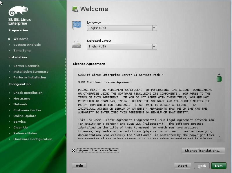
6. Set the language and keyboard layout of the OS, select I Agree to the License Terms, and then click Next.
Figure 73 Setting the language and keyboard layout
7. Select Check ISO File as required, and then click Next.
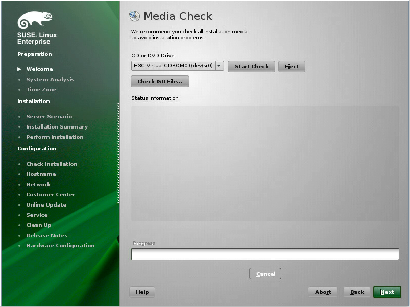
8. Click Next.
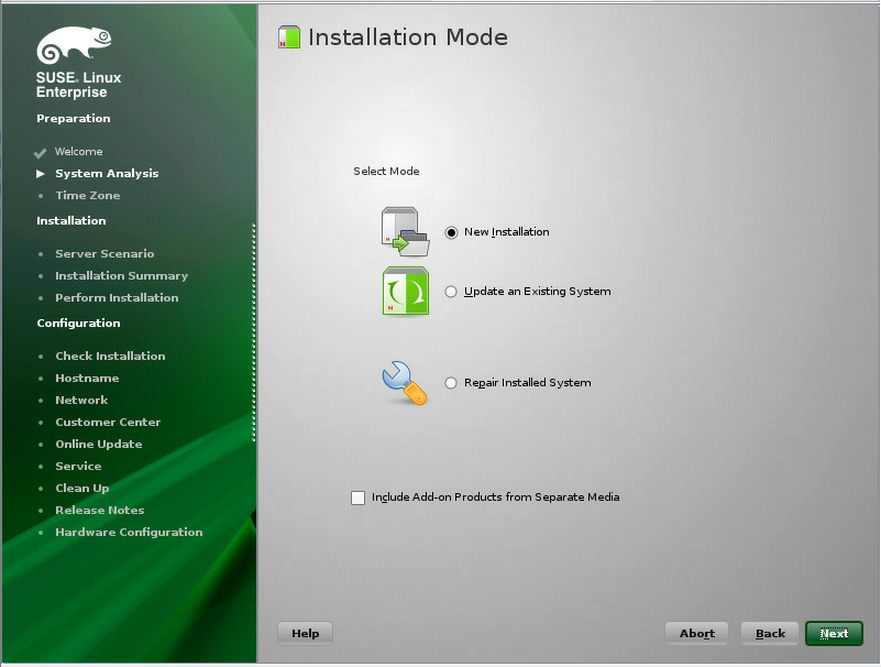
9. Select an installation mode and then click Next. This example selects New Installation.
Figure 76 Selecting an installation mode
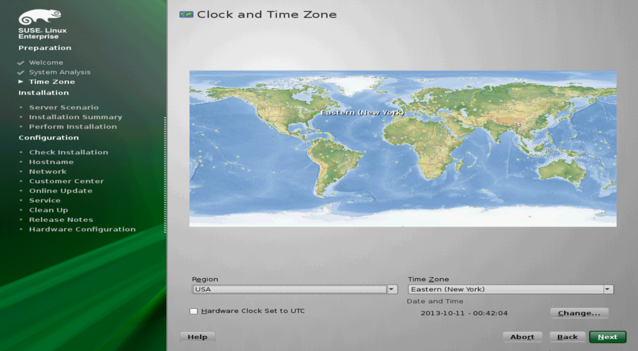
10. Select your time zone, and then click Next.
Figure 77 Selecting your time zone
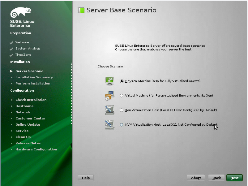
11. Select the server base scenario, and then click Next. As a best practice, select Physical Machine for new installation.
Figure 78 Selecting the server base scenario
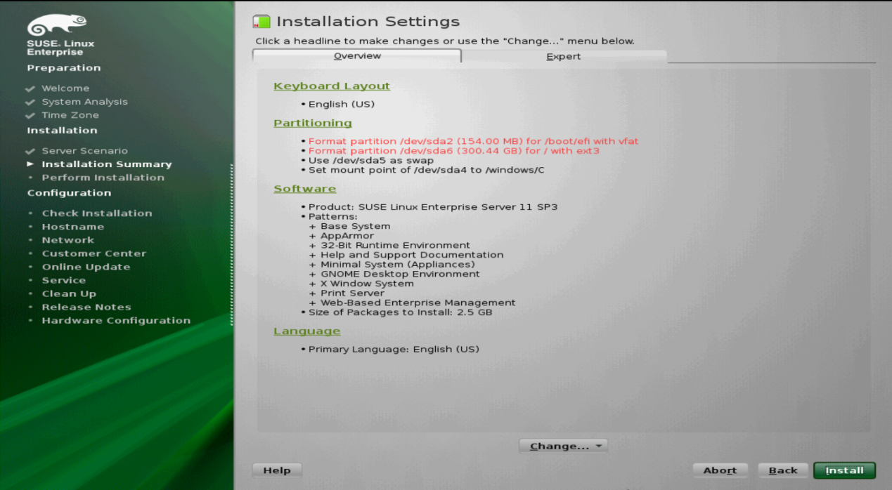
12. To use the default settings, click Install. The system will start OS installation.
13. To manually partition the disk:
a. Click Partitioning, on the Preparing Hard Disk page select a partitioning method, and then click Next.
If you select 1.IDE Disk, the system will automatically partition the disk based on the size of the disk. If you select Custom Partitioning, you can manually partition the disk as needed. This example selects Custom Partitioning.
Figure 80 Preparing hard disk

b. From the left navigation tree, select Hard Disks > sda.
The following partitions must be added:
- swap—Switching partition to implement virtual memory. As a best practice, set its size to one or twice of the physical memory.
- /boot/efi—System boot file partition. It must be in the efi partition or fat format. As a best practice, set the size to 100 MB to 200 MB.
- /—Root partition to save system software and files.
Figure 81 Partitioning the disk

c. Click Add. On the page that opens, set the partition size, and then click Next.

d. Select a file system and mount point, and then click Finish.
Figure 83 Setting the partition

e. To install software, click Software. On the page that opens, select software and set system tasks, and then click OK.

14. Click Install.

15. After the installation is complete, click Next. The system will automatically reboot.
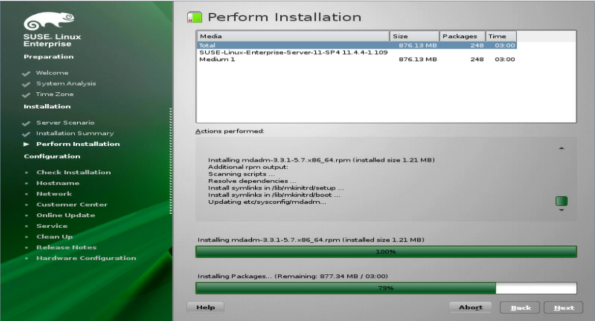
Figure 86 Performing installation

Figure 87 OS rebooting

16. Set the root password, and then click Next when the following page appears.
Figure 88 Setting the root password

17. Click Next as prompted until the OS configuration is complete.
The suse 12xxxx and UEFI OS and suse linux xxx boot options will appear on the BIOS Setup Utility for an SUSE 12 OS and SUSE 11 OS, respectively.
Figure 89 OS installation completed

Installing a VMware ESXi OS
For successful OS installation, you must use an OS image integrated with a storage controller driver if a storage controller has been installed on the server.
As a best practice, do not install a VMware ESXi OS on an embedded RSTe RAID controller.
The installation procedures are similar for different VMware ESXi OS versions. This example installs VMware ESXi 6.0 U3 and the storage controller driver.
Make sure the OS image integrated with a storage controller driver has been mounted to the server.
Customizing an OS image integrated with a storage controller driver
For versions earlier than VMware ESXi 6.5
1. Download ESXi-Customizer and storage controller driver. You can download ESXi-Customizer from the Internet and a storage controller driver from the H3C website.
2. Run ESXI-Customizer.cmd, and perform the following tasks in the dialog box that opens:
¡ Select the original VMware ESXi ISO.
¡ Select an OEM.tgz file, a VIB file, or an Offline Bundle.
¡ Select the working directory.
3. Click Run.
Figure 90 Integrating an OS image and a storage controller driver

For VMware ESXi 6.5 and later versions
1. (Optional.) Update PowerShell to version 3.0.
a. Open CMD, and execute the Get-Host | Select-Object Version command to view the PowerShell version.
- If the version is 3.0 or later, go to step 2.
- If the version is earlier than 3.0, go to step b.
Figure 91 Viewing PowerShell version

b. Download the Windows6.1-KB2506143-x64.msu file at https://www.microsoft.com/en-us/download/details.aspx?id=34595, install the file, and then restart the system.
c. Execute the Set-ExecutionPolicy RemoteSigned command to set the execution policy to RemoteSigned.
a. Download VMware-PowerCLI-6.5.0 and ESXi-Customizer-PS from the Internet.
b. Install VMware-PowerCLI-6.5.0.
The VMwarePowerCLI icon appears on the desktop after installation, as shown in Figure 91.
Figure 92 VMware-PowerCLI-6.5.0 installation completed

3. Integrate an OS image and a storage controller driver.
a. Access the H3C website to obtain the storage controller driver package and decompress the package as shown in Figure 92.
Figure 93 Decompressing the storage controller driver package

b. Put the storage controller driver, original VMWare ESXi OS image, and ESXi-Customizer-PS in the same directory.
Figure 94 Preparing the driver, OS image, and ESXi-Customizer-PS

c. Run VMware PowerCLI, and execute the cd command to enter the directory where the driver resides.
Figure 95 Entering the directory where the driver resides

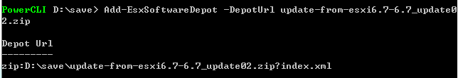
d. Execute the Add-esxsoftwareDepot –depoturl driver_file_name.zip command to load the driver file.
Figure 96 Loading the driver file

e. Execute the Get-EsxSoftwarePackage command to obtain the driver name. In this example, the driver name is smartpqi.
Figure 97 Viewing driver information

f. Execute the Add-esxsoftwareDepot –depoturl OS_image_file_name.zip command to load the OS image.
Figure 98 Loading the OS image
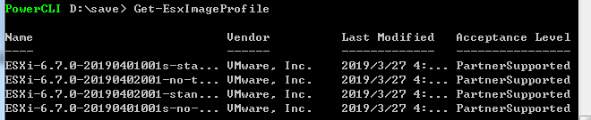
g. Execute the Get-EsxImageProfile command to obtain the name of the target configuration file. An OS image contains multiple configuration files for different installation scenarios. In this example, the OS image contains four configuration files. This section uses the third configuration file.
Figure 99 Viewing OS image information
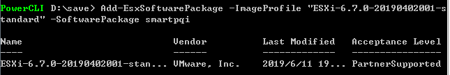
h. Execute the Add-EsxSoftwarePackage –ImageProfile configuration_file_name –SoftwarePackage driver_name command to integrate the OS image and the driver.
Figure 100 Integrating the OS image and the driver
i. Execute the Export-EsxImageProfile -NoSignatureCheck –ImageProfile configuration_file_name –ExportToIso –FilePath export_path_and_file_name command to export the OS image integrated with the driver.
Figure 101 Exporting the OS image integrated with the driver
![]()
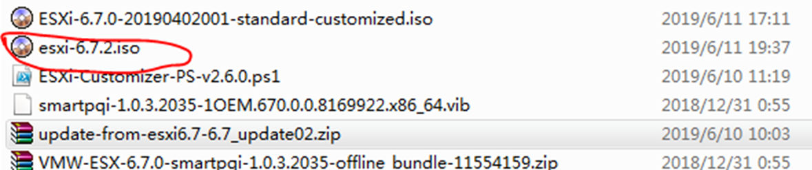
j. Verify that the OS image has been exported to the specified path with the specified name.
Figure 102 Obtaining the OS image integrated with the driver
Installing the OS
1. Enter the BIOS and select boot options. For more information, see "Selecting the boot media."
2. Wait for the system to load the file.
Figure 103 Loading ESXi installer
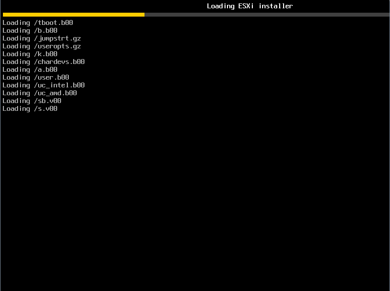
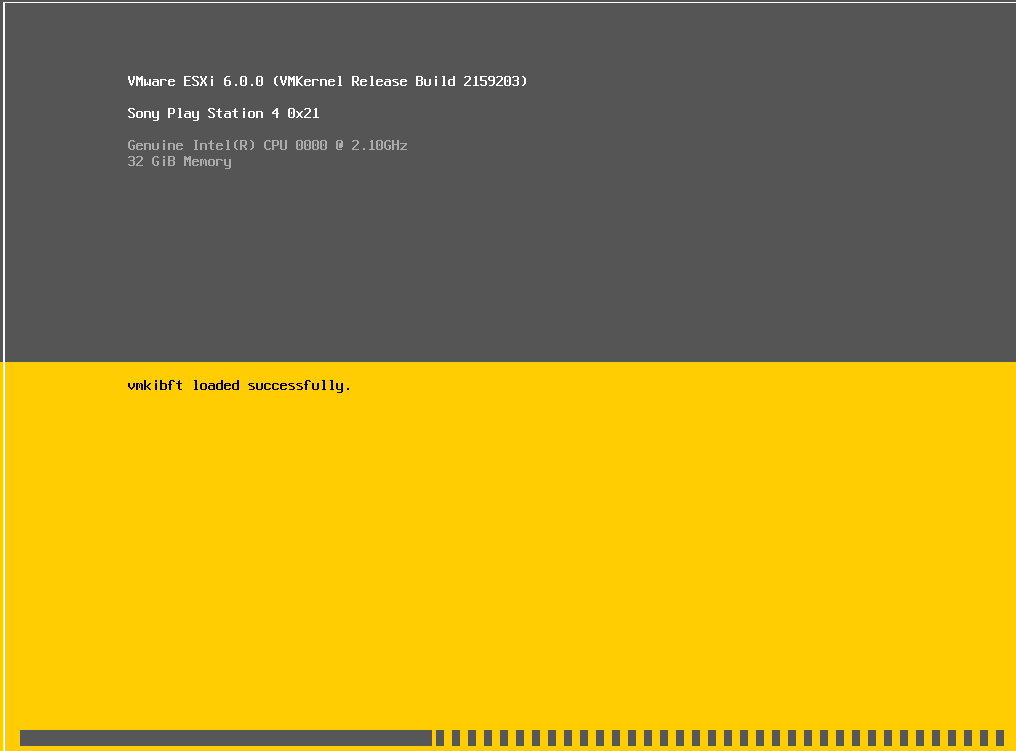
Figure 104 Loading the OS module
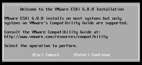
3. Press Enter as prompted to continue installation.
Figure 105 VMware ESXi installation
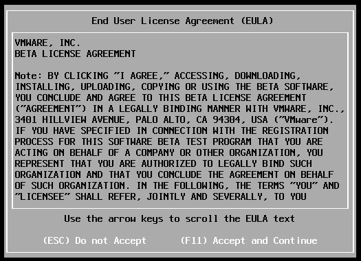
4. Press F11.
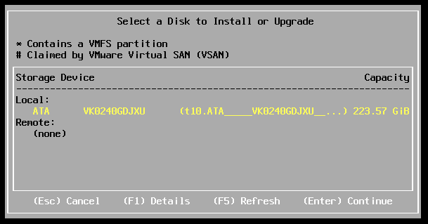
5. Select the disk to install the OS and then press Enter. To see details, press F1.
Figure 107 Selecting the disk to install the OS
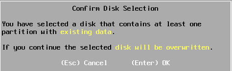
6. Confirm disk selection and then press Enter. To change to another disk, press Esc and then select another one.
Figure 108 Confirming disk selection
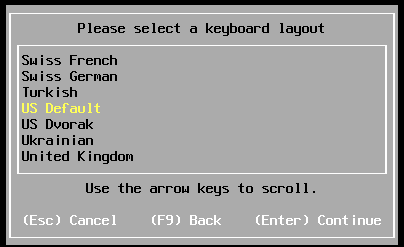
7. Select a keyboard layout as prompted, and press Enter when the following dialog box appears.
Figure 109 Selecting a keyboard layout
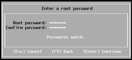
8. Set the root password, and then press Enter.
Figure 110 Setting the root password
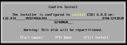
9. Press F11 to start installation.
Figure 111 Confirming VMware ESXi OS installation
10. Press Enter to reboot the server.
If the OS image is obtained from a CD/DVD or bootable USB disk, remove the CD/DVD or USB disk, and then press Enter to reboot the server.
Figure 112 OS installation completed
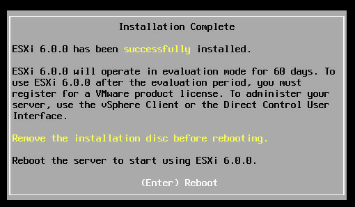
Figure 113 OS reboot completed
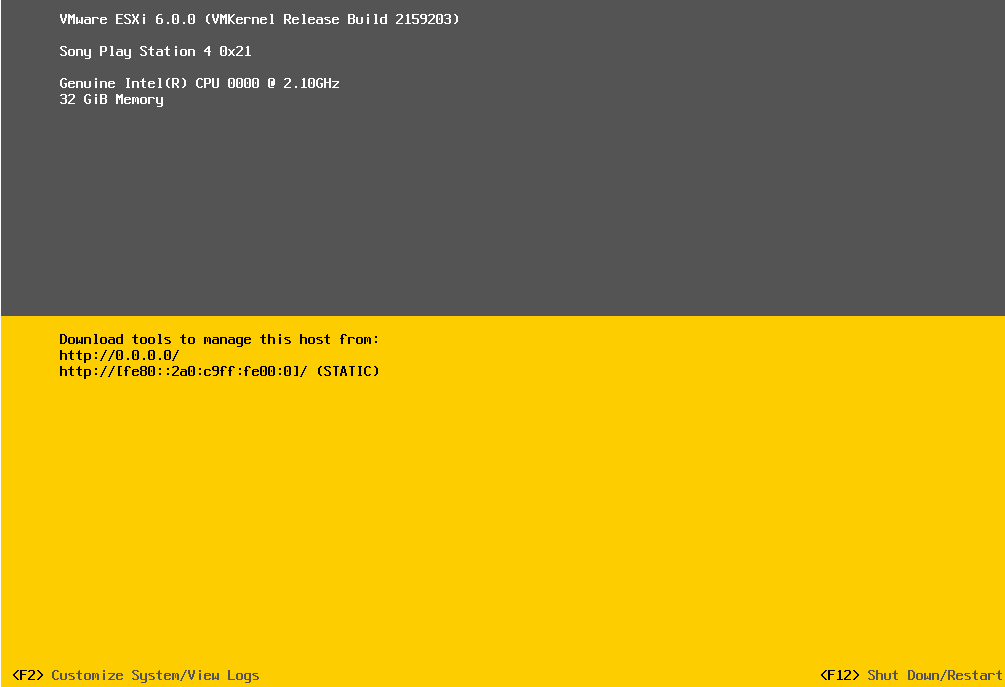
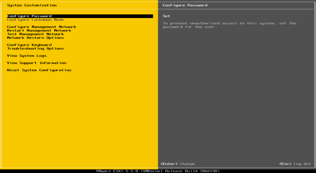
11. Press F2, enter the root password, and then press Enter.
The OS installation is complete when the page as shown in Figure 114 appears.
Figure 114 Entering the root password
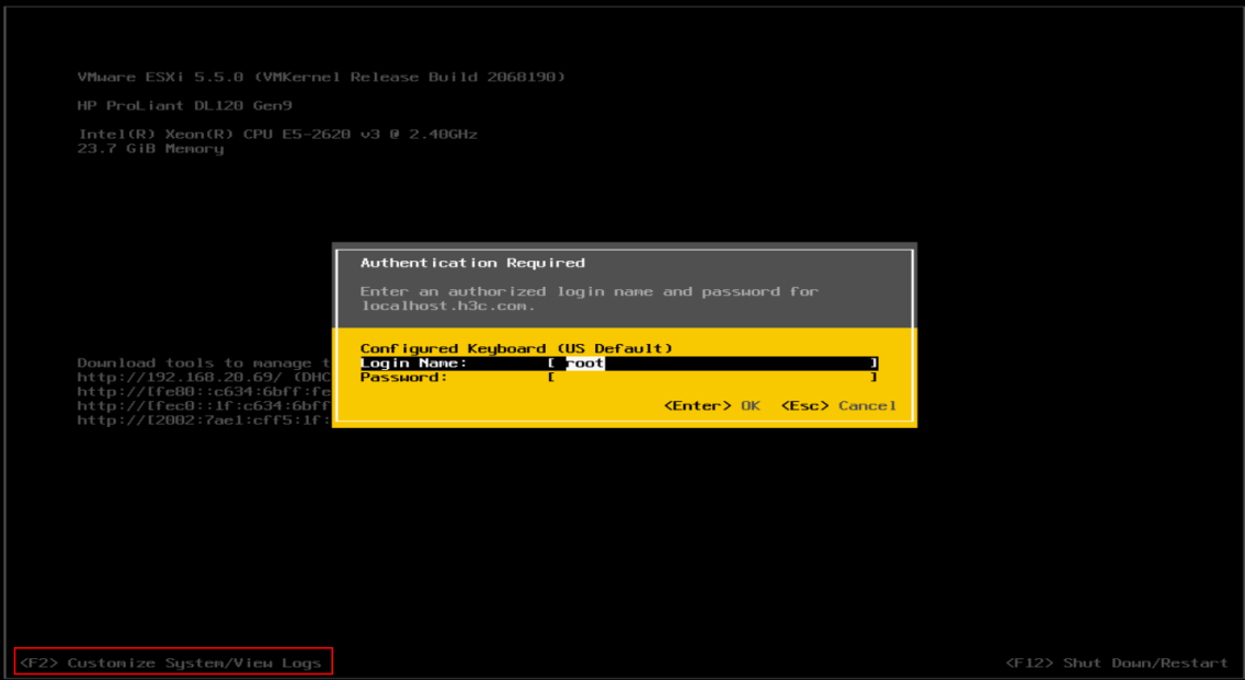
Figure 115 Configuring the password
Installing a Citrix OS
The installation procedures are similar for different VMware Citrix OS versions. This example installs Citrix XenServer 7.1 but does not install the storage controller driver.
To install a Citrix OS:
1. Enter the BIOS and select boot options. For more information, see "Selecting the boot media."
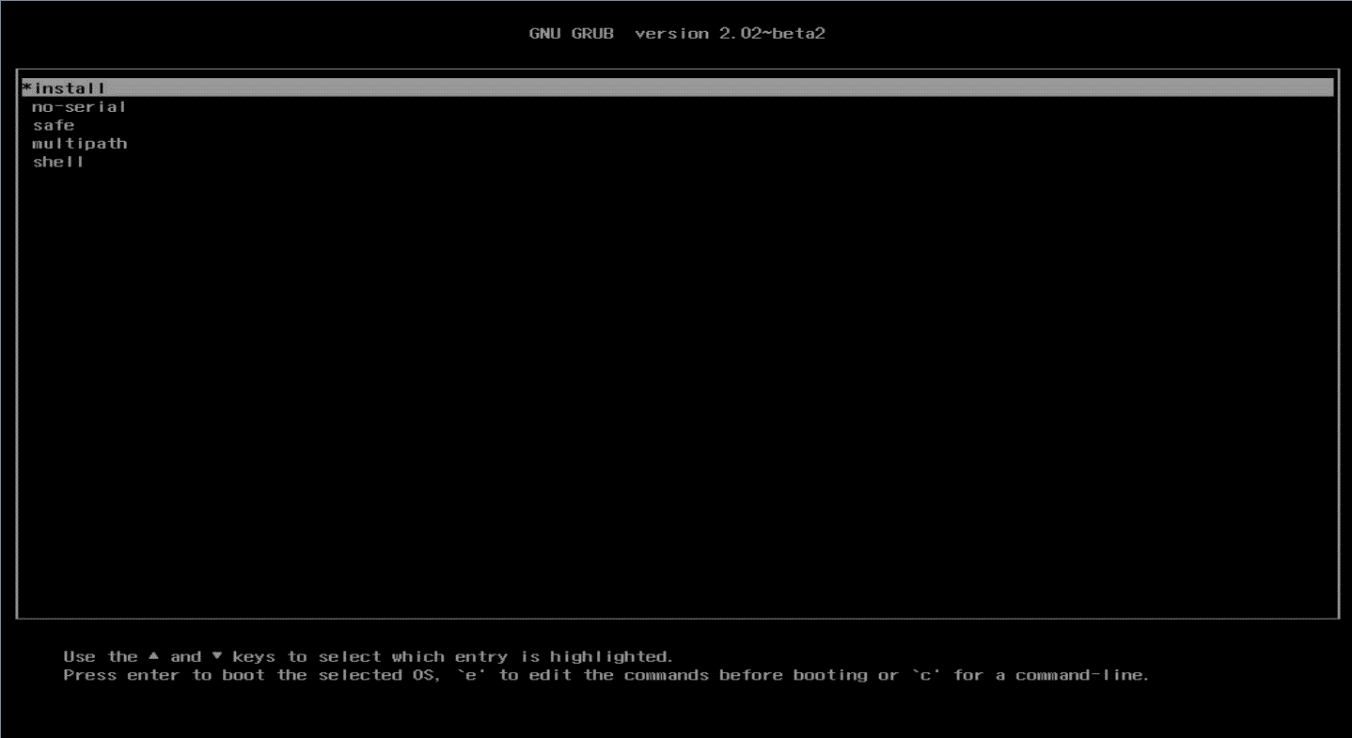
2. Select Install, and then press Enter.
Figure 116 Grub
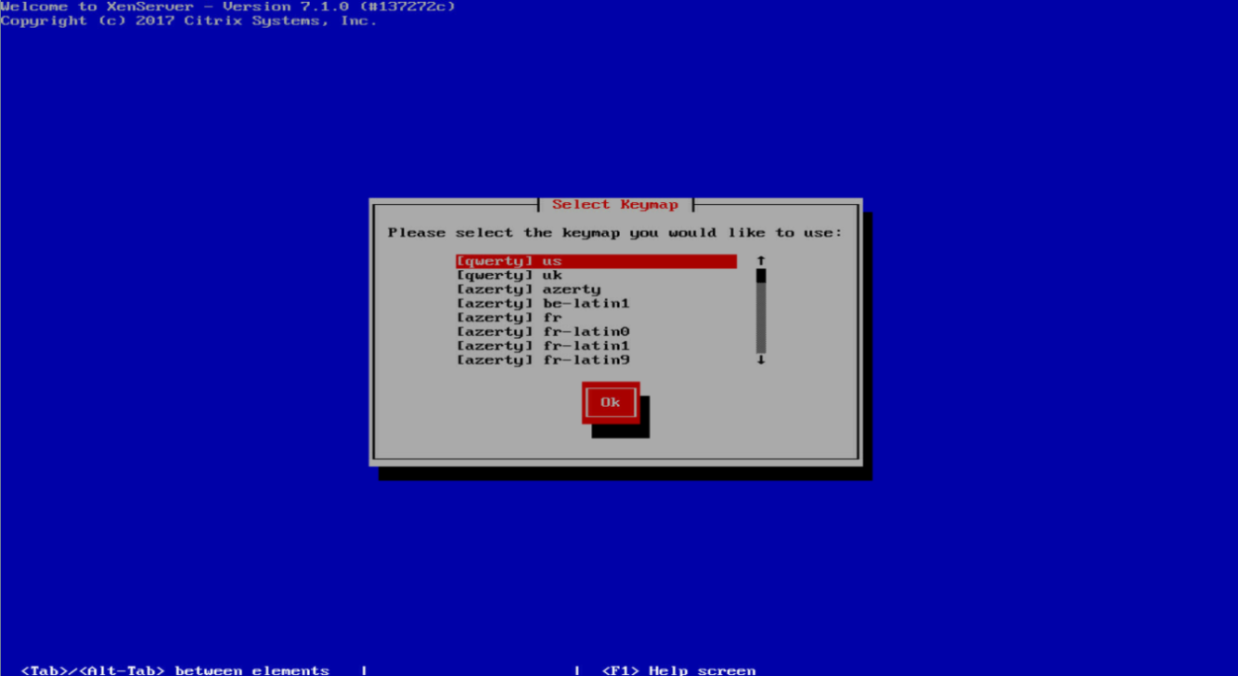
3. Select the keymap to use and then click OK. This example selects [qwerty] us.
Figure 117 Selecting the keymap
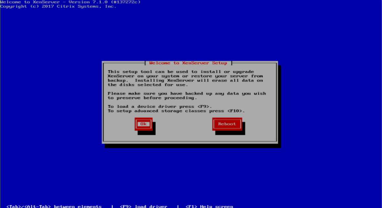
4. Confirm installation and then click OK.
Figure 118 Confirming installation
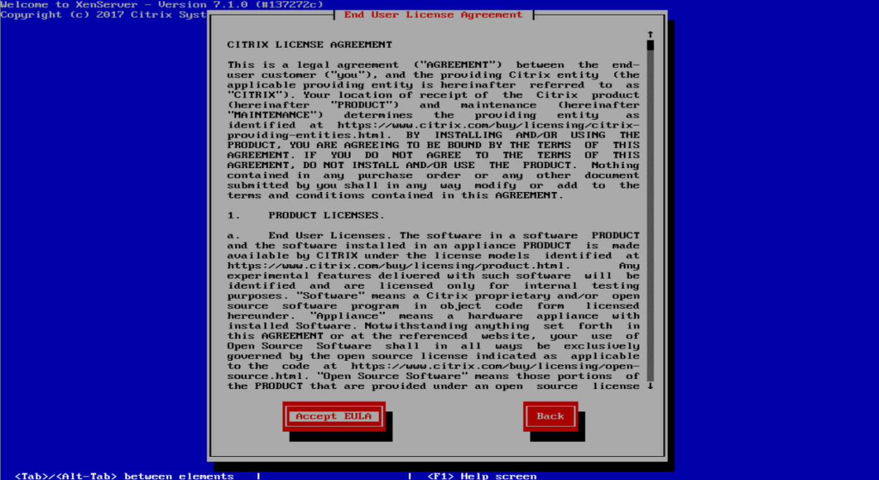
5. Read the End User License Agreement, select Accept EULA, and then press Enter.
Figure 119 End User License Agreement
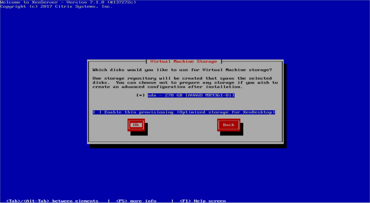
6. Select a disk to install the OS if you have multiple disks, and then click OK.
Figure 120 Selecting a disk
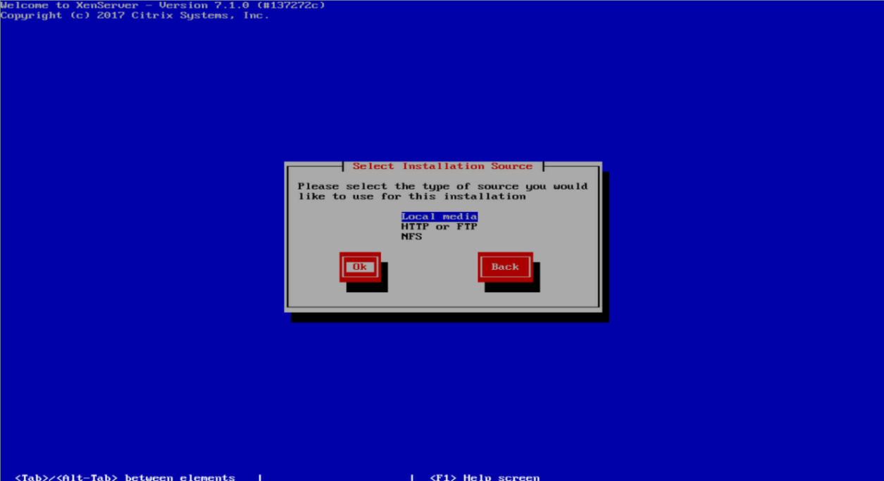
7. Select Local media as the installation source, and then click OK.
Figure 121 Selecting an installation source
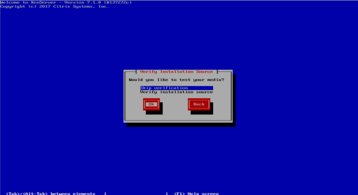
8. Select Skip verification, and then click OK.
If you encounter any issues during installation, verify the installation source as a best practice.
Figure 122 Verifying the installation source
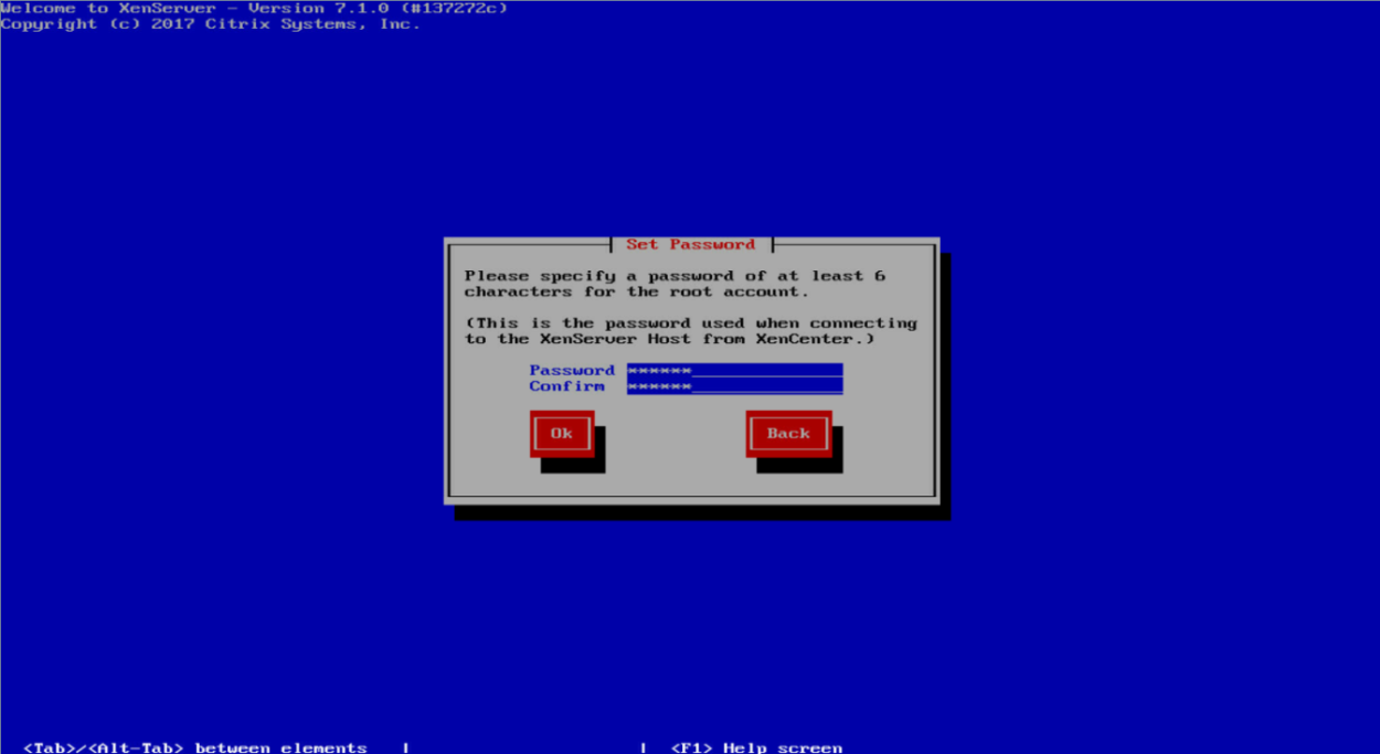
9. Set and confirm the root password, and then click OK. XenCenter will use this password to connect to the XenServer host.
Figure 123 Setting the root password
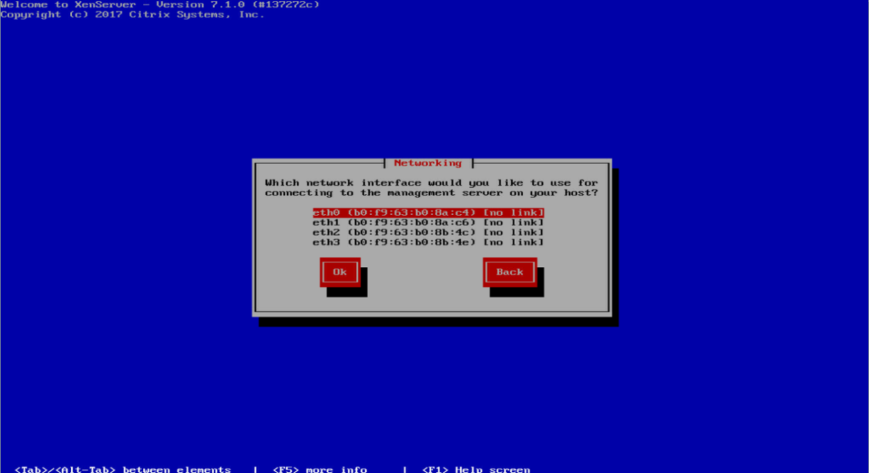
10. Select a network interface for connecting to the management server, and then click OK.
Figure 124 Selecting a network interface
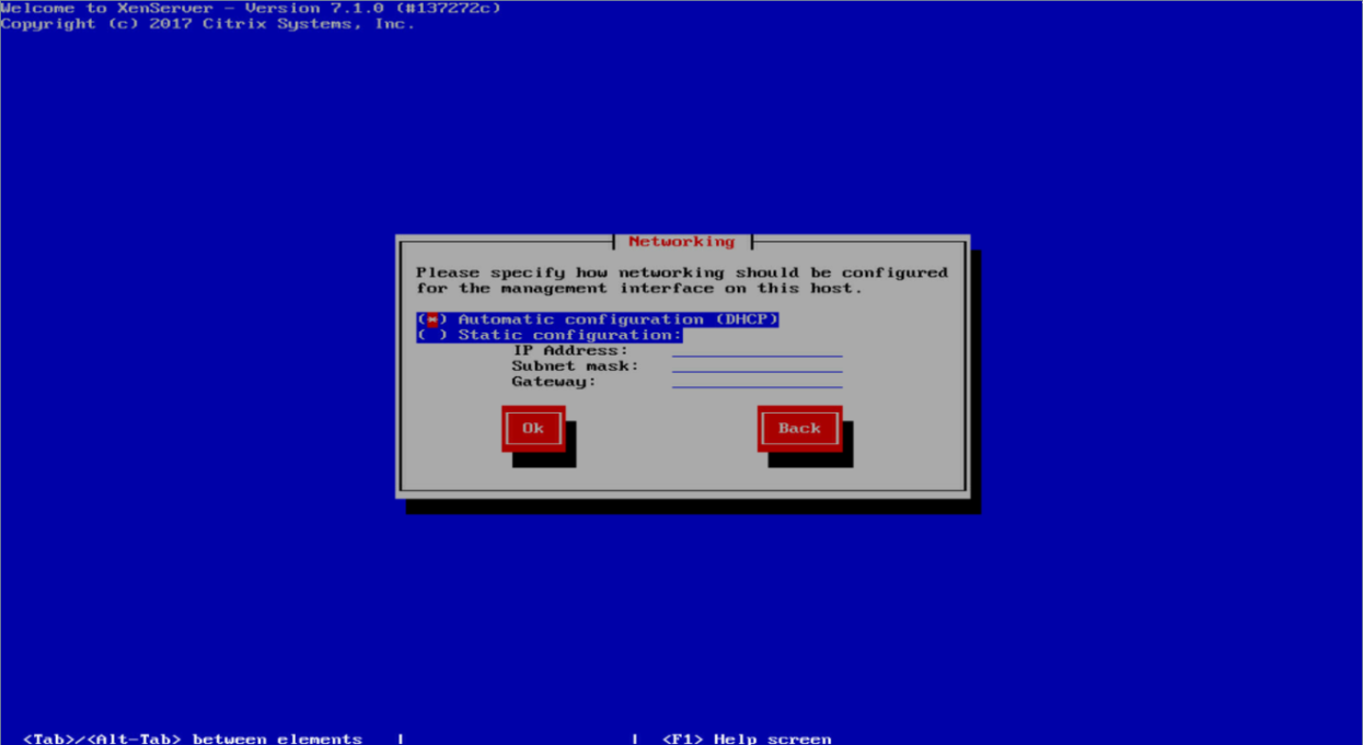
11. Select a method for specifying an IP address for the management interface, and then click OK.
¡ Automatic configuration (DHCP)—Obtains an IP address through DHCP.
¡ Static configuration—Manually specify an IP address. If you select this option, you must also specify an IP address, mask, and gateway address.
Figure 125 Specifying an IP address
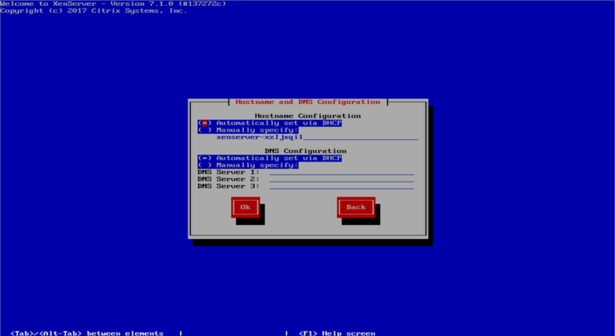
12. Configure DNS by using either of the following methods, and then click OK.
¡ Automatically set via DHCP.
¡ Manually specify. If you select this option, you must specify an IP address for a minimum of one DNS server.
Figure 126 Configuring DNS
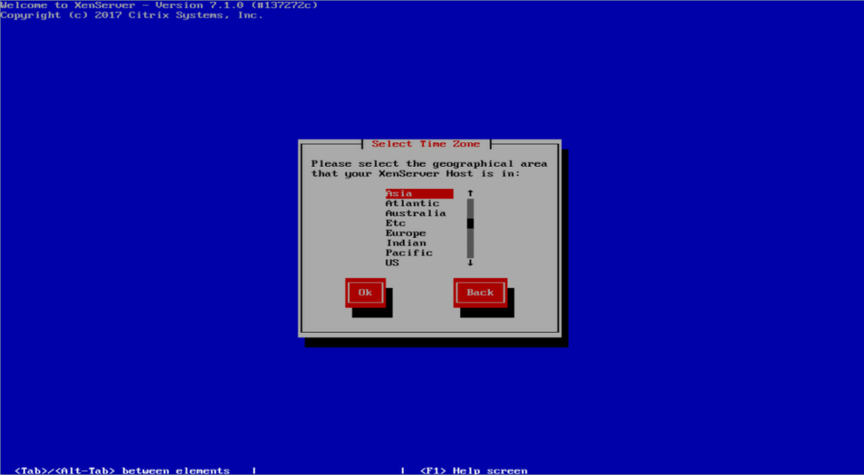
13. Set the time zone by selecting the geographical area and then the city, and then click OK.
Figure 127 Setting the time zone
14. Select a method for setting the system time, and then click OK.
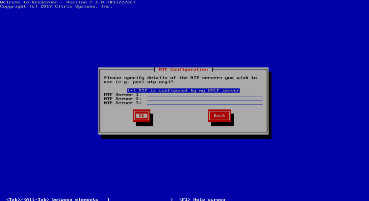
¡ Using NTP—You must specify a minimum of one NTP server and specify the IP address of the NTP server.
¡ Manual time entry—You must manually enter the system time after installation.
Figure 128 Selecting the method for setting the system time
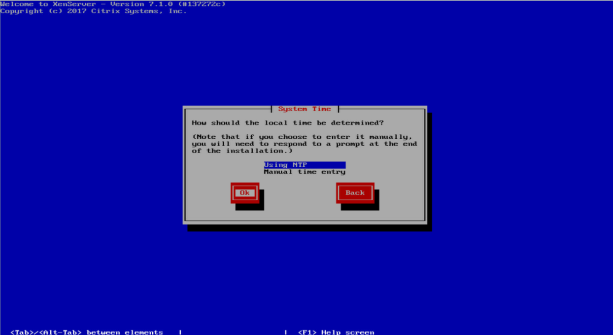
Figure 129 Configuring the NTP server
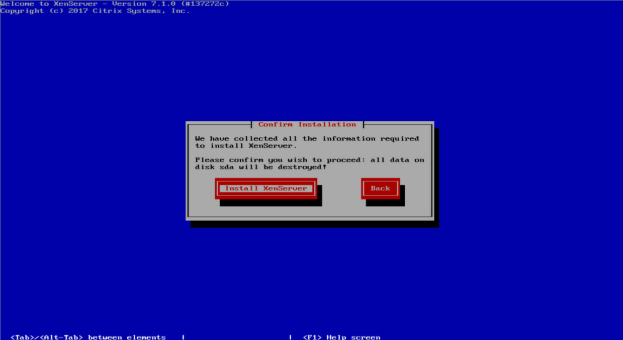
15. Select Install XenServer, and then press Enter to start installation.
Figure 130 Starting installation
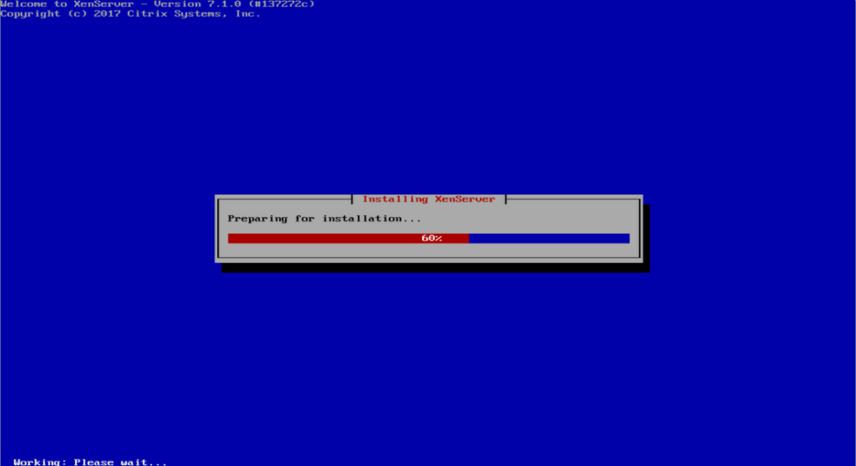
16. Wait for the system to complete installation.
Figure 131 OS installation in progress
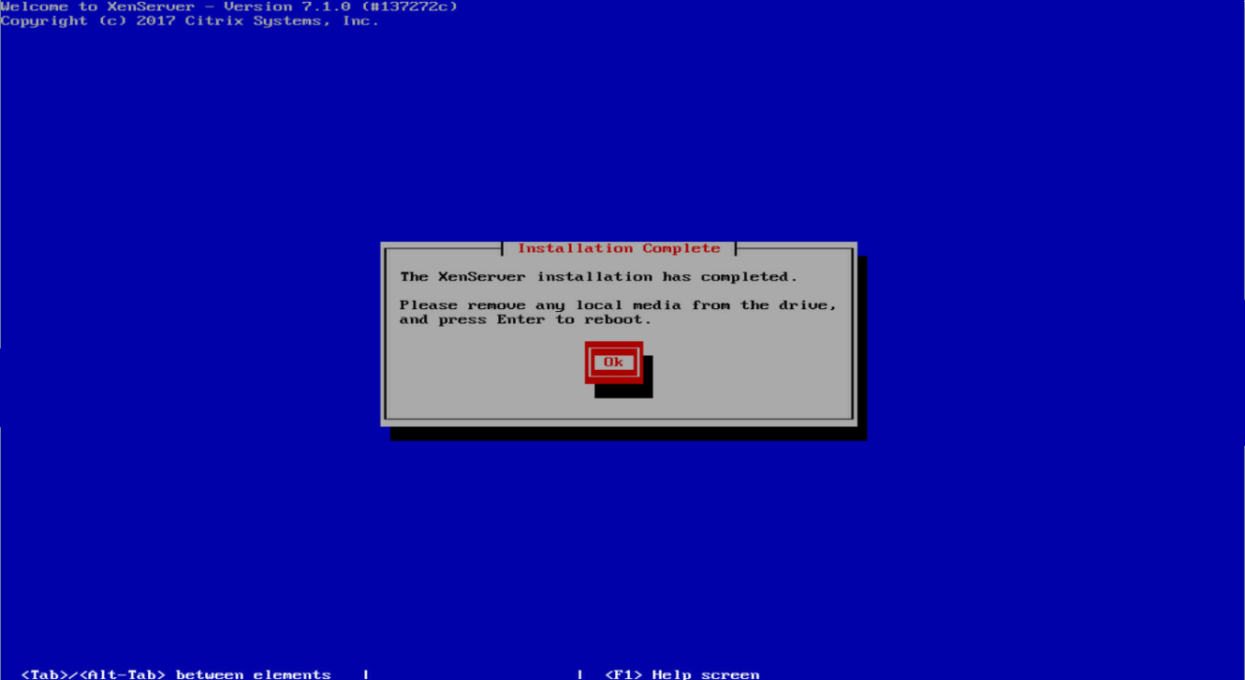
17. Click OK after installation is completed to restart the server.
Figure 132 Installation completed
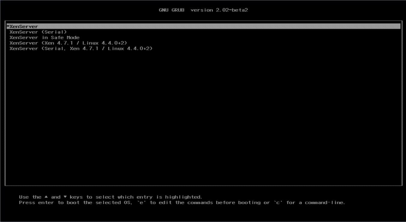
18. Select XenServer, and then press Enter.
Figure 133 GNU GRUB
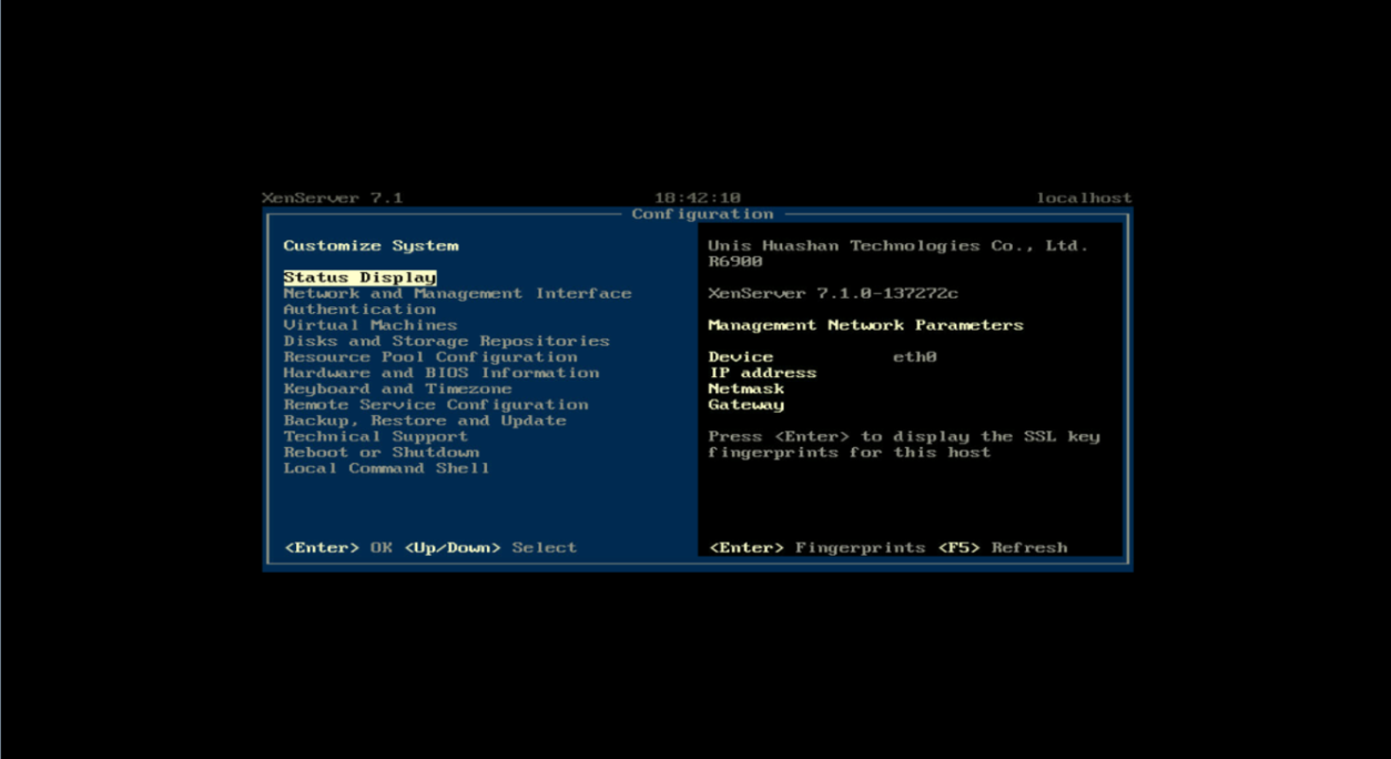
You have entered the Citrix XenServer GUI when the following page appears.
Figure 134 Citrix 7.1 GUI
|
|
NOTE: If a storage controller has been installed on the server, install the driver for the storage controller as shown in "Installing a storage controller driver by using an .rpm file (for RedHat OSs)"as a best practice. |
Installing a Ubuntu OS
The installation procedures are similar for different Ubuntu OS versions. This example installs Ubuntu 14.10 and the storage controller driver.
Make sure both the OS image and the storage controller driver file have been mounted to the server.
Restrictions and guidelines
Install the RAID controller driver package by following the procedures in the Readme packed with the RAID controller driver package obtained from the H3C official website.
If the system displays that the driver name is in use when you remove the driver shipped with the kernel by executing the modpobe –r driver_name or rmmod driver_name command, it indicates that the hard drive connected to the storage controller has the system disk where the controller is created. In this case, do not remove the driver until you are prompted or reboot the server and then enter the BIOS Setup Utility to delete the original logical disk, create a new disk and then continue installation.
Procedure
1. Enter the BIOS and select boot options. For more information, see "Selecting the boot media."
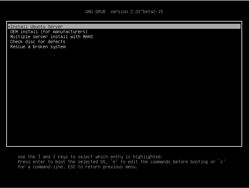
2. Select Install Ubuntu Server, and then press Enter.
Figure 135 Installing Ubuntu server
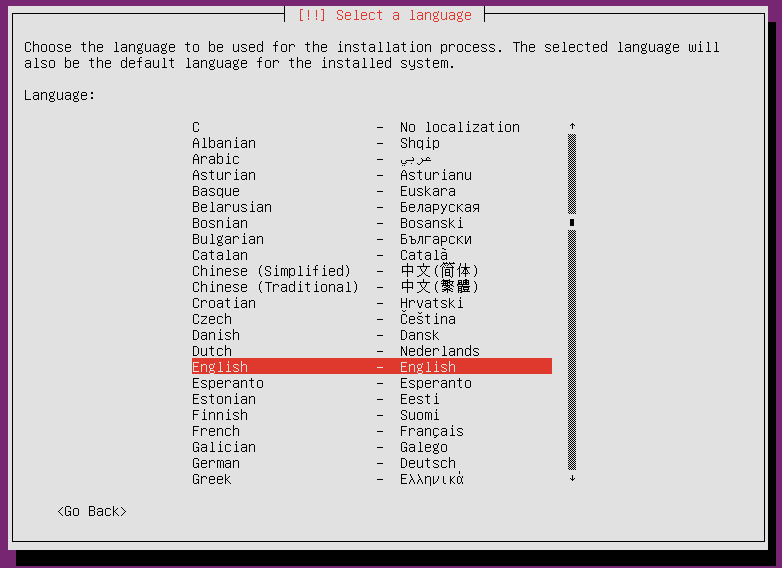
3. Select a language, and then press Enter.
Figure 136 Selecting a language
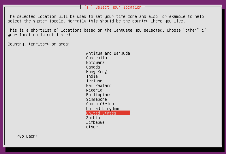
4. Select your location, and then press Enter.
Figure 137 Selecting a location
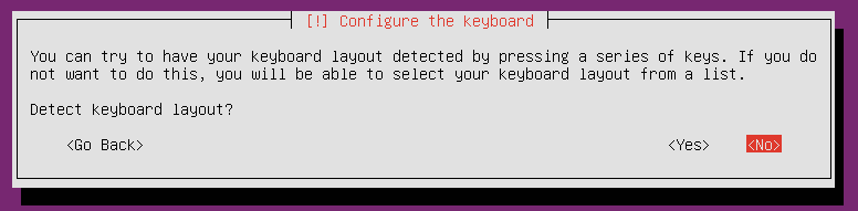
5. Select whether to detect keyboard layout. This example skips keyboard layout detection.
Figure 138 Selecting whether to detect keyboard layout
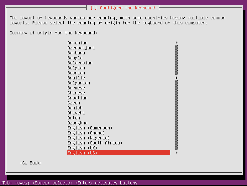
6. Select the country of origin for the keyboard, and then press Enter.
Figure 139 Selecting the country of origin for the keyboard
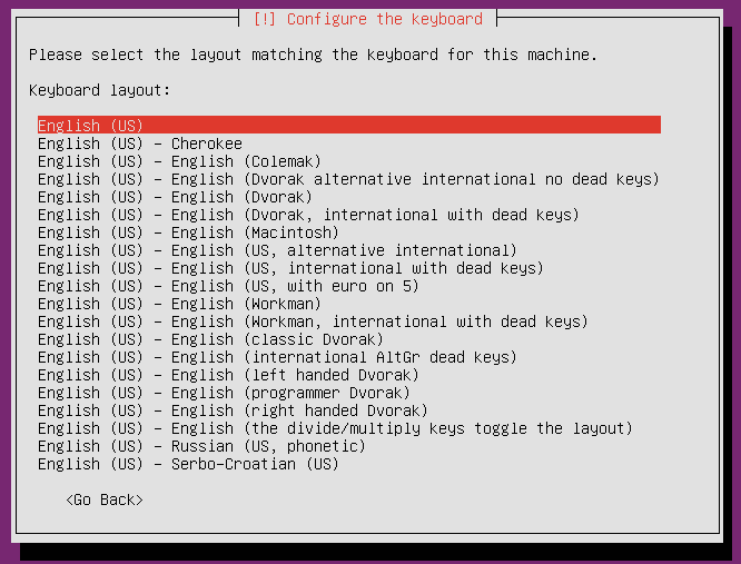
7. Select the keyboard layout, and then press Enter.
Figure 140 Selecting the keyboard layout
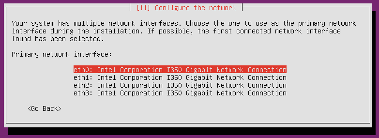
8. Select a connected network interface as the primary network interface, and then press Enter.
Figure 141 Configuring the network
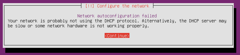
9. Press Enter when the following page appears.
Figure 142 Network autoconfiguration failed
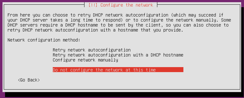
10. Select a network configuration method, and then press Enter. This example selects not to configure the network at this time.
Figure 143 Selecting a network configuration method
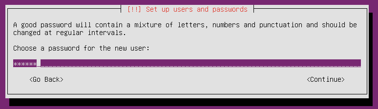
11. Enter the host name and set the user and password in turn by following the configuration wizard, as shown in the following figures.
Figure 144 Entering the host name
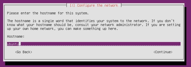
Figure 145 Entering the real name of the user
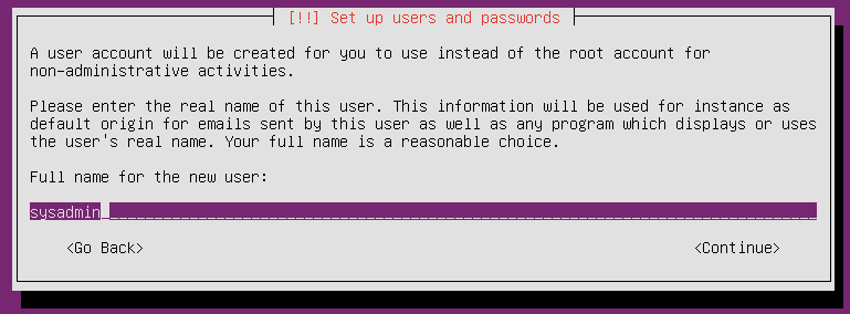
Figure 146 Entering the username for your account
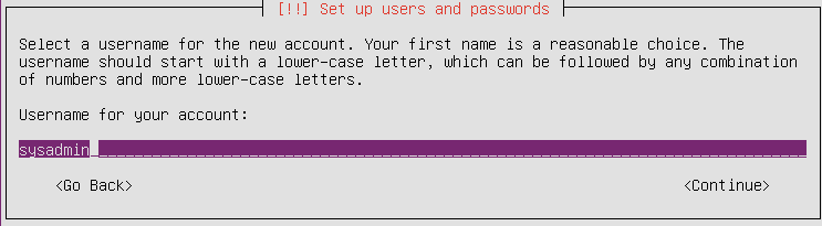
Figure 147 Setting the password
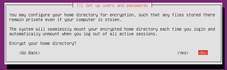
12. Configure whether to encrypt your home directory. This example selects to not encrypt the home directory.
Figure 148 Setting home directory encryption
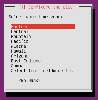
13. Select the time zone, and then press Enter.
Figure 149 Selecting the time zone
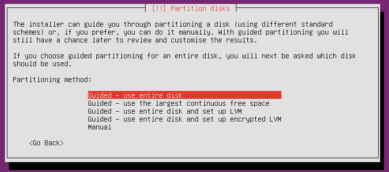
14. Select a partitioning method. This example selects Guided - use entire disk.
In UEFI boot mode, to avoid installation failure, you must create the /boot/efi partition, and make sure the files in the partition are in the efi or fat format if you select manual partitioning.
In Legacy mode, if you select Guided - use entire disk, the system creates only the / and swap partitions. You must click no to return to the / partition and then set the bootable flag to on, or create the /boot partition, and then set the bootable flag of the partition to on.
Figure 150 Selecting a partitioning method
15. Check the partitions, and then select Yes. The system will automatically divide the disk into three partitions.
Figure 151 Checking the partitions
16. Wait for the system to complete installation.
Figure 152 Installing the system

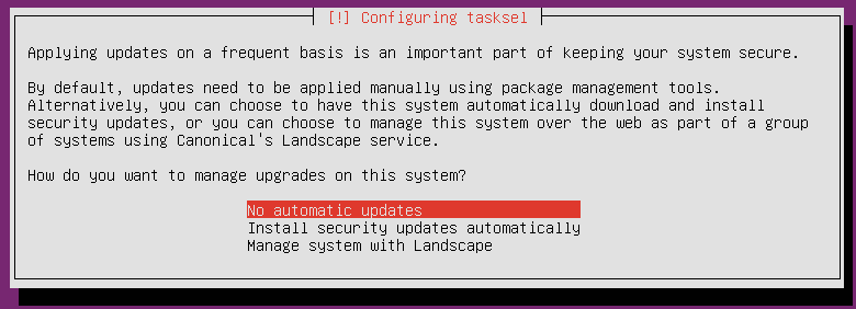
17. Select a method for applying updates. This example selects to not update the system.
Figure 153 Selecting a method for applying updates
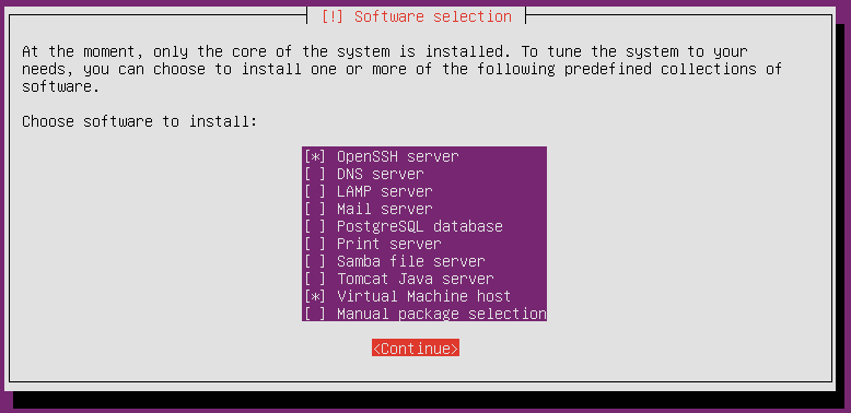
18. Choose software to install. This example selects OpenSSH server and Virtual Machine host.
If you select Manual package selection, you must manually select the package to install.
a. Press ↑ or ↓ to select target software.
b. Press Space to confirm your selection.
c. Press Tab to move your cursor to Continue, and then press Enter.
Figure 154 Choosing software to install
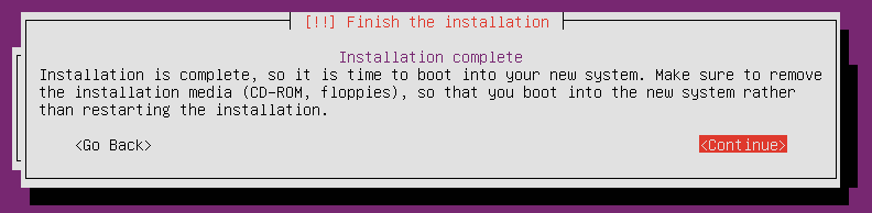
19. Press Enter when the following page appears to complete installation.
Figure 155 Finishing the installation
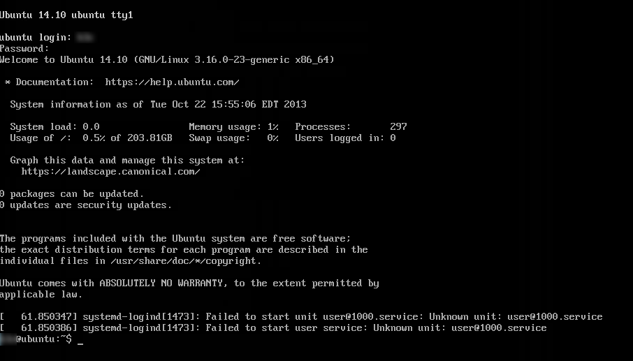
20. Enter the username and password to log in to Ubuntu.
Figure 156 Entering the username and password
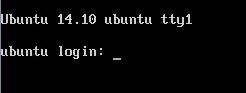
Figure 157 Logging in to the Ubuntu OS
Installing an Oracle Linux 8.2 OS
Oracle Linux 8.2 OS was released based on Red Hat Enterprise Linux 8.2 OS and provides some new features. It comes with drivers and does not require manual driver installation.
To install an Oracle Linux 8.2 OS:
1. Enter the BIOS and select boot options. For more information, see "Selecting the boot media."
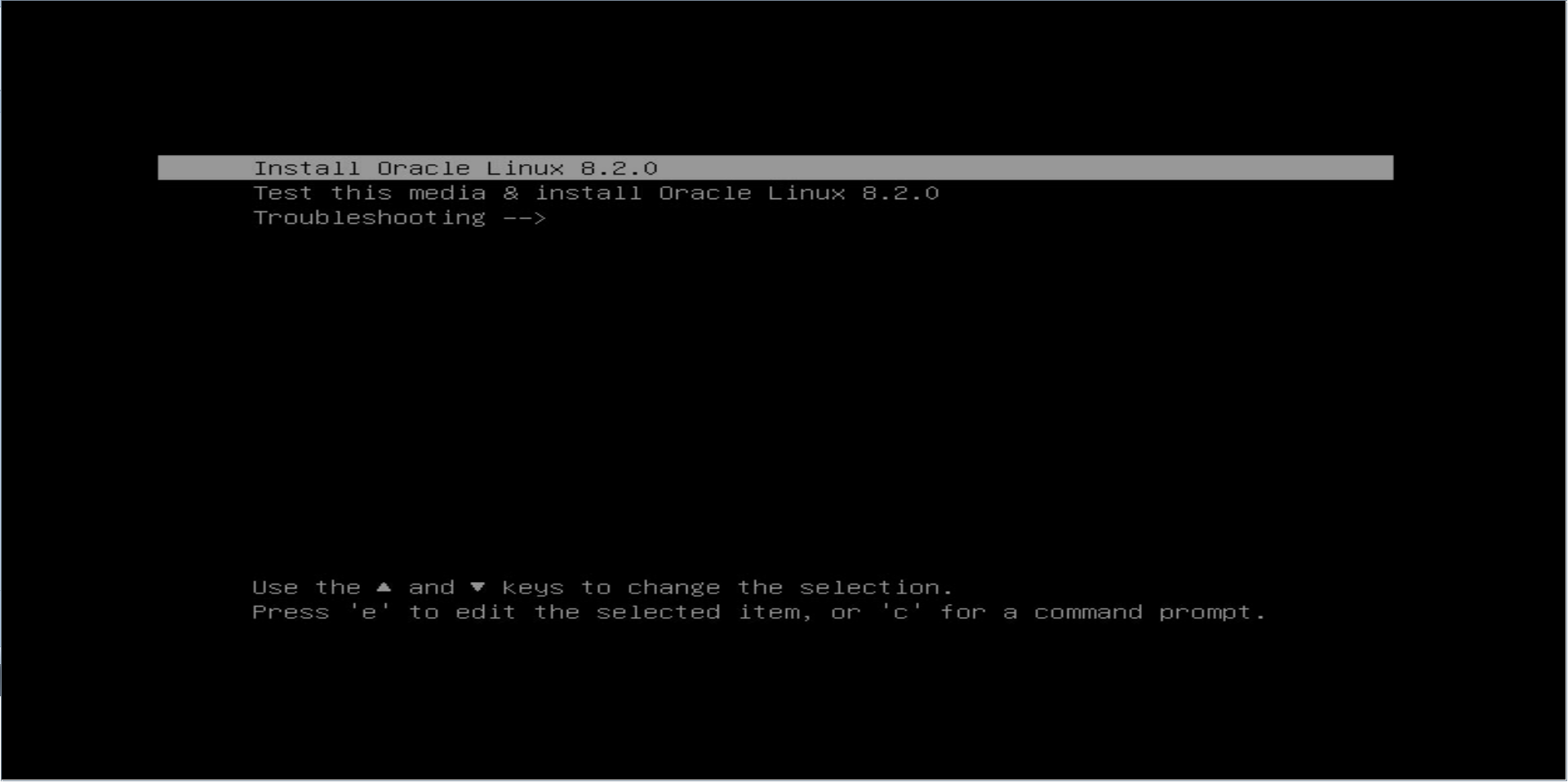
2. As shown in Figure 157, select Install Oracle Linux 8.2.0, and then press Enter.
The deployment screen appears as shown in Figure 158.
Figure 158 Confirming OS installation
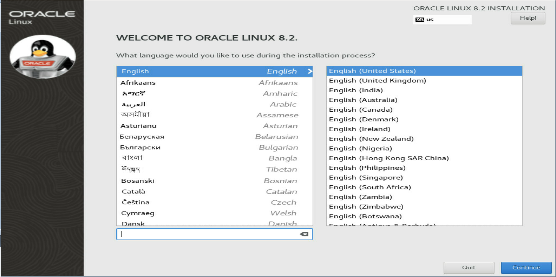
3. Select the language, and then click Continue.
Figure 160 Selecting the language
4. On the INSTALLATION SUMMARY page that opens, configure the system information, including the installation destination, network name, and host name.
Figure 161 Configuring system information
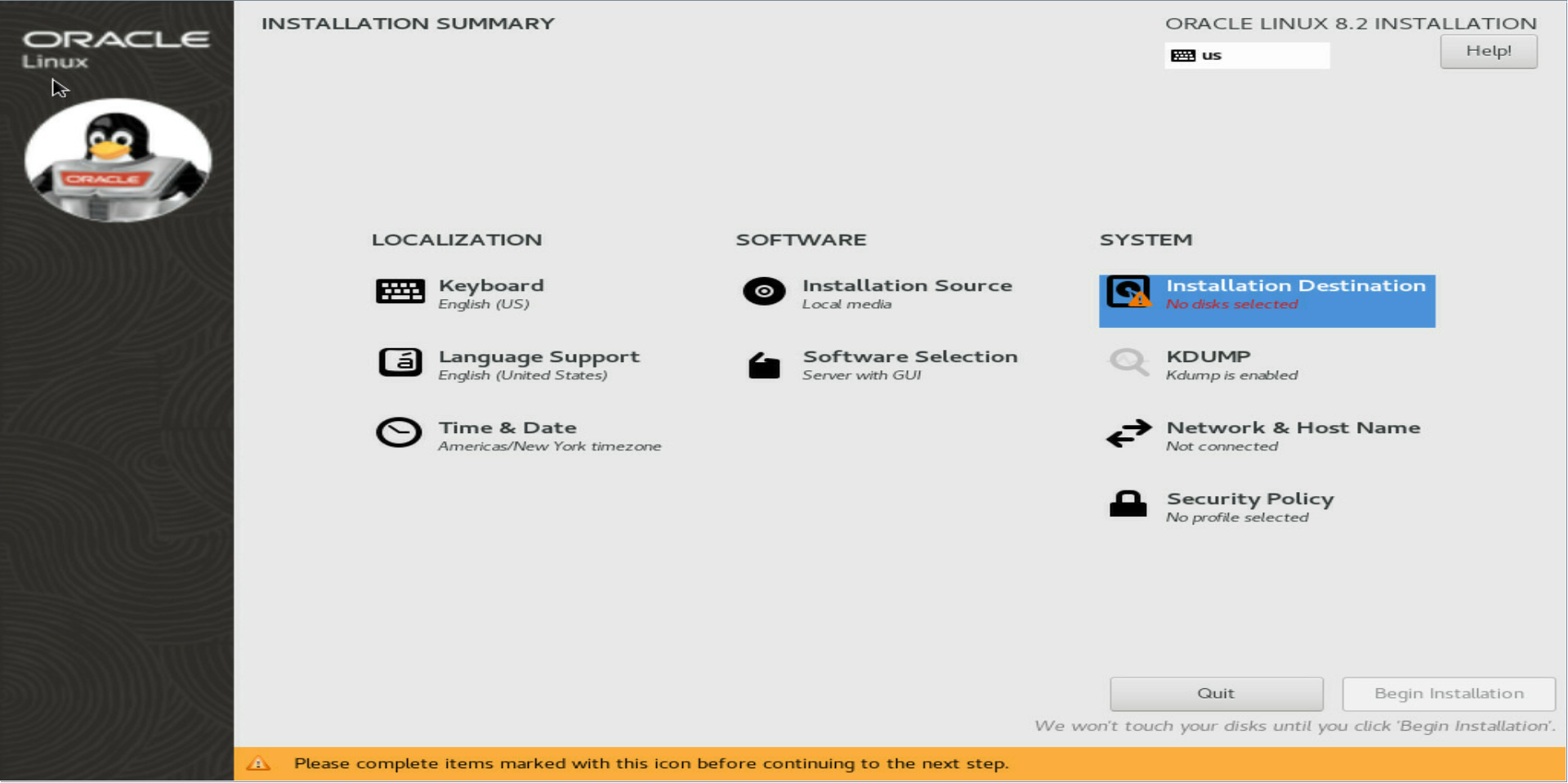
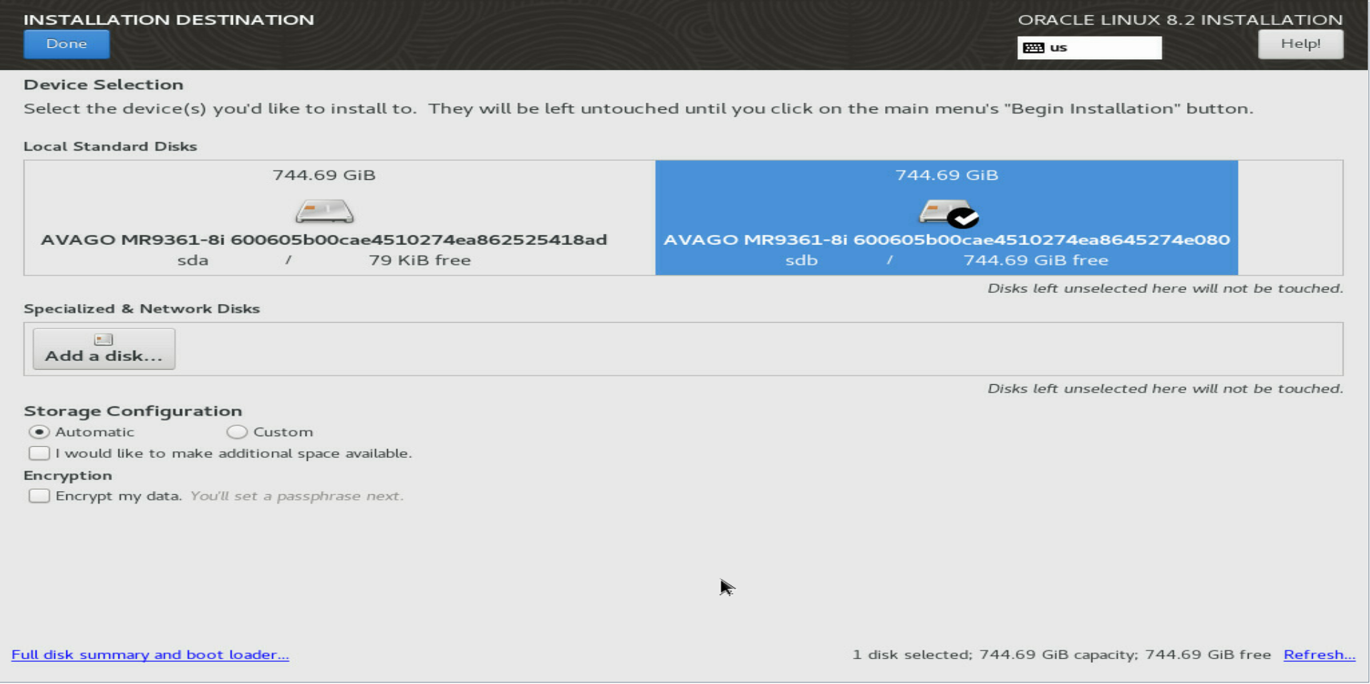
a. In the SYSTEM area of the INSTALLATION SUMMARY page, click Installation Destination. On the page that opens, select the destination devices, select a storage configuration, select whether to encrypt the data, and then click Done.
Figure 162 Configuring the installation destination
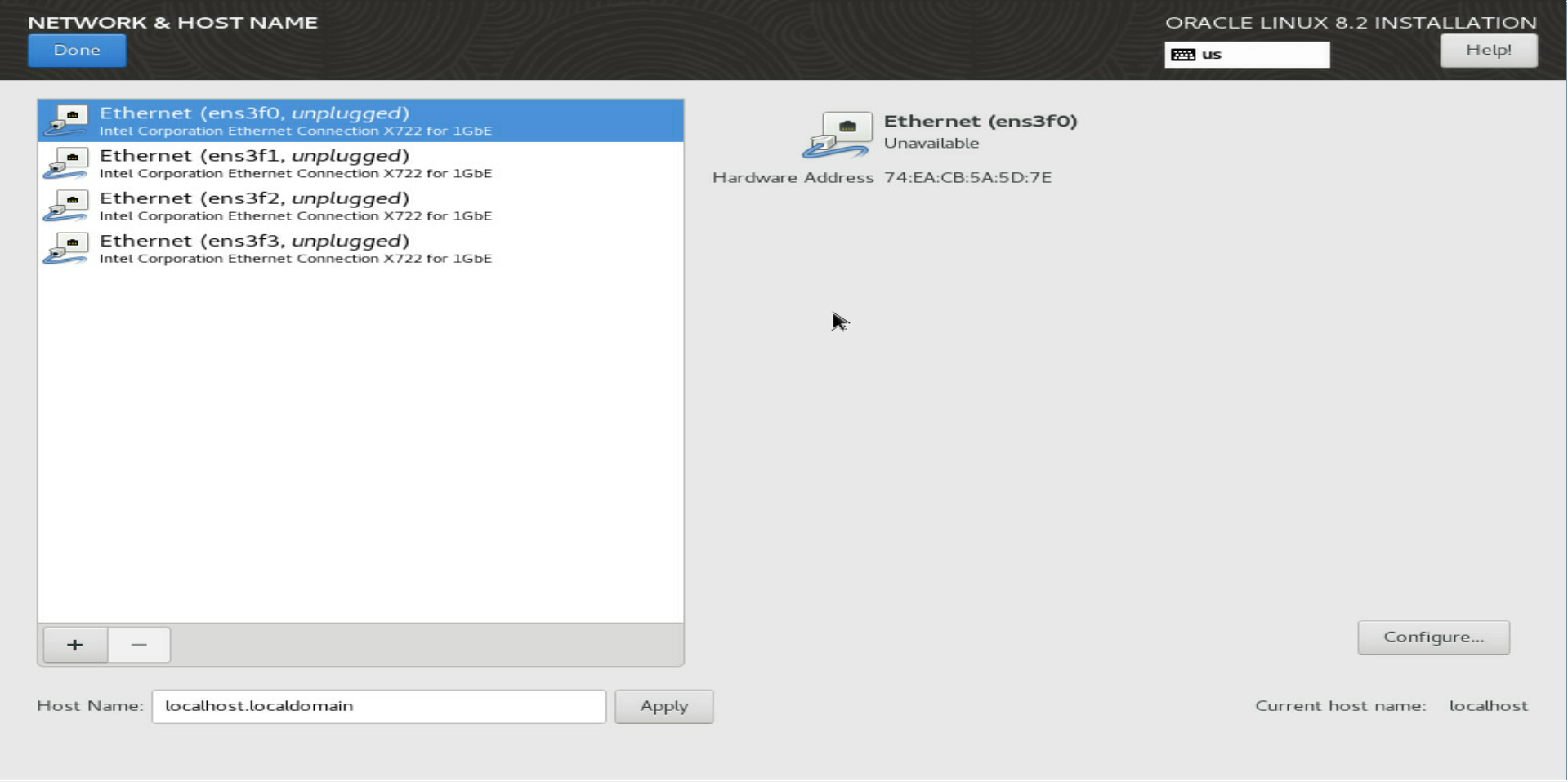
b. In the SYSTEM area of the INSTALLATION SUMMARY page, click Network & Host Name. On the page that opens, select a network port, specify a host name, and then click Done.
Figure 163 Configuring the network name and host name
5. On the INSTALLATION SUMMARY page, click Begin Installation.
The OS installation process might take a long time.
Figure 164 Installation progress
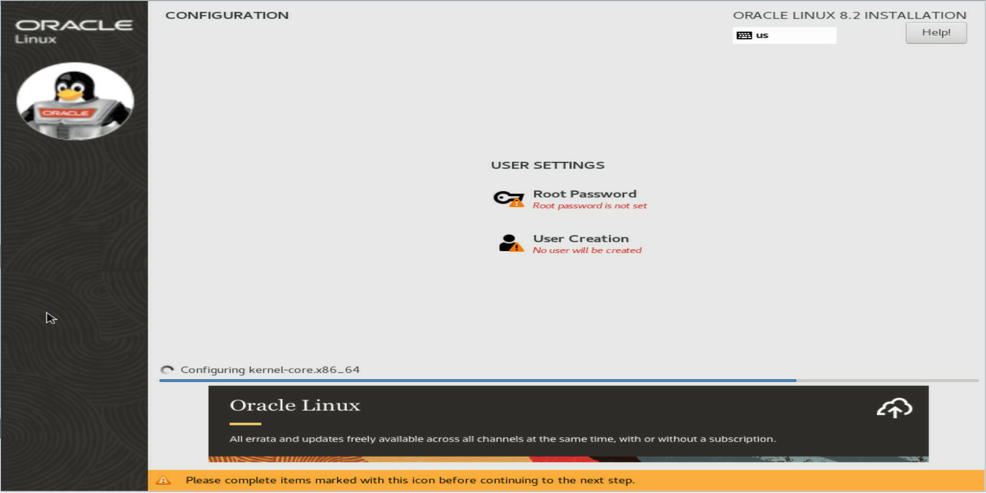
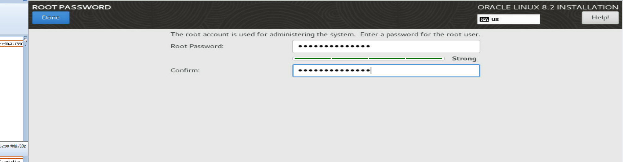
6. After the installation finishes, click Root Password on the CONFIGURATION page to set the root password and click Done.
As a best practice, specify a strong password.
Figure 165 Setting the root password
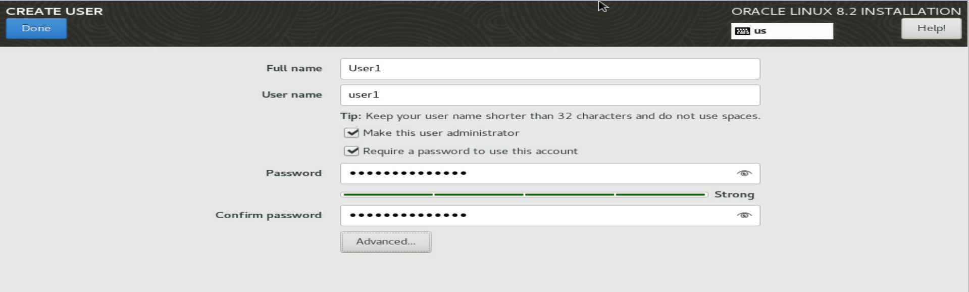
7. On the CONFIGURATION page, click User Creation to configure a user, and then click Done.
Figure 166 Creating a user
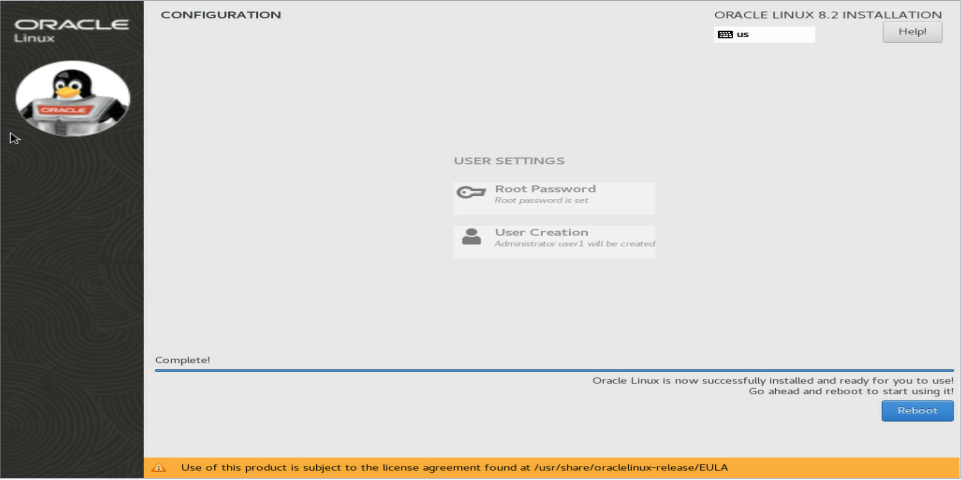
8. On the CONFIGURATION page, click Finish Configuration, and then click Reboot to reboot the server.
Figure 167 Rebooting the server
9. On the login page that opens, enter the password to sign in to the OS.
Figure 168 Entering the password
After a successful login, you are placed on the welcome page as shown in Figure 168.
Installing a CAS OS
For more information about how to install a CAS OS, see the installation guide for H3C CAS.
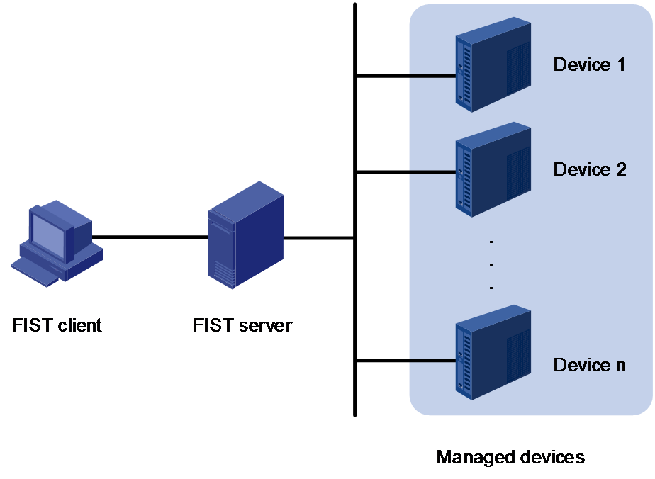
Installing an OS and drivers through FIST
To install an OS on multiple servers in bulk, configure a server template that defines OS settings and drivers from FIST, and then apply the server template to the servers.
For information about server templates and OS types supporting installation through FIST, see the FIST user guide.
Preparing for installation
Setting up the FIST environment
For information about how to set up the FIST environment, see the FIST installation guide.
Preparing an OS image
Before installing an OS, obtain the OS image in .iso format from the official website of the OS, and save the OS image to the FIST client.
To install a VMware ESXi OS through FIST, obtain the customized OS image from the H3C official website.
Preparing a REPO file
Before installing an OS, obtain the compatible REPO file from the H3C official website. For more information, see H3C Servers REPO User Guide.
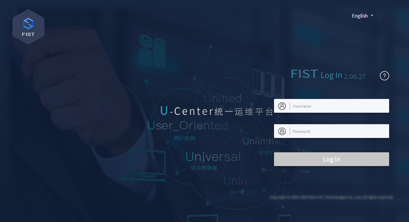
Signing in to FIST
Restrictions and guidelines
You can only use user accounts in Activated state to log in to FIST. Login requests with an inactivated account will be rejected.
Procedure
1. Open the browser, enter the system IP address of the FIST server in the format of https://FIST_ip_address in the address bar, and then press Enter.
If you have changed the port number used by the FIST Web service, enter http://FIST_ip_address:port_number or http://localhost:port_number. http://localhost:port_number is available only on the FIST server.
2. On the sign-in page, enter the username and password, and then click Log In.
The default username and password are admin and Password@_, respectively.
Installing the OS
Add servers to FIST
Restrictions and guidelines
This section describes the procedure for adding one server to FIST. For information about adding multiple devices in bulk, see FIST online help.
The default HDM username and password are admin and Password@_, respectively.
Procedure
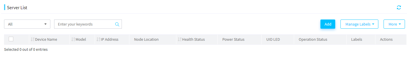
1. From the navigation bar, select Menu > Devices > Server List.
Figure 172 Entering the server list page
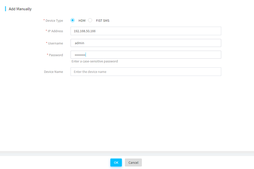
2. Click Add and select Add Manually in the Method dialog box that opens.
|
|
IMPORTANT: To add multiple servers in bulk, select Auto Discovery or Bulk import as a best practice. For more information, see the FIST user guide. |
3. Select HDM as the device type, enter the HDM management IP address, HDM username and password, and then click OK.
|
|
IMPORTANT: Make sure the HDM account specified by the username has the administrator role and the VMedia privilege. For more information about user privileges, see HDM online help. |
Upload an OS image
Restrictions and guidelines
· Make sure the name of the OS image, including the suffix, does not exceed 60 characters.
· To avoid uploading failure, make sure the OS image has a different name from the existing images.
· To avoid uploading failure, do not refresh the FIST webpage during the uploading process.
· To avoid OS installation errors, make sure the OS image is obtained from the official website and is not corrupt.
· Make sure the name of the OS image does not contain left angle brackets (<), right angle brackets (>), or quotation marks (").
Procedure
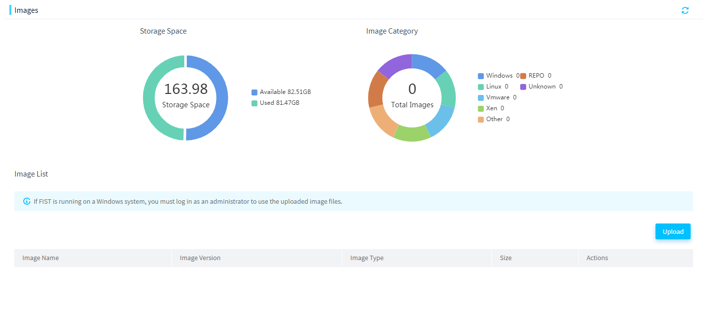
1. In the navigation pane, select Menu > Templates > Images.
Figure 174 Entering the Images page
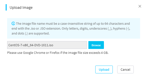
2. Click Upload.
3. In the dialog box that opens, click Browse to select an image file to upload, and then click Upload.
After the uploading, you can view the uploaded OS image in the Images page.
Figure 175 Uploading an OS image
Upload a REPO file
1. Select Menu > Templates > Repository to enter the Repository page.
Figure 176 Entering the Repository page
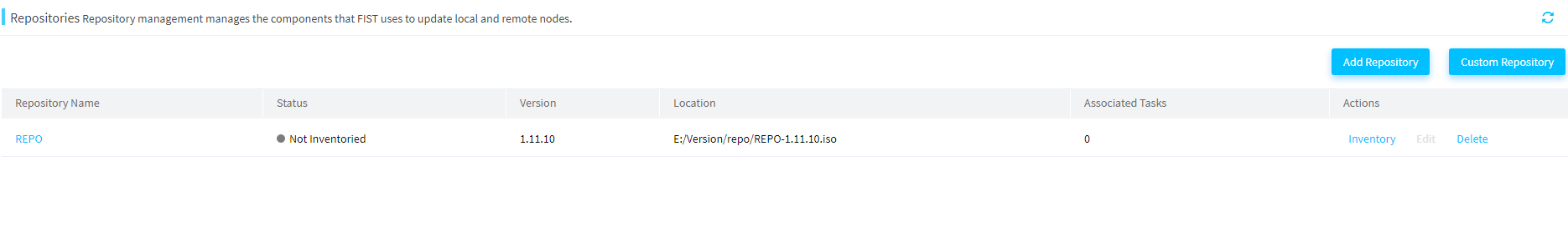
2. Click Add Repository. In the dialog box that opens, select a repository path. This document uses the local path as an example.
Figure 177 Adding a repository
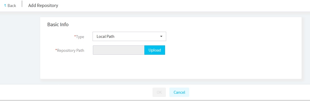
3. Click Upload. In the dialog box that opens, click Browse to select a repository to upload, and then click OK.
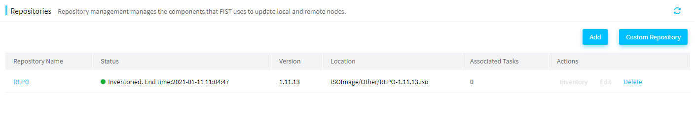
4. Click Inventory for the target repository. The system starts to inventory components.
|
|
NOTE: In FIST 2.00.22 or a later version, the system automatically inventories components after you add a repository. |
Figure 178 Inventory components
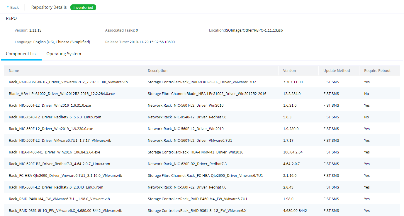
5. To view the check result, click the repository name.
Figure 179 Viewing the inventory result
Add a server template
Restrictions and guidelines
· Make sure the storage controllers to be configured are the same model as specified in the RAID settings. If two storage controllers are configured, make sure the storage controllers are present on the server.
· Make sure the member drives of RAID arrays are present and are operating correctly.
Procedure
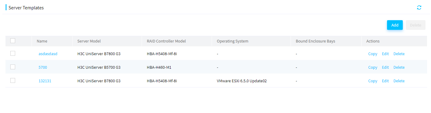
1. In the navigation pane, select Menu > Templates > Server Templates to enter the Server Templates page.
Figure 180 Server Templates page
2. Click Add.
Figure 181 Adding a server template
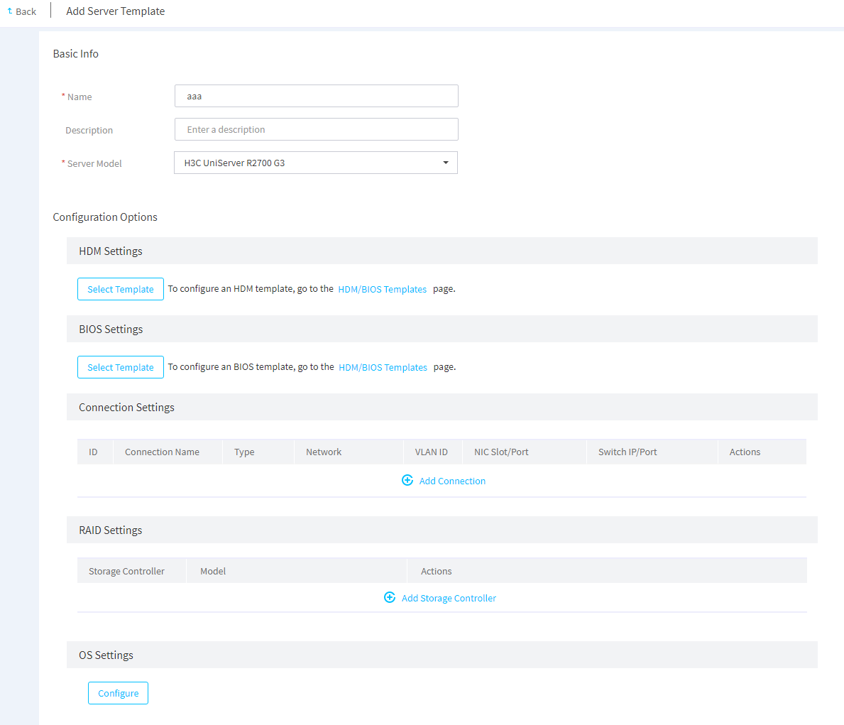
3. In the Basic Info area, enter the server template name and template description (optional), and then select a compatible server model from the Server Model list.
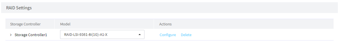
4. In the RAID Settings area, click Add Storage Controller, select the storage controller model, and then click Configure.
FIST supports managing only LSI controllers in RAID mode.
Figure 182 Adding a storage controller
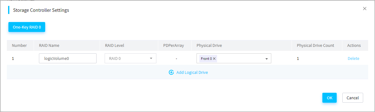
5. On the dialog box that opens, enter RAID name, RAID level, select a physical drive, and then click OK.
|
|
IMPORTANT: To avoid OS installation failure, do not install an OS through a template on a drive of 2 TB or a larger capacity as a best practice. |
Figure 183 Configuring a logical drive
6. In the OS Settings area, click Configure.
7. On the OS Settings page that opens, select an operating system and an image file. See Figure 183.
Figure 184 Configuring system settings
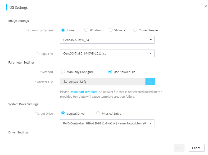
8. Select a method in the Parameter Settings area.
a. If you select Use Answer File, click Download Template to obtain the answer file template for the system. Modify the answer file template as needed, and click the … icon next to Answer File to upload the answer file.
|
|
IMPORTANT: · The Use Answer File method is available only for a RedHat or CentOS OS. · As a best practice to ensure template creation success, download the answer file template instead of create a one yourself. For information about the format requirements and usage of the answer file, see the guidelines and the readme file in the template. |
Figure 185 Configuring an OS by using an answer file

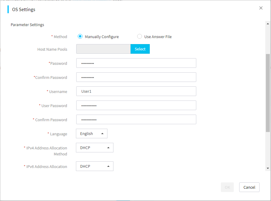
b. If you select Manually Configure, configure OS-related parameters.
The available parameters vary by OS type. This document uses a Linux OS for example.
Figure 186 Manually configuring an OS
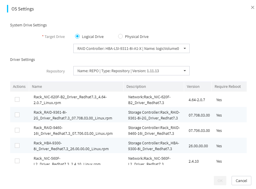
9. Select a target drive in the System Drive Settings area and select a repository in the Driver Settings area.
If you need to install a driver, select the driver file from the repository library.
Figure 187 Selecting the target drive and repository
10. Click OK.
Figure 188 Confirming OS settings
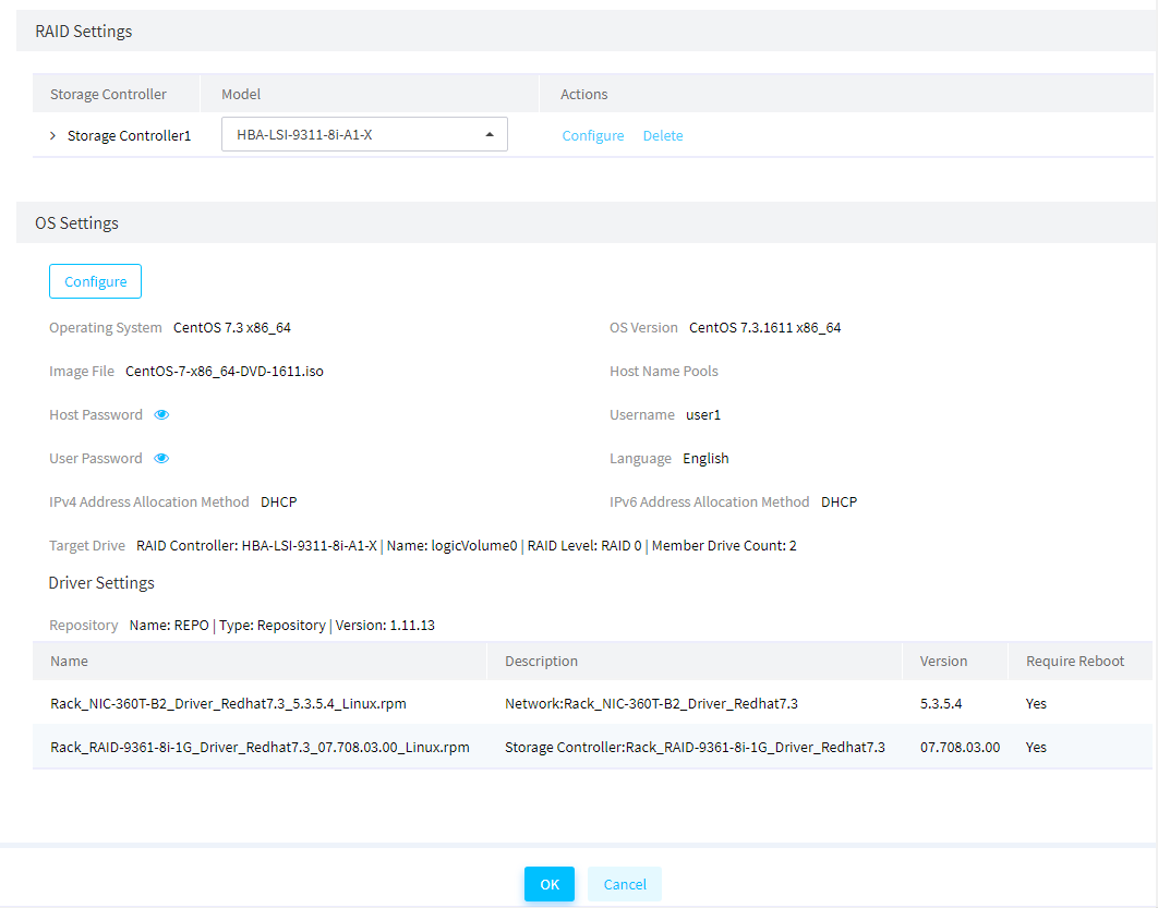
11. Confirm OS settings and then click OK.
Apply a server template for OS installation
Restrictions and guidelines
· To complete RAID, system, and driver settings in a server template, you must install iFIST of the most recent version on the managed servers, and make sure iFIST has a system IP address that can communicate with FIST.
· To prevent template applications from affecting operations in the system, make sure the servers are shut down before applying the template to the servers.
· Before applying a template to servers, make sure no operations related to the template settings are in progress on the servers.
· Make sure the server model, BIOS version, HDM version, and hardware configuration of the target server are the same as the settings in the server template.
· During the template application process on a server, do not power off or reboot the server. The template application process might take a long time.
· During the template application process, do not use KVM to perform mount operations.
· Before driver installation, make sure the repository file specified during template configuration has been uploaded to FIST. Make sure the server is installed with PCIe devices specified in the driver settings of the server template and can obtain PCIe device information from HDM.
· During the template application process, the system installs the OS and drivers automatically.
Prerequisites
As a best practice, update iFIST of the target server to the latest version, because this feature will use the storage controller driver integrated in iFIST.
Procedure
1. In the navigation pane, select Menu > Deployment > Servers > Apply Server Templates.
Figure 189 Applying server templates
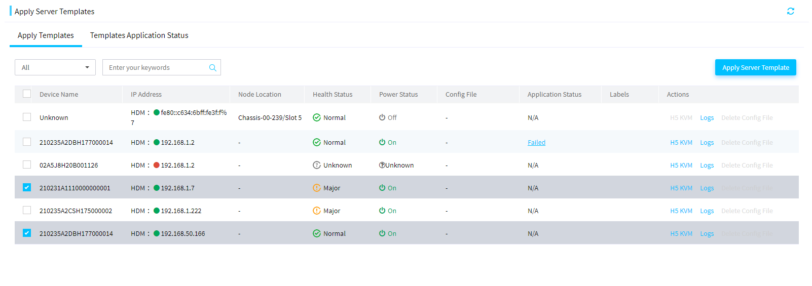
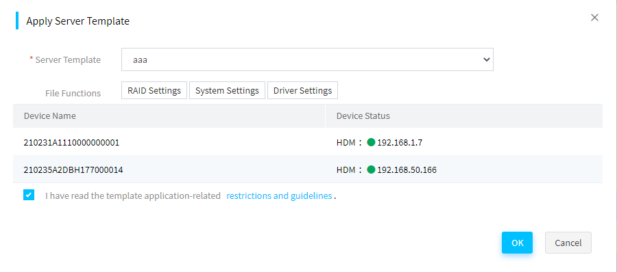
2. Select the target servers, and then click Apply Server Template.
3. In the dialog box that opens, select the server template to apply, select I have read the template application-related Message, and then click OK.
The Templates Application Status page opens and you can view the OS installation progress in the Application Status column.
Figure 190 Applying a server template
Installing an OS and drivers through iFIST
The integrated Fast Intelligent Scalable Toolkit (iFIST) is a single-server management tool embedded in H3C servers and provides the graphical OS installation wizard to reduce operation complexity. During OS installation, the drivers can be installed simultaneously if you have mounted the REPO to the server. For more information about REPO, see H3C Servers REPO User Guide. For more information about OS types supported by iFIST, see H3C Servers iFIST User Guide.
Preparing for installation
Supported operating systems
For more information, see H3C Servers iFIST User Guide.
Preparing an OS image
Before installing an OS, obtain an OS image from the official website of the OS, and then connect the boot media that contain the OS image to the server. You can use an optical disk drive, bootable USB disk, or virtual media as the boot media.
Preparing a REPO file
Before installing an OS, obtain the compatible REPO file from the H3C official website. For more information, see H3C Servers REPO User Guide.
Signing in to iFIST
Start the server, and press F10 on the POST screen as instructed.
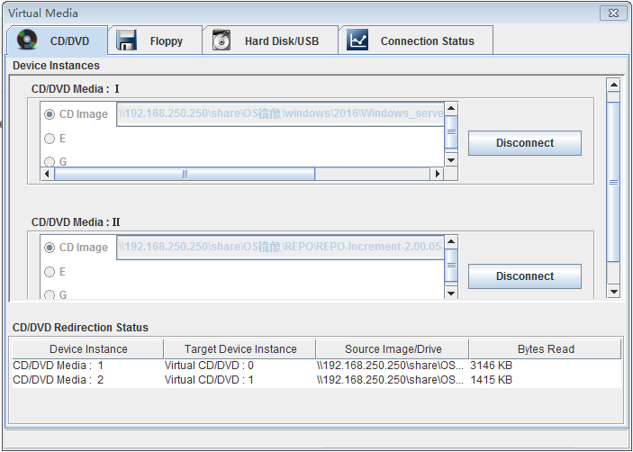
Mounting an OS image and REPO file
You can mount an OS image to the server through virtual media or a bootable USB disk. For more information, see "Connecting the OS image." The following procedure uses virtual media to mount an OS image and REPO file to the server.
To mount an OS image and REPO file:
1. Log in to HDM and launch a KVM remote console.
2. Select VMedia > Virtual Media Wizard.
The virtual media wizard opens.
3. On the CD/DVD tab that opens, click Browse and select an OS image and REPO file. Click Connect.
Figure 191 Mounting the OS image and REPO file
Installing the OS
Restrictions and guidelines
· The firewall of the OS installed through iFIST is disabled by default.
· When you install a new OS on the local server with an OS, the old OS will be overwritten.
· To avoid OS installation or startup failure, if you change the storage controller mode to HBA in Legacy mode, you must specify the first physical drive as the first boot option.
· To install an OS on a server in UEFI boot mode, make sure only the system disk contains a UEFI partition. OS installation might fail if a UEFI partition exists on a non-system disk.
· To avoid OS installation failure, do not install the OS on a drive of 2 TB or a larger capacity as a best practice.
· Before OS installation, make sure only one OS image is mounted to the server. If more than one bootable media are mounted, the server might fail to identify the correct boot media, and OS installation might fail as a result.
· If a USB disk is the boot media, the file name and path name of the OS image must meet the following requirements:
¡ Contain only letters, digits, hyphens (-), underscores (_), dots (.), and spaces.
¡ Do not contain consecutive spaces.
· If a USB disk as the boot media is removed and re-installed, refresh the webpage for the system to identify the boot media.
· Do not remove the boot media before the OS installation is complete.
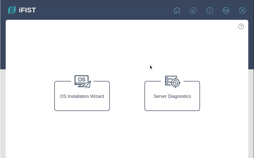
Procedure
1. On the iFIST Web interface, click OS Installation Wizard.
Figure 192 Selecting OS installation wizard
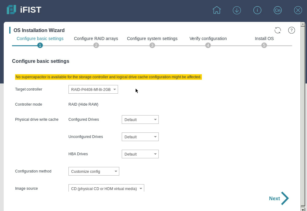
2. On the Configure basic settings page that opens, select the type of media as the boot media, and then click Next.
Figure 193 Configuring basic settings
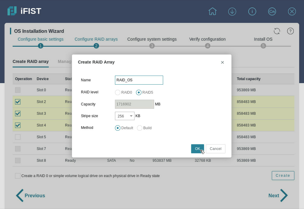
3. On the Configure RAID arrays page that opens, click the Create RAID array tab.
4. To create a RAID array:
a. Select physical drives as needed.
b. Click Create.
c. In the dialog box that opens, enter a RAID array name, select a RAID level, and then click OK.
Figure 194 Creating a RAID array
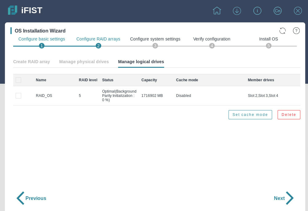
5. To view the logical drives on the server, click the Manage logical drives tab, and then click Next.
Before going to next step, iFIST examines if the OS image is mounted successfully and is supported. Otherwise, a prompt message appears and the system terminates the installation process.
Figure 195 Viewing logical drives
6. On the Configure system settings page, select drivers and configure the OS parameters.
Figure 196 Configuring system settings
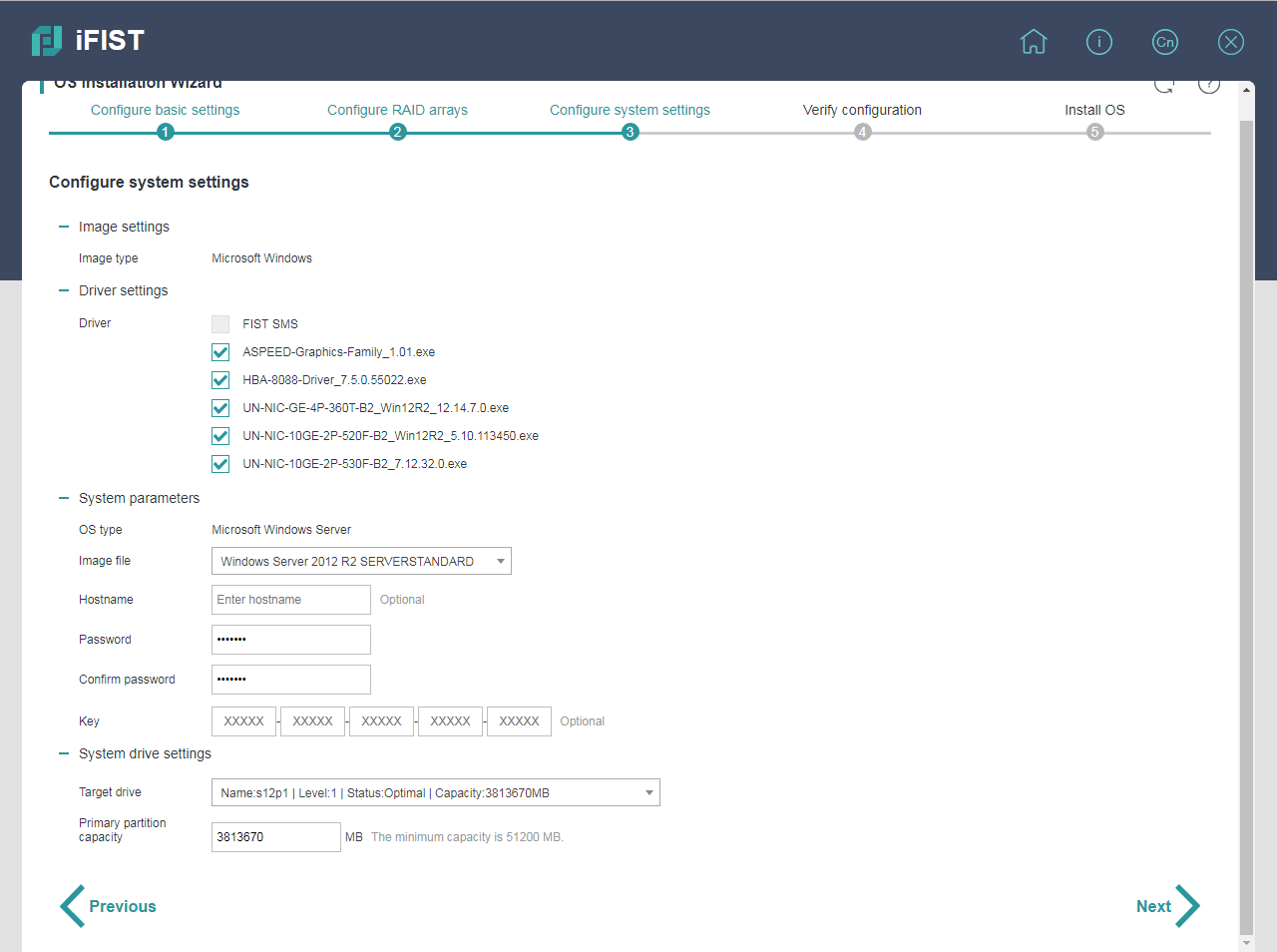
7. In the Target drive field, select the logical drive where you want to install the operating system, and then click Next.
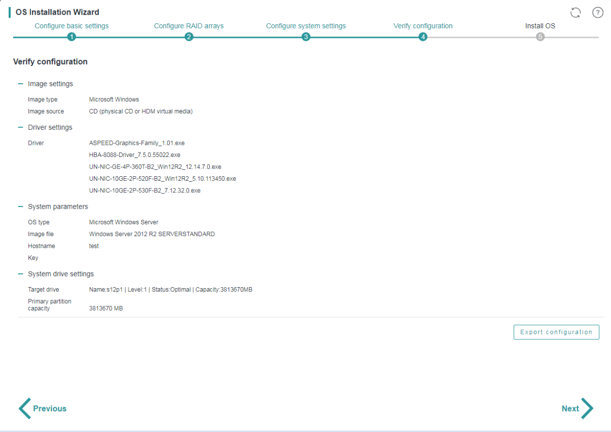
8. On the Verify configuration page, verify that the OS installation settings are correct.
Figure 197 Verifying the configuration
9. To revise the settings, click Previous. If no revision is required, click Next.
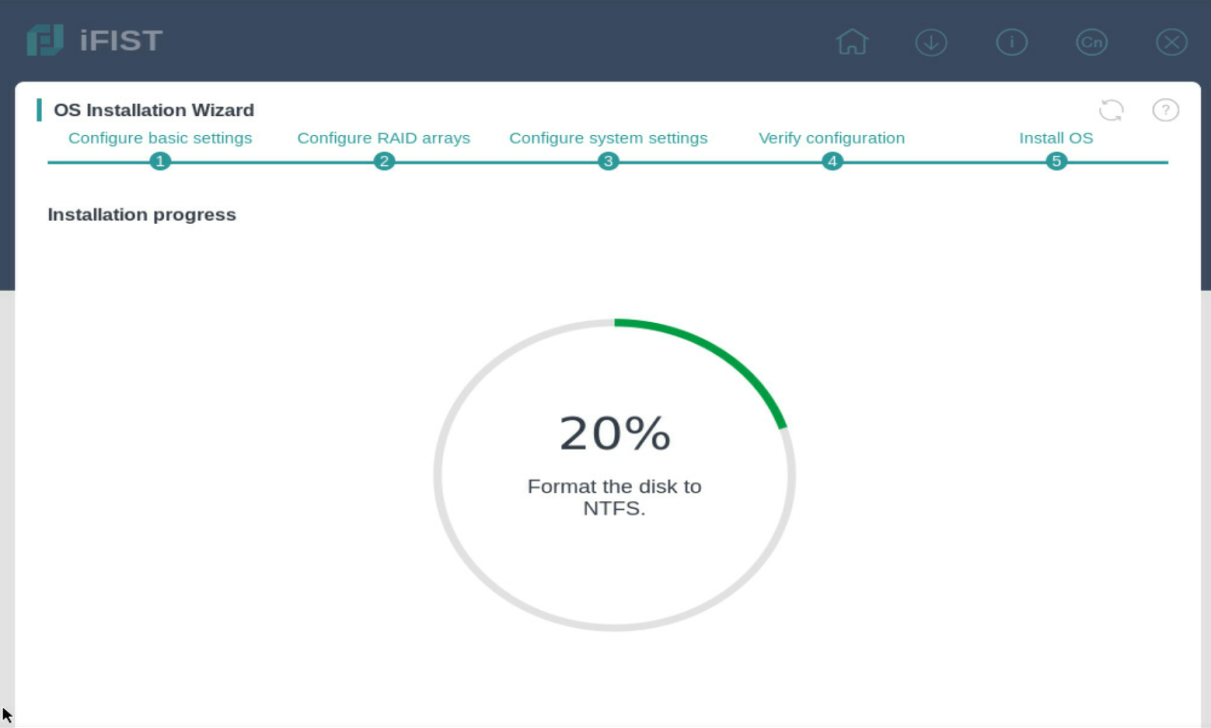
10. After you click Next on the Verify configuration page, iFIST starts to prepare the server for the OS installation and displays the real-time progress, as shown in Figure 197.
After the preparation is complete, iFIST reboots the server and installs the OS.
Figure 198 Preparing the server for OS installation
The server is automatically restarted after the OS installation is complete without manual intervention.
Installing drivers on H3C servers
You can use the following methods to install drivers on servers:
· Use FIST to install drivers on a single server or multiple servers in bulk. For more information, see H3C Servers FIST User Guide.
· Use REPO, which supports offline driver and firmware update. For more information, see H3C Servers REPO User Guide.
· Use the common methods.
This section introduces the common methods for driver installation.
Installing a Windows driver
This section updates the driver of the UNIC-CNA-10GE-2P-560F-B2 network adapter on a Windows Server 2012 R2 OS. The device name might change after the driver is updated.
Checking network adapter version
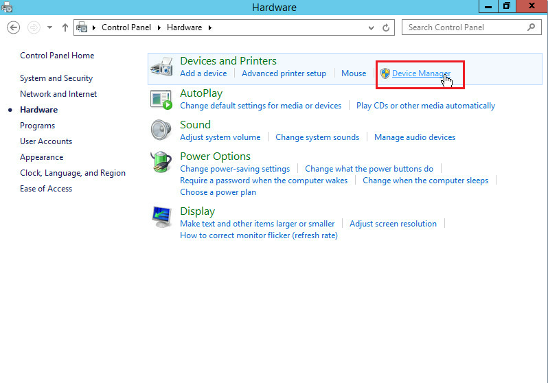
1. Click the Windows button.
2. Select Control Panel > Hardware > Device Manager.
Figure 199 Accessing Device Manager
3. Right-click on Intel(R) 82599 10 Gigabit Dual Port Network Connection, and then select Properties > Driver from the short-cut menu.
Figure 200 Device Manager
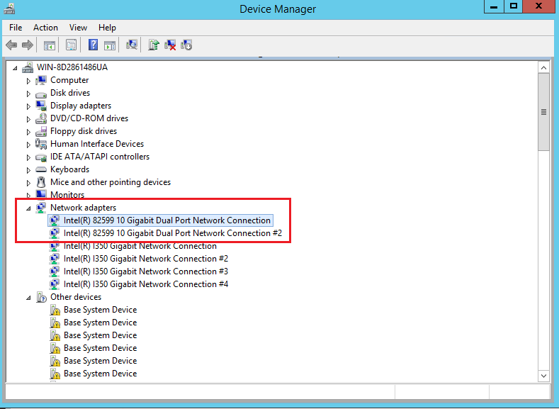
Figure 201 Displaying driver version

Installing the network adapter
1. Download the driver from the H3C website.
2. Double-click the driver, and then click Install.
If the file is an .inf file, select Update driver, select Local search in the dialog box that opens, and then select the .inf file.
Figure 202 Running the driver
3. Click OK.
Figure 203 Driver installation completed
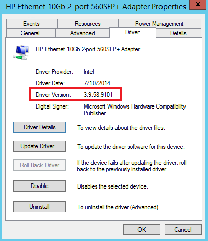
4. Display the driver version to verify that the version has been updated.
Figure 204 Displaying driver version
Installing a Linux driver
Installing a storage controller driver by using a .deb file (for Ubuntu OSs)
This section updates the driver of the RAID-P5408-Mf-8i-4GB storage controller for Ubuntu 18.04.
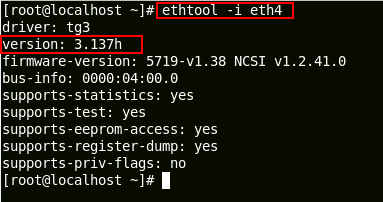
Checking the storage controller version
You can use the modinfo module_name command to display kernel module information. The kernel module name for different server components might differ. For more information about the kernel module names, see the release notes for the driver.
In this section, the kernel module name of the RAID-P5408-Mf-8i-4GB storage controller is megaraid_sas. To view the storage controller details, execute the modinfo megaraid_sas command.
As shown in Figure 204, the version field displays the driver version of the storage controller.
Figure 205 Displaying storage controller details
Installing the storage controller driver
1. Obtain the driver from the H3C website and mount the driver to the server.
2. Execute the mount command to mount the virtual media to the /mnt directory.
The virtual media often resides in the /dev/sr0 directory.
3. Execute the cd command to enter the directory where the driver resides.
4. Execute the ls command to verify that the .deb driver file has been mounted.
5. Execute the dpkg –i filename.deb command.
Figure 206 Installing the storage controller driver for a Ubuntu device
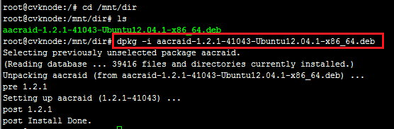
6. Execute the modinfo megaraid_sas command to verify that the driver has been installed successfully.
Installing a storage controller driver by using an .rpm file (for RedHat OSs)
This section updates the driver of the RAID-P5408-Mf-8i-4GB storage controller for RedHat 7.3.
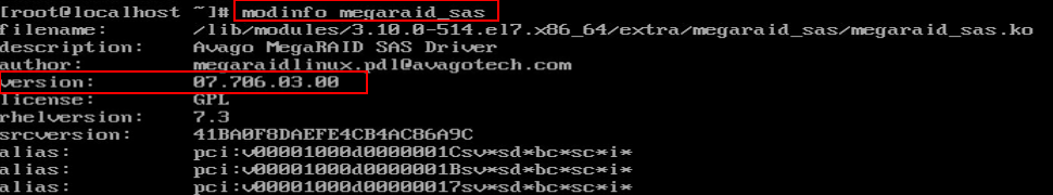
Checking the storage controller version
You can use the modinfo module_name command to display kernel module information. The kernel module name for different server components might differ. For more information about the kernel module names, see the release notes for the driver.
In this section, the kernel module name of the RAID-P5408-Mf-8i-4GB storage controller is megaraid_sas. To view the storage controller details, execute the modinfo megaraid_sas command.
As shown in Figure 206, the version field displays the driver version of the storage controller.
Figure 207 Displaying storage controller details
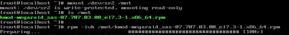
Installing the storage controller
1. Obtain the driver from the H3C website and mount the driver to the server.
2. Execute the mount command to mount the virtual media to the /mnt directory.
The virtual media often resides in the /dev/sr0 directory.
3. Execute the cd command to enter the directory where the driver resides.
4. Execute the ls command to verify that the .rpm driver file has been mounted.
5. Execute the rpm –ivh filename.rpm command.
Figure 208 Installing the storage controller driver for a RedHat device
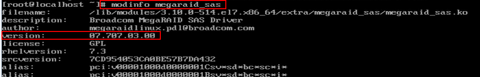
6. Execute the modinfo megaraid_sas command to verify that the driver has been installed successfully.
Figure 209 Verifying the driver installation
Installing an FC HBA driver by using a .tar.gz file (for RedHat OSs)
This section updates the driver of the FC-HBA-QLE2692-16Gb-2P-1-X FC HBA for RedHat 7.3.
Checking FC HBA version
You can use the modinfo module_name command to display kernel module information. The kernel module name for different server components might differ. For more information about the kernel module names, see the release notes for the driver.
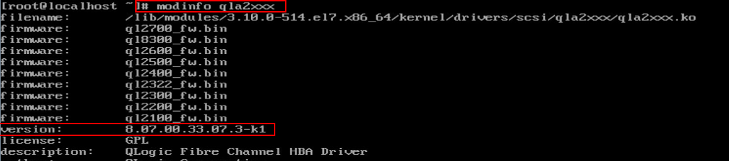
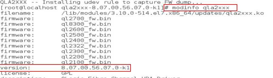
In this section, the kernel module name of the FC-HBA-QLE2692-16Gb-2P-1-X FC HBA is qla2xxx. To view the storage controller details, execute the modinfo qla2xxx command.
As shown in Figure 209, the version field displays the driver version of the storage controller.
Figure 210 Displaying FC HBA details
Installing the FC HBA
1. Obtain the driver from the H3C website and mount the driver to the server.
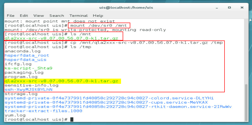
2. Execute the mount command to mount the virtual media to the /mnt directory.
The virtual media often resides in the /dev/sr0 directory.
3. Execute the ls command to verify that the .tar.gz driver file has been mounted.
4. Execute the cp command to copy the driver file in the /mnt directory to the /tmp directory.
Figure 211 Mounting and copying the driver file
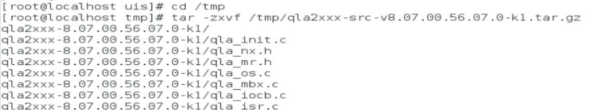
5. Execute the cd command to enter the /tmp directory where the driver resides, and then execute the tar –zxvf filename.tar.gz command to decompress the .tar.gz file.
Figure 212 Decompressing the .tar.gz file
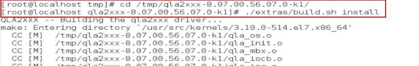
6. Execute the cd command to enter the directory where the decompressed file resides, and then execute the ./extras/build.sh install command to start driver installation.
The path for the build.sh script in this example might differ from your product.
Figure 213 Installing the driver of a FC HBA card for a RedHat device
7. Execute the modinfo qla2xxx command to verify that the driver has been installed successfully.
Figure 214 Verifying the driver installation
Installing a GPU driver by using a .run file (for RedHat OSs)
This section updates the driver of the M4000 GPU for RedHat 7.3.
Checking GPU information
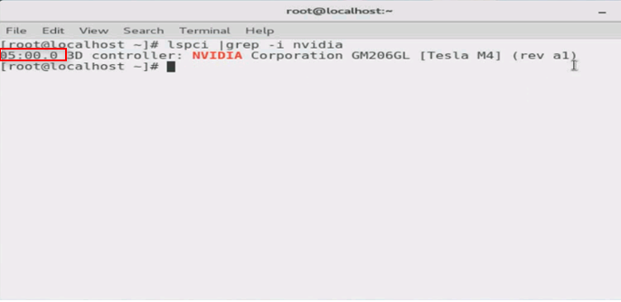
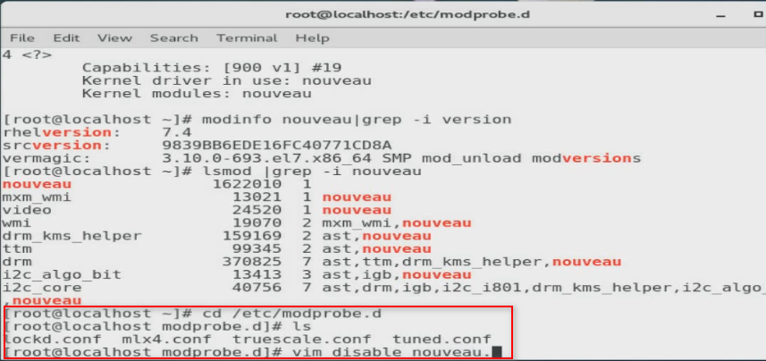
1. Execute the lspci |grep –i nvidia command to view the bus number of the GPU. In this example, the bus number is 05:00.0.
Figure 215 Displaying the bus number of the GPU
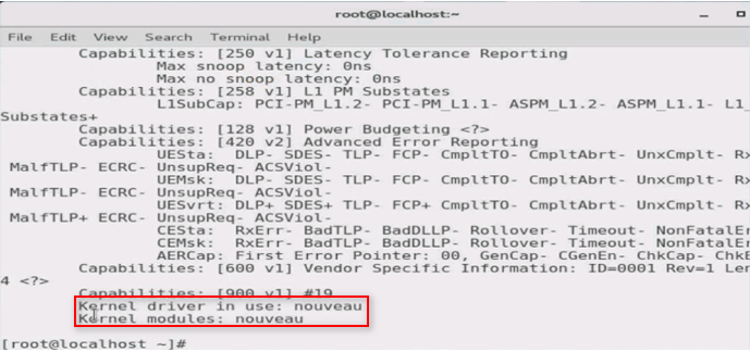
2. Execute the lspci –vvs bus command to view driver information. The bus argument represents the bus number of the GPU.
In the command output, nouveau represents the NVIDIA GPU driver integrated into the OS by default.
Figure 216 Displaying GPU driver information
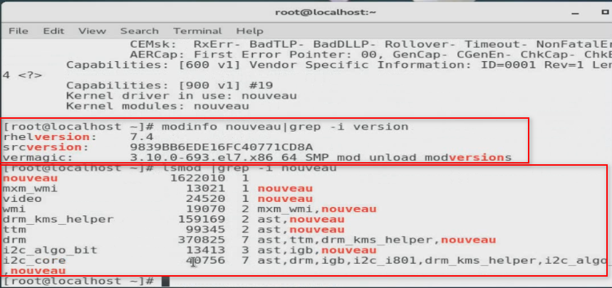
3. Execute the modinfo and lsmod commands in sequence to view GPU driver information.
Figure 217 Displaying GPU driver information
Installing the GPU driver
1. Obtain the driver from the H3C website and mount the driver to the server.
2. Disable the nouveau driver:
a. Execute the vim disable_nouveau. command to create the disable_nouveau.conf file.
Figure 218 Creating the disable_nouveau.conf file
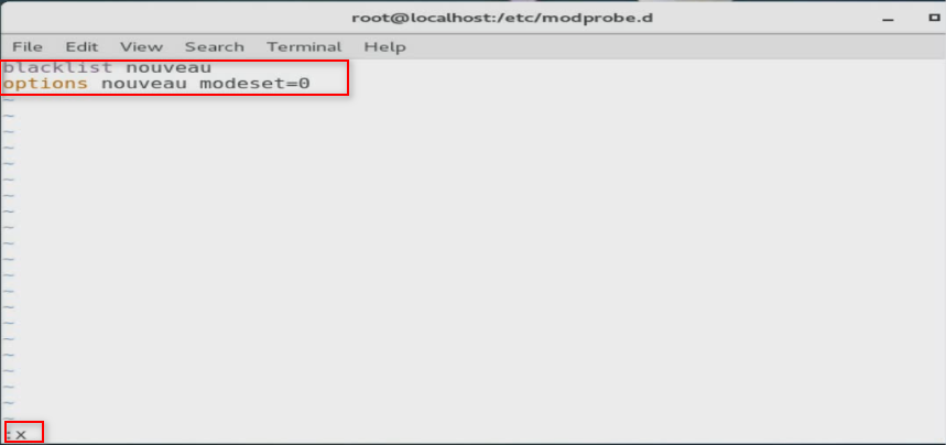
b. Add the following command lines to the file, and then exit the vim editor.
blacklist nouveau
options nouveau modeset=0
Figure 219 Adding the command lines
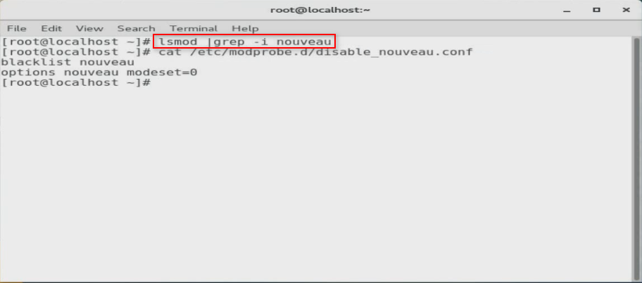
3. Reboot the server for the configuration to take effect.
4. Execute the lsmod | grep –i nouveau command to view information about the GPU driver integrated into the OS. If no GPU driver information is displayed, the system has disabled the nouveau GPU driver successfully.
Figure 220 Viewing information about the OS-integrated GPU driver
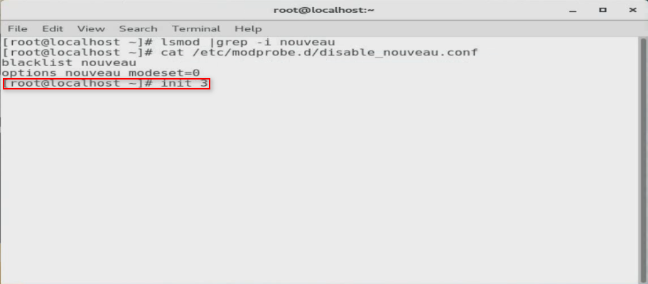
5. Execute the init 3 to switch to the CLI.
Figure 221 Switching to the CLI
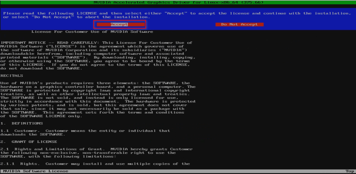
6. Execute the ./ NVIDIA-Linux-x86_64-367.44.run --no-opengl-files command to install the driver.
Figure 222 Installing a GPU driver for a RedHat device

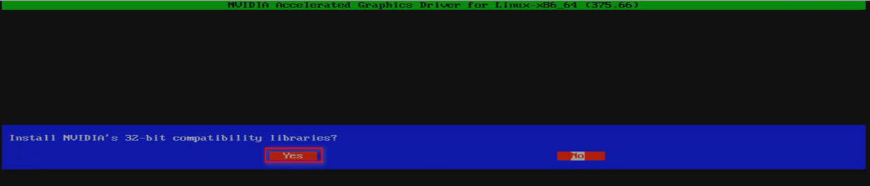
7. As shown in Figure 222 and Figure 223, select Accept and Yes, respectively.
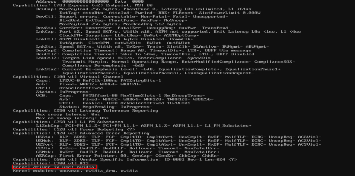
8. After the installation, execute the lspci –vvs 05:00.0 command to view information about the current GPU driver.
If the Kernel driver in use field displays nvidia, the driver has been installed successfully.
Figure 225 Viewing the current GPU driver information

Figure 226 Viewing kernel driver in use
Installing an FC HBA driver (for VMware OSs)
This section updates the driver of the FC-HBA-QLE2692-16Gb-2P-1-X FC HBA for VMware 6.7.
Prerequisites
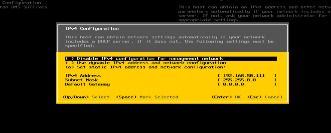
1. Install the tool for remote access on the local client.
2. Configure the IP settings for the VMware OS. Make sure the OS can reach the local client.
Figure 227 Configuring the IP settings
3. Obtain the driver from the H3C website, and then upload the VMware OS.
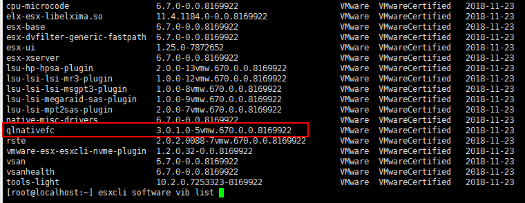
Checking the FC HBA version
Log in to VMware, and execute the esxcli software vib list command
Figure 228 Displaying FC HBA version
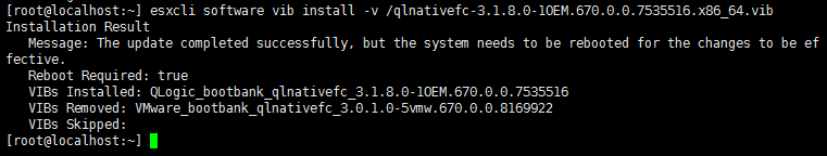
Installing the FC HBA driver
1. Execute the esxcli software vib install –v filename.vib command.
Figure 229 Installing the FC HBA driver
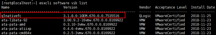
2. Execute the esxcli software vib list command to verify that the driver has been installed successfully.
Figure 230 Verifying the driver installation
Updating firmware
Updating storage controller firmware
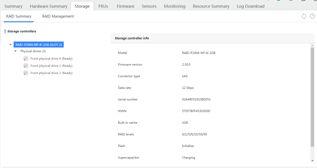
Checking the firmware version
1. Log in to the HDM Web interface.
2. In the navigation pane, select Dashboard >Storage.
3. Click the RAID Summary tab to view storage controller information.
Figure 231 Viewing firmware version
Updating the firmware
1. Obtain the firmware image from the H3C website and mount the firmware image to the server.
2. Log in to the server, and enter the BIOS setup utility.
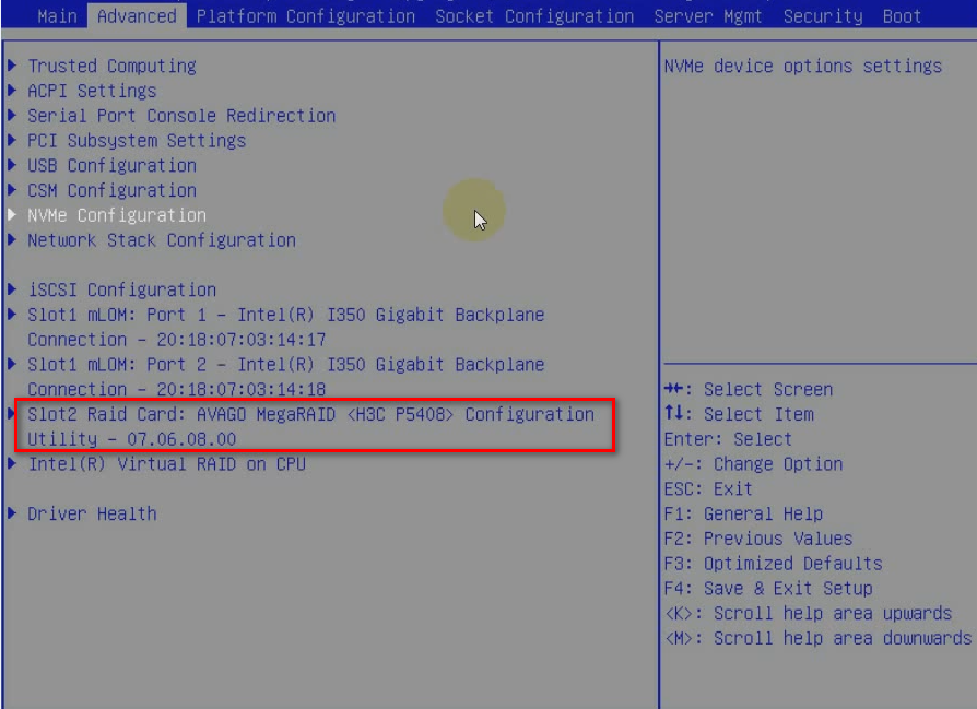
3. Click the Advanced tab, select the target storage controller, and then press Enter.
Figure 232 Entering storage controller management submenu
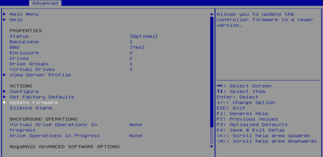
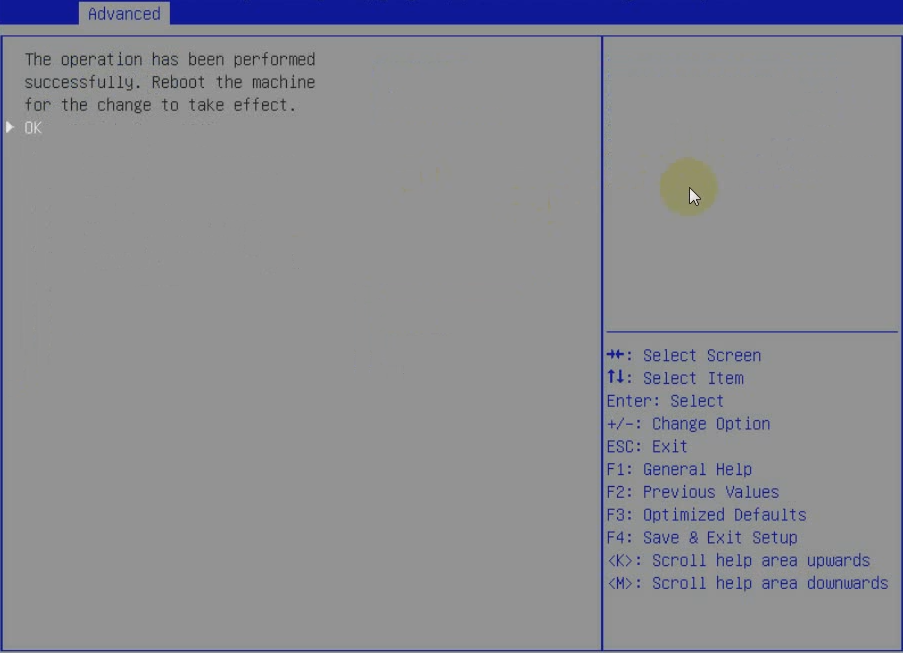
4. Select Update Firmware and press Enter.
Figure 233 Selecting Update Firmware
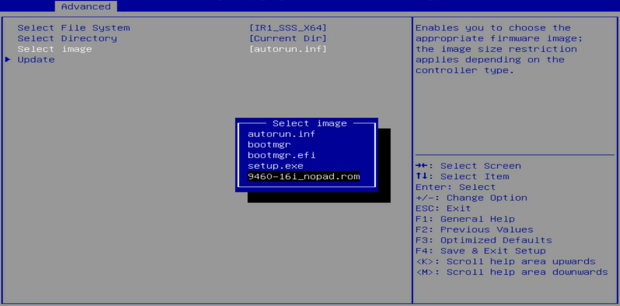
5. As shown in Figure 233, select the file system, directory, and image, select Update, and then press Enter.
Figure 234 Selecting the firmware image
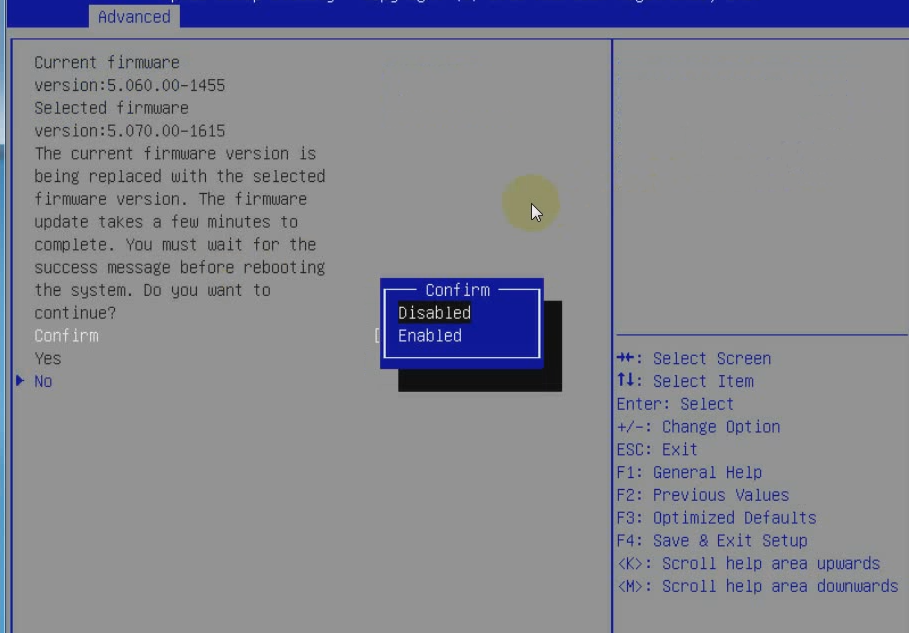
6. Verify that the current firmware version and target firmware version are correct, and select Confirm > Enabled > Yes. Then, press Enter.
Figure 235 Verifying firmware versions
7. For the new firmware to take effect, press Enter to reboot the server.
To verify that the firmware has been updated successfully, see "Checking the firmware version."
Figure 236 Rebooting the server
Troubleshooting
The /dev/root directory not found during Linux OS installation
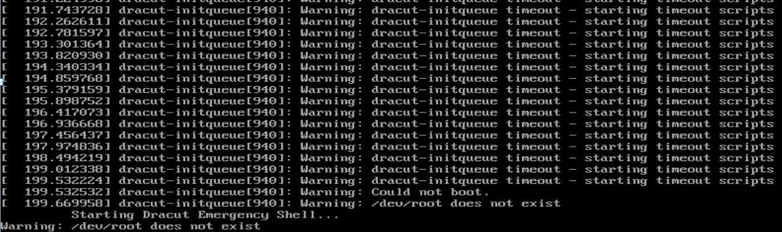
Symptom
If you use a USB disk or external connected driver to install a Linux OS, the system generates a dracut-initqueue timeout error and prompts a /dev/root does not exist message.
Figure 237 Error message
Solution
This issue is caused by the inconsistency between the partition label in GRUB and the actual USB disk or drive name.
To resolve the issue:
1. Execute the ls /dev command in GRUB to identify the partition label of the bootable USB disk or drive, for example, sda4.
2. Reboot the server.
3. As shown in Figure 237, change the drive letter path to /dev/sda4.
Figure 238 Changing the drive letter path
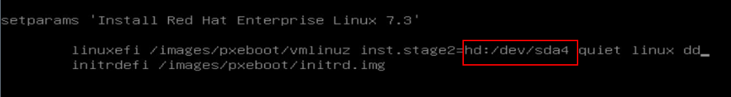
4. Press Ctrl + X to continue the installation.
SUSE11SP4 installation failure
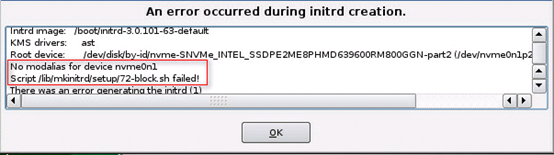
Symptom
An error occurred during initrd creation if Intel NVMe SSD is used.
Figure 239 Failure to install SUSE11SP4
Solution
To resolve the issue:
1. Mount the image through a USB disk or create an ISO file and then mount the image through KVM by following these steps:
a. Install SUSE11SP4 until the following page appears.
Figure 240 Installing SUSE11SP4
b. Press Ctrl+Alt+F2, and then execute the following commands:
#chroot /mnt
#mount /dev/cdrom /mnt
#cd /mnt
#rpm -Uvh mkinitrd-2.4.2-105.1.x86_64.rpm
2. Press Ctrl+Alt+F7 to continue installation.
3. If the issue persists, contact H3C Support.
No boot options can be found
Symptom
No boot options can be found when the following conditions are met:
· The BIOS boot mode is Legacy.
· The OS is installed on a drive connected to a storage controller, RAID-P430-M1 or HBA-1000-M2, rather than on a virtual disk.
· The storage controller operates in one of the following modes:
¡ Expose RAW or HBA mode for a RAID-P430-M1.
¡ HBA or Mixed mode for an HBA-1000-M2.
Solution
To resolve the issue:
1. Configure the drive where the OS is installed as the primary bootup option. For more information, see H3C Storage Controller User Guide.
2. If the issue persists, contact H3C Support.
Failure to enter SUSE OS in Legacy mode
Symptom
In Legacy mode, the SUSE OS installed on a second logical disk can be accessed only when the GRUB configuration file is modified manually.
Solution
To resolve the issue:
1. Install the OS on the first logical disk.
2. If the issue persists, contact H3C Support.
An error occurred during SLES12 OS installation
Symptom
If the total memory size is larger than 40G, the system prompts installation error caused by insufficient kdump space after automatic partition is selected.
Solution
SUSE assigns only 40G space to the root partition, but the dumped images will be saved in the / partition.
To resolve the issue:
1. Click kdump, and then disable kdump.
2. Click Back, and then change the partition size to ensure that it is larger than the total memory size.
3. If the issue persists, contact H3C Support.
Failure to install an OS by using PXE
Symptom
The OS fails to be installed using PXE.
Solution
The server uses a new-generation chip for mLOM adapters, and the drivers provided with a lot of OSs cannot identify these types of mLOM adapters.
To resolve the issue:
1. Install a GE-4P-360T-B2-1 network adapter. Most systems integrate network adapter drivers of this type.
2. Burn the driver of the mLOM adapter into the image of the system, and then use this image for PXE installation.
3. If the issue persists, contact H3C Support.
Failure to install a VMware OS when only mLOM adapters are installed
Symptom
A VMware OS failed to be installed when only mLOM adapters are installed.
Solution
The server detects whether a network adapter exists before installing a VMware OS. If no network adapter is detected, the OS will not be installed. The server uses a new-generation chip for mLOM adapters, and the mLOM adapter driver is not integrated into VMware, so the server cannot identify the mLOM adapter.
To resolve the issue:
1. Apply either of the following methods:
¡ Use the OS image integrated with the mLOM adapter driver to install the OS.
¡ Install a PCIe card that the VMware-provided drive can identify, for example, network adapter-GE-4P-360T-B2-1, CNA-10GE-2P-560F-B2-1, or network adapter-10GE-2P-520F-B2-1.
2. If the issue persists, contact H3C Support.
HBA-H460-M1 storage controller drive can be installed successfully only after two installation operations
Symptom
The HBA-H460-M1 storage controller drive can be installed successfully only after two installation operations.
Solution
This issue is caused by smartpqi driver and aacraid driver (provided with the card) conflict. Updating smartpqi does not update aacraid.
· To resolve the issue for a Red Hat OS:
a. Update firmware to version 0.0.B826 or higher.
b. Install smartpqi (v1.02), and then reboot the server.
c. Install aacraid (v52011) to replace aacraid provided with the storage controller.
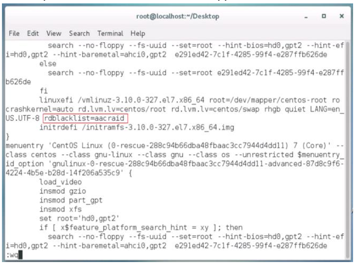
d. Add rdblacklist=aacraid to /etc/grub2-efi.cfg, and then reboot the server.
e. Execute the lspci -vvs b3:00.0 command to verify that the drive in use is smartpqi.
Figure 241 Verifying the drive in use
f. If the issue persists, contact H3C Support.
· To resolve the issue for an SUSE OS, update the smartpqi and aacraid drivers and then reboot the server.
SUSE12SP2 OS installation takes a long time and the webpage is stuck after installation
Symptom
SUSE12SP2 OS installation takes a long time and the webpage is stuck after installation if you use HBA-1000-M2-1 to set up RAID.
Solution
To resolve the issue:
1. Upgrade HBA-1000-M2-1 to FW 3.02 or higher.
2. Add kernel boot parameter linux dd when starting to install the OS.
3. Update the aacraid driver for SUSE12SP2 before you install the OS.
4. If the issue persists, contact H3C Support.
Storage controller HBA-H460-M1 FW1.04 can be installed successfully on an RHEL OS but the system prompts installation failure
Symptom
The HBA-H460-M1 storage controller with version FW1.04 can be installed successfully on an RHEL OS but the system prompts installation failure.
Solution
To resolve the issue:
1. Install the aacraid drive on the RHEL OS.
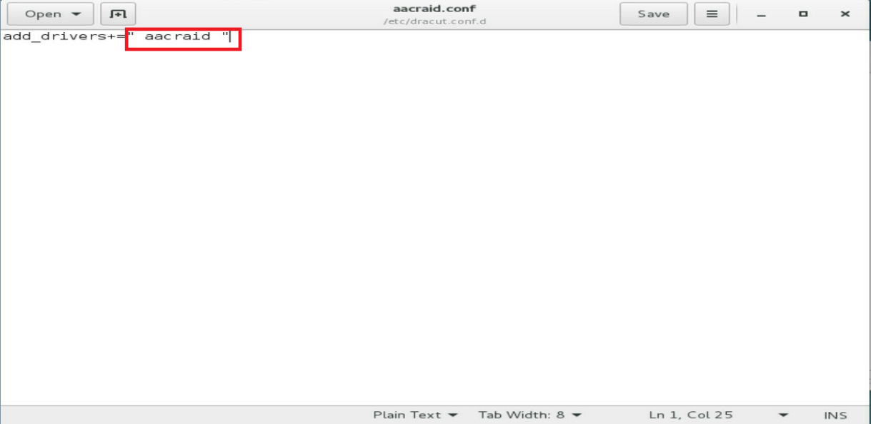
2. Add a space before and after the aacraid field in /etc/dracut.conf.d/aacraid.conf, and then save the configuration.
Figure 242 Adding spaces
3. Install the smartpqi driver.
4. Reboot the server and verify that the smartpqi driver has been installed successfully.
5. If the issue persists, contact H3C Support.
Bluescreen or kernel error occurred when BIOS NUMA is enabled and IMC0 and IMC1 for CPU 1 or CPU 2 are disabled
Symptom
A blue screen or a kernel error occurred after a server reboot when the following conditions are met:
· The operating system is installed on the logic disk of the storage controller.
· BIOS NUMA is enabled and IMC0 and IMC1 for CPU 1 or CPU 2 are disabled.
Solution
To resolve the issue:
1. Do not disable all internal model controls (IMCs) for CPU 1 or CPU 2 if NUMA is enabled, or disable NUMA if you want to disable all IMCs for CPU 1 or CPU 2.
2. If the issue persists, contact H3C Support.
An error occurred on an NVMe drive and the drive went offline after a managed hot plug
Symptom
If an OS earlier than Linux Kernel 4.3 is used, an error occurred on an NVMe drive and the drive went offline after a managed hot plug.
Solution
This issue is caused by payload inconsistency between the NVMe drive and PCIe bridge device after a managed hot plug of the NVMe drive.
To resolve the issue:
1. Use Linux Kernel 4.3 because a code for negotiating the payload has been added to this version.
2. To continue using an OS earlier than Linux Kernel 4.3, use the following methods:
Method 1:
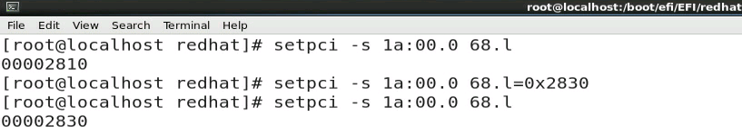
a. Use the setpci command to set the value of max_payload_size in the NVMe register to be the same as that of the bridge device.
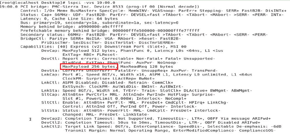
b. Display the value of payload on the PCIe bridge device. You must set the value of maxpayload in DevCtl of the NVMe drive to be the same as the value of this payload.
Figure 243 Displaying the value of the payload on the PCIe device
c. Display the value of the DevCtl field in the register, and then set the value of the maxpayload field. As shown in the following figure, if the value of the DevCtl field is 00002810, set the value of the maxpayload field to 128B. To set it to 256B, the value of the DevCtl field must be 0x2830.
Figure 244 Displaying the value of the DevCtl field in the original register
Method 2:
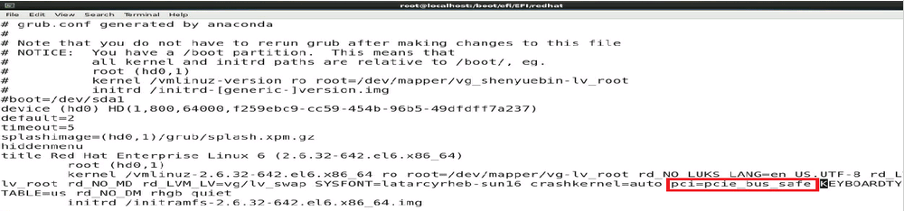
Add pci=pcie_bus_safe or pci=pcie_bus_perf to the GRUB configuration file. Use a Red Hat OS as an example. The configuration file is in the /etc/efi/EFI/redhat/grub.conf directory, as shown in Figure 244.
¡ pci=pcie_bus_safe sets the MPS of each device to the maximum MPS value supported by the devices in root_complex.
¡ pci=pcie_bus_perf sets the MPS of a device to the maximum MPS allowed by its upper level bus.
This method fixes the payload of a PCIe device at system start and ignores the payload initialized by the BIOS. This might influence bandwidth usage.
Figure 245 Adding a parameter to the GRUB configuration file
3. If the issue persists, contact H3C Support.
A blue screen occurred when the network adapter-10GE-2P-520F-B2-1 driver was being installed
Symptom
A blue screen occurred when a network adapter-10GE-2P-520F-B2-1 driver is installed in slot 2 or slot 5 on Riser 2 on a 24SFFor 8SFF R6900 server.
Solution
To resolve the issue:
1. In the C:\Windows\system32\drivers directory, delete the mlx4eth63.sys driver provided with the server, and then reboot the server.
2. Install the driver provided by the network adapter vendor.
3. If the issue persists, contact H3C Support.
Some NVMe drives might fail to be identified when multiple NVMe drives are installed after OS installation
Symptom
Some NVMe drives might fail to be identified when multiple NVMe drives are installed after OS installation.
Solution
To resolve the issue:
1. Install a next NVMe drive a minimum of 20 seconds after one NVMe drive is installed.
2. If the issue persists, contact H3C Support.
Failed to install CASE0306 on an NVMe SSD drive
Do not install CAS E0306 on an NVMe SSD drive.
The system cannot be restored after the server is powered down unexpectedly
Symptom
The system cannot be restored after the server is powered down unexpectedly and the file system is damaged.
Solution
|
|
CAUTION: Forcibly powering down the server might damage your applications or data. Be cautious to perform this operation based on your operating system. |
To resolve the issue:
1. Restart the system, select rescue mode on the GRUB page, execute the xfs_repair –L /dev/sdx command to repair the damaged partition, and then restart the system.
2. If the file system cannot be repaired, re-install the system.
3. If the issue persists, contact H3C Support.
Bluescreen occurred if chipset drivers are installed before GPU-M60-1 and GPU-M60-1-X display card drivers are installed on the Windows system
Symptom
Bluescreen occurred if chipset drivers are installed before GPU-M60-1 and GPU-M60-1-X display card drivers are installed on the Windows system.
Solution
To resolve the issue:
1. Install the display card drivers first, and then install chipset drivers.
2. If the issue persists, contact H3C Support.
Bluescreen occurred during the installation of the IB-MCX354A-FCBT-56/40Gb-2P network adapter driver on Windows Server 2012 R2
Symptom
Bluescreen occurred during the installation of the IB-MCX354A-FCBT-56/40Gb-2P network adapter driver on Windows Server 2012 R2 on a R6900, as shown in the following figure.
Figure 246 Bluescreen during network adapter driver installation

Solution
To resolve the issue:
· Method 1:
a. Remove the IB-MCX354A-FCBT-56/40Gb-2P network adapter driver provided with Windows Server 2012 R2, and then install the network adapter driver provided by Mellanox.
Figure 247 Installing Mellanox network adapter driver
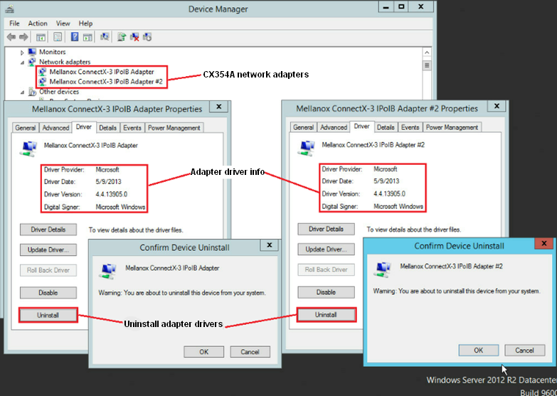
b. If the issue persists, contact H3C Support.
· Method 2:
c. Access BIOS Setup > Advanced > Socket Configuration > Processor Configuration, set Hyper-Threading[All] to Disabled, install the network adapter driver provided by Mellanox, and then enable hyper threading.
Figure 248 Setting hyper threading
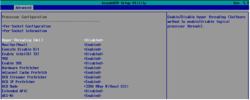
b. If the issue persists, contact H3C Support.
OS installation takes a long time when the OS image is mounted through an HDM shared network interface
Symptom
OS installation takes a long time when the link speed is 1000 Mbps between an HDM network interface and the peer interface.
Solution
To resolve the issue:
1. Change the transmission rate of the peer interface to 100 Mbps because the shared network interface supports autonegotiation.
2. If the issue persists, contact H3C Support.
CAS E0306 OS installation failure
CAS E0306 OS installation is not supported because this version does not contain the Smartpqi driver required by PMC SmartIOC 2100/SmartROC 3154.
Blue screen or other errors occurred when the chipset driver is updated on an R5300 server installed with the Windows Server 2016 OS
Install the most recent patch file for the Windows system.
Black screen of death occurred during RedHat 8.3 or CentOS 8.3 installation on a server installed with a NVIDIA GPU
Symptom
Black screen of death occurred during RedHat 8.3 or CentOS 8.3 installation no matter which BIOS boot mode and server boot order are used when the server is installed with a NVIDIA GPU.
Solution
This issue is caused because the GPU driver nouveau that comes with RedHat 8.3 or CentOS 8.3 is incompatible with NVIDIA GPUs.
The section uses the CentOS 8.3 as an example.
To resolve the issue:
1. Enter the OS installation confirmation screen, select Install CentOS Linux 8, and press e.
Figure 249 Confirming OS installation
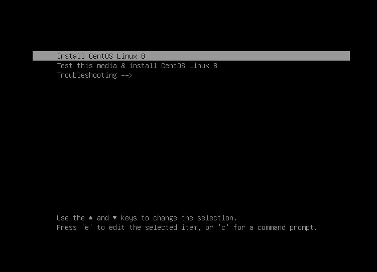
Figure 250 Parameter configuration screen
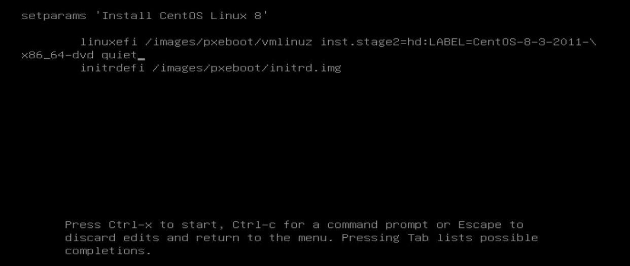
2. On the parameter configuration screen, delete quiet and enter modprobe.blacklist=nouveau to delete GPU driver nouveau.
Figure 251 Deleting the GPU driver
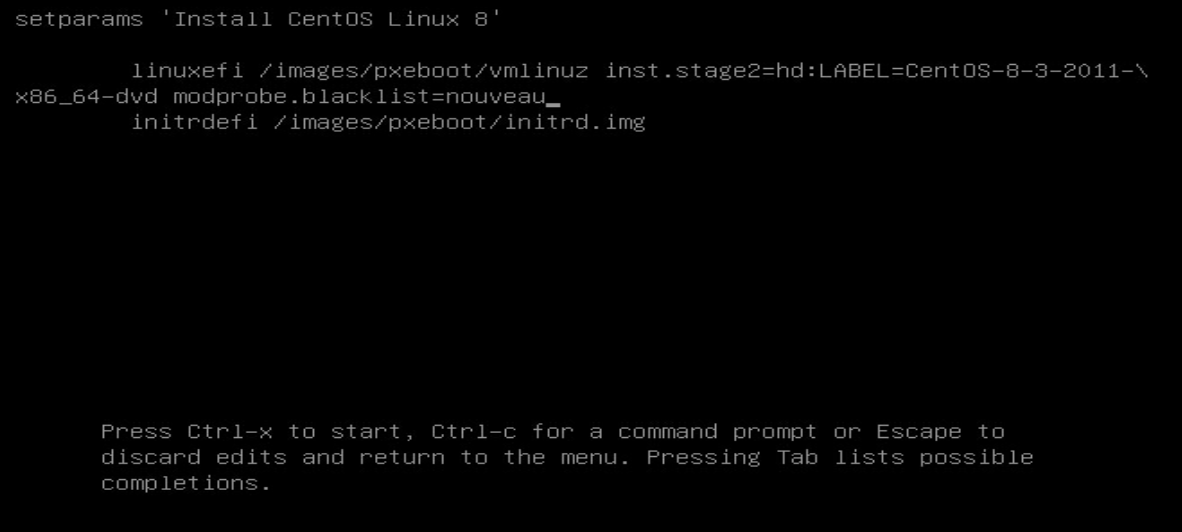
3. Press Ctrl+x to start OS installation.
Acronyms
Table 5 Acronyms
|
Acronym |
Full name |
|
H |
|
|
HDM |
Hardware Device Management |
|
I |
|
|
iFIST |
Integrated Fast Intelligent Scalable Toolkit |
|
K |
|
|
KVM |
Keyboard Video Mouse |
|
PXE |
Preboot Execute Environment |
|
R |
|
|
RAID |
Redundant Arrays of Independent Disks |
|
S |
|
|
SAN |
Storage Area Network |
|
U |
|
|
UEFI |
Unified Extensible Firmware Interface |
