- Table of Contents
- Related Documents
-
| Title | Size | Download |
|---|---|---|
| 02-Appendix A Chassis views and technical specifications | 1.62 MB |
Contents
1 Appendix A Chassis views and technical specifications
F1000-AI-20/F1000-AI-30/F1000-AI-50
Network data encryption modules
High-voltage DC power supplies
Network data encryption modules
1 Appendix A Chassis views and technical specifications
Chassis views
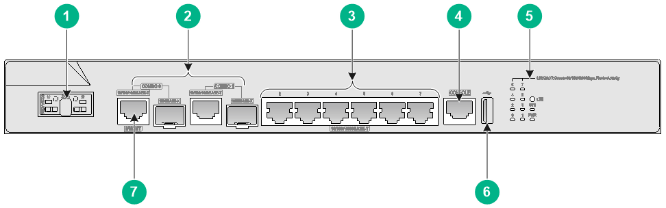
F1000-AI-03
The F1000-AI-03 firewall provides the following ports on the front panel:
· Eight 10/100/1000BASE-T autosensing Ethernet copper ports.
· Two combo interfaces.
· One console port.
· One USB port.
· One drive slots.
Figure1-1 Front panel
|
(1) Drive slot |
(2) Combo interfaces |
|
(3) 10/100/1000BASE-T Ethernet copper ports |
(4) Console port |
|
(5) LEDs |
(6) USB port |
|
(7) Management Ethernet port (0/MGMT) |
|
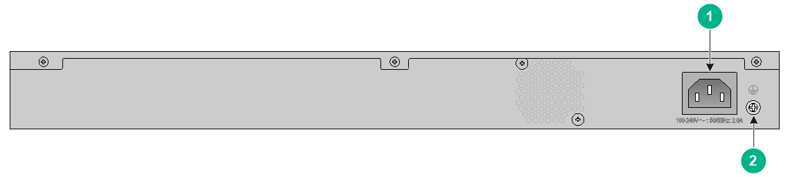
Figure1-2 Rear panel

|
(1) Grounding screw |
(2) Power receptacle |
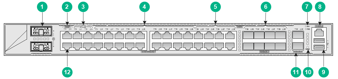
F1000-AI-10
The F1000-AI-10 firewall provides the following ports on the front panel:
· Eighteen 10/100/1000BASE-T autosensing Ethernet copper ports.
· Two 10GBASE-R Ethernet fiber ports.
· Two management Ethernet ports.
· Four bypass ports.
· Eight combo interfaces.
· One console port.
· Two USB ports.
· One reset button.
· Two drive slots.
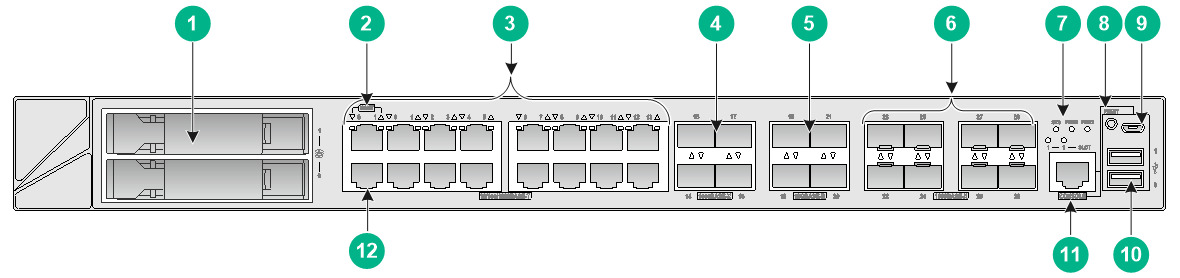
Figure1-3 Front panel
|
(1) Drive slots |
(2) Management Ethernet port (1/MGMT) |
|
|
(3) Bypass ports |
(4) 10/100/1000BASE-T Ethernet copper ports |
|
|
(5) 10/100/1000BASE-T Ethernet copper ports (combo) |
(6) 1000BASE-X Ethernet fiber ports (combo) |
|
|
(7) LEDs |
(8) Console port |
|
|
(9) USB ports |
(10) Reset button (for device reboot only, and does not restore the factory default) |
|
|
(11) 10GBASE-R Ethernet fiber ports |
(12) Management Ethernet port (0/MGMT) |
|
|
(1) Power receptacle |
(2) Grounding screw |
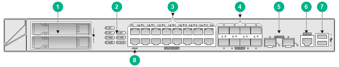
F1000-AI-20/F1000-AI-30/F1000-AI-50
The F1000-AI-20/F1000-AI-30/F1000-AI-50 firewall provides the following ports on the front panel:
· Sixteen 10/100/1000BASE-T autosensing Ethernet copper ports.
· Eight 1000BASE-X Ethernet fiber ports.
· Two 10GBASE-R Ethernet fiber ports.
· Two USB ports.
· One console port.
· Two drive slots.
· One management Ethernet port.
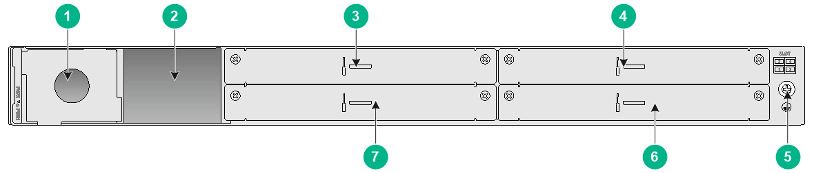
Figure1-5 Front panel
|
(1) Drive slots |
(2) LEDs |
|
(3) 10/100/1000BASE-T Ethernet copper ports |
(4) 1000BASE-X Ethernet fiber ports |
|
(5) 10GBASE-R Ethernet fiber ports |
(6) Console port |
|
(7) USB ports |
(8) Management Ethernet port (0/MGMT) |
Figure1-6 Rear panel
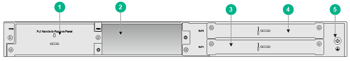
|
(1) Power supply slot 0 |
(2) Power supply slot 1 |
|
(3) Interface module slot 1 |
(4) Interface module slot 2 |
|
(5) Grounding screw |
|
F1000-AI-60
The F1000-AI-60 firewall provides the following ports on the front panel:
· Fourteen 10/100/1000BASE-T autosensing Ethernet copper ports.
· Twelve 1000BASE-X Ethernet fiber ports.
· Four 10GBASE-R Ethernet fiber ports.
· Two USB ports.
· One console port.
· One micro USB console port.
· Two drive slots.
· Two management Ethernet ports.
Figure1-7 Front panel
|
(1) Drive slots |
(2) Management Ethernet port (1/MGMT) |
|
(3) 10/100/1000BASE-T Ethernet copper ports |
(4) 1000BASE-X Ethernet fiber ports |
|
(5) 10GBASE-R Ethernet fiber ports |
(6) 1000BASE-X Ethernet fiber ports |
|
(7) LEDs |
(8) Reset button (for device reboot only, and does not restore the factory default) |
|
(9) Micro USB console port |
(10) USB ports |
|
(11) Console port |
(12) Management Ethernet port (0/MGMT) |
Figure1-8 Rear panel

|
(1) Power supply slot 1 |
(2) Power supply slot 2 |
|
(3) Interface module slot 2 |
(4) Interface module slot 4 (not supported) |
|
(5) Grounding screw |
(6) Interface module slot 3 (not supported) |
|
(7) Interface module slot 1 |
|
F1000-AI-70
The F1000-AI-70 firewall provides the following ports on the front panel:
· Fourteen 10/100/1000BASE-T autosensing Ethernet copper ports.
· Twelve 1000BASE-X Ethernet fiber ports.
· Four 10GBASE-R Ethernet fiber ports.
· Two USB ports.
· One console port.
· One micro USB console port.
· Two drive slots.
· Two management Ethernet ports.
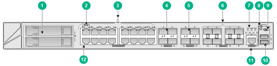
Figure1-9 Front panel
|
(1) Drive slots |
(2) Management Ethernet port (1/MGMT) |
|
(3) 10/100/1000BASE-T Ethernet copper ports |
(4) 1000BASE-X Ethernet fiber ports |
|
(5) 10GBASE-R Ethernet fiber ports |
(6) 1000BASE-X Ethernet fiber ports |
|
(7) LEDs |
(8) Reset button (for device reboot only, and does not restore the factory default) |
|
(9) Micro USB console port |
(10) USB ports |
|
(11) Console port |
(12) Management Ethernet port (0/MGMT) |
Figure1-10 Rear panel

|
(1) Power supply slot 1 |
(2) Power supply slot 2 |
|
(3) Interface module slot 2 |
(4) Interface module slot 4 |
|
(5) Grounding screw |
(6) Interface module slot 3 |
|
(7) Interface module slot 1 |
|
F1000-AI-80/F1000-AI-90
The F1000-AI-80/F1000-AI-90 firewall provides the following ports on the front panel:
· Fourteen 10/100/1000BASE-T autosensing Ethernet copper ports.
· Eight 1000BASE-X Ethernet fiber ports.
· Eight 10GBASE-R Ethernet fiber ports.
· Two USB ports.
· One console port.
· One micro USB console port.
· Two drive slots.
· Two management Ethernet ports.
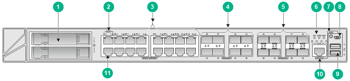
Figure1-11 Front panel
|
(1) Drive slots |
(2) Management Ethernet port (1/MGMT) |
|
(3) 10/100/1000BASE-T Ethernet copper ports |
(4) 10GBASE-R Ethernet fiber ports |
|
(5) 1000BASE-X Ethernet fiber ports |
(6) LEDs |
|
(7) Reset button (for device reboot only, and does not restore the factory default) |
(8) Micro USB console port |
|
(9) USB ports |
(10) Console port |
|
(11) Management Ethernet port (0/MGMT) |
|
Figure1-12 Rear panel
|
(1) Power supply slot 1 |
(2) Power supply slot 2 |
|
(3) Interface module slot 2 |
(4) Interface module slot 4 |
|
(5) Grounding screw |
(6) Interface module slot 3 |
|
(7) Interface module slot 1 |
|
Interface modules
|
|
CAUTION: Do not hot swap interface modules. |
Table1-1 displays the slots available for interface module installation.
Table1-1 Interface module and device slot compatibility
|
Firewall model |
Slot number |
Slot specification |
Available interface modules |
|
F1000-AI-03/F1000-AI-10 |
N/A |
N/A |
Not supported |
|
F1000-AI-20/F1000-AI-30 /F1000-AI-50 |
Slots 1 and 2 |
Low speed |
· NSQM1GT4PFC · NSQM1GP4FBA |
|
F1000-AI-60 |
Slot 1 |
High speed |
NS-NIM-TG6A |
|
Slot 2 |
Low speed |
· NSQM1GT4PFC · NSQM1GP4FBA |
|
|
F1000-AI-70/F1000-AI-80 /F1000-AI-90 |
Slots 1 and 3 |
High speed |
NS-NIM-TG6A |
|
Slots 2 and 4 |
Low speed |
· NSQM1GT4PFC · NSQM1GP4FBA |
NSQM1GT4PFC
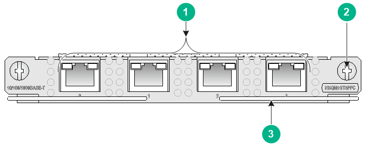
The NSQM1GT4PFC interface module provides four 10/100/1000BASE-T Ethernet copper ports.
· When the firewall is operating correctly, the four ports operate as common data ports.
· When the firewall is powered off, the four ports are divided into two bypass port pairs with ports 0 and 1 in one pair and ports 2 and 3 in another pair. The two ports in a pair can act as the uplink and downlink interfaces for a Layer 2 link and form a bypass link. This enables traffic to be transmitted through the firewall even if the firewall is powered off and ensures service continuity.
Figure1-13 Front panel of the NSQM1GT4PFC interface module
|
(1) 10/100/1000BASE-T Ethernet copper ports |
(2) Captive screw |
|
(3) Ejector lever |
|
NSQM1GP4FBA
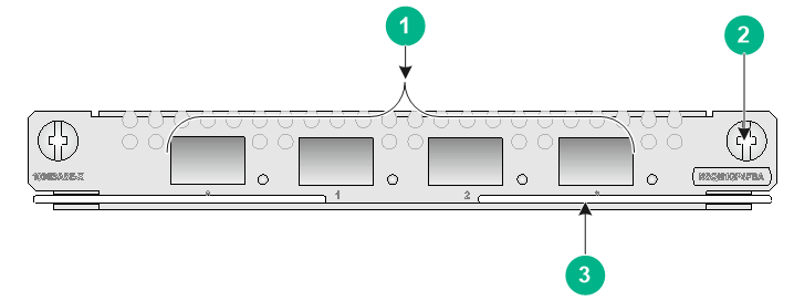
The NSQM1GP4FBA interface module provides four 1000BASE-X Ethernet fiber ports.
Figure1-14 Front panel of the NSQM1GP4FBA interface module
|
(1) 1000BASE-X Ethernet fiber ports |
(2) Captive screw |
|
(3) Ejector lever |
|
NS-NIM-TG6A
The NS-NIM-TG6A interface module provides six 10GBASE-R Ethernet fiber ports.
Figure1-15 Front panel of the NS-NIM-TG6A interface module

|
(1) 10GBASE-R Ethernet fiber ports |
(2) Captive screw |
|
(3) Ejector lever |
|
Network data encryption modules
|
|
CAUTION: Do not hot swap network data encryption modules. |
The appearance of network data encryption modules varies by models. For more information, see H3C SecPath Firewall Network Data Encryption Module Guide.
Table1-2 describes the network data encryption module compatibility with the firewalls and software.
Table1-2 Network data encryption module compatibility with the firewalls and software
|
Network data encryption module |
Applicable firewalls and slots |
Applicable software version |
|
NSQM1F1KGM0 |
· F1000-AI-20/F1000-AI-30/F1000-AI-50: Slot 1 · F1000-AI-60: Slot 1 · F1000-AI-70/F1000-AI-80/F1000-AI-90: Slots 1 and 3 |
· F1000-AI-20/F1000-AI-30/F1000-AI-50: R9333 and later · F1000-AI-60: R8601P24 and later · F1000-AI-70/F1000-AI-80/F1000-AI-90: R8601P24 and later |
|
NSQM1F1KGMB |
· F1000-AI-20/F1000-AI-30/F1000-AI-50: Slots 1 and 2 · F1000-AI-60: Slots 1 · F1000-AI-70/F1000-AI-80/F1000-AI-90: Slots 1 to 4 |
· F1000-AI-20/F1000-AI-30/F1000-AI-50: R9345 and later · F1000-AI-60: R8601P24 and later · F1000-AI-70/F1000-AI-80/F1000-AI-90: R8601P24 and later |
|
NSQM1F1KGMC |
· F1000-AI-20/F1000-AI-30/F1000-AI-50: Slots 1 and 2 · F1000-AI-60: Slots 1 · F1000-AI-70/F1000-AI-80/F1000-AI-90: Slots 1 to 4 |
· F1000-AI-20/F1000-AI-30/F1000-AI-50: R9345P14 and later · F1000-AI-60: R8601P24 and later · F1000-AI-70/F1000-AI-80/F1000-AI-90: R8601P24 and later |
Drives
|
|
CAUTION: Do not hot swap drives. |
Table1-3 describes the compatibility between drives and F1000-AI-X0 firewalls.
Table1-3 Drive compatibility with F1000-AI-X0 firewalls
|
Drive |
F1000-AI-03/F1000-AI-10 |
F1000-AI-20/F1000-AI-30/F1000-AI-50 |
F1000-AI-60/F1000-AI-70/F1000-AI-80/F1000-AI-90 |
|
NS-SSD-480G-SATA-M.2 |
Yes |
No |
No |
|
NS-SSD-480G-SATA-SFF |
No |
Yes |
Yes |
|
NS-HDD-500G-SATA-SFF |
No |
No |
Yes |
|
NS-HDD-1T-SATA-SFF |
No |
No |
Yes |
Power supplies
The F1000-AI-20, F1000-AI-30, F1000-AI-50, F1000-AI-60, F1000-AI-70, F1000-AI-80, and F1000-AI-90 firewalls each come with power supply slot PWR0 installed with a filler panel and power supply slot PWR1 empty. It supports both AC and DC power supplies. No power supplies are provided with the firewall. Prepare power supplies for the firewall yourself as required.
The F1000-AI-20, F1000-AI-30, F1000-AI-50, F1000-AI-60, F1000-AI-70, F1000-AI-80, and F1000-AI-90 firewalls each support hot swapping of power supplies and 1+1 power supply redundancy. To install two power supplies for the firewall, make sure they are the same model.
Table1-4 Power supplies available for the firewall
|
Firewall model |
Available power supplies |
|
F1000-AI-03/F1000-AI-10 |
One built-in power supply |
|
F1000-AI-20/F1000-AI-30/F1000-AI-50 (two power supplies slots PWR0 and PWR1) |
· PSR150-A1 · PSR150-D1 |
|
F1000-AI-60/F1000-AI-70/F1000-AI-80/F1000-AI-90 (two power supplies slots PWR0 and PWR1) |
· PSR250-12A1 · PSR450-12AHD · PSR450-12D |
AC power supplies
PSR150-A1
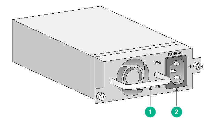
The PSR150-A1 power supply with a product code of PSR150-A1-B provides a maximum output power of 150 W.
Figure1-16 PSR150-A1 power supply
|
(1) Handle |
(2) Power receptacle |
PSR250-12A1
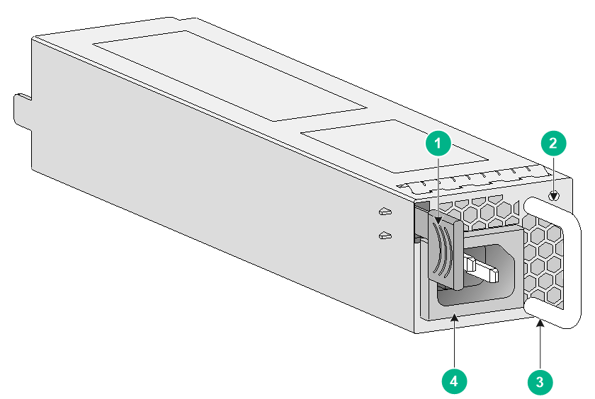
The PSR250-12A1 power supply with a product code of PSR250-12A1 provides a maximum output power of 250 W.
Figure1-17 PSR250-12A1 power supply
|
(1) Latch |
(2) Status LED |
|
(3) Handle |
(4) Power receptacle |
DC power supplies
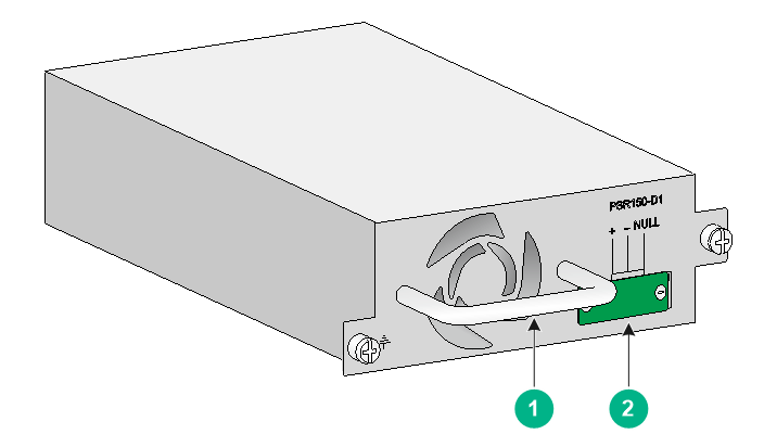
PSR150-D1
The PSR150-D1 power supply with a product code of PSR150-D1-B provides a maximum output power of 150 W.
Figure1-18 PSR150-D1 power supply
|
(1) Handle |
(2) Power receptacle |
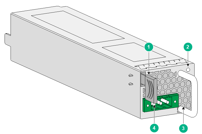
PSR450-12D
The PSR450-12D power supply with a product code of PSR450-12D provides a maximum output power of 450 W.
Figure1-19 PSR450-12D power supply
|
(1) Latch |
(2) Status LED |
|
(3) Handle |
(4) Power receptacle |
High-voltage DC power supplies
|
|
CAUTION: You can install high-voltage DC power supplies only on the F1000-AI-60, F1000-AI-70, F1000-AI-80, and F1000-AI-90 firewalls. |
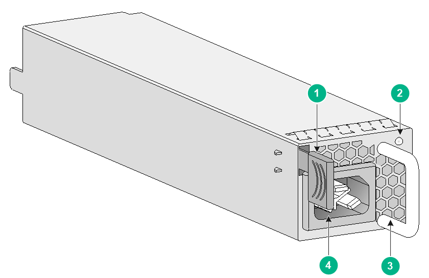
PSR450-12AHD
The PSR450-12AHD power supply with a product code of PSR450-12AHD provides a maximum output power of 450 W.
Figure1-20 PSR450-12AHD power supply
|
(1) Latch |
(2) Status LED |
|
(3) Handle |
(4) Power receptacle |
Dimensions and weights
The weight of the firewall includes the chassis and its removable components.
Chassis
Table1-5 Chassis dimensions and weights
|
Dimensions (H × W × D), excluding rubber feet and mounting brackets |
Weight (fully configured) |
|
|
F1000-AI-03 |
43.6 × 330 × 230 mm (1.72 × 12.99 × 9.06 in) |
3 kg (6.61 lb) |
|
F1000-AI-10 |
44 × 440 × 260 mm (1.73 × 17.32 × 10.24 in) |
3.7 kg (8.16 lb) |
|
F1000-AI-20/F1000-AI-30/F1000-AI-50 |
44.2 × 440 × 435 mm (1.74 × 17.32 × 17.13 in) |
8.5 kg (18.74 lb) |
|
F1000-AI-60/F1000-AI-70/F1000-AI-80/F1000-AI-90 |
44 × 440 × 435 mm (1.73 × 17.32 × 17.13 in) |
10 kg (22.05 lb) |
Interface modules
Table1-6 Interface module dimensions and weights
|
Interface module model |
Dimensions (H × W × D) |
Weight |
|
NSQM1GT4PFC |
19 × 150 × 172.9 mm (0.75 × 5.91 × 6.81 in) |
0.45 kg (0.99 lb) |
|
NSQM1GP4FBA |
19 × 150 × 172.9 mm (0.75 × 5.91 × 6.81 in) |
0.42 kg (0.93 lb) |
|
NS-NIM-TG6A |
19 × 150 × 172.9 mm (0.75 × 5.91 × 6.81 in) |
0.4 kg (0.88 lb) |
Drives
Table1-7 Drive dimensions and weights
|
Drive model |
Dimensions (H × W × D) |
Weight |
|
NS-SSD-480G-SATA-M.2 |
12.1 × 27.1 × 99.4 mm (0.48 × 1.07 × 3.91 in) |
0.05 kg (0.11 lb) |
|
NS-SSD-480G-SATA-SFF |
19 × 75.7 × 118.4 mm (0.75 × 2.98 × 4.66 in) |
0.07 kg (0.15 lb) |
|
NS-HDD-500G-SATA-SFF |
19 × 75.7 × 118.4 mm (0.75 × 2.98 × 4.66 in) |
0.12 kg (0.26 lb) |
|
NS-HDD-1T-SATA-SFF |
19 × 75.7 × 118.4 mm (0.75 × 2.98 × 4.66 in) |
0.14 kg (0.31 lb) |
Storage media
Table1-8 Storage media specifications
|
Firewall model |
Memory |
|
F1000-AI-03/F1000-AI-10 |
2GB DDR4 |
|
F1000-AI-20 |
2GB DDR3 |
|
F1000-AI-30/F1000-AI-50 |
4GB DDR3 |
|
F1000-AI-60/F1000-AI-70 |
8GB DDR4 |
|
F1000-AI-80/F1000-AI-90 |
16GB DDR4 |
Table1-9 Memory specifications of drives
|
Drive model |
Memory |
|
NS-SSD-480G-SATA-M.2 |
480 GB |
|
NS-SSD-480G-SATA-SFF |
480 GB |
|
NS-HDD-500G-SATA-SFF |
500 GB |
|
NS-HDD-1T-SATA-SFF |
1 TB |
Power consumption
The system power consumption includes the power consumptions of the chassis and the removable components.
Chassis
Table1-10 Chassis power consumption
|
Firewall model |
Power consumption |
|
F1000-AI-03 |
32 W |
|
F1000-AI-10 |
39 W |
|
F1000-AI-20/F1000-AI-30/F1000-AI-50 |
116 W |
|
F1000-AI-60/F1000-AI-70/F1000-AI-80/F1000-AI-90 |
180 W |
Interface modules
Table1-11 Interface module power consumption
|
Interface module model |
Power consumption |
|
NSQM1GT4PFC |
11.5 W |
|
NSQM1GP4FBA |
10.4 W |
|
NS-NIM-TG6A |
11 W |
Drives
Table1-12 Drive power consumption
|
Drive model |
Power consumption |
|
NS-SSD-480G-SATA-M.2 |
4.5 W |
|
NS-SSD-480G-SATA-SFF |
3 W |
|
NS-HDD-500G-SATA-SFF |
4.9 W |
|
NS-HDD-1T-SATA-SFF |
5 W |
Network data encryption modules
Table1-13 Network data encryption module power consumption
|
Network data encryption module model |
Power consumption |
|
NSQM1F1KGM0 |
4.14 W |
|
NSQM1F1KGMB |
3.7 W |
|
NSQM1F1KGMC |
5.7 W |
Power supply specifications
Table1-14 AC power supply specifications
|
Model |
Rated input voltage range |
Maximum input current |
Maximum power |
|
PSR150-A1 |
100 VAC to 240 VAC @ 50 Hz or 60 Hz |
2 A |
150 W |
|
PSR250-12A1 |
100 VAC to 240 VAC @ 50 Hz or 60 Hz |
5 A |
250 W |
Table1-15 DC power supply specifications
|
Model |
Rated input voltage range |
Maximum input current |
Maximum power |
|
PSR150-D1 |
–48 VDC to –60 VDC |
6 A |
150 W |
|
PSR450-12D |
–48 VDC to –60 VDC |
15 A |
450 W |
Table1-16 High-voltage DC power supply specifications
|
Model |
Rated input voltage range |
Maximum input current |
Maximum power |
|
|
PSR450-12AHD |
AC input |
100 VAC to 240 VAC @ 50 Hz or 60 Hz |
7 A |
450 W |
|
High-voltage DC input |
240 VAC to 380 VAC |
3.5 A |
450 W |
|
Port specifications
Console port
Table1-17 Console port specifications
|
Item |
Specification |
|
Connector |
RJ-45 |
|
Standard compliant |
RS-232 |
|
Baud rate |
9600 bps (default) to 115200 bps |
|
Cable type |
Common asynchronous serial port cable |
|
Transmission distance |
≤ 15 m (49.21 ft) |
|
Services |
· Connection to an ASCII terminal · Connection to the serial port of a local PC running the terminal emulation program · CLI |
Micro USB console port
Table1-18 Micro USB console port specifications
|
Item |
Specification |
|
Connector |
Micro USB console |
|
Standard compliant |
Micro USB |
|
Baud rate |
9600 bps (default) to 115200 bps |
|
Cable type |
USB-AB console cable |
|
Transmission distance |
≤ 10 m (32.81 ft) |
|
Services |
· Connection to an ASCII terminal · Connection to the serial port of a local PC running the terminal emulation program · CLI |
GE copper port
Table1-19 GE copper port specifications
|
Item |
Specification |
|
Connector |
RJ-45 |
|
Standard compliance |
802.3, 802.3u, and 802.3ab |
|
Interface type |
MDI/MDI-X autosensing |
|
Cable type |
Category 5 or higher twisted pair cable |
|
Transmission distance |
100 m (328.08 ft) |
|
Interface speed and duplex mode |
10 Mbps, half/full-duplex 100 Mbps, half/full-duplex 1000 Mbps, full-duplex |
|
|
NOTE: The media dependent interface (MDI) standard is typically used on the Ethernet port of network adapters. The media dependent interface crossover (MDI-X) standard is typically used on hubs or LAN switches. |
GE fiber port
Table1-20 GE fiber port specifications
|
Item |
Specification |
|
Connector type |
LC |
|
Transceiver module type |
SFP |
|
Standard compliance |
1000BASE-X |
|
Interface speed |
1000 Mbps |
|
Duplex mode |
Full duplex |
Table1-21 1000BASE-X SFP transceiver module specifications
|
Transceiver module |
Central wavelength (nm) |
Connector type |
Cable specifications (µm) |
Max transmission distance |
|
SFP-GE-SX-MM850-A |
850 |
LC |
50/125, multi-mode optical fiber (MMF) |
0.55 km (1804.46 ft) |
|
SFP-GE-LX-SM1310-A |
1310 |
LC |
9/125, single-mode optical fiber (SMF) |
10 km (6.21 miles) |
|
SFP-GE-LH40-SM1310 |
1310 |
LC |
9/125, SMF |
40 km (24.86 miles) |
|
SFP-GE-LH40-SM1550 |
1550 |
LC |
9/125, SMF |
40 km (24.86 miles) |
|
SFP-GE-LH80-SM1550 |
1550 |
LC |
9/125, SMF |
80 km (49.71 miles) |
|
SFP-GE-LH100-SM1550 |
1550 |
LC |
9/125, SMF |
100 km (62.14 miles) |
10 GE fiber port
Table1-22 10 GE fiber port specifications
|
Item |
Specification |
|
Connector type |
LC |
|
Transceiver module type |
SFP+ |
|
Standard compliance |
10GBASE-R |
|
Interface speed |
LAN PHY: 10.3125 Gbps |
Table1-23 10 Gbps SFP+ transceiver module specifications
|
Transceiver module |
Central wavelength (nm) |
Connector type |
Cable specifications (µm) |
Max transmission distance |
|
SFP-XG-SX-MM850-A |
850 |
LC |
50/125, MMF |
300 m (984.25 ft) |
|
82 m (269.03 ft) |
||||
|
66 m (216.54 ft) |
||||
|
62.5/125, MMF |
33 m (108.27 ft) |
|||
|
26 m (85.30 ft) |
||||
|
SFP-XG-LX220-MM1310 |
1310 |
LC |
62.5/125, MMF |
220 m (721.78 ft) |
|
50/125, MMF |
220 m (721.78 ft) |
|||
|
100 m (328.08 ft) |
||||
|
SFP-XG-LX-SM1310 |
1310 |
LC |
9/125, SMF |
10 km (6.21 miles) |
|
SFP-XG-LH40-SM1550 |
1550 |
LC |
9/125, SMF |
40 km (24.86 miles) |