- Table of Contents
- Related Documents
-
| Title | Size | Download |
|---|---|---|
| 01-Text | 574.12 KB |
About the power supply
|
|
CAUTION: · Do not install the PSR1200B-12A power supply on the same device with other power supplies. · The power supply shuts down automatically when its temperature exceeds the acceptable range. When the temperature returns to the acceptable range, the power supply restarts automatically. |
The PSR1200B-12A is an AC input and DC output power supply. It provides a maximum output of 1200 W.
The power supply has the following features:
· It provides self-protection against input undervoltage, input overvoltage, output overvoltage, output short circuit, output undercurrent, output overcurrent, and overtemperature conditions.
· It can be hot swapped. You can install or remove it when the device is operating.
· You can use PSR1200B-12A power supplies in N+1 or N+N parallel connection. For more information, see "Power supply configuration guidelines."
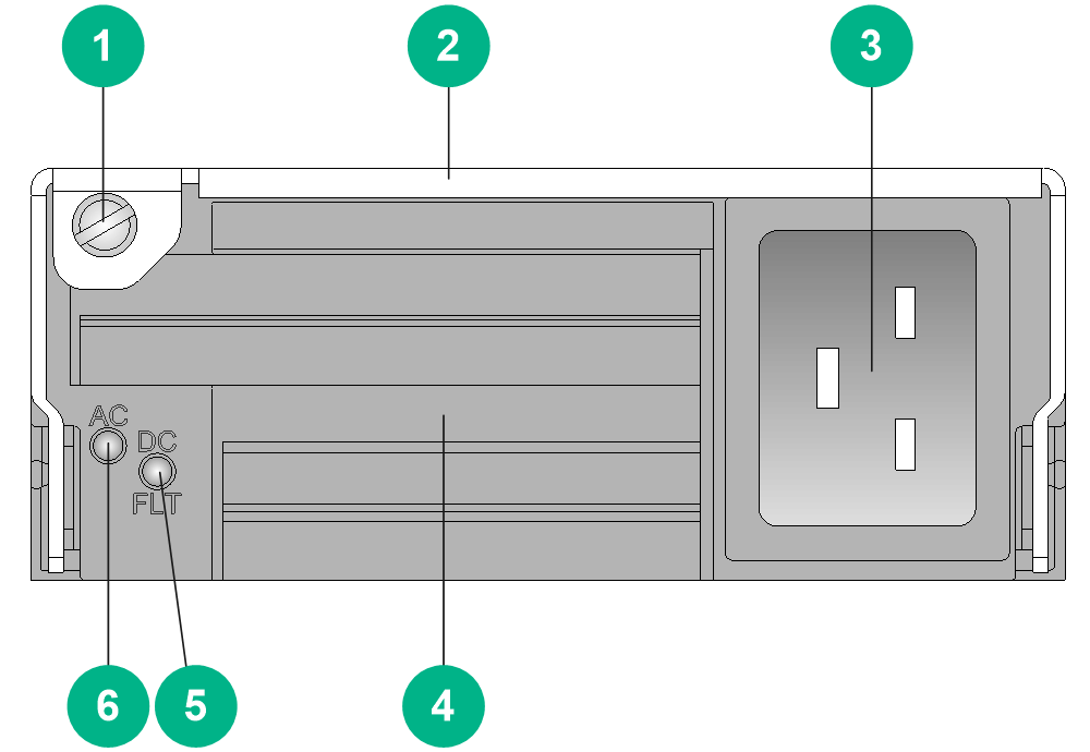
Front panel
|
(1) Captive screw |
(2) Handle |
|
(3) Power input receptacle |
(4) Air inlet grill |
|
(5) Power output status LED |
(6) Power input status LED |
|
|
CAUTION: · Remove any objects that might obstruct air intake through the air inlet grill. · Prevent conductive particles such as dust and metal particles from entering the power supply through the air inlet grill. These particles might cause failure of the power supply. |
Technical specifications
Table 1 Technical specifications
|
Item |
Specification |
|
Rated input voltage range |
100 to 240 VAC @ 50/60 Hz |
|
Rated output voltage |
12 VDC |
|
Maximum input current |
16 A |
|
Maximum output current |
100 A |
|
Maximum output power |
1200 W |
|
Dimensions (H × W × D) |
41 × 102 × 391 mm (1.61 × 4.02 × 15.39 in) |
|
Operating temperature |
–10°C to +50°C (+14°F to +122°F) |
|
Storage temperature |
–40°C to +70°C (–40°F to +158°F) |
LEDs
The power supply uses a power input status LED and power output status LED to indicate its operating status.
Table 2 LED description
|
LED |
Mark |
Status |
Description |
|
Power input status LED |
AC |
Off |
No power input. |
|
Input undervoltage has occurred, and the device has entered self-protection mode. |
|||
|
Green |
Normal power input. |
||
|
Power output LED |
DC |
Green |
Normal power output. |
|
Red |
One of the following output anomalies has occurred and the power supply has entered self-protection mode. · Output short-circuit · Output overcurrent · Output overvoltage · Input undervoltage · Overtemperature · Remote shutdown |
||
|
Orange |
A high temperature alarm is present, and the power supply has entered self-protection mode. |
|
|
NOTE: · The power output LED on a power supply is red when it has no power input or its connected circuit breaker is off but another power supply provides power to the device. · After the circuit breaker of the power supply is switched off, the input status LED on the power supply will remain on for a while. |
Power supply configuration guidelines
Determine the number of power supplies based on the system power consumption and the power supply configuration based on the power input mode.
· In an environment with two mains power inputs, configure N+N power supply redundancy.
· In an environment with only one mains power input, configure N+1 or N+N power supply redundancy.
· Provide a circuit breaker for power input of each power supply. Make sure each circuit breaker has a current rating not less than 20 A.
|
|
NOTE: The value of N depends on the number of power supply slots in the device. N+1 or N+N must not be greater than the total number of power supply slots. |
Installing and removing the power supply
Installing the power supply
To avoid possible damage, strictly follow the procedure in Figure 2 to install the power supply.
Figure 2 Power supply installation procedure
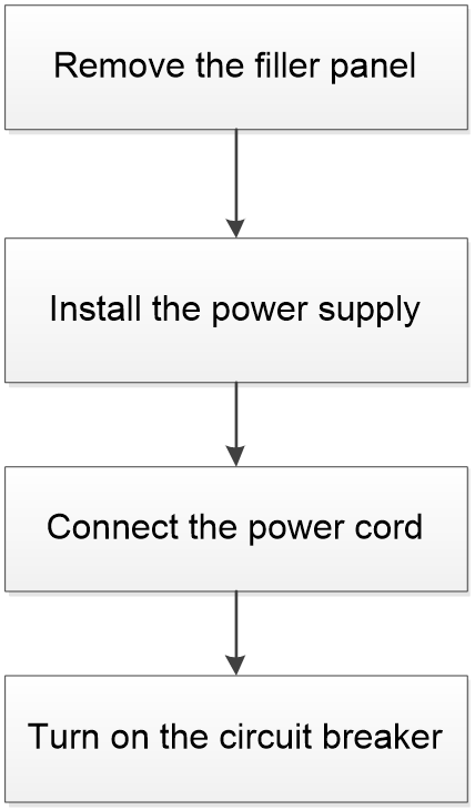
Before the installation, prepare an ESD wrist strap and a Phillips screwdriver yourself.
Installing the power supply
To install the power supply:
1. Wear an ESD wrist strap, and make sure the strap makes good skin contact and is reliably grounded.
2. Remove the filler panel, if any, from the power supply slot.
The device requires a minimum of one power supply to supply power so it comes with one slot that does not have a filler panel installed. If you install the power supply in this slot, skip this step.
3. Unpack the power supply.
4. Use the Phillips screwdriver to loosen the captive screw on the power supply handle and then pull the handle outward.
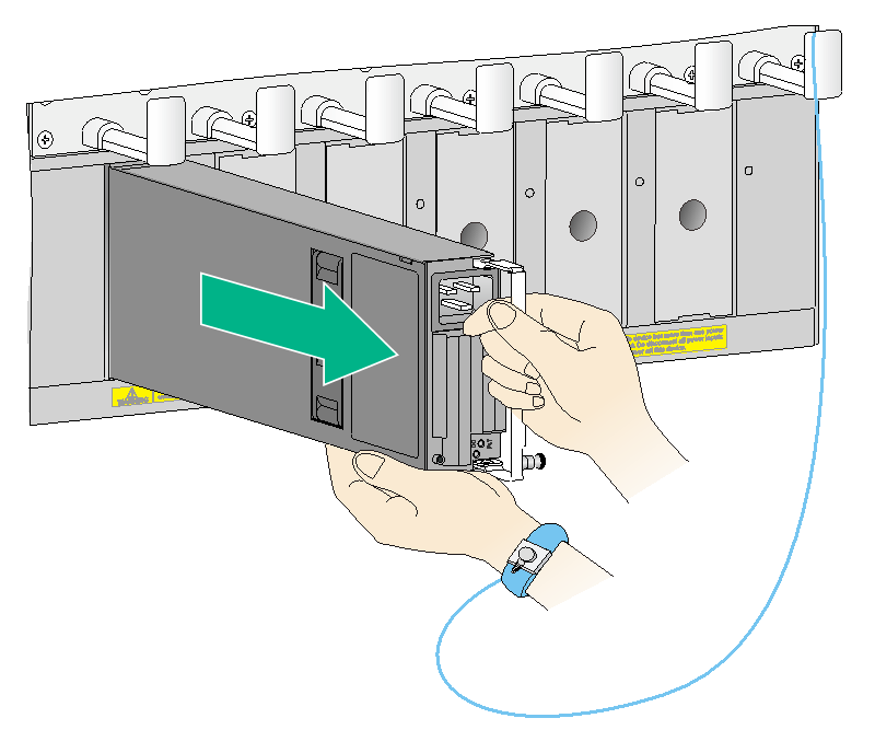
5. Correctly orient the power supply. Holding the power supply handle with one hand and supporting its bottom with the other, push the power supply slowly into the slot along the guide rails.
A power supply slot can be vertical or horizontal. The power supply installation method is similar for vertical and horizontal power supply slots. This procedure installs the power supply in a vertical slot.
Figure 3 Install the power supply

6. Press the handle back into the notch of the power supply.
7. Use the Phillips screwdriver to fasten the captive screw on the handle to secure the power supply to the chassis.
Connecting the power cord
|
|
WARNING! · Provide a separate circuit breaker for each power cord. · Turn off the circuit breaker before connecting a power cord. |
To connect the power cord:
1. Insert the AC power cord connector into the power input receptacle on the power supply.
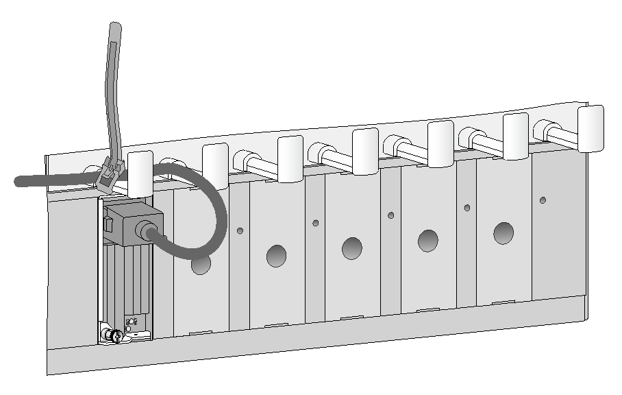
2. Use a releasable cable tie to secure the power cord to the power cord management bracket.
The power cord management bracket location varies by product. Route the power cord as required. The power cord securing method in Figure 4 is used as an example.
Figure 4 Securing the power cord
3. Connect the other end of the power cord to a power outlet of the AC power supply system and then turn on the circuit breaker.
4. Observe the power input status LED on the power supply. If the LED is on, the power cord is connected correctly. If the LED is not on, check the installation and locate and resolve any faults.
Removing the power supply
To avoid possible damage, strictly follow the procedure in Figure 5 to remove the power supply.
Figure 5 Power supply removal procedure
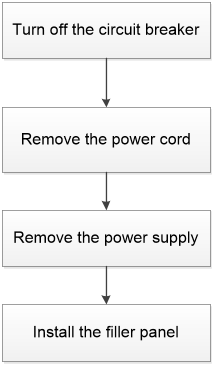
Before removing a power supply, prepare an ESD wrist strap and a Phillips screwdriver yourself.
Removing the power cord
1. Turn off the circuit breaker switch for the power supply.
After the circuit breaker switch for the power supply is turned off, the input status LED on the power supply will remain on for a while.
2. Wear an ESD wrist strap, and make sure the strap makes good skin contact and is reliably grounded.
3. Remove the releasable cable tie from the power cord and then remove the power cord connector from the power input receptacle.
Removing the power supply
1. Use the Phillips screwdriver to loosen the captive screw on the power supply handle.
2. Hold the captive screw on the handle and then pull the handle outward.
Figure 6 Removing the power supply
4. Put the removed power supply on an antistatic mat.
5. Install the filler panel back in the power supply slot, and fasten the captive screws on the filler panel.
The device requires a minimum of one power supply to supply power so it comes with one slot that does not have a filler panel installed. If you remove the power supply from this slot, skip this step.
|
|
CAUTION: Before inserting a removed power supply into a power supply slot, make sure both LEDs on the power supply are off. |
