- Table of Contents
- Related Documents
-
| Title | Size | Download |
|---|---|---|
| 04-Link Load Balancing Configuration Examples | 5.53 MB |
Link Load Balancing Configuration Examples
Copyright © 2022 New H3C Technologies Co., Ltd. All rights reserved
No part of this manual may be reproduced or transmitted in any form or by any means without prior written consent of New H3C Technologies Co., Ltd.
Except for the trademarks of New H3C Technologies Co., Ltd., any trademarks that may be mentioned in this document are the property of their respective owners.
The information in this document is subject to change without notice.
Contents
Link load balancing configuration examples
Example: Configuring ISP- and source IP-based link load balancing
Example: Configuring bandwidth algorithm-based link load balancing
Example: Configuring application recognition-based link load balancing
Example: Configuring domain-name and time-range based link load balancing
Example: Configuring proximity-based link load balancing
Example: Configuring link protection-based link load balancing
Example: Configuring PPPoE-based link load balancing
Example: Configuring intelligent link selection based on packet loss ratio
Example: Configuring ISP auto update-based link load balancing
Transparent DNS proxy configuration examples
Intelligent DNS configuration examples
Example: Configuring intelligent DNS based on DNS records
Example: Configuring dynamic proximity-based intelligent DNS
Example: Configuring static proximity-based intelligent DNS (virtual service)
Example: Configuring inbound link load balancing based on virtual service pool
Introduction
The following information provides examples of link load balancing and intelligent DNS.
Prerequisites
The following information applies to Comware 7-based LB devices. Procedures and information in the examples might be slightly different depending on the software or hardware version of the device.
The configuration examples were created and verified in a lab environment, and all the devices were started with the factory default configuration. When you are working on a live network, make sure you understand the potential impact of every command on your network.
The following information is provided based on the assumption that you have basic knowledge of load balancing.
Link load balancing configuration examples
Overview
Link load balancing applies to a network environment where there are multiple carrier links to implement dynamic link selection. This enhances link utilization.
Link load balancing supports IPv4 and IPv6, but does not support IPv4-to-IPv6 packet translation.
The configuration of the link load balancing feature is the same on an LB device and a firewall.
Example: Configuring ISP- and source IP-based link load balancing
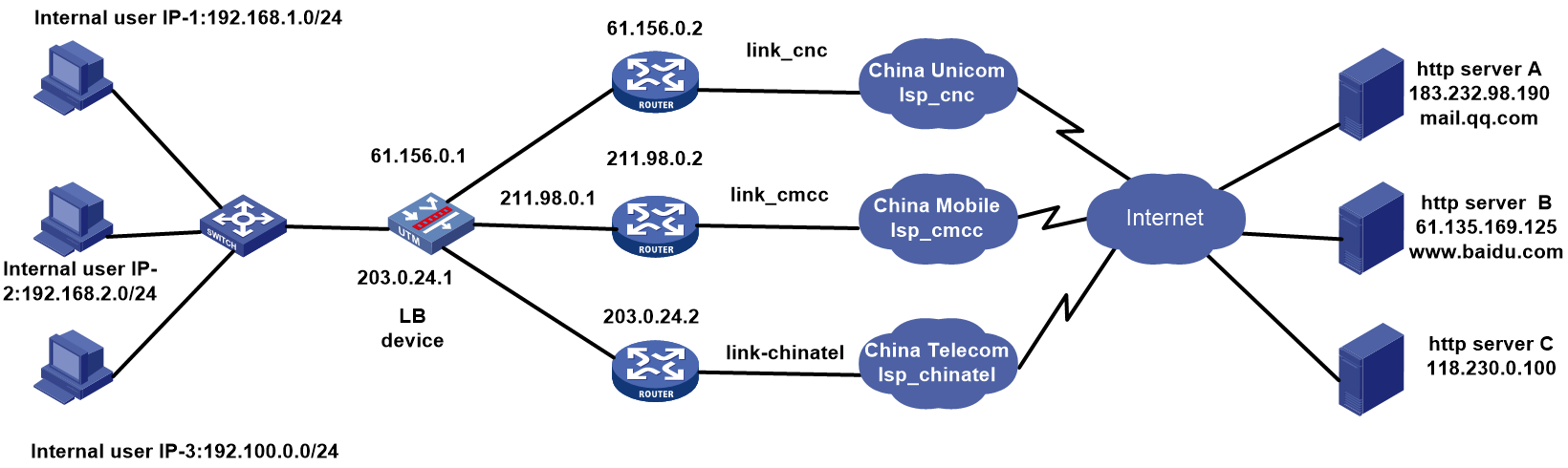
Network configuration
As shown in Figure 1, the three ISPs provide three links. Configure ISP- and source IP-based link load balancing to meet the following requirements:
· Packets with a destination IP address that matches ISPs cnc, cmcc, and chinatel are sent from the links in link groups lg-cnc, lg-cmcc, and lg-chinatel, respectively and NAT is performed
· The internal users in the 192.100.0.0/24 segment access the external server through link link-chinatel.

Analysis
For ISP- and source IP-based link load balancing, complete the following tasks:
· Configure match rules for the class of the link-generic type to match the ISP and source IP address.
· Apply a NAT address group to the outgoing interface of the LB device to protect the internal network.
· Configure an ICMP-type health monitoring template for each link, specify the next hop address as that for the link and the outgoing interface in the health monitoring template, and associate this health monitoring template for the link.
· Configure a routing policy on the LB device for packets with a source IP address in the 192.100.0.0/24 segment are sent from link lg-chinatel, and packets with a destination IP address that matches ISPs cnc, cmcc, and chinatel are sent from links lg-cnc, lg-cmcc, and lg-chinatel, respectively.
Software version used
This configuration example was created and verified on Alpha 1160P16 of L1000-AK325.
Restrictions and guidelines
When you configure ISP- and source IP-based link load balancing, follow these restrictions and guidelines:
· Import the most recent ISP file:
a. Access the H3C website at http://www.h3c.com/.
b. Navigate to the Support > Resource Center > Software Download > Security > Load Balancing > Comware V7 series > H3C ISP File page to download the file. After download, this file can be imported. Alternatively, you can upload an ISP file, and import the file by executing the loadbalance isp file command at the CLI to import the file to the device.
· Make sure the internal users and LB devices and internal users and the external server are reachable to each other.
Procedure
Assigning IP addresses to interfaces
Details not shown.
Importing an ISP file
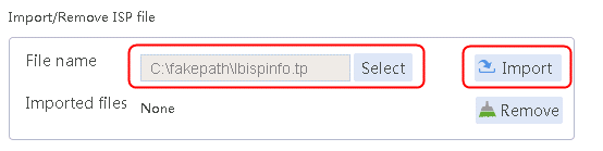
1. Navigate to the LB > Global Configuration > LSP page, click Select, select an ISP file, and then click Import.
Figure 2 Importing an ISP file

2. Click Import.
Configuring a health monitoring template of the ICMP type
1. Navigate to the LB > Global Configuration > Health Monitoring page, and then click Create.
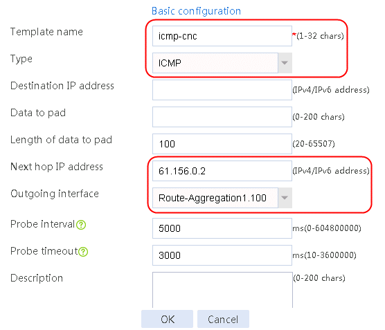
Figure 3 Creating health monitoring template icmp-cnc of the ICMP type
2. Click OK.
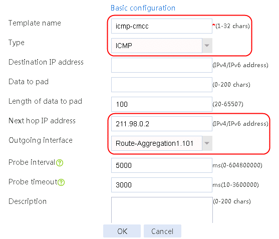
Figure 4 Creating health monitoring template icmp-cmcc of the ICMP type
3. Click OK.
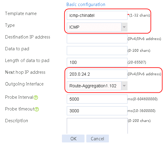
Figure 5 Creating health monitoring template icmp-chinatel of the ICMP type

4. Click OK.
Creating a link group
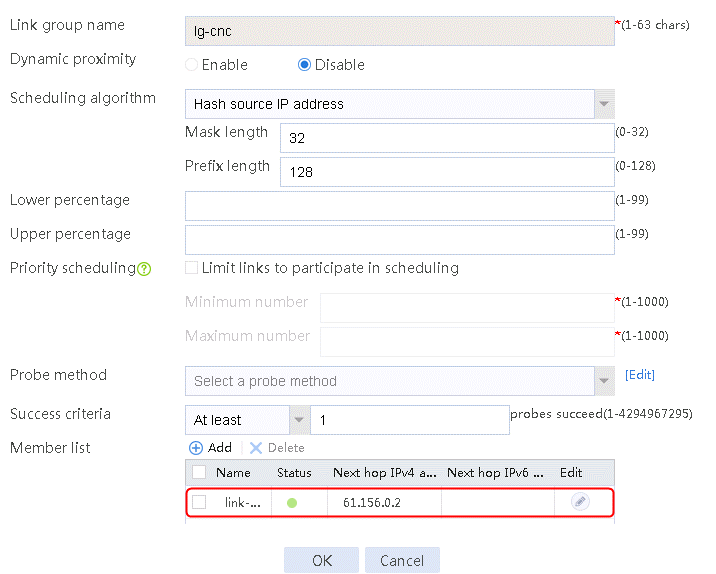
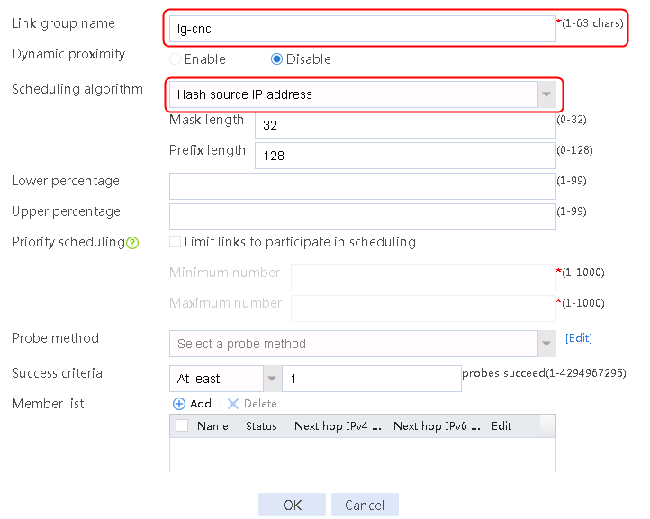
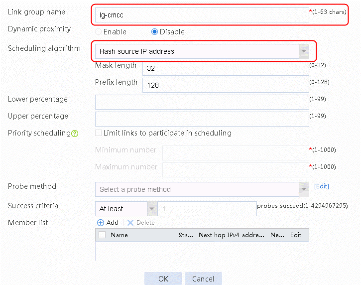
1. Navigate to the LB > Link Load Balancing > Out Link Load Balancing > Link Group page, and then click Create to create a link group named lg-cnc, with the scheduling algorithm of source IP address hash.
Figure 6 Creating link group lg-cnc

2. Click OK.
3. Create link groups lg-cmcc and lg-chinatel in the same way link group lg-cnc is created.
Configuring links
1. Navigate to the LB > Link Load Balancing > Out Link Load Balancing > Link Group page.
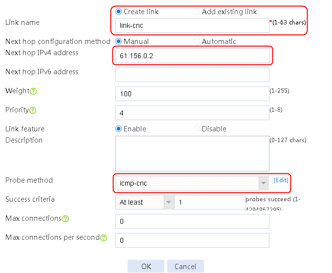
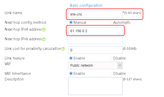
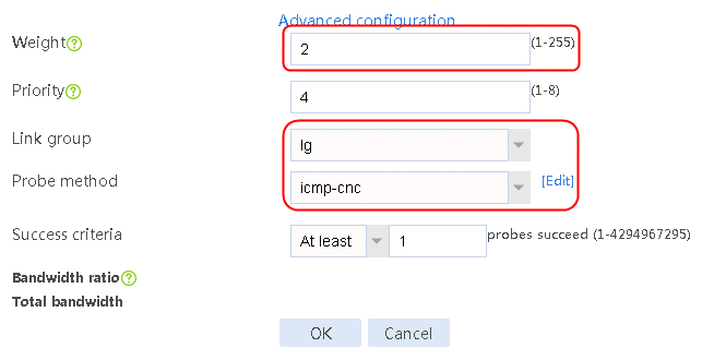
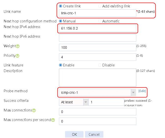
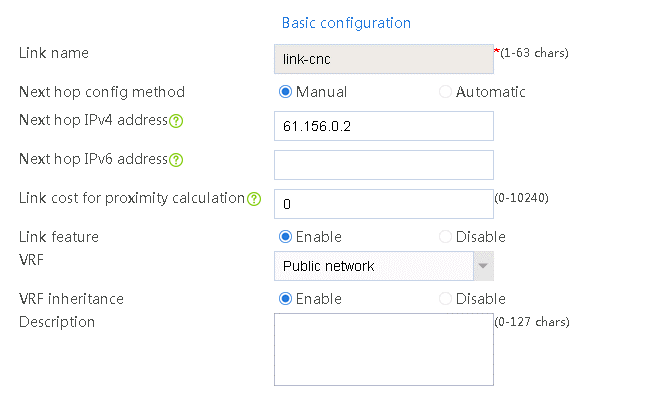
2. Edit link group lg-cnc and click Add to create a member list. Create link link-cnc, and configure the next hop IP address as 61.156.0.2 and the probe method as icmp-cnc.
Figure 7 Adding a link group member

Figure 8 Creating a link
3. Click OK.
Figure 9 Link information

4. Click OK.
5. Create links link-cmcc and link-chinatel in the same way link link-cnc is created.
Enabling load balancing
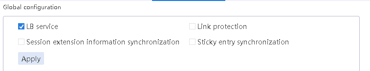
1. Navigate to the LB > Link Load Balancing > Out Link Load Balancing > IPv4 Routing Policy page, and select LB service in the Global Configuration area.
Figure 10 Enabling load balancing

2. Click Apply.
Configuring a class
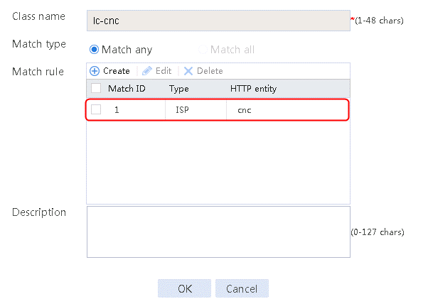
1. Navigate to the LB > Link Load Balancing > Out Link Load Balancing > Class page, and then click Create.
2. Specify the class name as lc-cnc, and the match type as Match any. Create a match rule, and set the match ID to 1, the type to ISP, and the HTTP entity to cnc.
Figure 11 Creating a class

3. Click OK.
Figure 12 Class information

4. Click OK.
5. Create classes lc-cmcc, lc-chinatel, and lc-source in the same way class lc-cnc is created.
Configuring an IPv4 routing policy
1. Navigate to the LB > Link Load Balancing > Out Link Load Balancing > IPv4 Routing Policy page, and then click Create.
2. Create IPv4 routing policy 1, select lc-cnc for the class, Load Balancing for the forwarding mode, lg-cnc for the primary link group, and select Match next rule for the fallback action.
Figure 13 Creating IPv4 routing policy 1

3. Click OK.
4. Create other IPv4 routing policies in the same way IPv4 routing policy 1 is created.
Creating a NAT address group and applying it to the link outgoing interface
1. Navigate to the Object > Object Group > NAT Address Group page, and then click Create.
2. Specify the address group number as 1 and the address group name as cnc. Click Add and set the start and end IP addresses of the new address group members to 61.156.0.100 and 61.156.0.200, respectively.
Figure 14 Creating address group 1

3. Click OK.
Figure 15 Address group 1 information

4. Click OK.
5. Create address groups 2 and 3 in the same way address group 1 is created.
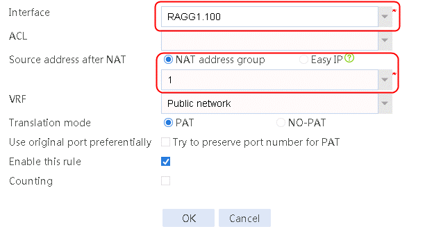
6. Navigate to the Network > NAT > IPv4 > Dynamic NAT page, and then click Create to create a dynamic NAT policy. Select outgoing interface RAGG1.100 that corresponds to the link next hop address, and select NAT address group 1 for source address after NAT.
Figure 16 Creating dynamic NAT policy 1
7. Click OK.
8. Create dynamic NAT policy 2 and dynamic NAT policy 3 in the same way dynamic NAT policy 1 is created.
Verifying the configuration
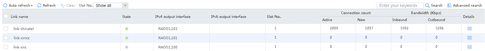
1. Use the client to send packets that match source IP address range 192.100.0.0/24, class lc-chinatel, and link group lg-chinatel.
2. Navigate to the Monitor > Link Load Balancing > Links > Real-time Statistics page to view the link statistics to verify that the link-chinatel link has statistics.
Figure 17 Viewing statistics about the link with the matching source IP address of 192.100.0.0/24
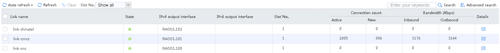
3. Use the client to send packets with a destination IP address matching ISP cmcc. The matching class is lc-cmcc and the link group is lg-cmcc. Verify that the link has statistics.
Figure 18 Viewing statistics about the link matching ISP cmcc
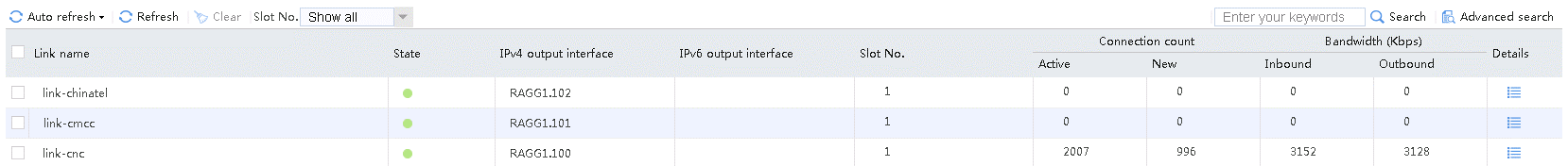
4. Use the client to send packets with a destination IP address matching ISP cnc. The matching class is lc-cnc, and the link group is lg-cnc. Verify that the link has statistics.
Figure 19 Viewing statistics about the link matching ISP cnc

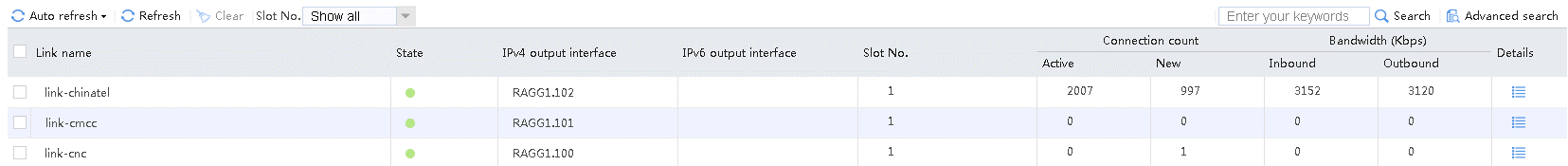
5. Use the client to send packets with a destination IP address matching ISP chinatel. The matching class is lc-chinatel, and the link group is lg-chinatel. Verify that the link has statistics.
Figure 20 Viewing statistics about the link matching ISP chinatel
6. Use a tester to send packets with a destination IP address matching ISP educn. Because the packets do not match the configured class, the packets are sent from link group lg-cnc. Verify that the link has statistics.
Figure 21 Viewing statistics about the link matching ISP educn
Configuration files
#
loadbalance isp file flash:/lbispinfo.tp
#
nqa template icmp icmp-cnc
next-hop ip 61.156.0.2
out interface Route-Aggregation1.100
#
nqa template icmp icmp-cmcc
next-hop ip 211.98.0.2
out interface Route-Aggregation1.101
#
nqa template icmp icmp-chinatel
next-hop ip 203.0.24.2
out interface Route-Aggregation1.102
#
loadbalance link-group lg-chinatel
predictor hash address source
transparent enable
success-criteria at-least 1
link link-chinatel
success-criteria at-least 1
probe icmp-chinatel
#
loadbalance link-group lg-cmcc
predictor hash address source
transparent enable
success-criteria at-least 1
link link-cmcc
success-criteria at-least 1
probe icmp-cmcc
#
loadbalance link-group lg-cnc
predictor hash address source
transparent enable
success-criteria at-least 1
link link-cnc
success-criteria at-least 1
probe icmp-cnc
#
loadbalance link link-chinatel
router ip 203.0.24.2
probe icmp-chinatel
#
loadbalance link link-cmcc
router ip 211.98.0.2
probe icmp-cmcc
#
loadbalance link link-cnc
router ip 61.156.0.2
probe icmp-cnc
#
loadbalance class lc-chinatel type link-generic match-any
match 1 isp chinatel
#
loadbalance class lc-cmcc type link-generic match-any
match 1 isp cmcc
#
loadbalance class lc-cnc type link-generic match-any
match 1 isp cnc
#
loadbalance class lc-source type link-generic match-any
match 1 source ip address 192.100.0.0 24
#
loadbalance action ##defaultactionforllbipv4##%%autocreatedbyweb%% type link-gen
eric
link-group lg-cnc
#
loadbalance action ob$action$#for#lc-chinatel type link-generic
link-group lg-chinatel
fallback-action continue
#
loadbalance action ob$action$#for#lc-cmcc type link-generic
link-group lg-cmcc
fallback-action continue
#
loadbalance action ob$action$#for#lc-cnc type link-generic
link-group lg-cnc
fallback-action continue
#
loadbalance action ob$action$#for#lc-source type link-generic
link-group lg-chinatel
fallback-action continue
#
loadbalance policy ##defaultpolicyforllbipv4##%%autocreatedbyweb%% type link-gen
eric
class lc-cnc action ob$action$#for#lc-cnc
class lc-cmcc action ob$action$#for#lc-cmcc
class lc-chinatel action ob$action$#for#lc-chinatel
class lc-source action ob$action$#for#lc-source
default-class action ##defaultactionforllbipv4##%%autocreatedbyweb%%
#
virtual-server ##defaultvsforllbipv4##%%autocreatedbyweb%% type link-ip
virtual ip address 0.0.0.0 0
lb-policy ##defaultpolicyforllbipv4##%%autocreatedbyweb%%
bandwidth interface statistics enable
service enable
#
nat address-group 1 name cnc
address 61.156.0.100 61.156.0.200
#
nat address-group 2 name cmcc
address 211.98.0.100 211.98.0.200
#
nat address-group 3 name chinatel
address 203.0.24.100 203.0.24.200
#
interface Route-Aggregation1.100
ip address 61.156.0.1 255.255.255.0
nat outbound address-group 1
#
interface Route-Aggregation1.101
ip address 211.98.0.1 255.255.255.0
nat outbound address-group 2
#
interface Route-Aggregation1.102
ip address 203.0.24.1 255.255.255.0
nat outbound address-group 3
#
Example: Configuring bandwidth algorithm-based link load balancing
Network configuration
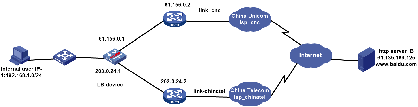
As shown in the Figure 22, the two ISPs provide two links. Configure bandwidth algorithm-based link load balancing for the traffic to access the external server to be load balanced on two links based on the bandwidth algorithm. With the bandwidth value and weight value configured for each link, the LB device distributes the traffic to the corresponding links as configured.
Analysis
For bandwidth algorithm-based link load balancing, complete the following tasks:
· Configure a bandwidth scheduling algorithm with different link bandwidths and the same weight. View statistics about the link. The traffic is load balanced based on the remaining bandwidth ratio.
· Configure a bandwidth scheduling algorithm with the same link bandwidth and different weights. View statistics about the link. The traffic is load balanced based on the configured weights.
· With a bandwidth scheduling algorithm configured, an LB device uses the calculated bandwidth. If interface bandwidth statistics collection is enabled for the link, the interface bandwidth for the link is used.
· Configure an ICMP-type health monitoring template for each link, specify the next hop address as that for the link and the outgoing interface in the health monitoring template, and associate this health monitoring template for the link.
· Apply a NAT address group to the outgoing interface of the LB device to protect the internal network.
· Create a link group named lg, and assign links link-chinatel and link-cnc to that link group.
Software version used
This configuration example was created and verified on Alpha 1160P16 of L1000-AK325.
Procedure
Assigning IP addresses to interfaces
Details not shown.
Configuring a health monitoring template of the ICMP type
1. Navigate to the LB > Global Configuration > Health Monitoring page, and then click Create.
Figure 23 Creating health monitoring template icmp-cnc of the ICMP type

2. Click OK.
Figure 24 Creating health monitoring template icmp-chinatel of the ICMP type

3. Click OK.
Creating link group lg
1. Navigate to the LB > Link Load Balancing > Out Link Load Balancing > Link Group page, and then click Create. Specify the link group name as lg and the scheduling algorithm as Bandwidth.
Figure 25 Creating link group lg

2. Click OK.
Configuring links
Configure links with different bandwidths and the same weight:
1. Navigate to the LB > Global Configuration > Links page and then click Create.
2. Configure the following settings:
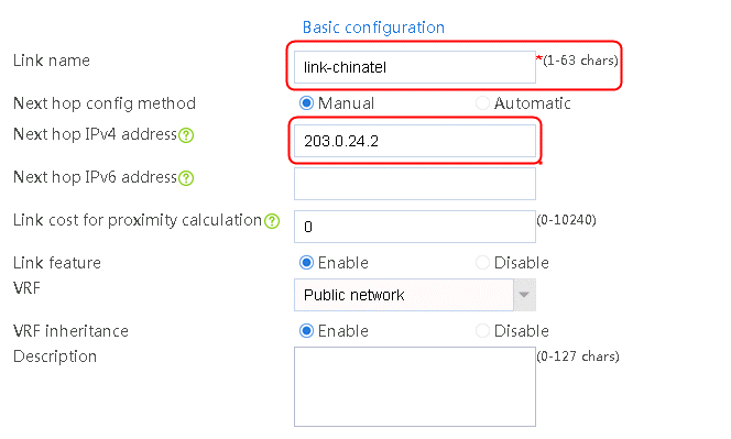
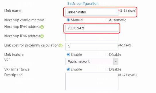
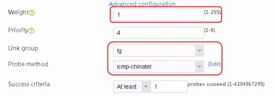
a. Specify the link name as link-chinatel.
b. Configure the next hop address as 203.0.24.2.
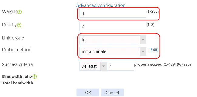
c. Specify the weight as 1.
d. Specify the link group as lg.
e. Specify the probe method as icmp-chinatel.
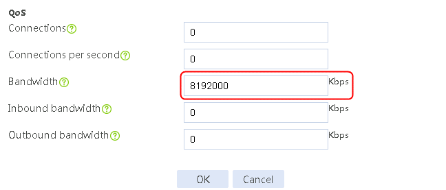
f. Specify the maximum rate-limiting bandwidth as 8192000 Kbps.
Figure 26 Creating link link-chinatel
3. Click OK.
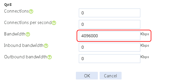
4. Click Create. Create link link-cnc, and configure the next hop address as 61.156.0.2, the weight as 1, the link group as lg, the probe method as icmp-cnc, and the maximum rate-limiting bandwidth as 4096000 Kbps.
Figure 27 Creating link link-cnc


5. Click OK.
Configure links with the same link bandwidth and different weights:
1. Navigate to the LB > Global Configuration > Links page. Create link link-chinatel, and configure the next hop address as 203.0.24.2, the weight as 1, the link group as lg, the probe method as icmp-chinatel, and the maximum rate-limiting bandwidth as 8192000 Kbps.
Figure 28 Creating link link-chinatel
2. Click OK.
3. Click Create. Create link link-cnc, and configure the next hop address as 61.156.0.2, the weight as 2, the link group as lg, the probe method as icmp-cnc, and the maximum rate-limiting bandwidth as 8192000 Kbps.
Figure 29 Creating link link-cnc

4. Click OK.
Enabling load balancing
1. Navigate to the LB > Link Load Balancing > Out Link Load Balancing > IPv4 Routing Policy page, and then select LB service in the Global Configuration area.
Figure 30 Enabling load balancing
2. Click Apply.
Creating an IPv4 routing policy
1. Navigate to the LB > Link Load Balancing > Out Link Load Balancing > IPv4 Routing Policy page, and then click Create. Configure the default forwarding mode as Load Balance and the primary link group as lg.
Figure 31 Creating a default IPv4 routing policy

2. Click OK.
Creating a NAT address group and applying it to the link outgoing interface
1. Navigate to the Object > Object Group > NAT Address Group page, and then click Create. Specify the address group number as 1 and the address group name as cnc. Click Add and set the start and end IP addresses of the new address group members to 61.156.0.100 and 61.156.0.200, respectively.
Figure 32 Creating address group 1

2. Click OK.
Figure 33 Address group 1 information

3. Click OK.
4. Create address group 3 in the same way address group 1 is created.
5. Navigate to the Network > NAT > IPv4 > Dynamic NAT page, and then click Create to create a dynamic NAT policy. Select outgoing interface RAGG1.100 that corresponds to the link next hop address, and select NAT address group 1 for source address after NAT.
Figure 34 Creating dynamic NAT policy 1

6. Click OK.
7. Create dynamic NAT policy 3 in the same way dynamic NAT policy 1 is created.
Verifying the configuration
1. With different link bandwidths and the same weight configured: Enable internal users to access the server, and then view traffic statistics about the two links. The ratio of traffic on the two links is 2:1.
Figure 35 Link statistics with different bandwidths and the same weight
![]()
2. With the same link bandwidth and different weights configured: Enable internal users to initiate requests to the server, and view the traffic statistics about the two links. The ratio of traffic on the two links is 1:2.
Figure 36 Link statistics with the same bandwidth and different weights

Configuration files
#
nqa template icmp icmp-cnc
next-hop ip 61.156.0.2
out interface Ten-GigabitEthernet1/1/0
#
nqa template icmp icmp-chinatel
next-hop ip 203.0.24.2
out interface Ten-GigabitEthernet1/1/2
#
loadbalance link-group lg
predictor bandwidth
transparent enable
success-criteria at-least 1
#
Link configuration with different bandwidths and the same weight:
loadbalance link link-chinatel
router ip 203.0.24.2
link-group lg
weight 1
rate-limit bandwidth 8192000 Kbps
success-criteria at-least 1
probe icmp-chinatel
#
loadbalance link link-cnc
router ip 61.156.0.2
link-group lg
weight 1
rate-limit bandwidth 4096000 Kbps
success-criteria at-least 1
probe icmp-cnc
#
Link configuration with the same bandwidth and different weights:
#
loadbalance link link-chinatel
router ip 203.0.24.2
link-group lg
weight 1
rate-limit bandwidth 8192000 Kbps
success-criteria at-least 1
probe icmp-chinatel
#
loadbalance link link-cnc
router ip 61.156.0.2
link-group lg
weight 2
rate-limit bandwidth 8192000 Kbps
success-criteria at-least 1
probe icmp-cnc
#
loadbalance action ##defaultactionforllbipv4##%%autocreatedbyweb%% type link-gen
eric
link-group lg
#
loadbalance policy ##defaultpolicyforllbipv4##%%autocreatedbyweb%% type link-gen
eric
default-class action ##defaultactionforllbipv4##%%autocreatedbyweb%%
#
virtual-server ##defaultvsforllbipv4##%%autocreatedbyweb%% type link-ip
virtual ip address 0.0.0.0 0
lb-policy ##defaultpolicyforllbipv4##%%autocreatedbyweb%%
service enable
bandwidth interface statistics enable
#
nat address-group 1
address 61.156.0.100 61.156.0.200
#
nat address-group 3
address 203.0.24.100 203.0.24.200
#
interface Ten-GigabitEthernet1/1/0
port link-mode route
description link-cnc
ip address 61.156.0.1 255.255.255.0
nat outbound address-group 1
#
interface Ten-GigabitEthernet1/1/2
port link-mode route
description link-chintel
ip address 203.0.24.1 255.255.255.0
nat outbound address-group 3
#
Example: Configuring application recognition-based link load balancing
Network configuration
As shown in the Figure 37, the two ISPs provide two links. Configure application recognition-based link load balancing for the traffic to access the external server to be load balanced on links link-cnc and link-chinatel in link groups lg-cnc and lg-chinatel, respectively.

Analysis
For application recognition-based link load balancing, complete the following tasks:
· Create an application group, configure the FTP class for the application group, and configure a routing policy for the application traffic to be transmitted over link link-cnc and the default traffic is transmitted over link link-chinatel.
· Apply a NAT address group to the outgoing interface of the LB device to protect the internal network.
· Configure an ICMP-type health monitoring template for each link, specify the next hop address as that for the link and the outgoing interface in the health monitoring template, and associate this health monitoring template for the link.
Software version used
This configuration example was created and verified on Alpha 1160P16 of L1000-AK325.
Restrictions and guidelines
You can select multiple types of applications in an application group. In this example, only the FTP application is selected.
Procedure
Assigning IP addresses to interfaces
Details not shown.
Configuring a health monitoring template of the ICMP type
1. Navigate to the LB > Global Configuration > Health Monitoring page, and then click Create.
Figure 38 Creating health monitoring template icmp-cnc of the ICMP type

2. Click OK.
Figure 39 Creating health monitoring template icmp-chinatel of the ICMP type

3. Click OK.
Creating link groups
1. Navigate to the LB > Link Load Balancing > Out Link Load Balancing > Link Group page, and then click Create. Specify the link group name as lg-cnc, and the scheduling algorithm as source IP address hash.
Figure 40 Creating link group lg-cnc

2. Click OK.
3. Create link group lg-chinatel in the same way link group lg-cnc is created.
Configuring links
1. Navigate to the LB > Link Load Balancing > Out Link Load Balancing > Link Group page.
2. Edit link group lg-cnc and click Add to create a member list. Create link link-cnc, and configure the next hop IP address as 61.156.0.2 and the probe method as icmp-cnc.
Figure 41 Adding a link group member
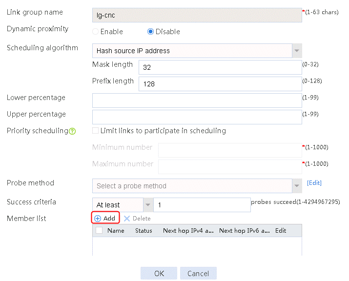
Figure 42 Creating a link

3. Click OK.
Figure 43 Link information
4. Click OK.
5. Create link link-chinatel in the same way link link-cnc is created.
Configuring an application group
1. Navigate to the LB > Application Security > Application Recognition > Application Groups page, and then click Create.
Figure 44 Creating an application group and selecting the FTP application
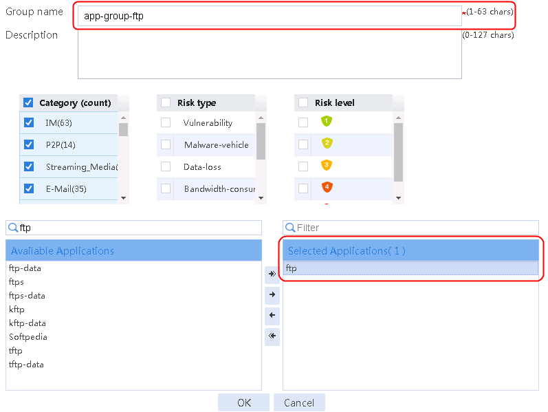
2. Click OK.
Enabling load balancing
1. Navigate to the LB > Link Load Balancing > Out Link Load Balancing > IPv4 Routing Policy page, and then select LB service in the Global Configuration area.
Figure 45 Enabling load balancing

2. Click Apply.
Configuring a class
1. Navigate to the LB > Link Load Balancing > Out Link Load Balancing > Class page, and then click Create. Specify the class name as lc-cnc, and the match type as Match any. Create a match rule, and set the match ID to 1, the type to Application Group, and the HTTP entity to app-group-ftp.
Figure 46 Creating class lc-cnc
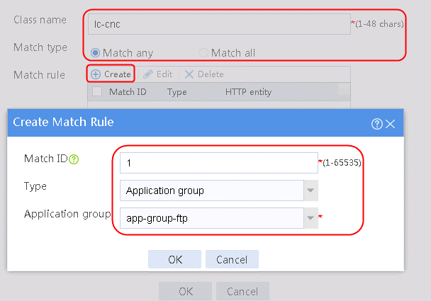
2. Click OK.
Figure 47 Class information
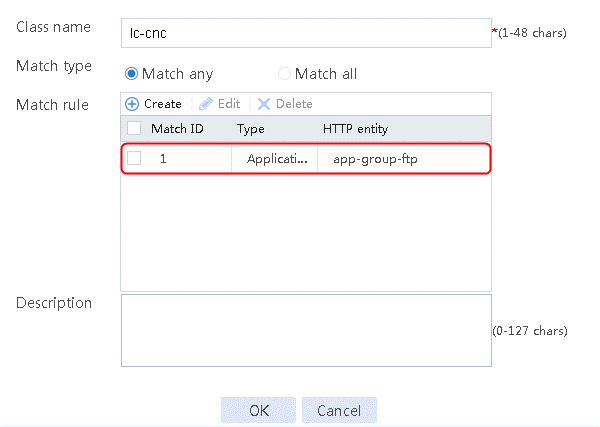
3. Click OK.
Configuring an IPv4 routing policy
1. Navigate to the LB > Link Load Balancing > Out Link Load Balancing > IPv4 Routing Policy page, and then click Create.
2. Create an IPv4 routing policy, select lc-cnc for the class, Load Balancing for the forwarding mode, lg-cnc for the primary link group, and select Match next rule for the fallback action.
Figure 48 Creating an IPv4 routing policy
3. Click OK.
Figure 49 Configuring the default action

4. Click OK.
Creating a NAT address group and applying it on the link outgoing interface
1. Navigate to the Object > Object Group > NAT Address Group page, and then click Create. Specify the address group number as 1 and the address group name as cnc. Click Add and set the start and end IP addresses of the new address group members to 61.156.0.100 and 61.156.0.200, respectively.
Figure 50 Creating address group 1
2. Click OK.
Figure 51 Address group 1 information

3. Click OK.
4. Create address group 3 in the same way address group 1 is created.
5. Navigate to the Network > NAT > IPv4 > Dynamic NAT page, and then click Create to create a dynamic NAT policy. Select outgoing interface RAGG1.100 that corresponds to the link next hop address, and select NAT address group 1 for source address after NAT.
Figure 52 Creating dynamic NAT policy 1

6. Click OK.
7. Create dynamic NAT policy 3 in the same way dynamic NAT policy 1 is created.
Verifying the configuration
1. Use the client to send FTP traffic that matches class lc-cnc from link group lg-cnc. Verify that the link-cnc link has statistics.
Figure 53 Link statistics for the FTP traffic sent by the client
![]()
2. Use the client to send non-FTP traffic (for example, HTTP traffic) that does not match class lc-cnc from the default link group lg-chinatel. Verify that the link-chinatel link has statistics.
Figure 54 Link statistics for the HTTP traffic sent by the client
![]()
Configuration files
#
nqa template icmp icmp-cnc
next-hop ip 61.156.0.2
out interface Ten-GigabitEthernet1/1/0
#
nqa template icmp icmp-chinatel
next-hop ip 203.0.24.2
out interface Ten-GigabitEthernet1/1/2
#
loadbalance link-group lg-cnc
predictor hash address source
transparent enable
link link-cnc
success-criteria at-least 1
probe icmp-cnc
#
loadbalance link-group lg-chinatel
predictor hash address source
transparent enable
link link-chinatel
success-criteria at-least 1
probe icmp-chinatel
#
loadbalance link link-cnc
router ip 61.156.0.2
#
loadbalance link link-chinatel
router ip 203.0.24.2
#
app-group app-group-ftp
description "User-defined application group"
include application ftp
#
loadbalance class lc-cnc type link-generic
match 1 app-group app-group-ftp
#
loadbalance action ob$action$#for#lc-cnc type link-generic
link-group lg-cnc
fallback-action continue
#
loadbalance action ##defaultactionforllbipv4##%%autocreatedbyweb%% type link-generic
link-group lg-chinatel
#
loadbalance policy ##defaultpolicyforllbipv4##%%autocreatedbyweb%% type link-generic
class lc-cnc action ob$action$#for#lc-cnc
default-class action ##defaultactionforllbipv4##%%autocreatedbyweb%%
#
virtual-server ##defaultvsforllbipv4##%%autocreatedbyweb%% type link-ip
virtual ip address 0.0.0.0 0
lb-policy ##defaultpolicyforllbipv4##%%autocreatedbyweb%%
service enable
bandwidth interface statistics enable
#
nat address-group 1
address 61.156.0.100 61.156.0.200
#
nat address-group 3
address 203.0.24.100 203.0.24.200
#
interface Ten-GigabitEthernet1/1/0
port link-mode route
description link-cnc
ip address 61.156.0.1 255.255.255.0
nat outbound address-group 1
#
interface Ten-GigabitEthernet1/1/2
port link-mode route
description link-chintel
ip address 203.0.24.1 255.255.255.0
nat outbound address-group 3
#
Example: Configuring domain-name and time-range based link load balancing
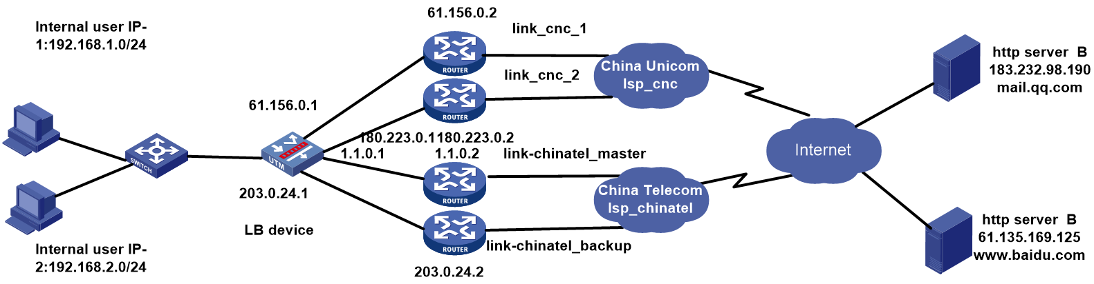
Network configuration
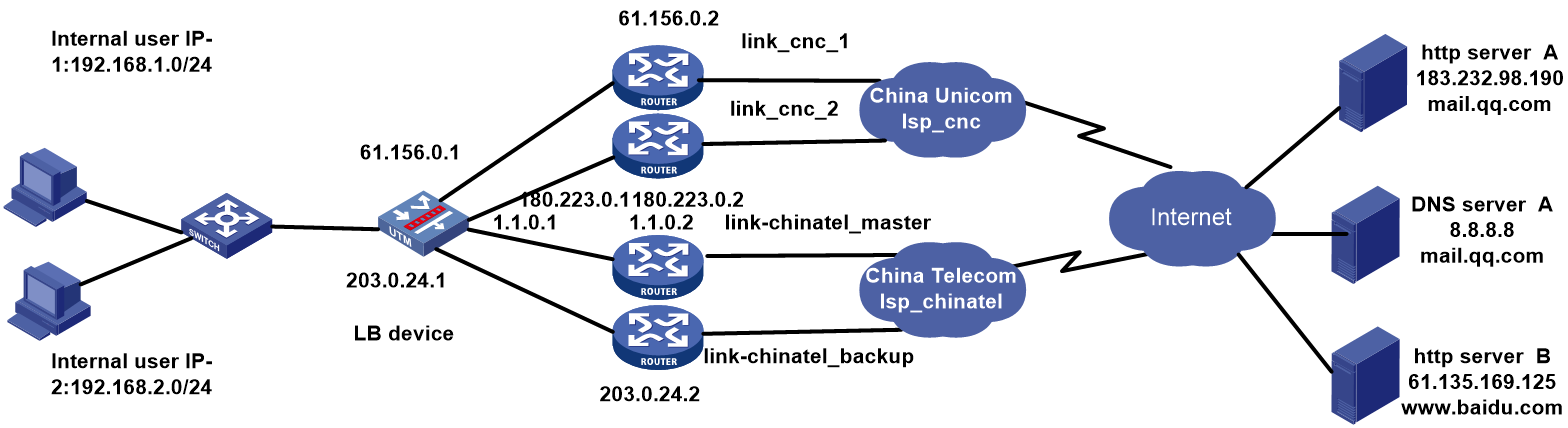
As shown in Figure 55, the two ISPs provide two public IP addresses. Configure domain-name and time-range based link load balancing to meet the following requirements:
· The internal users access the external network through China Unicom links, with China Telecom links as backup links during rush hours (Monday to Friday from 8am to 12pm and from 14pm to 18pm).
· The internal users access the external network through a higher-priority China Telecom IP address, with a China Unicom IP address as the backup during the low peak period.
· Use China Unicom the default egress interface, and that of China Telecom acts as the backup.
Analysis
For domain-name and time-range based load balancing, complete the following tasks:
· Configure match rules for the class of the link-generic type to match the destination domain names and time ranges, and select Match all for matching type.
· Configure NAT to protect the internal network.
· Configure an ICMP-type health monitoring template for each link, specify the next hop address as that for the link and the outgoing interface in the health monitoring template, and associate this health monitoring template for the link.
· Configure an LB policy of the link-generic type on the LB device. In the policy, configure the default action for packets that pass through the LB device for first time to be transmitted over the default link and for the packets that do not match any domain name to be load balanced without being dropped.
Software version used
This configuration example was created and verified on Alpha 1160P16 of L1000-AK325.
Restrictions and guidelines
When you configure domain-name and time-range based load balancing, follow these restrictions and guidelines:
· You can delete DNS Cache table entries manually.
· For domain name-based link load balancing to take effect, make sure the DNS request and response packets can be transmitted through the LB device and the DNS cache information can be generated on the LB device.
Procedure
Assigning IP addresses to interfaces
Details not shown.
Creating the health monitoring template of the ICMP type
1. Navigate to the LB > Global Configuration > Health Monitoring page, and then click Create.
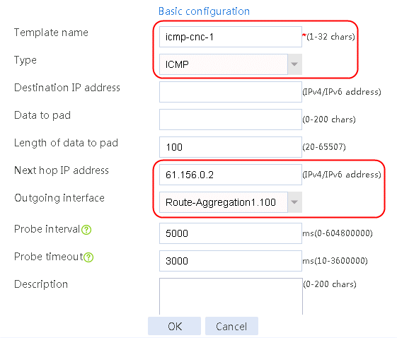
Figure 56 Configuring health monitoring template icmp-cnc-1 of the ICMP type

2. Click OK.
Figure 57 Configuring health monitoring template icmp-cnc-2 of the ICMP type

3. Click OK.
Figure 58 Configuring health monitoring template icmp-chinatel-master of the ICMP type

4. Click OK.
Figure 59 Configuring health monitoring template icmp-chinatel-backup of the ICMP type

5. Click OK.
Creating link groups
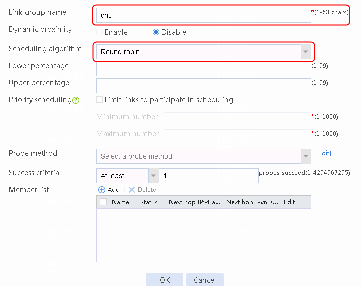
1. Navigate to the LB > Link Load Balancing > Out Link Load Balancing > Link Group page, and then click Create. Specify the link group name as cnc, and the scheduling algorithm as round robin.
Figure 60 Creating link group cnc
2. Click OK.
3. Create link group chinatel in the same way link group cnc is created.
Configuring links
1. Navigate to the LB > Link Load Balancing > Out Link Load Balancing > Link Group page.
2. Edit the link group cnc, and click Add to create a member list. Create link link-cnc-1, configure the next hop IP address as 61.156.0.2, and the probe method as icmp-cnc-1.
Figure 61 Adding a link group member
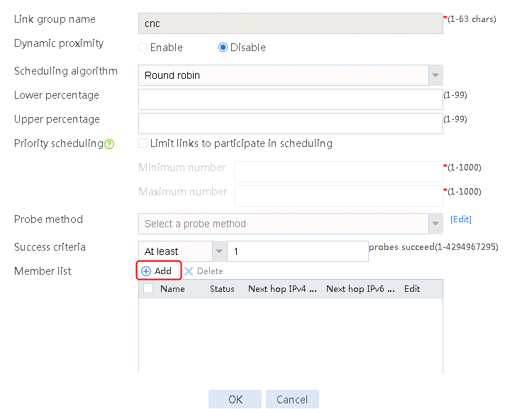
Figure 62 Creating link link-cnc-1

3. Click OK.
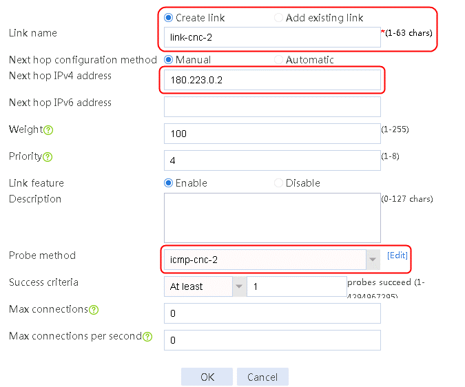
4. Click Add again to create a member list. Create link link-cnc-2, configure the next hop IP address as 180.223.0.2, and the probe method as icmp-cnc-2.
Figure 63 Creating link link-cnc-2
5. Click OK.
Figure 64 Link information
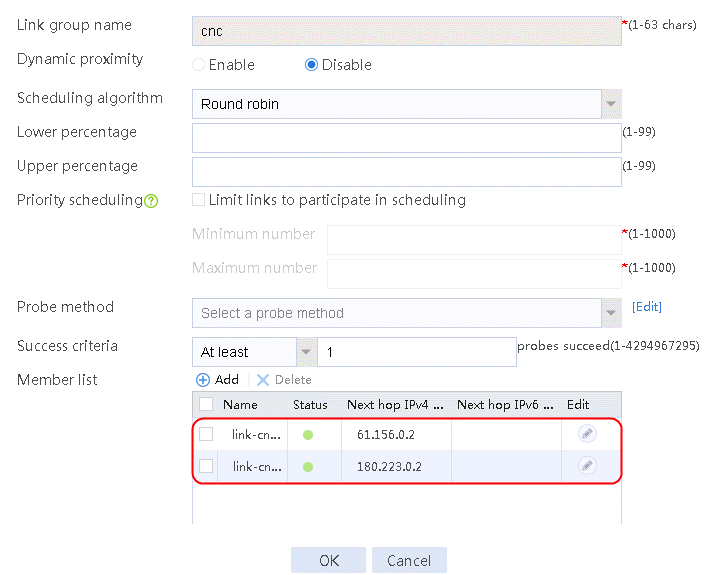
6. Click OK.
7. Create links link-chinatel-master and link-chinatel-backup in the same way links link-cnc-1 and link-cnc-2 are created.
Creating a time range and applying it in an ACL policy
1. Navigate to the Object > Object Group > Time Range page.
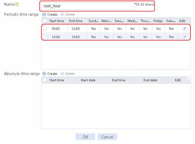
2. Click Create to create a time range named rush_hour.
Figure 65 Creating a time range
3. Click OK.
Figure 66 Creating time range low peak period
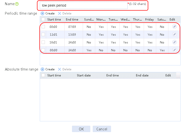
4. Click OK.
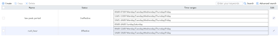
Figure 67 Viewing the time range configuration
5. Navigate to the Object > ACL > IPv4 ACL page, and then click Create to configure advanced ACL 3001 to match the rush_hour time range and advanced ACL 3002 to match the low peak period time range.
Figure 68 Creating ACL 3001
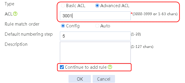
6. Click OK.
Figure 69 Configuring ACL 3001

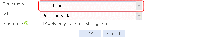
7. Click OK.
Figure 70 Creating ACL 3002
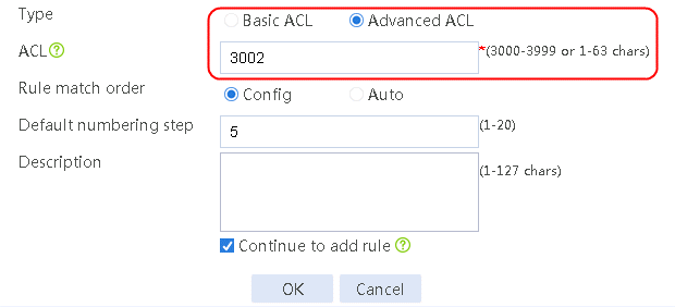
8. Click OK.
Figure 71 Configuring ACL 3002
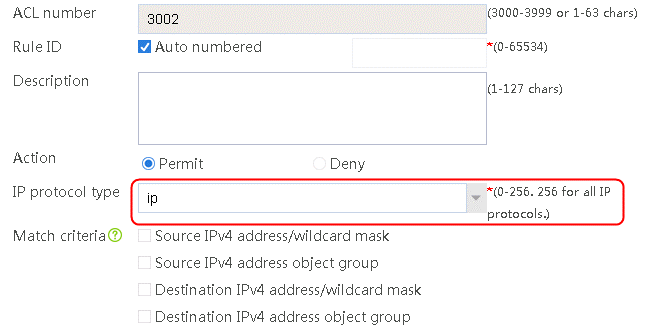

9. Click OK.
Enabling load balancing
1. Navigate to the LB > Link Load Balancing > Out Link Load Balancing > IPv4 Routing Policy page, and then select LB service in the Global Configuration area.
Figure 72 Enabling load balancing

2. Click Apply.
Configuring a class
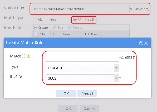
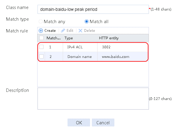
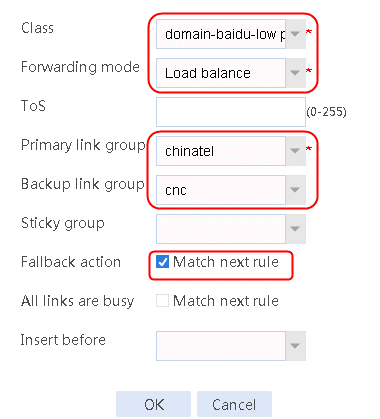
1. Navigate to the LB > Link Load Balancing > Out Link Load Balancing > Class page, and then click Create. Specify the class name as domain-baidu-low peak period and the match type as Match all. Create match rule 1, and set the match ID to 1, the type to IPv4 ACL, and the HTTP entity to 3002. Create match rule 2, and set the match ID to 2, the type to Domain name, and the HTTP entity to www.baidu.com.
Figure 73 Creating class domain-baidu-low peak period
2. Click OK.
Figure 74 Class information
3. Click OK.
4. Create classes domain-baidu-rush hour, domain-qq.com-low peak period, and domain-qq.com-rush hour in the same way class domain-baidu-low peak period is created.
Configuring an IPv4 routing policy
1. Navigate to the LB > Link Load Balancing > Out Link Load Balancing > IPv4 Routing Policy page, and then click Create.
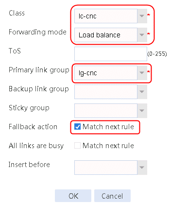
2. Create IPv4 routing policy 1, select domain-baidu-low peak period for the class, Load Balancing for the forwarding mode, chinatel for the primary link group, and select Match next rule for the fallback action.
Figure 75 Configuring IPv4 routing policy 1
3. Click OK.
4. Create other IPv4 routing policies in the same way IPv4 routing policy 1 is created.
Creating a NAT address group and applying it on the link outgoing interface
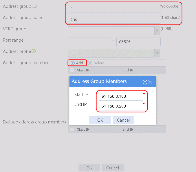
1. Navigate to the Object > Object Group > NAT Address Group page, and then click Create. Specify the address group number as 1 and the address group name as cnc-1. Click Add and set the start and end IP addresses of the new address group members to 61.156.0.100 and 61.156.0.200, respectively.
Figure 76 Configuring address group 1

2. Click OK.
Figure 77 Address group 1 information

3. Click OK.
4. Create address groups 2, 3, and 4 in the same way address group 1 is created.
5. Navigate to the Network > NAT > IPv4 > Dynamic NAT page, and then click Create to create a dynamic NAT policy. Select outgoing interface RAGG1.100 that corresponds to the link next hop address, and select NAT address group 1 for source address after NAT.
Figure 78 Creating dynamic NAT policy 1

6. Click OK.
7. Create dynamic NAT policy 2 and dynamic NAT policy 3 in the same way dynamic NAT policy 1 is created.
Verifying the configuration
1. Use the client to send HTTP packets to www.baidu.com and mail.qq.com, with the DNS server address set to 8.8.8.8.
2. View DNS cache information.
[Sysname]display loadbalance dns-cache
Slot 1
Domain name www.baidu.com
VPN instance --
Aging time 60 min
IPv4 addresses 62.180.0.10
62.180.0.11
62.180.0.12
62.180.0.21
62.180.0.22
62.180.0.31
62.180.0.32
62.180.0.41
62.180.0.42
62.180.0.51
62.180.0.52
62.180.0.61
62.180.0.62
Domain name mail.qq.com
VPN instance --
Aging time 46 min
IPv4 addresses 2.4.1.10
2.4.1.11
2.4.1.21
2.4.1.31
2.4.1.41
2.4.1.61
2.4.1.71
2.4.1.81
2.4.1.91
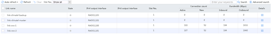
3. View the link statistics during the rush hour to verify that links link-cnc-1 and link-cnc-2 have statistics.
Figure 79 Link statistics during rush hour
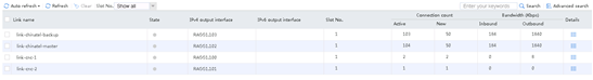
4. View the link statistics during the low peak period to verify that links link-chinatel-master and link-chinatel-backup have statistics.
Figure 80 Link statistics during low peak period
Configuration files
#
nqa template icmp icmp-cnc
next-hop ip 61.156.0.2
out interface Route-Aggregation1.100
#
nqa template icmp icmp-cmcc
next-hop ip 180.223.0.2
out interface Route-Aggregation1.101
#
nqa template icmp icmp-chinatel
next-hop ip 1.1.0.2
out interface Route-Aggregation1.102
#
nqa template icmp icmp-chinatel
next-hop ip 203.0.24.2
out interface Route-Aggregation1.103
#
loadbalance link-group cnc
transparent enable
success-criteria at-least 1
link link-cnc-1
success-criteria at-least 1
probe icmp-cnc-1
link link-cnc-2
success-criteria at-least 1
probe icmp-cnc-2
#
loadbalance link-group chinatel
transparent enable
success-criteria at-least 1
link link-chinatel-backup
success-criteria at-least 1
probe icmp-chinatel-backup
link link-chinatel-master
success-criteria at-least 1
probe icmp-chinatel-master
#
loadbalance link link-cnc-1
router ip 61.156.0.2
#
loadbalance link link-cnc-2
router ip 180.223.0.2
#
loadbalance link link-chinatel-master
router ip 1.1.0.2
#
loadbalance link link-chinatel-backup
router ip 203.0.24.2
#
time-range "low peak period" 00:00 to 07:59 working-day
time-range "low peak period" 12:01 to 13:59 working-day
time-range "low peak period" 18:01 to 24:00 working-day
time-range "low peak period" 00:00 to 24:00 off-day
time-range "rush hour" 08:00 to 12:00 working-day
time-range "rush hour" 14:00 to 18:00 working-day
#
acl advanced 3001
rule 0 permit ip time-range "rush hour"
#
acl advanced 3002
rule 0 permit ip time-range "low peak period"
#
loadbalance class "domain-baidu.com-low peak period" type link-generic
match 1 acl 3002
match 2 destination domain-name www.baidu.com
#
loadbalance class "domain-baidu.com-rush hour" type link-generic
match 1 acl 3001
match 2 destination domain-name www.baidu.com
#
loadbalance class "domain-qq.com-low peak period" type link-generic
match 1 acl 3002
match 2 destination domain-name mail.qq.com
#
loadbalance class "domain-qq.com-rush hour" type link-generic
match 1 acl 3001
match 2 destination domain-name mail.qq.com
#
loadbalance action "ob$action$#for#domain-baidu.com-low peak period" type link-generic
link-group chinatel backup cnc
fallback-action continue
#
loadbalance action "ob$action$#for#domain-baidu.com-rush hour" type link-generic
link-group cnc backup chinatel
fallback-action continue
#
loadbalance action "ob$action$#for#domain-qq.com-low peak period" type link-generic
link-group chinatel backup cnc
fallback-action continue
#
loadbalance action "ob$action$#for#domain-qq.com-rush hour" type link-generic
link-group cnc backup chinatel
fallback-action continue
#
loadbalance policy ##defaultpolicyforllbipv4##%%autocreatedbyweb%% type link-generic
class "domain-baidu.com-rush hour" action "ob$action$#for#domain-baidu.com-rush
hour"
class "domain-qq.com-rush hour" action "ob$action$#for#domain-qq.com-rush hour"
class "domain-baidu.com-low peak period" action "ob$action$#for#domain-baidu.co
m-low peak period"
class "domain-qq.com-low peak period" action "ob$action$#for#domain-qq.com-low
peak period"
default-class action ##defaultactionforllbipv4##%%autocreatedbyweb%%
#
virtual-server ##defaultvsforllbipv4##%%autocreatedbyweb%% type link-ip
virtual ip address 0.0.0.0 0
lb-policy ##defaultpolicyforllbipv4##%%autocreatedbyweb%%
service enable
#
nat address-group 1 name cnc-1
address 61.0.156.100 61.0.156.200
#
nat address-group 2 name cnc-2
address 180.223.0.100 180.223.0.200
#
nat address-group 3 name chinatel-master
address 1.1.0.100 1.1.0.200
#
nat address-group 4 name chinatel-backup
address 203.0.24.100 203.0.24.200
#
interface Route-Aggregation1.100
port link-mode route
ip address 61.0.156.1 255.255.255.0
nat outbound address-group 1
#
interface Route-Aggregation1.101
port link-mode route
ip address 180.223.0.1 255.255.255.0
nat outbound address-group 2
#
interface Route-Aggregation1.102
port link-mode route
ip address 1.1.0.1 255.255.255.0
nat outbound address-group 3
#
interface Route-Aggregation1.103
port link-mode route
ip address 203.0.24.1 255.255.255.0
nat outbound address-group 4
#
Example: Configuring proximity-based link load balancing
Network configuration
As shown in the Figure 81, the two ISPs provide four links. Configure proximity-based link load balancing for the LB device to select the optimal link to a destination and to select a link based on the scheduling algorithm if no proximity information for a destination is available. The LB device then performs proximity detection to generate proximity entries for forwarding subsequent traffic.
Figure 81 Network diagram
Analysis
For proximity-based link load balancing, complete the following tasks:
· Configuring ICMP-type health monitoring templates.
· Enable the proximity feature for the created link groups.
· Configure NAT to protect the internal network.
· Configure an ICMP-type health monitoring template for each link, specify the next hop address as that for the link and the outgoing interface in the health monitoring template, and associate this health monitoring template for the link.
Software version used
This configuration example was created and verified on Alpha 1160P16 of L1000-AK325.
Restrictions and guidelines
When you configure proximity-based load balancing, follow these restrictions and guidelines:
· The health monitory template must be referred to for the proximity function. Currently, the probe type supported by the proximity function is ICMP.
· Proximity probe is initiated for all physical links with the same destination IP address, resulting in a link group ranked by priority, and the match goes through the proximity links to find the best corresponding link belonging to the link group.
· The probe will be performed on existing proximity entries periodically before aging.
· The destination probe address is the original probe address. The current best link is obtained through the proximity algorithm. The order of the priority bi-directional link table in the corresponding dynamic proximity entry is updated, to ensure that the priority bi-directional link table of the mounted links in the proximity entry is always arranged according to the priority of each link. The period of the proximity probe is set by the user configuration.
· The optimal one of the proximity priority links is not necessarily the final pick. The current link status and whether the link is in the target link group should be considered.
· The most important thing for dynamic link load balancing is to compare which of the current links is the nearest to the destination IP address or has the smallest latency; this is the proximity probe.
· If you create the link in the link group view, the proximity cost of the link cannot be directly configured. You need to navigate to the Policy > Public Configuration > Links page to edit the link and configure the proximity link cost.
Procedure
Assigning IP addresses to interfaces
Details not shown.
Creating a health monitoring template of the ICMP type
1. Navigate to the LB > Global Configuration > Health Monitoring page, and then click Create.
Figure 82 Configuring health monitoring template icmp-cnc-1 of the ICMP type
2. Click OK.
Figure 83 Configuring health monitoring template icmp-cnc-2 of the ICMP type

3. Click OK.
Figure 84 Configuring health monitoring template icmp-chinatel-master of the ICMP type

4. Click OK.
Figure 85 Configuring health monitoring template icmp-chinatel-backup of the ICMP type

5. Click OK.
Configuring proximity
1. Navigate to the LB > Global Configuration > Proximity > Proximity Parameter page, and then click Create.
Figure 86 Configuring proximity parameters

2. Click Create default probe template to configure proximity probe template icmp of the ICMP type.
Figure 87 Configuring a proximity probe template
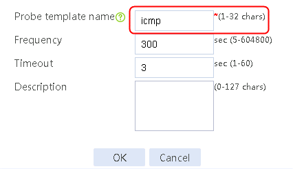
3. Click OK.
Figure 88 Configuring proximity parameters
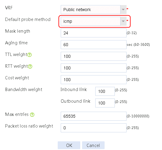
4. Click OK.
Creating link groups and enabling the proximity feature
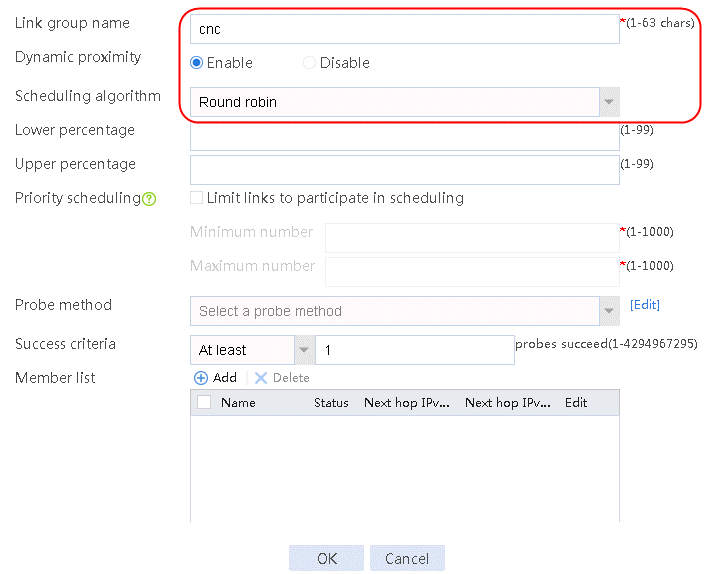
1. Navigate to the LB > Link Load Balancing > Out Link Load Balancing > Link Group page, and then click Create. Specify the link group name as cnc, enable dynamic proximity, and specify the scheduling algorithm as Round Robin.
Figure 89 Creating link group cnc
2. Click OK.
3. Create link group chinatel in the same way link group cnc is created.
Configuring links
1. Navigate to the LB > Link Load Balancing > Out Link Load Balancing > Link Group page.
2. Edit link group cnc, and click Add to create a member list. Create link link-cnc-1, configure the next hop IP address as 61.156.0.2, and the probe method as icmp-cnc-1.
Figure 90 Adding a link group member

Figure 91 Creating link link-cnc-1
3. Click OK.
4. Click Add again to create a member list. Create link link-cnc-2, configure the next hop IP address as 180.223.0.2, and the probe method as icmp-cnc-2.
Figure 92 Creating link link-cnc-2

5. Click OK.
Figure 93 Link information

6. Click OK.
7. Create links link-chinatel-master and link-chinatel-backup in the same way links link-cnc-1 and link-cnc-2 are created.
Configuring the link cost for proximity calculation
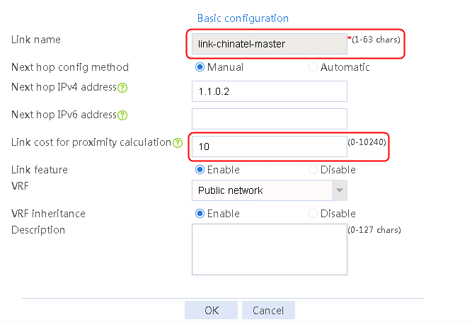
1. Navigate to the LB > Global Configuration > Links page, and then click Edit for link link-chinatel-master to configure its link cost for proximity calculation as 10.
Figure 94 Configuring the link cost for proximity calculation of link link-chinatel-master
2. Click OK.
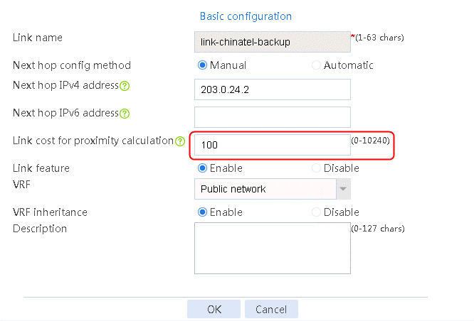
3. Click Edit for link link-chinatel-backup to configure its link cost for proximity calculation as 100.
Figure 95 Configuring the link cost for proximity calculation of link link-chinatel-backup
4. Click OK.
Enabling load balancing
1. Navigate to the LB > Link Load Balancing > Out Link Load Balancing > IPv4 Routing Policy page, and then select LB service in the Global Configuration area.
Figure 96 Enabling load balancing

2. Click Apply.
Configuring a class
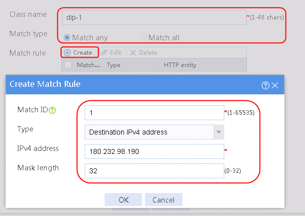
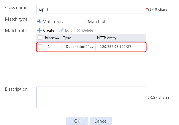
1. Navigate to the LB > Link Load Balancing > Out Link Load Balancing > Class page, and then click Create. Specify the class name as dip-1, and the match type as Match any. Create match rule 1, and set the match ID to 1, the type to Destination IPv4 address, and the HTTP entity to 183.232.98.190/32.
Figure 97 Creating class dip-1
2. Click OK.
Figure 98 Class information
3. Create class dip-2 in the same way class dip-1 is created.
Configuring an IPv4 routing policy
1. Navigate to the LB > Link Load Balancing > Out Link Load Balancing > IPv4 Routing Policy page, and then click Create.
2. Create IPv4 routing policy 1, select dip-1 for the class, Load Balancing for the forwarding mode, cnc for the primary link group, and select Match next rule for the fallback action.
Figure 99 Configuring IPv4 routing policy 1

3. Click OK.
4. Create other routing policies in the same way IPv4 routing policy 1 is created.
Creating a NAT address group and applying it at the link outgoing interface
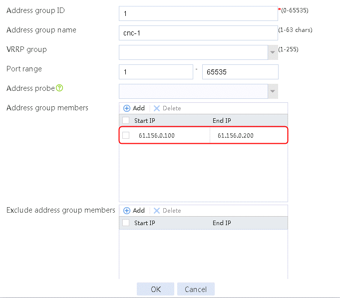
1. Navigate to the Object > Object Group > NAT Address Group page, and then click Create. Specify the address group number as 1 and the address group name as cnc-1. Click Add and set the start and end IP addresses of the new address group members to 61.156.0.100 and 61.156.0.200, respectively.
Figure 100 Configuring address group 1

2. Click OK.
Figure 101 Address group 1 information
3. Click OK.
4. Create address groups 2, 3, and 4 in the same way address group 1 is created.
5. Navigate to the Network > NAT > IPv4 > Dynamic NAT page, and then click Create to create a dynamic NAT policy. Select outgoing interface RAGG1.100 that corresponds to the link next hop address, and select NAT address group 1 for source address after NAT.
Figure 102 Creating dynamic NAT policy 1

6. Click OK.
7. Create dynamic NAT policy 2 and dynamic NAT policy 3 in the same way dynamic NAT policy 1 is created.
Verifying the configuration
1. Send HTTP traffic to the destination IP address 183.232.98.190 as an internal user.
2. Navigate to the LB > Global Configuration > Proximity > Proximity Entry page to verify that the optimal link link-cnc-1 to the destination IP address is in this proximity entry.
Figure 103 Viewing the proximity entry
![]()
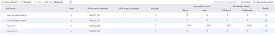
3. Navigate to the Monitor > Link Load Balancing > Links > Real-time Statistics page to view the link statistics to verify that the link-cnc-1 link has statistics.
Figure 104 Viewing link statistics
4. Shut down the outgoing interface of the link link-cnc-1.
5. View the proximity entry and the link statistics. Link link-cnc-2 has traffic statistics.
Figure 105 Viewing the proximity entry
![]()
Figure 106 Viewing link statistics
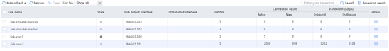
6. Send HTTP traffic to the destination IP address 61.135.169.125.
7. Navigate to the LB > Global Configuration > Proximity > Proximity Entry page to verify that the link-chinatel-master link is the optimal link to the destination IP address in this proximity entry.
Figure 107 Viewing the proximity entry
![]()
8. Navigate to the Monitor > Link Load Balancing > Links > Real-time Statistics page to view the link statistics. The link-chinatel-master link has statistics.
Figure 108 Viewing link statistics
9. Shut down the outgoing interface of the link-chinatel-master link.
10. View the proximity entry and the link statistics. The link-chinatel-backup link has statistics.
Figure 109 Viewing the proximity entry
![]()
Figure 110 Viewing link statistics
Configuration files
#
nqa template icmp icmp-cnc
next-hop ip 61.156.0.2
out interface Route-Aggregation1.100
#
nqa template icmp icmp-cmcc
next-hop ip 180.223.0.2
out interface Route-Aggregation1.101
#
nqa template icmp icmp-chinatel
next-hop ip 1.1.0.2
out interface Route-Aggregation1.102
#
nqa template icmp icmp-chinatel
next-hop ip 203.0.24.2
out interface Route-Aggregation1.103
#
loadbalance link-group cnc
proximity enable
transparent enable
success-criteria at-least 1
link link-cnc-1
success-criteria at-least 1
probe icmp-cnc-1
link link-cnc-2
success-criteria at-least 1
probe icmp-cnc-2
#
loadbalance link-group chinatel
proximity enable
transparent enable
success-criteria at-least 1
link link-chinatel-backup
success-criteria at-least 1
probe icmp-chinatel-backup
link link-chinatel-master
success-criteria at-least 1
probe icmp-chinatel-master
#
loadbalance link link-cnc-1
router ip 61.156.0.2
#
loadbalance link link-cnc-2
router ip 180.223.0.2
#
loadbalance link link-chinatel-master
router ip 1.1.0.2
cost 10
#
loadbalance link link-chinatel-backup
router ip 203.0.24.2
cost 100
#
loadbalance class dip-1 type link-generic match-any
match 1 destination ip address 183.232.98.190
#
loadbalance class dip-2 type link-generic match-any
match 1 destination ip address 61.135.169.125
#
loadbalance action ob$action$#for#dip-1 type link-generic
link-group cnc
#
loadbalance action ob$action$#for#dip-2 type link-generic
link-group chinatel
#
loadbalance policy ##defaultpolicyforllbipv4##%%autocreatedbyweb%% type link-generic
class dip-1 action ob$action$#for#dip-1
class dip-2 action ob$action$#for#dip-2
default-class action ##defaultactionforllbipv4##%%autocreatedbyweb%%
#
virtual-server ##defaultvsforllbipv4##%%autocreatedbyweb%% type link-ip
virtual ip address 0.0.0.0 0
lb-policy ##defaultpolicyforllbipv4##%%autocreatedbyweb%%
service enable
bandwidth interface statistics enable
#
nat address-group 1 name cnc-1
address 61.0.156.100 61.0.156.200
#
nat address-group 2 name cnc-2
address 180.223.0.100 180.223.0.200
#
nat address-group 3 name chinatel-master
address 1.1.0.100 1.1.0.200
#
nat address-group 4 name chinatel-backup
address 203.0.24.100 203.0.24.200
#
interface Route-Aggregation1.100
port link-mode route
ip address 61.0.156.1 255.255.255.0
nat outbound address-group 1
#
interface Route-Aggregation1.101
port link-mode route
ip address 180.223.0.1 255.255.255.0
nat outbound address-group 2
#
interface Route-Aggregation1.102
port link-mode route
ip address 1.1.0.1 255.255.255.0
nat outbound address-group 3
#
interface Route-Aggregation1.103
port link-mode route
ip address 203.0.24.1 255.255.255.0
nat outbound address-group 4
#
Example: Configuring link protection-based link load balancing
Network configuration
As shown in the Figure 111, the three ISPs provide three links. Configure link protection-based link load balancing to meet the following requirements:
· The traffic for the internal users to access the external HTTP servers is load balanced among three links. The traffic with the destination IP address matching ISP cnc and chinatel is transmitted over links link-cnc and link-chinatel, respectively, and the traffic without matching any class is transmitted over link link-cmcc.
· If traffic exceeds the bandwidth ratio of a link, the LB device distributes new traffic that does not match any sticky entries to other links.
Figure 111 Network diagram
Analysis
For link protection-based load balancing, complete the following tasks:
· Configure different bandwidths, bandwidth ratios, and bandwidth recovery ratios for links in different link groups for the LB device to determine whether a link has reached the maximum bandwidth ratio.
· Enable the link protection feature on the LB device.
· Configure an ICMP-type health monitoring template for each link, specify the next hop address as that for the link and the outgoing interface in the health monitoring template, and associate this health monitoring template for the link.
· Configure routing policies on the LB device for packets with the destination IP address matching ISPs cnc and chinatel to be sent over links link-cnc and link-chinatel, respectively, and for the packets of the default type to be sent over link link-cmcc.
· Configure the traffic with the destination IP address matching ISP cnc to be switched to link group lg-cmcc when link group lg-cnc is busy and to be switched back to link group lg-cnc when the link group is recovered.
· Configure the traffic with the destination IP address matching ISP chinatel to be switched to link group lg-cmcc when link group lg-chinatel is busy and to be switched back to link group lg-chinatel when the link group is recovered.
Software version used
This configuration example was created and verified on Alpha 1160P16 of L1000-AK325.
Restrictions and guidelines
When you configure load balancing on link protection, follow these restrictions and guidelines:
· Configure the routing policy to default. When the link group selected by the traffic with matching class is busy link group or the traffic that does not match any class, such traffic uses the link group configured in the default routing policy.
· If you create the link in the link group view, the bandwidth cost of the link cannot be directly configured. You need to navigate to the Policy > Public Configuration > Links page to edit the link and configure the bandwidth cost.
· A link group is busy when all the links in the group are busy.
Procedure
The following configurations are performed on the LB device.
If you use a physical sub-interface as the link outgoing interface, enable the sub-interface statistics function on the physical interface.
Assigning IP addresses to interfaces
Details not shown.
Importing an ISP file
1. Navigate to the LB > Global Configuration > LSP page, click Select, select an ISP file, and then click Import.
Figure 112 Importing an ISP file
Configuring a health monitoring template of the ICMP type
1. Navigate to the LB > Global Configuration > Health Monitoring page, and then click Create.
Figure 113 Creating health monitoring template icmp-cnc of the ICMP type

2. Click OK.
Figure 114 Creating health monitoring template icmp-cmcc of the ICMP type

3. Click OK.
Figure 115 Creating health monitoring template icmp-chinatel of the ICMP type
4. Click OK.
Creating link groups
1. Navigate to the LB > Link Load Balancing > Out Link Load Balancing > Link Group page, and then click Create. Specify the link group name as lg-cnc, and the scheduling algorithm as source IP address hash.
Figure 116 Creating link group lg-cnc
2. Click OK.
3. Create link groups lg-cmcc and lg-chinatel in the same way link group lg-cnc is created.
Configuring links
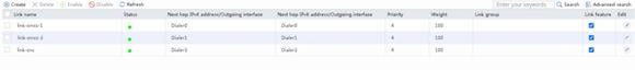
1. Navigate to the LB > Link Load Balancing > Out Link Load Balancing > Link Group page.
2. Edit link group lg-cnc and click Add to create a member list. Create link link-cnc, and configure the next hop IP address as 61.156.0.2 and the probe method as icmp-cnc.
Figure 117 Adding a link group member

Figure 118 Creating a link

3. Click OK.
Figure 119 Link information

4. Click OK.
5. Create links lg-cmcc and lg-chinatel in the same way link lg-cnc is created.
6. Navigate to the LB > Global Configuration > Links page, click Edit for link link-cnc and set its bandwidth ratio to 20%, bandwidth recovery ratio to 10% under total bandwidth, and the expected bandwidth under maximum bandwidth to 100000 Kbps.
Figure 120 Editing link link-cnc
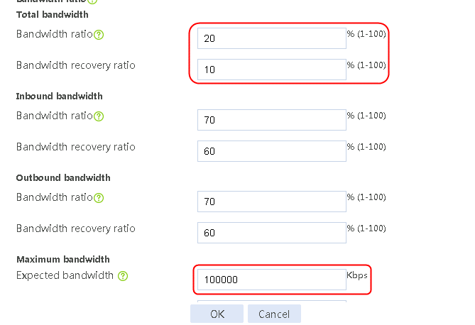
7. Click OK.
8. Edit link link-chinatel in the same way link link-cnc is edited.
Enabling load balancing
1. Navigate to the LB > Link Load Balancing > Out Link Load Balancing > IPv4 Routing Policy page, and then select LB service and Link protection in the Global Configuration area.
Figure 121 Enabling load balancing
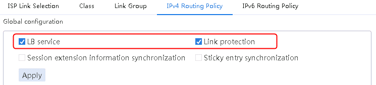
2. Click Apply.
Configuring a class
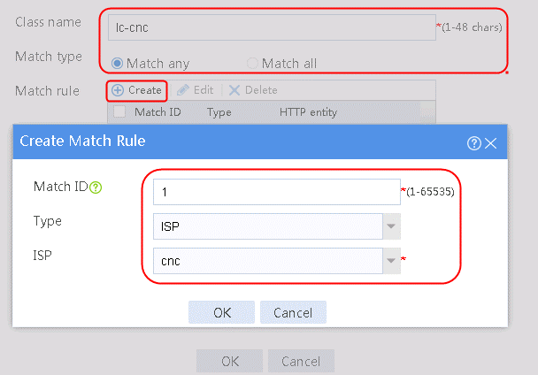
1. Navigate to the LB > Link Load Balancing > Out Link Load Balancing > Class page, and then click Create. Specify the class name as lc-cnc, and the match type as Match any. Create new match rule, and set the match ID to 1, the type to ISP, and the HTTP entity to cnc.
Figure 122 Creating a class
2. Click OK.
Figure 123 Class information

3. Click OK.
4. Create class lc-chinatel in the same way class lc-cnc is created.
Configuring an IPv4 routing policy
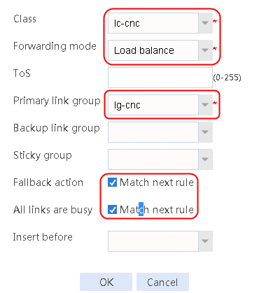
1. Navigate to the LB > Link Load Balancing > Out Link Load Balancing > IPv4 Routing Policy page, and then click Create.
2. Create IPv4 routing policy 1, select lc-cnc for the class, Load Balancing for the forwarding mode, lg-cnc for the primary link group, and select Match next rule for the fallback action and for All links are busy.
Figure 124 Configuring IPv4 routing policy 1
3. Click OK.
4. Create other IPv4 routing policies in the same way IPv4 routing policy 1 is created.
Creating a NAT address group and applying it at the link outgoing interface
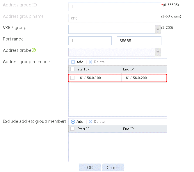
1. Navigate to the Object > Object Group > NAT Address Group page, and then click Create. Specify the address group number as 1 and the address group name as cnc. Click Add and set the start and end IP addresses of the new address group members to 61.156.0.100 and 61.156.0.200, respectively.
Figure 125 Creating address group 1

2. Click OK.
Figure 126 Address group 1 information
3. Click OK.
4. Create address groups 2 and 3 in the same way address group 1 is created.
5. Navigate to the Network > NAT > IPv4 > Dynamic NAT page, and then click Create to create a dynamic NAT policy. Select outgoing interface RAGG1.100 that corresponds to the link next hop address, and select NAT address group 1 for source address after NAT.
Figure 127 Creating dynamic NAT policy 1

6. Click OK.
7. Create dynamic NAT policy 2 and dynamic NAT policy 3 in the same way dynamic NAT policy 1 is created.
Verifying the configuration
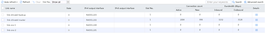
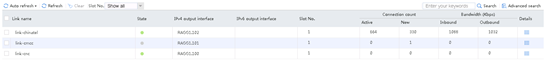
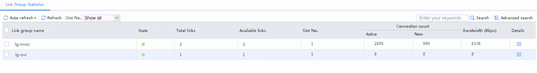
1. Use the client to send packets with the destination IP address matching ISP cnc. The traffic on link link-cnc has not reached the maximum bandwidth ratio. View the link statistics to verify that traffic is distributed to link group lg-cnc, and link group lg-cnc has statistics.
Figure 128 Statistics about link group lg-cnc
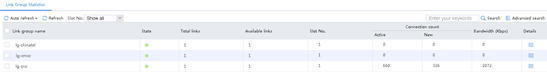
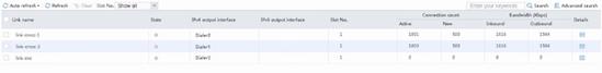
Figure 129 Statistics about link link-cnc
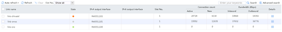
2. Send large throughput (100M) traffic as an internal user. The maximum bandwidth ratio is reached on link link-cnc. View the link statistics to verify that traffic is distributed to link group lg-cmcc, and links link-cnc and link-cmcc have statistics.
Figure 130 Statistics about link groups with large throughput
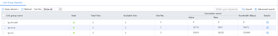
Figure 131 Statistics about links with large throughput
3. View the link status. Link link-cnc is busy.
Figure 132 Viewing the link status
![]()
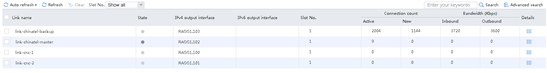
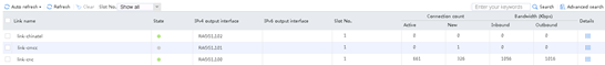
4. Use the client to send packets with the destination IP address matching ISP chinatel. The traffic on link link-chinatel has not reached the maximum bandwidth ratio. View the link statistics to verify that traffic is distributed to link group lg-chinatel, and link group lg-cnc has statistics.
Figure 133 Statistics about link group lg-chinatel
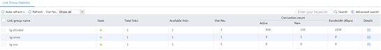
Figure 134 Statistics about link link-chinatel
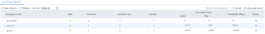
5. Send large throughput (100M) traffic as an internal user. The maximum bandwidth ratio is reached on link link-chinatel. View the link statistics to verify that traffic is distributed to link group lg-chinatel, and links link-chinatel and link-cmcc have statistics.
Figure 135 Statistics about link groups with large throughput
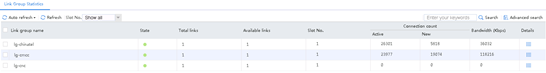
Figure 136 Statistics about links with large throughput
6. View the link status. Link link-chinatel is busy.
Figure 137 Viewing the link status

Configuration files
#
loadbalance isp file lbispinfo-v1.7.tp
#
nqa template icmp icmp-cnc
next-hop ip 61.156.0.2
out interface Route-Aggregation1.100
#
nqa template icmp icmp-cmcc
next-hop ip 211.98.0.2
out interface Route-Aggregation1.101
#
nqa template icmp icmp-chinatel
next-hop ip 203.0.24.2
out interface Route-Aggregation1.102
#
loadbalance link-group lg-cnc
predictor hash address source
transparent enable
success-criteria at-least 1
link link-cnc
success-criteria at-least 1
probe icmp-cnc
#
loadbalance link-group lg-chinatel
predictor hash address source
transparent enable
success-criteria at-least 1
link link-chinatel
success-criteria at-least 1
probe icmp-chinatel
#
loadbalance link-group lg-cmcc
transparent enable
link link-chinatel
success-criteria at-least 1
probe icmp-chinatel
link link-cmcc
success-criteria at-least 1
probe icmp-cmcc
link link-cnc
success-criteria at-least 1
probe icmp-cnc
#
loadbalance link link-cnc
router ip 61.156.0.2
max-bandwidth 100000 kbps
bandwidth busy-rate 20 recovery 10
#
loadbalance link link-cmcc
router ip 211.98.0.2
#
loadbalance link link-chinatel
router ip 203.0.24.2
max-bandwidth 100000 kbps
bandwidth busy-rate 20 recovery 10
#
loadbalance class lc-cnc type link-generic match-any
match 1 isp cnc
#
loadbalance class lc-chinatel type link-generic match-any
match 1 isp chinatel
#
loadbalance action ##defaultactionforllbipv4##%%autocreatedbyweb%% type link-gen
eric
link-group lg-cmcc
#
loadbalance action ob$action$#for#lc-cnc type link-generic
link-group lg-cnc
fallback-action continue
busy-action continue
#
loadbalance action ob$action$#for#lc-chinatel type link-generic
link-group lg-chinatel
fallback-action continue
busy-action continue
#
loadbalance policy ##defaultpolicyforllbipv4##%%autocreatedbyweb%% type link-gen
eric
class lc-cnc action ob$action$#for#lc-cnc
class lc-chinatel action ob$action$#for#lc-chinatel
default-class action ##defaultactionforllbipv4##%%autocreatedbyweb%%
#
virtual-server ##defaultvsforllbipv4##%%autocreatedbyweb%% type link-ip
virtual ip address 0.0.0.0 0
lb-policy ##defaultpolicyforllbipv4##%%autocreatedbyweb%%
service enable
bandwidth busy-protection enable
bandwidth interface statistics enable
#
nat address-group 1
address 61.156.0.100 61.156.0.200
#
nat address-group 2
address 211.98.0.100 211.98.0.200
#
nat address-group 3
address 203.0.24.100 203.0.24.200
#
interface Route-Aggregation1.100
port link-mode route
ip address 61.156.0.1 255.255.255.0
nat outbound address-group 1
#
interface Route-Aggregation1.101
port link-mode route
ip address 211.98.0.1 255.255.255.0
nat outbound address-group 2
#
interface Route-Aggregation1.102
port link-mode route
ip address 203.0.24.1 255.255.255.0
nat outbound address-group 3
#
Example: Configuring PPPoE-based link load balancing
Network configuration
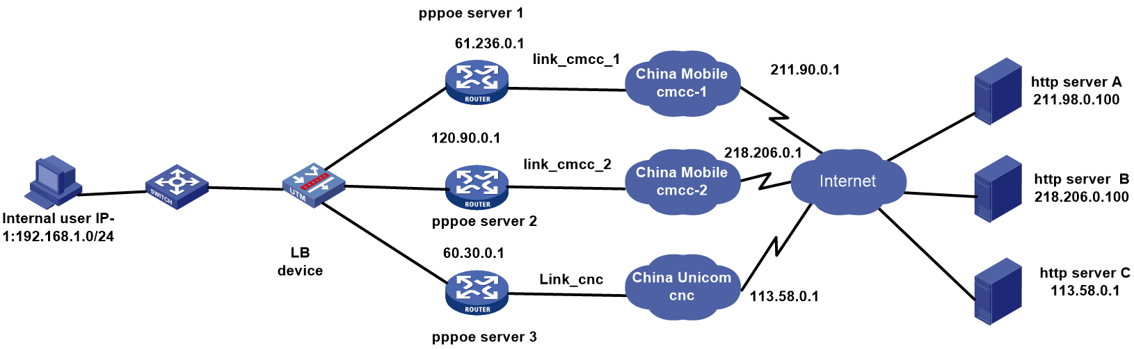
As shown in the Figure 138, the three ISPs provide three links. Configure PPPoE-based link load balancing for the traffic with the destination IP address matching ISPs China Mobile cmcc or China Unicom cnc to be distributed to the corresponding links in link groups lg-cmcc and lg-cnc.
Figure 138 Network diagram
Analysis
For PPPoE-based link load balancing, complete the following tasks:
· Configure PPPoE client settings on the outgoing interface of the LB device for automatic address acquisition from PPPoE servers.
· For health monitoring, specify the destination IP address and outgoing interface.
· Configure dialer interfaces Dialer 0, Dialer 1, and Dialer 2 for the LB device, configure the operating modes, and bind the dialer interfaces to the link outgoing interfaces.
· Configure a user on the PPPoE server with the service type PPP, and configure a password for the user.
· Configure an IP address pool and a VT interface on the PPPoE server. Configure the PAP or CHAP authentication method for the VT interface, and use an IP address in the IP address pool as the remote IP address, and bind the VT interface to the outgoing interface.
· Configure links link-cmcc-1, link-cmcc-2, and link-cnc, and assign links link-cmcc-1 and link-cmcc-2 to link group lg-cmcc and link link-cnc to link group lg-cnc.
· Configure classes to meet the following requirements:
¡ Traffic with the destination address matching China Mobile ISP entries is transmitted over either of the two China Mobile links, whichever is optimal.
¡ Traffic with the destination address matching China Unicom ISP entries and traffic that does not match any entries are transmitted over China Unicom links.
· Apply a NAT address group to the outgoing interface of the LB device to protect the internal network.
Software version used
This configuration example was created and verified on Alpha 1160P16 of L1000-AK325.
Restrictions and guidelines
When you configure PPPoE-based link load balancing, follow these restrictions and guidelines:
· The username and password configured on the PPPoE server must be the same as those configured on the Dialer interfaces of the LB device.
· The PPPoE client must operate in permanent mode.
· Before you configure the PPPoE client, configure a Dialer interface and enable bundle DDR on the Dialer interface. Each PPPoE session corresponds to a dialer bundle, and each dialer bundle corresponds to a dialer interface.
· Import the most recent ISP file:
a. Access the H3C website at http://www.h3c.com/.
b. Navigate to the Support > Resource Center > Software Download > Security > Load Balancing > Comware V7 series > H3C ISP File page to download the file. After download, this file can be imported. Alternatively, you can upload an ISP file, and import the file by executing the loadbalance isp file command at the CLI to import the file to the device.
Procedure
Assigning IP addresses to interfaces
Details not shown.
Importing an ISP file
1. Navigate to the LB > Global Configuration > LSP page, click Select, select an ISP file, and then click Import.
Figure 139 Importing an ISP file

2. Click Import.
Configuring a health monitoring template of the ICMP type
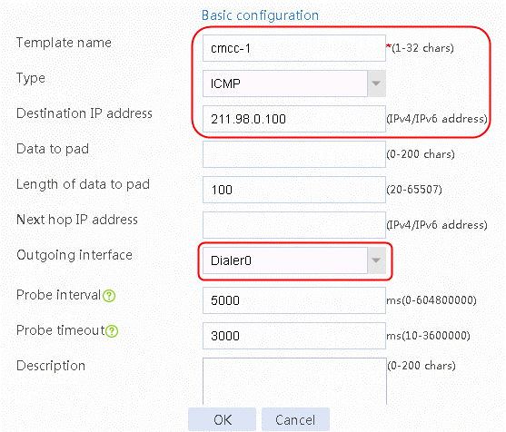
1. Navigate to the LB > Global Configuration > Health Monitoring page, and then click Create.
Figure 140 Creating health monitoring template cmcc-1 of the ICMP type
2. Click OK.
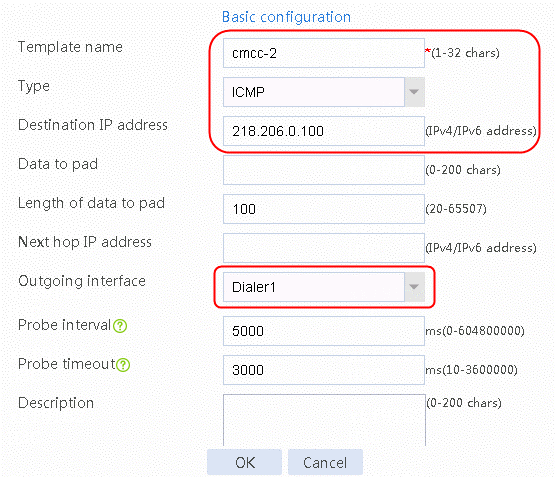
Figure 141 Creating health monitoring template cmcc-2 of the ICMP type
3. Click OK.
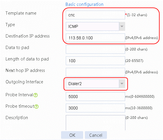
Figure 142 Creating health monitoring template cnc of the ICMP type
4. Click OK.
Creating a link group
1. Navigate to the LB > Link Load Balancing > Out Link Load Balancing > Link Group page, and then click Create. Specify the link group name as lg-cmcc, and the scheduling algorithm as source IP address hash.
Figure 143 Creating link group lg-cmcc
2. Click OK.
3. Create link group lg-cnc in the same way link group lg-cmcc is created.
Configuring links
1. Navigate to the LB > Link Load Balancing > Out Link Load Balancing > Link Group page.
2. Edit link group lg-cmcc and click Add to create a member list. Create link link-cmcc-1, configure the next hop configuration method as Automatic, the outgoing interface as Dialer0, and the probe method as cmcc-1.
Figure 144 Adding a link group member
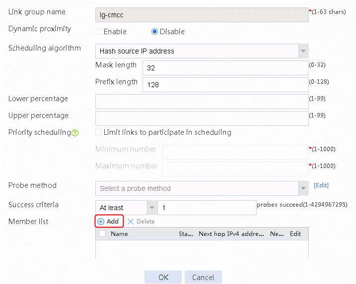
Figure 145 Creating link link-cmcc -1
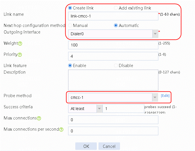
3. Click OK.
4. Click Add on the member list again to create a member list. Create link link-cmcc-2, configure the next hop configuration method as Automatic, the outgoing interface as Dialer1, and the probe method as cmcc-2.
Figure 146 Creating link link-cmcc -2

5. Click OK.
Figure 147 Link information

6. Click OK.
7. Create link link-cnc in the same way links link-cmcc-1 and link-cmcc-2 are created.
Configuring a class
1. Navigate to the LB > Link Load Balancing > Out Link Load Balancing > Class page, and then click Create. Specify the class name as lc-cnc, and the match type as Match any. Create new match rule, and set the match ID to 1, the type to ISP, and the HTTP entity to cnc.
Figure 148 Creating a class

2. Click OK.
Figure 149 Class information
3. Click OK.
4. Create class lc-cmcc in the same class lc-cnc is created.
Enabling load balancing
1. Navigate to the LB > Link Load Balancing > Out Link Load Balancing > IPv4 Routing Policy page, and then select LB service in the Global Configuration area.
Figure 150 Enabling load balancing

2. Click Apply.
Configuring an IPv4 routing policy
1. Navigate to the LB > Link Load Balancing > Out Link Load Balancing > IPv4 Routing Policy page, and then click Create.
2. Create IPv4 routing policy 1, select lc-cnc for the class, Load Balancing for the forwarding mode, lg-cnc for the primary link group, and select Match next rule for the fallback action.
Figure 151 Creating IPv4 routing policy 1

3. Click OK.
4. Create other IPv4 routing policies in the same way IPv4 routing policy 1 is created.
Creating a NAT address group and applying it at the link outgoing interface
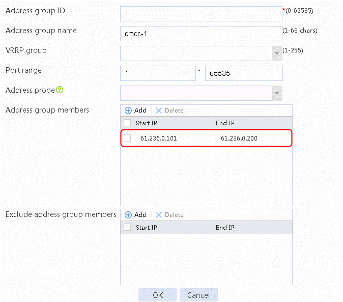
1. Navigate to the Object > Object Group > NAT Address Group page, and then click Create. Specify the address group number as 1 and the address group name as cnc. Click Add and set the start and end IP addresses of the new address group members to 61.156.0.100 and 61.156.0.200, respectively.
Figure 152 Creating address group 1

2. Click OK.
Figure 153 Address group 1 information
3. Click OK.
4. Create address groups 2 and 3 in the same way address group 1 is created.
5. Navigate to the Network > NAT > IPv4 > Dynamic NAT page, and then click Create to create a dynamic NAT policy. Select Dia0 for interface, and select NAT address group 1 for source address after NAT.
Figure 154 Creating a dynamic NAT policy
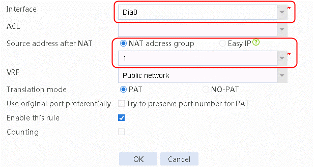
6. Click OK.
7. Create dynamic NAT policy 2 and dynamic NAT policy 3 in the same way dynamic NAT policy 1 is created.
Verifying the configuration
Figure 155 IP address obtained dynamically from PPPoE server
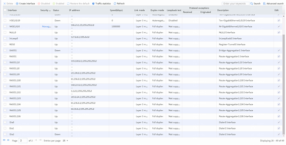
Figure 156 Viewing the link health monitoring status (Active)
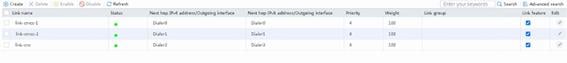
Figure 157 Viewing the link group status
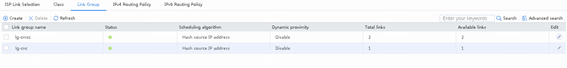
Figure 158 Viewing the link status
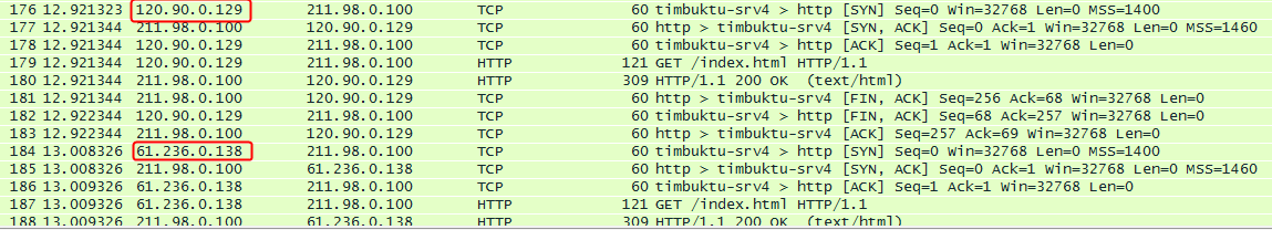
1. Use the client to access the China Mobile HTTP server at 211.98.0.100 to verify that traffic is distributed to the China Mobile link group lg-cmcc.
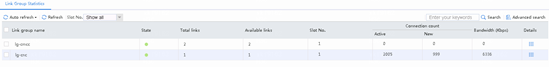
Figure 159 Statistics about China Mobile link group lg-cmcc
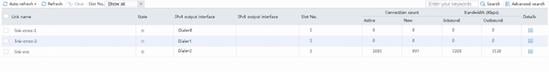
2. Verify that China Mobile link groups lg-cmcc-1 and link-cmcc-2 have statistics.
3. Catch packets at the server end to verify that traffic is distributed to the China Mobile links:
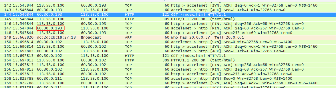
4. Use the client to access the China Unicom HTTP server at 113.58.0.100 to verify that traffic is distributed to the China Unicom link group lg-cnc.
Figure 160 Statistics about China Unicom link group lg-cnc
5. Verify that China Unicom link link-cnc has statistics.
6. Catch packets at the server end to verify that traffic is distributed to the China Unicom links:
Configuration files
PPPoE server 1 configuration, the interface IP addresses, and routing are omitted.
#
ip pool cmcc-1 61.236.0.2 61.236.0.100
#
interface Virtual-Template1
ppp authentication-mode pap
remote address pool cmcc-1
ip address 61.236.0.1 255.254.0.0
#
interface GigabitEthernet0/2
port link-mode route
pppoe-server bind virtual-template 1
#
local-user cmcc-1 class network
password cipher $c$3$1ZIo7GlPtTv1UHwNMIzc8Dhg1GmFVaHcJA==
service-type ppp
authorization-attribute user-role network-operator
#
PPPoE server 2 configuration, the interface IP addresses, and routing are omitted.
#
ip pool cmcc-2 120.90.0.2 120.90.0.100
#
interface Virtual-Template2
ppp authentication-mode pap
remote address pool cmcc-2
ip address 120.90.0.1 255.254.0.0
#
interface GigabitEthernet0/3
port link-mode route
combo enable copper
pppoe-server bind virtual-template 2
#
local-user cmcc-2 class network
password cipher $c$3$Rm+edPrA3lE7DBWtbl8PApfG03zzD5D9Ow==
service-type ppp
authorization-attribute user-role network-operator
#
PPPoE server 3 configuration, the interface IP addresses, and routing are omitted.
#
ip pool cnc 60.30.0.2 60.30.0.100
#
interface Virtual-Template3
ppp authentication-mode pap
remote address pool cnc
ip address 60.30.0.1 255.255.0.0
#
interface GigabitEthernet1/0/4
port link-mode route
pppoe-server bind virtual-template 3
#
local-user cnc class network
password cipher $c$3$JxugKxQzmNdeU+VUnKYMXL+s8VjNhYi5FA==
service-type ppp
authorization-attribute user-role network-operator
#
LB configuration, the interface IP addresses, and routing are omitted.
#
dialer-group 1 rule ip permit
dialer-group 2 rule ip permit
dialer-group 3 rule ip permit
#
nat address-group 1 name cmcc-1
address 61.236.0.101 61.236.0.200
#
nat address-group 2 name cmcc-2
address 120.90.0.101 120.90.0.200
#
nat address-group 3 name cnc
address 60.30.0.101 60.30.0.200
#
#
nqa template icmp cmcc-1
destination ip 211.98.0.100
out interface Dialer0
#
nqa template icmp cmcc-2
destination ip 218.206.0.100
out interface Dialer1
#
nqa template icmp cnc
destination ip 113.58.0.100
out interface Dialer2
#
#
interface Reth1
ip address 192.168.1.1 255.255.255.0
member interface GigabitEthernet1/0/1 priority 255
member interface GigabitEthernet2/0/2 priority 100
#
interface Reth2
member interface GigabitEthernet1/0/3 priority 255
member interface GigabitEthernet2/0/6 priority 100
pppoe-client dial-bundle-number 0
#
interface Reth3
member interface GigabitEthernet1/0/4 priority 255
member interface GigabitEthernet2/0/7 priority 100
pppoe-client dial-bundle-number 1
#
interface Reth4
member interface GigabitEthernet1/0/5 priority 255
member interface GigabitEthernet2/0/8 priority 100
pppoe-client dial-bundle-number 2
#
interface Dialer0
mtu 1492
ppp chap password cipher $c$3$/rUoTVdCcUfL0DRYEQhOr/YbELbiNcnFJQ==
ppp chap user cmcc-1
ppp ipcp dns admit-any
ppp ipcp dns request
ppp pap local-user cmcc-1 password cipher $c$3$J8EDIZqQwH3eOS2LcW32Q5X0yRG/mlC25A==
dialer bundle enable
dialer-group 3
dialer timer idle 0
dialer timer autodial 5
ip address ppp-negotiate
tcp mss 1400
nat outbound address-group 1
#
interface Dialer1
mtu 1492
ppp chap password cipher $c$3$IoX2VokNU8+s+K0FIy/Ad0dhw8MRQrU0Bg==
ppp chap user cmcc-2
ppp ipcp dns admit-any
ppp ipcp dns request
ppp pap local-user cmcc-2 password cipher $c$3$xiNpK8gRYfScZYbI0uGomm8i+Q0og1q/bA==
dialer bundle enable
dialer-group 2
dialer timer idle 0
dialer timer autodial 5
ip address ppp-negotiate
tcp mss 1400
nat outbound address-group 2
#
interface Dialer2
mtu 1492
ppp chap password cipher $c$3$7/6RKGeYLyVZkwb+LC/NOOw24aPLnQE9vw==
ppp chap user cnc
ppp ipcp dns admit-any
ppp ipcp dns request
ppp pap local-user cnc password cipher $c$3$J5vSqazlXWRGeW1lkuCgg6JRaXOLHJKW2w==
dialer bundle enable
dialer-group 1
dialer timer idle 0
dialer timer autodial 5
ip address ppp-negotiate
tcp mss 1400
nat outbound address-group 3
#
loadbalance link-group lg-cmcc
predictor hash address source
transparent enable
success-criteria at-least 1
link link-cmcc-1
success-criteria at-least 1
link link-cmcc-2
success-criteria at-least 1
#
loadbalance link-group lg-cnc
predictor hash address source
transparent enable
success-criteria at-least 1
link link-cnc
success-criteria at-least 1
#
loadbalance class lc-cmcc type link-generic
match 1 isp cmcc
#
loadbalance class lc-cnc type link-generic
match 1 isp cnc
#
loadbalance action ##defaultactionforllbipv4##%%autocreatedbyweb%% type link-generic
link-group lg-cnc
#
loadbalance action ob$action$#for#lc-cmcc type link-generic
link-group lg-cmcc
fallback-action continue
#
loadbalance action ob$action$#for#lc-cnc type link-generic
link-group lg-cnc
fallback-action continue
#
loadbalance policy ##defaultpolicyforllbipv4##%%autocreatedbyweb%% type link-generic
class lc-cmcc action ob$action$#for#lc-cmcc
class lc-cnc action ob$action$#for#lc-cnc
default-class action ##defaultactionforllbipv4##%%autocreatedbyweb%%
#
virtual-server ##defaultvsforllbipv4##%%autocreatedbyweb%% type link-ip
virtual ip address 0.0.0.0 0
lb-policy ##defaultpolicyforllbipv4##%%autocreatedbyweb%%
bandwidth interface statistics enable
service enable
#
loadbalance isp file flash:/lbispinfo.tp
#
loadbalance link link-cmcc-1
router interface Dialer0
success-criteria at-least 1
probe cmcc-1
#
loadbalance link link-cmcc-2
router interface Dialer1
success-criteria at-least 1
probe cmcc-2
#
loadbalance link link-cnc
router interface Dialer2
success-criteria at-least 1
probe cnc
#
return
Example: Configuring intelligent link selection based on packet loss ratio
Network configuration
As shown in the Figure 161, the two ISPs provide two links. Set a packet loss ratio weight in the proximity parameters, and specify a link quality algorithm for the link groups for the system select the optimal link for the traffic to access the external HTTP server based on the packet loss ratio.
Figure 161 Network diagram
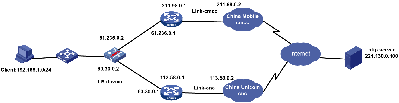
Analysis
For intelligent link selection based on packet loss ratio, complete the following tasks:
· Configure a packet loss ratio weight in proximity parameters.
· Configure a link quality algorithm for the link groups.
· To avoid influences from other factors on the link quality, set the TTL weight, RTT weight, cost weight, and bandwidth weight to 0.
· Use WAN emulation on the link to simulate the packet loss ratio.
· Configure an ICMP-type health monitoring template for each link, and specify the next hop IP address for the link in the health monitoring template.
· Apply a NAT address group to the outgoing interface of the LB device to protect the internal network.
Software version used
This configuration example was created and verified on Alpha 1160P16 of L1000-AK325.
Restrictions and guidelines
When you configure intelligent link selection based on packet loss ratio, follow these restrictions and guidelines:
· In the same link group view, the proximity enable command and the link quality algorithm configuration are mutually exclusive. When one command is configured, the other one is removed automatically.
· Packet loss ratio calculation is applicable only to link load balancing.
· For links link-cmcc and link-cnc to be assigned to the same link group, create link group lg.
· Create the IPv4 routing policy as the default policy, and select Load Balancing for the forwarding mode and lg for the primary link group.
Procedure
Assigning IP addresses to interfaces
Details not shown.
Creating a health monitoring template of the ICMP type
1. Navigate to the LB > Global Configuration > Health Monitoring page, and then click Create.
Figure 162 Creating health monitoring template icmp-cmcc of the ICMP type
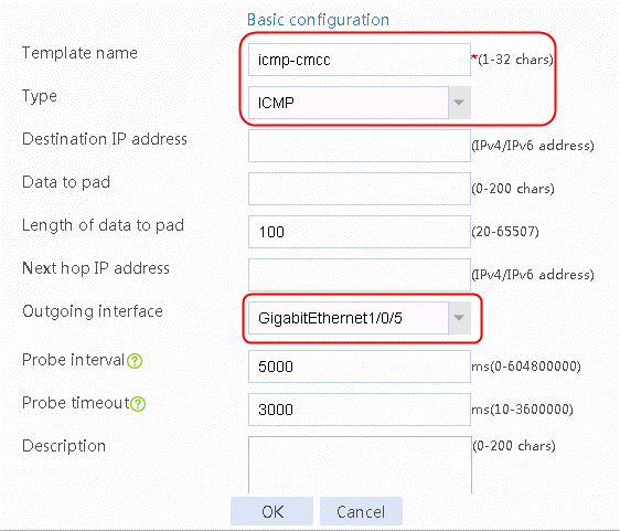
2. Click OK.
Figure 163 Creating health monitoring template icmp-cnc of the ICMP type
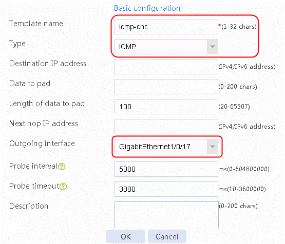
3. Click OK.
Creating a link group
1. Navigate to the LB > Link Load Balancing > Out Link Load Balancing > Link Group page, and then click Create. Specify the link group name as lg-cnc, and the scheduling algorithm as link quality algorithm.
Figure 164 Creating link group lg
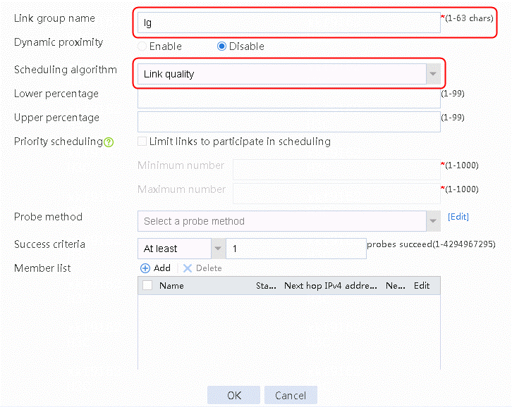
2. Click OK.
Configuring links
1. Navigate to the LB > Link Load Balancing > Out Link Load Balancing > Link Group page.
2. Edit link group lg-cnc and click Add to create a member list. Create link link-cnc, and configure the next hop IP address as 61.156.0.2 and the probe method as icmp-cnc.
3. Click Add to the right of the member list. Create link link-cmcc, and configure the next hop IPv4 address as 61.236.0.1 and the probe method as icmp-cmcc.
Figure 165 Adding a link group member
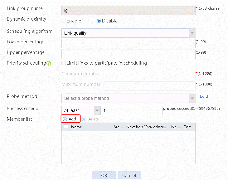
Figure 166 Creating link link-cmcc
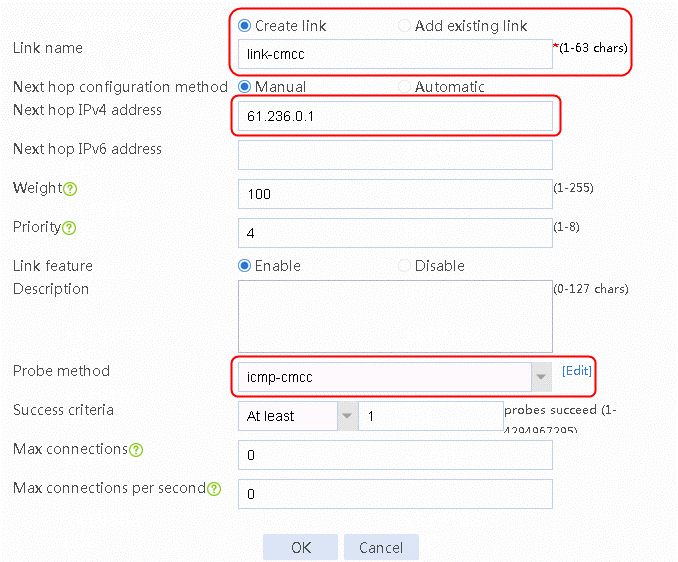
4. Click OK.
5. Click Add to the right of the member list. Create link link-cnc, configure the next hop IPv4 address as 60.30.0.1, and the probe method as icmp-cnc.
Figure 167 Creating link link-cnc

6. Click OK.
Figure 168 Link information

7. Click OK.
Configuring proximity
1. Navigate to the LB > Global Configuration > Proximity > Proximity Parameter page, and then click Create.
Figure 169 Configuring proximity parameters
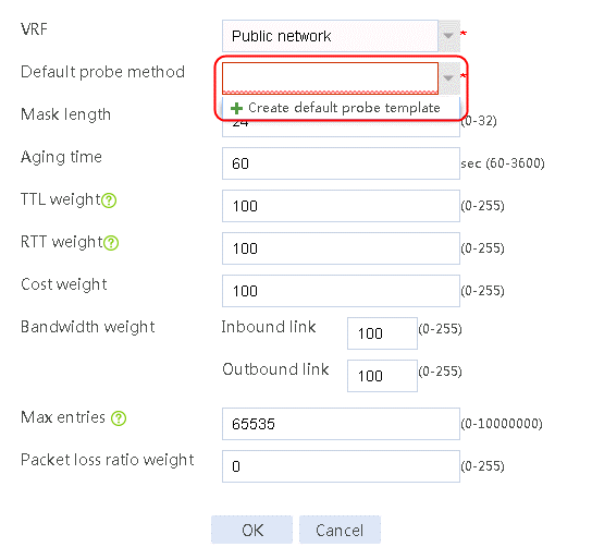
2. Click Create default probe template to configure a proximity probe template named lb-icmp of the ICMP type.
Figure 170 Configuring a proximity probe template
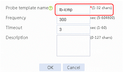
3. Click OK.
4. Navigate to the Policy > Public Configuration > Proximity > Proximity Parameters page, and then click Create. Select the default probe template lb-icmp, configure the TTL weight, RTT weight, cost weight and bandwidth weight as 0, and the packet loss ratio weight as 255.
Figure 171 Configuring proximity parameters
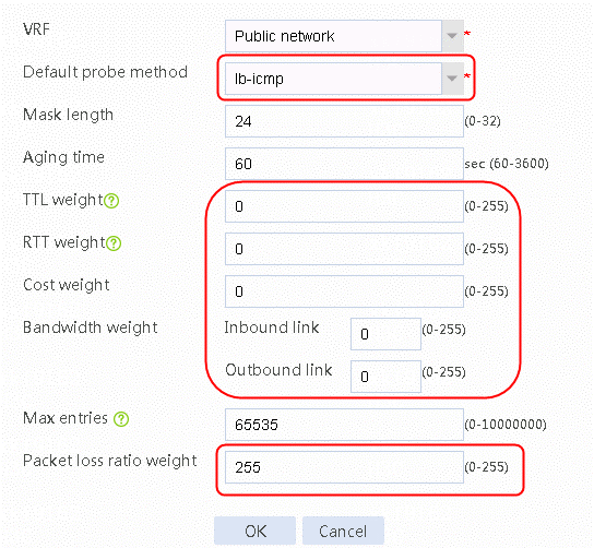
5. Click OK.
Enabling load balancing
1. Navigate to the LB > Link Load Balancing > Out Link Load Balancing > IPv4 Routing Policy page, and then select LB service in the Global Configuration area.
Figure 172 Enabling load balancing

2. Click Apply.
Configuring an IPv4 routing policy
1. Navigate to the LB > Link Load Balancing > Out Link Load Balancing > IPv4 Routing Policy page, and then click Create. Configure the default forwarding mode as Load Balance and the primary link group as lg.
Figure 173 Creating default IPv4 routing policy
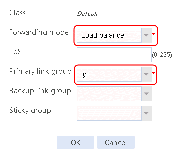
2. Click OK.
Creating a NAT address group and applying it at the link outgoing interface
1. Navigate to the Object > Object Group > NAT Address Group page, and then click Create. Specify the address group number as 1 and the address group name as cnc. Click Add and set the start and end IP addresses of the new address group members to 61.156.0.100 and 61.156.0.200, respectively.
Figure 174 Creating address group 1
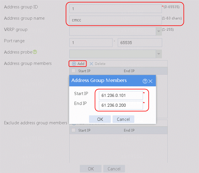
2. Click OK.
Figure 175 Address group 1 information
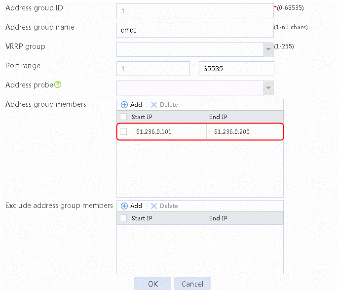
3. Create address group 2 in the same way address group 1 is created.
4. Navigate to the Network > NAT > IPv4 > Dynamic NAT page, and then click Create to create a dynamic NAT policy. Select outgoing interface RAGG1.100 that corresponds to the link next hop address, and select NAT address group 1 for source address after NAT.
Figure 176 Creating dynamic NAT policy 1
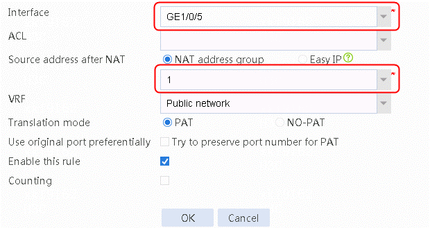
5. Click OK.
6. Navigate to the Network > NAT > IPv4 > Dynamic NAT page, and then click Create to create a dynamic NAT policy. Select outgoing interface GE 1/0/17 that corresponds to the link next hop address, and select NAT address group 2 for source address after NAT.
Verifying the configuration
1. On the WAN emulator, set the packet loss ratio to 0 for China Mobile link link-cmcc and China Unicom link link-cnc. Send HTTP traffic to access the destination IP address 221.130.0.100 as an internal user.
2. Navigate to the LB > Global Configuration > Links page. Verify that links link-cmcc and link-cnc are in normal state.
![]()
3. After the default probe period of 300s, navigate to the Monitor > Link Load Balancing > Links > Real-time Statistics page to view statistics about the links to verify that the traffic statistics about the two links are consistent.
Figure 177 Link statistics
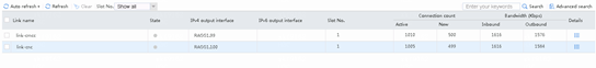
4. Navigate to the Monitor > Link Load Balancing > Links > Real-time Statistics page to view the packet loss ratio. The packet loss ratio of the two links are both 0.
Figure 178 Viewing the packet loss ratio of the China Mobile link link-cmcc
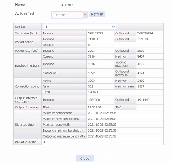
Figure 179 Viewing the packet loss ratio of the China Unicom link link-cnc

5. View the proximity entries for IP address 221.130.0.0 to verify that links link-cmcc and link-cnc have the same dynamic weights.
dis loadbalance proximity ip 221.130.0.0
(*) - Real server object
Slot 1:
IPv4 address/Mask length: 221.130.0.0/24
Timeout: 60
Link list:
Name RTT Dynamic weight
link-cmcc 2 127
link-cnc 2 127
6. Verify that link-cmcc is selected as the optimal link.
![]()
7. On the WAN emulator, set the packet loss ratio to 30% and 10%, respectively, for China Mobile link link-cmcc and China Unicom link link-cnc. Send HTTP traffic to access the destination IP address 221.130.0.100 as an internal user.
8. Navigate to the LB > Global Configuration > Links page. Verify that links link-cmcc and link-cnc are in normal state.
![]()
9. After the default probe period of 300s, navigate to the Monitor > Link Load Balancing > Links > Real-time Statistics page to view the statistics about the links. The number of connections on link link-cnc is higher than that on link link-cmcc.
Figure 180 Link statistics
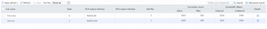
10. Navigate to the Monitor > Link Load Balancing > Links > Real-time Statistics page, and then click Details at the end of each statistics entry to view the packet loss ratio. The packet loss ratio for the China Mobile link is 28%, which is close to the value set on the WAN emulator. The packet loss ratio for the China Unicom link is 10%, which is consistent with the value set on the WAN emulator.
Figure 181 Viewing the packet loss ratio for the China Mobile link link-cmcc
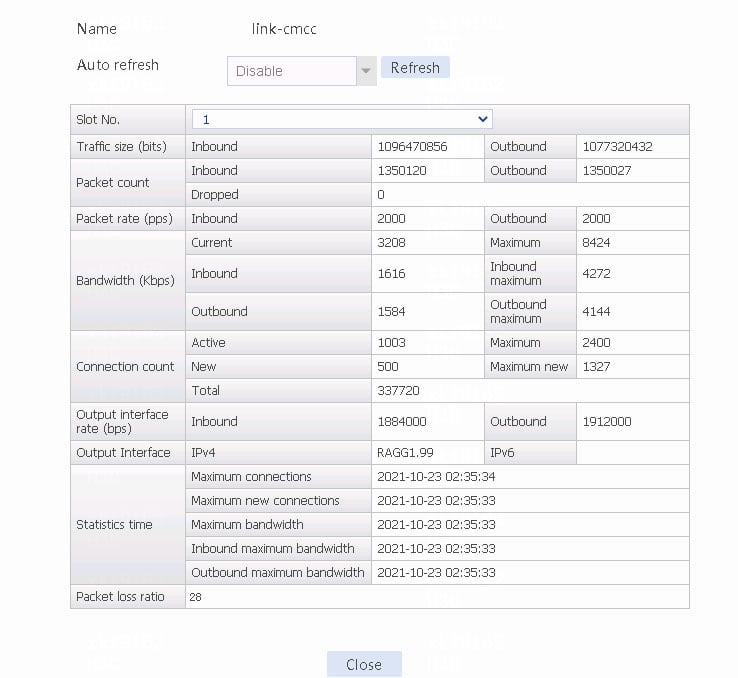
Figure 182 Viewing the packet loss ratio for the China Unicom link link-cnc
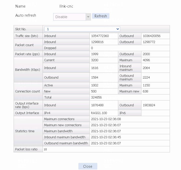
11. View the proximity entries for IP address 221.130.0.0. Link link-cnc has higher dynamic weight than that of link link-cnc.
dis loadbalance proximity ip 221.130.0.0
(*) - Real server object
Slot 1:
IPv4 address/Mask length: 221.130.0.0/24
Timeout: 60
Link list:
Name RTT Dynamic weight
link-cnc 0 140
link-cmcc 0 114
12. Verify that the China Unicom link link-cnc is selected as the optimal link.
![]()
Configuration files
#
nat address-group 1 name cmcc
address 61.236.0.101 61.236.0.200
#
nat address-group 2 name cnc
address 60.30.0.101 60.30.0.200
#
nqa template icmp icmp-cmcc
destination ip 211.98.0.2
#
nqa template icmp icmp-cnc
destination ip 113.58.0.2
#
interface GigabitEthernet1/0/5
port link-mode route
ip address 61.236.0.2 255.254.0.0
nat outbound address-group 1
#
interface GigabitEthernet 1/0/17
port link-mode route
ip address 60.30.0.2 255.255.0.0
nat outbound address-group 2
#
loadbalance link-group lg
predictor link-quality
transparent enable
success-criteria at-least 1
link link-cmcc
success-criteria at-least 1
link link-cnc
success-criteria at-least 1
#
loadbalance action ##defaultactionforllbipv4##%%autocreatedbyweb%% type link-generic
link-group lg
#
loadbalance policy ##defaultpolicyforllbipv4##%%autocreatedbyweb%% type link-generic
default-class action ##defaultactionforllbipv4##%%autocreatedbyweb%%
#
virtual-server ##defaultvsforllbipv4##%%autocreatedbyweb%% type link-ip
virtual ip address 0.0.0.0 0
lb-policy ##defaultpolicyforllbipv4##%%autocreatedbyweb%%
bandwidth interface statistics enable
service enable
#
loadbalance proximity
bandwidth inbound weight 0
bandwidth outbound weight 0
cost weight 0
rtt weight 0
ttl weight 0
packet-loss-rate weight 255
match default lb-probe lb-icmp
#
loadbalance link link-cmcc
router ip 61.236.0.1
success-criteria at-least 1
probe icmp-cmcc
#
loadbalance link link-cnc
router ip 60.30.0.1
success-criteria at-least 1
probe icmp-cnc
#
loadbalance probe-template icmp lb-icmp
#
Example: Configuring ISP auto update-based link load balancing
Network configuration
As shown in Figure 183, the two ISPs provide two links. Configure ISP auto update-based link load balancing for the LB device to communicate with the WHOIS server in real time to obtain dynamic information about the ISP.
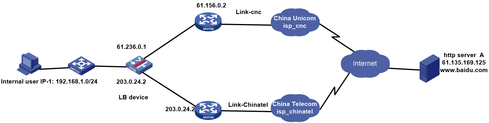
Analysis
For ISP auto update-based link load balancing, complete the following tasks:
· Enable the ISP auto update feature.
· Configure the domain name or IPv4 address of the WHOIS server.
· Select the ISP update frequency.
· Configure the WHOIS sign for the current ISP.
Software version used
This configuration example was created and verified on Alpha 1160P16 of L1000-AK325.
Restrictions and guidelines
When you configure ISP auto update-based load balancing, follow these restrictions and guidelines:
· Use the Python script to simulate the WHOIS server on a lab PC with an IP address of 61.135.169.125 because the WHOIS server is on the public network.
· The ISP auto update frequency can be Per-day, Per-week or Per-month. The specific update time for ISP is at around 4:02:00 one day/week/month after the last update.
Procedure
Assigning IP addresses to interfaces
Details not shown.
Enabling the ISP auto update feature
1. Navigate to the LB > Global Configuration > Health Monitoring page, and then click Auto Update.
Figure 184 Enabling the ISP auto update feature
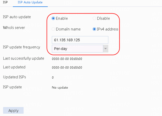
2. Click Apply.
Configuring a WHOIS server sign
1. Navigate to the Policy > Public Configuration > ISP page, and then click the ISP address segment tab. Click Create in the ISP list area to create an ISP entry named isp-chinatel and specify the WHOIS sign as chinatel.
Figure 185 Creating an ISP entry
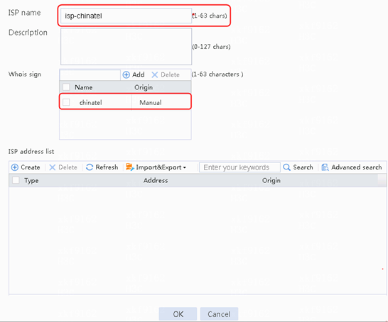
2. Click OK.
3. Run the prepared Python script that simulates the WHOIS server on a PC.
Figure 186 Running the Python script that simulates the WHOIS server
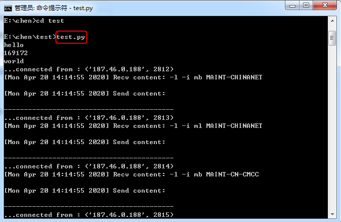
Setting the date and time
1. Navigate to the System > Maintenance > Settings > Date and Time page, and then select Manually set the date and time as the configuration method.
Figure 187 Setting the date and time
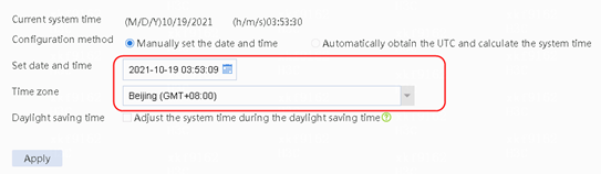
2. Click Apply.
Verifying the configuration
1. Manually set the date to 2021-10-25 and time to 04:02:34. Wait until the set date and time is reached and verify that ISP update is successful.
Figure 188 Last updated time and update result
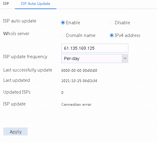
2. Verify that the update details are listed in the ISP IP address list:
Figure 189 Details in the ISP IP address list
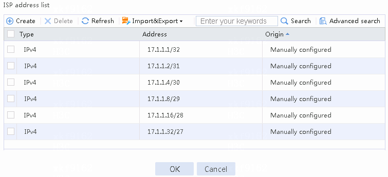
Configuration files
#
loadbalance isp name isp-chinatel
whois-mntner chinatel
#
loadbalance isp auto-update enable
loadbalance isp auto-update frequency per-day
loadbalance isp auto-update whois-server ip 61.135.169.125
#
Transparent DNS proxy configuration examples
Overview
Transparent DNS proxy can load balance the traffic of internal users that access the external DNS servers among multiple links.
Network configuration
As shown in the Figure 190, the two ISPs provide two public IP addresses. Configure transparent DNS proxy to meet the following requirements:
· DNS servers at 183.232.98.190 and 183.232.98.191 resolve the DNS requests to mail.qq.com.
· DNS servers at 61.135.169.125 and 61.135.169.126 resolve the DNS requests to www.baidu.com, with the one that has a higher priority as the primary, and the other as the backup.
Figure 190 Network diagram
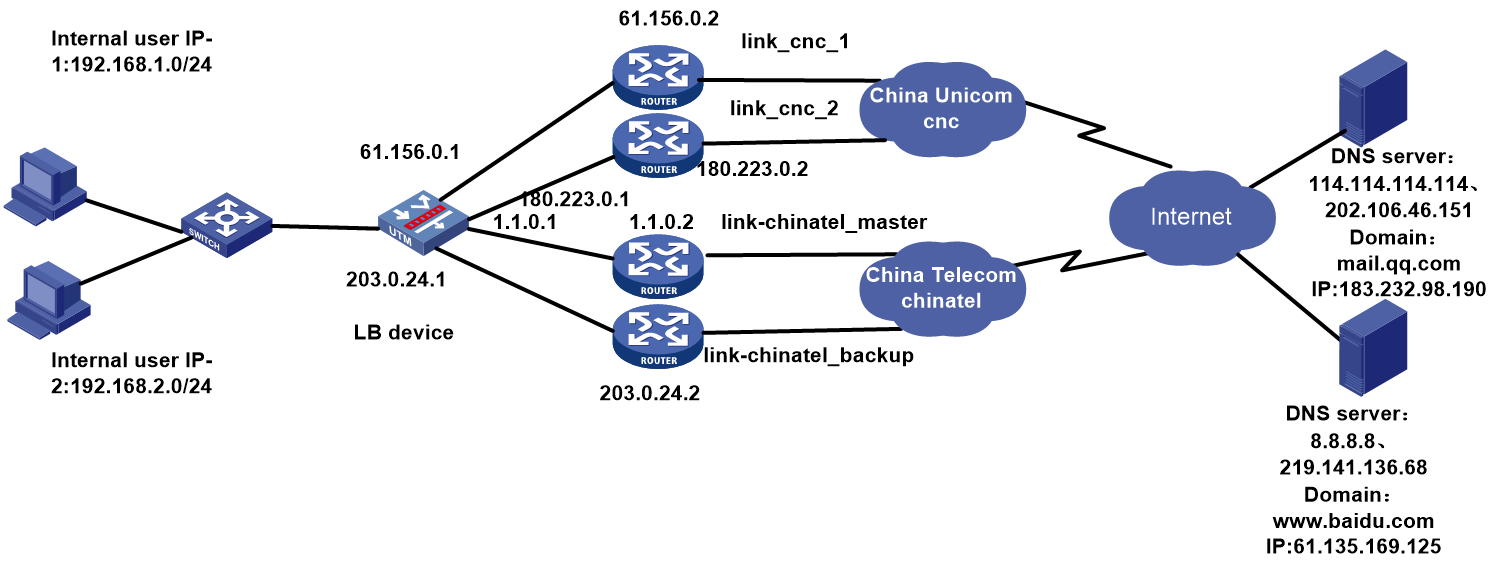
Analysis
For transparent DNS proxy-based link load balancing, complete the following tasks:
· Configure NAT to protect the internal network.
· Configure the transparent DNS proxy on the LB device and reference to the policies.
· Reference the ICMP-type health monitoring template and specify the next hop IP address for each link.
· Reference the DNS-type health monitoring template on the DNS server, and configure the destination IP address and domain name to be parsed in the DNS-type health monitoring template.
Software version used
This configuration example was created and verified on Alpha 1160P16 of L1000-AK315.
Restrictions and guidelines
When you configure the transparent DNS proxy, follow these restrictions and guidelines:
· Configure the default DNS servers. A record parsing is taken as an example.
· Make sure the DNS server IP address set at the client cannot be an IP address on the device or an IP address in the same network segment and make sure the DNS request packets from the client can be sent to the LB device.
· If outbound link load balancing is also configured, make sure you configure the link settings for transparent DNS proxy are the same as those for outbound link load balancing.
Procedure
Creating health monitoring templates of the ICMP and DNS types
1. Navigate to the LB > Global Configuration > Health Monitoring page, and then click Create. Create ICMP-type health monitoring templates icmp-cnc-1, icmp-cnc-2, icmp-chinatel-master, and icmp-chinatel-backup, and configure the next hop IP addresses 61.156.0.2, 180.223.0.2, 1.1.0.2, and 203.0.24.2, respectively.
Figure 191 Creating health monitoring template icmp-cnc-1 of the ICMP type
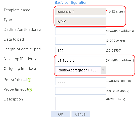
2. Click OK.
Figure 192 Creating health monitoring template icmp-cnc-2 of the ICMP type
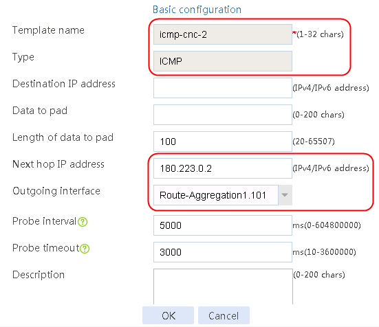
3. Click OK.
Figure 193 Creating health monitoring template icmp-chinatel-master of the ICMP type
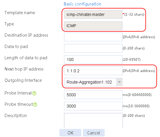
4. Click OK.
Figure 194 Creating health monitoring template icmp-chinatel-backup of the ICMP type
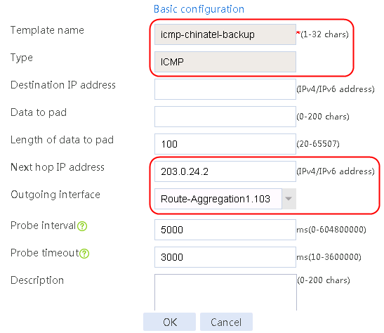
5. Click OK.
6. Navigate to the LB > Global Configuration > Health Monitoring page, and then click Create. Create DNS-type health monitoring templates dns114.114.114.114, dns202.106.46.151, dns219.141.136.68, and dns8.8.8.8, configure their destination IP addresses and domain names, and configure the TTL value as 255.
Figure 195 Creating health monitoring template dns114.114.114.114 of the DNS type
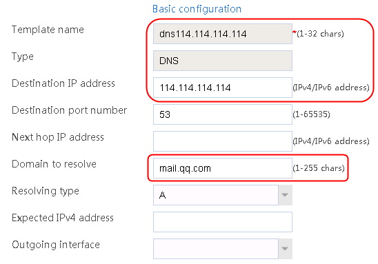
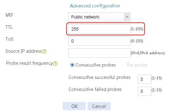
7. Click OK.
Figure 196 Creating health monitoring template dns202.106.46.151 of the DNS type
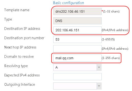
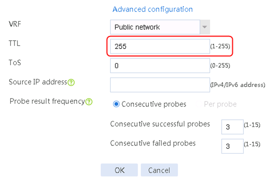
8. Click OK.
Figure 197 Creating health monitoring template dns219.141.136.68 of the DNS type

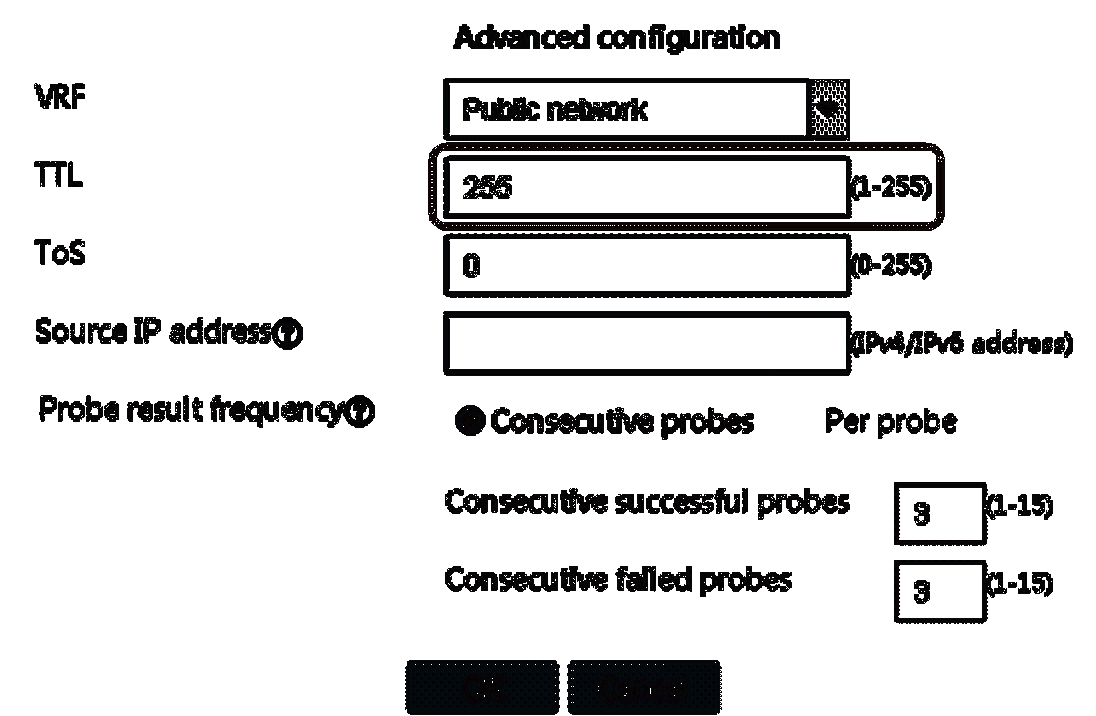
9. Click OK.
Figure 198 Creating health monitoring template dns8.8.8.8 of the DNS type
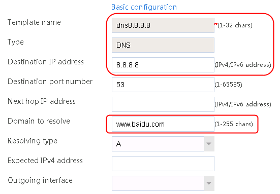
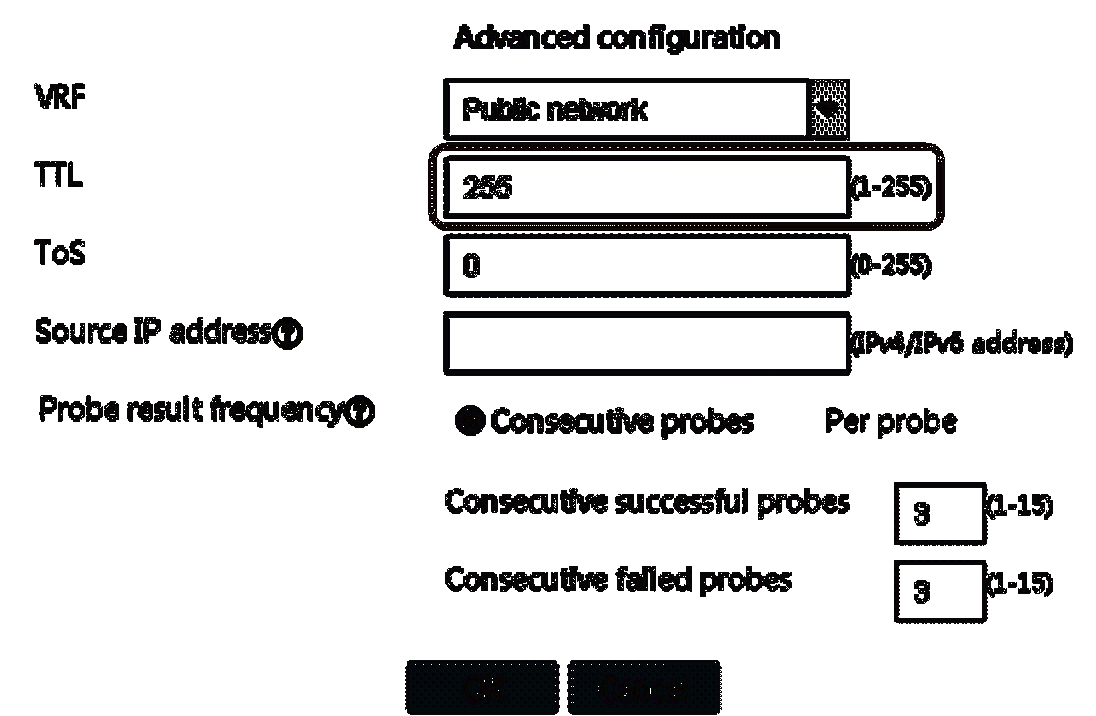
10. Click OK.
Creating a DNS server pool
1. Navigate to the LB > Link Load Balancing > DNS Proxy > DNS Server Pool page, and then click Create. Create DNS server pools dsp-qq and dsp-baidu, and configure the scheduling algorithm as Round robin:
Figure 199 Creating DNS server dsp-qq
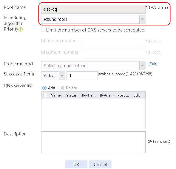
2. Click OK.
3. Create DNS server pool dsp-baidu in the same way DNS server pool dsp-qq is created.
Figure 200 DNS server pool information
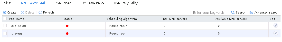
Creating a DNS server
1. Navigate to the LB > Link Load Balancing > DNS Proxy > DNS Server Pool page.
2. Edit DNS server pool dsp-qq and create a member list. The names of the new server farms are dns-qq-1 and dns-qq-2. Edit DNS server pool dsp-baidu and create a member list. The names of the new server farms are dns-baidu-master and dns-baidu-backup.
Figure 201 Adding a member to DNS server pool dsp-qq
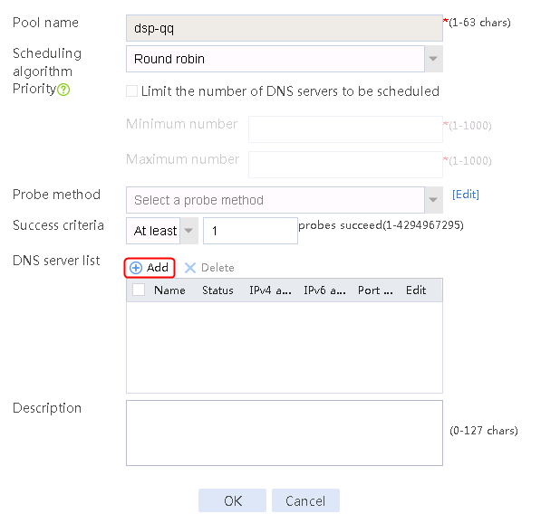
Figure 202 Creating DNS server dsp-qq-1
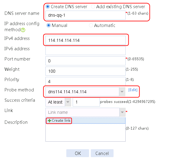
3. Click Create link to create link link-cnc-1, configure the next hop IP address as 61.156.0.2 and the probe method as icmp-cnc-1.
Figure 203 Creating link link-cnc-1
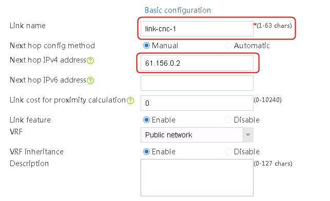
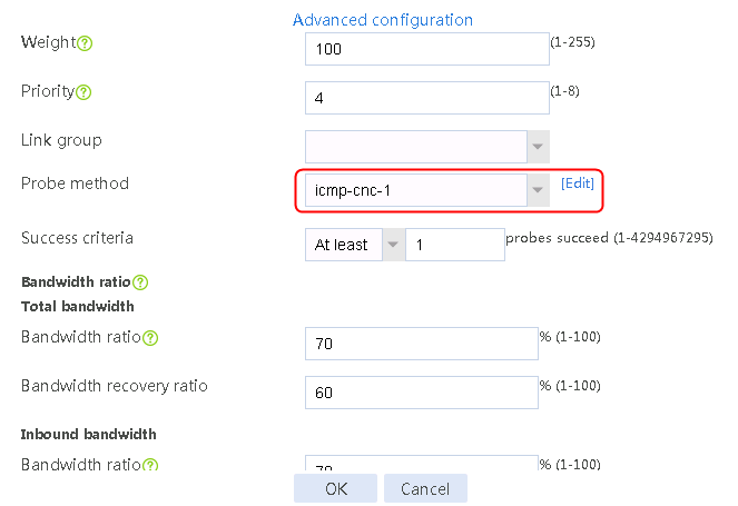
4. Click OK.
Figure 204 Creating DNS server dsp-qq-2
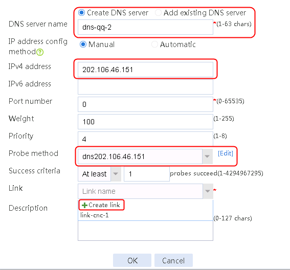
5. Click Create link to create link link-cnc-2, configure the next hop IP address as 61.156.0.2 and the probe method as icmp-cnc-2.
Figure 205 Creating link link-cnc-2
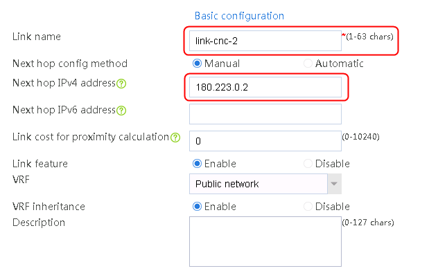

6. Click OK.
Figure 206 DNS server information
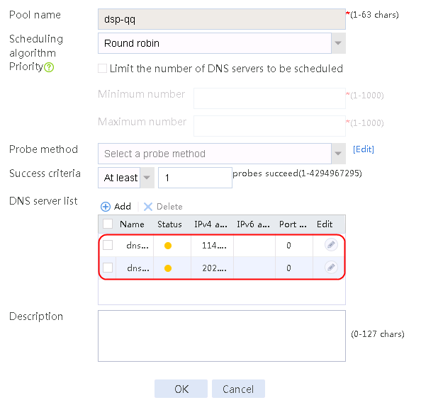
7. Navigate to the LB > Link Load Balancing > DNS Proxy > DNS Server Pool page.
8. Edit DNS server pool dsp-baidu and create a member list. The names of the new server farms are dns-baidu-master and dns-baidu-backup, respectively.
Figure 207 Adding a member to DNS server pool dsp-qq
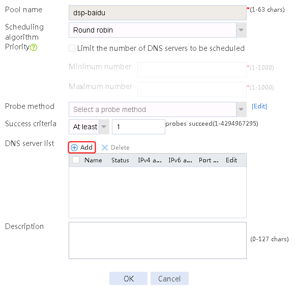
Figure 208 Creating DNS server dsp-baidu-master
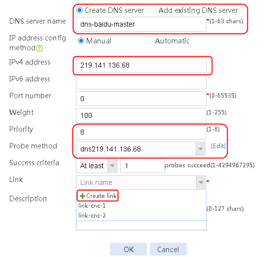
9. Click Create link to create link link-chinatel-master, configure the next hop IP address as 1.1.0.2 and the probe method as icmp-chinatel-master.
Figure 209 Creating link link-chinatel-master
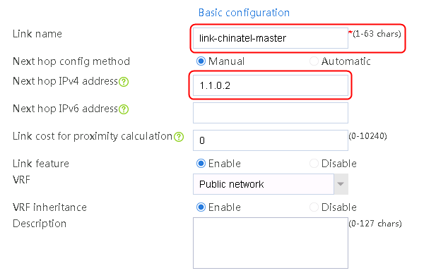
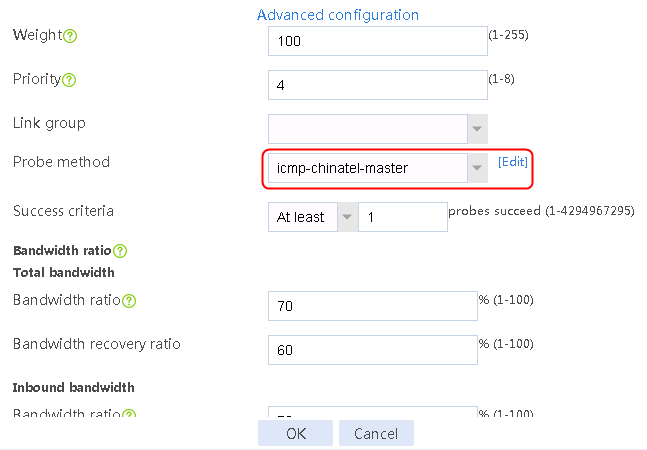
10. Click OK.
Figure 210 Creating DNS server dsp-baidu-backup
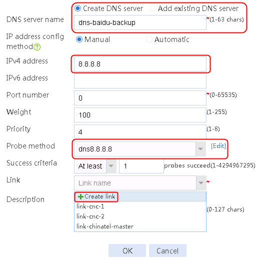
11. Click Create link to create link link-chinatel-backup, configure the next hop IP address as 203.0.24.2 and the probe method as icmp-chinatel-backup.
Figure 211 Creating link link-chinatel-backup
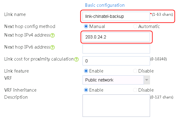

12. Click OK.
Figure 212 DNS server information
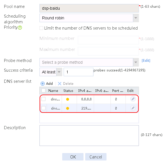
Creating a class
1. Navigate to the LB > Link Load Balancing > DNS Proxy > Class page, and then click Create.
2. Create class domain-qq.com to match domain name mail.qq.com.
Figure 213 Creating class domain-qq.com
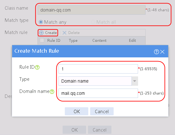
3. Click OK.
Figure 214 Class information
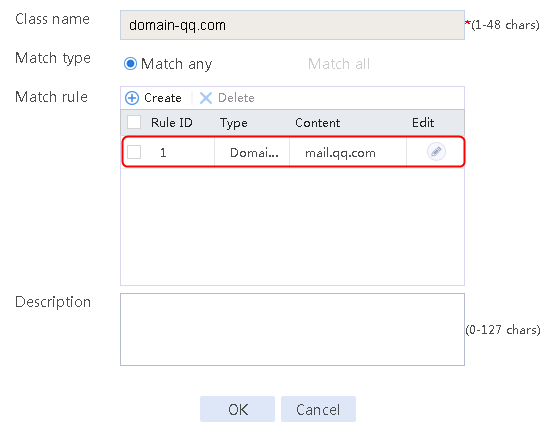
4. Create class domain-baidu.com to match domain name www.qq.com.
Figure 215 Creating class domain-baidu.com
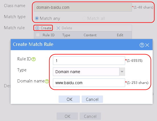
5. Click OK.
Figure 216 Class information
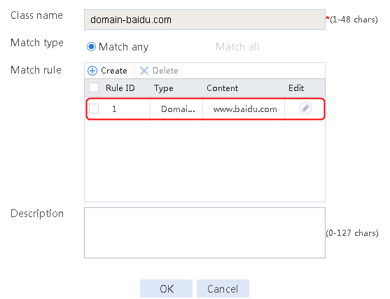
Enabling transparent DNS Proxy
1. Navigate to the LB > Link Load Balancing > DNS Proxy > IPv4 Proxy Policy page, and then enable Transparent DNS proxy in the common configuration.
Figure 217 Network diagram
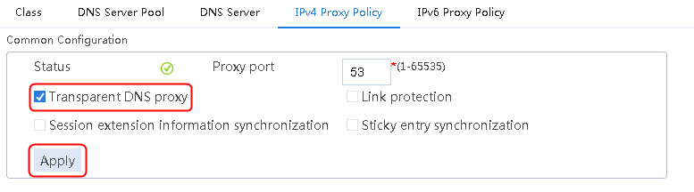
2. Click Apply.
Creating an IPv4 routing policy
1. Navigate to the LB > Link Load Balancing > DNS Proxy > IPv4 Proxy Policy page, and then click Create. Create a new policy and configure dsp-qq as the default DNS server pool.
Figure 218 Creating IPv4 proxy policy-1
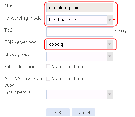
2. Click OK.
Figure 219 Creating IPv4 proxy policy-2
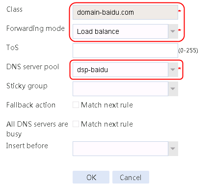
3. Click OK.
Figure 220 Configuring the default action
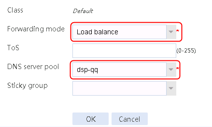
4. Click OK.
Creating a NAT address group and applying it at the link outgoing interface
1. Navigate to the Object > Object Group > NAT Address Groups page, and then click Create to create address group 1.
Figure 221 Creating address group 1
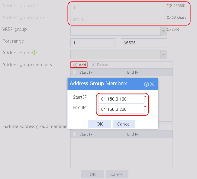
2. Click OK.
Figure 222 Address group 1 information
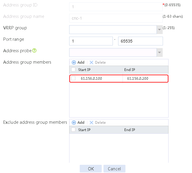
3. Create address groups 2, 3, and 4 in the same way address group 1 is created.
Figure 223 Address group 2 information

Figure 224 Address group 3 information
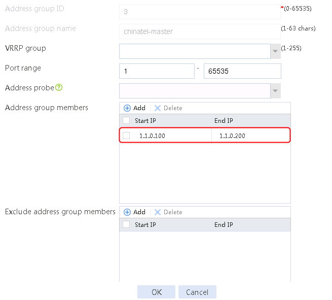
Figure 225 Address group 4 information
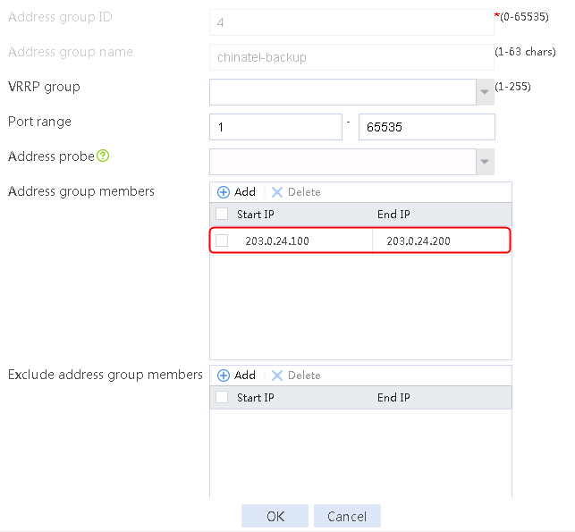
4. Navigate to the Network > NAT > Dynamic NAT page, and then click Create to create a dynamic NAT policy.
Figure 226 Creating dynamic NAT policy 1
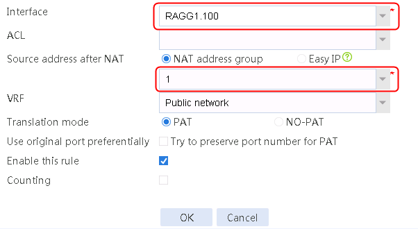
5. Click OK.
Figure 227 Creating dynamic NAT policy 2
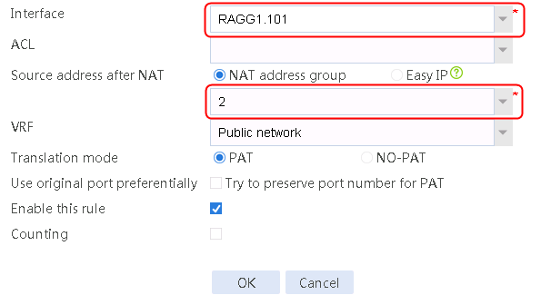
6. Click OK.
Figure 228 Creating dynamic NAT policy 3
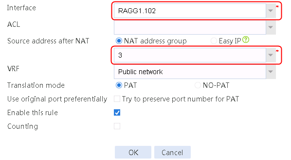
7. Click OK.
Figure 229 Creating dynamic NAT policy 4
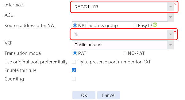
8. Click OK.
Verifying the configuration
1. Use the client to send a DNS request to www.baidu.com.
2. Viewing the DNS server status.
Figure 230 DNS server status
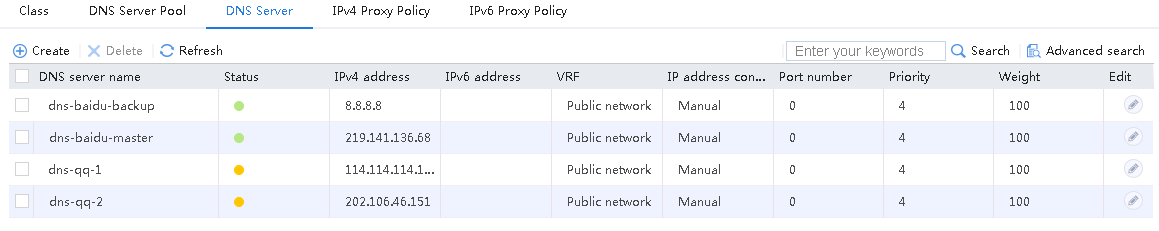
3. Navigate to the Monitor > Link Load Balancing > DNS Proxy Statistics > DNS Servers page.
4. View the DNS server statistics to verify that DNS server dns-baidu-master has traffic statistics, and DNS server dns-baidu-backup does not have traffic statistics, because the DNS request is sent to DNS server dns-baidu-master with a higher priority.
Figure 231 DNS server statistics
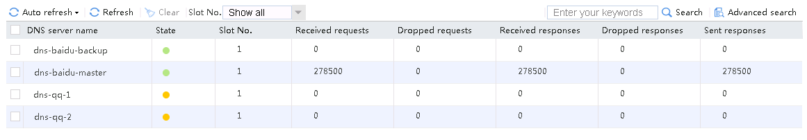
5. Shut down the outgoing interface for link link-chinatel-master.
6. Viewing the link status.
Figure 232 Link status after link link-chinatel-master is shut down
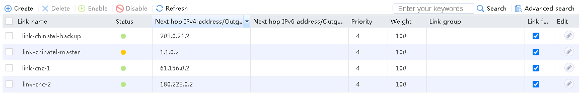
7. View the DNS server status.
Figure 233 DNS server status after link link-chinatel-master is shut down
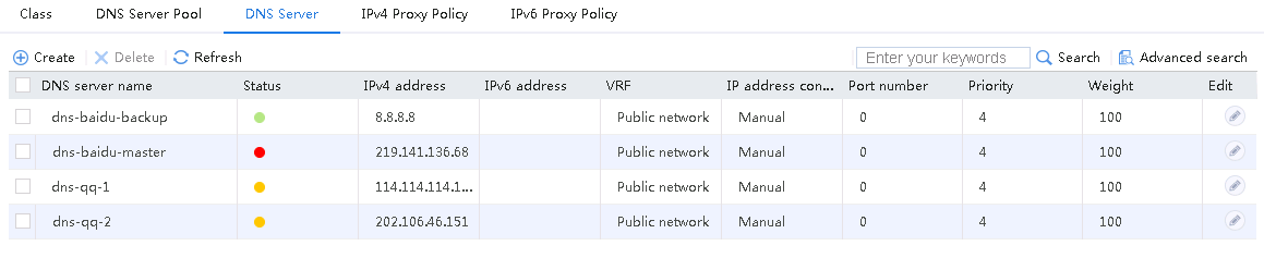
8. Use the client to send a DNS request to www.baidu.com.
9. View DNS server statistics to verify that the DNS request is sent to backup DNS server dns-baidu-backup with a lower priority, because DNS server dns-baidu-master is unavailable.
Figure 234 DNS server statistics after link link-chinatel-master is shut down
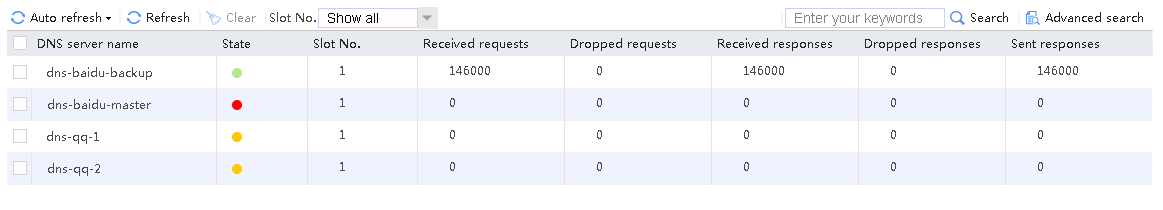
10. Use the client to send a DNS request to mail.qq.com.
11. View the DNS server status.
Figure 235 DNS server status
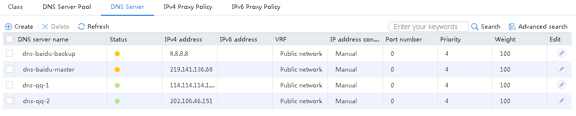
12. Navigate to the Monitor > Link Load Balancing > DNS Proxy Statistics > DNS Servers page.
13. View the DNS server statistics. DNS requests are evenly sent to both DNS servers.
Figure 236 DNS server statistics
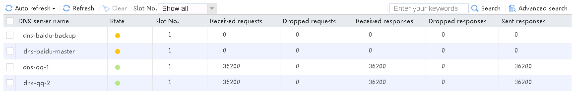
14. Shut down the outgoing interface of link link-cnc-1.
15. Viewing the link status.
Figure 237 Link status after link link-cnc-1 is shut down
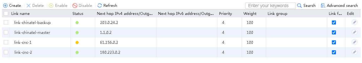
16. View the DNS server status.
Figure 238 DNS server status after link link-cnc-1 is shut down

17. Use the client to send a DNS request to mail.qq.com.
18. View DNS server statistics to verify that the DNS request is sent to DNS server dns-qq-2, because DNS server dns-qq-1 is unavailable.
Figure 239 DNS server statistics
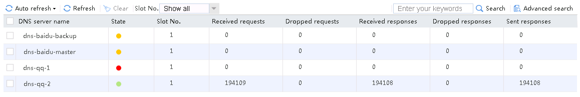
Configuration files
#
nqa template icmp icmp-cnc-1
next-hop ip 61.156.0.2
out interface Route-Aggregation1.100
#
nqa template icmp icmp-cnc-2
next-hop ip 180.223.0.2
out interface Route-Aggregation1.101
#
nqa template icmp icmp-chinatel-master
next-hop ip 1.1.0.2
out interface Route-Aggregation1.102
#
nqa template icmp icmp-chinatel-backup
next-hop ip 203.0.24.2
out interface Route-Aggregation1.103
#
nqa template dns dns114.114.114.114
destination ip 114.114.114.114
resolve-target mail.qq.com
ttl 255
#
nqa template dns dns202.106.46.151
destination ip 202.106.46.151
resolve-target mail.qq.com
ttl 255
#
nqa template dns dns219.141.136.68
destination ip 219.141.136.68
resolve-target www.baidu.com
ttl 255
#
nqa template dns dns8.8.8.8
destination ip 8.8.8.8
resolve-target www.baidu.com
ttl 255
#
loadbalance dns-server dns-qq-1
ip address 114.114.114.114
link link-cnc-1
#
loadbalance dns-server dns-qq-2
ip address 202.106.46.151
link link-cnc-2
#
loadbalance dns-server dns-baidu-master
ip address 219.141.136.68
link link-chinatel-master
#
loadbalance dns-server dns-baidu-backup
ip address 8.8.8.8
link link-chinatel-backup
#
loadbalance dns-server-pool dsp-qq
success-criteria at-least 1
dns-server dns-qq-1 port 0
success-criteria at-least 1
probe dns114.114.114.114
dns-server dns-qq-2 port 0
success-criteria at-least 1
probe dns202.106.46.151
#
loadbalance dns-server-pool dsp-baidu
success-criteria at-least 1
dns-server dns-baidu-backup port 0
success-criteria at-least 1
probe dns8.8.8.8
dns-server dns-baidu-master port 0
priority 8
success-criteria at-least 1
probe dns219.141.136.68
#
loadbalance class damian-baidu.com type dns match-any
match 1 domain-name www.baidu.com
#
loadbalance class domain-qq.com type dns match-any
match 1 domain-name mail.qq.com
#
loadbalance action ##defaultactionfordnsproxyipv4##%%autocreatedbyweb%% type dns
dns-server-pool dsp-qq
#
loadbalance action dp4#action#for#damian-baidu.com type dns
dns-server-pool dsp-baidu
#
loadbalance action dp4#action#for#domain-qq.com type dns
dns-server-pool dsp-qq
#
loadbalance policy ##defaultpolicyfordnsproxyipv4##%%autocreatedbyweb%% type dns
class domain-qq.com action dp4#action#for#domain-qq.com
class damian-baidu.com action dp4#action#for#damian-baidu.com
default-class action ##defaultactionfordnsproxyipv4##%%autocreatedbyweb%%
#
loadbalance link link-chinatel-backup
router ip 203.0.24.2
success-criteria at-least 1
probe icmp-chinatel-backup
#
loadbalance link link-chinatel-master
router ip 1.1.0.2
success-criteria at-least 1
probe icmp-chinatel-master
#
loadbalance link link-cnc-1
router ip 61.0.156.2
success-criteria at-least 1
probe icmp-cnc-1
#
loadbalance link link-cnc-2
router ip 180.223.0.2
success-criteria at-least 1
probe icmp-cnc-2
#
loadbalance dns-proxy ##defaultdpfordnsproxyipv4##%%autocreatedbyweb%% type udp
ip address 0.0.0.0 0
service enable
lb-policy ##defaultpolicyfordnsproxyipv4##%%autocreatedbyweb%%
#
nat address-group 1 name cnc-1
address 61.0.156.100 61.0.156.200
#
nat address-group 2 name cnc-2
address 180.223.0.100 180.223.0.200
#
nat address-group 3 name chinatel-master
address 1.1.0.100 1.1.0.200
#
nat address-group 4 name chinatel-backup
address 203.0.24.100 203.0.24.200
#
interface Route-Aggregation1.100
ip address 61.0.156.1 255.255.255.0
nat outbound address-group 1
vlan-type dot1q vid 191
#
interface Route-Aggregation1.101
ip address 180.223.0.1 255.255.255.0
nat outbound address-group 2
vlan-type dot1q vid 192
#
interface Route-Aggregation1.102
ip address 1.1.0.1 255.255.255.0
nat outbound address-group 3
vlan-type dot1q vid 193
#
interface Route-Aggregation1.103
ip address 203.0.24.1 255.255.255.0
nat outbound address-group 4
vlan-type dot1q vid 194
#
Intelligent DNS configuration examples
Overview
Intelligent DNS, also called inbound link load balancing, load balances traffic among the links from the external network to the internal network.
Link load balancing supports IPv4 and IPv6, but does not support IPv4-to-IPv6 packet translation.
The LB device is connected to the external network at Layer 3.
Example: Configuring intelligent DNS based on DNS records
Network configuration
As shown in Figure 240, the two ISPs provide four links. The LB module on the local DNS server resolves the DNS requests from external users to the internal server, and selects the optimal link for traffic from the external network to the internal server by using the intelligent DNS processing mechanism.
The following record types are supported in DNS:
· A (Address)—Indicates the IP address of a domain.
· AAAA (Address)—Points a domain or subdomain to an IPv6 address.
During DNS forward resolution, the LB device uses the records in the DNS forward zone to search for the host name mapped to the DNS domain name. You can configure the following records in a forward DNS zone:
· CNAME (Canonical Name)—Points a hostname to another hostname. These records are typically used to point multiple hosts to a single server. For example, an enterprise has one internal server with host name host.qq.com. It provides both Web and mail services. For convenient user access, you can configure CNAME records www.qq.com and mail.qq.com. No matter whether a user requests Web or mail services, the user accesses host.qq.com.
· MX (Mail Exchanger)—Directs emails to a mail server for the forward DNS zone.
· NS (Name Server)—Specifies the domain name of the name server for the forward DNS zone.
· SOA (Start of Authority)—Specifies authoritative information about the forward DNS zone.
· SRV (Service)—Specifies a host for specific services provided by the forward DNS zone.
· TXT (Text)—Contains text information for resources outside of the domain.
· PTR (Pointer Record)—Provides the domain name associated with an IP address. It is used in reverse DNS lookups.

Analysis
For inbound link load balancing based on DNS records, complete the following tasks:
· Configure interface addresses and enable the keeping the last hop feature to ensure that the reverse traffic is returned from the same link.
· Reference the ICMP-type health monitoring template for each link, and configure the next hop IP address and the outgoing interface in the template.
· To receive DNS requests, configure links and DNS listener.
· Configure a forward DNS zone and a reverse DNS zone.
· To return IP addresses mapped to a domain name, configure a virtual server of the IP type.
· Configure DNS mapping and configure the virtual server list and the links corresponding to the virtual servers in the DNS mapping.
· Configure a forward DNS zone to resolve all types of records.
Software version used
This configuration example was created and verified on Alpha 1160P16 of L1000-AK325.
Restrictions and guidelines
Before configuration, make sure the external network is reachable to the LB device and DNS listener.
Procedure
Assigning IP addresses to interfaces
Details not shown.
Configuring a health monitoring template of the ICMP type
1. Navigate to the LB > Global Configuration > Health Monitoring page, and then click Create.
Figure 241 Configuring health monitoring template icmp-cnc-1 of the ICMP type

2. Click OK.
Figure 242 Configuring health monitoring template icmp-cnc-2 of the ICMP type

3. Click OK.
Figure 243 Configuring health monitoring template icmp-chinatel-master of the ICMP type

4. Click OK.
Figure 244 Configuring health monitoring template icmp-chinatel-backup of the ICMP type

5. Click OK.
Configuring links
1. Navigate to the LB > Global Configuration > Links page, and then click Create. Create link link-cnc-1, configure the next hop address as 61.156.0.2 and the probe method as icmp-cnc-1.
Figure 245 Creating link link-cnc-1


2. Click OK.
3. Create links link-cnc-2, link-chinatel-master, and link-chinatel-backup in the same way link link-cnc-1 is created.
Configuring a virtual server
1. Navigate to the LB > Application Load Balancing > Virtual Servers page, and then click Create. Create virtual server vs-cnc-1 with the type set to IP and the virtual server IPv4 address to 183.232.98.190.
Figure 246 Creating a virtual server
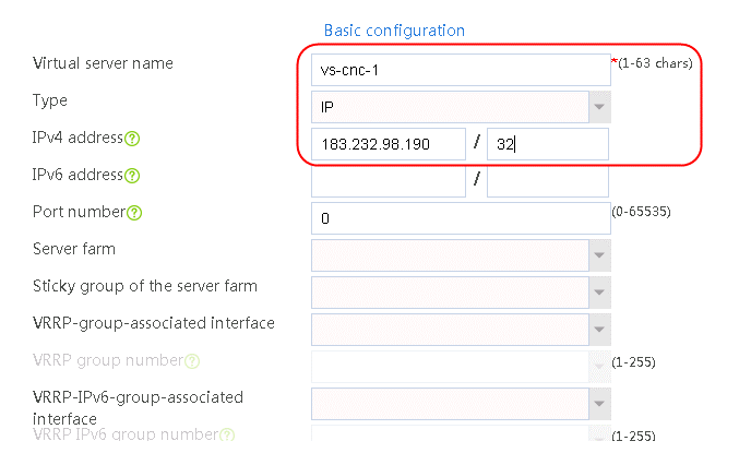
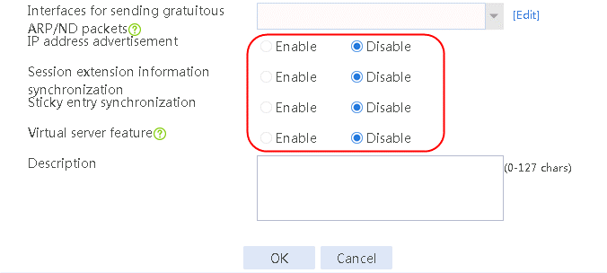
2. Click OK.
3. Create the virtual servers vs-cnc-2 and vs-cnc-ipv6 in the same way virtual server vs-cnc-1 is created.
Configuring a DNS listener
1. Navigate to the LB > Intelligent DNS > Local Intelligent DNS > DNS Listener page, and then click Create. Specify the DNS listener name as dl-cnc-1, and the DNS listener IPv4 address as 61.156.0.1. Enable the DNS listening feature.
Figure 247 Creating DNS listener dl-cnc-1

2. Click OK.
3. Create DNS listeners dl-cnc-2, dl-chinatel-m, and dl-chinatel-b in the same way DNS listener dl-cnc-1 is created.
Configuring a DNS mapping
1. Navigate to the LB > Intelligent DNS > Local Intelligent DNS > DNS Mapping, and then click Create. Specify the DNS mapping name as dm. Add domain names host.qq.com, ns-cnc1.baidu.com, and ns-tel1.baidu.com, create a virtual IP/virtual server list, set Preferred predictor to Weighted round robin, Alternative predictor to Random, and Backup predictor to Weighted least connections, and enable DNS mapping.
Figure 248 Creating DNS mapping dm
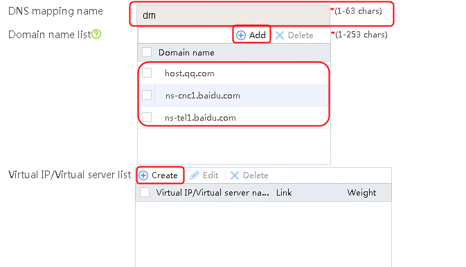
2. Click Create next to the virtual IP/virtual server list to add virtual server vs-cnc-1 and select link link-cnc-1.
Figure 249 Adding virtual server vs-cnc-1
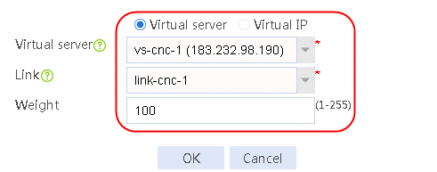
3. Click Create next to the virtual IP/virtual server list to add virtual server vs-cnc-2 and select link link-cnc-2.
Figure 250 Adding virtual server vs-cnc-2
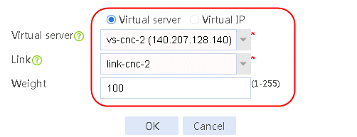
4. Click Create next to the virtual IP/virtual server list to add virtual server vs-cnc-ipv6 and select link link-cnc-1.
Figure 251 Adding virtual server vs-cnc-ipv6
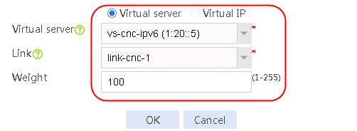
5. Create the virtual IP/virtual server list as follows: set Preferred predictor to Weighted round robin, Alternative predictor to Random, and Backup predictor to Weighted least connections, and enable DNS mapping.
Figure 252 Viewing the virtual IP/virtual server list and enabling DNS mapping
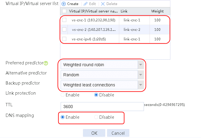
6. Click OK.
Configuring a DNS zone
1. Configure the MX records.
2. Navigate to the LB > Intelligent DNS > Local Intelligent DNS > Forward DNS Zone page, and then click Create. Specify the zone name as qq.com, the resource record type as MX, and the mail server host name as mail.
You can specify an absolute domain name (ending with ".") or a relative domain name (not ending with "."). If you specify a relative domain name, the system will add the specified domain name automatically to the end of the relative domain name.
Figure 253 Creating a forward DNS zone
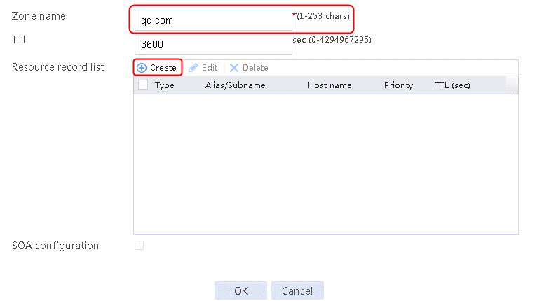
3. Click Create to add an MX resource record.
Figure 254 Adding an MX type resource record
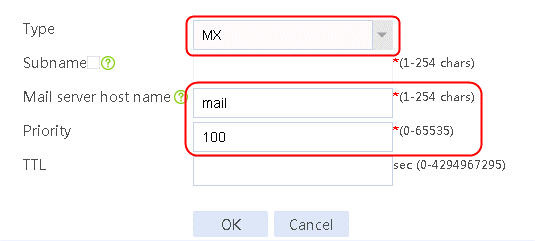
4. Click OK.
5. Navigate to the LB > Intelligent DNS > Local Intelligent DNS > Forward DNS Zone page, and then click Create.
6. Specify the zone name as qq.com, the resource record type as CNAME, the alias as mail, and the canonical name as host.
You can specify an absolute domain name (ending with ".") or a relative domain name (not ending with "."). If you specify a relative domain name, the system will add the specified domain name automatically to the end of the relative domain name.
7. Click Create to add a CNAME resource record.
Figure 255 Adding a CNAME type resource record 1
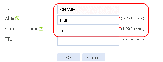
8. Click OK.
9. Click Create. Specify the resource record type as CNAME, the alias as www, and the canonical name as host.
Figure 256 Adding a CNAME type resource record
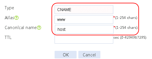
10. Click OK.
11. Navigate to the LB > Intelligent DNS > Local Intelligent DNS > Forward DNS Zone page, and then click Create.
12. Specify the zone name as baidu.com, the resource record type as NS, and the authoritative name server host names as ns-cnc1 and ns-tel1. In the SOA configuration, specify the primary name server host name as www and the administrator email address as www.
You can specify an absolute domain name (ending with ".") or a relative domain name (not ending with "."). If you specify a relative domain name, the system will add the specified domain name automatically to the end of the relative domain name.
13. Configure a CNAME type resource record with the alias mail and the canonical name host.
Figure 257 Creating a forward DNS zone
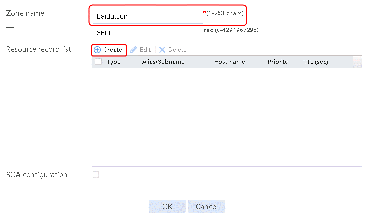
14. Click Create to add an NS resource record.
Figure 258 Adding NS type resource record 1
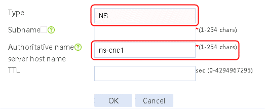
15. Click OK.
Figure 259 Adding NS type resource record 2
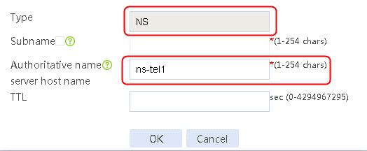
16. Click OK.
17. Configure SOA for DNS zone baidu.com.
Figure 260 Configuring SOA
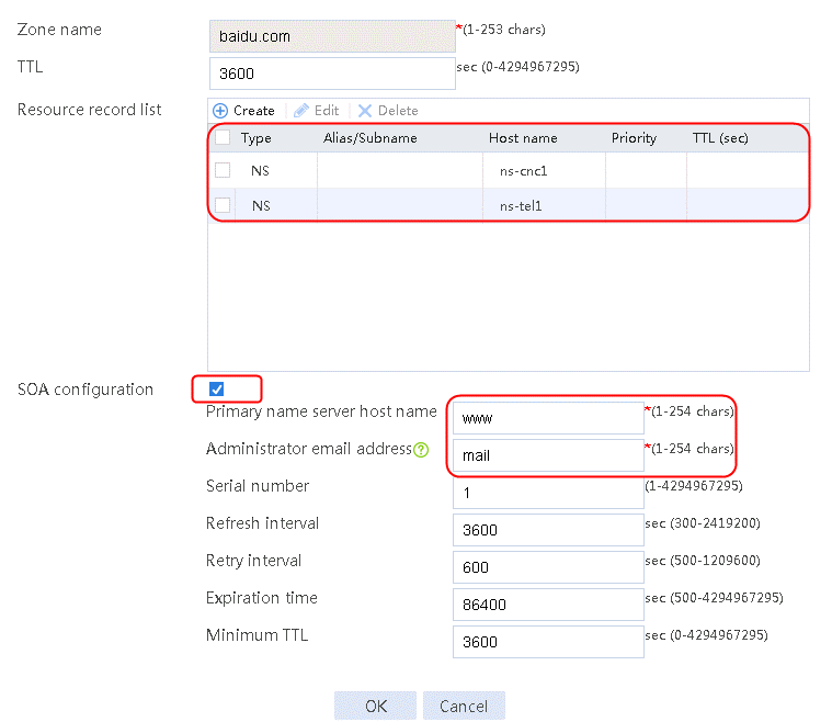
18. Click OK.
19. Configure SRV records.
Not available in the Web interface. The following uses the configuration at the CLI as an example.
You can specify an absolute domain name (ending with ".") or a relative domain name (not ending with "."). If you specify a relative domain name, the system will add the specified domain name automatically to the end of the relative domain name.
[sysname-lb-zone-qq.com] record srv service _ldap host-offering-service _tcp priority 50 weight 50 port 389
[sysname-lb-zone-qq.com]record srv service _ldap.qq.com. host-offering-service _tcp. priority 10 weight 10 port 80
#
20. Configure TXT records.
Not available in the Web interface. The following uses the configuration at the CLI as an example.
You can specify an absolute domain name (ending with ".") or a relative domain name (not ending with "."). If you specify a relative domain name, the system will add the specified domain name automatically to the end of the relative domain name.
[sysname-lb-zone-qq.com] record txt describe-txt 111111111111111111
[sysname-lb-zone-qq.com]record txt sub hotline describe-txt "v=spf1 include:spf.abcmail.abc.com.cn -all"
21. Configure a reverse DNS zone.
22. Navigate to the LB > Intelligent DNS > Local Intelligent DNS > Reverse DNS Zone page, and then click Create.
Figure 261 Creating a reverse DNS zone
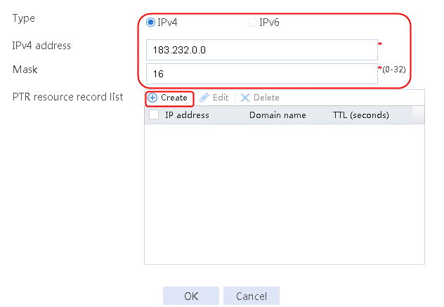
23. Click Create to add a PTR resource record list.
Figure 262 Adding a PTR type resource record
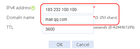
24. Click OK.
Figure 263 Configuring the reverse DNS zone
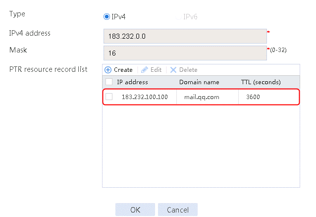
25. Click OK.
Verifying the configuration
1. View CNAME records through nslookup.
Figure 264 Viewing CNAME records through nslookup
2. View the A and AAAA records through nslookup.
The domain name is not in the mapping list. Look up the resource records in the forward DNS zone for the host name. With the host name, look up the virtual server IP address corresponding to the domain name in the DNS mapping.
Figure 265 Viewing the A records through nslookup
Figure 266 Viewing the AAAA records through nslookup
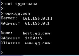
3. View the MX records through nslookup.
Figure 267 Viewing the MX records through nslookup
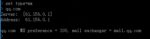
4. View the NS and SOA records through nslookup.
Figure 268 Viewing the NS records through nslookup
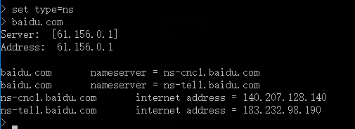
Figure 269 Viewing the SOA records through nslookup
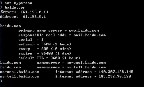
5. View the SRV records through nslookup.
Configure two SRV records to verify the return values of the relative domain name and absolute domain name.
Figure 270 Viewing the SRV records through nslookup
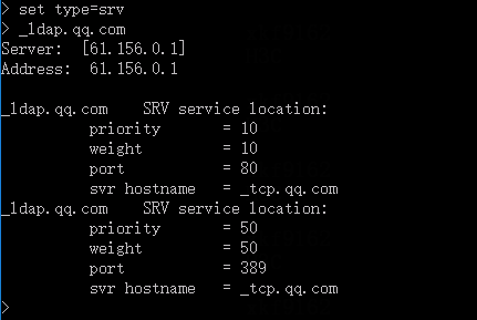
6. View the TXT records through nslookup.
Configure two TXT records in forward DNS zone qq.com. One is configured with sub, and the other one is not. View the TXT records.
Figure 271 Viewing the TXT records through nslookup
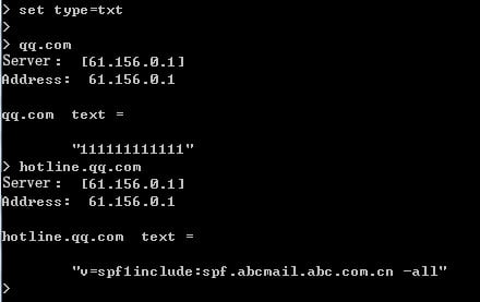
7. View the PTR records through nslookup.
Figure 272 Viewing the PTR records through nslookup
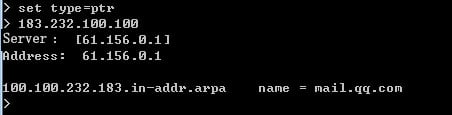
Configuration files
interface Route-Aggregation1.100
port link-mode route
ip address 61.156.0.1 255.255.0.0
ip last-hop hold
#
interface Route-Aggregation1.101
port link-mode route
ip address 180.223.0.1 255.255.0.0
ip last-hop hold
#
interface Route-Aggregation1.102
port link-mode route
ip address 1.1.0.1 255.255.0.0
ip last-hop hold
#
interface T Route-Aggregation1.103
port link-mode route
ip address 203.0.24.1 255.255.0.0
ip last-hop hold
#
nqa template icmp icmp-cnc-1
next-hop ip 61.156.0.2
out interface Route-Aggregation1.100
#
nqa template icmp icmp-cnc-2
next-hop ip 180.223.0.2
out interface Route-Aggregation1.101
#
nqa template icmp icmp-chinatel-master
next-hop ip 1.1.0.2
out interface Route-Aggregation1.102
#
nqa template icmp icmp-chinatel-backup
next-hop ip 203.0.24.2
out interface Route-Aggregation1.103
#
loadbalance link link-cnc-1
router ip 61.156.0.2
success-criteria at-least 1
probe icmp-cnc-1
#
loadbalance link link-cnc-2
router ip 180.223.0.2
success-criteria at-least 1
probe icmp-cnc-2
#
loadbalance link link-chinatel-master
router ip 1.1.0.2
success-criteria at-least 1
probe icmp-chinatel-master
#
loadbalance link link-chinatel-backup
router ip 203.0.24.2
success-criteria at-least 1
probe icmp-chinatel-backup
#
virtual-server vs-cnc-1 type ip
virtual ip address 183.232.98.190
#
virtual-server vs-cnc-2 type ip
virtual ip address 140.207.128.140
#
virtual-server vs-cnc-ipv6 type ip
virtual ipv6 address 1:20::5
#
loadbalance virtual-server-pool dm
predictor alternate random
predictor fallback least-connection
virtual-server vs-cnc-ipv6 link link-cnc-1
virtual-server vs-cnc1 link link-cnc-1
virtual-server vs-cnc2 link link-cnc-2
#
loadbalance dns-listener dl-cnc-1
ip address 61.156.0.1
service enable
#
loadbalance dns-listener dl-cnc-2
ip address 180.223.0.1
service enable
#
loadbalance dns-listener dl-chinatel-m
ip address 1.1.0.1
service enable
#
loadbalance dns-listener dl-chinatel-b
ip address 203.0.24.1
service enable
#
loadbalance dns-map dm
domain-name host.qq.com
domain-name ns-cnc1.baidu.com
domain-name ns-tel1.baidu.com
service enable
virtual-server-pool dm
#
loadbalance zone baidu.com
record ns authority ns-cnc1
record ns authority ns-tel1
soa
primary-nameserver www
responsible-mail mail
#
loadbalance zone qq.com
record mx exchanger mail preference 100
record cname alias mail canonical host
record cname alias www canonical host
record txt describe-txt 111111111111
record txt sub hotline describe-txt "v=spf1 include:spf.abcmail.abc.com.cn -all"
record srv service _ldap host-offering-service _tcp priority 50 weight 50 port 389
record srv service _ldap.qq.com. host-offering-service _tcp. priority 10 weight 10 port 80
#
loadbalance reverse-zone ip 183.232.0.0 16
record ptr ip 183.232.100.100 mail.qq.com
#
Example: Configuring dynamic proximity-based intelligent DNS
Network configuration
In Figure 273, the two ISPs provide four links, with different router hop count, bandwidth, and cost. Configure dynamic proximity-based intelligent DNS for the LB device to select the optimal link to a destination. If no proximity information for a destination is available, the load balancing module selects a link based on the scheduling algorithm.
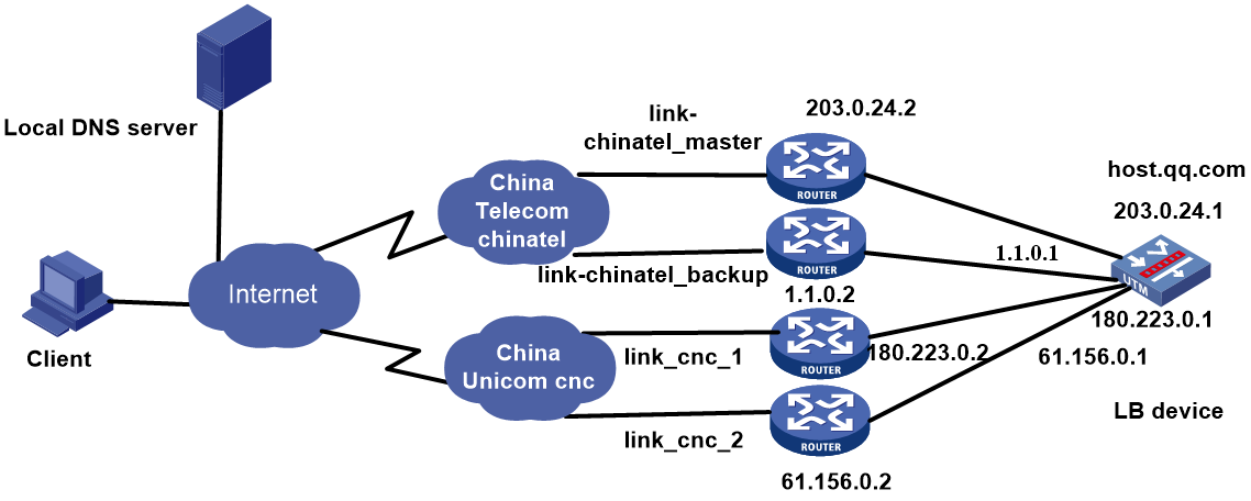
Analysis
For dynamic proximity-based intelligent DNS, complete the following tasks:
· Configure interface addresses and enable the keeping the last hop feature to ensure that the reverse traffic is returned from the same link.
· Reference the ICMP-type health monitoring template for each link, and configure the next hop IP address and the outgoing interface in the template.
· To receive DNS requests, configure links and DNS listener.
· To return IP addresses mapped to a domain name, configure a virtual server of the IP type.
· Configure DNS mapping, and configure the virtual server list and the links corresponding to the virtual servers in the DNS mapping.
· Configure proximity parameters.
Software version used
This configuration example was created and verified on Alpha 1160P16 of L1000-AK325.
Restrictions and guidelines
When you configure dynamic proximity-based intelligent DNS, follow these restrictions and guidelines:
· Before configuration, make sure the external network is reachable to the LB device and DNS listener.
· The destination IP address of dynamic detection is the original probe address. The current best link is obtained through the proximity algorithm, and the detection period is user configured.
· The optimal link that the LB device selects depends on the link status.
· As a best practice to avoid service failure), select a scheduling algorithm other than dynamic proximity as the secondary algorithm in the DNS mapping. Dynamic proximity entries are triggered by packets, and available proximity entries can be generated only 10 seconds after a successful detection.
Procedure
Assigning IP addresses to interfaces
Details not shown.
Configuring a health monitoring template of the ICMP type
1. Navigate to the LB > Global Configuration > Health Monitoring page, and then click Create.
Figure 274 Configuring health monitoring template icmp-cnc-1 of the ICMP type

2. Click OK.
Figure 275 Configuring health monitoring template icmp-cnc-2 of the ICMP type
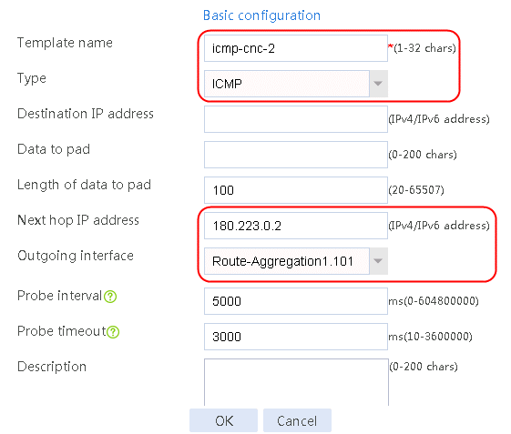
3. Click OK.
Figure 276 Configuring health monitoring template icmp-chinatel-master of the ICMP type

4. Click OK.
Figure 277 Configuring health monitoring template icmp-chinatel-backup of the ICMP type
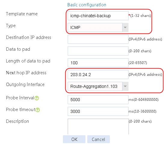
5. Click OK.
Configuring links
1. Navigate to the LB > Global Configuration > Links page, and then click Create. Create link link-cnc-1, configure the next hop IP address as 61.156.0.2, the link cost for proximity calculation as 40, and the probe method as icmp-cnc-1.
Figure 278 Creating link link-cnc-1
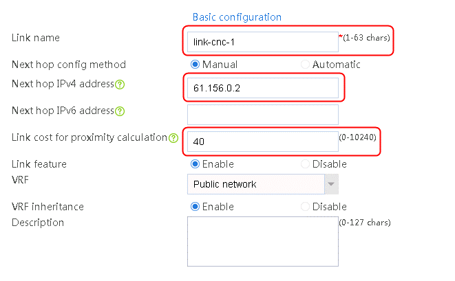

2. Click OK.
3. Create links link-cnc-2, link-chinatel-master, and link-chinatel-backup in the same way link link-cnc-1 is created.
Configuring a virtual server
1. Navigate to the LB > Application Load Balancing > Virtual Servers page, and then click Create. Create virtual server vs-cnc-1 with the type set to IP and the virtual server IPv4 address to 183.232.98.190.
Figure 279 Creating virtual server vs-cnc-1


2. Click OK.
3. Create virtual servers vs-cnc-2, vs-chinatel-m, and vs-chinatel-b in the same way virtual server vs-cnc-1 is created.
Configuring an ISP
1. Navigate to the LB > Global Configuration > LSP page, click Select, select an ISP file, and then click Import.
Figure 280 Importing an ISP file

2. Click Apply.
Configuring a region
1. Navigate to the LB > Public Configuration > Regions page, and then click Create. Specify the region names as region-chinatel and region-cnc. Select chinatel and cnc respectively for ISP and click Add.
Figure 281 Creating region region-chinatel
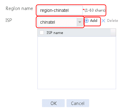
2. Select chinatel for ISP and click Add.
Figure 282 Configuring region region-chinatel
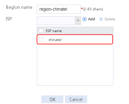
3. Click OK.
Figure 283 Creating region region-cnc

4. Select cnc for ISP and click Add.
Figure 284 Configuring region region-cnc

5. Click OK.
Configuring static proximity
1. Navigate to the LB > Intelligent DNS > Local Intelligent DNS > Static Proximity page, and then click Create.
Figure 285 Creating region region-chinatel static proximity 1

2. Click OK.
Figure 286 Creating region region-chinatel static proximity 2

3. Click OK.
Figure 287 Creating region region-cnc static proximity 1
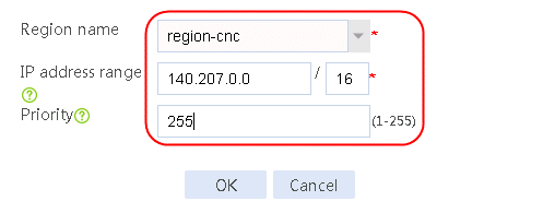
4. Click OK.
Figure 288 Creating region region-cnc static proximity 2

5. Click OK.
Configuring a DNS listener
1. Navigate to the LB > Intelligent DNS > Local Intelligent DNS > DNS Listener page, and then click Create. Specify the DNS listener name as dl-cnc-1, and the DNS listener IPv4 address as 61.156.0.1. Enable the DNS listening feature.
Figure 289 Creating DNS listener dl-cnc-1
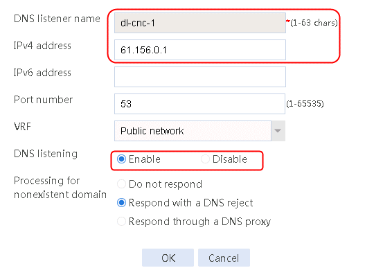
2. Click OK.
3. Create DNS listeners dl-cnc-2, dl-chinatel-m, and dl-chinatel-b in the same way DNS listener dl-cnc-1 is created.
Configuring a DNS mapping
1. Navigate to the LB > Intelligent DNS > Local Intelligent DNS > DNS Mapping page, and then click Create. Specify the DNS mapping name as dm. Add domain name host.qq.com, create a virtual IP/virtual server list, set Preferred predictor to Dynamic Proximity, Alternative predictor to Static Proximity and Backup predictor to Weighted round robin, and enable DNS mapping.
Figure 290 Creating DNS mapping dm
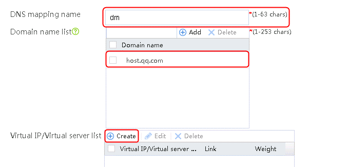
2. Click Create next to the virtual IP/virtual server list to add virtual server vs-cnc-1. Select link link-cnc-1 and specify weight 100.
Figure 291 Adding virtual server vs-cnc-1

3. Click Create next to the virtual IP/virtual server list to add virtual server vs-cnc-2. Select link link-cnc-2 and specify weight 10.
Figure 292 Adding virtual server vs-cnc-2
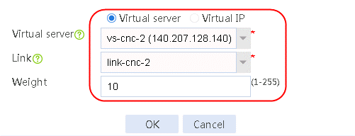
4. Click Create next to the virtual IP/virtual server list to add virtual server vs-chinatel-m. Select link link-chinatel-master and specify weight 100.
Figure 293 Adding virtual server vs-chinatel-m

5. Click Create next to the virtual IP/virtual server list to add virtual server vs-chinatel-b. Specify link link-chinatel-backup and specify weight 100.
Figure 294 Adding virtual server vs-chinatel-b
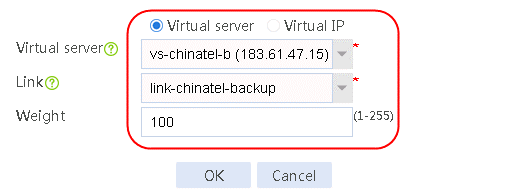
6. View the virtual IP/virtual server list as follows. Set Preferred predictor to Dynamic proximity, Alternative predictor to Static proximity and Backup predictor to Weighted round robin, and enable the DNS mapping.
Figure 295 Configuring a DNS mapping dm
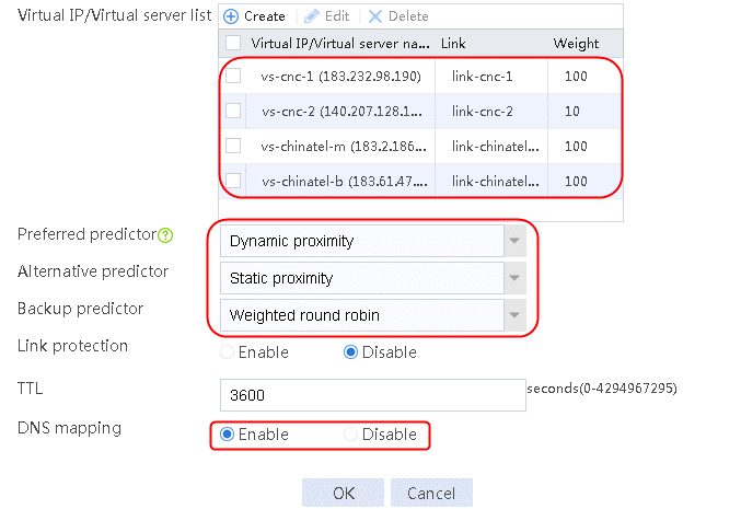
7. Click OK.
Configuring proximity parameters
1. Navigate to the LB > Global Configuration > Proximity > Proximity Parameter page, and then click Create.
Figure 296 Configuring proximity parameters

2. Click Create default probe template to configure proximity probe template icmp of the ICMP type.
Figure 297 Configuring a proximity probe template

3. Click OK.
Figure 298 Configuring proximity parameters

4. Click OK.
Verifying the configuration
1. View proximity entries to verify that the alternative proximity algorithm will be used if the preferred proximity algorithm does not take effect, and IP address is 183.61.47.15 is returned when no optimal link is generated.
Figure 299 Viewing proximity entry 1

Figure 300 Viewing the returned IP address
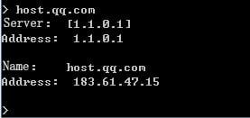
2. Verify that the preferred proximity algorithm takes effect and IP address 183.2.186.153 is returned when an optimal link is generated.
Figure 301 Viewing proximity entry 2

Figure 302 Viewing the returned IP address
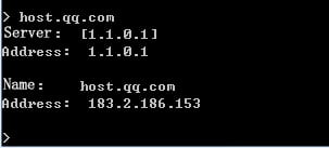
Configuration files
#
interface Route-Aggregation1.100
port link-mode route
ip address 61.156.0.1 255.255.0.0
ip last-hop hold
interface Route-Aggregation1.101
port link-mode route
ip address 180.223.0.1 255.255.0.0
ip last-hop hold
interface Route-Aggregation1.102
port link-mode route
ip address 1.1.0.1 255.255.0.0
ip last-hop hold
interface Route-Aggregation1.103
port link-mode route
ip address 203.0.24.1 255.255.0.0
ip last-hop hold
#
nqa template icmp icmp-cnc-1
next-hop ip 61.156.0.2
out interface Route-Aggregation1.100
#
nqa template icmp icmp-cnc-2
next-hop ip 180.223.0.2
out interface Route-Aggregation1.101
#
nqa template icmp icmp-chinatel-master
next-hop ip 1.1.0.2
out interface Route-Aggregation1.102
#
nqa template icmp icmp-chinatel-backup
next-hop ip 203.0.24.2
out interface Route-Aggregation1.103
#
loadbalance link link-cnc-1
router ip 61.156.0.2
cost 40
success-criteria at-least 1
probe icmp-cnc-1
#
loadbalance link link-cnc-2
router ip 180.223.0.2
cost 100
success-criteria at-least 1
probe icmp-cnc-2
#
loadbalance link link-chinatel-master
router ip 1.1.0.2
success-criteria at-least 1
probe icmp-chinatel-master
#
loadbalance link link-chinatel-backup
router ip 203.0.24.2
cost 200
success-criteria at-least 1
probe icmp-chinatel-backup
#
virtual-server vs-cnc-1 type ip
virtual ip address 183.232.98.190
#
virtual-server vs-cnc-2 type ip
virtual ip address 140.207.128.140
#
virtual-server vs-chinatel-m type ip
virtual ip address 183.2.186.153
#
virtual-server vs-chinatel-b type ip
virtual ip address 183.61.47.15
#
loadbalance isp file lbispinfo-v1.7.tp
#
loadbalance region region-chinatel
isp chinatel
#
loadbalance region region-cnc
isp cnc
#
topology region region-chinatel ip 183.2.0.0 16 priority 255
topology region region-chinatel ip 183.61.0.0 16
topology region region-cnc ip 140.207.0.0 16 priority 255
topology region region-cnc ip 183.232.0.0 16
#
loadbalance virtual-server-pool dm
predictor preferred proximity
predictor alternate round-robin
predictor fallback topology
virtual-server vs-chinatel-b link link-chinatel-backup
virtual-server vs-chinatel-m link link-chinatel-master
virtual-server vs-cnc1 link link-cnc-1
virtual-server vs-cnc2 link link-cnc-2 weight 10
#
loadbalance dns-listener dl-cnc-1
ip address 61.156.0.1
service enable
#
loadbalance dns-listener dl-cnc-2
ip address 180.223.0.1
service enable
#
loadbalance dns-listener dl-chinatel-m
ip address 1.1.0.1
service enable
#
loadbalance dns-listener dl-chinatel-b
ip address 203.0.24.1
service enable
#
loadbalance dns-map dm
domain-name host.qq.com
service enable
virtual-server-pool dm
#
loadbalance proximity
match default lb-probe icmp
#
Example: Configuring static proximity-based intelligent DNS (virtual service)
Network configuration
In Figure 273, the two ISPs provide four links, with the same router hop count, bandwidth, and cost. Configure static proximity-based intelligent DNS for the LB device to select the optimal link based on link status.
When a China Unicom user accesses host.qq.com, the China Unicom server IP address segments 183.232.x.x and 140.207.128.140 are returned. The 183.232.x.x segment contains two IP addresses: 183.232.98.190 and 183.232.100.100. When a China Telecom user accesses host.qq.com, the returned IP address is China Telecom server IP address 183.2.186.153 if the primary link link-chinatel-master is operating correctly. If the primary link is not available, the returned IP address is China Unicom server IP address 183.61.47.15.
Figure 303 Network diagram

Analysis
For static proximity-based intelligent DNS, complete the following tasks:
· Configure interface addresses and enable the keeping the last hop feature to ensure that the reverse traffic is returned from the same link.
· Reference the ICMP-type health monitoring template for each link, and configure the next hop IP address and the outgoing interface in the template.
· To receive DNS requests, configure links and DNS listener.
· To return IP addresses mapped to a domain name, configure a virtual server of the IP type.
· Configure DNS mapping, and configure the virtual server list and the links corresponding to the virtual servers in the DNS mapping.
· For users to access the server of an ISP, select the static proximity algorithm as the preferred scheduling algorithm for the virtual IP address pool.
Software version used
This configuration example was created and verified on Alpha 1160P16 of L1000-AK325.
Restrictions and guidelines
When you configure static proximity-based intelligent DNS, follow these restrictions and guidelines:
· Before configuration, make sure the external network is reachable to the LB device and DNS listener.
· Import the most recent ISP file:
a. Access the H3C website at http://www.h3c.com/.
b. Navigate to the Support > Resource Center > Software Download > Security > Load Balancing > Comware V7 series > H3C ISP File page to download the file. After download, this file can be imported. Alternatively, you can upload an ISP file, and import the file by executing the loadbalance isp file command at the CLI to import the file to the device.
Procedure
Assigning IP addresses to interfaces
Details not shown.
Configuring a health monitoring template of the ICMP type
1. Navigate to the LB > Global Configuration > Health Monitoring page, and then click Create.
Figure 304 Configuring health monitoring template icmp-cnc-1 of the ICMP type

2. Click OK.
Figure 305 Configuring health monitoring template icmp-cnc-2 of the ICMP type

3. Click OK.
Figure 306 Configuring health monitoring template icmp-chinatel-master of the ICMP type

4. Click OK.
Figure 307 Configuring health monitoring template icmp-chinatel-backup of the ICMP type

5. Click OK.
Configuring links
1. Navigate to the LB > Global Configuration > Links page, and then click Create. Create link link-cnc-1, configure the next hop address as 61.156.0.2 and the probe method as icmp-cnc-1.
Figure 308 Creating link link-cnc-1


2. Click OK.
3. Create links link-cnc-2, link-chinatel-master, and link-chinatel-backup in the same way link link-cnc-1 is created.
Configuring a virtual server
1. Navigate to the LB > Application Load Balancing > Virtual Servers page, and then click Create. Create virtual server vs-cnc-1 with the type set to IP and the virtual server IPv4 address to 183.232.98.190.
Figure 309 Creating virtual server vs-cnc-1


2. Click OK.
3. Create virtual servers vs-cnc1-02, vs-chinatel-m, and vs-chinatel-b in the same way virtual server vs-cnc-1 is created.
Configuring an ISP
1. Navigate to the LB > Global Configuration > LSP page, click Select, select an ISP file, and then click Import.
Figure 310 Importing an ISP file

2. Click Import.
Configuring a region
1. Navigate to the LB > Public Configuration > Regions page, and then click Create. Specify the region names as region-chinatel and region-cnc. Select chinatel and cnc respectively for ISP and click Add.
Figure 311 Creating region region-chinatel

2. Select chinatel for ISP and click Add.
Figure 312 Configuring region region-chinatel

3. Click OK.
Figure 313 Creating region region-cnc
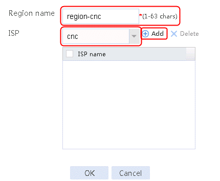
4. Select cnc for ISP and click Add.
Figure 314 Configuring region region-cnc

5. Click OK.
Configuring static proximity
1. Navigate to the LB > Intelligent DNS > Local Intelligent DNS > Static Proximity page, and then click Create.
Figure 315 Creating region region-chinatel static proximity 1

2. Click OK.
Figure 316 Creating region region-chinatel static proximity 2

3. Click OK.
Figure 317 Creating region region-cnc static proximity 1

4. Click OK.
Figure 318 Creating region region-cnc static proximity 2

5. Click OK.
Configuring a DNS listener
1. Navigate to the LB > Intelligent DNS > Local Intelligent DNS > DNS Listener page, and then click Create. Specify the DNS listener name as dl-cnc-1, and the DNS listener IPv4 address as 61.156.0.1. Enable the DNS listening feature.
Figure 319 Creating DNS listener dl-cnc-1

2. Click OK.
3. Create DNS listeners dl-cnc-2, dl-chinatel-m, and dl-chinatel-b in the same way DNS listener dl-cnc-1 is created.
Configuring a DNS mapping
1. Navigate to the LB > Intelligent DNS > Local Intelligent DNS > DNS Mapping page, and then click Create. Specify the DNS mapping name as dm. Add domain name host.qq.com, create a virtual IP/virtual server list, set Preferred predictor to Static proximity, Alternative predictor to Weighted least connection and Backup predictor to Random, and enable DNS mapping.
Figure 320 Creating DNS mapping dm

2. Click Create next to the virtual IP/virtual server list to add virtual server vs-cnc-1. Select link link-cnc-1 and specify weight 100.
Figure 321 Adding virtual server vs-cnc-1
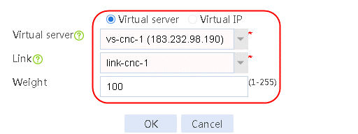
3. Click Create next to the virtual IP/virtual server list to add virtual server vs-cnc1-01. Select link link-cnc-1 and specify weight 10.
Figure 322 Adding virtual server vs-cnc1-01
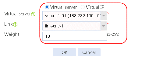
4. Click Create next to the virtual IP/virtual server list to add virtual server vs-cnc-2. Select link link-cnc-2 and specify weight 10.
Figure 323 Adding virtual server vs-cnc-2
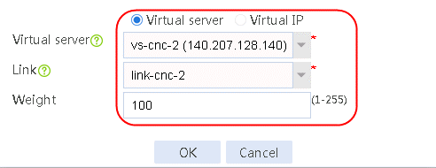
5. Click Create next to the virtual IP/virtual server list to add virtual server vs-chinatel-m. Select link link-chinatel-master and specify weight 100.
Figure 324 Adding virtual server vs-chinatel-m
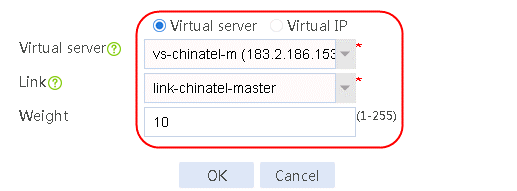
6. Click Create next to the virtual IP/virtual server list to add virtual server vs-chinatel-b. Select link link-chinatel-backup and specify weight 100.
Figure 325 Adding virtual server vs-chinatel-b

7. Set Preferred predictor to Static proximity, Alternative predictor to Static proximity and Backup predictor to Weighted round robin, and enable DNS mapping.
Figure 326 Configuring a DNS mapping dm
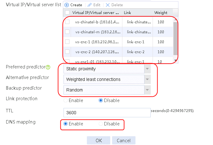
8. Click OK.
Verifying the configuration
Domain access by a China Unicom user
Verify that IP addresses 183.232.x.x (including 183.232.98.190 and 183.232.100.100) and 140.207.128.140 are returned in turn when a China Unicom user accesses host.qq.com. The ratio of the returned addresses is 10:1. A large number of packets are required to show the ratio of the returned addresses.
Figure 327 Access by a China Unicom user to domain host.qq.com
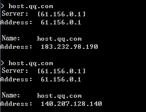
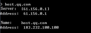
Access by a China Telecom user to domain host.qq.com
1. Verify that the IP address segment 183.2.186.153 is returned firstly when the primary link link-chinatel-master is available.
Figure 328 Viewing the link status
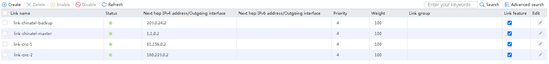
Figure 329 Access by a China Telecom user to domain host.qq.com when the primary link is available
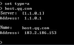
2. Use a large packet to repeatedly ping IP address 1.1.0.1 for the primary link link-chinatel-master to become busy. Verify that IP address segment 183.61.47.15 for the backup link link-chinatel-backup is returned.
Figure 330 Viewing the link status
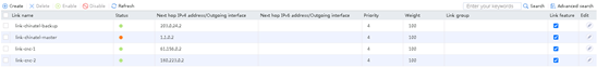
Figure 331 Access by a China Telecom user to domain host.qq.com when the primary link is unavailable
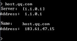
Configuration files
#
interface Route-Aggregation1.100
port link-mode route
ip address Route-Aggregation1.100
ip last-hop hold
interface Route-Aggregation1.101
port link-mode route
ip address 180.223.0.1 255.255.0.0
ip last-hop hold
interface Route-Aggregation1.102
port link-mode route
ip address 1.1.0.1 255.255.0.0
ip last-hop hold
interface Route-Aggregation1.103
port link-mode route
ip address 203.0.24.1 255.255.0.0
ip last-hop hold
#
nqa template icmp icmp-cnc-1
next-hop ip 61.156.0.2
out interface Route-Aggregation1.100
#
nqa template icmp icmp-cnc-2
next-hop ip 180.223.0.2
out interface Route-Aggregation1.101
#
nqa template icmp icmp-chinatel-master
next-hop ip 1.1.0.2
out interface Route-Aggregation1.102
#
nqa template icmp icmp-chinatel-backup
next-hop ip 203.0.24.2
out interface Route-Aggregation1.103
#
loadbalance link link-cnc-1
router ip 61.156.0.2
success-criteria at-least 1
probe icmp-cnc-1
#
loadbalance link link-cnc-2
router ip 180.223.0.2
success-criteria at-least 1
probe icmp-cnc-2
#
loadbalance link link-chinatel-master
router ip 1.1.0.2
success-criteria at-least 1
probe icmp-chinatel-master
#
loadbalance link link-chinatel-backup
router ip 203.0.24.2
success-criteria at-least 1
probe icmp-chinatel-backup
#
virtual-server vs-cnc-1 type ip
virtual ip address 183.232.98.190
#
virtual-server vs-cnc1-01 type ip
virtual ip address 183.232.100.100
#
virtual-server vs-cnc-2 type ip
virtual ip address 140.207.128.140
#
virtual-server vs-chinatel-m type ip
virtual ip address 183.2.186.153
#
virtual-server vs-chinatel-b type ip
virtual ip address 183.61.47.15
#
loadbalance virtual-server-pool dm
predictor preferred topology
predictor alternate least-connection
predictor fallback random
bandwidth busy-protection enable
virtual-server vs-chinatel-b link link-chinatel-backup
virtual-server vs-chinatel-m link link-chinatel-master
virtual-server vs-cnc1-01 link link-cnc-1 weight 10
virtual-server vs-cnc-1 link link-cnc-1
virtual-server vs-cnc-2 link link-cnc-2 weight 10
#
loadbalance isp file lbispinfo-v1.7.tp
#
loadbalance region region-chinatel
isp chinatel
#
loadbalance region region-cnc
isp cnc
#
topology region region-chinatel ip 183.2.0.0 16 priority 255
topology region region-chinatel ip 183.61.0.0 16
topology region region-cnc ip 140.207.0.0 16
topology region region-cnc ip 183.232.0.0 16
#
loadbalance dns-listener dl-cnc-1
ip address 61.156.0.1
service enable
#
loadbalance dns-listener dl-cnc-2
ip address 180.223.0.1
service enable
#
loadbalance dns-listener dl-chinatel-m
ip address 1.1.0.1
service enable
#
loadbalance dns-listener dl-chinatel-b
ip address 203.0.24.1
service enable
#
loadbalance dns-map dm
domain-name host.qq.com
service enable
virtual-server-pool dm
#
Example: Configuring inbound link load balancing based on virtual service pool
Network configuration
In Figure 332, the two ISPs provide four links, with the same router hop count, bandwidth, and cost. Configure static proximity-based intelligent DNS for the LB device to select the optimal link based on link status.
When a China Unicom user accesses host.qq.com, the China Unicom server IP address segments 183.232.x.x and 140.207.128.140 are returned. The 183.232.x.x segment contains two IP addresses: 183.232.98.190 and 183.232.100.100. When a China Telecom user accesses host.qq.com, the returned IP address is China Telecom server IP address 183.2.186.153 if the primary link link-chinatel-master is operating correctly. If the primary link is not available, the returned IP address is China Unicom server IP address 183.61.47.15.

Analysis
For static proximity-based intelligent DNS, complete the following tasks:
· Configure interface addresses and enable the keeping the last hop feature to ensure that the reverse traffic is returned from the same link.
· Reference the ICMP-type health monitoring template for each link, and configure the next hop IP address and the outgoing interface in the template.
· To receive DNS requests, configure links and DNS listener.
· To return IP addresses mapped to a domain name, configure a virtual server of the IP type.
· Configure DNS mapping, and configure the virtual server list and the links corresponding to the virtual servers in the DNS mapping.
· For users to access the server of an ISP, select the static proximity algorithm as the preferred scheduling algorithm for the virtual IP address pool.
Software version used
This configuration example was created and verified on Alpha 1160P16 of L1000-AK325.
Restrictions and guidelines
When you configure static proximity-based intelligent DNS, follow these restrictions and guidelines:
· Before configuration, make sure the external network is reachable to the LB device and DNS listener.
· Import the most recent ISP file:
Procedure
Assigning IP addresses to interfaces
Details not shown.
Configuring a health monitoring template of the ICMP type
1. Navigate to the LB > Global Configuration > Health Monitoring page, and then click Create.
Figure 333 Configuring health monitoring template icmp-cnc-1 of the ICMP type

2. Click OK.
Figure 334 Configuring health monitoring template icmp-cnc-2 of the ICMP type

3. Click OK.
Figure 335 Configuring health monitoring template icmp-chinatel-master of the ICMP type
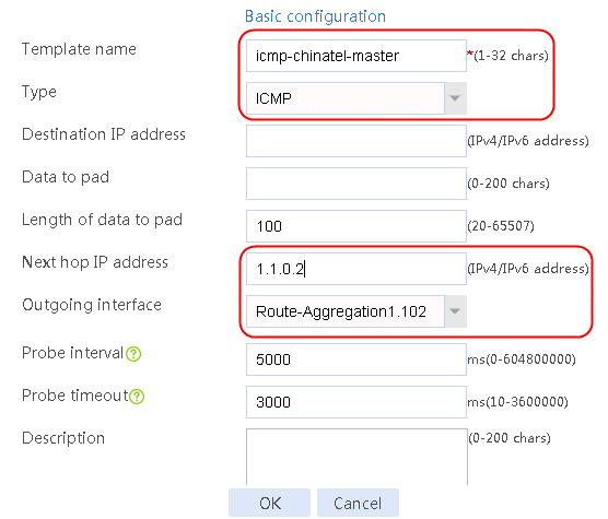
4. Click OK.
Figure 336 Configuring health monitoring template icmp-chinatel-backup of the ICMP type

5. Click OK.
Configuring links
1. Navigate to the LB > Global Configuration > Links page, and then click Create. Create link link-cnc-1, configure the next hop address as 61.156.0.2 and the probe method as icmp-cnc-1.
Figure 337 Creating link link-cnc-1
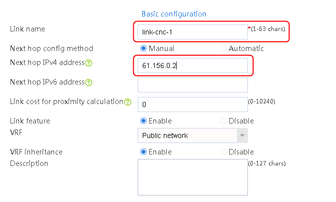
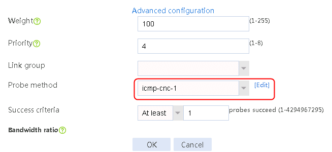
2. Click OK.
3. Create links link-cnc-2, link-chinatel-master, and link-chinatel-backup in the same way link link-cnc-1 is created.
Configuring a DNS mapping
1. Navigate to the LB > Intelligent DNS > Local Intelligent DNS > DNS Mapping page, and then click Create. Specify the DNS mapping name as dm. Add domain name host.qq.com, create a virtual IP/virtual server list, set Preferred predictor to Static proximity, Alternative predictor to Weighted least connections and Backup predictor to Random, and enable DNS mapping.
Figure 338 Creating DNS mapping dm

2. Click Create next to the virtual IP/virtual server list. Select Virtual IP in the dialog box that opens, configure the IP address as 183.232.98.190, associate link link-cnc-1, and click OK.
Figure 339 Configuring the virtual IP address of the associated link link-cnc-1
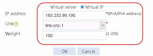
3. Click Create next to the virtual IP/virtual server list. Select Virtual IP in the dialog box that opens, configure the IP address as 183.232.100.100, associate link link-cnc-1, and click OK.
Figure 340 Configuring the virtual IP address of the associated link link-cnc-1

4. Click Create next to the virtual IP/virtual server list. Select Virtual IP in the dialog box that opens, configure the IP address as 140.207.128.140, associate link link-cnc-2, and click OK.
Figure 341 Configuring the virtual IP address of the associated link link-cnc-2
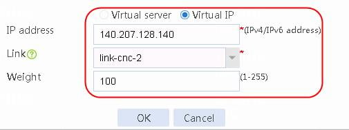
5. Click Create next to the virtual IP/virtual server list. Select Virtual IP in the dialog box that opens, configure the IP address as 183.2.186.153, associate link link-chinatel-master, and click OK.
Figure 342 Configuring the virtual IP address of the associated link link-chinatel-master
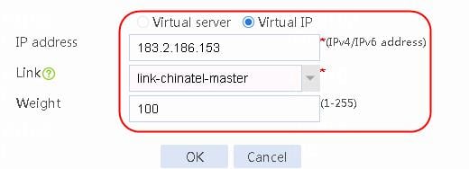
6. Click Create next to the virtual IP/virtual server list. Select Virtual IP in the dialog box that opens, configure the IP address as 183.61.47.15, associate link link-chinatel-backup, and click OK.
Figure 343 Configuring the virtual IP address of the associated link link-chinatel-backup
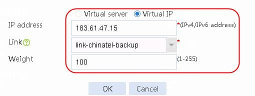
7. Set Preferred predictor to Static proximity, Alternative predictor to Weighted least connection and Backup predictor to Random, and enable DNS mapping.
Figure 344 Configuring the virtual IP/virtual server
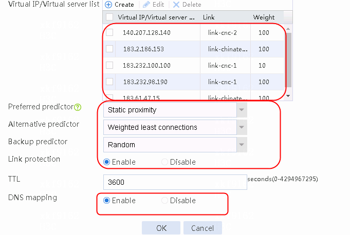
8. Click OK.
Configuring an ISP
1. Navigate to the LB > Global Configuration > LSP page, click Select, select an ISP file, and then click Import.
Figure 345 Importing an ISP file

2. Click Import.
Configuring a region
1. Navigate to the LB > Public Configuration > Regions page, and then click Create. Specify the region names as region-chinatel and region-cnc. Select chinatel and cnc respectively for ISP and click Add.
Figure 346 Creating region region-chinatel

2. Select chinatel for ISP and click Add.
Figure 347 Configuring region region-chinatel

3. Click OK.
Figure 348 Creating region region-cnc

4. Select cnc for ISP and click Add.
Figure 349 Configuring region region-cnc

5. Click OK.
Configuring static proximity
1. Navigate to the LB > Intelligent DNS > Local Intelligent DNS > Static Proximity page, and then click Create.
Figure 350 Creating region region-chinatel static proximity 1
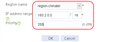
2. Click OK.
Figure 351 Creating region region-chinatel static proximity 2
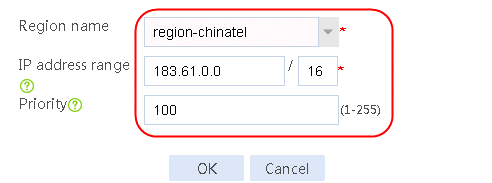
3. Click OK.
Figure 352 Creating region region-cnc static proximity 1
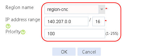
4. Click OK.
Figure 353 Creating region region-cnc static proximity 2
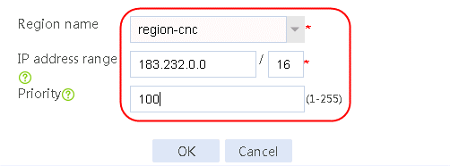
5. Click OK.
Configuring a DNS listener
1. Navigate to the LB > Intelligent DNS > Local Intelligent DNS > DNS Listener page, and then click Create. Specify the DNS listener name as dl-cnc-1, and the DNS listener IPv4 address as 61.156.0.1. Enable the DNS listening feature.
Figure 354 Creating DNS listener dl-cnc-1
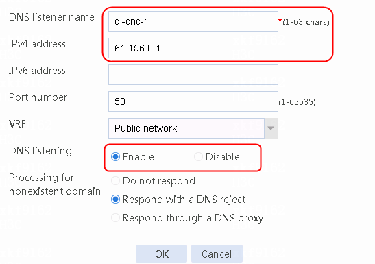
2. Click OK.
3. Create DNS listeners dl-cnc-2, dl-chinatel-m, and dl-chinatel-b in the same way DNS listener dl-cnc-1 is created.
Verifying the configuration
Domain access by a China Unicom user
Verify that IP addresses 183.232.x.x (including 183.232.98.190 and 183.232.100.100) and 140.207.128.140 are returned in turn when a China Unicom user accesses host.qq.com. The ratio of the returned addresses is 10:1. A large number of packets are required to show the ratio of the returned addresses.
Figure 355 Access by a China Unicom user to domain host.qq.com
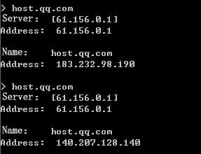

Access by a China Telecom user to domain host.qq.com
1. Verify that the IP address segment 183.2.186.153 is returned firstly when the primary link link-chinatel-master is available.
Figure 356 Viewing the link status
Figure 357 Access by a China Telecom user to domain host.qq.com when the primary link is available
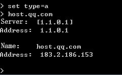
2. Use a large packet to repeatedly ping IP address 1.1.0.1 for the primary link link-chinatel-master to become busy. Verify that IP address segment 183.61.47.15 for the backup link link-chinatel-backup is returned.
Figure 358 Viewing the link status

Figure 359 Access by a China Telecom user to domain host.qq.com when the primary link is unavailable
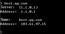
Configuration files
#
interface Route-Aggregation1.100
port link-mode route
ip address 61.156.0.1 255.255.0.0
ip last-hop hold
interface Route-Aggregation1.101
port link-mode route
ip address 180.223.0.1 255.255.0.0
ip last-hop hold
interface Route-Aggregation1.102
port link-mode route
ip address 1.1.0.1 255.255.0.0
ip last-hop hold
interface Route-Aggregation1.103
port link-mode route
ip address 203.0.24.1 255.255.0.0
ip last-hop hold
#
nqa template icmp icmp-cnc-1
next-hop ip 61.156.0.2
#
nqa template icmp icmp-cnc-2
next-hop ip 180.223.0.2
#
nqa template icmp icmp-chinatel-master
next-hop ip 1.1.0.2
#
nqa template icmp icmp-chinatel-backup
next-hop ip 203.0.24.2
#
loadbalance link link-cnc-1
router ip 61.156.0.2
success-criteria at-least 1
probe icmp-cnc-1
#
loadbalance link link-cnc-2
router ip 180.223.0.2
success-criteria at-least 1
probe icmp-cnc-2
#
loadbalance link link-chinatel-master
router ip 1.1.0.2
success-criteria at-least 1
probe icmp-chinatel-master
#
loadbalance link link-chinatel-backup
router ip 203.0.24.2
success-criteria at-least 1
probe icmp-chinatel-backup
#
loadbalance virtual-server-pool dm
predictor preferred topology
predictor alternate least-connection
predictor fallback random
bandwidth busy-protection enable
virtual-ip 140.207.128.140 link link-cnc-2
virtual-ip 183.2.186.153 link link-chinatel-master
virtual-ip 183.232.100.100 link link-cnc-1 weight 10
virtual-ip 183.232.98.190 link link-cnc-1
virtual-ip 183.61.47.15 link link-chinatel-backup
#
loadbalance isp file lbispinfo-v1.7.tp
#
loadbalance region region-chinatel
isp chinatel
#
loadbalance region region-cnc
isp cnc
#
topology region region-chinatel ip 183.2.0.0 16 priority 255
topology region region-chinatel ip 183.61.0.0 16
topology region region-cnc ip 140.207.0.0 16
topology region region-cnc ip 183.232.0.0 16
#
loadbalance dns-listener dl-cnc-1
ip address 61.156.0.1
service enable
#
loadbalance dns-listener dl-cnc-2
ip address 180.223.0.1
service enable
#
loadbalance dns-listener dl-chinatel-m
ip address 1.1.0.1
service enable
#
loadbalance dns-listener dl-chinatel-b
ip address 203.0.24.1
service enable
#
loadbalance dns-map dm
domain-name host.qq.com
service enable
virtual-server-pool dm
#