- Table of Contents
- Related Documents
-
| Title | Size | Download |
|---|---|---|
| 02-Application Load Balancing Configuration Examples | 13.13 MB |
Application Load Balancing Configuration Examples
Copyright © 2022 New H3C Technologies Co., Ltd. All rights reserved.
No part of this manual may be reproduced or transmitted in any form or by any means without prior written consent of New H3C Technologies Co., Ltd.
Except for the trademarks of New H3C Technologies Co., Ltd., any trademarks that may be mentioned in this document are the property of their respective owners.
The information in this document is subject to change without notice.
Contents
Application load balancing features
Layer 4 application load balancing configuration examples
Example: Configuring SNAT-based application load balancing
Example: Configuring source address-based application load balancing
Example: Configuring triangle transmission
Example: Configuring priority scheduling-based application load balancing
Example: Configuring Layer 4 application load balancing for high availability
Configuration files on the active device
Configuration files on the standby device
Load balancing scheduling algorithm configuration examples
Example: Configuring hash algorithm and stickiness based on source address
Example: Configuring least connection scheduling algorithm and source address-based stickiness
Layer 7 application load balancing configuration examples
Example: Configuring URL-based Layer 7 load balancing
Example: Configuring host-based Layer 7 load balancing
Example: Configuring priority scheduling-based application load balancing
Example: Configuring client source address insertion
Example: Configuring NAT66 client source address insertion
Example: Configuring URL-based HTTP redirection
Example: Configuring content rewrite for HTTP redirection
Example: Configuring HTTP header insertion, rewriting, and deletion
Example: Configuring HTTP cookie insert, rewrite, and get sticky methods
Example: Configuring SSL offloading
Example: Configuring SSL client certificate transparent transmission
Example: Configuring bidirectional SSL authentication
Example: Configuring dual certificates for an SSL server policy
Example: Configuring SNI-based certificate selection from SSL server policies
Example: Configuring connection reuse
Example: Configuring HTTP compression
Example: Configuring a Web cache policy
Example: Configuring WebSocket
Example: Configuring RADIUS load balancing for home broadband AAA authentication
Example: Configuring SIP load balancing
Example: Configuring MySQL load balancing
Example: Configuring load balancing for Oracle database servers
Example: Configuring TCP options
NAT64 load balancing configuration examples
Example: Configuring NAT64 load balancing (Layer 7)
Example: Configuring NAT64 load balancing (Layer 4-to-Layer 7)
Example: Configuring NAT64 load balancing for AFT (IPv4-to-IPv6)
Example: Configuring NAT64 load balancing for AFT (IPv6-to-IPv4)
Connection limit configuration example
IPS/AV/WAF-based deep packet inspection configuration example
Introduction
The following information provides application load balancing configuration examples.
Prerequisites
The following information applies to Comware 7-based LB devices. Procedures and information in the examples might be slightly different depending on the software or hardware version of the device.
The configuration examples were created and verified in a lab environment, and all the devices were started with the factory default configuration. When you are working on a live network, make sure you understand the potential impact of every command on your network.
The following information is provided based on the assumption that you have basic knowledge of load balancing (LB).
Application load balancing features
The types of virtual servers supported by application load balancing include IP, TCP, UDP, RADIUS, HTTP, MySQL, SIP-TCP, and SIP-UDP. The virtual server types supported by Layer 4 application load balancing include IP, TCP, and UDP. The virtual server types supported by Layer 7 application load balancing include HTTP and RADIUS.
· Layer 4 application load balancing—Flow-based load balancing. It distributes packets of the same flow to the same server. Layer 4 application load balancing cannot distribute Layer 7 HTTP services based on contents.
· Layer 7 application load balancing—Content-based load balancing. It distributes packets one by one based on the packet content, and connects to the specified server according to the specified policy, achieving application load balancing in a wider service scope.
Layer 4 application load balancing configuration examples
Example: Configuring SNAT-based application load balancing
Network configuration
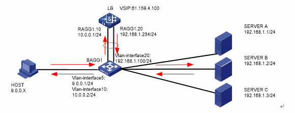
As shown in Figure 1, an external host is connected to the internal servers through an LB device. Server A, Server B, and Server C are internal servers that can provide FTP services. Configure application load balancing to enable the host to access FTP services and monitor reachability of the servers through health monitoring.
Figure 1 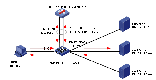 Network diagram
Analysis
To implement SNAT–based application load balancing, complete the following configuration on the LB device:
· Configure server farm, real server, and virtual service settings.
· Configure SNAT address pool settings and make sure the real servers each have a route to the SNAT address pool.
Software versions used
This configuration example was created and verified on Alpha 1160P16 of L1000-AK315.
Restrictions and guidelines
When you configure SNAT-based application load balancing, follow these restrictions and guidelines:
· In the inbound direction, configure Layer 2 transparent transmission for the switch to make sure the host has a route to reach the LB device. In the outbound direction, configure Layer 3 routing for the switch to make sure the LB device has a route to reach the server. Configure next hops for routes on the switch.
· In this example, the SNAT address pool uses the same network segment as the output interface. You need to enable ARP for the SNAT address pool.
Procedures
Perform the following configuration on the LB device.
Assigning IP addresses to interfaces
Details not shown.
Creating a health monitoring template
1. Navigate to the LB > Global Configuration > Health Monitoring page.
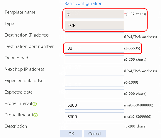
2. Click Create to create an NQA template named t1. Specify the template type as TCP and destination port number as 80.
Figure 2 Creating a health monitoring template

3. Click OK.
Creating an SNAT address pool
1. Navigate to the LB > Global Configuration > SNAT Pools page.
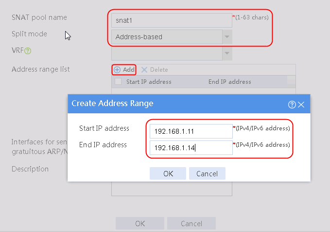
2. Click Create to create an SNAT pool named snat1. Specify start IP address 192.168.1.11 and end IP address 192.168.1.14, and configure the interfaces for sending gratuitous ARP or ND packets.
Figure 3 Creating an SNAT address pool
3. Click OK.
Figure 4 SNAT address pool information
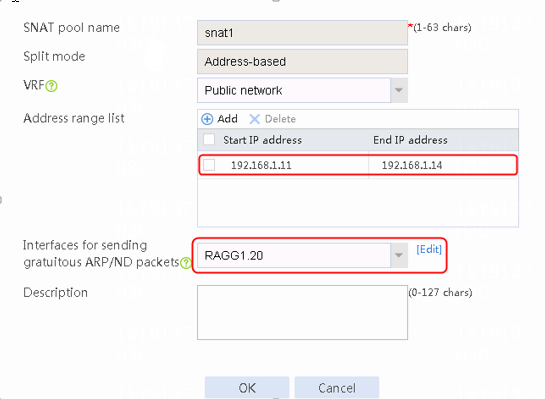
4. Click OK.
Creating a sever farm
1. Navigate to the LB > Application Load Balancing > Server Farms page.
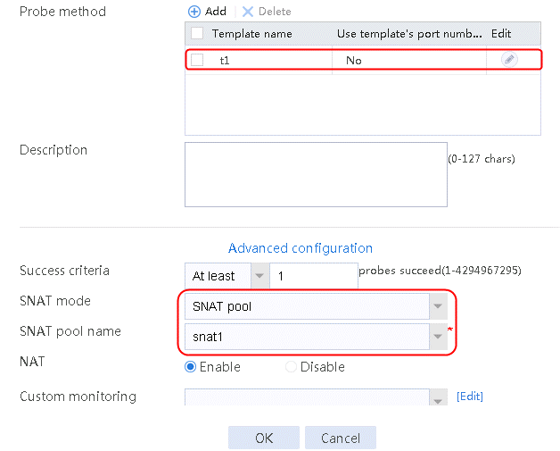
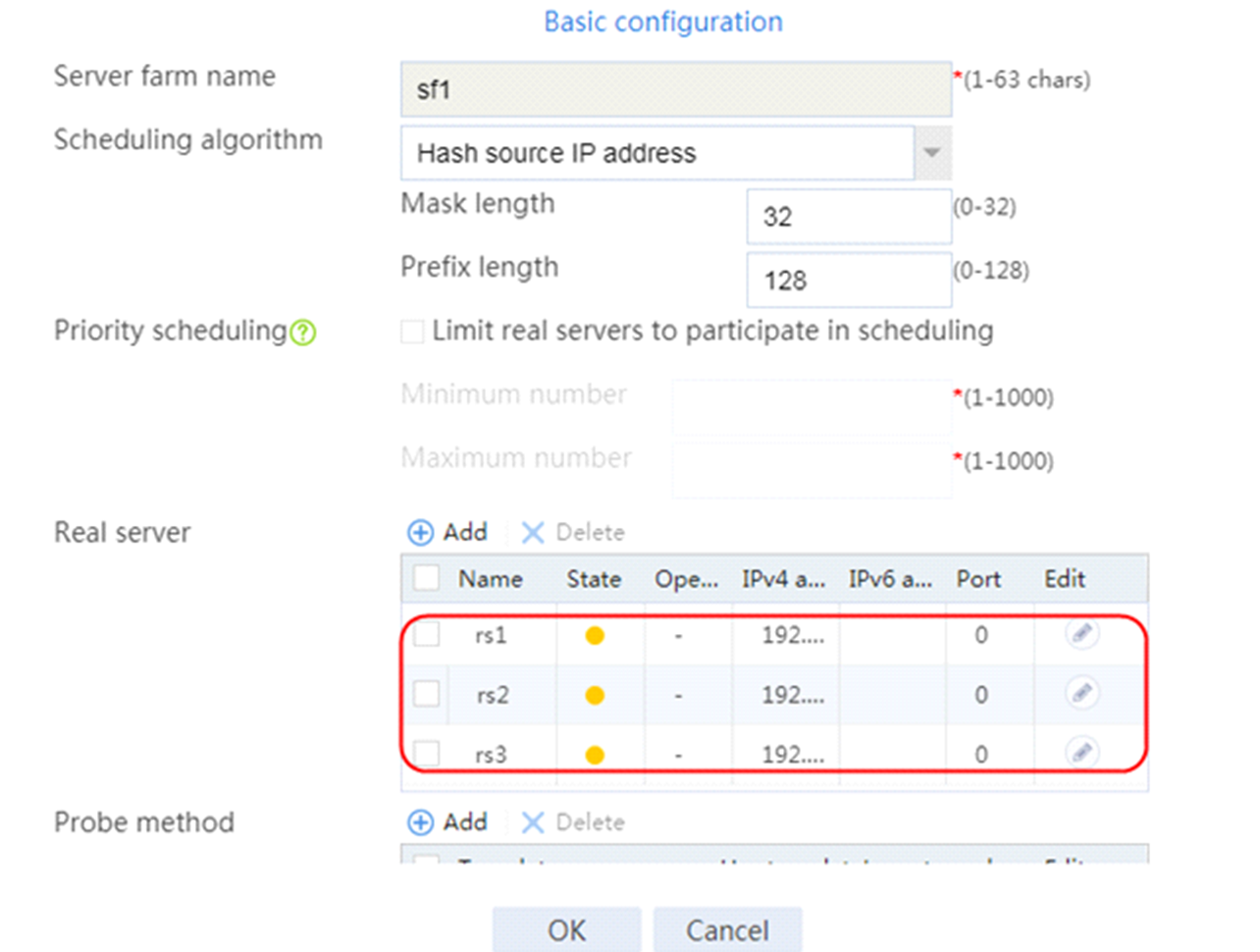
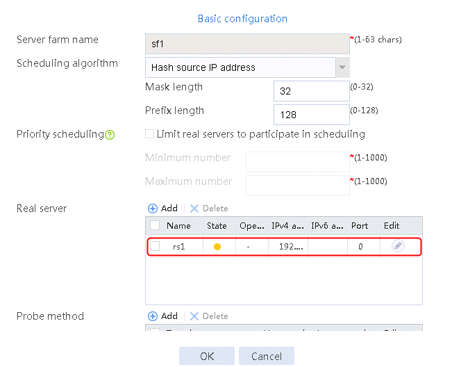
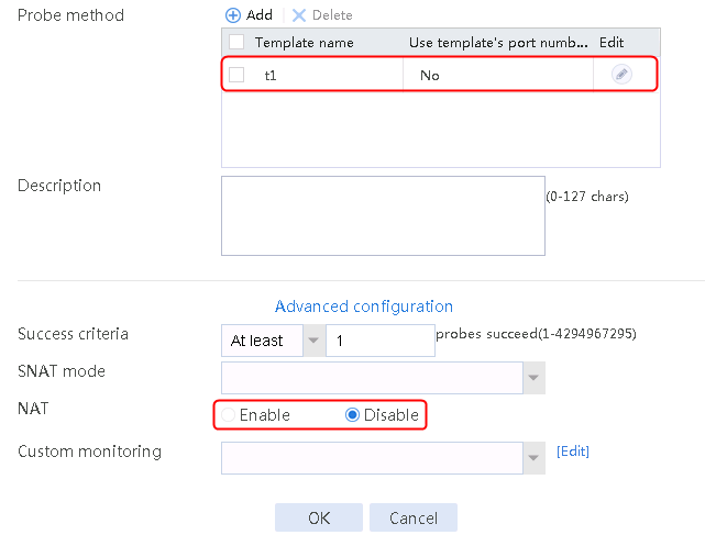
2. Click Create to create a server farm named sf1. Specify the scheduling algorithm as Hash source IP address, probe method as t1, and SNAT address pool as snat1.
Figure 5 Creating a server farm


3. Click OK.
Configuring real servers
1. Navigate to the LB > Application Load Balancing > Server Farms page.
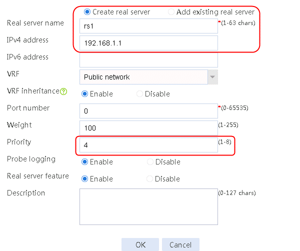
2. Edit the settings for server farm sf1. Create real server rs1 as the server farm member, and specify its IP address as 192.168.1.1.
Figure 6 Adding a server farm member

Figure 7 Creating a real server
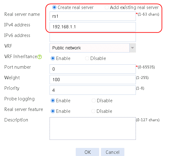
3. Click OK.
4. Create real servers rs2 and rs3 in the same way real server rs1 is created. Specify the IP address for real servers rs2 and rs3 as 192.168.1.2 and 192.168.1.3, respectively.
Figure 8 Server farm information

Configuring a virtual server
1. Navigate to the LB > Application Load Balancing > Virtual Servers page.
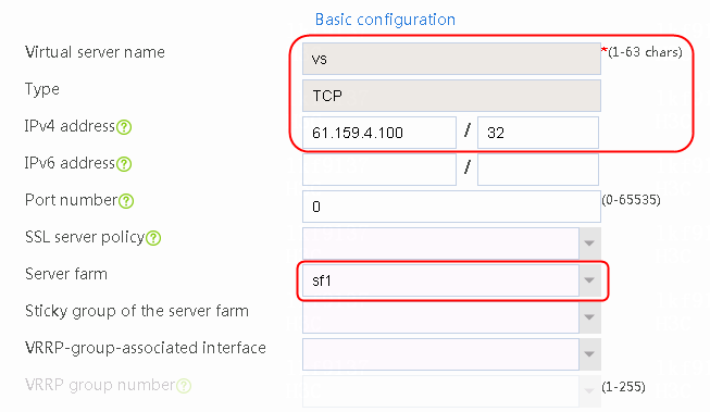
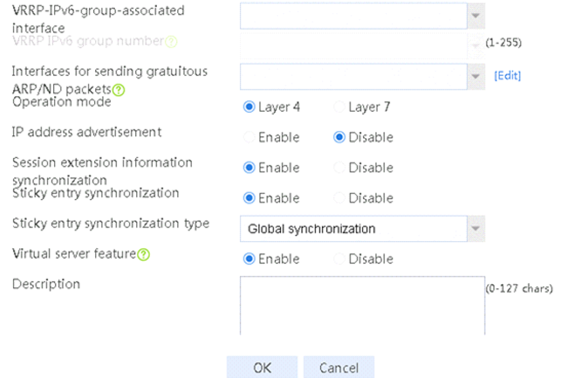
2. Click Create to create a virtual server named vs. Specify the type as TCP, IP address as 61.159.4.100, default server farm as sf1, and enable the virtual server feature.
Figure 9 Creating a virtual server


3. Click OK.
Verifying the configuration
Sending an FTP request
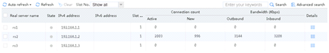
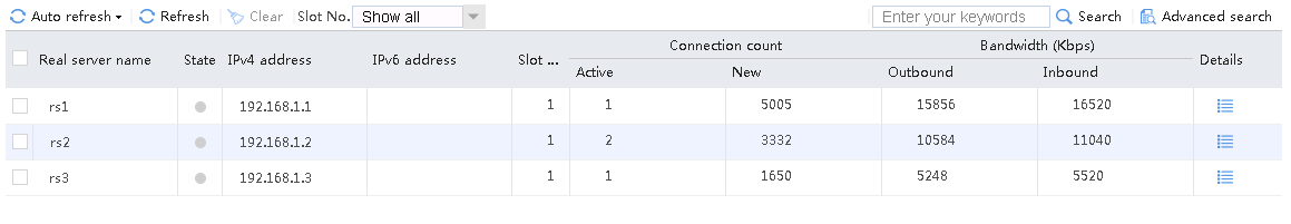
Send an FTP request from the host to the FTP server at 61.159.4.100. If the operation succeeds, you can view virtual server and real server statistics on the LB device.
Figure 10 Virtual server statistics

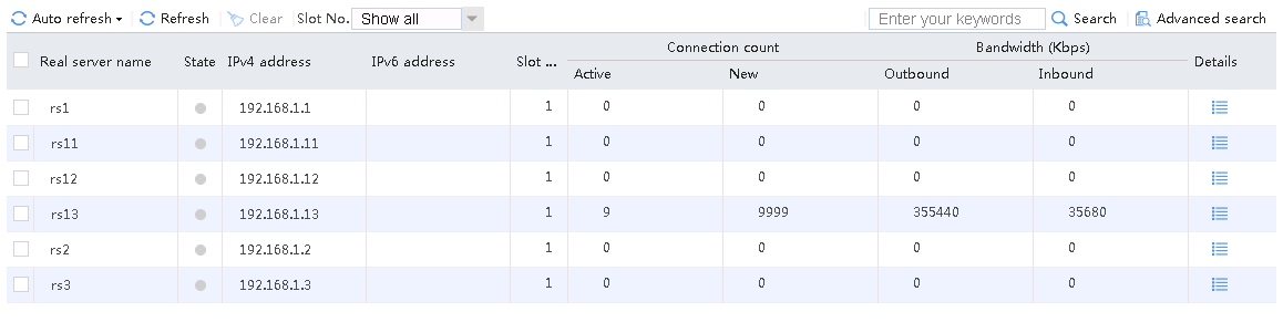
Figure 11 Real server statistics

Configuration files
#
nqa template tcp t1
destination port 80
#
server-farm sf1
predictor hash address source
snat-pool snat1
probe t1
success-criteria at-least 1
real-server rs1 port 0
success-criteria at-least 1
real-server rs2 port 0
success-criteria at-least 1
real-server rs3 port 0
success-criteria at-least 1
#
real-server rs1
ip address 192.168.1.1
#
real-server rs2
ip address 192.168.1.2
#
real-server rs3
ip address 192.168.1.3
#
loadbalance snat-pool snat1
ip range start 192.168.1.11 end 192.168.1.14
arp-nd interface Route-Aggregation1.20
#
virtual-server vs type tcp
virtual ip address 61.159.4.100
default server-farm sf1
connection-sync enable
sticky-sync enable global
service enable
#
Example: Configuring SNAT-based application load balancing (with VSIP on the same network as client IP)
Network configuration
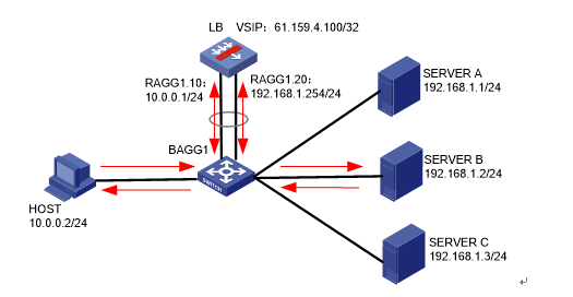
As shown in Figure 12, an external host is connected to the internal servers through an LB device. Server A, Server B, and Server C are internal servers that can provide FTP services. Configure application load balancing to enable the host to access FTP services and monitor reachability of the servers through health monitoring.

Analysis
To implement SNAT–based application load balancing, complete the following configuration on the LB device:
· Configure server farm, real server, and virtual service settings.
· Configure SNAT address pool settings and make sure the real servers each have a route to the SNAT address pool.
Software versions used
This configuration example was created and verified on Alpha 1160P16 of L1000-AK315.
Restrictions and guidelines
When you configure SNAT-based application load balancing, follow these restrictions and guidelines:
· In the inbound direction, configure Layer 2 transparent transmission for the switch to make sure the host has a route to reach the LB device. In the outbound direction, configure Layer 3 routing for the switch to make sure the LB device has a route to reach the server. Configure next hops for routes on the switch.
· In this example, the SNAT address pool uses the same network segment as the output interface. You need to enable ARP for the SNAT address pool.
· In this example, make sure the virtual server IP is in the same network segment as the outbound interface address of the client, and the IP address advertisement feature is enabled on the virtual server.
Procedures
Perform the following configuration on the LB device.
Assigning IP addresses to interfaces
Details not shown.
Creating a health monitoring template
1. Navigate to the LB > Global Configuration > Health Monitoring page.
2. Click Create to create an NQA template named t1. Specify the template type as TCP and destination port number as 80.
Figure 13 Creating a health monitoring template

3. Click OK.
Creating an SNAT address pool
1. Navigate to the LB > Global Configuration > SNAT Pools page.
2. Click Create to create an SNAT pool named snat1. Specify the start IP address as 192.168.1.11, and the end IP address as 192.168.1.14. Specify the interface for sending gratuitous ARP or ND packets.
Figure 14 Creating an SNAT pool

3. Click OK.
Figure 15 SNAT pool information

4. Click OK.
Creating a sever farm
1. Navigate to the LB > Application Load Balancing > Server Farms page.
2. Click Create to create a server farm named sf1. Specify the scheduling algorithm as Hash source IP address, probe method as t1, and SNAT address pool as snat1.
Figure 16 Creating a server farm

3. Click OK.
Configuring real servers
1. Navigate to the LB > Application Load Balancing > Server Farms page.
2. Edit the settings for server farm sf1. Create real server rs1 as the server farm member, and specify its IP address as 192.168.1.1.
Figure 17 Adding a real server

Figure 18 Creating a real server

3. Click OK.
4. Create real servers rs2 and rs3 in the same way real server rs1 is created. Specify the IP address for real servers rs2 and rs3 as 192.168.1.2 and 192.168.1.3, respectively.
Figure 19 Server farm information
Configuring a virtual server
1. Navigate to the LB > Application Load Balancing > Virtual Servers page.
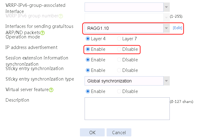
2. Click Create to create a virtual server named vs. Specify the type as TCP, virtual server IP address as 10.0.0.8, and default server farm as sf1. Enable the IP address advertisement and virtual server features.
Figure 20 Creating a virtual server
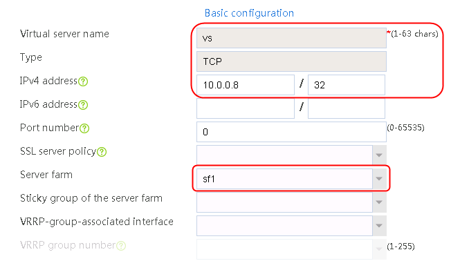
3. Click OK.
Verifying the configuration
Sending an FTP request
Sent an FTP request from the host to the FTP server with IP address 10.0.0.8. After the access is successful, you can view the virtual server and real server statistics on the LB device.
Figure 21 Virtual server statistics
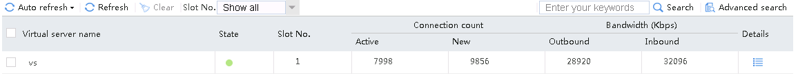
Figure 22 Real server statistics
Configuration files
#
nqa template tcp t1
destination port 80
#
server-farm sf1
predictor hash address source
snat-pool snat1
probe t1
success-criteria at-least 1
real-server rs1 port 0
success-criteria at-least 1
real-server rs2 port 0
success-criteria at-least 1
real-server rs3 port 0
success-criteria at-least 1
#
real-server rs1
ip address 192.168.1.1
#
real-server rs2
ip address 192.168.1.2
#
real-server rs3
ip address 192.168.1.3
#
loadbalance snat-pool snat1
ip range start 192.168.1.11 end 192.168.1.14
arp-nd interface Route-Aggregation1.20
#
virtual-server vs type tcp
virtual ip address 10.0.0.8
default server-farm sf1
route-advertisement enable
connection-sync enable
sticky-sync enable global
arp-nd interface Route-Aggregation1.10
service enable
#
Example: Configuring source address-based application load balancing
Network configuration
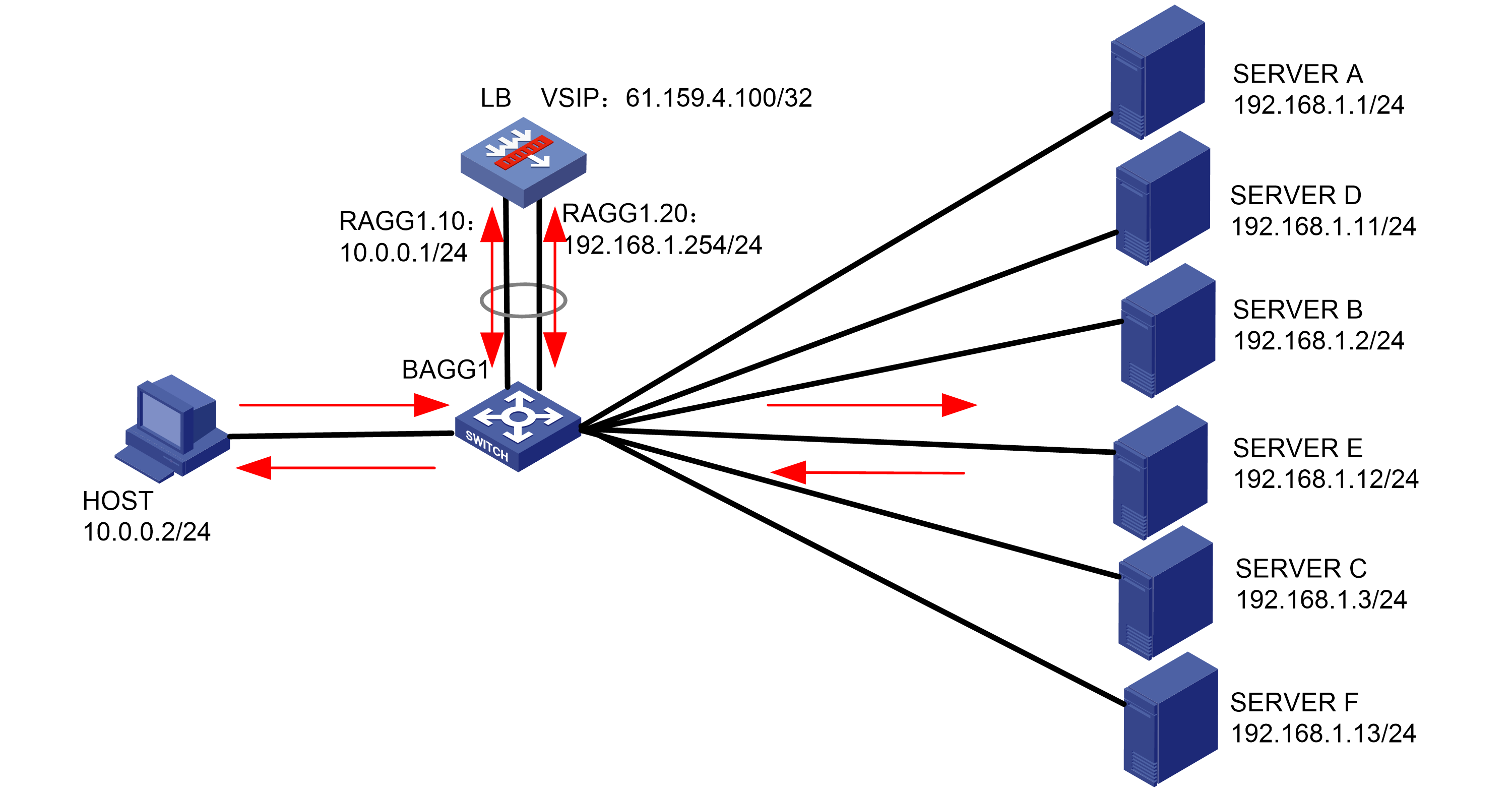
As shown in the Figure 23, the LB device connects the user and three servers Server A, Server B and Server C that can provide FTP services. Configure application load balancing to enable these servers to jointly provide FTP services and monitor reachability of the servers through health monitoring.

Analysis
To implement source address-based application load balancing, complete the following configuration on the LB device:
· Configure server farm, real server, and virtual service settings.
· Configure LB policy settings.
Software versions used
This configuration example was created and verified on Alpha 1160P16 of L1000-AK315.
Restrictions and guidelines
When you configure source address-based application load balancing, follow these restrictions and guidelines:
· Make sure the routes from the host to the LB device, from the LB device to the server, and from the server to the LB device are available, and the server gateway is deployed on the LB device.
· Configure Layer 2 transparent transmission for both inbound and outbound directions on the switch, with the gateway on the LB device.
Procedures
Perform the following configuration on the LB device.
Assigning IP addresses to interfaces
Details not shown.
Creating a health monitoring template
1. Navigate to the LB > Global Configuration > Health Monitoring page.
2. Click Create to create an NQA template named t1. Specify the template type as TCP and destination port number as 80.
Figure 24 Creating a health monitoring template

3. Click OK.
Creating server farms
1. Navigate to the LB > Application Load Balancing > Server Farms page.
2. Click Create to create a server farm named sf1. Specify the scheduling algorithm as Hash source IP address and probe method as t1.
Figure 25 Creating a server farm


3. Click OK.
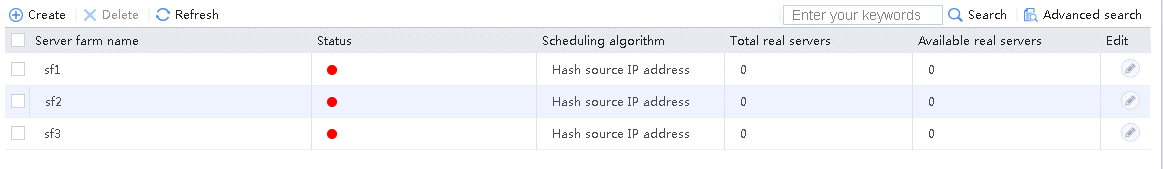
4. Create server farms sf2 and sf3 in the same way sf1 is created.
Figure 26 Server farm information

Configuring real servers
1. Navigate to the LB > Application Load Balancing > Server Farms page.
2. Edit the settings for server farm sf1. Create real server rs1 as the server farm member, and specify its IP address as 192.168.1.1.
Figure 27 Adding a real server

Figure 28 Creating a real server

3. Click OK.
Figure 29 Real server information
4. Click OK.
5. Create real server rs2 in the same way rs1 is created:
a. Navigate to the LB > Application Load Balancing > Server Farms page.
b. Edit server farm sf2 to add a real server.
c. Create real server rs2 as shown in the figure above, and configure its IPv4 address as 192.168.1.2.
6. Create real server rs3 in the same way rs1 is created:
a. Navigate to the LB > Application Load Balancing > Server Farms page.
b. Edit server farm sf3 to add a real server.
c. Create real server rs3 as shown in the figure above, and configure its IPv4 address as 192.168.1.3.
Configuring LB classes
1. Navigate to the LB > Application Load Balancing > Advanced Policies > Class page.
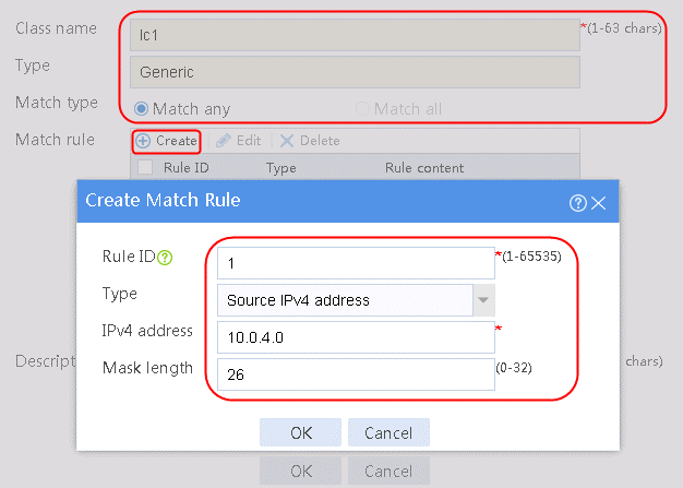
2. Click Create to create a class named lc1, and set the type to Generic and the match type to Match any. In the Create Match Rule dialog box, set the rule ID to 1, the type to Source IPv4 address, the IPv4 address to 10.0.4.0, and the mask length to 26. Then click OK.
Figure 30 Creating a class
3. Click OK.
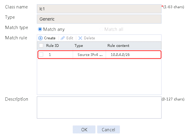
Figure 31 Class information
4. Click OK.
5. Create lc2 in the same way lc1 is created. Specify IPv4 address 10.0.4.64 and mask length 26 in the match rule of lc2.
Configuring LB actions
1. Navigate to the LB > Application Load Balancing > Advanced Policies > Action page.
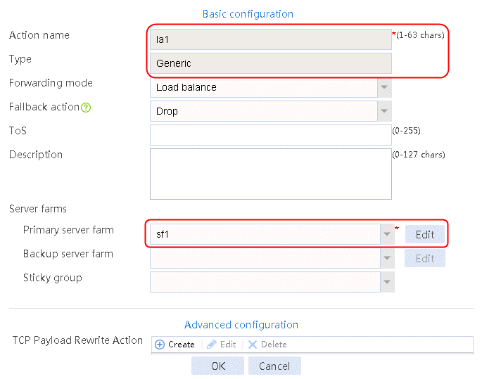
2. Click Create to create an action named la1, specify the type as Generic, and the primary server farm as sf1.
Figure 32 Creating an action
3. Click OK.
4. Create la2 and la3 in the same way la1 is created. The primary server farm of la2 is sf2, and the primary server farm of la3 is sf3.
Configuring an LB policy
1. Navigate to the LB > Application Load Balancing > Advanced Policies > Load Balancing Policy page.
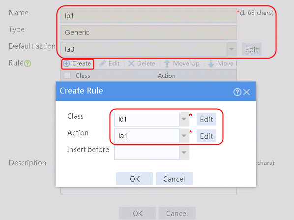
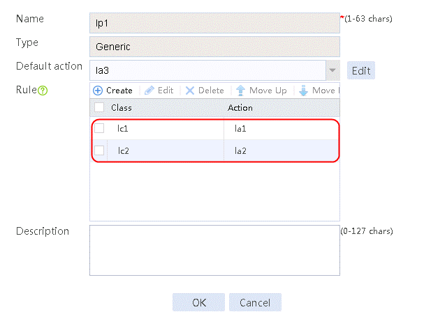
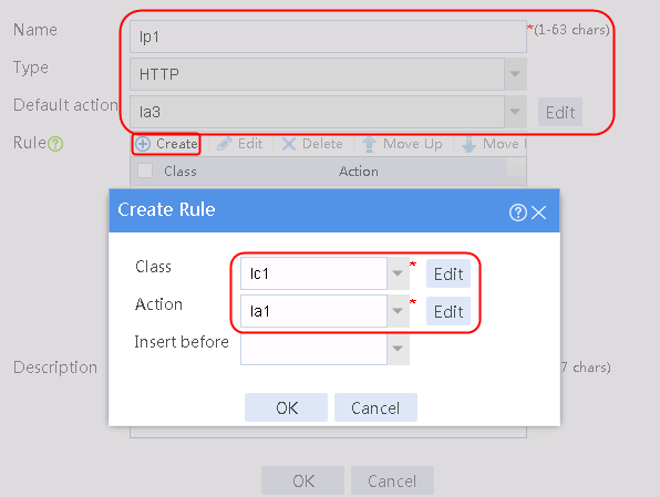
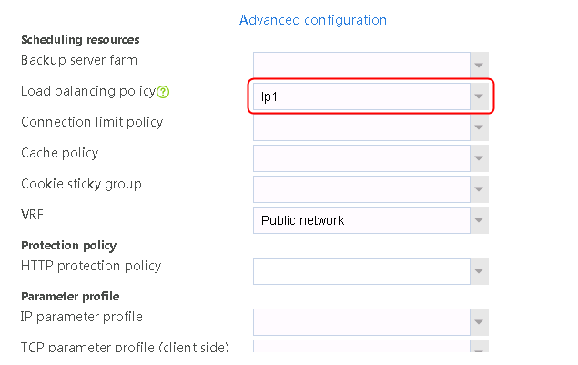
2. Click Create to create a policy named lp1, specify the type as Generic, and specify the default action as la3.
3. Click Create to create a rule. Specify the class as lc1, and the action as la1, and then click OK.
4. Click Create to create another rule. Specify the class as lc2, and the action as la2, and then click OK. .
Figure 33 Creating policy lp1
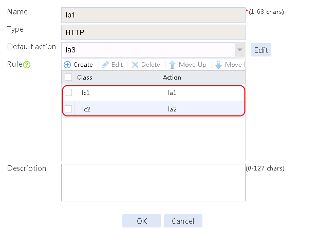
5. Click OK.
Figure 34 Policy lp1 configuration information
6. Click OK.
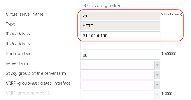
Creating virtual server vs
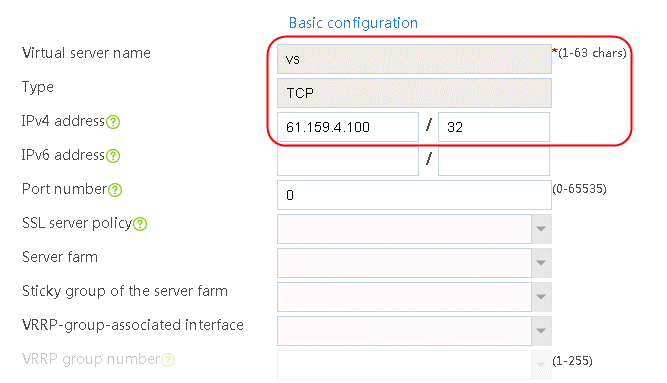
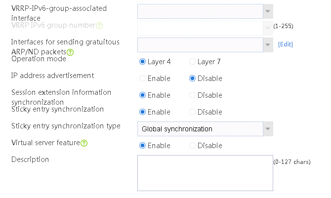
1. Navigate to the LB > Application Load Balancing > Virtual Servers page.
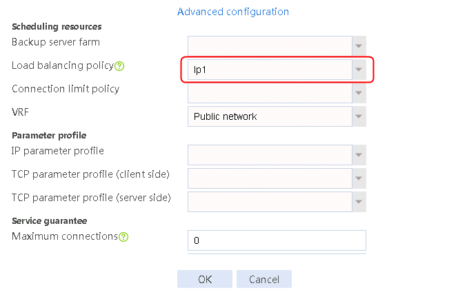
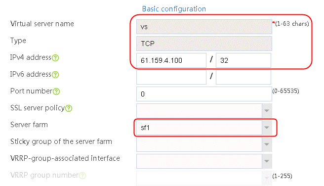
2. Click Create to create a virtual server named vs. Specify the type as TCP, the IPv4 address as 61.159.4.100/32, the load balancing policy as lp1, and enable the virtual server feature.
Figure 35 Creating a virtual server
3. Click OK.
Verifying the configuration
Sending FTP requests
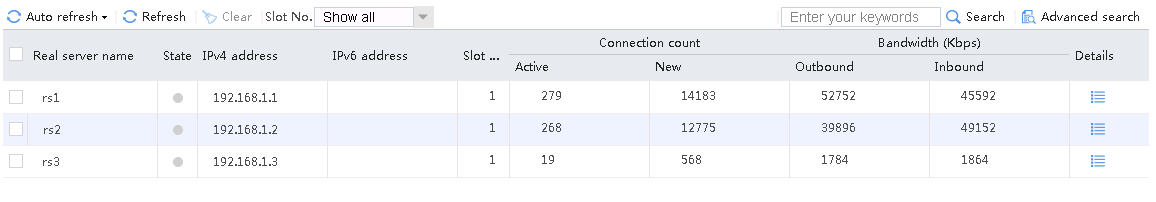
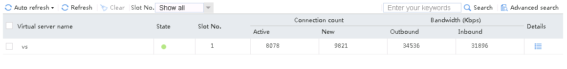
Send three FTP requests from the host with source addresses 10.0.4.1, 10.0.4.65, and 10.0.4.129, respectively. After accessing the FTP server through the virtual server with IP address 61.159.4.100 successfully, you can view the virtual server and real server statistics. The FTP requests from source addresses 10.0.4.64/26 and 10.0.4.64/26 are assigned to rs1 and rs2, respectively. The FTP requests from other source addresses are assigned to rs3.
Figure 36 Viewing virtual server statistics

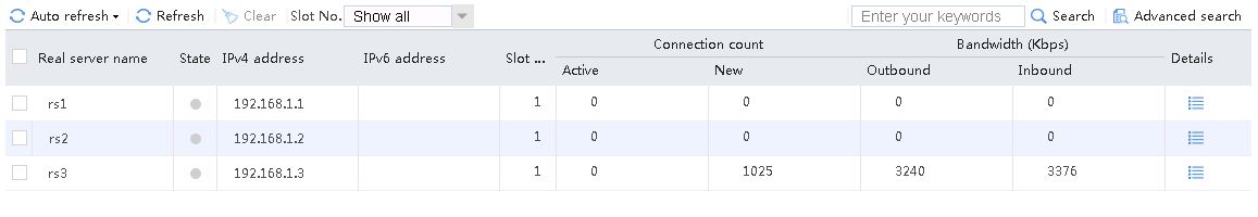
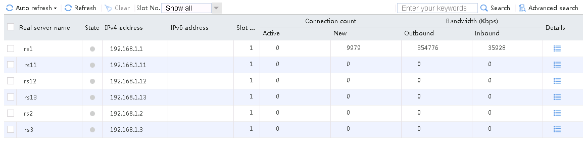
An FTP request sourced from 10.0.4.1 matches policy lc1 and is sent to rs1. You can view the real server statistics of only rs1.
Figure 37 Viewing real server statistics

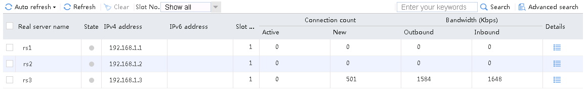
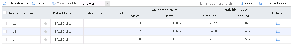
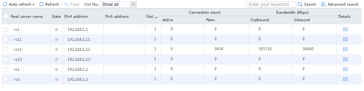
An FTP request sourced from 10.0.4.65 matches policy lc2 and is sent to rs2. You can view the real server statistics of only rs2.
Figure 38 Viewing real server statistics

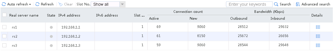
An FTP request sourced from 10.0.4.129 matches policy lc3 and is sent to rs3. You can view the real server statistics of only rs3.
Figure 39 Viewing real server statistics

Configuration files
#
nqa template tcp t1
destination port 80
#
server-farm sf1
predictor hash address source
probe t1
success-criteria at-least 1
real-server rs1 port 0
success-criteria at-least 1
#
server-farm sf2
predictor hash address source
probe t1
success-criteria at-least 1
real-server rs2 port 0
success-criteria at-least 1
#
server-farm sf3
predictor hash address source
probe t1
success-criteria at-least 1
real-server rs3 port 0
success-criteria at-least 1
#
real-server rs1
ip address 192.168.1.1
#
real-server rs2
ip address 192.168.1.2
#
real-server rs3
ip address 192.168.1.3
#
loadbalance class lc1 type generic match-any
match 1 source ip address 10.0.4.0 26
#
loadbalance class lc2 type generic match-any
match 1 source ip address 10.0.4.64 26
#
loadbalance action la1 type generic
server-farm sf1
#
loadbalance action la2 type generic
server-farm sf2
#
loadbalance action la3 type generic
server-farm sf3
#
loadbalance policy lp1 type generic
class lc1 action la1
class lc2 action la2
default-class action la3
#
virtual-server vs type tcp
virtual ip address 61.159.4.100
lb-policy lp1
connection-sync enable
sticky-sync enable global
service enable
#
Example: Configuring triangle transmission
Network configuration
As shown in the Figure 40, the three servers Server A, Server B and Server C can provide FTP services.
The network requirements are as follows:
· User requests accessing the virtual server address are forwarded through the LB device to the real servers.
· Response packets are forwarded through the switch directly to reduce workload on the LB device.
To implement these requirements, configure application load balancing as follows:
· Specify the source IP address of response packets for the servers as the IP address of the virtual server.
· Enable the three servers to jointly provide FTP services by considering their hardware performance.
· Monitor the state of the servers through health monitoring.
Analysis
To implement triangle transmission, complete the following configuration on the LB device:
· Configure server farm, real server, and virtual service settings.
· To forward server response packets directly through the switch, specify the source address of the response packets as the IP address of the virtual server. Therefore, in addition to physical interface addresses, you need to configure loopback interfaces for the real servers and specify the loopback interface address as the virtual server IP address 61.159.4.100.
Software versions used
This configuration example was created and verified on Alpha 1160P16 of L1000-AK315.
Restrictions and guidelines
When you configure triangle transmission, follow these restrictions and guidelines:
· Make sure the switch has Layer 3 routing capabilities in the inbound direction, and the inbound gateway is on the switch. The direct routes from the host to the switch and from the switch to the LB device are available. The route from the host to the LB device is available, with the switch as the next hop. Make sure the switch has Layer 3 routing capabilities in the outbound direction. The routes from the LB device to the server and from the server to the host are available, both with the switch as the next hop.
· The request packets are forwarded through the LB device, but the response packets are not forwarded through the LB device. Make sure the route from the server back to the host is available.
· Disable the DNAT feature in the server farm.
Procedures
Perform the following configuration on the LB device.
Assigning IP addresses to interfaces
Details not shown.
Creating a health monitoring template
1. Navigate to the LB > Global Configuration > Health Monitoring page.
2. Click Create to create an NQA template named t1. Specify the template type as TCP and destination port number as 80.
Figure 41 Creating a health monitoring template
3. Click OK.
Creating a sever farm
1. Navigate to the LB > Application Load Balancing > Server Farms page.
2. Click Create to create a server farm named sf1. Specify the scheduling algorithm as Hash source IP address and probe method as t1, and disable the NAT feature.
Figure 42 Creating a server farm

3. Click OK.
Configuring real servers
1. Navigate to the LB > Application Load Balancing > Server Farms page.
2. Edit the settings for server farm sf1. Create real server rs1 as the server farm member, and specify its IP address as 192.168.1.1.
Figure 43 Adding a real server

Figure 44 Creating a real server

3. Click OK.
4. Create real servers rs2 and rs3 in the same way real server rs1 is created. Specify the IP address for real servers rs2 and rs3 as 192.168.1.2 and 192.168.1.3, respectively.
Figure 45 Server farm information

Creating a virtual server
1. Navigate to the LB > Application Load Balancing > Virtual Servers page.
2. Click Create to create a virtual server named vs, specify the type as TCP, virtual server IP address as 61.159.4.100/32, and default server farm as sf1, and enable the virtual server feature.
Figure 46 Creating a virtual server
3. Click OK.
Verifying the configuration
Sending an FTP request
Send an FTP request from the host to the FTP server with IP address 61.159.4.100. After the access is successful, you can view the virtual server and real server statistics on the LB device.
Figure 47 Virtual server statistics

Figure 48 Real server statistics

Configuration files
#
nqa template tcp t1
destination port 80
#
server-farm sf1
predictor hash address source
transparent enable
probe t1
success-criteria at-least 1
real-server rs1 port 0
success-criteria at-least 1
real-server rs2 port 0
success-criteria at-least 1
real-server rs3 port 0
success-criteria at-least 1
#
real-server rs1
ip address 192.168.1.1
#
real-server rs2
ip address 192.168.1.2
#
real-server rs3
ip address 192.168.1.3
#
virtual-server vs type tcp
virtual ip address 61.159.4.100
default server-farm sf1
connection-sync enable
sticky-sync enable global
service enable
#
Example: Configuring priority scheduling-based application load balancing
Network configuration
As shown in the Figure 49, the external user accesses the internal server through the LB device. Three servers Server A, Server B and Server C can provide FTP services. The LB device distributes user requests based on the server priorities and the number of real servers allowed to be scheduled in the server farm to achieve load balancing.

Analysis
To implement priority scheduling-based application load balancing, complete the following configuration on the LB device:
· Configure server farm, real server, and virtual service settings.
· To distribute traffic to only the server with the highest priority, set the number of real servers available for scheduling in the server farm to 1, and set the priorities for the real servers to 4, 8, and 1, respectively.
· To distribute traffic to two servers, set the number of real servers available for scheduling in the server farm to 2, and set the priorities for the real servers to 4, 8, and 1, respectively.
Software versions used
This configuration example was created and verified on Alpha 1160P16 of L1000-AK315.
Restrictions and guidelines
When you configure priority scheduling-based application load balancing, follow these restrictions and guidelines:
· Makes sure the routes from the host to the LB device, from the LB device to the server, and from the server to the LB device are available, with the LB device as the gateway.
· Configure Layer 2 transparent transmission in both the inbound and outbound directions of the switch, with the LB device as the gateway.
· Configure the number of real servers available for scheduling in the server farm, and set different priorities for the real servers.
Procedures
Perform the following configuration on the LB device.
Assigning IP addresses to interfaces
Details not shown.
Creating a health monitoring template
1. Navigate to the LB > Global Configuration > Health Monitoring page.
2. Click Create to create an NQA template named t1. Specify the template type as TCP and destination port number as 80.
Figure 50 Creating a health monitoring template

3. Click OK.
Creating a server farm
1. Navigate to the LB > Application Load Balancing > Server Farms page.
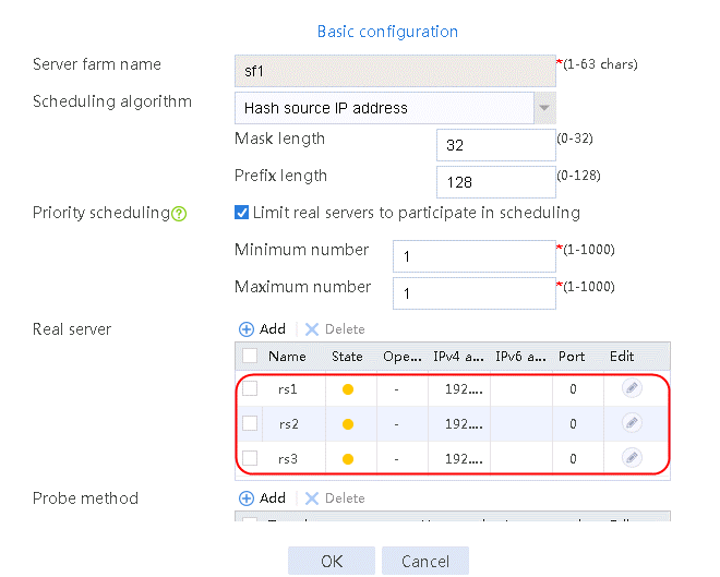
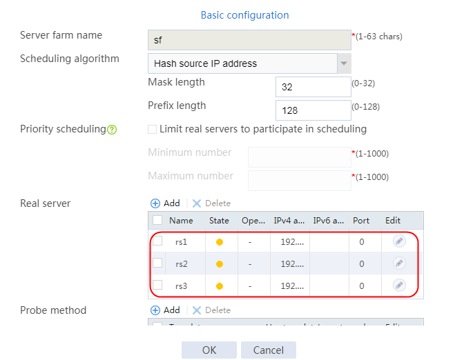
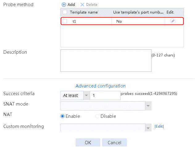
2. Click Create to create a server farm named sf1. Specify the scheduling algorithm as Hash source IP address and probe method as t1. Select the Limit real servers to participate in scheduling option, and set both minimum number and maximum number to 1.
Figure 51 Creating a server farm


3. Click OK.
Configuring real servers
1. Navigate to the LB > Application Load Balancing > Server Farms page.
2. Edit server farm sf1. Add real server rs1, and specify its IP address as 192.168.1.1 and priority as 4.
Figure 52 Adding a real server

Figure 53 Creating a real server
3. Click OK.
4. Create real servers rs2 and rs3 in the same way rs1 is created. Set the priority of rs2 to 8, and the IPv4 address to 192.168.1.2. Set the priority of rs3 to 1, and the IPv4 address to 192.168.1.3.
Figure 54 Server farm information
Configuring a virtual server
1. Navigate to the LB > Application Load Balancing > Virtual Servers page.
2. Click Create to create a virtual server named vs. Specify the type as TCP, IP address as 61.159.4.100, default server farm as sf1, and enable the virtual server feature.
Figure 55 Creating a virtual server
3. Click OK.
Verifying the configuration
Sending an FTP request
When number of servers available for scheduling is set to 1, send an FTP request from the host to the FTP server with IP address 61.159.4.100. After the access is successful, you can view the virtual server and real server statistics on the LB device. Real server rs2 with the highest priority is selected, and only real server rs2 has traffic statistics.
Figure 56 Virtual server statistics
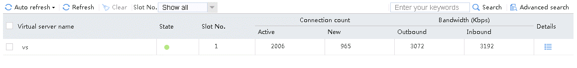
Figure 57 Real server statistics
When number of servers available for scheduling is set to 2, send an FTP request from the host to the FTP server with IP address 61.159.4.100. After the access is successful, you can view the virtual server and real server statistics on the LB device. The traffic is distributed to rs1 and rs2 with higher priorities.
Figure 58 Virtual server statistics

Figure 59 Real server statistics

Configuration files
#
nqa template tcp t1
destination port 80
#
server-farm sf1
predictor hash address source
selected-server min 1 max 1
probe t1
success-criteria at-least 1
real-server rs1 port 0
success-criteria at-least 1
real-server rs2 port 0
priority 8
success-criteria at-least 1
real-server rs3 port 0
priority 1
success-criteria at-least 1
#
real-server rs1
ip address 192.168.1.1
#
real-server rs2
ip address 192.168.1.2
#
real-server rs3
ip address 192.168.1.3
#
virtual-server vs type tcp
virtual ip address 61.159.4.100
default server-farm sf1
connection-sync enable
sticky-sync enable global
service enable
#
Example: Configuring Layer 4 application load balancing for high availability
Network configuration
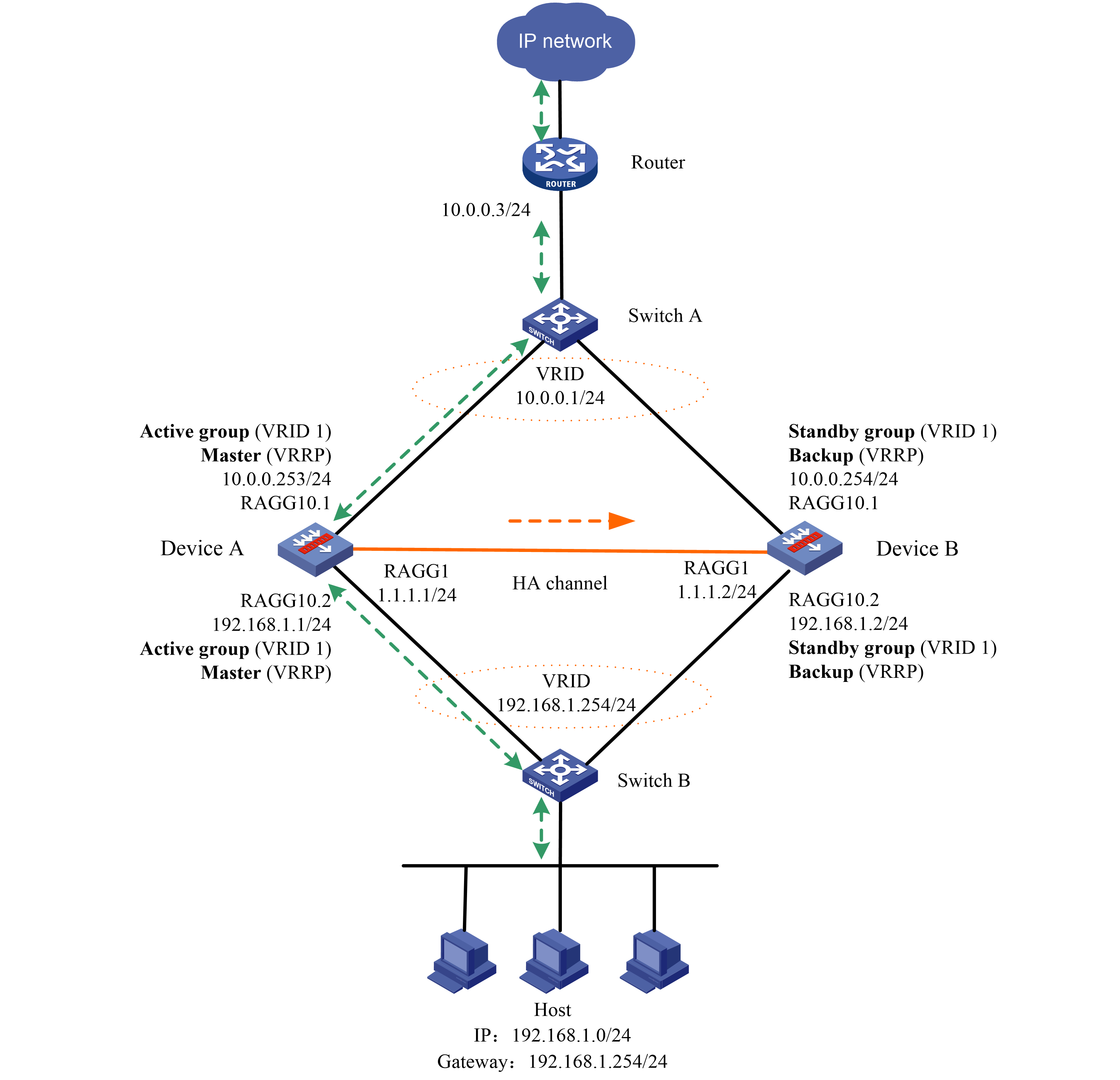
To improve service stability, configure two LB devices in a network deployed with HA group and VRRP, with Device A as the master and Device B as the backup. When Device A or the associated links fail, Device B takes over to ensure service continuity (the service traffic is not automatically switched back by default).
Figure 60 Network diagram
Analysis
To implement service switchover when one of the two LB devices fails, complete the following configuration:
· Configure and issue interface addresses and VRRP settings to both LB devices, configure VRRP group settings on the associated interfaces, and configure the virtual IP address of the VRRP group.
· Configure and issue HA group settings on both LB devices, and set up the HA control and data channels on the directly connected interfaces as aggregate interfaces between the two devices. Specify the primary and secondary devices for the HA group, specify the control channel and data channel, and enable the automatic backup and hot backup of configuration.
· Configure and issue basic configurations that dot not require backup, such as routing and health monitoring, on the two devices.
Software versions used
This configuration example was created and verified on Feature 1160P16 of L1050.
Restrictions and guidelines
When you configure Layer 4 application load balancing for high availability, follow these restrictions and guidelines:
· When deleting and modifying the LB service configuration that can be backed up, perform the operation on the primary device of the HA group and synchronize the configuration to the secondary device. Do not modify or delete configuration on the secondary device to prevent configuration inconsistency on the two devices. The existing load balancing configuration on the primary device will be backed up in batches after automatic configuration synchronization is enabled. You can also manually synchronize the configuration to the secondary device. For routing and probe method settings that do not require backup but must be consistent on both devices, configure and issue the settings to the devices separately.
· You must configure the NQA probe method template, interface IP address, routing and other related settings manually on both the primary and secondary devices and saved them as basic configuration. For files such as ISP files for load balancing, certificate files related to SSL offloading, and script files for custom monitoring, import, issue, and save them on the devices separately.
· In the current software version, configuration synchronization is supported by the following service modules:
¡ Resources—VPN instance, ACL (except the acl copy command), object group, time range, security zone, session management, APR, and AAA.
¡ DPI related modules—Application layer detection engine, IPS, URL filtering, data filtering, file filtering, antivirus, data analysis center, and WAF.
¡ Policies—Security policy, ASPF, attack detection and prevention (except the blacklist ip command), connection limit, NAT, AFT, load balancing, bandwidth management, application audit and management, shared access management, and proxy policy.
¡ Logs—Fast log output (except the customlog host source command), and flow log (except the userlog flow export source-ip command).
¡ VPN—SSL VPN.
¡ Other types—VLAN and information center (except the info-center loghost source command).
· As a best practice, use static aggregation the for data and control channels of the HA group.
· Save the basic configuration and service configuration after they are completed.
· In the HA group and VRRP collaborated network, when the master device fails, the traffic is automatically switched to the peer device for processing. By default, when the original active device recovers, traffic is not switched back. To address this issue, enable preemption and set the switchover delay to ensure that the service can be switched back smoothly. A switchover delay timer of 0 means that service cannot be switched back.
· The SNAT address pool configuration for load balancing is based on address splitting. When the address in the SNAT address pool is on the same network segment as the IP address of the interface where the device connects to the server, specify the interface that sends gratuitous ARP or ND packets for the SNAT address pool. You must specify the interface on the device connecting to the server. When they are not on the same network segment, you do not need to specify an interface for sending gratuitous ARP or ND packets for the SNAT address pool.
· When the virtual server IP address is on the same network as the IP address of the interface where the device connects to the client, you must specify the interface that sends gratuitous ARP or ND packets for the virtual server. Make sure the interface belongs to the device connecting to the client. When they are not on the same network segment, you do not need to specify an interface for sending gratuitous ARP or ND packets for the virtual server.
· Bind the virtual server to the VRRP group for load balancing. If both IPv4 and IPv6 addresses exist, bind each of them to the VRRP group.
Procedures
Perform the following configuration on the LB device.
Assigning IP addresses to interfaces
Details not shown.
Configuring HA group settings on the active device
1. Navigate to the System > HA > HA page.
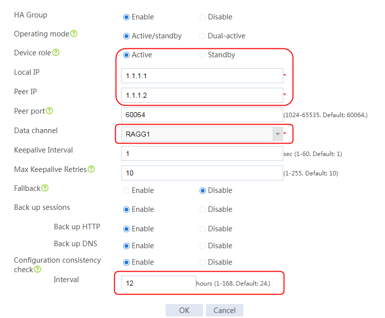
2. Click Configure. On the HA group configuration page, enable HA group, specify the operating mode as Active/standby, and specify the device role as Active. Specify the local address as 1.1.1.1, and the peer IP address as 1.1.1.2. Specify the data channel as RAGG1, enable configuration consistency check, and set the time interval to 12 hours.
Figure 61 Configuring HA group settings
3. Click OK.
Configuring VRRP settings on the active device
1. Navigate to the System > HA > VRRP page.
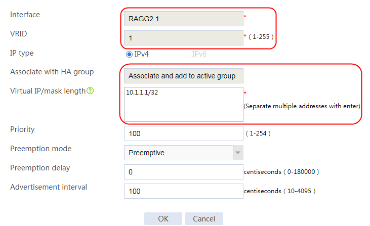
2. Click Create. Specify the interface where the VRRP group resides as the Layer 3 aggregation subinterface 2.1 and the VRID as 1, select Associate and add to active group, and set the virtual IP address to 10.1.1.1/32.
Figure 62 Configuring VRRP group settings
3. Click OK.
4. Create Layer 3 aggregate subinterface 2.2 where the VRRP group resides in the same way Layer 3 aggregate subinterface 2.1 is created.
Navigate to the System > HA > VRRP page to add a VRRP backup. Specify the interface where the VRRP group resides as the Layer 3 aggregation subinterface 2.2 and the VRID as 1, select Associate and add to VRRP active group, and set the virtual IP address to 192.168.1.254/32.
Configuring HA group settings on the standby device
1. Navigate to the System > HA > HA page.
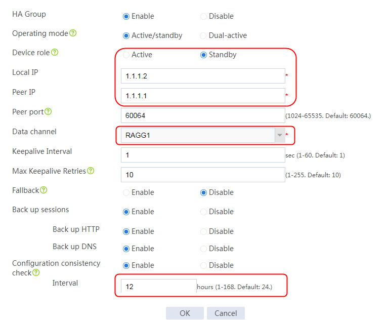
2. Click Configure. On the HA group configuration page, enable HA group, specify the operating mode as Active/standby, and specify the device role as Standby. Specify the local address as 1.1.1.2, and the peer IP address as 1.1.1.1. Specify the data channel as RAGG1, enable configuration consistency check, and set the time interval to 12 hours.
Figure 63 Configuring HA group settings
3. Click OK.
Configuring VRRP settings on the standby device
1. Navigate to the System > HA > VRRP page.
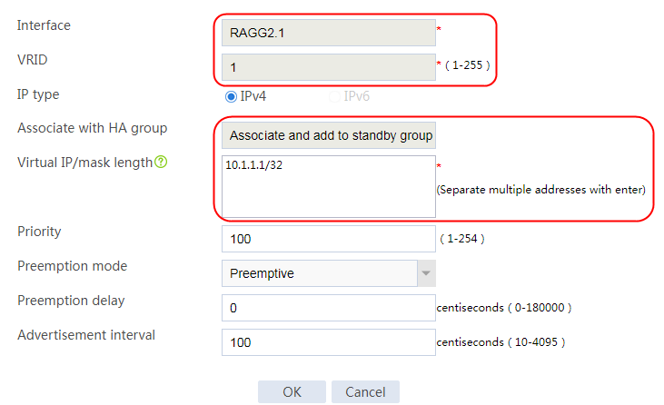
2. Click Create. Specify the interface where the VRRP group resides as the Layer 3 aggregation subinterface 2.1 and the VRID as 1, select Associate and add to standby group, and set the virtual IP address to 10.1.1.1/32.
Figure 64 Configuring VRRP backup group
3. Click OK.
4. Create Layer 3 aggregate subinterface 2.2 where the VRRP group resides in the same way Layer 3 aggregate subinterface 2.1 is created.
Navigate to the System > HA > VRRP page to add a VRRP backup. Specify the interface where the VRRP group resides as the Layer 3 aggregation subinterface 2.2 and the VRID as 1, select Associate and add to VRRP standby group, and set the virtual IP address to 192.168.1.254/32.
Configuring a health monitoring template
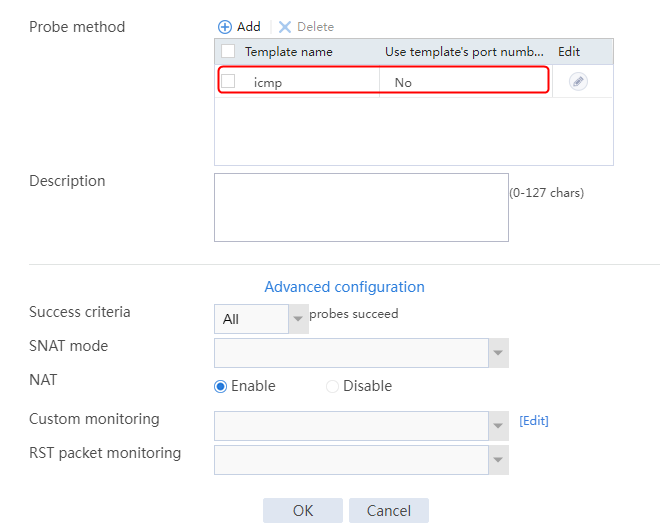
1. Navigate to the LB > Global Configuration > Health Monitoring page.
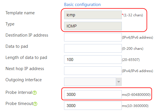
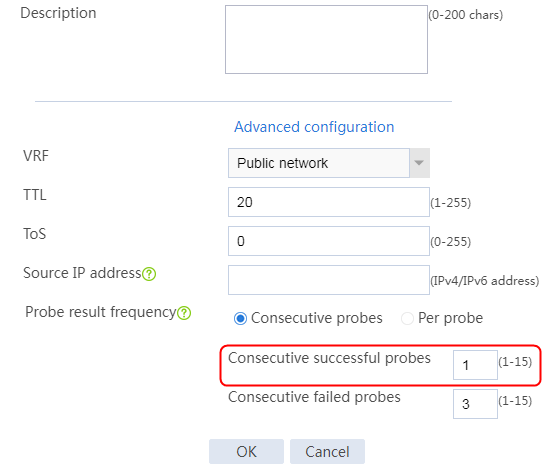
2. Click Create to create a health monitoring template named icmp. Specify the type as ICMP, probe interval as 3000 ms, and the number of successful consecutive probes as 1. The NQA health monitoring template does not require backup, so you need to configure it on both devices.
Figure 65 Adding a health monitoring template
3. Click OK.
Configuring an SNAT pool
1. Navigate to the LB > Global Configuration > SNAT Pool page.
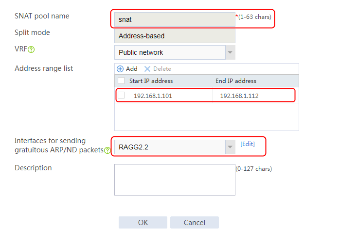
2. Click Create to create an SNAT pool snat, configure the address range from 192.168.1.101 to 192.168.1.112, and configure the interface for sending gratuitous ARP or ND packets.
Figure 66 Adding an SNAT pool
Configuring a server farm
1. Navigate to the LB > Application Load Balancing > Server Farms page.
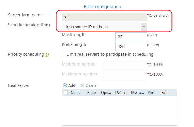
2. Click Create to create a server farm named sf1. Specify the scheduling algorithm as Hash source IP address and probe method as icmp.
Figure 67 Adding the server farm
3. Click OK.
Configuring real servers
1. Navigate to the LB > Application Load Balancing > Server Farms page.
2. Edit server farm sf. Add a new real server named rs1, and specify the real server IP address as 192.168.1.101.
Figure 68 Adding a real server
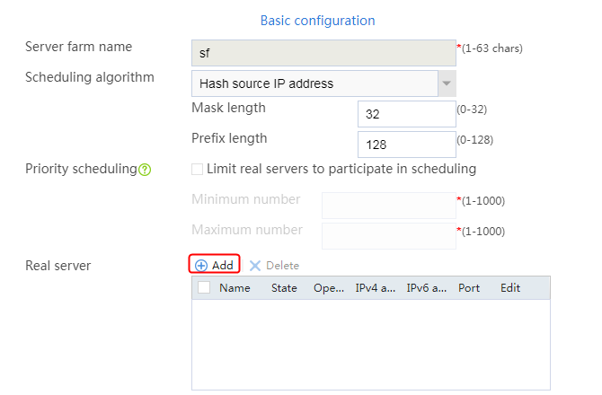
Figure 69 Adding a real server
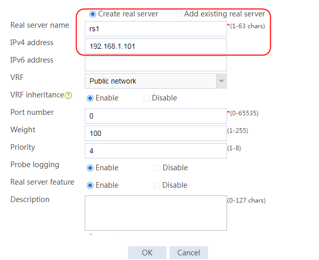
3. Click OK.
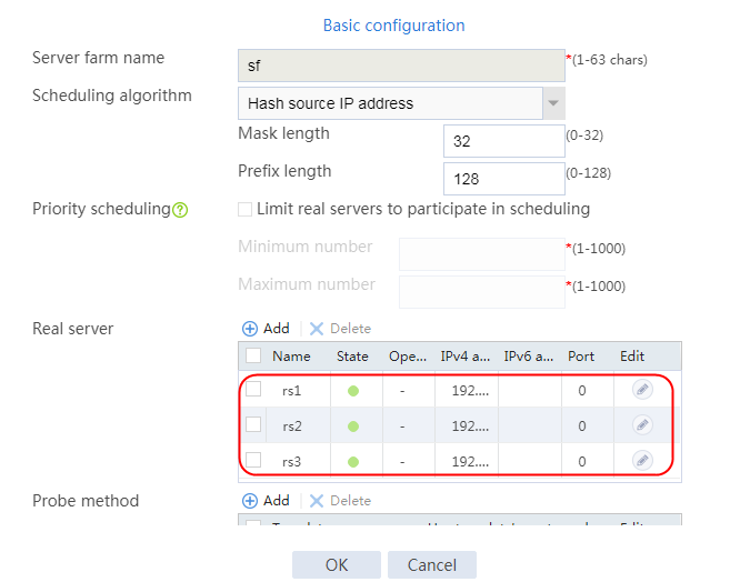
4. Create real servers rs2 and rs3 in the same way rs1 is created. Configure their IPv4 addresses as 192.168.1.102 and 192.168.1.103.
Figure 70 Real server list
Configuring a virtual server
1. Navigate to the LB > Application Load Balancing > Virtual Servers page.
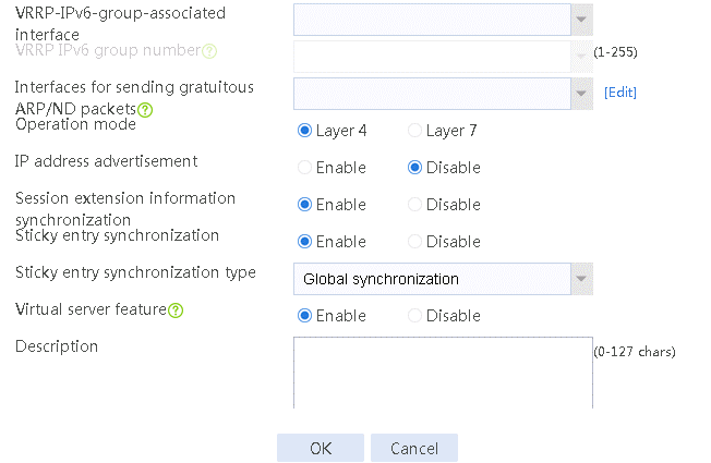
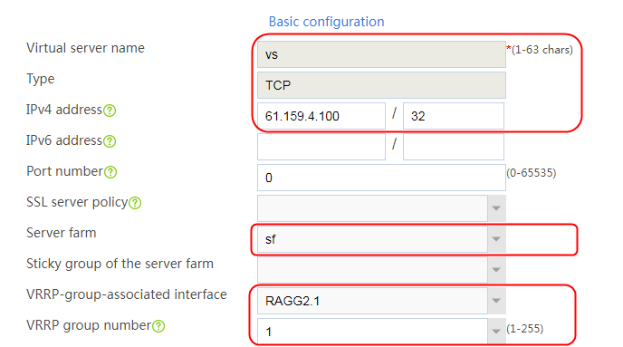
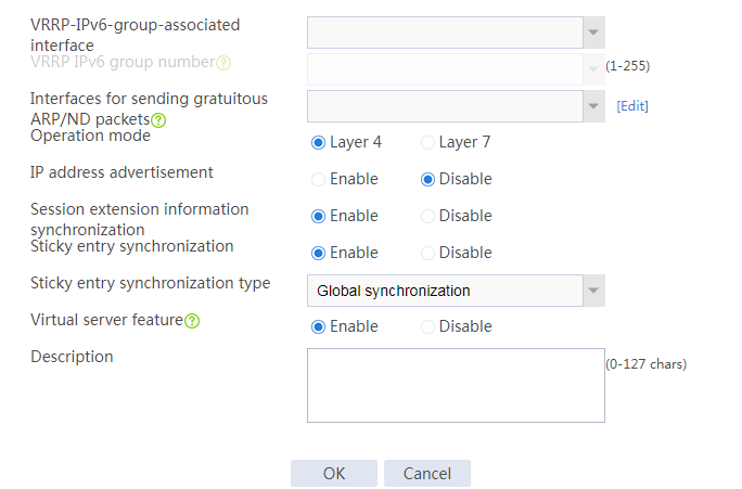
2. Click Create to add a virtual server named vs. Specify the type as TCP, VSIP as 61.159.4.100, and server farm as sf. Bind the virtual server to VRRP group 1, specify the VRRP group associated interface as Layer 3 aggregation subinterface 2.1, and enable the virtual server feature.
Figure 71 Creating a virtual server
3. Click OK.
Verifying the configuration
Viewing the HA group state
1. On the active device, navigate to the System > HA > HA page.
2. View the HA group information. After the HA group is successfully set up, on the active device, the operating mode is Active/standby, the device role is Active, and the device status is Active. The keepalive link status is normal, and the VRRP virtual IP address status is normal, which is Master.
Figure 72 HA group information on the active device

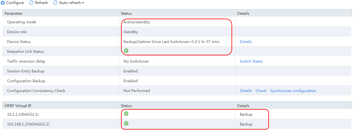
3. On the standby device, navigate to the System > HA > HA page.
4. After the HA group is successfully set up, on the standby device, the operating mode is Active/standby, the device role is Standby, and the device status is Backup. The keepalive link status is normal, and the VRRP virtual IP address status is normal, which is Backup.
Figure 73 HA group information on the standby device
Sending an FTP request
1. Send an FTP request from the host to the device with address 61.159.4.100. After the access is successful, navigate to the Monitor > Application Loading Balancing > Virtual Servers > Real-time Statistics page on the device.
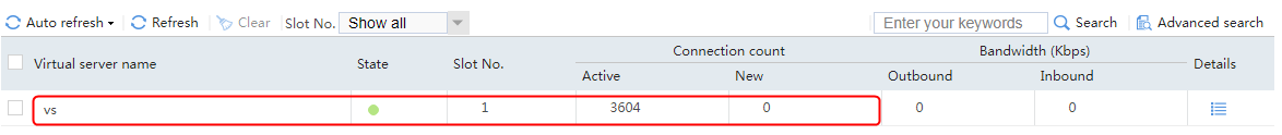
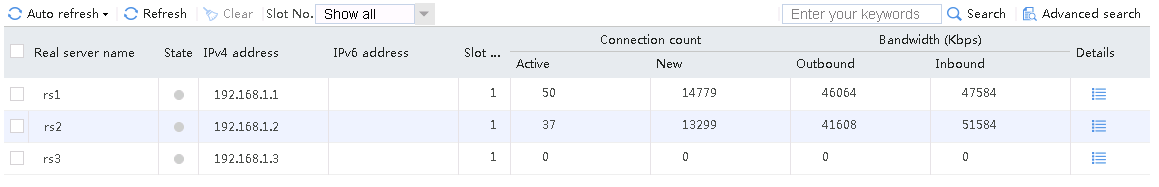
When the active device is working correctly, the virtual server statistics on the active device include new requests and concurrent requests, and the statistics on the standby device include only the concurrent requests.
Figure 74 Virtual server statistics on the active device
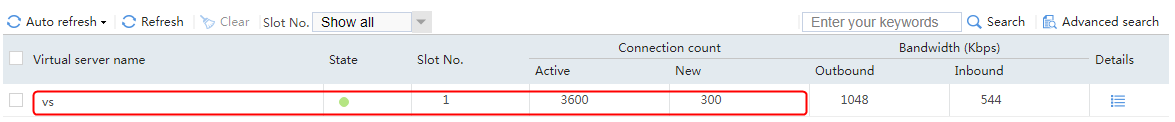
Figure 75 Virtual server statistics on the standby device
Simulating a fault on the active device
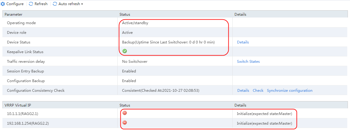
1. When the active device fails, on the active device, navigate to the System > HA > HA page.
2. After the HA group is successfully set up, on the active device, the operating mode is Active/standby, the device role is the Active, the device status is Backup. The keepalive link status is normal and the VRRP virtual IP address status is abnormal, which is Initialize.
Figure 76 HA group information on the active device
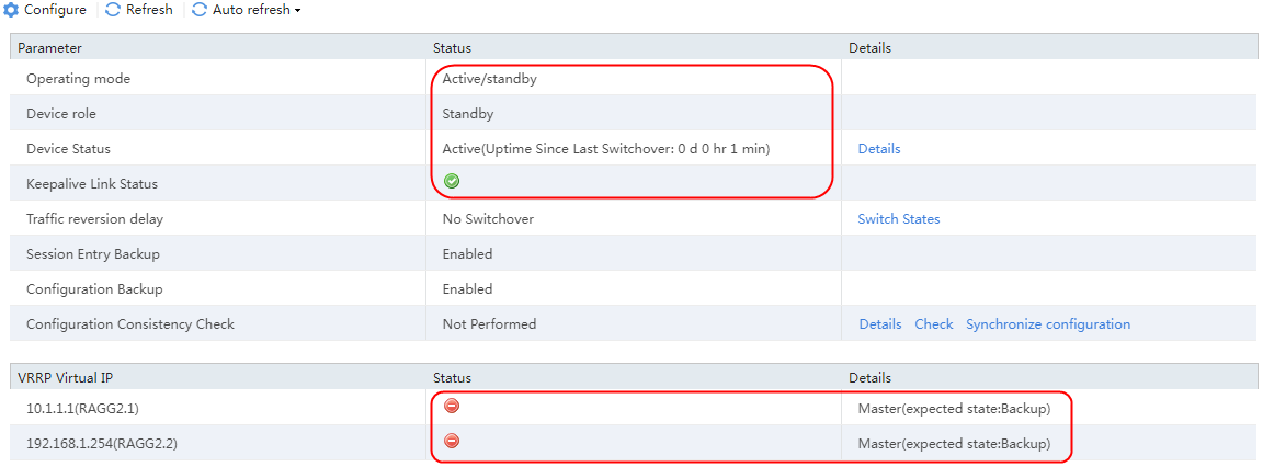
3. On the standby device, navigate to the System > HA > HA page.
4. After the HA group is successfully set up, on the standby device, the operating mode is Active/standby, the device role is Standby, and the device status is Active. The keepalive link status is normal, and the VRRP virtual IP address status is abnormal, which is Master.
Figure 77 HA on the standby device
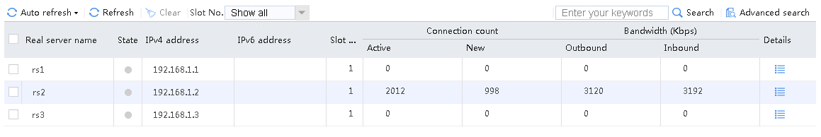
5. Send an FTP request from the host to the device with IP address 61.159.4.100. After the access is successful, navigate to the Monitor > Application Loading Balancing > Virtual Servers > Real-time Statistics page on the device.
6. When the active device fails, the virtual server statistics on the active device include the number of active connections only, and the statistics on the standby device include both the number of active connections and the number of new connections.
Figure 78 Virtual server statistics on the active device

Figure 79 Virtual server statistics on the standby device

Configuration files on the active device
#
nqa template icmp icmp
frequency 3000
reaction trigger probe-pass 1
#
interface Route-Aggregation2.1
ip address 10.1.1.253 255.255.255.0
vrrp vrid 1 virtual-ip 10.1.1.1 active
vlan-type dot1q vid 201
#
interface Route-Aggregation2.2
ip address 192.168.1.1 255.255.255.0
vrrp vrid 1 virtual-ip 192.168.1.254 active
vlan-type dot1q vid 202
#
remote-backup group
data-channel interface Route-Aggregation1
configuration sync-check interval 12
local-ip 1.1.1.1
remote-ip 1.1.1.2
device-role primary
#
loadbalance snat-pool snat
ip range start 192.168.1.101 end 192.168.1.112
arp-nd interface Route-Aggregation2.2
#
server-farm sf
predictor hash address source
probe icmp
success-criteria at-least 1
real-server rs1 port 0
success-criteria at-least 1
real-server rs2 port 0
success-criteria at-least 1
real-server rs3 port 0
success-criteria at-least 1
#
real-server rs1
ip address 192.168.1.3
#
real-server rs2
ip address 192.168.1.4
#
real-server rs3
ip address 192.168.1.5
#
virtual-server vs type tcp
virtual ip address 61.159.4.100
default server-farm sf
connection-sync enable
sticky-sync enable global
vrrp vrid 1 interface Route-Aggregation2.1
service enable
#
Configuration files on the standby device
#
nqa template icmp icmp
frequency 3000
reaction trigger probe-pass 1
#
interface Route-Aggregation2.1
ip address 10.1.1.253 255.255.255.0
vrrp vrid 1 virtual-ip 10.1.1.1 standby
vlan-type dot1q vid 201
#
interface Route-Aggregation2.2
ip address 192.168.1.1 255.255.255.0
vrrp vrid 1 virtual-ip 192.168.1.254 standby
vlan-type dot1q vid 202
#
remote-backup group
data-channel interface Route-Aggregation1
configuration sync-check interval 12
local-ip 1.1.1.2
remote-ip 1.1.1.1
device-role secondary
#
loadbalance snat-pool snat
ip range start 192.168.1.101 end 192.168.1.112
arp-nd interface Route-Aggregation2.2
#
server-farm sf
predictor hash address source
probe icmp
success-criteria at-least 1
real-server rs1 port 0
success-criteria at-least 1
real-server rs2 port 0
success-criteria at-least 1
real-server rs3 port 0
success-criteria at-least 1
#
real-server rs1
ip address 192.168.1.3
#
real-server rs2
ip address 192.168.1.4
#
real-server rs3
ip address 192.168.1.5
#
virtual-server vs type tcp
virtual ip address 61.159.4.100
default server-farm sf
connection-sync enable
sticky-sync enable global
vrrp vrid 1 interface Route-Aggregation2.1
service enable
#
Load balancing scheduling algorithm configuration examples
Example: Configuring hash algorithm and stickiness based on source address
Network configuration
As shown in the Figure 80, user requests accessing the virtual server address are forwarded through the LB device to the real servers providing HTTP services. The user requests will be load-shared among the three servers. Configure the source address hash algorithm on the LB device to distribute requests of the same user to one server. When one of the real servers fails the health check, user requests on other servers are still assigned to the same servers by source address. To ensure service continuity, use the source address-based hash algorithm together with the source address-based stickiness.

Analysis
To implement Layer 7 application load balancing based on the source address hashing and source address stickiness, complete the following configuration on the LB device:
· Configure server farm, real server, and virtual server settings on the LB device.
· Create a sticky group and set the sticky method to source address.
· Configure Layer 2 transparent transmission in the inbound direction of the switch, with the LB device as the gateway. Make sure a route is available from the host to the LB device. Configure Layer 2 transparent transmission in the outbound direction of the switch, with the LB device as the gateway. Make sure a route is available from the LB device to the server and from the server to the LB device.
Software versions used
This configuration example was created and verified on Alpha 1160P16 of L1000-AK315.
Restrictions and guidelines
When you configure hash algorithm and stickiness based on source address for load balancing, follow these restrictions and guidelines:
· Make sure the routes from the host to the LB device, from the LB device to the server, and from the server to the LB device are available, with the LB device as the gateway.
· Configure Layer 2 transparent transmission in both the inbound and outbound directions of the switch, with the LB device as the gateway.
· Configure the source address/port-based stickiness.
Procedures
Perform the following configuration on the LB device.
Assigning IP addresses to interfaces
Details not shown.
Creating a health monitoring template
1. Navigate to the LB > Global Configuration > Health Monitoring page.
2. Click Create to create an NQA template named t1. Specify the template type as TCP and destination port number as 80.
Figure 81 Creating a health monitoring template

3. Click OK.
Creating a sever farm
1. Navigate to the LB > Application Load Balancing > Server Farms page.
2. Click Create to create a server farm named sf1. Specify the scheduling algorithm as Hash source IP address and probe method as t1.
Figure 82 Creating a server farm

3. Click OK.
Configuring real servers
1. Navigate to the LB > Application Load Balancing > Server Farms page.
2. Edit the settings for server farm sf1. Create real server rs1 as the server farm member, and specify its IP address as 192.168.1.1.
Figure 83 Adding a real server
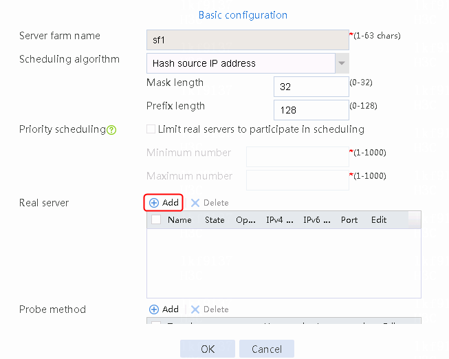
Figure 84 Creating a real server

3. Click OK.
4. Create real servers rs2 and rs3 in the same way real server rs1 is created. Specify the IP address for real servers rs2 and rs3 as 192.168.1.2 and 192.168.1.3, respectively.
Figure 85 Server farm information

Configuring a sticky group
1. Navigate to the LB > Global Configuration > Sticky Groups page.
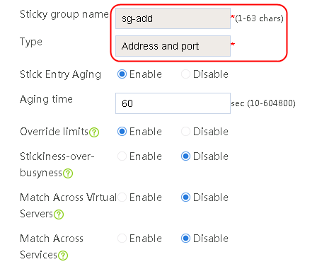
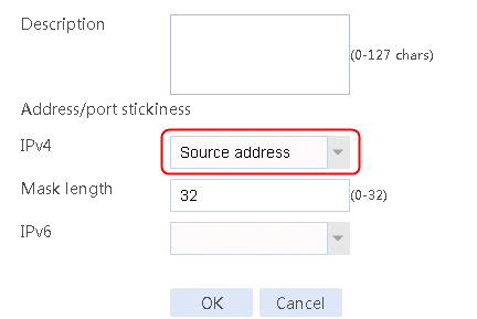
2. Click Create to create a sticky group named sg-add. Specify the type as Address and port and address/port stickiness method as Source address.
Figure 86 Creating a sticky group
3. Click OK.
Configuring a virtual server
1. Navigate to the LB > Application Load Balancing > Virtual Servers page.
2. Click Create to create a virtual server named vs. Specify the type as TCP, virtual server IP address as 61.159.4.100, and server farm as sf1. Specify sticky group sg-add with the source address/port sticky method, and enable the virtual server feature.
Figure 87 Creating a virtual server


3. Click OK.
Verifying the configuration
Disabling real servers rs2 and rs3 and view statistics
For the virtual server, specify the source address–based sticky group of the server farm as sg-add. First, disable real servers rs2 and rs3.
Figure 88 Viewing the status of server farm sf1
![]()
Send an HTTP request from the client with a source address and multiple ports to the server, and view the real server statistics. Only rs1 has traffic.
Figure 89 Viewing real server statistics
Enabling real servers rs2 and rs3 and view statistics
Enable real servers rs2 and rs3, and view load balancing information of the real servers.
Figure 90 Viewing the status of server farm sf1

Because the virtual server is configured with the source address stickiness, when the real server fails and then succeeds in the probe check, the requests with the same source address and different ports are still distributed to the same real server. In the real server statistics, only rs1 has traffic.
Figure 91 Viewing real server statistics
Configuration files
#
nqa template tcp t1
destination port 80
#
sticky-group sg-add type address-port
ip source
#
server-farm sf1
predictor hash address source
probe t1
success-criteria at-least 1
real-server rs1 port 0
success-criteria at-least 1
real-server rs2 port 0
success-criteria at-least 1
real-server rs3 port 0
success-criteria at-least 1
#
real-server rs1
ip address 192.168.1.1
#
real-server rs2
ip address 192.168.1.2
#
real-server rs3
ip address 192.168.1.3
#
virtual-server vs type tcp
virtual ip address 61.159.4.100
default server-farm sf1 sticky sg-add
connection-sync enable
sticky-sync enable global
service enable
#
Example: Configuring least connection scheduling algorithm and source address-based stickiness
Network configuration
As shown in the Figure 92, user requests accessing the virtual server address are forwarded through the LB device to the real servers providing HTTP services. The user requests will be load-shared among the three servers. Configure the least connection algorithm and source address stickiness on the LB device to distribute requests of the same user to one server even when traffic is not evenly distributed. Configure the slow online feature to avoid distributing all new traffic to a server that fails and then succeeds in the health check, preventing repeated up and down issues of the server.

Analysis
To implement Layer 7 application load balancing based on the least connection algorithm, source address stickiness, and slow online, complete the following configuration on the LB device:
· Configure the slow online feature on the server farm. You must use the least connection algorithm together with the slow online feature. If not, when the server fails and then succeeds in the health check, all new requests will be distributed to the server. The server might go down again.
· Create a sticky group with the source address/port sticky method.
· Configure Layer 2 transparent transmission in the inbound direction of the switch, with the LB device as the gateway. Make sure a route is available from the host to the LB device. Configure Layer 2 transparent transmission in the outbound direction of the switch, with the LB device as the gateway. Make sure a route is available from the LB device to the server and from the server to the LB device.
Software versions used
This configuration example was created and verified on Alpha 1160P16 of L1000-AK315.
Restrictions and guidelines
When you configure load balancing based on the least connection algorithm, source address stickiness, and slow online, follow these restrictions and guidelines:
· Make sure the routes from the host to the LB device, from the LB device to the server, and from the server to the LB device are available, with the LB device as the gateway.
· Configure Layer 2 transparent transmission in both the inbound and outbound directions of the switch, with the LB device as the gateway.
· Enable the slow online feature for the server farm.
· Configure the source address/port-based stickiness.
Procedures
Perform the following configuration on the LB device.
Assigning IP addresses to interfaces
Details not shown.
Creating a health monitoring template
1. Navigate to the LB > Global Configuration > Health Monitoring page.
2. Click Create to create an NQA template named t1. Specify the template type as TCP and destination port number as 80.
Figure 93 Creating a health monitoring template

3. Click OK.
Creating a server farm
1. Navigate to the LB > Application Load Balancing > Server Farms page.
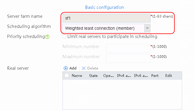
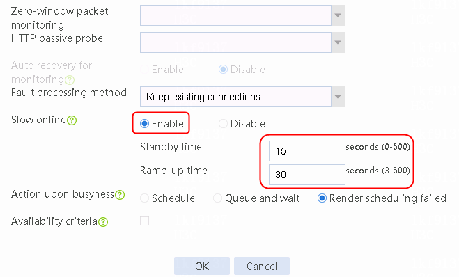
2. Click Create to create a server farm named sf1, specify the scheduling algorithm as Weighted least connection (member) and probe method as t1, and enable the slow online feature.
Figure 94 Creating a server farm

3. Click OK.
Configuring real servers
1. Navigate to the LB > Application Load Balancing > Server Farms page.
2. Edit the settings for server farm sf1. Create real server rs1 as the server farm member, and specify its IP address as 192.168.1.1.
Figure 95 Adding a real server
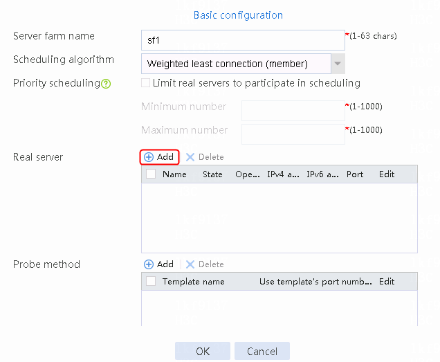
Figure 96 Creating a real server

3. Click OK.
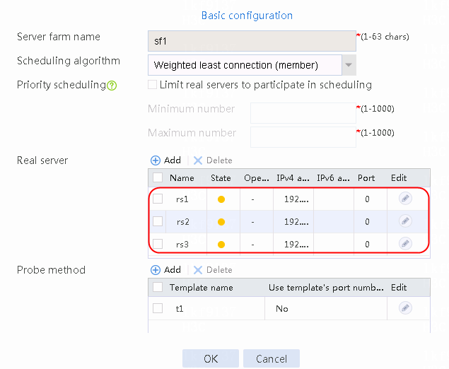
4. Create real servers rs2 and rs3 in the same way real server rs1 is created. Specify the IP address for real servers rs2 and rs3 as 192.168.1.2 and 192.168.1.3, respectively.
Figure 97 Server farm information
Configuring a sticky group
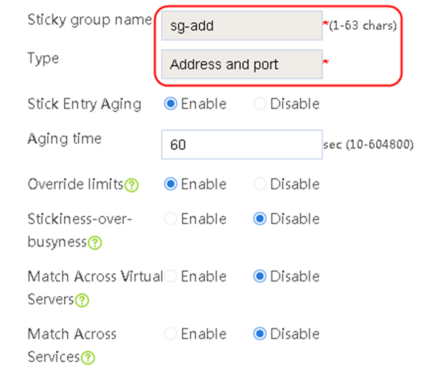
1. Navigate to the LB > Global Configuration > Sticky Groups page.
2. Click Create to create a sticky group named sg-add. Specify the type as Address and port and sticky method as Source address.
Figure 98 Creating a sticky group

3. Click OK.
Configuring a virtual server
1. Navigate to the LB > Application Load Balancing > Virtual Servers page.
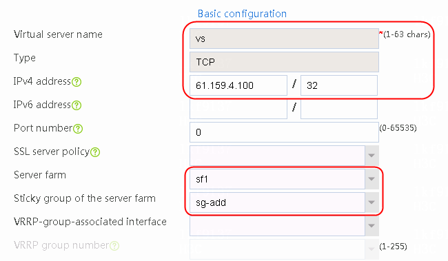
2. Click Create to create a virtual server named vs. Specify the type as TCP, virtual server IP address as 61.159.4.100, and server farm as sf1. Specify sticky group sg-add of the address/port type, and enable the virtual server feature.
Figure 99 Creating a virtual server

3. Click OK.
Verifying the configuration
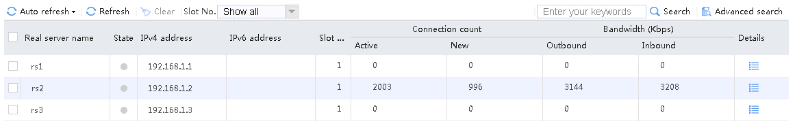
1. Verify and view the server farm information. Configure the delay timer of the three real servers rs1, rs2 and rs3 on the server side as 100 ms, 200 ms, and 300 ms, respectively. Because the server farm is configured with a weighted least connection algorithm, the traffic volumes on the real servers are in the sequence of rs1 > rs2 > rs3.
Figure 100 Real server statistics
2. Send an access request from the client. According to the real server traffic statistics, the traffic is distributed to rs3.
Figure 101 Real server statistics
Send an access request from the client again. According to the real server traffic statistics, the traffic is still distributed to rs3.
Figure 102 Real server statistics
3. Configure the slow online feature for the server farm. The health monitoring of real servers rs1 and rs2 is successful. Disable real server rs3. The traffic is evenly distributed to real servers rs1 and rs2.
Figure 103 Status of server farm sf1
![]()
Send an HTTP request from the client to the server. According to the statistics of the real servers, servers rs1 and rs2 share the traffic evenly.
Figure 104 Real server statistics
4. Enable real server rs3, and view the load balancing information of the real servers.
Figure 105 Status of server farm sf1

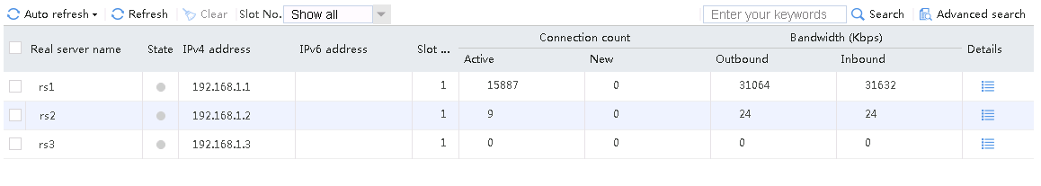
Because the server farm is configured with the slow online feature, when the probe method on server rs3 is successful, all new traffic will not be allocated to rs3. The three real servers will share new traffic. View traffic statistics on rs3. After the probe method on the server rs3 is successful, the traffic volume slowly increases.
Figure 106 Real server statistics
Click Refresh.
Figure 107 Real server statistics
5. Disable the slow online feature of the server farm. Health monitoring of real servers rs1 and rs2 is successful. Disable real server rs3. The traffic is evenly distributed to real servers rs1 and rs2.
Figure 108 Status of server farm sf1
![]()
Send an HTTP request from the client to the server to view the statistics of the real servers. Servers rs1 and rs2 share the traffic evenly.
Figure 109 Real server statistics

6. Enable real server rs3, and view load balancing information of the real servers.
Figure 110 Status of server farm sf1

The server farm is configured with the least connection algorithm and the slow online feature. When health monitoring on server rs3 is successful, all new traffic will be allocated to rs3. View the traffic statistics on rs3. After health monitoring on server rs3 is successful, the traffic volume quickly increases.
Figure 111 Viewing real server statistics

Click Refresh.
Figure 112 Real server statistics
Configuration files
#
nqa template tcp t1
destination port 80
#
server-farm sf1
predictor least-connection member
probe t1
success-criteria at-least 1
slow-online standby-time 15 ramp-up-time 30
real-server rs1 port 0
success-criteria at-least 1
real-server rs2 port 0
success-criteria at-least 1
real-server rs3 port 0
success-criteria at-least 1
#
real-server rs1
ip address 192.168.1.1
#
real-server rs2
ip address 192.168.1.2
#
real-server rs3
ip address 192.168.1.3
#
sticky-group sg-add type address-port
ip source
#
virtual-server vs type tcp
virtual ip address 61.159.4.100
default server-farm sf1 sticky sg-add
connection-sync enable
sticky-sync enable global
service enable
#
Layer 7 application load balancing configuration examples
Example: Configuring URL-based Layer 7 load balancing
Network configuration
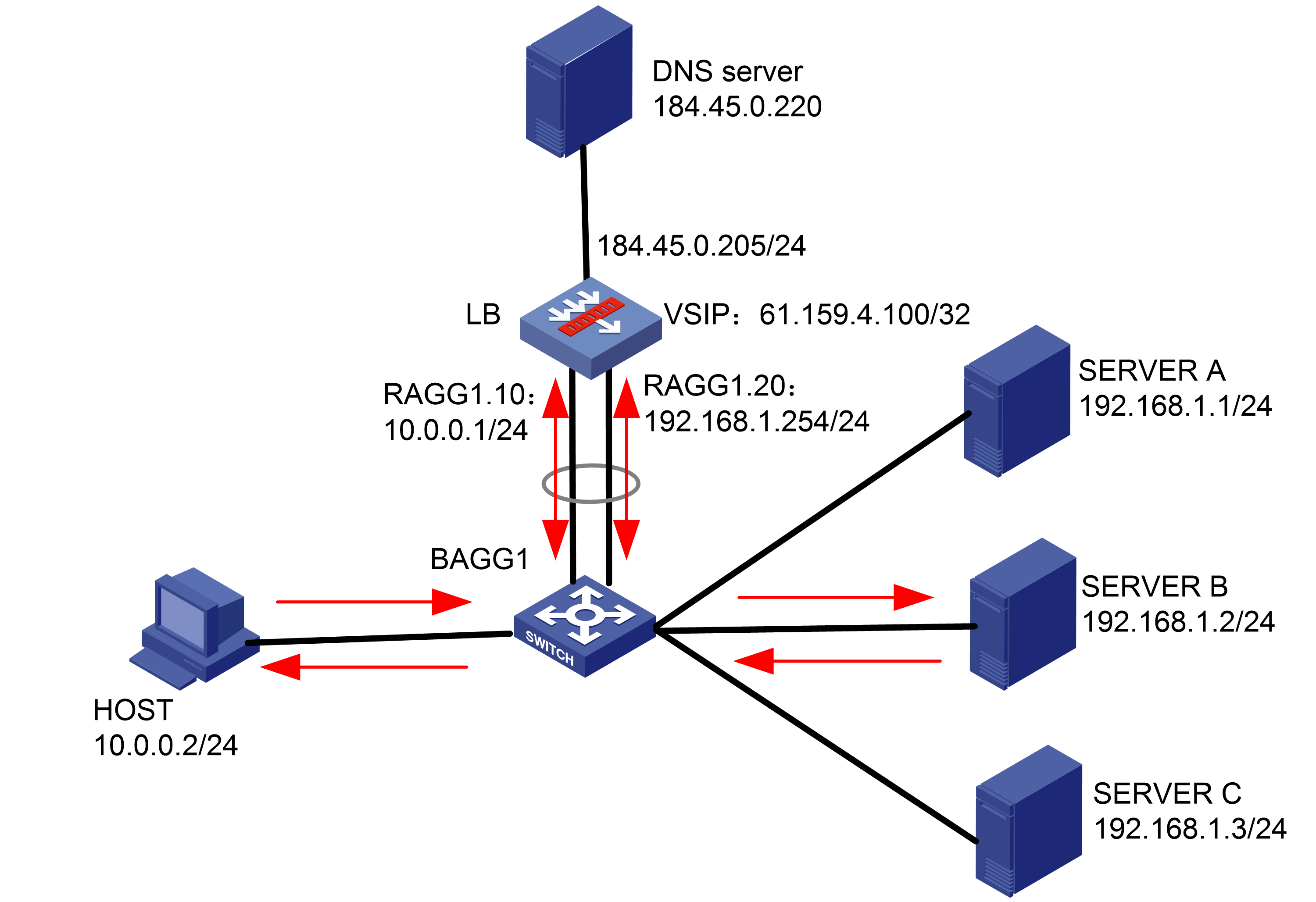
As shown in the Figure 113, the host accesses six servers through the LB device, and all the six servers Server A, Server B, Server C, Server D, Server E, and Server F can provide HTTP services. The traffic from the host will be load-shared among the six servers according to the URLs accessed by the host. The requests containing sports, government, and news in the URLs are distributed to Server A and Server D, the requests containing finance, technology, and shopping in the URLs are distributed to Server B and Server E, and requests containing other URLs are distributed to Server C and Server F.
Analysis
To implement URL-based Layer 7 application load balancing, complete the following configuration on the LB device:
· Configure server farm, real server, and virtual server settings on the LB device.
· Configure LB policy, class, and action settings. Configure rules for matching URLs in the class, so that the LB device can distribute requests containing sports, government, and news in the URLs to Server A and Server D, requests containing finance, technology, and shopping in the URLs to Server B and Server E, and requests containing other URLs to Server C and Server F.
Software versions used
This configuration example was created and verified on Alpha 1160P16 of L1000-AK315.
Restrictions and guidelines
When you configure URL-based Layer 7 application load balancing, follow these restrictions and guidelines:
· Make sure the routes from the host to the LB device, from the LB device to the server, and from the server to the LB device are available, with the LB device as the gateway.
· Configure Layer 2 transparent transmission in both the inbound and outbound directions of the switch, with the LB device as the gateway.
· Configure the source address/port-based stickiness.
· If an HTTP packet has multiple requests, configure load balancing on a per request basis.
Procedures
Perform the following configuration on the LB device.
Assigning IP addresses to interfaces
Details not shown.
Creating a health monitoring template
1. Navigate to the LB > Global Configuration > Health Monitoring page.
2. Click Create to create a template named t1, specify the type as HTTP, and set the expected status code to 200.
Figure 114 Creating a health monitoring template

3. Click OK.
Creating server farms
1. Navigate to the LB > Application Load Balancing > Server Farms page.
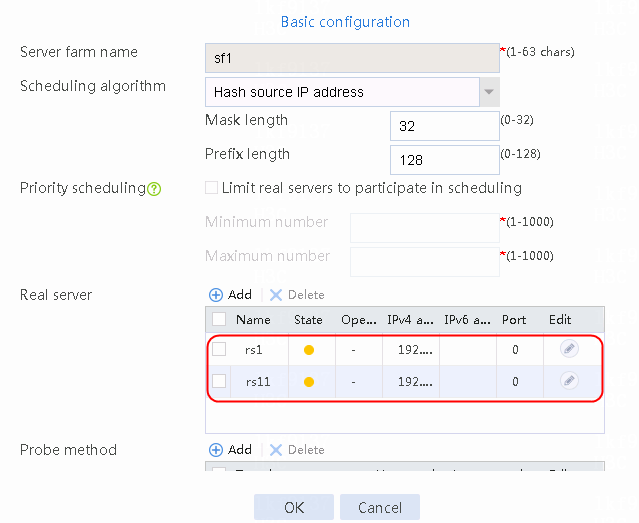
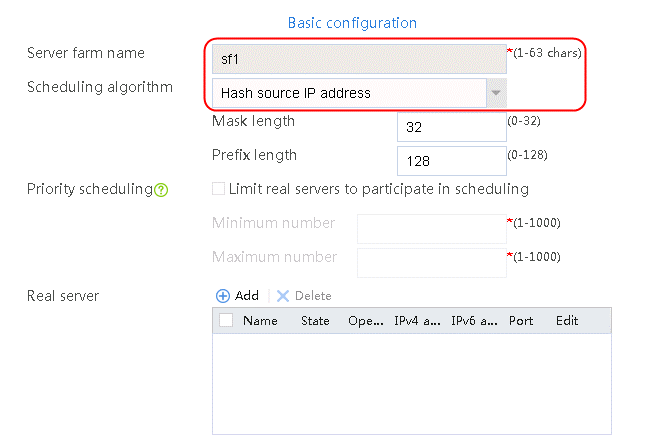
2. Click Create to create a server farm named sf1. Specify the scheduling algorithm as Hash source IP address and probe method as t1.
Figure 115 Creating a server farm


3. Click OK.
4. Create server farms sf2 and sf3 in the same way sf1 is created.
Figure 116 Server farm information

Configuring real servers
1. Navigate to the LB > Application Load Balancing > Server Farms page.
2. Edit the settings for server farm sf1. Create real server rs1 as the server farm member, and specify its IP address as 192.168.1.1.
Figure 117 Adding a real server

Figure 118 Creating a real server

3. Click OK.
Figure 119 Real server information
4. Click OK.
5. Create the other five real servers in the same way rs1 is created:
a. Navigate to the LB > Application Load Balancing > Server Farms page. Edit server farm sf1, and add a real server. Create real server rs11 as shown in the figure above, and configure its IPv4 address as 192.168.1.11.
b. Navigate to the LB > Application Load Balancing > Server Farms page. Edit server farm sf2, and add real servers. Create real servers rs2 and rs12 as shown in the figure above, and configure their IPv4 addresses as 192.168.1.2 and 192.168.1.12, respectively.
c. Navigate to the LB > Application Load Balancing > Server Farms page. Edit server farm sf3, and add real servers. Create real servers rs3 and rs13 as shown in the figure above, and respectively configure their IPv4 addresses as 192.168.1.3 and 192.168.1.13, respectively..
Configuring a sticky group
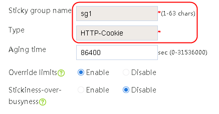
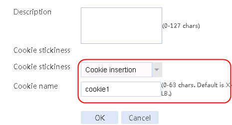
1. Create a sticky group of HTTP-Cookie type. Configure the sticky method as Cookie insertion, and configure the cookie name as cookie1. (Cookie insertion inserts the Set-cookie field in HTTP response packets sent by the server for stickiness processing).
2. Navigate to the LB > Global Configuration > Sticky Groups page.
3. Click Create to create a sticky group named sg1, set the type to http-cookie, the sticky method to Cookie insertion, and the cookie name to cookie1.
Figure 120 Creating a sticky group
4. Click OK.
Configuring LB classes
1. Navigate to the LB > Application Load Balancing > Advanced Policies > Class page.
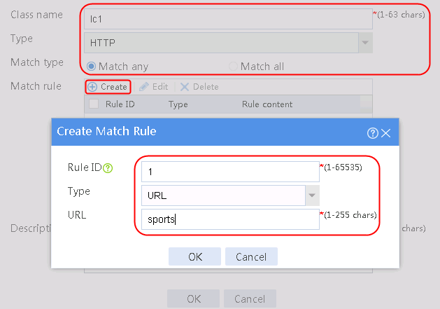
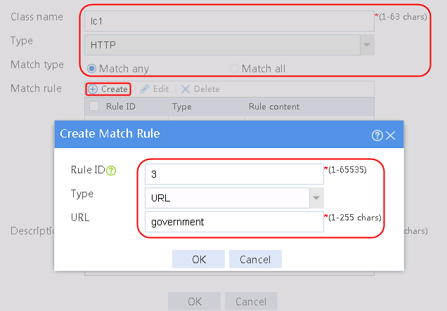
2. Click Create to create a class named lc1. Set the type to HTTP and the match type to Match any:
¡ Add a rule with ID 1, specify the type as URL, and the URL content as sports, and then click OK.
¡ Add a rule with ID 2, specify the type as URL, and the URL content as news, and then click OK.
¡ Add a rule with ID 3, specify the type as URL, and the URL content as government, and then click OK.
Figure 121 Creating class lc1
3. Click OK.

4. Click OK.
5. Click OK.
Figure 122 Class information

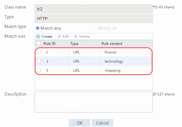
6. Create lc2 in the same way lc1 is created, and configure the parameters.
Figure 123 Class lc2 information
Configuring LB actions
1. Navigate to the LB > Application Load Balancing > Advanced Policies > Action page.
2. Click Create to create an action named la1, specify the type as HTTP, the primary server farm as sf1, and the sticky group as sg1.
Figure 124 Creating an action

3. Click OK.
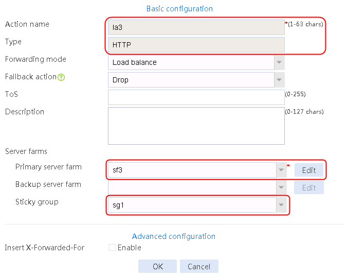
4. Create LB actions la2 and la3 in the same way la1 is created. Specify the primary server farm for la2 as sf2, and primary server farm for la3 as sf3, as shown in Figure 125 and Figure 126.
Figure 125 Configuring LB action la2
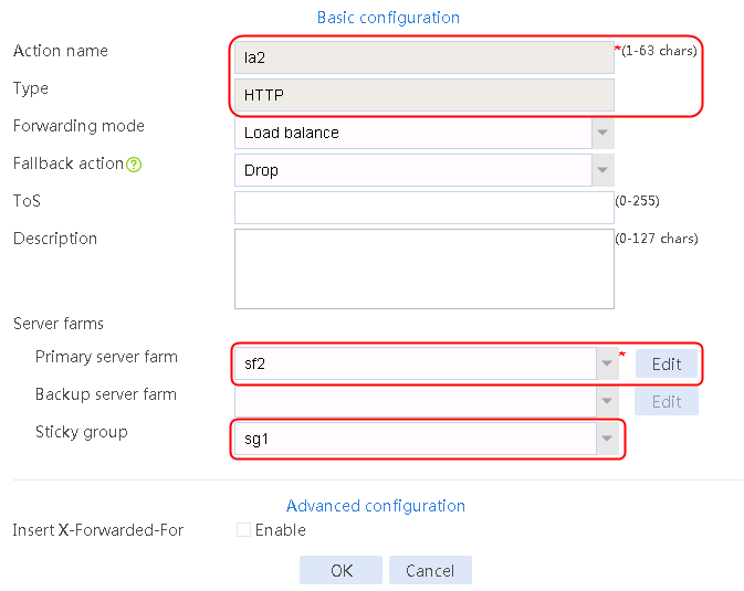
Figure 126 Configuring LB action la3
Configuring an LB policy
1. Navigate to the LB > Application Load Balancing > Advanced Policies > Load Balancing Policy page.
2. Click Create to create a policy named lp1, specify the type as HTTP, specify the default action as la3, and click Create in the rule. In the Create Rule dialog box, specify class lc1 and action la1, and click OK. Then, click Create again, specify class lc2 and action la2, and click OK.
Figure 127 Creating an LB policy
3. Click OK.
Figure 128 Policy lp1 configuration information
4. Click OK.
Configuring a parameter profile
1. Navigate to the LB > Application Load Balancing > Parameter Profiles page.
2. Click Create to create a parameter profile named pp1, specify the type as HTTP, and enable the per-packet load balancing.
Figure 129 Creating a parameter profile

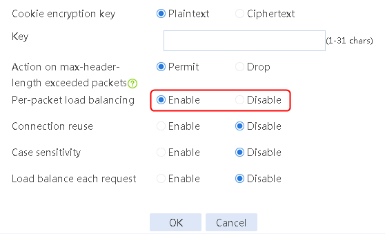
3. Click OK.
Configuring a virtual server
1. Navigate to the LB > Application Load Balancing > Virtual Servers page.
2. Click Create to create a virtual server named vs. Specify the type as HTTP and the virtual IP address as 61.159.4.100. Specify LB policy lp1 and parameter profile pp1, and enable the virtual server feature.
Figure 130 Creating a virtual server


3. Click OK.
Verifying the configuration
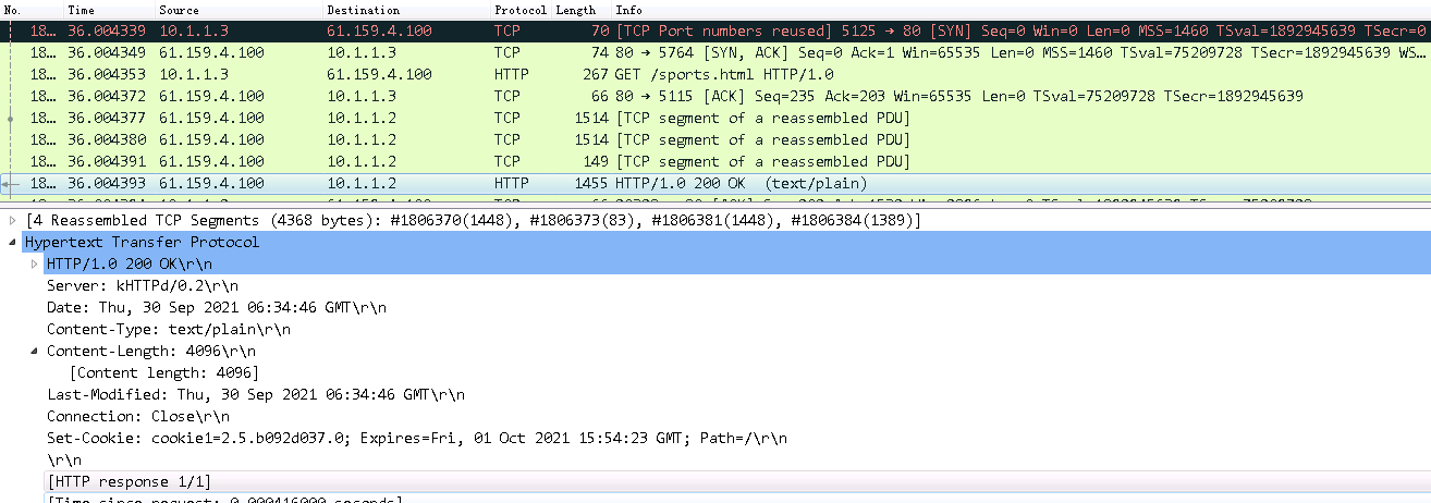
Initiate seven request packets containing aaa, sports, news, government, finance, technology, and shopping in the URLs from the host to the HTTP server. The access is successful, and you can view the virtual server and real server statistics on the LB device, and from the captured packets on the host. The response packets sent back by the server have a set-cookie field in the header.
The virtual server has statistics.
Figure 131 Virtual server statistics
Host requests containing sports, news, and government in the URLs match LB class lc1. Real server rs1 has traffic statistics.
Figure 132 Real server statistics
Hosts requests containing finance, technology, and shopping in the URLs match LB class lc2. Real server rs12 has traffic statistics at this time.
Figure 133 Real server statistics
Host requests containing aaa in the URLs fail to match LB classes lc1 and lc2, and are forwarded through lc3 (default setting). Real server rs13 has traffic statistics at this time.
Figure 134 Real server statistics
Initiate host requests containing aaa, sports, news, government, finance, technology, and shopping in the URLs. The statistics are as follows:
Figure 135 Virtual server statistics
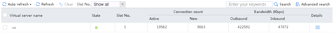
Figure 136 Server farm statistics
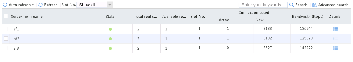
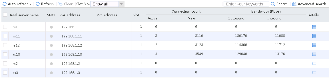
Figure 137 Real server statistics
Initiates host requests containing sports, news, and government in the URLs to verify that cookie insertion stickiness is effective. Captures packets to verify that the set-cookie field in the header of the response packets returned by the server is cookie1=2.5.b092d037.0.
Figure 138 Captured packet information
According to the real server statistics, only rs1 is matched.
Figure 139 Real server statistics
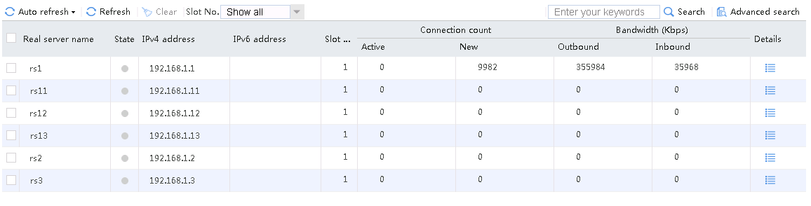
Initiate a host request with the cookie value Cookie1=2.5.b092d037.0 again. Verify that the stickiness has taken effect. Only rs1 has statistics.
Figure 140 Real server statistics

Configuration files
#
nqa template http t1
expect status 200
#
server-farm sf1
predictor hash address source
probe t1
success-criteria at-least 1
real-server rs1 port 0
success-criteria at-least 1
real-server rs11 port 0
success-criteria at-least 1
#
server-farm sf2
predictor hash address source
probe t1
success-criteria at-least 1
real-server rs2 port 0
success-criteria at-least 1
real-server rs12 port 0
success-criteria at-least 1
#
server-farm sf3
predictor hash address source
probe t1
success-criteria at-least 1
real-server rs3 port 0
success-criteria at-least 1
real-server rs13 port 0
success-criteria at-least 1
#
real-server rs1
ip address 192.168.1.1
#
real-server rs11
ip address 192.168.1.11
#
real-server rs2
ip address 192.168.1.2
#
real-server rs12
ip address 192.168.1.12
#
real-server rs3
ip address 192.168.1.3
#
real-server rs13
ip address 192.168.1.13
#
loadbalance class lc1 type http match-any
match 1 url sports
match 2 url news
match 3 url government
#
loadbalance class lc2 type http match-any
match 1 url finance
match 2 url technology
match 3 url shopping
#
loadbalance action la1 type http
server-farm sf1 sticky sg1
#
loadbalance action la2 type http
server-farm sf2 sticky sg1
#
loadbalance action la3 type http
server-farm sf3 sticky sg1
#
loadbalance policy lp1 type http
class lc1 action la1
class lc2 action la2
default-class action la3
#
sticky-group sg1 type http-cookie
cookie insert name cookie1
#
parameter-profile pp1 type http
rebalance per-request
#
virtual-server vs type http
virtual ip address 61.159.4.100
parameter http pp1
lb-policy lp1
sticky-sync enable global
service enable
#
Example: Configuring host-based Layer 7 load balancing
Network configuration
As shown in the Figure 141, the DNS server resolves the virtual server address for the domain name in the DNS request sent from the host. The host then initiates access requests to the virtual server address to accesses three servers through the LB device. All three servers can provide HTTP services. The access requests will be load-shared among the three servers according to the LB policy.
Analysis
To implement host-based Layer 7 application load balancing, complete the following configuration on the LB device:
· Configure server farm, real server, and virtual server settings on the LB device.
· Configure LB policy, class and action settings. Configure rules to match the host in the class, so that the LB device can distribute requests with domain name www.aaa.com to Server A, requests with domain name www.bbb.com to Server B, and requests with domain name www.ccc.com to Server C.
· The DNS server resolves domain names, and return the resolved IP addresses to the host.
· The virtual server address is the IP address resolved by the DNS server, so that the host can initiate a request to the virtual server.
Software versions used
This configuration example was created and verified on Alpha 1160P16 of L1000-AK315.
Restrictions and guidelines
When you configure host-based Layer 7 application load balancing, follow these restrictions and guidelines:
· A route is available between the host and DNS server.
· Configure Layer 2 transparent transmission in the inbound direction of the switch, with the LB device as the gateway. Make sure a route is available from the host to the LB device. Configure Layer 2 transparent transmission in the outbound direction of the switch, with the LB device as the gateway. Make sure a route is available from the LB device to the server and from the server to the LB device.
· Make sure the IP address resolved by the DNS server from the DNS request is the same as the virtual server IP address on the LB device.
Procedures
Perform the following configuration on the LB device.
Assigning IP addresses to interfaces
Details not shown.
Creating a health monitoring template
1. Navigate to the LB > Global Configuration > Health Monitoring page.
2. Click Create to create a template named t1, specify the type as HTTP, and set the expected status code to 200.
Figure 142 Creating a health monitoring template

3. Click OK.
Creating server farms
1. Navigate to the LB > Application Load Balancing > Server Farms page.
2. Click Create to create a server farm named sf1. Specify the scheduling algorithm as Hash source IP address and probe method as t1.
Figure 143 Creating a server farm

3. Click OK.
4. Create server farms sf2 and sf3 in the same way sf1 is created.
Figure 144 Server farm information
Configuring real servers
1. Navigate to the LB > Application Load Balancing > Server Farms page.
2. Edit the settings for server farm sf1. Create real server rs1 as the server farm member, and specify its IP address as 192.168.1.1.
Figure 145 Adding a real server

Figure 146 Creating a real server

3. Click OK.
Figure 147 Real server information

4. Click OK.
5. Create real server rs2 in the same way rs1 is created:
a. Navigate to the LB > Application Load Balancing > Server Farms page.
b. Edit server farm sf2 to add a real server.
c. Create real server rs2 as shown in the figure above, and configure its IPv4 address as 192.168.1.2.
6. Create real server rs3 in the same way rs1 is created:
a. Navigate to the LB > Application Load Balancing > Server Farms page.
b. Edit server farm sf3 to add a real server.
c. Create real server rs3 as shown in the figure above, and configure its IPv4 address as 192.168.1.3.
Configuring LB classes
1. Navigate to the LB > Application Load Balancing > Advanced Policies > Classes page.
2. Click Create to create a class named lc1, and set the type to HTTP and the match type to Match all.
3. In the Create Match Rule dialog box, specify the rule ID as 1, the type as HTTP Header, the header name as host, and the header value as www.aaa.com.
Figure 148 Creating a class
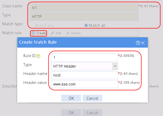
4. Click OK.
Figure 149 Class information
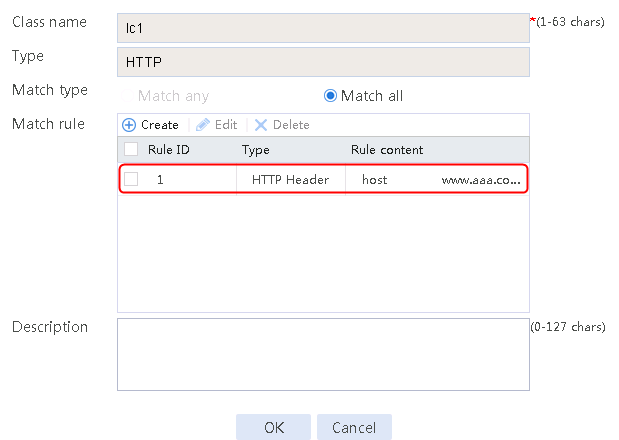
5. Create lc2 and lc3 respectively in the same way lc1 is created. Specify the header value as www.bbb.com for lc2 and www.ccc.com for lc3.
Configuring LB actions
1. Navigate to the LB > Application Load Balancing > Advanced Policies > Action page.
2. Click Create to create an LB action named la1, specify the type as HTTP, and set the primary server farm to sf1.
Figure 150 Creating an action
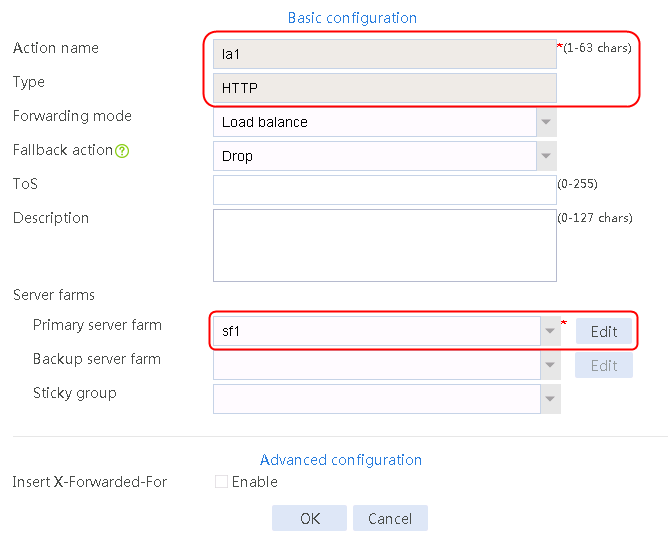
3. Click OK.
4. Create la2 and la3 in the same way la1 is created. The primary server farm of la2 is sf2, and the primary server farm of la3 is sf3.
Configuring an LB policy
1. Navigate to the LB > Application Load Balancing > Advanced Policies > Load Balancing Policy page.
2. Click Create to create a policy named lp1, specify the type as HTTP, and click Create to create a rule.
3. In the Create Rule dialog box, set the class to lc1 and the action to la1, and click OK.
4. Click Create again. Specify the class as lc2 and the action as la2, and click OK.
5. Click Create again. Specify the class as lc3 and the action as la2, and click OK.
Figure 151 Creating a policy
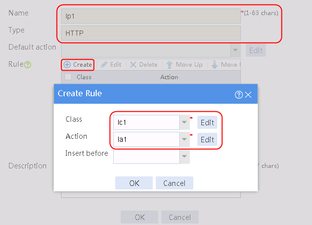
Figure 152 Policy information
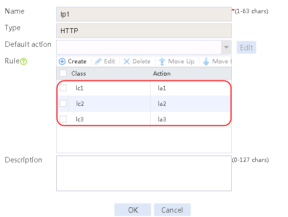
6. Click OK.
Configuring a virtual server
1. Navigate to the LB > Application Load Balancing > Virtual Servers page.
2. Click Create to create a virtual server named vs. Specify the type as HTTP and virtual IP address as 61.159.4.100, specify LB policy lp1, and enable the virtual server feature.
Figure 153 Creating a virtual server


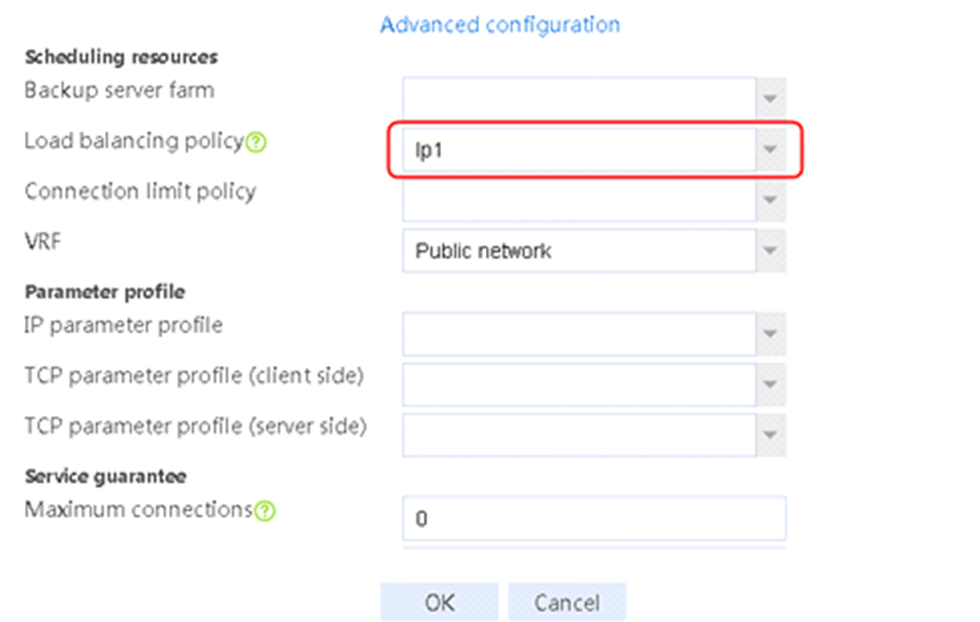
3. Click OK.
Verifying the configuration
When the host initiates a request to visit www.aaa.com, rs1 has statistics. When the host initiates a request to visit www.bbb.com, rs2 has statistics. When the host initiates a request to visit www.ccc.com, rs3 has statistics. View the virtual server and real server statistics:
Figure 154 Virtual server statistics
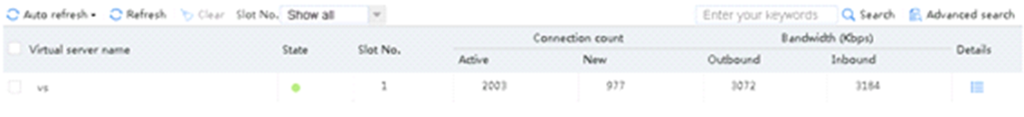
The host request to visit www.aaa.com matches LB class lc1, and rs1 has traffic statistics.
Figure 155 Real server statistics

The host request to visit www.bbb.com matches LB class lc2, and rs2 has traffic statistics.
Figure 156 Viewing real server statistics
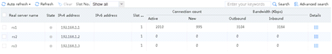
The host request to visit www.ccc.com matches LB class lc3, and rs3 has traffic statistics.
Figure 157 Viewing real server statistics
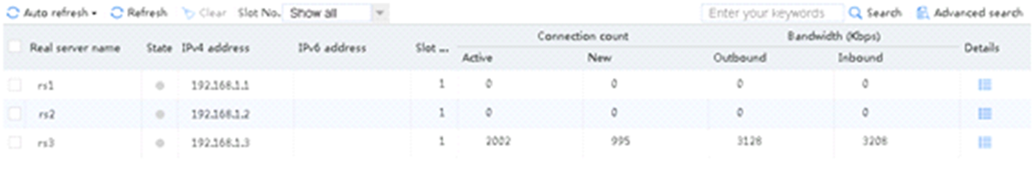
Configuration files
#
nqa template http t1
expect status 200
#
server-farm sf1
predictor hash address source
probe t1
success-criteria at-least 1
real-server rs1 port 0
success-criteria at-least 1
#
server-farm sf2
predictor hash address source
probe t1
success-criteria at-least 1
real-server rs2 port 0
success-criteria at-least 1
#
server-farm sf3
predictor hash address source
probe t1
success-criteria at-least 1
real-server rs3 port 0
success-criteria at-least 1
#
loadbalance class lc1 type http
match 1 header host value www.aaa.com
#
loadbalance class lc2 type http
match 1 header host value www.bbb.com
#
loadbalance class lc3 type http
match 1 header host value www.ccc.com
#
loadbalance action la1 type http
server-farm sf1
#
loadbalance action la2 type http
server-farm sf2
#
loadbalance action la3 type http
server-farm sf3
#
loadbalance policy lp1 type http
class lc1 action la1
class lc2 action la2
class lc3 action la3
#
real-server rs1
ip address 192.168.1.1
#
real-server rs2
ip address 192.168.1.2
#
real-server rs3
ip address 192.168.1.3
#
virtual-server vs type http
virtual ip address 61.159.4.100
lb-policy lp1
sticky-sync enable global
service enable
#
Example: Configuring priority scheduling-based application load balancing
Network configuration
As shown in the Figure 158, the host accesses three servers through the LB device. Three servers Server A, Server B and Server C can provide HTTP services. The LB device distributes user requests based on the server priorities and the number of real servers allowed to be scheduled in the server farm to achieve load balancing.
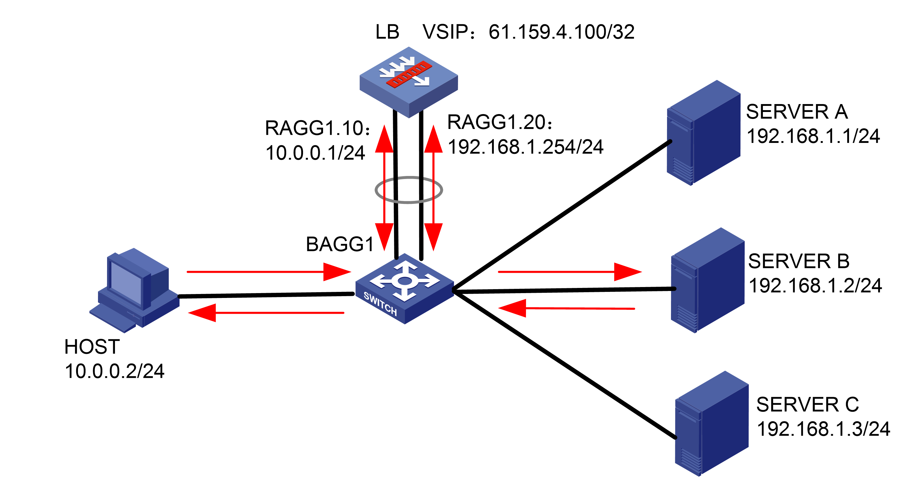
Analysis
To implement priority scheduling-based Layer 7 application load balancing, complete the following configuration on the LB device:
· Configure server farm, real server, and virtual server settings on the LB device.
· To distribute traffic to only the server with the highest priority, set the number of real servers available for scheduling in the server farm to 1, and set the priorities for the real servers to 4, 8, and 1, respectively.
· To distribute traffic to two servers, set the number of real servers available for scheduling in the server farm to 2, and set the priorities for the real servers to 4, 8, and 1, respectively.
· Configure Layer 2 transparent transmission in the inbound direction of the switch, with the LB device as the gateway. Make sure a route is available from the host to the LB device. Configure Layer 2 transparent transmission in the outbound direction of the switch, with the LB device as the gateway. Make sure a route is available from the LB device to the server and from the server to the LB device.
Software versions used
This configuration example was created and verified on Alpha 1160P16 of L1000-AK315.
Restrictions and guidelines
When you configure priority scheduling-based Layer 7 application load balancing, follow these restrictions and guidelines:
· Makes sure the routes from the host to the LB device, from the LB device to the server, and from the server to the LB device are available, with the LB device as the gateway.
· Configure Layer 2 transparent transmission in both the inbound and outbound directions of the switch, with the LB device as the gateway.
· Configure the number of real servers available for scheduling in the server farm, and set different priorities for the real servers.
Procedures
Perform the following configuration on the LB device.
Assigning IP addresses to interfaces
Details not shown.
Creating a health monitoring template
1. Navigate to the LB > Global Configuration > Health Monitoring page.
2. Click Create to create a template named t1, specify the type as HTTP, and set the expected status code to 200.
Figure 159 Creating a health monitoring template

3. Click OK.
Creating a server farm
1. Navigate to the LB > Application Load Balancing > Server Farms page.
2. Click Create to create a server farm named sf1. Specify the scheduling algorithm as Hash source IP address and probe method as t1. Select the Limit real servers to participate in scheduling option, and set both minimum number and maximum number to 1.
Figure 160 Creating a server farm
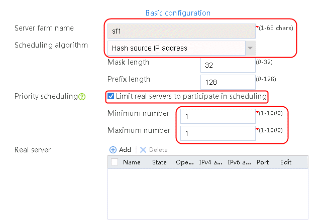

3. Click OK.
Configuring real servers
1. Navigate to the LB > Application Load Balancing > Server Farms page.
2. Edit server farm sf1, and add a real server with name rs1 and IP address 192.168.1.1. Specify the priority as 4 and the server farm as sf1.
Figure 161 Adding a real server
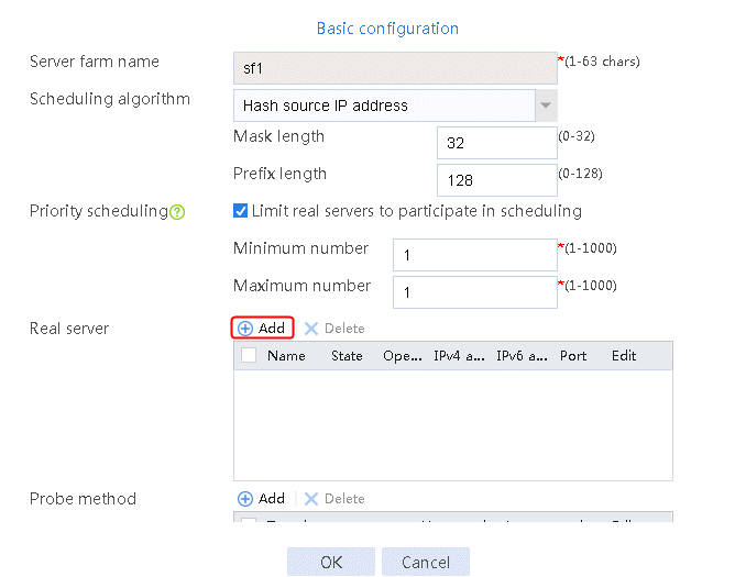
Figure 162 Creating a real server

3. Click OK.
4. Create real servers rs2 and rs3 in the same way rs1 is created. Specify the priority of rs2 as 8 and the IPv4 address as 192.168.1.2. Specify the priority of rs3 as 1 and the IPv4 address as 192.168.1.3.
Figure 163 Server farm information

Configuring a virtual server
1. Navigate to the LB > Application Load Balancing > Virtual Servers page.
2. Click Create to create a virtual server named vs, specify the type as HTTP, virtual server IP address as 61.159.4.100, default server farm as sf1, and enable the virtual server feature.
Figure 164 Creating a virtual server
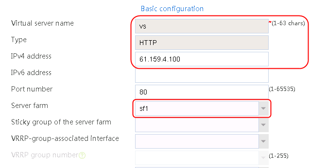

3. Click OK.
Verifying the configuration
Sending an FTP request
When number of servers available for scheduling is set to 1, send an FTP request from the host to the FTP server with IP address 61.159.4.100. After the access is successful, you can view the virtual server and real server statistics on the LB device. Real server rs2 with the highest priority is selected, and statistics for only real server rs2 is displayed.
Figure 165 Virtual server statistics

Figure 166 Real server statistics
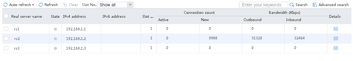
When number of servers available for scheduling is set to 2, send an FTP request from the host to the FTP server with IP address 61.159.4.100. After the access is successful, you can view the virtual server and real server statistics on the LB device. The traffic is distributed to rs1 and rs2 with higher priorities.
Figure 167 Virtual server statistics
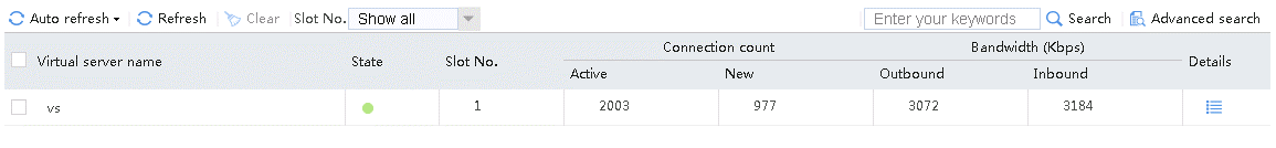
Figure 168 Real server statistics

Configuration files
#
nqa template http t1
expect status 200
#
server-farm sf1
predictor hash address source
selected-server min 1 max 1
probe t1
success-criteria at-least 1
real-server rs1 port 0
success-criteria at-least 1
real-server rs2 port 0
priority 8
success-criteria at-least 1
real-server rs3 port 0
priority 1
success-criteria at-least 1
#
real-server rs1
ip address 192.168.1.1
#
real-server rs2
ip address 192.168.1.2
#
real-server rs3
ip address 192.168.1.3
#
virtual-server vs type http
virtual ip address 61.159.4.100
default server-farm sf1
sticky-sync enable global
service enable
#
Example: Configuring client source address insertion
Network configuration
The SNAT service is deployed for SLB. Enable the LB device to insert specific values in the client requests for the server to perform data statistics based on the client address.
As shown in the Figure 169, the internal host can access three servers through the LB device. The three servers Server A, Server B, and Server C in the public network can all provide HTTP services. The host requests to the server will be load-shared among the three servers. Configure the LB device to perform SNAT on the host requests, and transparently transmit the client address with the URL keyword government in the access requests to the real server C for further processing. Other access requests are load-shared between real servers A and B.

Analysis
To enable the LB device to transparently transmit the client source address of a specific user, complete the following configuration on the LB device:
· Configure SNAT to shield the internal network address of the client.
· Create an LB policy. In the LB action, enable X-Forwarded-For field insertion to carry the client source address upon receiving access requests containing keyword government in the URL. The LB device will directly load-share other requests.
· Create an HTTP parameter profile, enable per-request load balancing to insert a source address into each client request.
Software versions used
This configuration example was created and verified on Alpha 1160P16 of L1000-AK315.
Restrictions and guidelines
When you configure client source address insertion, follow these restrictions and guidelines:
· Make sure a route is available from the host to the LB device.
· Specify the real server addresses on the LB device as the actual server addresses.
· When the IP addresses in the SNAT address pool are in the same network segment as the outbound interface, specify the interface in the address pool for sending gratuitous ARP packets.
· The header content in an HTTP packet is a string of 1 to 255 characters. You can also specify the following replacement strings:
¡ %is—Source IP address or source IPv6 address.
¡ %ps—Source port number.
¡ %id—Destination IP address or destination IPv6 address.
¡ %pd—Destination port number.
Procedures
Perform the following configuration on the LB device.
Assigning IP addresses to interfaces
Details not shown.
Creating a health monitoring template
1. Navigate to the LB > Global Configuration > Health Monitoring page.
2. Click Create to create a template named t1, specify the type as HTTP, and set the expected status code to 200.
Figure 170 Creating a health monitoring template
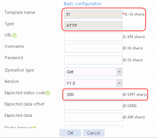
3. Click OK.
Creating an SNAT address pool
1. Navigate to the LB > Global Configuration > SNAT Pool page.
2. Click Create to create an SNAT pool named snat1. Set both the start and end IP addresses to public network address 192.168.1.254. Specify the interface for sending gratuitous ARP or ND packets.
Figure 171 Creating an SNAT pool
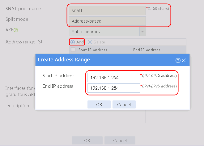
3. Click OK.
Figure 172 SNAT pool information
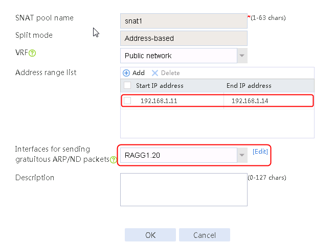
4. Click OK.
Configuring a server farm
1. Navigate to the LB > Application Load Balancing > Server Farms page. Click Create to create a server farm named sf1. Specify the scheduling algorithm as Hash source IP address, probe method as t1, and SNAT address pool as snat1.
Figure 173 Creating server farm sf1


2. Click OK.
3. Navigate to the LB > Application Load Balancing > Server Farms page to create a server farm named sf2. Specify the scheduling algorithm as Round robin, probe method as t1, SNAT address pool as snat1, and then click OK.
Figure 174 Creating server farm sf2
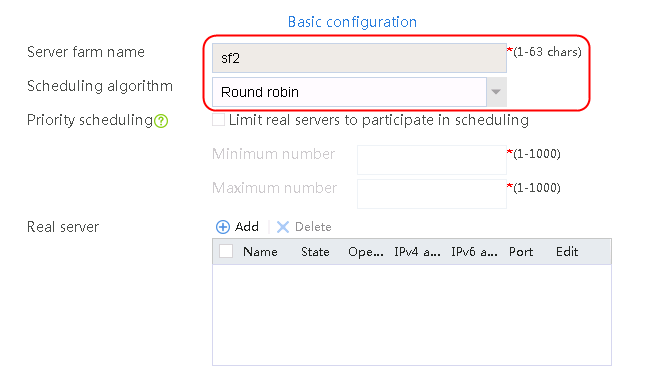
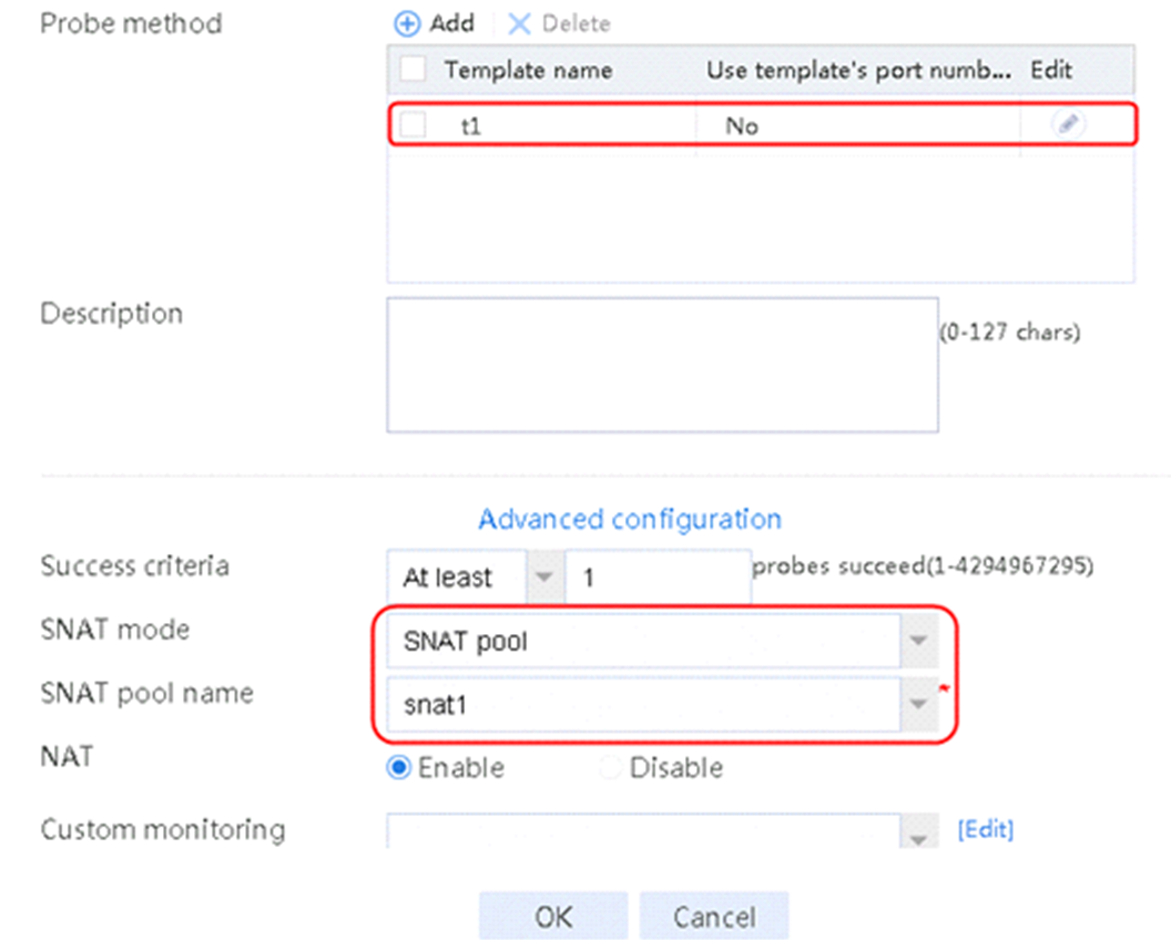
Configuring real servers
1. Navigate to the LB > Application Load Balancing > Server Farms page.
2. Edit server farm sf1, and add a real server. Create a real server named rs1, specify the real server IP address as 192.168.1.1, and click OK.
Figure 175 Adding a real server

Figure 176 Creating a real server

3. Click OK.
4. Create real server rs2 in the same way rs1 is created:
a. Navigate to the LB > Application Load Balancing > Server Farms page.
b. Edit server farm sf1 to add a real server.
c. Create real server rs2 as shown in the figure above, and configure its IPv4 address as 192.168.1.2.
5. Create real server rs3 in the same way rs1 is created:
a. Navigate to the LB > Application Load Balancing > Server Farms page.
b. Edit server farm sf2 to add a real server.
c. Create real server rs3 as shown in the figure above, and configure its IPv4 address as 192.168.1.2.
Figure 177 Server farm information
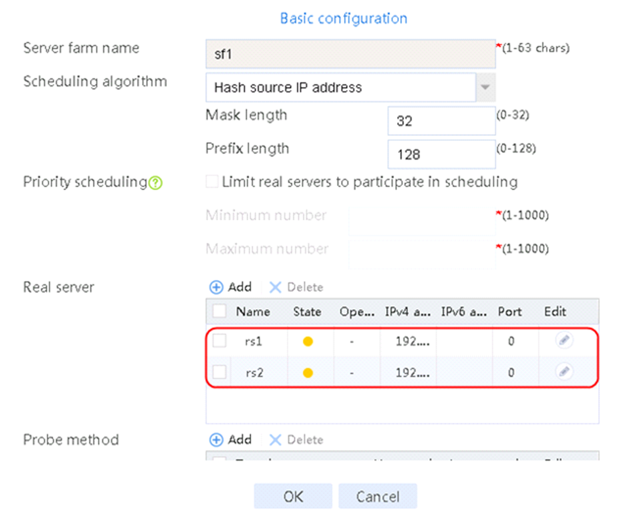
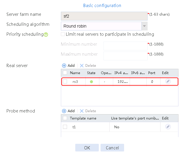
Creating an LB class
1. Navigate to the LB > Application Load Balancing > Advanced Policies > Classes page.
2. Create an LB class of the HTTP type named lc1 to match access requests containing keyword government in the URL.
Figure 178 Creating an LB class

3. Click OK.
Figure 179 Class information

Creating an LB action
1. Navigate to the LB > Application Load Balancing > Advanced Policies > Actions page.
2. Create an LB action of the HTTP type named la1 to forward matching traffic to server farm sf2, and enable X-Forwarded-For field insertion.
Figure 180 Creating an LB action

3. Navigate to the LB > Application Load Balancing > Advanced Policies > Actions page to create an LB action of the HTTP type named la2 to forward matching traffic to server farm sf1.
Figure 181 Creating an LB action

Creating an LB policy
1. Navigate to the LB > Application Load Balancing > Advanced Policies > LB Policies page.
2. Create an LB policy of the HTTP type named lp1, and specify the default action as la2. In the Create Rule dialog box, specify LB class lc1 and LB action la1.
Figure 182 Creating a policy

3. Click OK.
Figure 183 Policy information

Configuring a parameter profile
1. Navigate to the LB > Application Load Balancing > Parameter Profiles page.
2. Click Create to create an HTTP parameter profile named pp1, and enable Load balance each request.
Figure 184 Creating a parameter profile
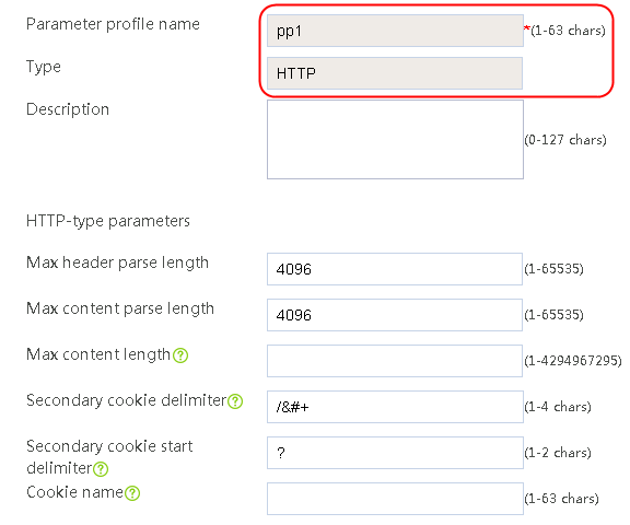
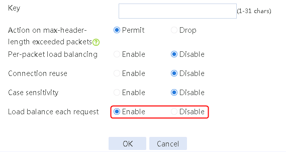
Configuring a virtual server
1. Navigate to the LB > Application Load Balancing > Virtual Servers page.
2. Click Create to create a virtual server named vs. Specify the type as HTTP and the virtual IP address as 61.159.4.100. Specify LB policy lp1 and parameter profile pp1, and enable the virtual server feature.
Figure 185 Creating a virtual server

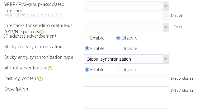

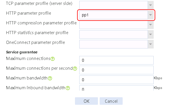
Verifying the configuration
The host initiates a request without keyword government in the URL to access the HTTP server through http://61.159.4.100. The access is successful. The request is assigned to real servers rs1 and rs2 of server farm sf1. View the both virtual server and real server statistics.
Figure 186 Virtual server statistics
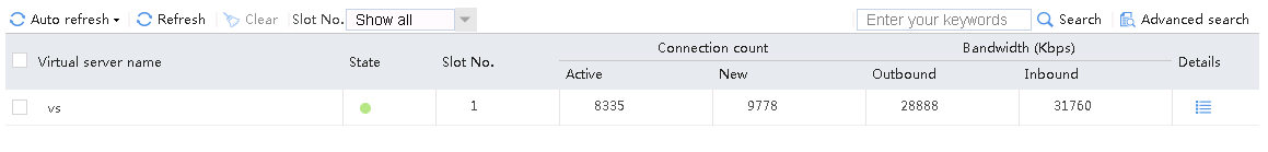
Figure 187 Real server statistics
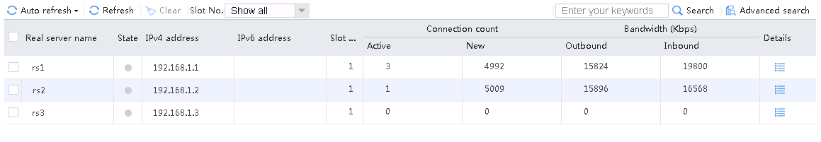
The host initiates a request that contains keyword government in the URL to access the HTTP server through http://61.159.4.100. The access is successful. You can see that the request containing keyword government in the URL is assigned to rs3. The packet capture information on the server shows that the request header contains the x-forwarded-for field whose value is the client address. View the virtual server and real server statistics as well as the packet capture information.
Figure 188 Virtual server statistics

Figure 189 Real server statistics
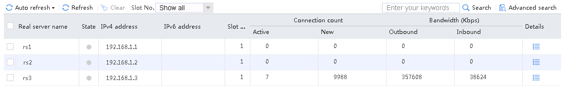
A large number of hosts access the HTTP server through http://61.159.4.100. The accesses are successful. From the packet capture information on the server, you can see the requests containing keyword government in the URL. The request header contains the x-forwarded-for field whose value is the client address.
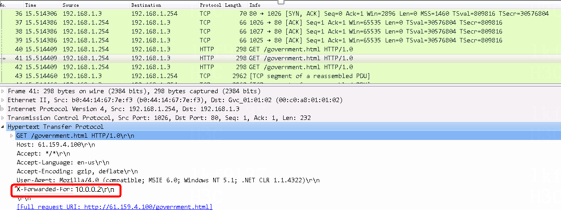
Configuration files
#
nqa template http t1
expect status 200
#
loadbalance snat-pool snat1
ip range start 192.168.1.254 end 192.168.1.254
arp-nd interface Route-Aggregation1.20
#
server-farm sf1
predictor hash address source
snat-pool snat1
probe t1
success-criteria at-least 1
real-server rs1 port 0
success-criteria at-least 1
real-server rs2 port 0
success-criteria at-least 1
#
server-farm sf2
snat-pool snat1
probe t1
success-criteria at-least 1
real-server rs3 port 0
success-criteria at-least 1
#
loadbalance class lc1 type http
match 1 url government
#
loadbalance action la1 type http
server-farm sf2
header insert request name X-Forwarded-For value %is
#
loadbalance action la2 type http
server-farm sf1
#
loadbalance policy lp1 type http
class lc1 action la1
default-class action la2
#
real-server rs1
ip address 192.168.1.1
#
real-server rs2
ip address 192.168.1.2
#
real-server rs3
ip address 192.168.1.3
#
parameter-profile pp1 type http
header modify per-request
#
virtual-server vs type http
virtual ip address 61.159.4.100
parameter http pp1
lb-policy lp1
sticky-sync enable global
service enable
#
Example: Configuring NAT66 client source address insertion
Network configuration
The SNAT service is deployed for SLB. Enable the LB device to insert specific values in the client requests for the server to perform data statistics based on the client address.
As shown in the Figure 190, the internal user Host can access three servers through the LB device. The three servers Server A, Server B, and Server C in the public network can all provide HTTP services. The host requests to the server will be load-shared among the three servers. Configure the LB device to perform SNAT on the host requests, and transparently transmit the client address with the URL keyword government in the access requests to the real server C for further processing. Other access requests are load-shared between real servers A and B.
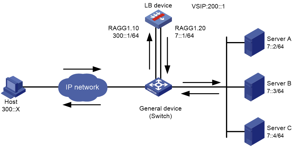
Analysis
To enable the LB device to transparently transmit the client source address of a specific user, complete the following configuration on the LB device:
· Configure SNAT to shield the internal network address of the client.
· Create an LB policy. In the LB action, enable X-Forwarded-For field insertion to carry the client source address upon receiving access requests containing keyword government in the URL. The LB device will directly load-share other requests.
· Create an HTTP parameter profile, enable per-request load balancing to insert a source address into each client request.
Software versions used
This configuration example was created and verified on Alpha 1160P16 of L1000-AK315.
Restrictions and guidelines
When you configure NAT66 client source address insertion, follow these restrictions and guidelines:
· Make sure a route is available from the host to the LB device.
· Specify the real server addresses on the LB device as the actual server addresses.
· The header content in an HTTP packet is a string of 1 to 255 characters. You can also specify the following replacement strings:
¡ %is—Source IP address or source IPv6 address.
¡ %ps—Source port number.
¡ %id—Destination IP address or destination IPv6 address.
¡ %pd—Destination port number.
¡ %sps—Source port number on the server end.
¡ %spd—Destination port number on the server end.
¡ %sis—Source IP address on the server end.
¡ %sid—Destination IP address on the server end.
Procedures
Perform the following configuration on the LB device.
Assigning IP addresses to interfaces
Details not shown.
Creating a health monitoring template
1. Navigate to the LB > Global Configuration > Health Monitoring page.
2. Click Create to create a template named t1, specify the type as HTTP, and set the expected status code to 200.
Figure 191 Creating a health monitoring template

3. Click OK.
Creating an SNAT address pool
1. Navigate to the LB > Global Configuration > SNAT Pool page.
2. Click Create to create an SNAT pool named snat1. Set both the start and end addresses to public network address of 7::6. Specify the interface for sending gratuitous ARP or ND packets.
Figure 192 Creating an SNAT pool
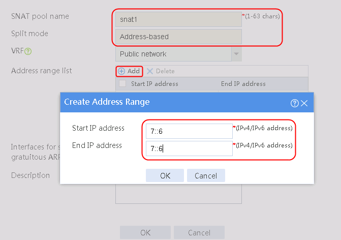
3. Click OK.
Figure 193 SNAT pool information
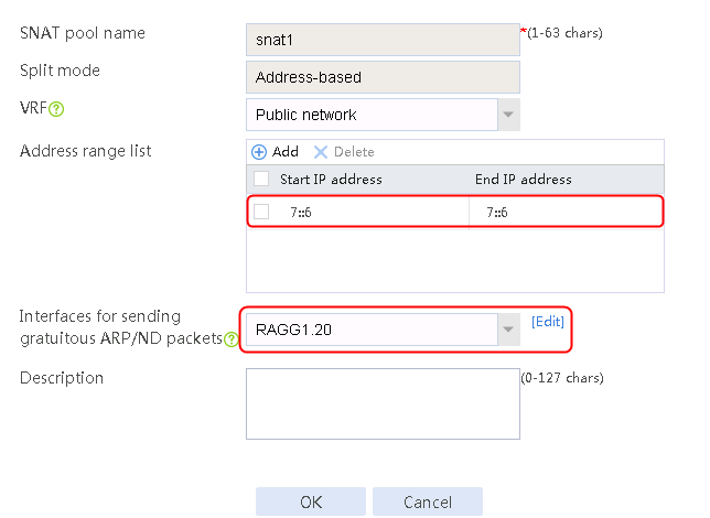
4. Click OK.
Configuring a server farm
1. Navigate to the LB > Application Load Balancing > Server Farms page.
2. Click Create to create a server farm named sf1. Specify the scheduling algorithm as Hash source IP address, probe method as t1, and SNAT address pool as snat1.
Figure 194 Creating server farm sf1


3. Click OK.
4. Navigate to the LB > Application Load Balancing > Server Farms page to create a server farm named sf2. Specify the scheduling algorithm as Round robin, probe method as t1, SNAT address pool as snat1, and then click OK.
Figure 195 Creating server farm sf2


Configuring real servers
1. Navigate to the LB > Application Load Balancing > Server Farms page.
2. Edit server farm sf1, and add a real server. Create a real server named rs1, specify its IP address as 7::2, and then click OK.
Figure 196 Adding a real server

Figure 197 Creating a real server
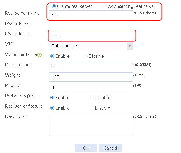
3. Click OK.
4. Create a real server named rs2 for server farm sf1 as shown in the figure above and configure its IPv6 address as 7::3.
5. Create a real server named rs3 for server farm sf2 as shown in the figure above and configure its IPv6 address as 7::4.
Figure 198 Server farm information
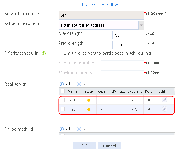
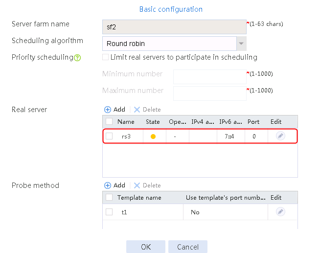
Creating an LB class
1. Navigate to the LB > Application Load Balancing > Advanced Policies > Classes page.
2. Create an LB class of the HTTP type named lc1 to match access requests containing keyword government in the URL.
Figure 199 Creating a class
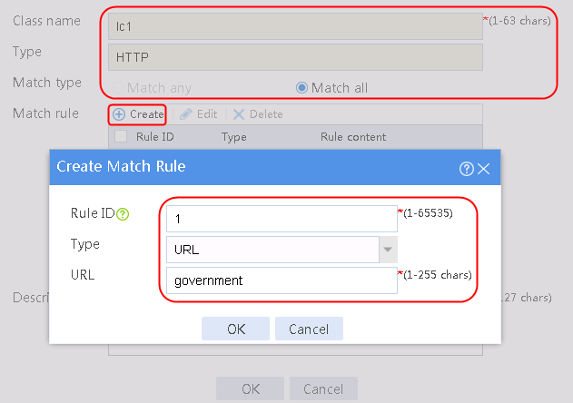
3. Click OK.
Figure 200 Class information
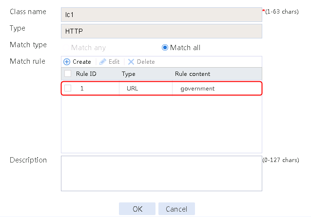
Creating an LB action
1. Navigate to the LB > Application Load Balancing > Advanced Policies > Actions page.
2. Create an LB action of the HTTP type named la1 to forward matching traffic to server farm sf2, and enable X-Forwarded-For field insertion.
Figure 201 Creating an LB action
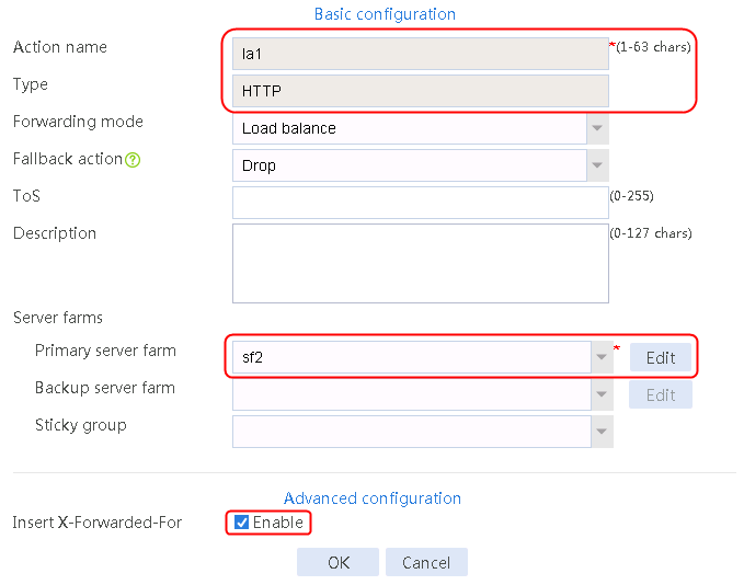
3. Navigate to the LB > Application Load Balancing > Advanced Policies > Actions page to create an LB action of the HTTP type named la2 to forward matching traffic to server farm sf1.
Figure 202 Creating an LB action

Creating an LB policy
1. Navigate to the LB > Application Load Balancing > Advanced Policies > LB Policies page.
2. Create an LB policy of the HTTP type named lp1, and specify the default action as la2. In the Create Rule dialog box, specify LB class lc1 and LB action la1.
Figure 203 Creating a policy
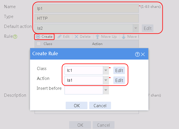
3. Click OK.
Figure 204 Policy information
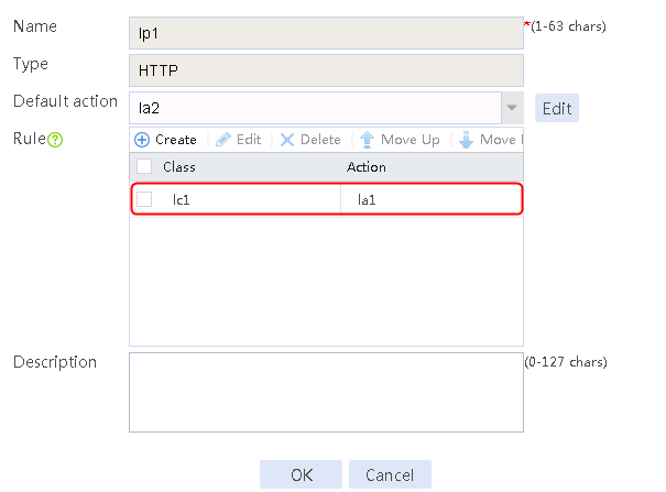
Configuring a parameter profile
1. Navigate to the LB > Application Load Balancing > Parameter Profiles page.
2. Click Create to create an HTTP parameter profile named pp1, and enable Load balance each request.
Figure 205 Creating a parameter profile


Configuring a virtual server
1. Navigate to the LB > Application Load Balancing > Virtual Servers page.
2. Click Create to create a virtual server named vs. Specify the type as HTTP and virtual IP address as 200::1. Specify LB policy lp1 and parameter profile pp1, and enable the virtual server feature.
Figure 206 Creating a virtual server
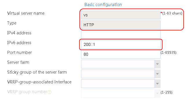


Verifying the configuration
A large number of hosts access the HTTP server through http://200::1. The accesses are successful. From the packet capture information on the server, you can see the requests containing keyword government in the URL. The request header contains the x-forwarded-for field whose value is the client address.
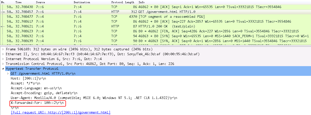
Configuration files
#
nqa template http t1
expect status 200
#
loadbalance snat-pool snat1
ipv6 range start 7::6 end 7::6
arp-nd interface Route-Aggregation1.20
#
server-farm sf1
predictor hash address source
snat-pool snat1
probe t1
success-criteria at-least 1
real-server rs1 port 80
success-criteria at-least 1
real-server rs2 port 80
success-criteria at-least 1
#
server-farm sf2
snat-pool snat1
probe t1
success-criteria at-least 1
real-server rs3 port 80
success-criteria at-least 1
#
loadbalance class lc1 type http
match 1 url government
#
loadbalance action la1 type http
server-farm sf2
header insert request name x-forwarded-for value %is
#
loadbalance action la2 type http
server-farm sf1
#
loadbalance policy lp type http
class lc1 action la1
default-class action la2
#
real-server rs1
ipv6 address 7::2
#
real-server rs2
ipv6 address 7::3
#
real-server rs3
ipv6 address 7::4
#
parameter-profile pp1 type http
header modify per-request
#
virtual-server vs type http
virtual ipv6 address 200::1
parameter http pp1
lb-policy lp1
sticky-sync enable global
service enable
#
Example: Configuring URL-based HTTP redirection
Network configuration
A host accesses three servers Server A, Server B, and Server C through the LB device. Configured with the HTTP and HTTPS protocols, the servers in the public network can all provide HTTP services. The host requests to the server will be load-shared among the three servers.
Configure HTTP redirection actions based on URLs in host requests to redirect an HTTP request to an HTTPS request or redirect an HTTPS request to an HTTP request. For example:
· When a request contains HTTP URL http://61.159.4.100/login/index.html, the LB device redirects it to HTTPs URL https://61.159.4.100/login/index.html.
· When a request contains HTTPS URL https://61.159.4.100/map/index.html, the LB device redirects it to HTTP URL http://61.159.4.100/map/index.html.
Figure 207 Network diagram

Analysis
To implement URL-based HTTP redirection, complete the following configuration on the LB device:
· Configure server farm, real server, and LB policy settings.
· Import the CA and local certificates to the LB device, and create an SSL policy on the LB device.
· Configure virtual server settings and apply LB policies to the virtual server.
· Configure LB actions to redirect an HTTP request to an HTTPS request or redirect an HTTPS request to an HTTP request according to the requested URLs.
Software versions used
This configuration example was created and verified on Feature 1160P16 of L1070.
Restrictions and guidelines
When you configure the URL-based policy redirection function, follow these restrictions and guidelines:
· Make sure a route is available from the host to the LB device.
· Make sure the real server associated with the HTTPS virtual server uses port number 80.
· After configuring the virtual server, you need to enable the virtual server feature.
· After creating an SSL server policy, use relevant commands to manually enable the SSL server to send the complete certificate chain during SSL negotiation.
Procedures
Perform the following configuration on the LB device.
Assigning IP addresses to interfaces
Details not shown.
Creating a health monitoring template
1. Navigate to the LB > Global Configuration > Health Monitoring page.
2. Click Create to create a template named t1, specify the type as HTTP, and set the expected status code to 200.
Figure 208 Creating a health monitoring template

3. Click OK.
Creating a server farm
1. Navigate to the LB > Application Load Balancing > Server Farms page.
2. Click Create to create a server farm named sf1. Specify the scheduling algorithm as Hash source IP address and probe method as t1.
Figure 209 Creating a server farm


3. Click OK.
Configuring real servers
1. Navigate to the LB > Application Load Balancing > Server Farms page.
2. Edit server farm sf1, and click Add to create a real server. Specify the real server name as rs1, the IP address as 192.168.1.1, and the port number as 80.
Figure 210 Adding a real server

Figure 211 Creating a real server
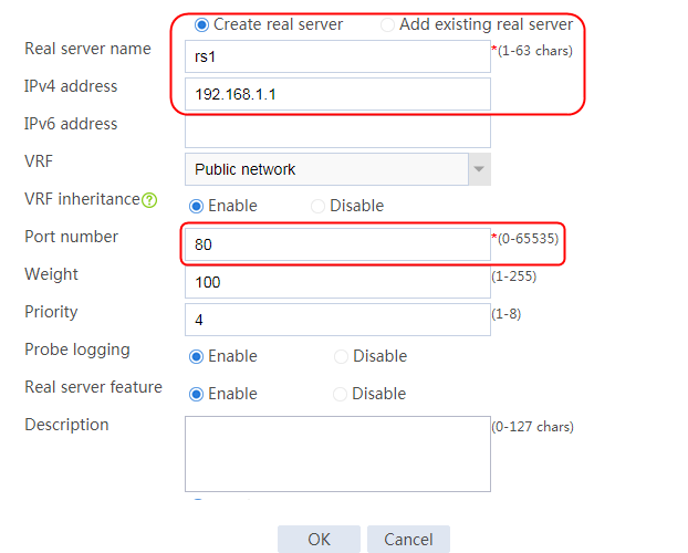
3. Click OK.
4. Create real servers rs2 and rs3 in the same way rs1 is created. Configure IPv4 addresses as 192.168.1.2 and 192.168.1.3 and port number as 80 for real servers rs2 and rs3, respectively.
Figure 212 Server farm information
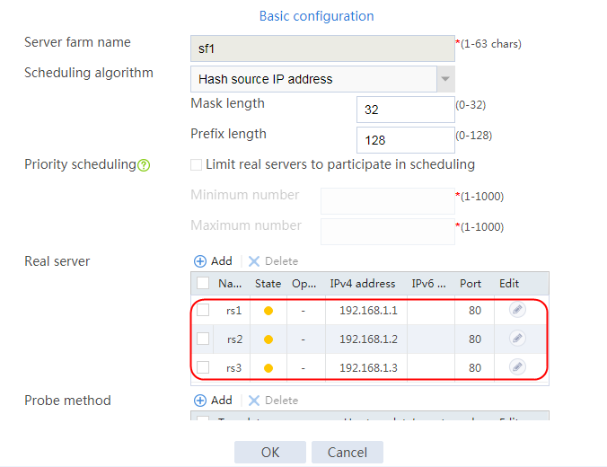
Configuring LB classes
1. Navigate to the LB > Application Load Balancing > Advanced Policies > Classes page.
2. Create a class named lc-http. In the Create Match Rule dialog box, set the rule ID to 1, the type to URL, and the URL to /login.
Figure 213 Creating a class named lc-http
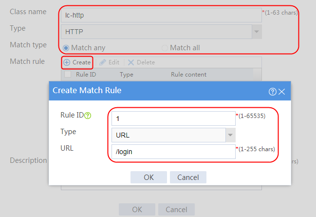
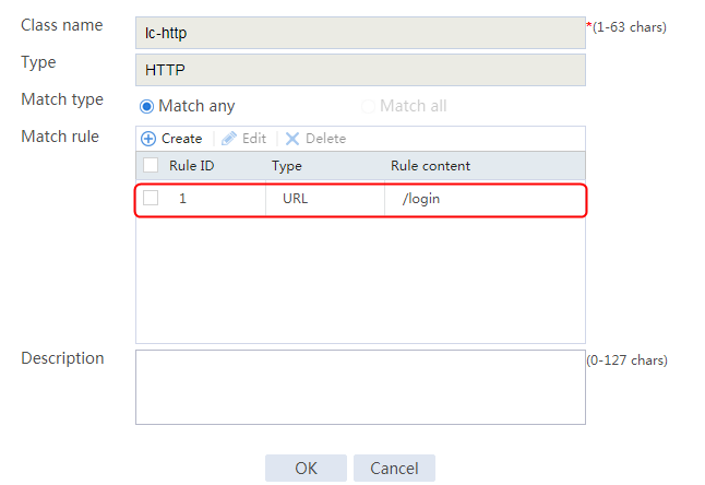
3. Create a class named lc-https. In the Create Match Rule dialog box, set the rule ID to 1, the type to URL, and the URL to /map.
Figure 214 Creating a class named lc-https

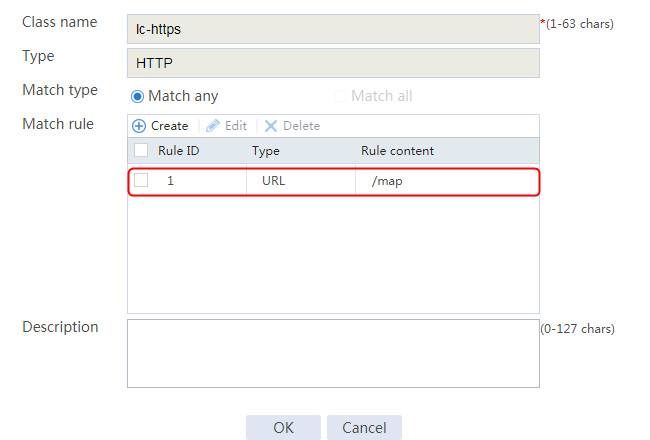
Configuring LB actions
1. Navigate to the LB > Application Load Balancing > Advanced Policies > Actions page.
2. Create an action named http-https, specify the type as HTTP redirection, and specify the redirection URL as https://%h%p.
Figure 215 Creating an action
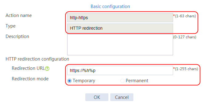
3. Navigate to the LB > Application Load Balancing > Advanced Policies > Actions page.
4. Create an action named https-http, specify the type as HTTP redirection, and specify the redirection URL as http://%h%p.
Figure 216 Creating an action
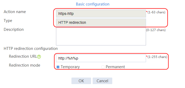
Configuring an LB policy
1. Navigate to the LB > Application Load Balancing > Advanced Policies > LB Policies page.
2. Create an LB policy named lp1, and specify the type as HTTP. In the Create Rule dialog box, specify class lc-http and action http-https.
Figure 217 Creating LB policy lp1
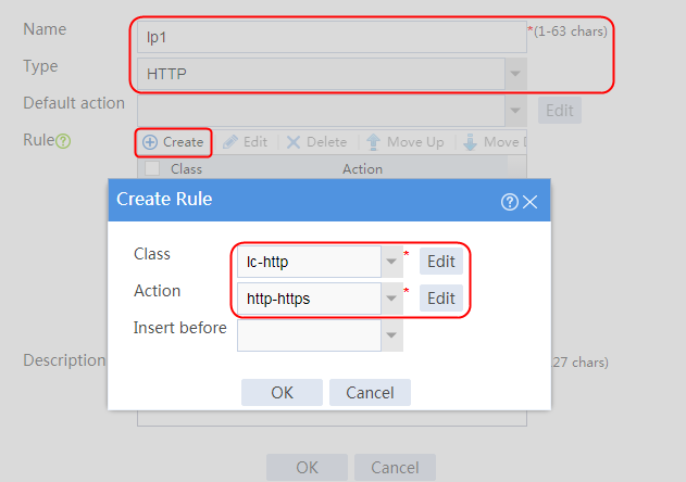
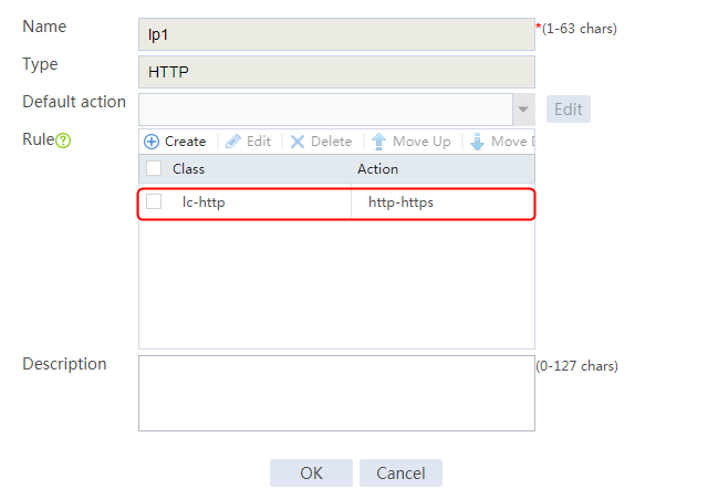
3. Navigate to the LB > Application Load Balancing > Advanced Policies > LB Policies page.
4. Create an LB policy named lp1, and specify the type as HTTP. In the Create Rule dialog box, specify class lc-https and action https-http.
Figure 218 Creating LB policy lp2
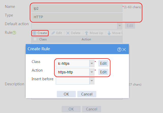
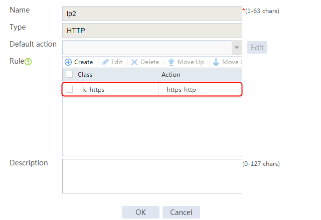
Creating a PKI domain and disabling CRL checking
1. Navigate to the Objects > KPI > Certificates page.
2. Click Create to create a PKI domain named ca, and disable CRL checking.
Figure 219 Creating a PKI domain

3. Click OK.
Importing the CA certificate and local certificate
1. Select the created PKI domain ca, and click Import Certificate.
Figure 220 Importing a certificate

2. Specify the certificate type as CA certificate, and click Select file to select the CA certificate file.
Figure 221 Importing a CA certificate
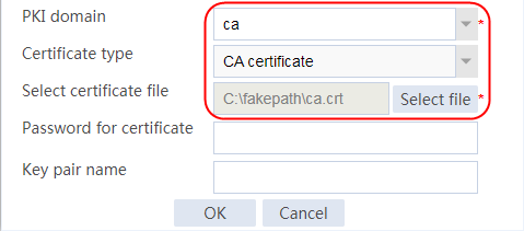
3. Click OK and then click Yes to confirm the fingerprint information.
Figure 222 Certificate fingerprint information
4. Specify the certificate type as Local certificate, click Select file to select the local certificate file, and enter the certificate password.
Figure 223 Importing a local certificate

5. Click OK.
Creating an SSL server policy and specifying PKI domain ca
1. Navigate to the Objects > SSL > Server Policies page.
2. Click Create to create an SSL server policy named SSL, and specify the PKI domain as ca.
Figure 224 Creating an SSL server policy

3. Click OK.
4. Execute the following commands to manually enable the SSL server to send a complete certificate chain during SSL negotiation (the configuration is not supported on the Web interface):
[Sysname] ssl server-policy ssl
[Sysname-ssl-server-policy-ssl] certificate-chain-sending enable
Configuring a virtual server
1. Navigate to the LB > Application Load Balancing > Virtual Servers page.
2. Create a virtual server named vs1. Specify the type as HTTP, IPv4 address as 61.159.4.100, default server farm as sf1, and port number as 80. Specify LB policy lp1, enable the virtual server feature, and then click OK.
Figure 225 Creating virtual server vs1
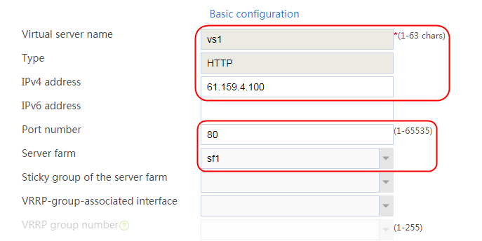


3. Click OK.
4. Navigate to the LB > Application Load Balancing > Virtual Servers page to create a virtual server named vs2. Specify the type as HTTPS, IPv4 address as 61.159.4.100, default server farm as sf1, and port number as 443. Specify SSL server policy ssl, specify LB policy lp2, and enable the virtual server feature.
Figure 226 Creating virtual server vs2
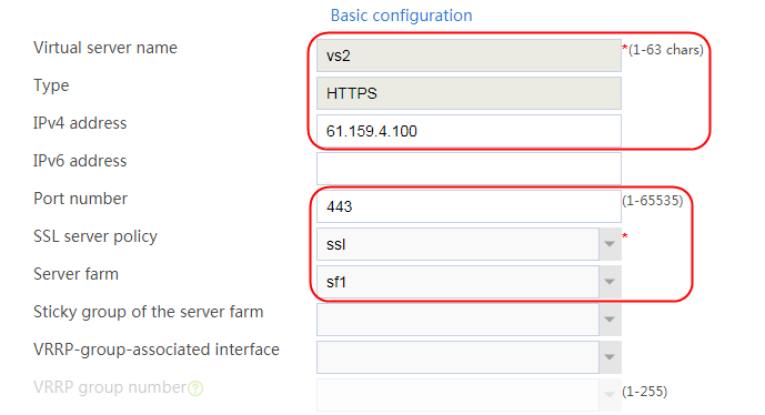

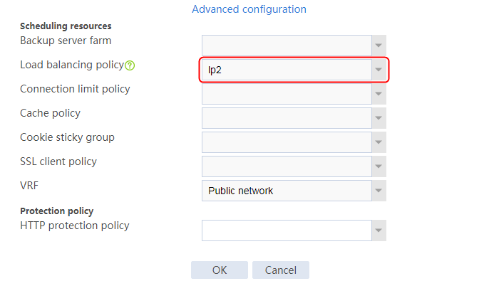
5. Click OK.
Verifying the configuration
Redirecting http://x.x.x.x/login in the request to https://x.x.x.x/login
If you enter http://61.159.4.100/login/index.html, the URL will be redirected to https://61.159.4.100/login/index.html.
Figure 227 Captured packets on the host
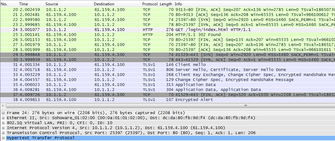
Redirecting https://x.x.x.x/map/index.html in the request to http://x.x.x.x/map.html
If you enter https://61.159.4.100/map/index.html, the URL will be redirected to http://61.159.4.100/login/index.html.
Figure 228 Captured packets on the host

Configuration files
#
#
nqa template http t1
expect status 200
#
pki domain ca
public-key rsa general name ca
undo crl check enable
#
ssl server-policy ssl
pki-domain ca
ciphersuite dhe_rsa_aes_256_cbc_sha rsa_aes_256_cbc_sha dhe_rsa_aes_128_cbc_sha
rsa_aes_128_cbc_sha rsa_aes_128_cbc_sha256 rsa_aes_256_cbc_sha256 dhe_rsa_aes_1
28_cbc_sha256 dhe_rsa_aes_256_cbc_sha256 ecdhe_rsa_aes_128_cbc_sha256 ecdhe_rsa_
aes_256_cbc_sha384 ecdhe_rsa_aes_128_gcm_sha256
ciphersuite ecdhe_rsa_aes_256_gcm_sha384 ecdhe_ecdsa_aes_128_cbc_sha256 ecdhe_e
cdsa_aes_256_cbc_sha384 ecdhe_ecdsa_aes_128_gcm_sha256 ecdhe_ecdsa_aes_256_gcm_s
ha384 tls_aes_128_gcm_sha256 tls_aes_256_gcm_sha384 tls_chacha20_poly1305_sha256
tls_aes_128_ccm_sha256 tls_aes_128_ccm_8_sha256
certificate-chain-sending enable
version ssl3.0 disable
version tls1.0 disable
#
server-farm sf1
predictor hash address source
probe t1
success-criteria at-least 1
real-server rs1 port 80
success-criteria at-least 1
real-server rs2 port 80
success-criteria at-least 1
real-server rs3 port 80
success-criteria at-least 1
#
loadbalance class lc-http type http match-any
match 1 url /login
#
loadbalance class lc-https type http match-any
match 1 url /map
#
loadbalance action http-https type http
redirect relocation https://%h%p
#
loadbalance action https-http type http
redirect relocation http://%h%p
#
loadbalance policy lp1 type http
class lc-http action http-https
#
loadbalance policy lp2 type http
class lc-https action https-http
#
real-server rs1
ip address 192.168.1.1
#
real-server rs2
ip address 192.168.1.2
#
real-server rs3
ip address 192.168.1.3
#
virtual-server vs1 type http
virtual ip address 61.159.4.100
lb-policy lp1
default server-farm sf1
sticky-sync enable global
service enable
#
virtual-server vs2 type http
port 443
virtual ip address 61.159.4.100
lb-policy lp2
default server-farm sf1
ssl-server-policy ssl
sticky-sync enable global
service enable
#
Example: Configuring content rewrite for HTTP redirection
Network configuration
A host accesses four servers through the LB device. The four servers can provide HTTP services. One group of servers provide HTTP services via port 8080, and the other group provide HTTP services via port 80. Configure the LB device to rewrite the URL in the Location header of HTTP response packets according to different user requests. The LB devices load-shares host traffic among the four servers, and provides port 80 to the user.
Configure the redirection feature for the real servers to implement the following requirements:
· When the URL in the request is /test1, the redirection URL is server IP + server port.
· When the URL in the request is /test2, the redirection URL is virtual server IP + server port.
· When the URL in the request is /test3, the redirection URL is domain name + server port.
· The LB device replaces the Location header value in the response packets with virtual server IP + virtual server port and sends them to the user.
Figure 229 Network diagram
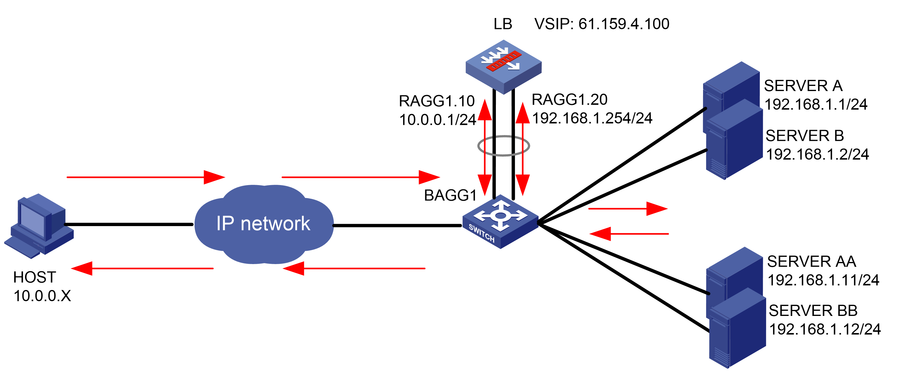
Analysis
For user requests containing URL test1, the three real servers respond with the redirection URL http://RS_IP:8080/. For user requests containing URL test2, the three real servers respond with the redirection URL http://VIP :8080/. For user requests containing URL test3, the three real servers respond with the redirection URL http://HOST:8080/. The LB device replaces the Location header value in the response packets with http://VIP/. When the user initiate a request with this URL, the real servers can respond with an OK packet correctly.
This configuration example does not illustrate how to configure the redirection feature for real servers.
To modify the Location header in the response packets sent from real servers, complete the following configuration on the LB device:
· Configure server farm and real server settings.
· Configure an LB policy to match URLs containing test1, test2, or test3 and URLs that do not carry these strings. Configure LB actions to replace the Location header content in the response packets sent from real servers.
· Configure a virtual server and apply the LB policy to the virtual server.
Software versions used
This configuration example was created and verified on Feature 1160P16 of L1070.
Restrictions and guidelines
When you configure the content rewrite for HTTP redirection, follow these restrictions and guidelines:
· Make sure a route is available from the host to the LB device.
· Make sure the port number used by the real server is 8080.
· After configuring the virtual server, you need to enable the virtual server feature.
Procedures
Perform the following configuration on the LB device.
In this example, two real servers can respond with redirection or 200 OK packets. You can enable the feature on one real server as needed.
Assigning IP addresses to interfaces
Details not shown.
Creating an HTTP NQA template
1. Navigate to the LB > Global Configuration > Health Monitoring page.
2. Click Create to create a template named t1, specify the type as HTTP, and set the expected status code to 200.
Figure 230 Creating a health monitoring template named t1

3. Click OK.
Configuring server farms
1. Navigate to the LB > Application Load Balancing > Server Farms page.
2. Click Create to create a server farm named sf1. Specify the scheduling algorithm as Hash source IP address and probe method as t1.
Figure 231 Creating a server farm

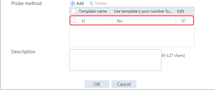
3. Click OK.
4. Create server farm sf2 in the same way sf1 is created. Use server farm sf2 to distribute reinitiated client requests according to the redirection content.
Configuring real servers
1. Navigate to the LB > Application Load Balancing > Server Farms page.
2. Edit server farm sf1, and click Add to create a real server. Specify the real server name as rs1, IP address as 192.168.1.1, and port number as 8080.
Figure 232 Adding a real server
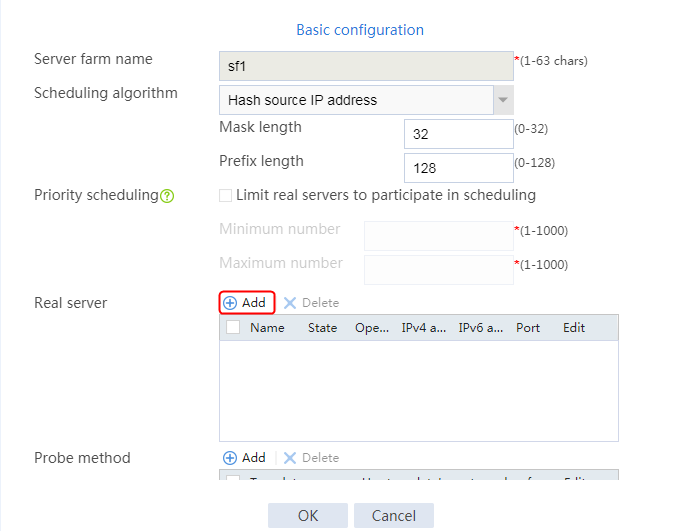
Figure 233 Creating a real server
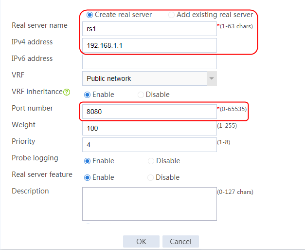
3. Click OK.
4. Create real server rs2 in the same way rs1 is created:
a. Navigate to the LB > Application Load Balancing > Server Farms page.
b. Edit server farm sf2 to add a real server.
c. Create real server rs2 as shown in the figure above. Configure its IPv4 address as 192.168.1.2 and port number as 8080.
5. Create real servers rs11 and rs12 in the same way rs1 is created:
a. Navigate to the LB > Application Load Balancing > Server Farms page.
b. Edit server farm sf2 to add a real server.
c. Create real servers rs11 and rs12 as shown in the figure above. Configure their IPv4 addresses as 192.168.1.11 and 192.168.1.12 and port number as 80.
Figure 234 Server farm information
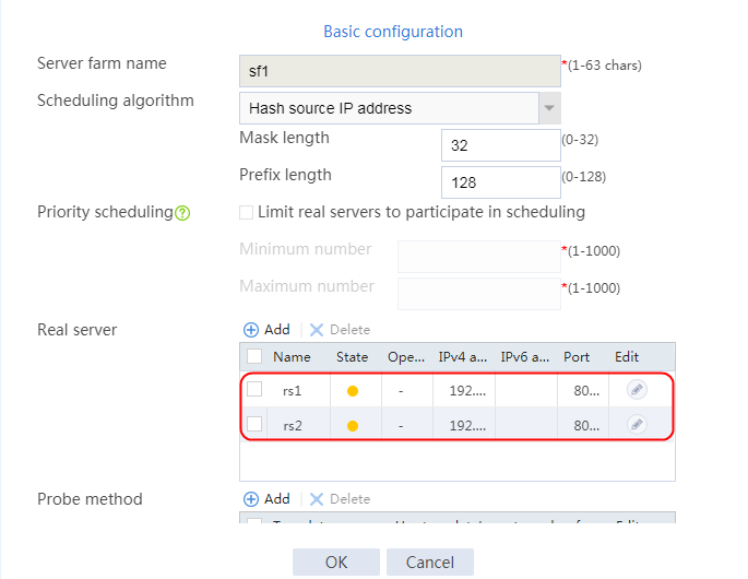
Configuring an LB class
1. Navigate to the LB > Application Load Balancing > Advanced Policies > Classes page.
2. Create a class named lc1, and specify the type as HTTP and the match type as Match any.
3. Click Create to create match rules 1, 2, and 3 to match URL content test1, test2, and test3, respectively.
Figure 235 Creating a class
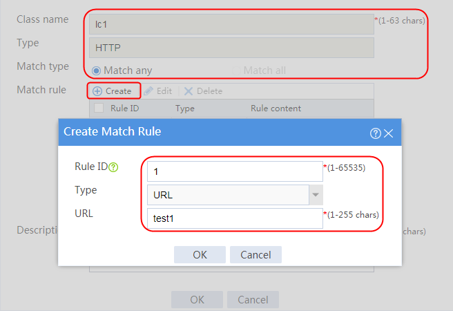
Figure 236 Parameters of class lc1
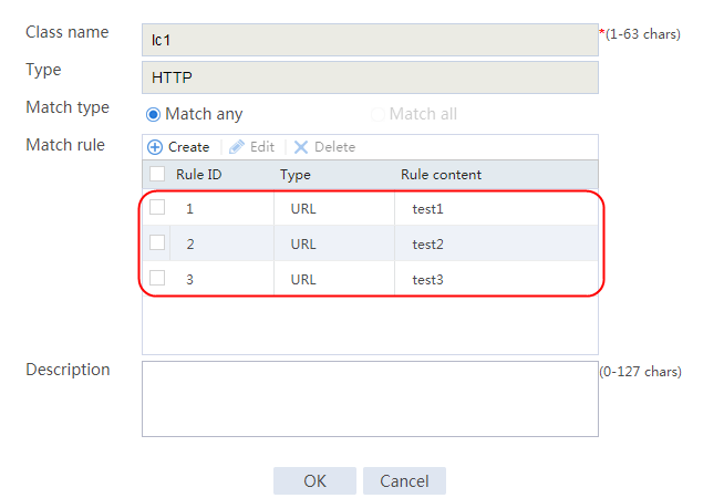
Configuring an LB action
1. Navigate to the LB > Application Load Balancing > Advanced Policies > Actions page.
2. Create an LB action named la1. Specify the type as HTTP, and the primary server farm as sf1.
3. Click Create for Header rewrite. Specify the header name as Location, the header value as .*:8080(.*), and the replacement string as http://61.159.4.100%1. (Value %1 means leave the (.*) content unchanged in the URL.)
Figure 237 Creating an action
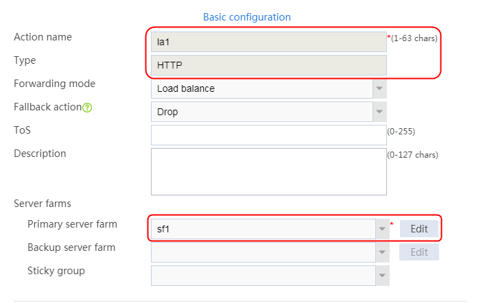
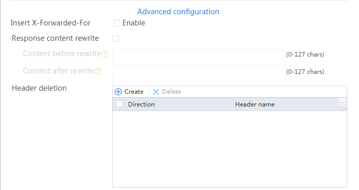
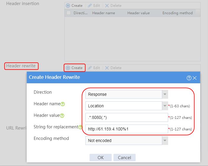

4. Navigate to the LB > Application Load Balancing > Advanced Policies > Actions page.
5. Create an LB action named la2, and specify the type as HTTP, and the primary server farm as sf2.
Figure 238 Creating an action
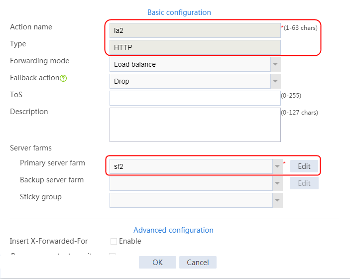
Configuring an LB policy
1. Navigate to the LB > Application Load Balancing > Advanced Policies > LB Policies page.
2. Create an LB policy named lp1, and specify the type as HTTP and the default action as la2. In the Create Rule dialog box, specify class lc1 and action la1.
User requests containing test1, test2, or test3 in the URLs will match LB class lc1 in LB policy lp1. According to LB action la1, the LB device will send the requests to server farm sf1. The Location header content in the returned redirection packet will be replaced with to http://VIP/.
For other requests that do not match LB class lc1, the LB device sends them to server farm sf2 according to LB action la2.
Figure 239 Creating a policy
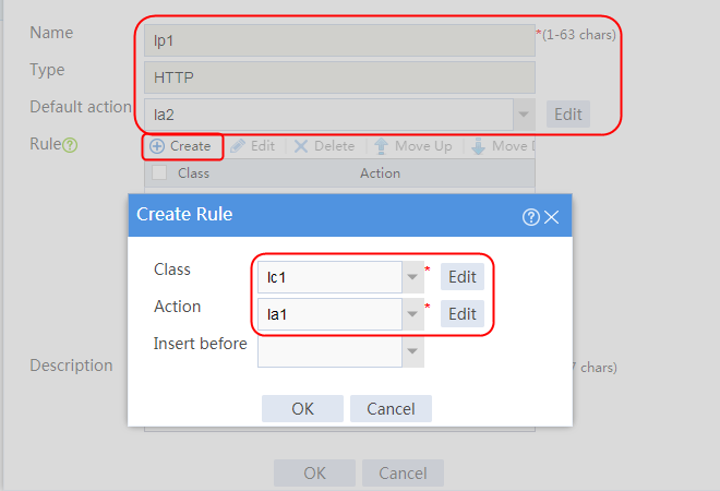
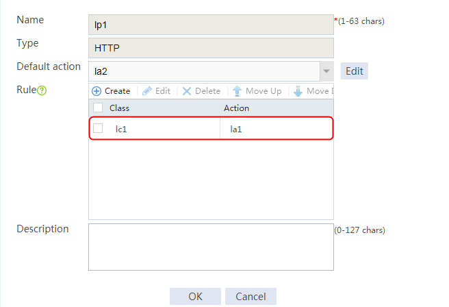
Creating an HTTP LB parameter profile
1. Navigate to the LB > Application Load Balancing > Parameter Profiles page.
2. Create a parameter profile named pp1, specify the type as HTTP, and enable per-packet load balancing.
Figure 240 Creating a parameter profile
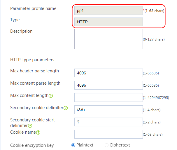
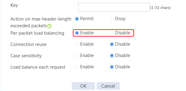
Configuring a virtual server
1. Navigate to the LB > Application Load Balancing > Virtual Servers page.
2. Create a virtual server named vs. Specify the type as HTTP, IP address as 61.159.4.100, and port number as 80. Specify LB policy lp1 and parameter profile pp1, enable the virtual server feature, and then click OK.
Figure 241 Creating a virtual server


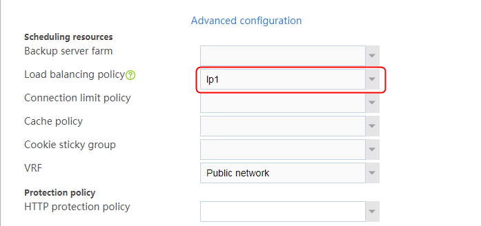
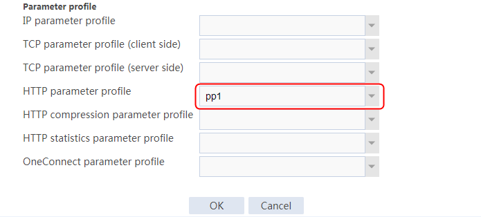
Verifying the configuration
If the client sends a request with URL http://61.159.4.100/test1.html, the following situations will occur:
· The real server responds with a redirection packet with a modified URL of http://192.168.1.1:8080/.
· The LB device replaces the URL returned to the client with http://60.159.4.100/.
· The client uses this URL to access the virtual server successfully.
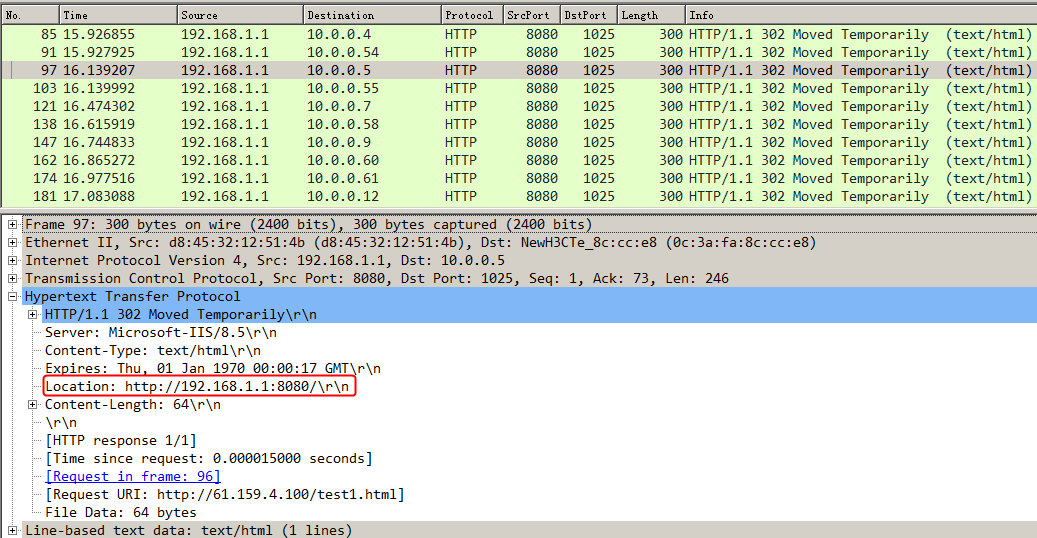
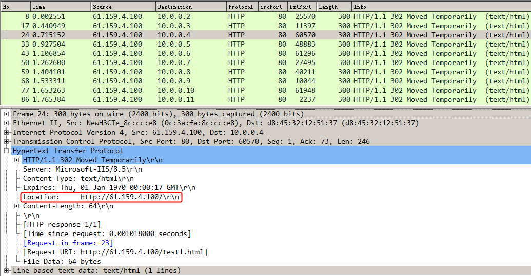
If the client sends a request with URL http://61.159.4.100/test2.html, the following situations will occur:
· The real server responds with a redirection packet with a modified URL of http://61.159.4.100:8080/.
· The LB device replaces the URL returned to the client with http://60.159.4.100/.
· The client uses this URL to access the virtual server successfully.
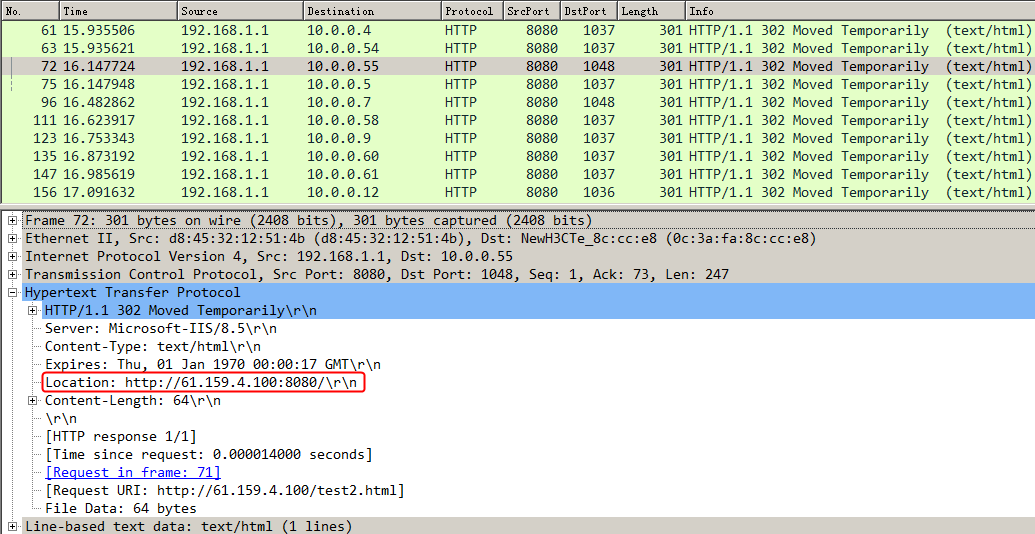
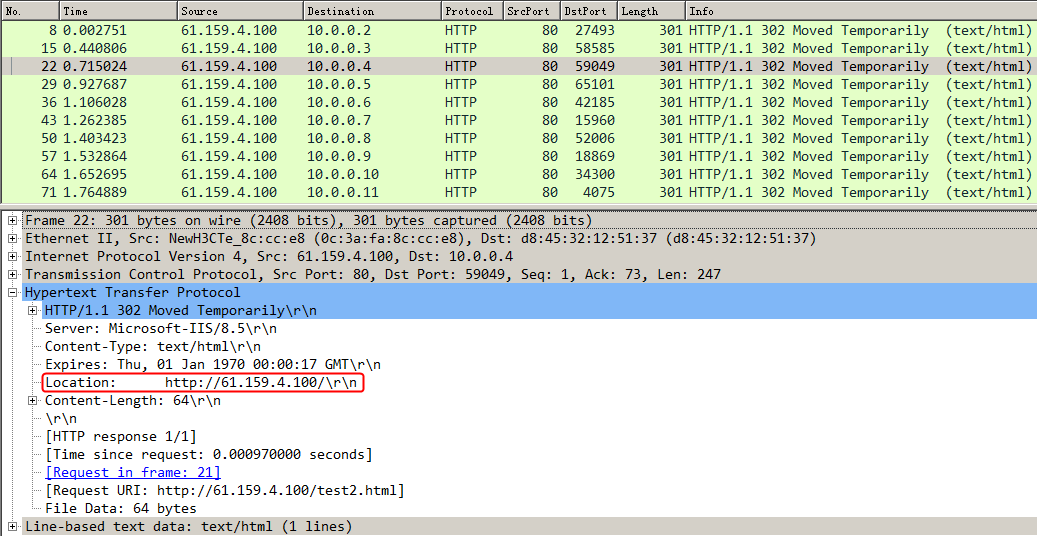
If the client sends a request with URL http://61.159.4.100/test3.html, the following situations will occur:
· The real server responds with a redirection packet with a modified URL of http://www.hello.com:8080/.
· The LB device replaces the URL returned to the client with http://61.159.4.100/.
· The client uses this URL to access the virtual server successfully.


Configuration files
#
nqa template http t1
expect status 200
#
parameter-profile pp1 type http
rebalance per-request
#
server-farm sf1
predictor hash address source
probe t1
success-criteria at-least 1
real-server rs1 port 8080
success-criteria at-least 1
real-server rs2 port 8080
success-criteria at-least 1
#
server-farm sf2
predictor hash address source
probe t1
success-criteria at-least 1
real-server rs11 port 80
success-criteria at-least 1
real-server rs12 port 80
success-criteria at-least 1
#
loadbalance class lc1 type http match-any
match 1 url test1
match 2 url test2
match 3 url test3
#
loadbalance action la1 type http
server-farm sf1
header rewrite response name Location value .*:8080(.*) replace http://61.159.4
.100%1
#
loadbalance action la2 type http
server-farm sf2
#
loadbalance policy lp1 type http
class lc1 action la1
default-class action la2
#
real-server rs1
ip address 192.168.1.1
#
real-server rs11
ip address 192.168.1.11
#
real-server rs12
ip address 192.168.1.12
#
real-server rs2
ip address 192.168.1.2
#
virtual-server vs type http
virtual ip address 61.159.4.100
parameter http pp1
lb-policy lp1
sticky-sync enable global
service enable
#
Example: Configuring HTTP header insertion, rewriting, and deletion
Network configuration
As shown in the Figure 242, a host accesses three servers through the LB device. All these three servers Server A, Server B, and Server C can provide HTTP services. By configuring HTTP-type LB actions on the LB device, you can insert, rewrite, and delete HTTP headers.
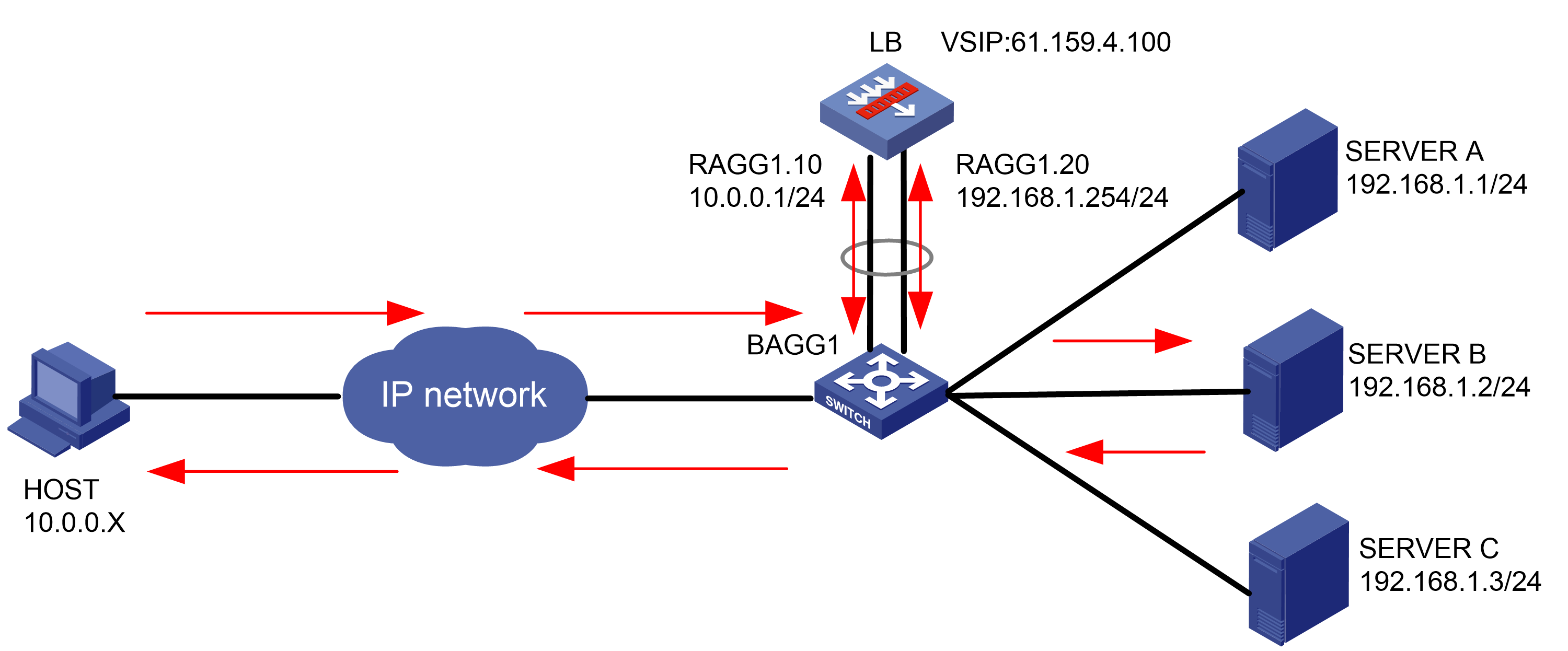
Analysis
To insert, rewrite, and delete HTTP headers, complete the following configuration on the LB device:
· Configure server farm, real server, virtual server, and LB policy settings.
· Enable the LB device to insert, rewrite, and delete HTTP headers.
Software versions used
This configuration example was created and verified on Feature 1160P16 of L1070.
Restrictions and guidelines
When you configure HTTP header insertion, rewriting, and deletion, follow these restrictions and guidelines:
· Make sure a route is available between the host and the LB device.
· Make sure a route is available between the server and the LB device.
· Specify a server farm for the LB actions.
· After configuring the virtual server, you need to enable the virtual server feature.
Procedures
Perform the following configuration on the LB device.
Assigning IP addresses to interfaces
Details not shown.
Creating a health monitoring template
1. Navigate to the LB > Global Configuration > Health Monitoring page.
2. Click Create to create a template named t1, specify the type as HTTP, and set the expected status code to 200.
Figure 243 Creating a health monitoring template
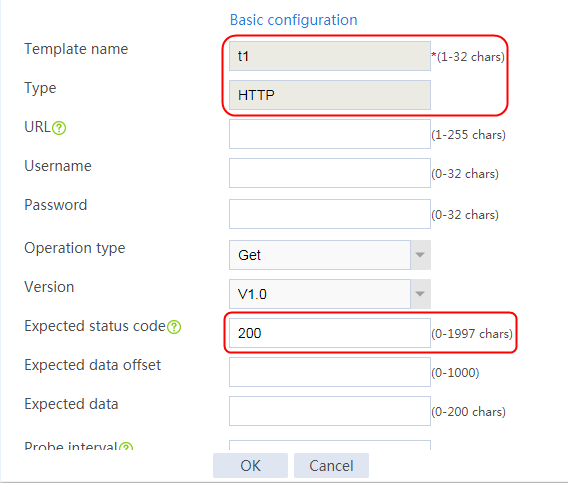
3. Click OK.
Configuring a server farm
1. Navigate to the LB > Application Load Balancing > Server Farms page.
2. Click Create to create a server farm named sf1. Specify the scheduling algorithm as Hash source IP address and probe method as t1.
Figure 244 Creating a server farm

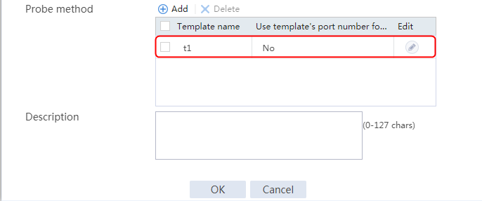
3. Click OK.
Configuring real servers
1. Navigate to the LB > Application Load Balancing > Server Farms page.
2. Edit server farm sf1, and create a real server. Specify the real server name as rs1 and the IP address as 192.168.1.1.
Figure 245 Adding a real server

Figure 246 Creating a real server
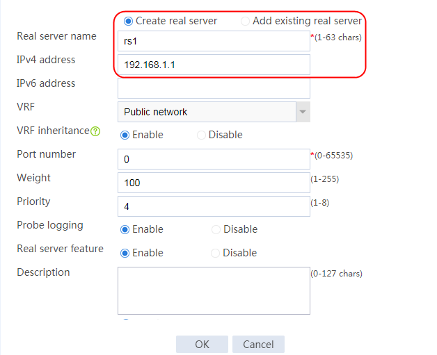
3. Click OK.
4. Create real servers rs2 and rs3 in the same way rs1 is created. Configure their IPv4 addresses as 192.168.1.2 and 192.168.1.3, respectively.
Figure 247 Server farm information
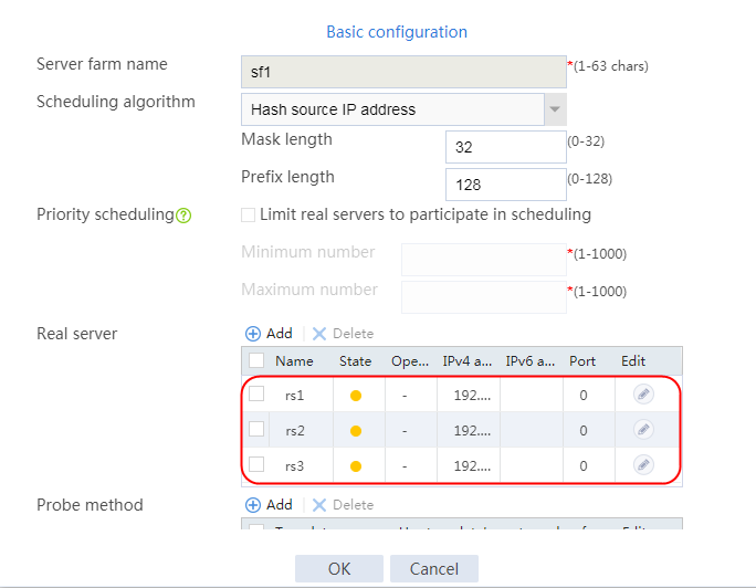
Configuring an LB class
1. Navigate to the LB > Application Load Balancing > Advanced Policies > Classes page.
2. Create an LB class named lc1, and specify the type as HTTP and the match type as Match any. In the Create Match Rule dialog box, set the rule ID to 1, the type to URL, and the URL to test.
Figure 248 Creating a class
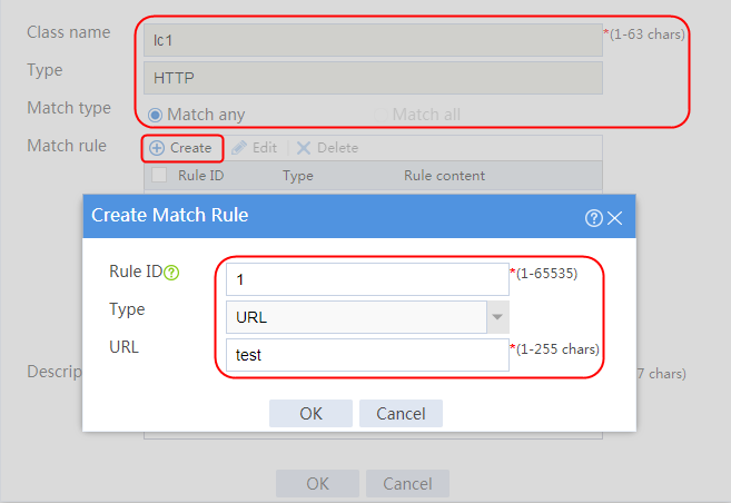
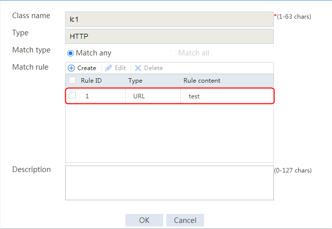
Configuring an LB action
1. Navigate to the LB > Application Load Balancing > Advanced Policies > Actions page.
2. Create an LB action named la1, and specify the type as HTTP and the primary server farm as sf1.
3. In the Create Header Deletion dialog box, specify the direction as Response and the header name as Content-Type.
4. In the Create Header Insertion dialog box, specify the direction as Both and the header name as header-insert-name, and the header value is 21.
5. In the Create Header Rewrite dialog box, specify the direction as request, the header name as host, the header value as 61.159.4.100, and the replacement string as host.com.
Figure 249 Creating an action

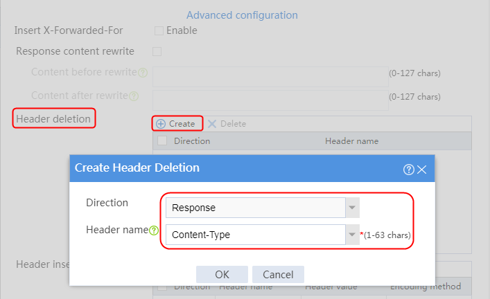
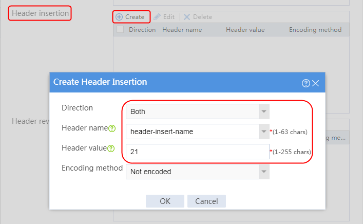
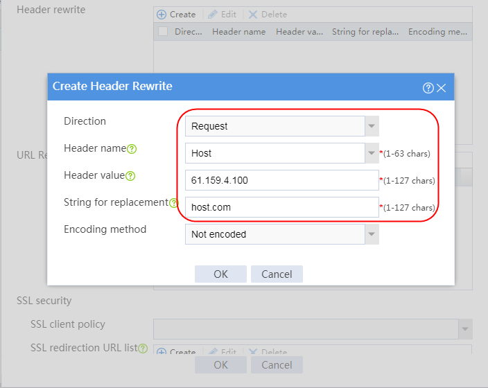
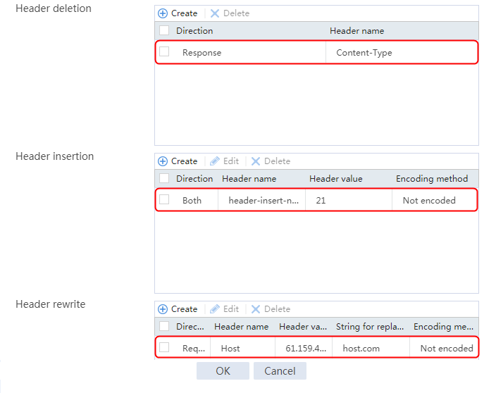
6. Click OK.
Configuring an LB policy
1. Navigate to the LB > Application Load Balancing > Advanced Policies > LB Policies page.
2. Create an LB policy named lp1, and specify the type as HTTP. In the Create Rule dialog box, specify class lc1 and action la1.
User requests containing test in the URL will match LB class lc1 in policy lp1. The LB device will send the requests to server farm sf1 and process the HTTP headers as configured in LB action la1.
Figure 250 Creating an LB policy
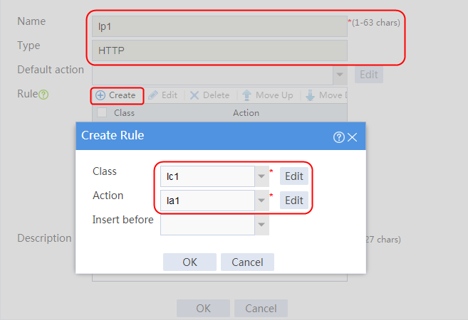
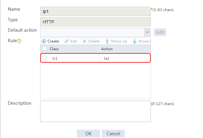
Configuring a virtual server
1. Navigate to the LB > Application Load Balancing > Virtual Servers page.
2. Create a virtual server named vs. Specify the type as HTTP, IP address as 61.159.4.100, default server farm as sf1, and port number as 80. Specify LB policy lp1, enable the virtual server feature, and click OK.
Figure 251 Creating a virtual server
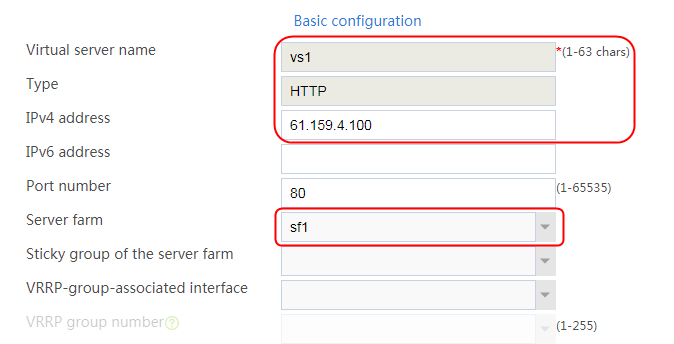
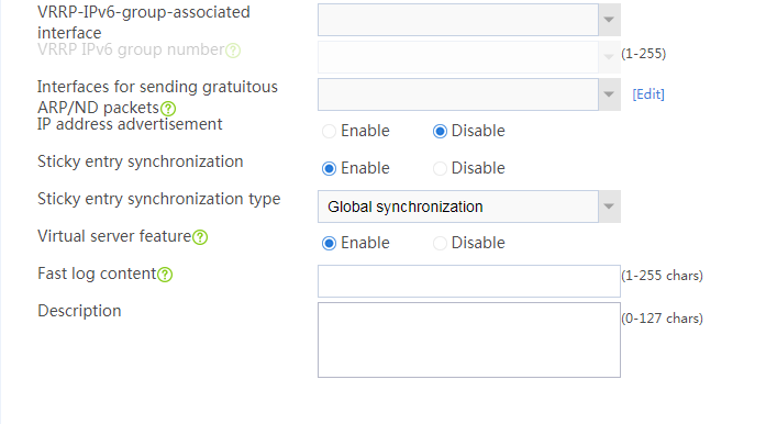
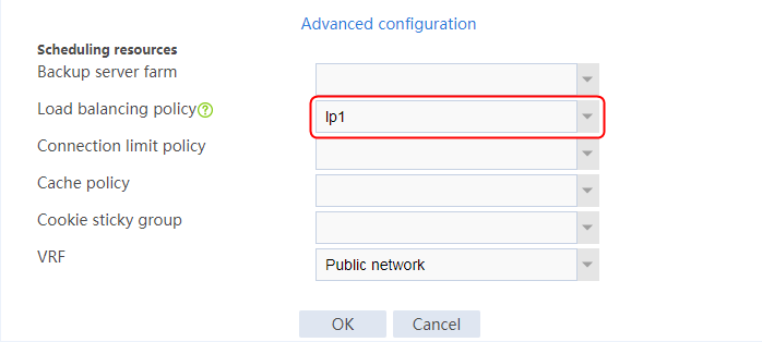
Verifying the configuration
View the packets captured on the client and server ends.
Header insertion
View request packets on the client.
Figure 252 Request packets for header insertion on the client
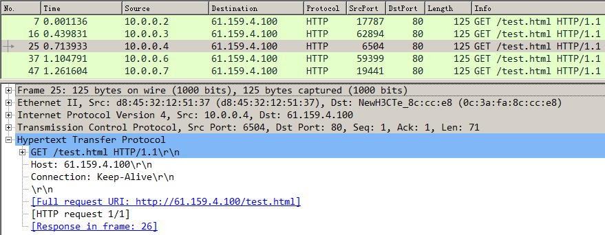
View request packets on the server.
Figure 253 Request packets for header insertion on the server
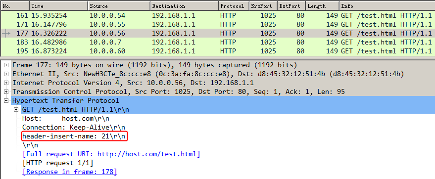
View response packets on the server.
Figure 254 Response packets for header insertion on the server
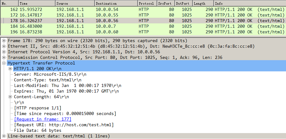
View response packets on the client.
Figure 255 Response packets for header insertion on the client
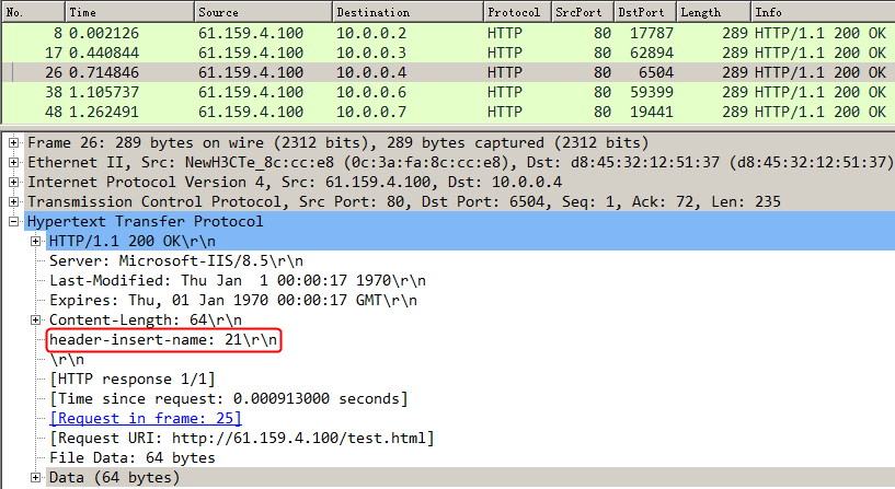
Header rewrite
View request packets on the client.
Figure 256 Request packets for header rewrite on the client
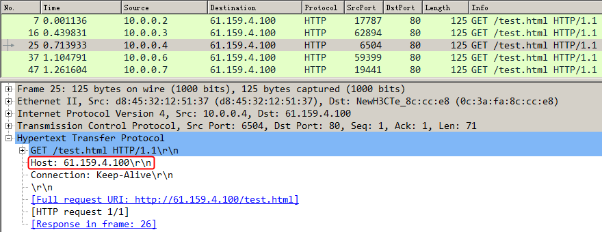
View request packets on the server.
Figure 257 Request packets for header rewrite on the server
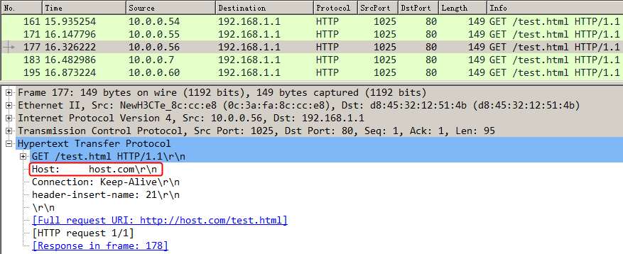
Header deletion
Compared with the packet captured on the server, the header content content-type is deleted from the HTTP response packet captured on the client.
View response packets on the server.
Figure 258 Response packets for header deletion on the server
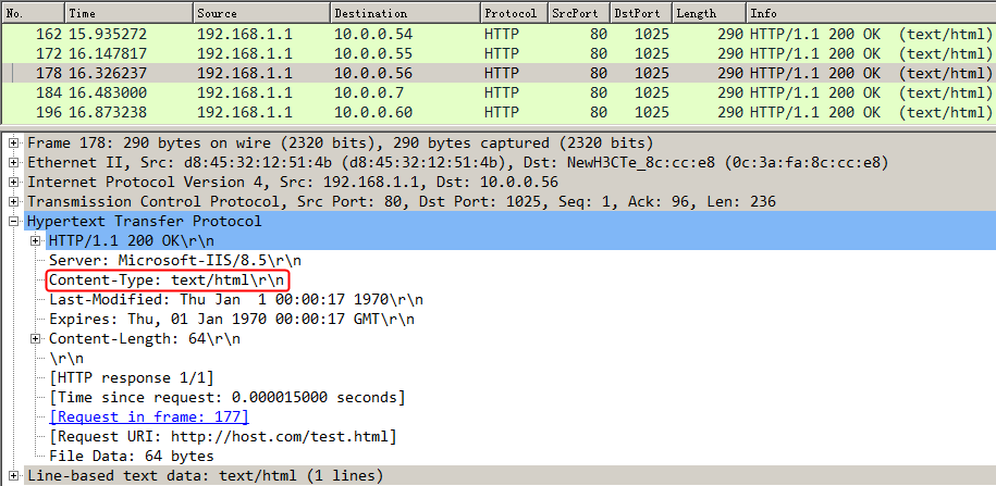
View response packets on the client.
Figure 259 Response packets for header deletion on the client
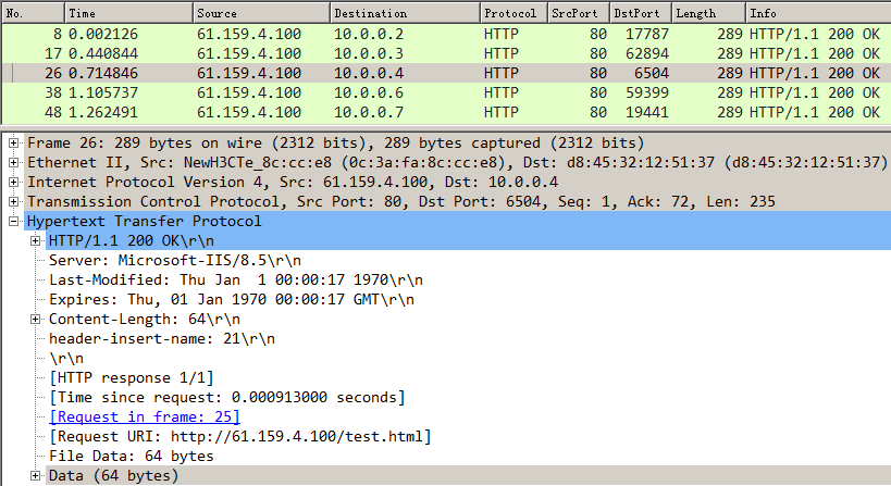
Configuration files
#
nqa template http t1
expect status 200
#
server-farm sf1
predictor hash address source
probe t1
success-criteria at-least 1
real-server rs1 port 0
success-criteria at-least 1
real-server rs2 port 0
success-criteria at-least 1
real-server rs3 port 0
success-criteria at-least 1
#
loadbalance class lc1 type http match-any
match 1 url test
#
loadbalance action la1 type http
server-farm sf1
header delete response name Content-Type
header insert both name header-insert-name value 21
header rewrite request name Host value 61.159.4.100 replace host.com
#
loadbalance policy lp1 type http
class lc1 action la1
#
real-server rs1
ip address 192.168.1.1
#
real-server rs2
ip address 192.168.1.2
#
real-server rs3
ip address 192.168.1.3
#
virtual-server vs type http
virtual ip address 61.159.4.100
lb-policy lp1
default server-farm sf1
sticky-sync enable global
service enable
#
Example: Configuring HTTP cookie insert, rewrite, and get sticky methods
Network configuration
The host accesses three servers through the LB device. The servers can provide HTTP services. You can configure the cookie insert, cookie rewrite, and cookie get sticky methods to perform operations on HTTP response packets sent by the server.
· The cookie insert sticky method inserts the Set-Cookie field to the HTTP response packets sent by the server.
· The cookie rewrite sticky method rewrites the Set-Cookie field in the HTTP response packets sent by the server.
· The cookie get sticky method gets the Set-Cookie field in the HTTP response packets sent by the server.
Figure 260 Network diagram

Analysis
To insert, rewrite, and get HTTP cookies, complete the following configuration on the LB device:
· Configure server farm, real server, virtual server, and sticky group settings.
· The LB device can insert, rewrite, and get HTTP cookies, and can distribute services to a specific server based on sticky entries.
Software versions used
This configuration example was created and verified on Feature 1160P16 of L1070.
Restrictions and guidelines
When you configure the HTTP cookie insert, rewrite, and get sticky methods, follow these restrictions and guidelines:
· Make sure a route is available between the host and the LB device.
· Make sure a route is available between the server and the LB device.
· Specify sticky groups for the virtual server.
· After configuring the virtual server, you need to enable the virtual server feature.
Procedures
Perform the following configuration on the LB device.
Assigning IP addresses to interfaces
Details not shown.
Creating a health monitoring template
1. Navigate to the LB > Global Configuration > Health Monitoring page.
2. Click Create to create a template named t1, specify the type as HTTP, and set the expected status code to 200.
Figure 261 Creating a health monitoring template

3. Click OK.
Creating a server farm
1. Navigate to the LB > Application Load Balancing > Server Farms page.
2. Click Create to create a server farm named sf1. Specify the scheduling algorithm as Hash source IP address and probe method as t1.
Figure 262 Creating a server farm

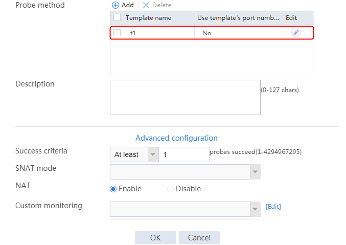
3. Click OK.
Configuring real servers
1. Navigate to the LB > Application Load Balancing > Server Farms page.
2. Edit server farm sf1, and click Add to create a real server. Specify the real server name as rs1 and the IP address as 192.168.1.1.
Figure 263 Adding a real server

Figure 264 Creating a real server

3. Click OK.
4. Create real servers rs2 and rs3 in the same way rs1 is created. Configure their IPv4 addresses as 192.168.1.2 and 192.168.1, respectively.
Figure 265 Server farm information

Creating a sticky group
1. Navigate to the LB > Global Configuration > Sticky Groups page.
2. Click Create to create a sticky group named cookie_insert, set the type to HTTP-Cookie, the cookie stickiness to Cookie insertion, and the cookie name to X-LB.
Figure 266 Creating a sticky group cookie_insert
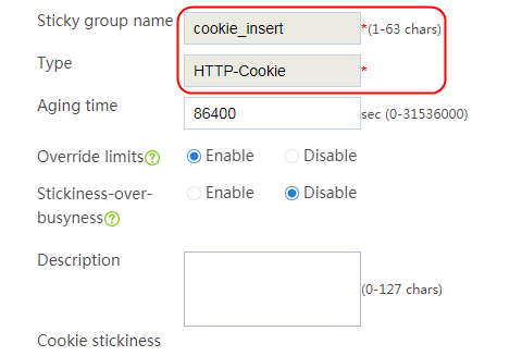
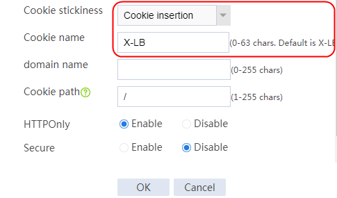
3. Click OK.
4. Navigate to the LB > Global Configuration > Sticky Groups page.
5. Click Create to create a sticky group named cookie_rewrite, set the type to HTTP-Cookie, the cookie stickiness to Cookie rewrite, and the cookie name to cookie_rewrite.
Figure 267 Creating a sticky group cookie_rewrite
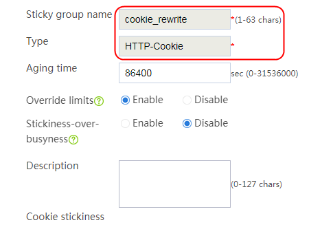

6. Click OK.
7. Navigate to the LB > Global Configuration > Sticky Groups page.
8. Click Create to create a sticky group named cookie_get, and set the type to HTTP-Cookie, the cookie stickiness to Cookie get, and the cookie name to cookie_get.
Figure 268 Creating a sticky group cookie_get
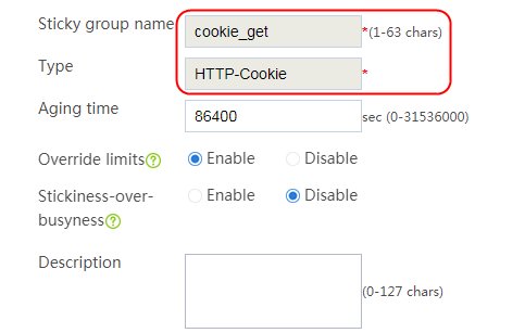
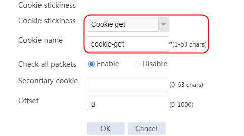
9. Click OK.
Configuring an LB class
1. Navigate to the LB > Application Load Balancing > Advanced Policies > Class page.
2. Click Create to create a class named lc1, and specify the type as HTTP. In the Create Match Rule dialog box, set the rule ID to 1, the type to URL, and the URL to test1.
Figure 269 Creating class lc1
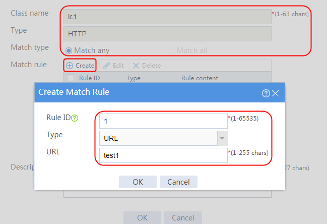
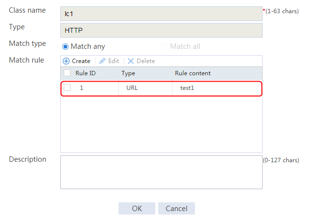
3. Click OK.
4. Navigate to the LB > Application Load Balancing > Advanced Policies > Class page.
5. Click Create to create a class named lc2, and specify the type as HTTP. In the Create Match Rule dialog box, set the rule ID to 1, the type to URL, and the URL to test2.
Figure 270 Creating a class lc2
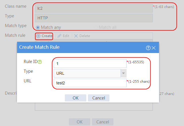
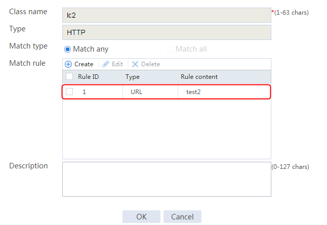
6. Click OK.
Configuring LB actions
1. Navigate to the LB > Application Load Balancing > Advanced Policies > Action page.
2. Click Create to create an action named la1 Specify the type as HTTP, the primary server farm as sf1, and the sticky group as cookie_insert.
Figure 271 Creating action la1
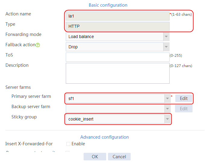
3. Click OK.
4. Navigate to the LB > Application Load Balancing > Advanced Policies > Action page.
5. Click Create to create an action named la2. Specify the type as HTTP, the primary server farm as sf1, and the sticky group as cookie_rewrite.
Figure 272 Creating action la2
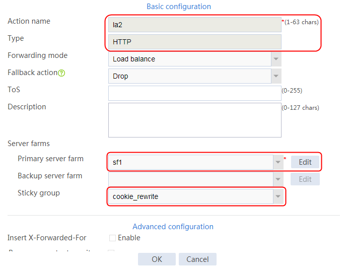
6. Click OK.
7. Navigate to the LB > Application Load Balancing > Advanced Policies > Action page.
8. Click Create to create an action named la3. Specify the type as HTTP, the primary server farm as sf1, and the sticky group as cookie_get.
Figure 273 Creating action la2
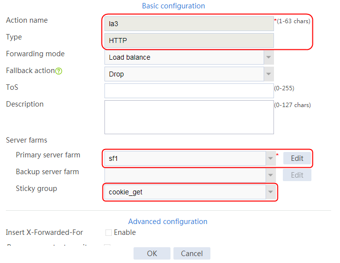
9. Click OK.
Configuring an LB policy
1. Navigate to the LB > Application Load Balancing > Advanced Policies > LB Policies page.
2. Create an LB policy named lp1, specify the type as HTTP, and specify the default action as la3.
3. Click Create. In the Create Rule dialog box, specify class lc1 and action la1.
4. Click Create. In the Create Rule dialog box, specify class lc2 and action la2.
User requests containing test1 in the URL will match LB class lc1 in LB policy lp1. The LB device will send the requests to server farm sf1, and process the HTTP header based on LB action la1.
Figure 274 Creating an LB policy
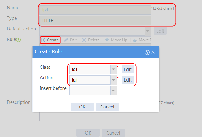
5. Click OK.
Figure 275 LB policy information
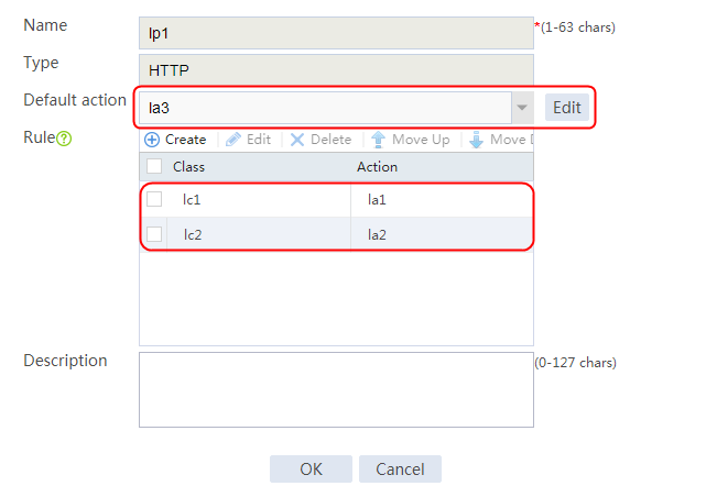
Configuring a virtual server
1. Navigate to the LB > Application Load Balancing > Virtual Servers page.
2. Create a virtual server named vs1. Specify the type as HTTP, IPv4 address as 61.159.4.100, default server farm as sf1, and port number as 80. Enable the virtual server feature, and then click OK.
Figure 276 Creating virtual server vs1
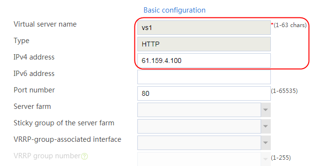
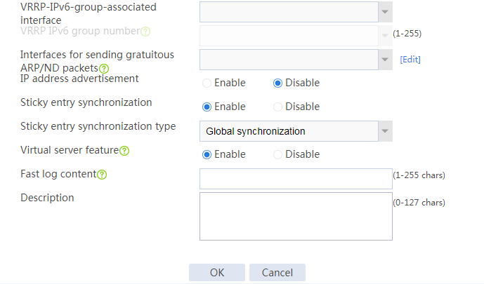
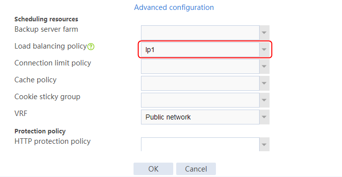
3. Click OK.
Verifying the configuration
Viewing sticky entries
<Sysname>display sticky virtual-server
Slot 1:
Virtual server name: vs1
Server-farm name: sf1
Class: lc1
Sticky group name: cookie_insert
Sticky type: HTTP cookie
Sticky method: Cookie Insert
Sticky Key: 2.8.b092d037.0
Real server addr: 192.168.1.1:0
Cookie name: X-LB
Cookie domain:
Cookie path: /
HttpOnly: Disabled
Secure: Disabled
Timeout: 86400
------------------------------------------
Virtual server name: vs1
Server-farm name: sf1
Class: lc1
Sticky group name: cookie_insert
Sticky type: HTTP cookie
Sticky method: Cookie Insert
Sticky Key: 2.e.c55bd498.0
Real server addr: 192.168.1.2:0
Cookie name: X-LB
Cookie domain:
Cookie path: /
HttpOnly: Disabled
Secure: Disabled
Timeout: 86400
------------------------------------------
Virtual server name: vs1
Server-farm name: sf1
Class: lc1
Sticky group name: cookie_insert
Sticky type: HTTP cookie
Sticky method: Cookie Insert
Sticky Key: 2.11.7707dba7.0
Real server addr: 192.168.1.3:0
Cookie name: X-LB
Cookie domain:
Cookie path: /
HttpOnly: Disabled
Secure: Disabled
Timeout: 86400
------------------------------------------
Virtual server name: vs1
Server-farm name: sf1
Class: lc2
Sticky group name: cookie_rewrite
Sticky type: HTTP cookie
Sticky method: Cookie Rewrite
Sticky Key: 2.7.19ba92e3.0
Real server addr: 192.168.1.1:0
Cookie name: X-LB
HttpOnly: Disabled
Secure: Disabled
Timeout: 86400
------------------------------------------
Virtual server name: vs1
Server-farm name: sf1
Class: lc2
Sticky group name: cookie_rewrite
Sticky type: HTTP cookie
Sticky method: Cookie Rewrite
Sticky Key: 2.d.8013df67.0
Real server addr: 192.168.1.2:0
Cookie name: X-LB
HttpOnly: Disabled
Secure: Disabled
Timeout: 86400
------------------------------------------
Virtual server name: vs1
Server-farm name: sf1
Class: lc2
Sticky group name: cookie_rewrite
Sticky type: HTTP cookie
Sticky method: Cookie Rewrite
Sticky Key: 2.10.8af0cfe3.0
Real server addr: 192.168.1.3:0
Cookie name: X-LB
HttpOnly: Disabled
Secure: Disabled
Timeout: 86400
You can clear real server and virtual server statistics before sending traffic for verification.
1. Navigate to the Monitor > Application Load Balancing > Virtual Servers > Real-time Statistics page.
2. Click Clear.
Figure 277 Clearing virtual server statistics
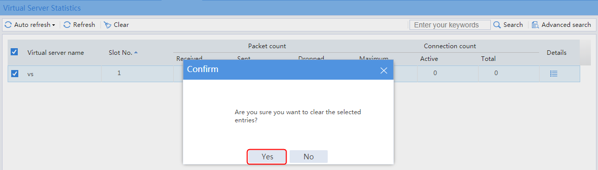
3. Navigate to the Monitor > Application Load Balancing > Real Servers > Real-time Statistics page.
4. Click Clear.
Figure 278 Clearing real server statistics
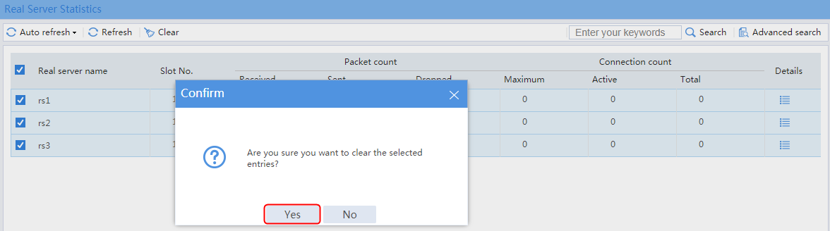
Verifying cookie insertion
1. Initiate a request with URL http://61.149.4.100/test1, and capture packets on the host. The LB device inserts Set-Cookie: X-LB=2.8.b092d037.0 to the HTTP response packet.
2. On the server, capture HTTP response packets.
Figure 279 HTTP response packets captured on the server
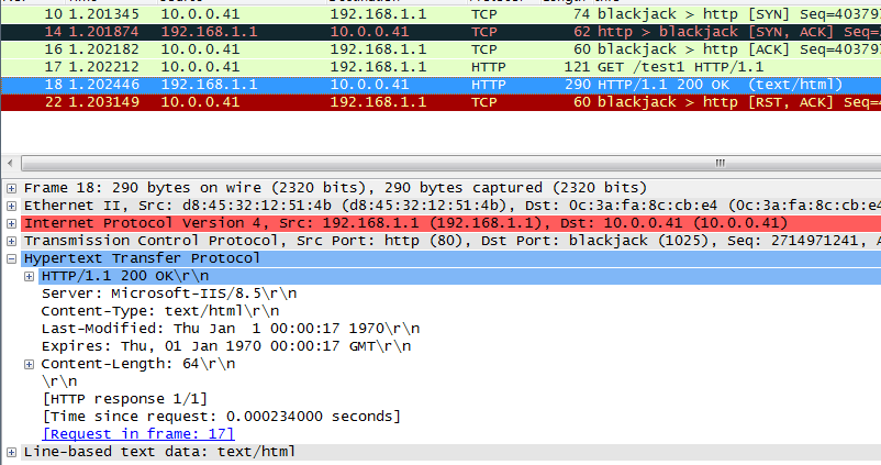
3. On the host, capture HTTP response packets.
Figure 280 HTTP response packets captured on the host
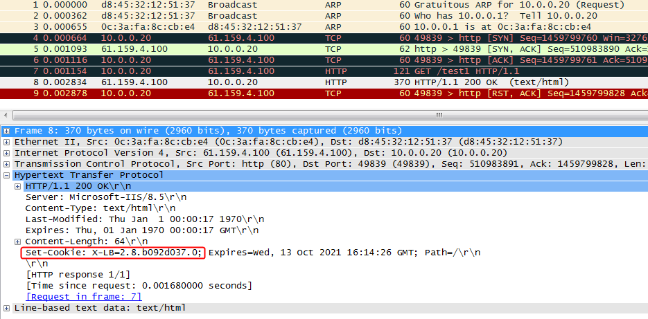
4. When the traffic is injected for the first time, the LB device returns a cookie value (Set-Cookie: X-LB=2.8.b092d037.0) associated with rs1. View load balancing information on the real servers. Only rs1 has statistics.
5. Navigate to the Monitor > Application Load Balancing > Real Servers > Real-time Statistics page. View the traffic statistics. (Details not shown.)
6. The second request carries the inserted Cookie value (2.8.b092d037.0), inject traffic to verify that stickiness takes effect, and all requests are assigned to the same real server rs1.
7. Navigate to the Monitor > Application Load Balancing > Real Servers > Real-time Statistics page. View the traffic statistics. (Details not shown.)
Verifying cookie rewrite
1. Initiate a request with URL http://61.149.4.100/test2, and capture packets on the host. The LB device rewrites the cookie from 2.8.b092d037.0 to 2.7.19ba92e3.0 in the HTTP response packet.
2. On the server, capture HTTP response packets.
Figure 281 HTTP response packets captured on the server
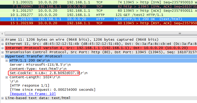
3. On the host, capture HTTP response packets.
Figure 282 HTTP response packets captured on the host
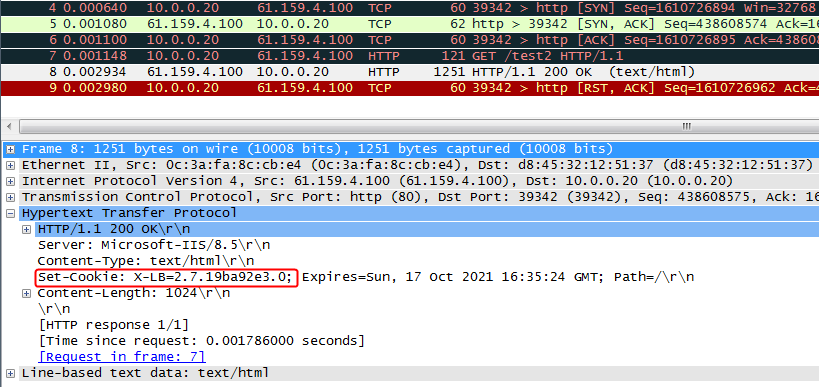
4. When the traffic is injected for the first time, the cookie value (Set-Cookie: X-LB=2.8.b092d037.0) carried by the server is rewritten by the LB device to 2.7.19ba92e3.0 associated with rs1. View load balancing information on the real servers. Only rs1 has statistics.
5. Navigate to the Monitor > Application Load Balancing > Real Servers > Real-time Statistics page. View the traffic statistics. (Details not shown.)
6. The second request carries the rewritten Cookie value (2.7.19ba92e3.0), inject traffic to verify that stickiness takes effect, and all requests are assigned to the same real server rs1.
7. Navigate to the Monitor > Application Load Balancing > Real Servers > Real-time Statistics page. View the traffic statistics. (Details not shown.)
Verifying cookie get
1. Initiate a request with URL http://61.149.4.100/test3, and capture packets on the host and server ends to verify that the packets carry the cookie field (cookie-get=6.6.b092d037.0).
You can see that no change occurs in the cookie. (Details not shown.)
When the traffic is injected for the first time, the request is allocated to real server rs1.
Figure 283 HTTP response packet captured on the server
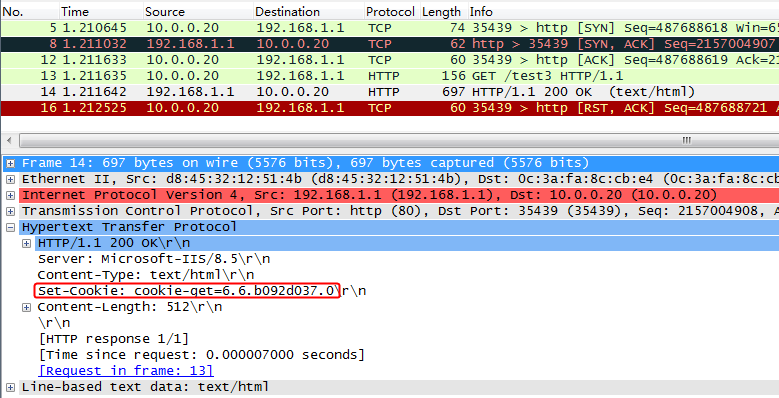
Figure 284 HTTP response packet captured on the host
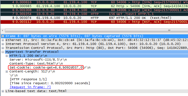
2. Carry the cookie value in the request. Verify that stickiness takes effect, and all requests are assigned to the same real server.
When the traffic is injected for the first time, the request is allocated to real server rs1. Only rs1 has statistics.
3. Navigate to the Monitor > Application Load Balancing > Real Servers > Real-time Statistics page. View the traffic statistics. (Details not shown.)
4. The second request carries the inserted cookie value (2.8.b092d037.0), inject traffic to verify that stickiness takes effect, and all requests are assigned to the same real server rs1.
5. Navigate to the Monitor > Application Load Balancing > Real Servers > Real-time Statistics page. View the traffic statistics. (Details not shown.)
Configuration files
#
nqa template http t1
expect status 200
#
sticky-group cookie_get type http-cookie
cookie get name cookie-get
check all-packet
#
sticky-group cookie_insert type http-cookie
cookie insert
check all-packet
#
sticky-group cookie_rewrite type http-cookie
cookie rewrite
check all-packet
#
server-farm sf1
predictor hash address source
success-criteria at-least 1
real-server rs1 port 0
success-criteria at-least 1
real-server rs2 port 0
success-criteria at-least 1
real-server rs3 port 0
success-criteria at-least 1
#
loadbalance class lc1 type http match-any
match 1 url test1
#
loadbalance class lc2 type http match-any
match 1 url test2
#
loadbalance action la1 type http
server-farm sf1 sticky cookie_insert
#
loadbalance action la2 type http
server-farm sf1 sticky cookie_rewrite
#
loadbalance action la3 type http
server-farm sf1 sticky cookie_get
#
loadbalance policy lp1 type http
class lc1 action la1
class lc2 action la2
default-class action la3
#
real-server rs1
ip address 192.168.1.1
#
real-server rs2
ip address 192.168.1.2
#
real-server rs3
ip address 192.168.1.3
#
virtual-server vs1 type http
virtual ip address 61.159.4.100
lb-policy lp1
sticky-sync enable global
service enable
#
Example: Configuring SSL offloading
Network configuration
SSL offloading enables the LB device to provide SSL encryption and decryption services for the Web server on the internal network, and provide secure access (SSL encryption) to the Web server externally. The internal Web server only needs to process services without performing SSL encryption and decryption, improving the processing capacity of the server.
The LB device encrypts and decrypts the HTTPS access request from the host to three servers Server A, Server B, and Server C in the public network that can all provide HTTP services. The host traffic will be load-shared among the three servers.
Figure 285 Network diagram

Analysis
To implement SSL offloading, complete the following configuration on the LB device:
· Import the CA and local certificates to the LB device, and create an SSL server policy on the LB device.
· Configure server farm, real server, and virtual server settings.
· The client can access the HTTP server successfully through HTTPS.
Software versions used
This configuration example was created and verified on Feature 1160P16 of L1070.
Restrictions and guidelines
When you configure the SSL offloading function, follow these restrictions and guidelines:
· Make sure a route is available from the host to the LB device.
· You must first apply for the correct certificate, and then upload the certificate to the LB device through FTP or TFTP.
· Specify the real server addresses on the LB device as the actual server addresses.
· After configuring the virtual server, you need to enable the virtual server feature.
· Configure the port number of the virtual server as 443, and the port number of the real server as 80.
· When the SSL server policy is modified, you must disable and enable the virtual server again to make the configuration effective.
· After creating an SSL server policy, use relevant commands to manually enable the SSL server to send the complete certificate chain during SSL negotiation.
Procedures
Perform the following configuration on the LB device.
Assigning IP addresses to interfaces
Details not shown.
Creating a PKI domain and disabling CRL checking
1. Navigate to the Objects > KPI > Certificates page.
2. Click Create to create a PKI domain named ca, and disable CRL checking.
Figure 286 Creating a PKI domain
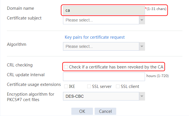
3. Click OK.
Importing the CA certificate and local certificate into the PKI domain
1. Select the created PKI domain ca, and click Import Certificate.
Figure 287 Importing a certificate

2. Specify the certificate type as CA certificate, click Select file, and select the CA certificate file.
Figure 288 Importing a CA certificate

3. Click OK and then click Yes to confirm the fingerprint information.
Figure 289 Certificate fingerprint information

4. Specify the certificate type as Local certificate, click Select file, select the local certificate file, and enter the password for certificate.
Figure 290 Importing a local certificate
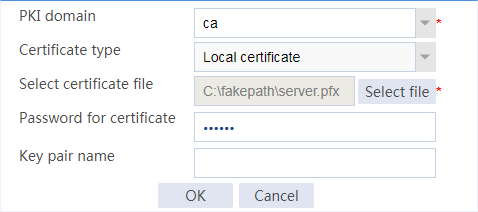
5. Click OK.
Creating an SSL server policy
1. Navigate to the Objects > SSL > Server Policies page.
2. Click Create to create an SSL server policy named ssl, and specify the PKI domain as ca.
Figure 291 Creating an SSL server policy
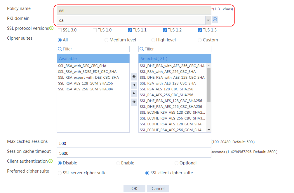
3. Click OK.
4. Execute the following commands to manually enable the SSL server to send a complete certificate chain during SSL negotiation (the configuration is not supported on the Web interface):
[Sysname]ssl server-policy ssl
[Sysname-ssl-server-policy-ssl]certificate-chain-sending enable
Creating a health monitoring template
1. Navigate to the LB > Global Configuration > Health Monitoring page.
2. Click Create to create a template named t1, specify the type as HTTP, and set the expected status code to 200.
Figure 292 Creating a health monitoring template

3. Click OK.
Configuring a server farm
1. Navigate to the LB > Application Load Balancing > Server Farms page.
2. Click Create to create a server farm named sf1. Specify the scheduling algorithm as Hash source IP address and probe method as t1.
Figure 293 Creating a server farm


3. Click OK.
Configuring the real server
1. Navigate to the LB > Application Load Balancing > Server Farms page.
2. Edit server farm sf1, and click Add to create a real server. Specify the real server name as rs1, IP address as 192.168.1.1, and port number as 80.
Figure 294 Adding a real server

Figure 295 Creating a real server
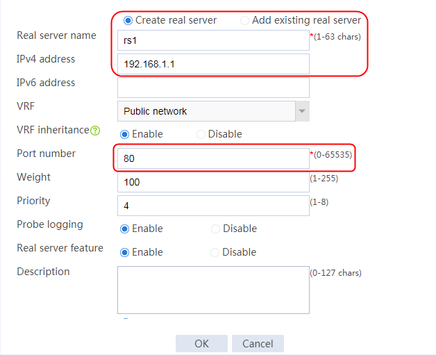
3. Click OK.
4. Create real server rs2 in the same way rs1 is created:
a. Navigate to the LB > Application Load Balancing > Server Farms page.
b. Edit server farm sf2 to add a real server.
c. Create real server rs2 as shown in the figure above. Configure its IPv4 address as 192.168.1.2 and port number as 80.
5. Create real server rs3 in the same way rs1 is created:
a. Navigate to the LB > Application Load Balancing > Server Farms page.
b. Edit server farm sf2 to add a real server.
c. Create real server rs3 as shown in the figure above. Configure its IPv4 address as 192.168.1.3 and port number as 80.
Figure 296 Server farm information

Configuring a virtual server
1. Navigate to the LB > Application Load Balancing > Virtual Servers page.
2. Click Create to create a virtual server named vs. Specify the type as HTTPS, virtual IP address as 61.159.4.100, default server farm as sf1, and port number as 443. Specify SSL policy ssl, and enable the virtual server feature.
Figure 297 Creating a virtual server
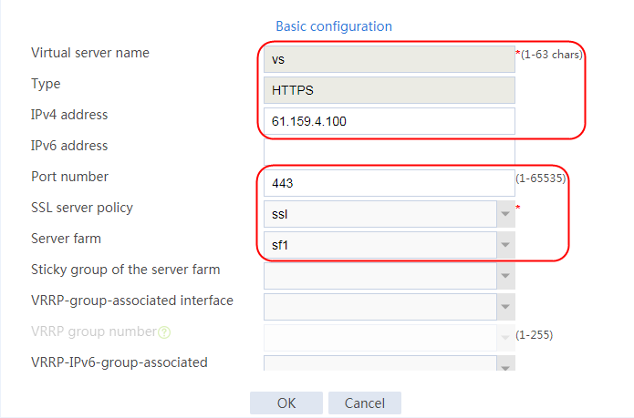
3. Click OK.
Verifying the configuration
The host accesses the HTTP server through https://61.159.4.100 successfully. The packets exchanged between the client and the device are in encrypted form. View captured packet information on the client.
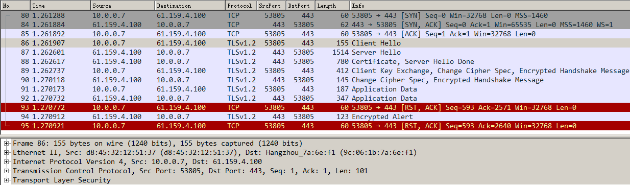
The packets exchanged between the device and the server are in plaintext form. View captured packet information on the server.

Configuration files
#
nqa template http t1
expect status 200
#
pki domain ca
public-key rsa general name ca length 2048
undo crl check enable
#
ssl server-policy ssl
pki-domain ca
ciphersuite dhe_rsa_aes_256_cbc_sha rsa_aes_256_cbc_sha dhe_rsa_aes_128_cbc_sha
rsa_aes_128_cbc_sha rsa_aes_128_cbc_sha256 rsa_aes_256_cbc_sha256 dhe_rsa_aes_1
28_cbc_sha256 dhe_rsa_aes_256_cbc_sha256 ecdhe_rsa_aes_128_cbc_sha256 ecdhe_rsa_
aes_256_cbc_sha384 ecdhe_rsa_aes_128_gcm_sha256
ciphersuite ecdhe_rsa_aes_256_gcm_sha384 ecdhe_ecdsa_aes_128_cbc_sha256 ecdhe_e
cdsa_aes_256_cbc_sha384 ecdhe_ecdsa_aes_128_gcm_sha256 ecdhe_ecdsa_aes_256_gcm_s
ha384 tls_aes_128_gcm_sha256 tls_aes_256_gcm_sha384 tls_chacha20_poly1305_sha256
tls_aes_128_ccm_sha256 tls_aes_128_ccm_8_sha256
certificate-chain-sending enable
version ssl3.0 disable
version tls1.0 disable
undo version gm-tls1.1 disable
#
server-farm sf1
predictor hash address source
probe t1
success-criteria at-least 1
real-server rs1 port 80
success-criteria at-least 1
real-server rs2 port 80
success-criteria at-least 1
real-server rs3 port 80
success-criteria at-least 1
#
real-server rs1
ip address 192.168.1.1
#
real-server rs2
ip address 192.168.1.2
#
real-server rs3
ip address 192.168.1.3
#
virtual-server vs type http
port 443
virtual ip address 61.159.4.100
default server-farm sf1
ssl-server-policy ssl
sticky-sync enable global
service enable
#
Example: Configuring SSL client certificate transparent transmission
Network configuration
The LB device encrypts and decrypts the HTTPS access request from the host to three servers Server A, Server B, and Server C that can all provide HTTP services. The host traffic will be load-shared among the three servers. Enable SSL client verification for the LB device to insert common certificate fields in client requests, so that the server can determine whether the received access comes from a trusted client.
Figure 298 Network diagram

Analysis
To implement the SSL client certificate transparent transmission function, complete the following configuration on the LB device:
· Import the CA certificate and local certificate to the LB device, and create an SSL server policy on the LB device.
· Configure server farm, real server, and virtual server settings.
· The client can access the HTTP server successfully through HTTPS.
· Configure the LB action and insert the common fields of the certificate.
· The common certificate field content to be inserted is a string of 1 to 255 characters. You can also specify the following values:
¡ %{x509v}—Certificate version.
¡ %{x509snum}—Certificate serial number.
¡ %{x509sigalgo}—Certificate signature algorithm.
¡ %{x509issuer}—Certificate issuer.
Software versions used
This configuration example was created and verified on Feature 1160P16 of L1070.
Restrictions and guidelines
When you configure SSL client certificate transparent transmission, follow these restrictions and guidelines:
· You must first apply for the correct certificate, and then upload the certificate to the LB device through FTP or TFTP.
· Enable client verification for the SSL server policy, and import the correct CA certificate and local certificate to the client.
· Configure the port number of the virtual server as 443, and the port number of the real server as 80.
· When the SSL server policy is modified, you must disable and enable the virtual server again to make the configuration effective.
· After creating an SSL server policy, use relevant commands to manually enable the SSL server to send the complete certificate chain during SSL negotiation.
Procedures
Perform the following configuration on the LB device.
Assigning IP addresses to interfaces
Details not shown.
Creating a PKI domain and disabling CRL checking
1. Navigate to the Objects > KPI > Certificates page.
2. Click Create to create a PKI domain named ca, and disable CRL checking.
Figure 299 Creating a PKI domain

3. Click OK.
Importing the CA certificate and local certificate
1. Select the created PKI domain ca, and click Import Certificate.
Figure 300 Importing a certificate

2. Specify the certificate type as CA certificate, click Select file, and select the CA certificate file.
Figure 301 Importing a CA certificate

3. Click OK and then click Yes to confirm the fingerprint information.
Figure 302 Certificate fingerprint information

4. Specify the certificate type as Local certificate, click Select file, select the local certificate file, and enter the password for certificate.
Figure 303 Importing a local certificate

5. Click OK.
Creating an SSL server policy
1. Navigate to the Objects > SSL > Server Policies page.
2. Click Create to create an SSL server policy named ssl, specify the PKI domain as ca, and enable client authentication.
Figure 304 Creating an SSL server policy
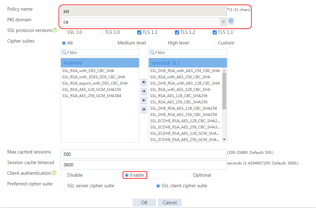
3. Click OK.
4. Execute the following commands to manually enable the SSL server to send a complete certificate chain during SSL negotiation (the configuration is not supported on the Web interface):
[Sysname] ssl server-policy ssl
[Sysname-ssl-server-policy-ssl] certificate-chain-sending enable
Creating a health monitoring template
1. Navigate to the LB > Global Configuration > Health Monitoring page.
2. Click Create to create a template named t1, specify the type as HTTP, and set the expected status code to 200.
Figure 305 Creating a health monitoring template

3. Click OK.
Configuring a server farm
1. Navigate to the LB > Application Load Balancing > Server Farms page.
2. Click Create to create a server farm named sf1. Specify the scheduling algorithm as Hash source IP address and probe method as t1.
Figure 306 Creating a server farm
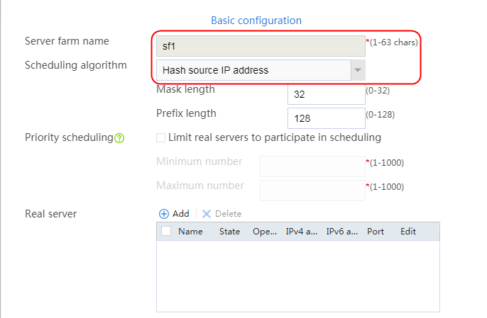
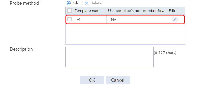
3. Click OK.
Configuring real servers
1. Navigate to the LB > Application Load Balancing > Server Farms page.
2. Edit server farm sf1, and click Add to create a real server. Specify the real server name as rs1, IP address as 192.168.1.1, and port number as 80.
Figure 307 Adding a real server

Figure 308 Creating a real server

3. Click OK.
4. Create real server rs2 in the same way rs1 is created:
a. Navigate to the LB > Application Load Balancing > Server Farms page.
b. Edit server farm sf2 to add a real server.
c. Create real server rs2 as shown in the figure above. Configure its IPv4 address as 192.168.1.2 and port number as 80.
5. Create real server rs3 in the same way rs1 is created:
a. Navigate to the LB > Application Load Balancing > Server Farms page.
b. Edit server farm sf2 to add a real server.
c. Create real server rs3 as shown in the figure above. Configure its IPv4 address as 192.168.1.3 and port number as 80.
Figure 309 Server farm information
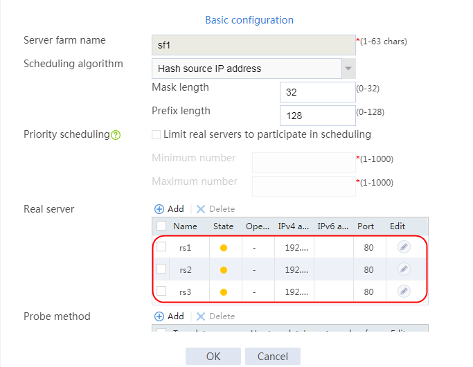
Configuring an LB action
1. Navigate to the LB > Application Load Balancing > Advanced Policies > Action page.
2. Click Create to create an LB action. Specify the type as HTTP and the primary server farm as sf1.
3. Click Create for Header insertion. In the Create Header Insertion dialog box, specify the direction as Request, and set the header name to http-certification-insert and the value to %{x509v} (certificate version).
Figure 310 Creating LB action la1
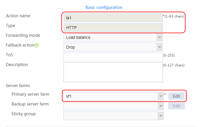
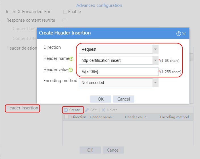

4. Click OK.
Configuring an LB policy
1. Navigate to the LB > Application Load Balancing > Advanced Policies > Load Balancing Policy page.
2. Click Create to create an LB policy named lp, and specify the type as HTTP and the default action as la1.
Figure 311 Creating an LB policy
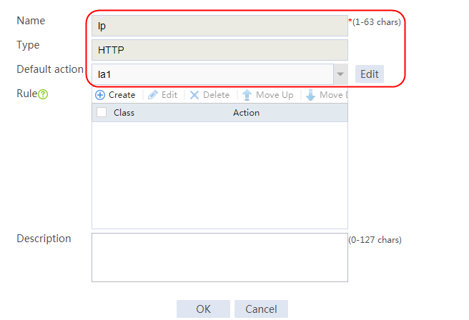
3. Click OK.
Configuring a virtual server
1. Navigate to the LB > Application Load Balancing > Virtual Servers page.
2. Click Create to create a virtual server named vs. Specify the type as HTTPS, virtual IP address as 61.159.4.100, and port number as 443. Specify SSL server policy ssl and LB policy lp, and enable the virtual server feature.
Figure 312 Creating a virtual server
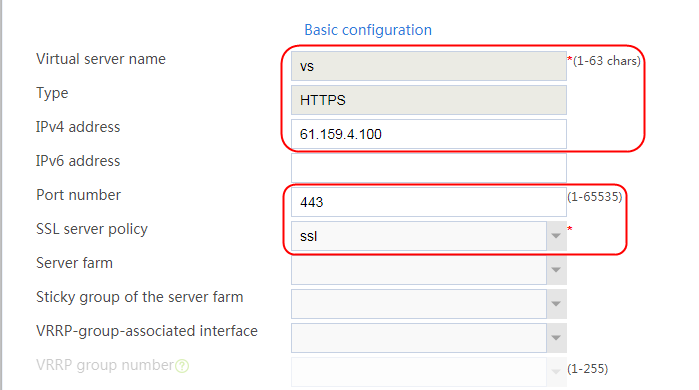
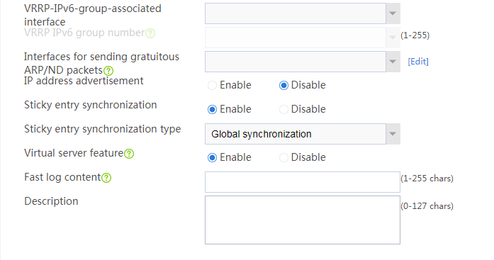
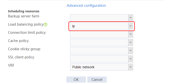
3. Click OK.
Verifying the configuration
Without a correct certificate imported to the host
From the packet captured on the host, you can see that the device requests a certificate (Certificate Request) from the host, but the host without a correct certificate imported cannot send the certificate. As a result, the SSL handshake fails and the host fails to accesses the HTTP server through https://61.159.4.100.
Figure 313 Packets captured on the host
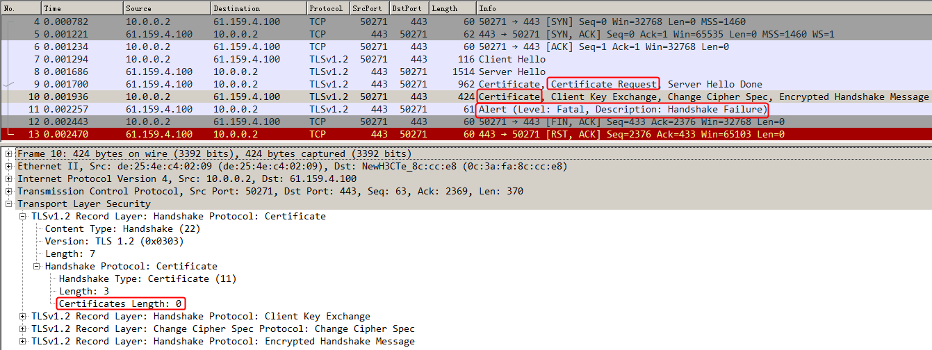
With a correct certificate imported to the host
You can see from the packet captured on the host that the device requests a certificate (Certificate Request) from the host, and the host responds with the correct certificate. As a result, the SSL handshake is successful, and the host accesses the HTTP server through https://61.159.4.100 successfully.
Figure 314 Packets captured on the host

Viewing captured packet information on the server
The HTTP request packet is inserted with the field http-certification-insert and the value of the certificate version.
Figure 315 Packets captured on the server
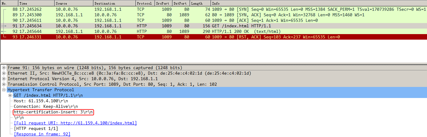
Configuration files
#
nqa template http t1
expect status 200
#
pki domain ca
public-key rsa general name ca length 2048
undo crl check enable
#
ssl server-policy ssl
pki-domain ca
ciphersuite dhe_rsa_aes_256_cbc_sha rsa_aes_256_cbc_sha dhe_rsa_aes_128_cbc_sha rsa_aes_128_cbc_sha rsa_aes_128_cbc_sha256 rsa_aes_
256_cbc_sha256 dhe_rsa_aes_128_cbc_sha256 dhe_rsa_aes_256_cbc_sha256 ecdhe_rsa_aes_128_cbc_sha256 ecdhe_rsa_aes_256_cbc_sha384 ecdhe
_rsa_aes_128_gcm_sha256
ciphersuite ecdhe_rsa_aes_256_gcm_sha384 ecdhe_ecdsa_aes_128_cbc_sha256 ecdhe_ecdsa_aes_256_cbc_sha384 ecdhe_ecdsa_aes_128_gcm_sha2
56 ecdhe_ecdsa_aes_256_gcm_sha384 tls_aes_128_gcm_sha256 tls_aes_256_gcm_sha384 tls_chacha20_poly1305_sha256 tls_aes_128_ccm_sha256
tls_aes_128_ccm_8_sha256
client-verify enable
certificate-chain-sending enable
version ssl3.0 disable
version tls1.0 disable
#
server-farm sf1
predictor hash address source
probe t1
success-criteria at-least 1
real-server rs1 port 80
success-criteria at-least 1
real-server rs2 port 80
success-criteria at-least 1
real-server rs3 port 80
success-criteria at-least 1
#
loadbalance action la1 type http
server-farm sf1
header insert request name http-certification-insert value %{x509v}
#
loadbalance policy lp type http
default-class action la1
#
real-server rs1
ip address 192.168.1.1
#
real-server rs2
ip address 192.168.1.2
#
real-server rs3
ip address 192.168.1.3
#
virtual-server vs type http
port 443
virtual ip address 61.159.4.100
lb-policy lp
ssl-server-policy ssl
sticky-sync enable global
service enable
#
Example: Configuring bidirectional SSL authentication
Network configuration
The LB device provides bidirectional SSL authentication services for users and the internal HTTPS servers. It requires identity authentication for both the server and the host. Only permitted clients are allowed to access the server.
The LB device encrypts and decrypts the HTTPS access request from the host to three servers Server A, Server B, and Server C that can all provide HTTPS services. The host traffic will be load-shared among the three servers.
Figure 316 Network diagram

Analysis
To implement bidirectional SSL authentication, complete the following configuration on the LB device:
· Import the CA certificate and local certificate to the LB device.
· Create an SSL server policy and an SSL client policy on the LB device.
Software versions used
This configuration example was created and verified on Feature 1160P16 of L1070.
Restrictions and guidelines
When you configure bidirectional SSL authentication, follow these restrictions and guidelines:
· Make sure a route is available from the host to the LB device.
· You must first apply for the correct certificate, and then upload the certificate to the LB device through FTP or TFTP.
· After configuring the virtual server, you need to enable the virtual server feature.
· Configure the port number of the virtual server as 443, and the port number of the real server as 443.
· Import the same local certificate as the LB device to the server.
· When the SSL server policy or SSL client policy is modified, you must disable and enable the virtual server again to make the configuration effective.
· After creating an SSL server policy, use relevant commands to manually enable the SSL server to send the complete certificate chain during SSL negotiation.
Procedures
Perform the following configuration on the LB device.
Assigning IP addresses to interfaces
Details not shown.
Creating a PKI domain and disabling CRL checking
1. Navigate to the Objects > KPI > Certificates page.
2. Click Create to create a PKI domain named ca, and disable CRL checking.
Figure 317 Creating a PKI domain

3. Click OK.
Importing the CA certificate and local certificate into the PKI domain
1. Select the created PKI domain ca, and click Import Certificate.
Figure 318 Importing a certificate

2. Specify the certificate type as CA certificate, click Select file, and select the CA certificate file.
Figure 319 Importing a CA certificate

3. Click OK and then click Yes to confirm the fingerprint information.
Figure 320 Certificate fingerprint information

4. Specify the certificate type as Local certificate, click Select file, select the local certificate file, and enter the password for certificate.
Figure 321 Importing a local certificate

5. Click OK.
Creating an SSL server policy
1. Navigate to the Objects > SSL > Server Policies page.
2. Click Create to create an SSL server policy named ssl_server, and specify the PKI domain as ca.
Figure 322 Creating an SSL server policy
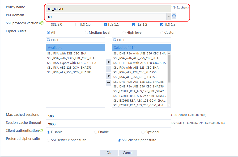
3. Click OK.
4. Execute the following commands to manually enable the SSL server to send a complete certificate chain during SSL negotiation (the configuration is not supported on the Web interface):
[Sysname]ssl server-policy ssl_server
[Sysname-ssl-server-policy-ssl]certificate-chain-sending enable
Creating an SSL client policy
1. Navigate to the Objects > SSL > Client Policies page.
2. Click Create to create an SSL server policy named ssl_client, and specify the PKI domain as ca.
Figure 323 Creating an SSL client policy
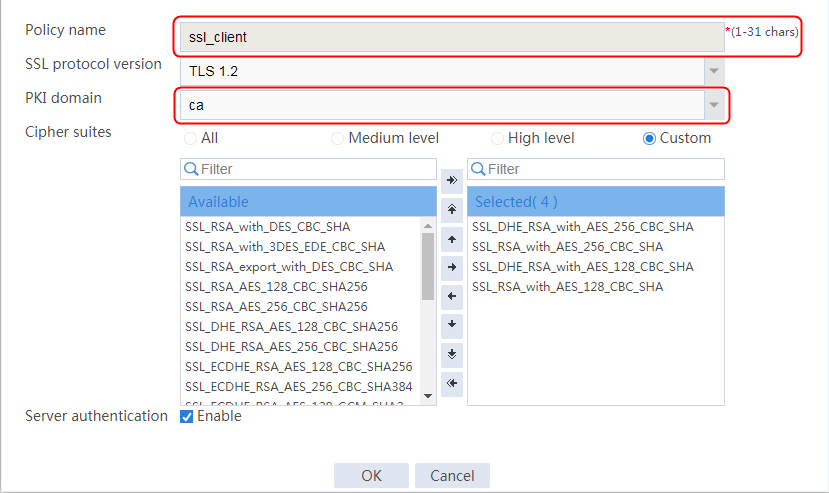
Creating a health monitoring template
1. Navigate to the LB > Global Configuration > Health Monitoring page.
2. Click Create to create a template named t1, and specify the type as HTTPS, the SSL client policy as ssl_client, and the expected status code as 200.
Figure 324 Creating a health monitoring template
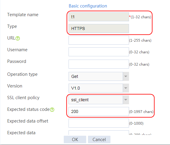
3. Click OK.
Configuring a server farm
1. Navigate to the LB > Application Load Balancing > Server Farms page.
2. Click Create to create a server farm named sf1. Specify the scheduling algorithm as Hash source IP address and probe method as t1.
Figure 325 Creating a server farm


3. Click OK.
Configuring the real server
1. Navigate to the LB > Application Load Balancing > Server Farms page.
2. Edit server farm sf1, and click Add to create a real server. Specify the real server name as rs1, IP address as 192.168.1.1, and port number as 443.
Figure 326 Adding a real server

Figure 327 Creating a real server
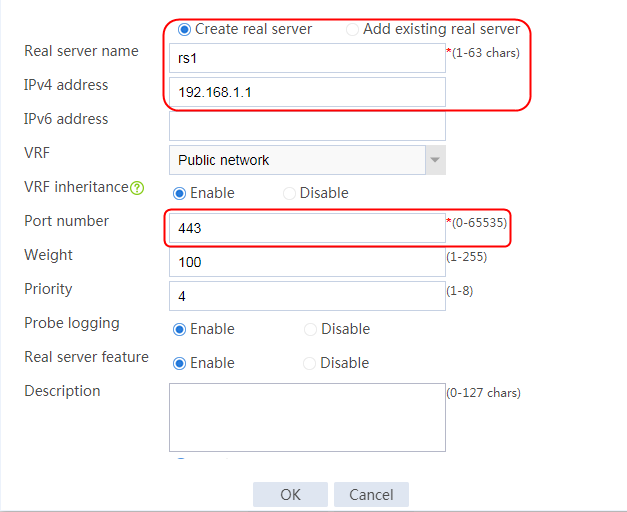
3. Click OK.
4. Create real server rs2 in the same way rs1 is created:
a. Navigate to the LB > Application Load Balancing > Server Farms page.
b. Edit server farm sf2 to add a real server.
c. Create real server rs2 as shown in the figure above. Configure its IPv4 address as 192.168.1.2 and port number as 443.
5. Create real server rs3 in the same way rs1 is created:
a. Navigate to the LB > Application Load Balancing > Server Farms page.
b. Edit server farm sf2 to add a real server.
c. Create real server rs3 as shown in the figure above. Configure its IPv4 address as 192.168.1.3 and port number as 443.
Figure 328 Server farm information
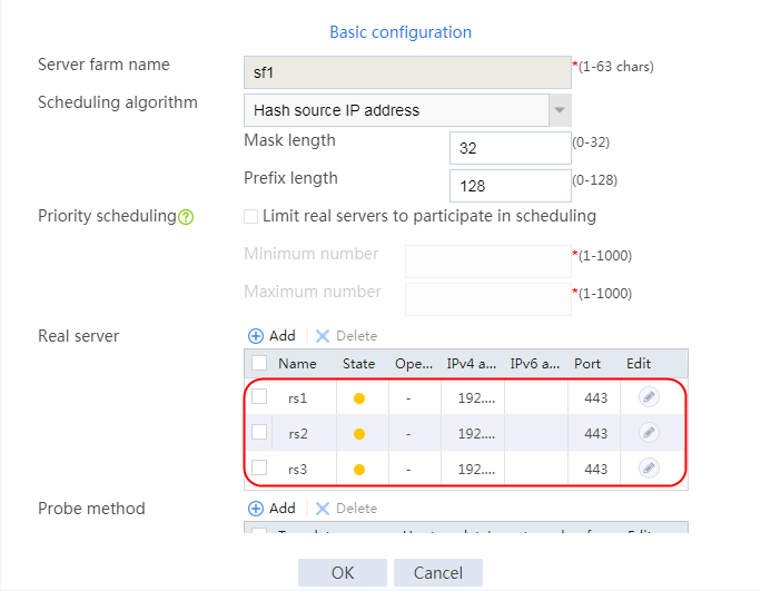
Configuring a virtual server
1. Navigate to the LB > Application Load Balancing > Virtual Servers page.
2. Click Create to create a virtual server named vs. Specify the type as HTTPS, virtual IP address as 61.159.4.100, default server farm as sf1, and port number as 443. Specify SSL server policy ssl_server and SSL client policy ssl_client, and enable the virtual server feature.
Figure 329 Creating a virtual server
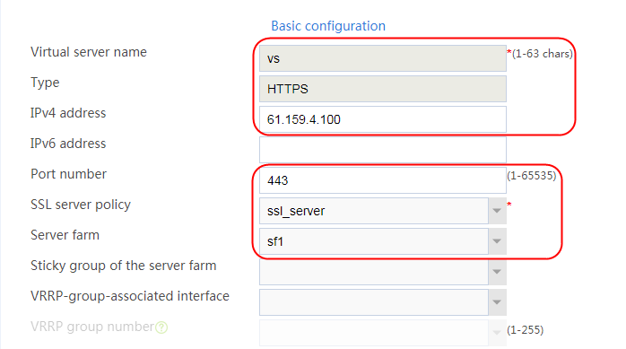
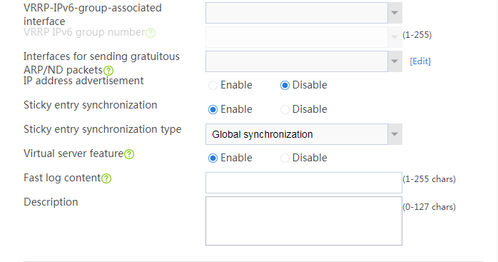
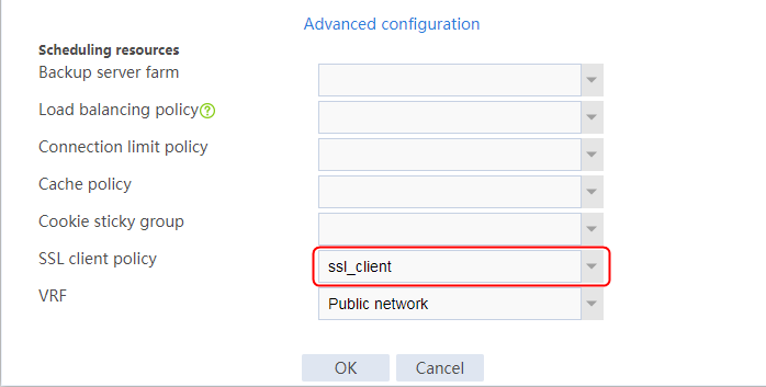
3. Click OK.
Verifying the configuration
The host accesses the HTTP server through https://61.159.4.100 successfully. The packets exchanged between the host and the device are in encrypted form. View captured packet information on the host.
Figure 330 Packets captured on the host
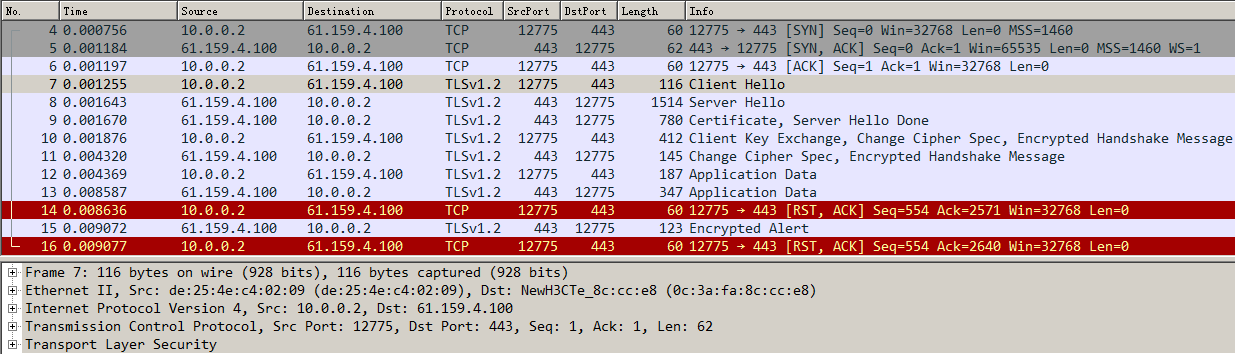
The packets exchanged between the device and the server are in encrypted form. View captured packet information on the server.
Figure 331 Packets captured on the server
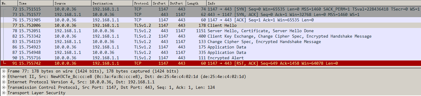
Configuration files
#
nqa template https t1
expect status 200
ssl-client-policy ssl_client
#
pki domain ca
public-key rsa general name ca length 2048
undo crl check enable
#
ssl server-policy ssl_server
pki-domain ca
ciphersuite dhe_rsa_aes_256_cbc_sha rsa_aes_256_cbc_sha dhe_rsa_aes_128_cbc_sha rsa_aes_128_cbc_sha rsa_aes_128_cbc_sha256 rsa_aes_
256_cbc_sha256 dhe_rsa_aes_128_cbc_sha256 dhe_rsa_aes_256_cbc_sha256 ecdhe_rsa_aes_128_cbc_sha256 ecdhe_rsa_aes_256_cbc_sha384 ecdhe
_rsa_aes_128_gcm_sha256
ciphersuite ecdhe_rsa_aes_256_gcm_sha384 ecdhe_ecdsa_aes_128_cbc_sha256 ecdhe_ecdsa_aes_256_cbc_sha384 ecdhe_ecdsa_aes_128_gcm_sha2
56 ecdhe_ecdsa_aes_256_gcm_sha384 tls_aes_128_gcm_sha256 tls_aes_256_gcm_sha384 tls_chacha20_poly1305_sha256 tls_aes_128_ccm_sha256
tls_aes_128_ccm_8_sha256
certificate-chain-sending enable
version ssl3.0 disable
version tls1.0 disable
#
ssl client-policy ssl_client
pki-domain ca
#
server-farm sf1
predictor hash address source
probe t1
success-criteria at-least 1
real-server rs1 port 443
success-criteria at-least 1
real-server rs2 port 443
success-criteria at-least 1
real-server rs3 port 443
success-criteria at-least 1
#
real-server rs1
ip address 192.168.1.1
#
real-server rs2
ip address 192.168.1.2
#
real-server rs3
ip address 192.168.1.3
#
virtual-server vs type http
port 443
virtual ip address 61.159.4.100
default server-farm sf1
ssl-server-policy ssl_server
ssl-client-policy ssl_client
sticky-sync enable global
service enable
#
Example: Configuring dual certificates for an SSL server policy
Network configuration
SSL offloading enables the LB device to provide SSL encryption and decryption services for the Web server on the internal network, and provide secure access (SSL encryption) to the Web server externally. The internal Web server only needs to process services without performing SSL encryption and decryption, improving the processing capacity of the server.
Configure both RSA and ECC certificates for the LB device. The host can establish an SSL connection with the same virtual server on the LB device for transmitting encrypted data by using the RSA or ECC encryption algorithm.
The LB device encrypts and decrypts the HTTPS access request from the host to three servers Server A, Server B, and Server C in the public network that can all provide HTTP services. The host traffic will be load-shared among the three servers.
Figure 332 Network diagram
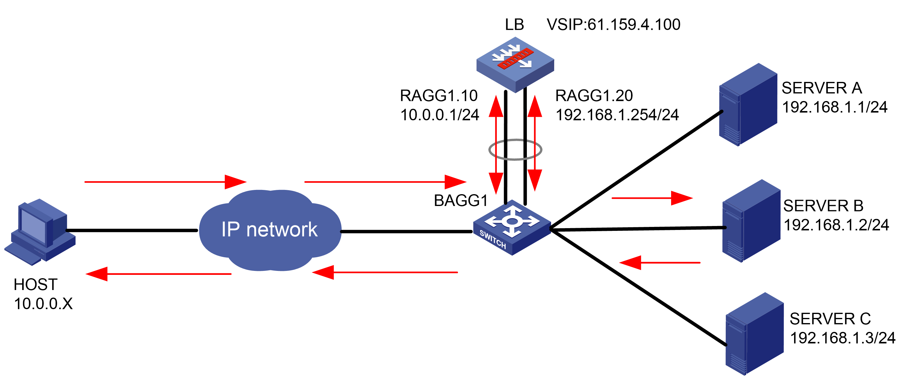
Analysis
To configure dual certificates for an SSL server policy, complete the following configuration on the LB device:
· Import the CA and local certificates (RSA certificate and ECC certificate) to the LB device, create an SSL server policy on the LB device, and specify PKI domains associated with the two certificates.
· Configure server farm, real server, and virtual server settings.
· The HTTPS requests from the client can be encrypted by using the RSA and ECC algorithms to access the virtual server successfully.
Software versions used
This configuration example was created and verified on Feature 1160P16 of L1070.
Restrictions and guidelines
When you configure dual certificates for an SSL server policy, follow these restrictions and guidelines:
· Make sure a route is available from the host to the LB device.
· You must first apply for the correct certificate, and then upload the certificate to the LB device through FTP or TFTP.
· After creating an SSL server policy, use relevant commands to manually enable the SSL server to send the complete certificate chain during SSL negotiation.
Procedures
Perform the following configuration on the LB device.
Assigning IP addresses to interfaces
Details not shown.
Creating a PKI domain and disabling CRL checking
1. Navigate to the Objects > KPI > Certificates page.
2. Click Create to create a PKI domain named ca_rsa, and disable CRL checking.
Figure 333 Creating a PKI domain
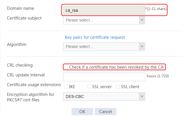
3. Click OK.
4. Create PKI domain ca_ecc in the same way PKI domain ca_rsa is created.
Importing the CA and local certificates to the PKI domains
1. Select the created PKI domain ca_rsa, and click Import Certificate.
Figure 334 Importing a certificate
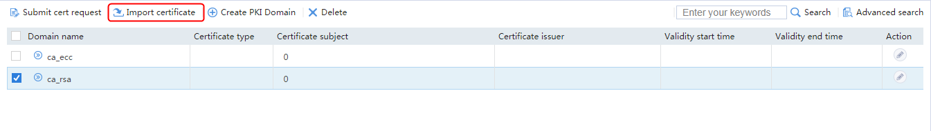
2. Specify the certificate type as CA certificate, click Select file, and select the CA certificate file.
Figure 335 Importing a CA certificate
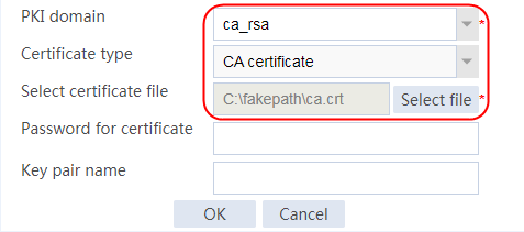
3. Click OK and then click Yes to confirm the fingerprint information.
Figure 336 Certificate fingerprint information

4. Specify the certificate type as Local certificate, click Select file, select the local certificate file, import the RSA certificate, and enter the password for certificate.
Figure 337 Importing a local certificate
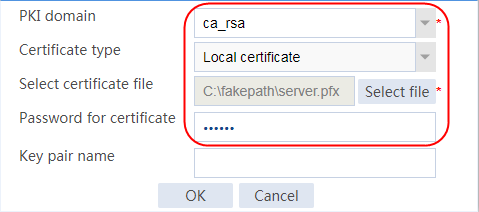
5. Click OK.
6. Import the CA and local certificates to PKI domain ca_ecc in the same way. Select the created PKI domain ca_ecc, and import the CA certificate and the local certificate (ECC certificate), respectively.
Creating an SSL server policy
1. Navigate to the Objects > SSL > Server Policies page.
2. Click Create to create an SSL server policy named ssl, and specify the PKI domain as ca_rsa.
3. Click the plus sign next to the PKI domain field to specify PKI domain ca_ecc.
Figure 338 Creating an SSL server policy
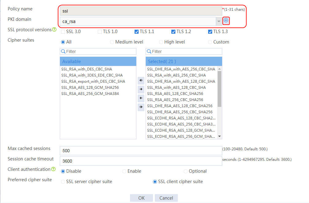
Figure 339 Selecting the second PKI domain
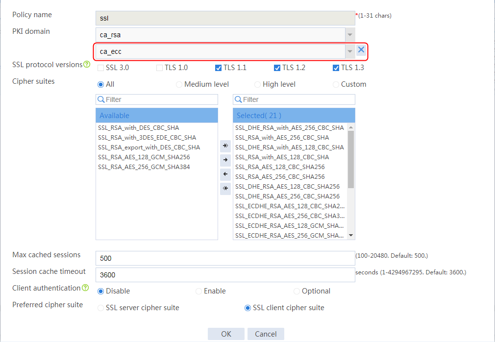
4. Click OK.
5. Execute the following commands to manually enable the SSL server to send a complete certificate chain during SSL negotiation (the configuration is not supported on the Web interface):
[Sysname]ssl server-policy ssl
[Sysname-ssl-server-policy-ssl]certificate-chain-sending enable
Creating a health monitoring template
1. Navigate to the LB > Global Configuration > Health Monitoring page.
2. Click Create to create a template named t1, specify the type as HTTP, and set the expected status code to 200.
Figure 340 Creating a health monitoring template
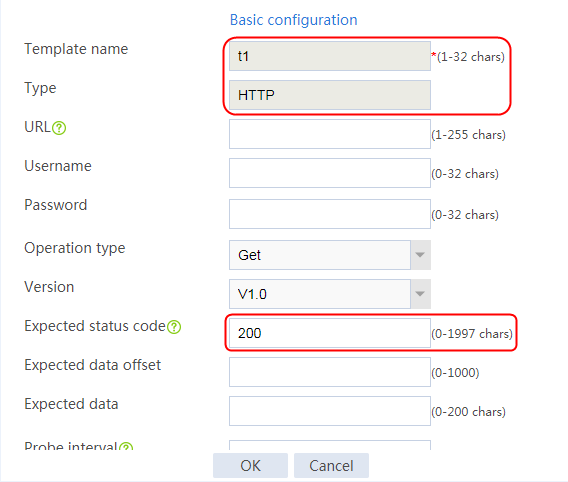
3. Click OK.
Configuring a server farm
1. Navigate to the LB > Application Load Balancing > Server Farms page.
2. Click Create to create a server farm named sf1. Specify the scheduling algorithm as Hash source IP address and probe method as t1.
Figure 341 Creating a server farm

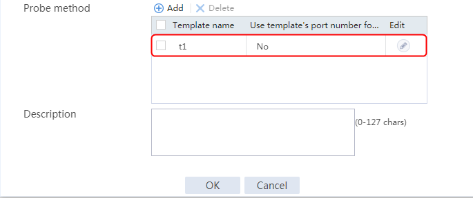
3. Click OK.
Configuring the real server
1. Navigate to the LB > Application Load Balancing > Server Farms page.
2. Edit server farm sf1, and click Add to create a real server. Specify the real server name as rs1, IP address as 192.168.1.1, and port number as 80.
Figure 342 Adding a real server
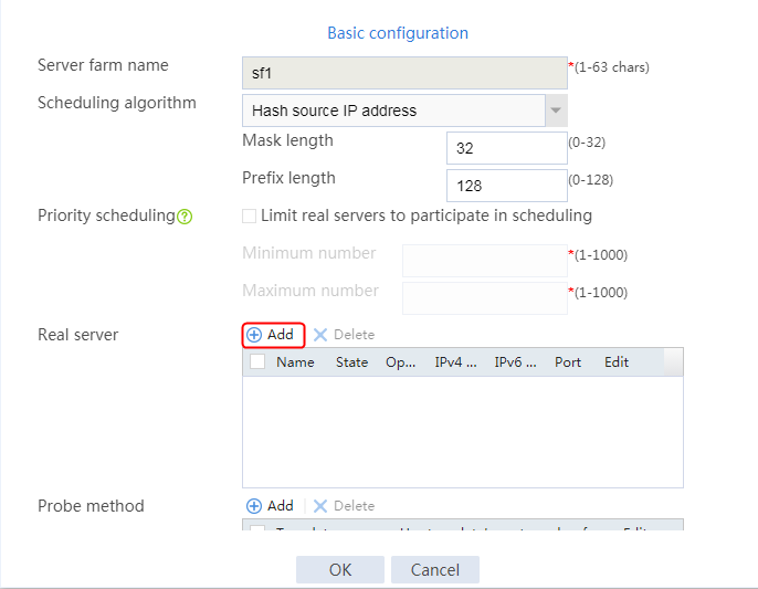
Figure 343 Creating a real server

3. Click OK.
4. Create real servers rs2 and rs3 in the same way rs1 is created. Configure the IPv4 addresses as 192.168.1.2 and 192.168.1.3 and port number as 80 for real servers rs2 and rs3, respectively.
Figure 344 Server farm information

Configuring a virtual server
1. Navigate to the Policies > LB > Server Load Balancing > Virtual Servers page.
2. Click Create to create a virtual server named vs. Specify the type as HTTPS, virtual IP address as 61.159.4.100, default server farm as sf1, and port number as 443. Specify SSL policy ssl, and enable the virtual server feature.
Figure 345 Creating a virtual server

3. Click OK.
Verifying the configuration
The host uses the RSA encryption algorithm to access the virtual server through https://61.159.4.100 successfully. View captured packet information on the host. The server hello packet shows that the negotiated algorithm is the RSA encryption algorithm.
Figure 346 Packets captured on the host
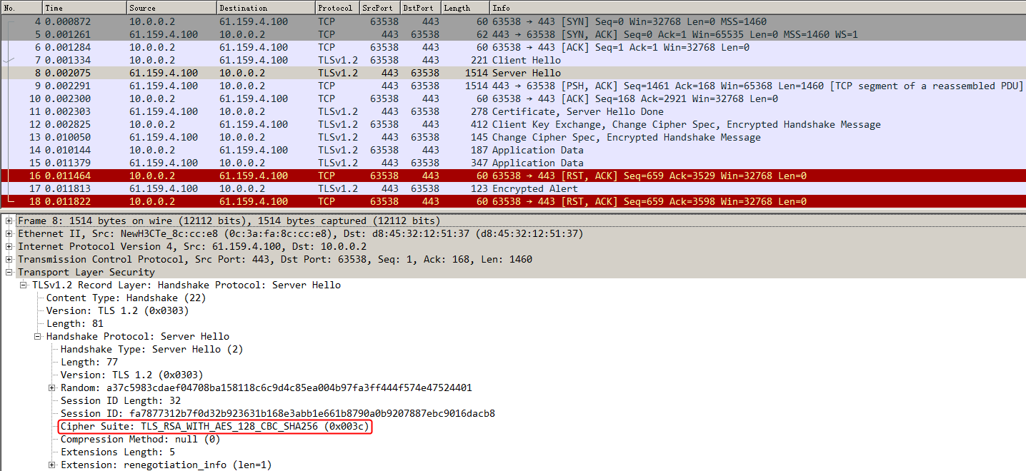
The host uses the ECC encryption algorithm to access the virtual server through https://61.159.4.100 successfully. View captured packet information on the host. The server hello packet shows that the negotiated algorithm is the ECC encryption algorithm.
Figure 347 Packets captured on the host
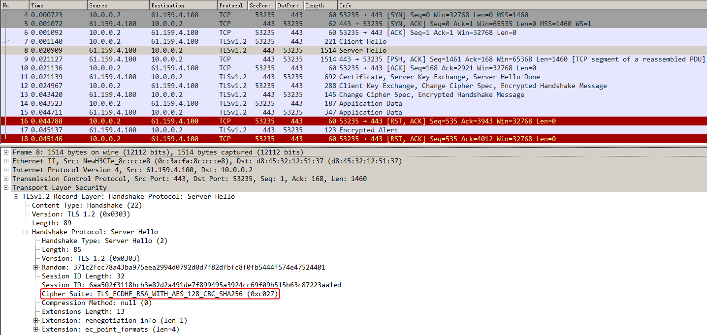
Configuration files
#
nqa template http t1
expect status 200
#
pki domain ca_ecc
public-key ecdsa name ca-ecc secp256r1
undo crl check enable
#
pki domain ca_rsa
public-key rsa general name ca-rsa length 2048
undo crl check enable
#
ssl server-policy ssl
pki-domain ca_rsa ca_ecc
ciphersuite dhe_rsa_aes_256_cbc_sha rsa_aes_256_cbc_sha dhe_rsa_aes_128_cbc_sha rsa_aes_128_cbc_sha rsa_aes_128_cbc_sha256 rsa_aes_
256_cbc_sha256 dhe_rsa_aes_128_cbc_sha256 dhe_rsa_aes_256_cbc_sha256 ecdhe_rsa_aes_128_cbc_sha256 ecdhe_rsa_aes_256_cbc_sha384 ecdhe
_rsa_aes_128_gcm_sha256
ciphersuite ecdhe_rsa_aes_256_gcm_sha384 ecdhe_ecdsa_aes_128_cbc_sha256 ecdhe_ecdsa_aes_256_cbc_sha384 ecdhe_ecdsa_aes_128_gcm_sha2
56 ecdhe_ecdsa_aes_256_gcm_sha384 tls_aes_128_gcm_sha256 tls_aes_256_gcm_sha384 tls_chacha20_poly1305_sha256 tls_aes_128_ccm_sha256
tls_aes_128_ccm_8_sha256
certificate-chain-sending enable
version ssl3.0 disable
version tls1.0 disable
undo version gm-tls1.1 disable
#
server-farm sf1
predictor hash address source
probe t1
success-criteria at-least 1
real-server rs1 port 80
success-criteria at-least 1
real-server rs2 port 80
success-criteria at-least 1
real-server rs3 port 80
success-criteria at-least 1
#
real-server rs1
ip address 192.168.1.1
#
real-server rs2
ip address 192.168.1.2
#
real-server rs3
ip address 192.168.1.3
#
virtual-server vs type http
port 443
virtual ip address 61.159.4.100
default server-farm sf1
ssl-server-policy ssl
sticky-sync enable global
service enable
#
Example: Configuring SNI-based certificate selection from SSL server policies
Network configuration
SSL offloading enables the LB device to provide SSL encryption and decryption services for the Web server on the internal network, and provide secure access (SSL encryption) to the Web server externally. The internal Web server only needs to process services without performing SSL encryption and decryption, improving the processing capacity of the server.
Enable the LB device to use SSL server policies to match SNIs in user requests, so that the server can return the user with the certificates associated with the matching SSL server policies. The LB device will insert domain names into SSL handshake packets, enabling the server to return the domain name-associated certificates to the client.
The LB device encrypts and decrypts the HTTPS access request from the host to three servers Server A, Server B, and Server C in the public network that can all provide HTTP services. The host traffic will be load-shared among the three servers.
Figure 348 Network diagram

Analysis
To configure SNI-based certificate selection from SSL server policies, complete the following configuration on the LB device:
· Import CA and local certificates to the LB device, create a default SSL server policy on the LB device, and configure SSL server policies to match specific SNIs.
· Configure server farm, real server, and virtual server settings.
· The host can send HTTPS requests carrying different SNIs to the virtual server successfully and can obtain the associated certificates.
Software versions used
This configuration example was created and verified on Feature 1160P16 of L1070.
Restrictions and guidelines
When you configure SNI-based certificate selection from SSL server policies, follow these restrictions and guidelines:
· Make sure a route is available from the host to the LB device.
· You must first apply for the correct certificates, and then upload the certificates to the LB device through FTP or TFTP. Import the certificate for the SSL server policy corresponding to each SNI.
· In the same view, you cannot configure multiple identical SSL server policies.
· In the same view, you cannot configure multiple SSL server policies with the same SNI.
· Configure the default SSL server policy to match user requests without carrying a SNI.
· When the SSL server policy is modified, you must disable and enable the virtual server again to make the configuration effective.
· After creating an SSL server policy, use relevant commands to manually enable the SSL server to send the complete certificate chain during SSL negotiation.
· After creating an SSL server policy, use relevant commands to manually configure SNIs and the SSL server policies.
Procedures
Perform the following configuration on the LB device.
Assigning IP addresses to interfaces
Details not shown.
Creating PKI domains and disabling CRL checking
1. Navigate to the Objects > KPI > Certificates page.
2. Click Create to create a PKI domain named ca_default, and disable CRL checking.
Figure 349 Creating a PKI domain
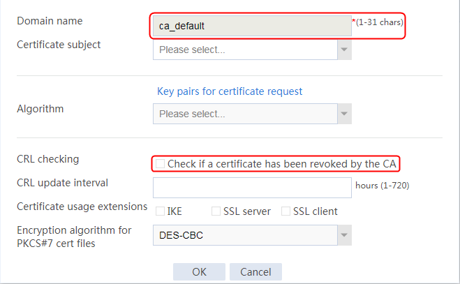
3. Click OK.
4. Create PKI domains ca_aaa and ca_bbb in the same way PKI domain ca_default is created.
Importing CA and local certificates into PKI domains
1. Select the created PKI domain ca_default, and click Import Certificate.
Figure 350 Importing a certificate
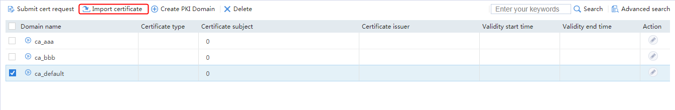
2. Specify the certificate type as CA certificate, click Select file, and select the CA certificate file.
Figure 351 Importing a CA certificate
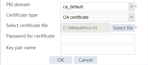
3. Click OK and then click Yes to confirm the fingerprint information.
Figure 352 Certificate fingerprint information
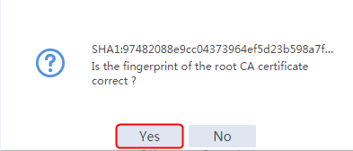
4. Specify the certificate type as Local certificate, click Select file, select the local certificate file, and enter the password for certificate.
Figure 353 Importing a local certificate
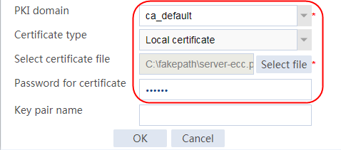
5. Click OK.
6. Import the CA and local certificates to PKI domains ca_aaa and ca_bbb in the same way.
Creating SSL server policies
1. Navigate to the Objects > SSL > Server Policies page.
2. Click Create to create an SSL server policy named ssl_default, and specify the PKI domain as ca_default.
Figure 354 Creating an SSL server policy
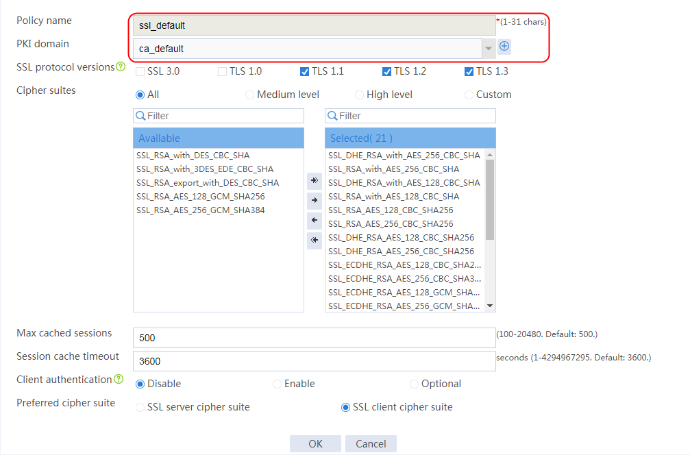
3. Click OK.
4. Create SSL server policies ssl_aaa and ssl_bbb in the same way SSL server policy ssl_default is created.
5. Execute the following commands to manually enable the SSL server to send a complete certificate chain during SSL negotiation (the configuration is not supported on the Web interface):
[Sysname] ssl server-policy ssl_default
[Sysname-ssl-server-policy-ssl_default] certificate-chain-sending enable
[Sysname-ssl-server-policy-ssl_default] quit
[Sysname] ssl server-policy ssl_aaa
[Sysname-ssl-server-policy-ssl_aaa] certificate-chain-sending enable
[Sysname-ssl-server-policy-ssl_aaa] quit
[Sysname] ssl server-policy ssl_bbb
[Sysname-ssl-server-policy-ssl_bbb] certificate-chain-sending enable
[Sysname-ssl-server-policy-ssl_bbb] quit
Creating a health monitoring template
1. Navigate to the LB > Global Configuration > Health Monitoring page.
2. Click Create to create a template named t1, specify the type as HTTP, and set the expected status code to 200.
Figure 355 Creating a health monitoring template
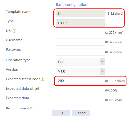
3. Click OK.
Configuring a server farm
1. Navigate to the LB > Application Load Balancing > Server Farms page.
2. Click Create to create a server farm named sf1. Specify the scheduling algorithm as Hash source IP address and probe method as t1.
Figure 356 Creating a server farm


3. Click OK.
Configuring real servers
1. Navigate to the LB > Application Load Balancing > Server Farms page.
2. Edit server farm sf1, and click Add to create a real server. Specify the real server name as rs1, IP address as 192.168.1.1, and port number as 80.
Figure 357 Adding a real server

Figure 358 Creating a real server

3. Click OK.
4. Create real server rs2 in the same way rs1 is created:
a. Navigate to the LB > Application Load Balancing > Server Farms page.
b. Edit server farm sf2 to add a real server.
c. Create real server rs2 as shown in the figure above. Configure its IPv4 address as 192.168.1.2 and port number as 80.
5. Create real server rs3 in the same way rs1 is created:
a. Navigate to the LB > Application Load Balancing > Server Farms page.
b. Edit server farm sf2 to add a real server.
c. Create real server rs3 as shown in the figure above. Configure its IPv4 address as 192.168.1.3 and port number as 80.
Figure 359 Server farm information

Configuring a virtual server
1. Navigate to the LB > Application Load Balancing > Virtual Servers page.
2. Click Create to create a virtual server named vs. Specify the type as HTTPS, virtual IP address as 61.159.4.100, default server farm as sf1, and port number as 443. Specify SSL policy ssl, and enable the virtual server feature.
Figure 360 Creating a virtual server
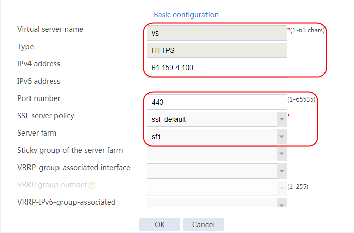
3. Click OK.
Configuring SNIs
Use the following commands to manually configure SNIs for the virtual server:
[Sysname]virtual-server vs
[Sysname-vs-http-vs]ssl-server-policy ssl_aaa sni www.aaa.com
[Sysname-vs-http-vs]ssl-server-policy ssl_bbb sni www.bbb.com
When the SSL server policy is modified, you must disable and enable the virtual server again to make the configuration effective.
Verifying the configuration
Sending a request without carrying an SNI
The host accesses the virtual server through https://61.159.4.100 (without carrying the SNI information) successfully. Capture packets on the host to verify the following information:
· The client Hello packet has no SNI information.
· The server Hello packet shows that the certificate of the default SSL server policy ssl_default is used.
· The subjectPublicKey in the server Hello packet is consistent with the public key of the local key pair ca_default (configured on the Objects > Public Key Management > Local Key Pairs page), which means that the certificate corresponding to SSL server policy ssl_default is used.
Figure 361 Packets captured on the host (client Hello)
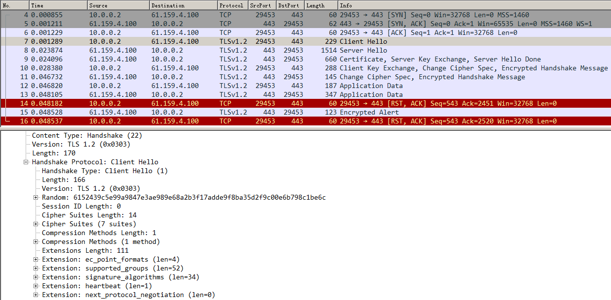
Figure 362 Packets captured on the host (server Hello)
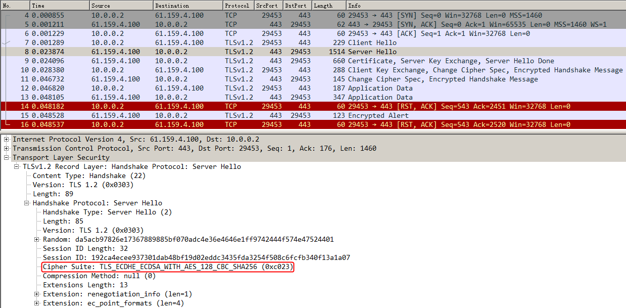
Figure 363 Packets captured on the host (subjectPublicKey)

Figure 364 Device public key
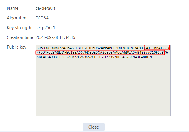
Sending a request carrying SNI https://www.aaa.com
The host accesses the virtual server through https://www.aaa.com (SNI information) successfully. Capture packets on the host to verify the following information:
· The client Hello packet has SNI information www.aaa.com.
· The server Hello packet shows that the certificate of SSL server policy ssl_aaa is used.
· The subjectPublicKey in the server Hello packet is consistent with the public key of the local key pair ca_aaa (configured on the Objects > Public Key Management > Local Key Pairs page), which means that the certificate corresponding to SSL server policy ssl_aaa is used.
Figure 365 Packets captured on the host (client Hello)
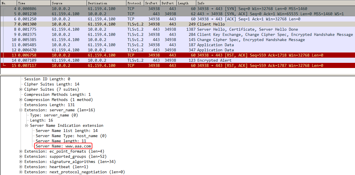
Figure 366 Packets captured on the host (server Hello)
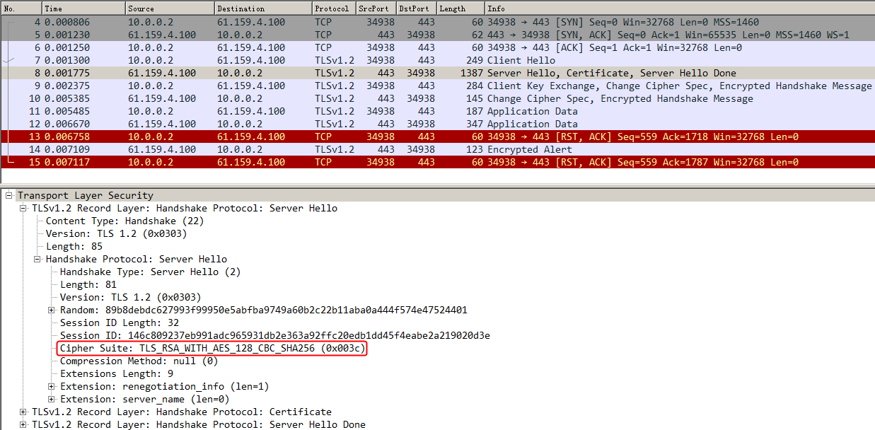
Figure 367 Packets captured on the host (subjectPublicKey)
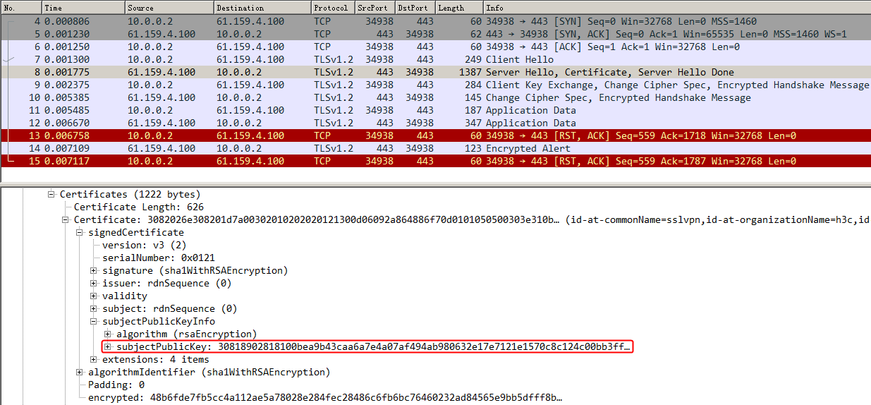
Figure 368 Device public key
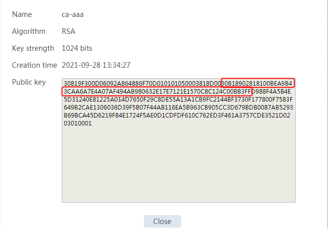
Sending a request carrying SNI https://www.bbb.com
The host accesses the virtual server through https://www.aaa.com (SNI information) successfully. Capture packets on the host to verify the following information:
· The client Hello packet has SNI information www.bbb.com.
· The server Hello packet shows that the certificate of SSL server policy ssl_bbb is used.
· The subjectPublicKey in the server Hello packet is consistent with the public key of the local key pair ca_bbb (configured on the Objects > Public Key Management > Local Key Pairs page), which means that the certificate corresponding to SSL server policy ssl_bbb is used.
Figure 369 Packets captured on the host (client Hello)
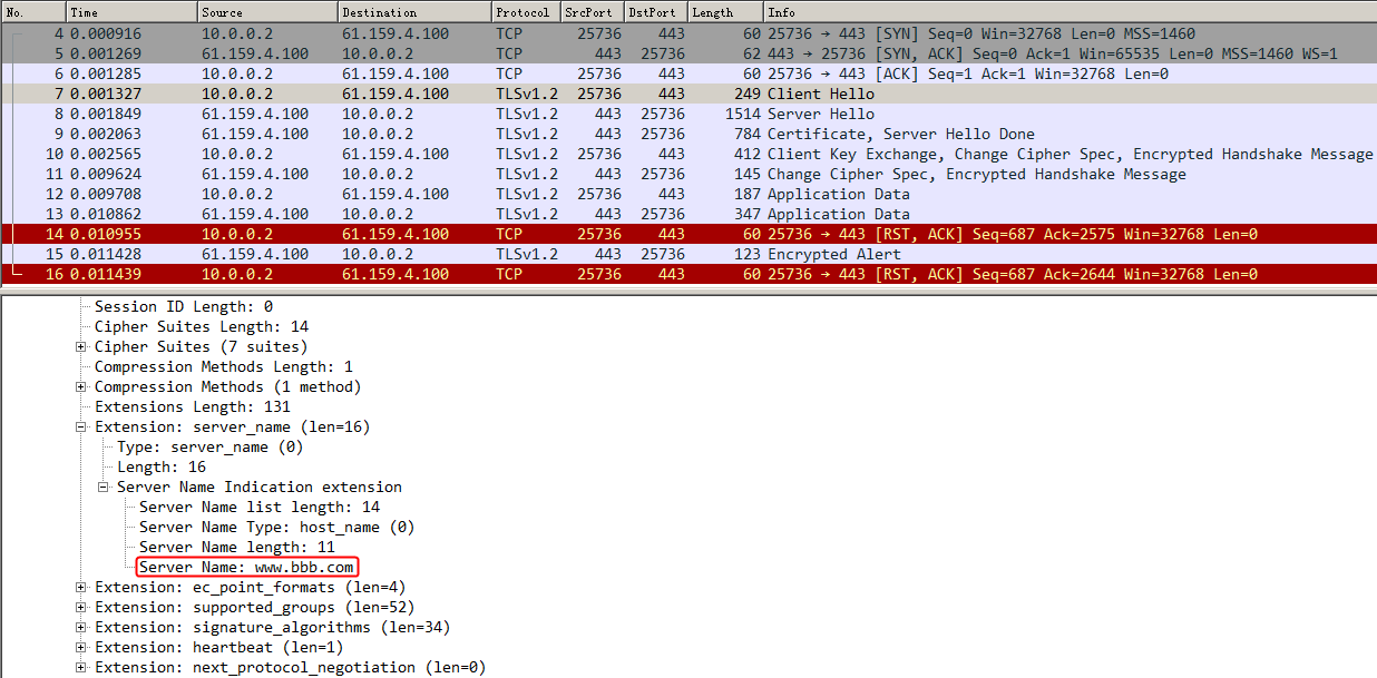
Figure 370 Packets captured on the host (server Hello)
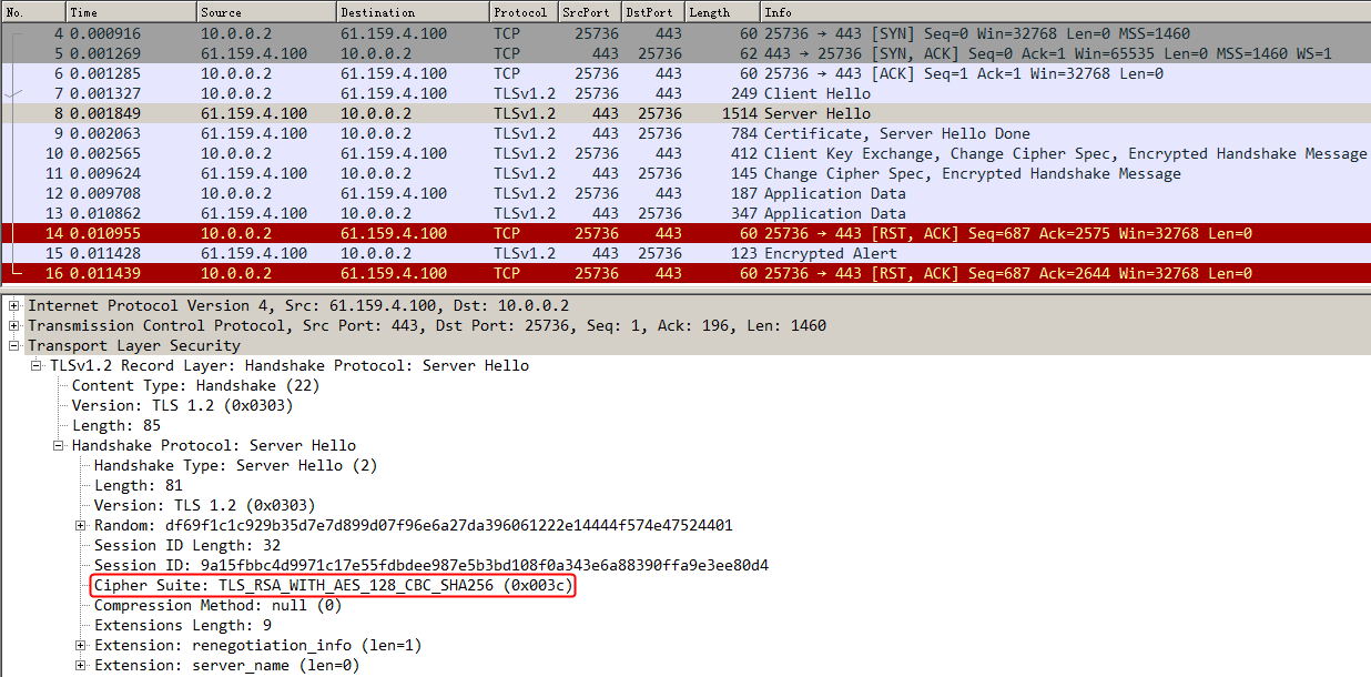
Figure 371 Packets captured on the host (subjectPublicKey)
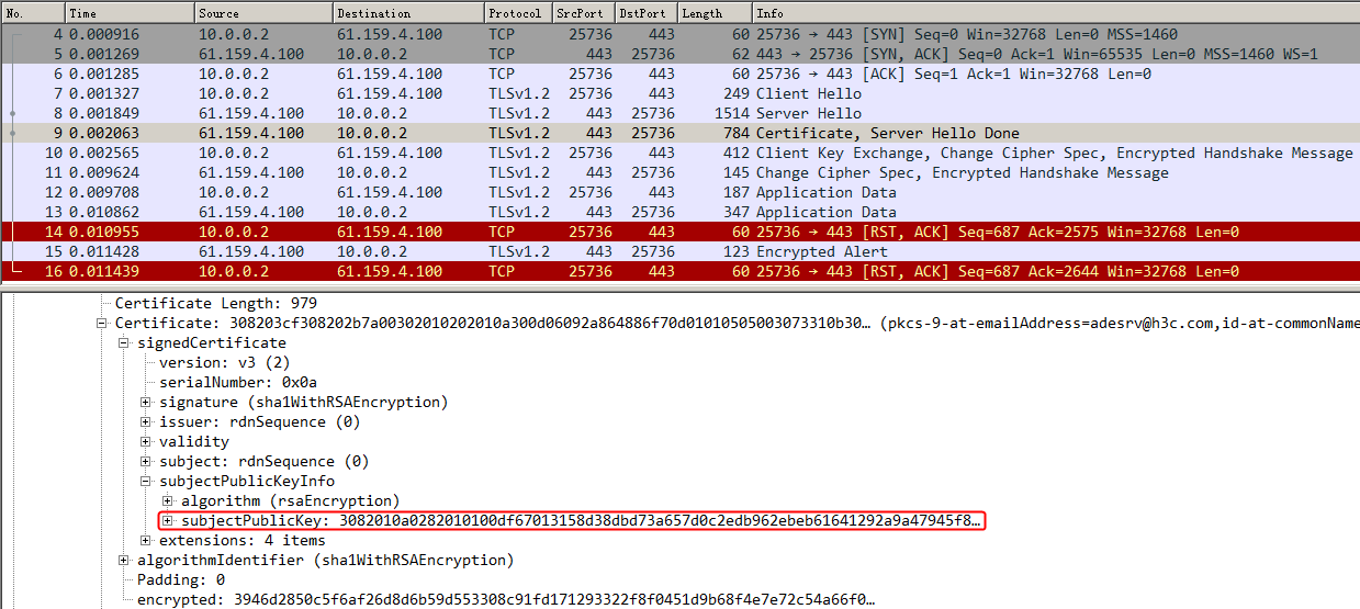
Figure 372 Device public key
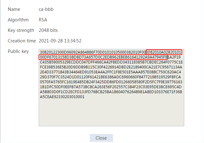
Configuration files
#
nqa template http t1
expect status 200
#
pki domain ca_aaa
public-key rsa general name ca-aaa
undo crl check enable
#
pki domain ca_bbb
public-key rsa general name ca-bbb length 2048
undo crl check enable
#
pki domain ca_default
public-key ecdsa name ca-default secp256r1
undo crl check enable
#
ssl server-policy ssl_aaa
pki-domain ca_aaa
ciphersuite dhe_rsa_aes_256_cbc_sha rsa_aes_256_cbc_sha dhe_rsa_aes_128_cbc_sha rsa_aes_128_cbc_sha rsa_aes_128_cbc_sha256 rsa_aes_
256_cbc_sha256 dhe_rsa_aes_128_cbc_sha256 dhe_rsa_aes_256_cbc_sha256 ecdhe_rsa_aes_128_cbc_sha256 ecdhe_rsa_aes_256_cbc_sha384 ecdhe
_rsa_aes_128_gcm_sha256
ciphersuite ecdhe_rsa_aes_256_gcm_sha384 ecdhe_ecdsa_aes_128_cbc_sha256 ecdhe_ecdsa_aes_256_cbc_sha384 ecdhe_ecdsa_aes_128_gcm_sha2
56 ecdhe_ecdsa_aes_256_gcm_sha384 tls_aes_128_gcm_sha256 tls_aes_256_gcm_sha384 tls_chacha20_poly1305_sha256 tls_aes_128_ccm_sha256
tls_aes_128_ccm_8_sha256
certificate-chain-sending enable
version ssl3.0 disable
version tls1.0 disable
#
ssl server-policy ssl_bbb
pki-domain ca_bbb
ciphersuite dhe_rsa_aes_256_cbc_sha rsa_aes_256_cbc_sha dhe_rsa_aes_128_cbc_sha rsa_aes_128_cbc_sha rsa_aes_128_cbc_sha256 rsa_aes_
256_cbc_sha256 dhe_rsa_aes_128_cbc_sha256 dhe_rsa_aes_256_cbc_sha256 ecdhe_rsa_aes_128_cbc_sha256 ecdhe_rsa_aes_256_cbc_sha384 ecdhe
_rsa_aes_128_gcm_sha256
ciphersuite ecdhe_rsa_aes_256_gcm_sha384 ecdhe_ecdsa_aes_128_cbc_sha256 ecdhe_ecdsa_aes_256_cbc_sha384 ecdhe_ecdsa_aes_128_gcm_sha2
56 ecdhe_ecdsa_aes_256_gcm_sha384 tls_aes_128_gcm_sha256 tls_aes_256_gcm_sha384 tls_chacha20_poly1305_sha256 tls_aes_128_ccm_sha256
tls_aes_128_ccm_8_sha256
certificate-chain-sending enable
version ssl3.0 disable
version tls1.0 disable
#
ssl server-policy ssl_default
pki-domain ca_default
ciphersuite dhe_rsa_aes_256_cbc_sha rsa_aes_256_cbc_sha dhe_rsa_aes_128_cbc_sha rsa_aes_128_cbc_sha rsa_aes_128_cbc_sha256 rsa_aes_
256_cbc_sha256 dhe_rsa_aes_128_cbc_sha256 dhe_rsa_aes_256_cbc_sha256 ecdhe_rsa_aes_128_cbc_sha256 ecdhe_rsa_aes_256_cbc_sha384 ecdhe
_rsa_aes_128_gcm_sha256
ciphersuite ecdhe_rsa_aes_256_gcm_sha384 ecdhe_ecdsa_aes_128_cbc_sha256 ecdhe_ecdsa_aes_256_cbc_sha384 ecdhe_ecdsa_aes_128_gcm_sha2
56 ecdhe_ecdsa_aes_256_gcm_sha384 tls_aes_128_gcm_sha256 tls_aes_256_gcm_sha384 tls_chacha20_poly1305_sha256 tls_aes_128_ccm_sha256
tls_aes_128_ccm_8_sha256
certificate-chain-sending enable
version ssl3.0 disable
version tls1.0 disable
undo version gm-tls1.1 disable
#
server-farm sf1
predictor hash address source
probe t1
success-criteria at-least 1
real-server rs1 port 80
success-criteria at-least 1
real-server rs2 port 80
success-criteria at-least 1
real-server rs3 port 80
success-criteria at-least 1
#
real-server rs1
ip address 192.168.1.1
#
real-server rs2
ip address 192.168.1.2
#
real-server rs3
ip address 192.168.1.3
#
virtual-server vs type http
port 443
virtual ip address 61.159.4.100
default server-farm sf1
ssl-server-policy ssl_default
ssl-server-policy ssl_aaa sni www.aaa.com
ssl-server-policy ssl_bbb sni www.bbb.com
sticky-sync enable global
service enable
#
Example: Configuring connection reuse
Network configuration
The connection reuse feature stores the server connections that are not transmitting data into the cache pool, and reuses the connections for client HTTP requests. This feature ensures server performance and the delay caused by establishing new TCP connections with the server. In addition, it minimizes the number of concurrent connections on the back-end server to save server resources.
The host accesses three servers through the LB device. These three servers Server A, Server B, and Server C can provide HTTP services. The host traffic will be load-shared among these servers. Enable the connection reuse feature to establish a connection that does not age for a long time between the LB device and the server. Multiple clients can reuse the same TCP connection with the server.
Figure 373 Network diagram

Analysis
To configure HTTP connection reuse, complete the following configuration on the LB device:
· Create a parameter profile of HTTP type and enable connection reuse.
· Specify the parameter profile for the HTTP virtual server.
· Reuse a TCP connection when a large number of hosts access the server through multiple connections.
Software versions used
This configuration example was created and verified on Feature 1160P16 of L1070.
Restrictions and guidelines
When you configure HTTP connection reuse, follow these restrictions and guidelines:
· Make sure a route is available from the host to the LB device.
· Configure an SNAT pool for a server farm.
· Specify the real server addresses on the LB device as the actual server addresses.
Procedures
Perform the following configuration on the LB device.
Assigning IP addresses to interfaces
Details not shown.
Creating a health monitoring template
1. Navigate to the LB > Global Configuration > Health Monitoring page.
2. Click Create to create a template named t1, specify the type as HTTP, and set the expected status code to 200.
Figure 374 Creating a health monitoring template

3. Click OK.
Creating parameter profiles
1. Navigate to the LB > Application Load Balancing > Parameter Profiles page.
2. Create a parameter profile named pp1, specify the type as HTTP, and enable connection reuse.
Figure 375 Creating an HTTP parameter profile
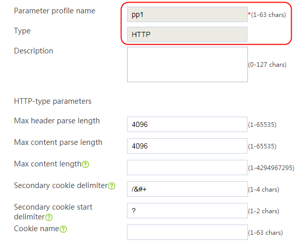
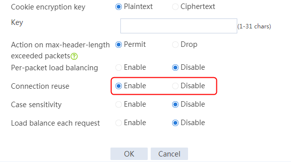
3. Click OK.
4. Create a parameter profile named pp2, specify the type as OneConnect, and specify the idle timeout time as 3 seconds.
Figure 376 Creating a OneConnect parameter profile
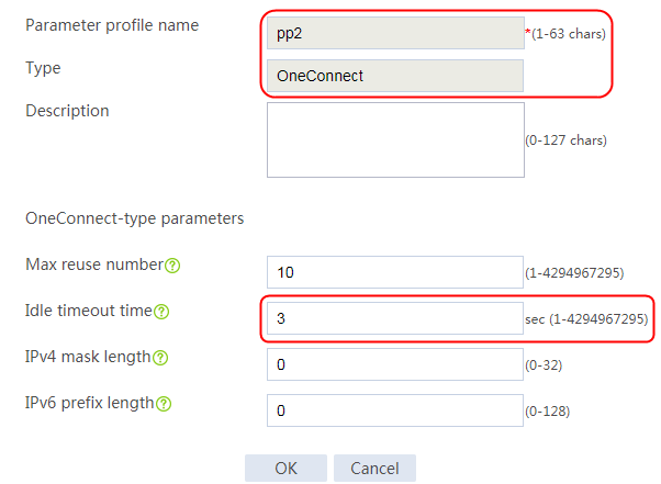
5. Click OK.
Configuring an SNAT pool
1. Navigate to the LB > Public Configuration > SNAT Pool page.
2. Click Create to create an SNAT pool named snat1. Create an address range with start IP address 192.168.1.210 and end IP address 192.168.1.220. Select RAGG1.20 as the interface for sending gratuitous ARP or ND packets.
Figure 377 Creating an SNAT pool
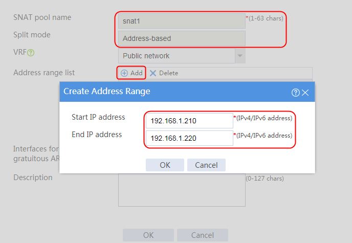
Figure 378 SNAT pool information
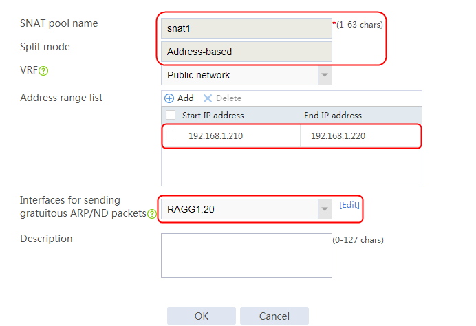
3. Click OK.
Creating a server farm
1. Navigate to the LB > Application Load Balancing > Server Farms page.
2. Create a server farm named sf1. Specify the scheduling algorithm as Round robin, probe method as t1, and SNAT pool as snat1.
Figure 379 Creating a server farm


3. Click OK.
Configuring real servers
1. Navigate to the LB > Application Load Balancing > Server Farms page.
2. Edit server farm sf1, and click Add to create a real server. Specify the real server name as rs1 and IP address as 192.168.1.1.
Figure 380 Adding a real server

Figure 381 Creating a real server

3. Click OK.
4. Create real servers rs2 and rs3 in the same way rs1 is created. Configure the IPv4 addresses for real servers rs2 and rs3 as 192.168.1.2 and 192.168.3, respectively.
Figure 382 Server farm information

Configuring a virtual server
1. Navigate to the LB > Application Load Balancing > Virtual Servers page.
2. Create a virtual server named vs, specify the type as HTTP, configure the virtual server IP as 61.159.4.100 and default server farm as sf1, enable the virtual server feature, and specify parameter profile pp1 of HTTP type and parameter profile pp2 of OneConnect type.
Figure 383 Creating a virtual server


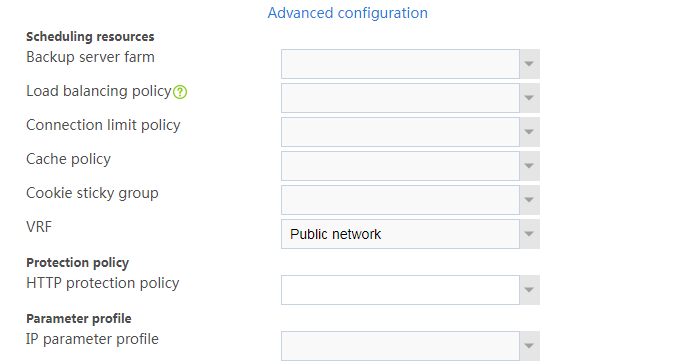
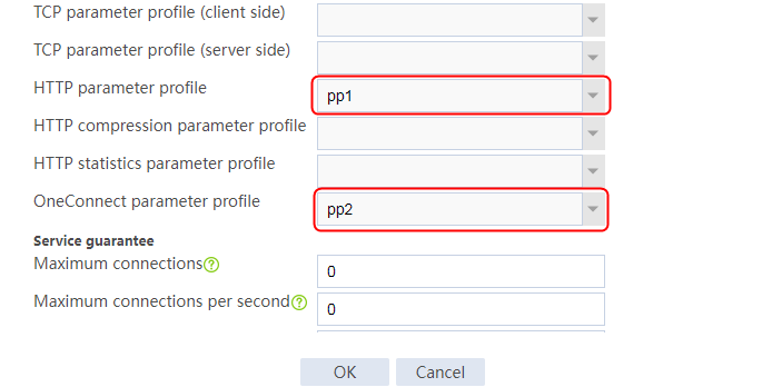
3. Click OK.
Verifying the configuration
Verifying the configuration when connection reuse is disabled
When connection reuse is disabled, a large number of hosts can access the HTTP server through http:// 61.159.4.100 successfully. On the LB device, you can see that the connection establishment rates are equal in the virtual server statistics and real server statistics.
1. Navigate to the Monitor > Application Load Balancing > Virtual Servers > Real-time Statistics page. View the traffic statistics.
Figure 384 Virtual server statistics
![]()
2. Navigate to the Monitor > Application Load Balancing > Real Servers > Real-time Statistics page. View the traffic statistics.
Figure 385 Real server statistics
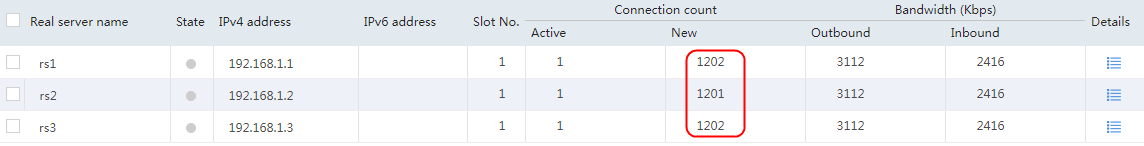
3. Click Details to view the detailed virtual server and real server statistics. You can see that the total number of connections in the virtual server statistics is equal to that in the real server statistics. (Details not shown.)
4. Check the packet captured on the server. One request corresponds to one TCP connection.
Figure 386 Packets captured on the server
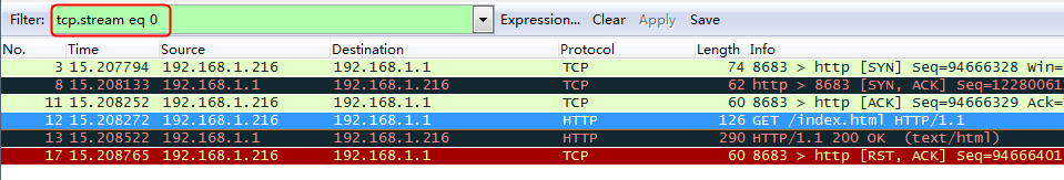
Verifying the configuration when connection reuse is enabled
When connection reuse is enabled, a large number of hosts can access the HTTP server through http:// 61.159.4.100 successfully. On the LB device, you can see that the connection establishment rate in the virtual server statistics is far greater than that in the real server statistics.
1. Navigate to the Monitor > Application Load Balancing > Virtual Servers > Real-time Statistics page. View the traffic statistics.
Figure 387 Virtual server statistics
![]()
2. Navigate to the Monitor > Application Load Balancing > Real Servers > Real-time Statistics page. View the traffic statistics.
Figure 388 Real server statistics
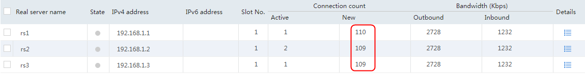
3. Click Detail to view the detailed virtual server and real server statistics. You can see that the total number of connections in the virtual server statistics is far greater than that in the real server statistics. (Details not shown.)
4. Capture packets on the server. You can see that eleven requests share one TCP connection.
Figure 389 Packets captured on the server
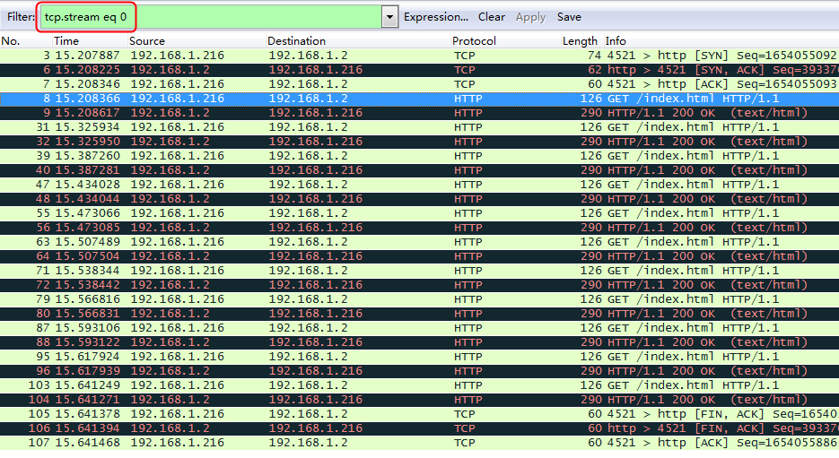
Configuration files
#
nqa template http t1
expect status 200
#
parameter-profile pp1 type http
server-connection reuse
#
parameter-profile pp2 type oneconnect
max-reuse 10
idle-time 3
#
loadbalance snat-pool snat1
ip range start 192.168.1.210 end 192.168.1.220
arp-nd interface Route-Aggregation1.20
#
server-farm sf1
snat-pool snat1
probe t1
success-criteria at-least 1
real-server rs1 port 0
success-criteria at-least 1
real-server rs2 port 0
success-criteria at-least 1
real-server rs3 port 0
success-criteria at-least 1
#
real-server rs1
ip address 192.168.1.1
#
real-server rs2
ip address 192.168.1.2
#
real-server rs3
ip address 192.168.1.3
#
virtual-server vs type http
virtual ip address 61.159.4.100
parameter http pp1
parameter oneconnect pp2
default server-farm sf1
sticky-sync enable global
service enable
#
Example: Configuring HTTP compression
Network configuration
The LB device compresses the response packets from the server, and the host needs to carry Accept-Encoding information. As shown in the Figure 390, the host can access three servers through the LB device. These three servers Server A, Server B, and Server C in the public network can all provide HTTP services. Enable the server to reply with large packets, and configure a parameter profile with compression parameters for the LB device to compress large packets returned from the server to the host.

Analysis
To implement HTTP compression, complete the following configuration on the LB device:
· Configure a parameter profile with compression parameters.
· Configure server farm, real server, and virtual server settings.
· Enable the LB device to compress the large file replied by the server.
Software versions used
This configuration example was created and verified on Feature 1160P16 of L1070.
Procedures
Perform the following configuration on the LB device.
Assigning IP addresses to interfaces
Details not shown.
Creating a health monitoring template
1. Navigate to the LB > Global Configuration > Health Monitoring page.
2. Click Create to create a template named t1, specify the type as HTTP, and set the expected status code to 200.
Figure 391 Creating a health monitoring template

3. Click OK.
Creating a server farm
1. Navigate to the LB > Application Load Balancing > Server Farms page.
2. Click Create to create a server farm named sf1. Specify the scheduling algorithm as Hash source IP address and probe method as t1.
Figure 392 Creating a server farm


3. Click OK.
Configuring real servers
1. Navigate to the LB > Application Load Balancing > Server Farms page.
2. Edit server farm sf1, and click Add to create a real server. Specify the real server name as rs1 and IP address as 192.168.1.1.
Figure 393 Adding a real server

Figure 394 Creating a real server
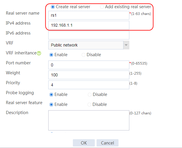
3. Click OK.
4. Create real servers rs2 and rs3 in the same way rs1 is created. Configure the IPv4 addresses for real servers rs2 and rs3 as 192.168.1.2 and 192.168.3, respectively.
Figure 395 Server farm information

Configuring a parameter profile
1. Navigate to the LB > Application Load Balancing > Parameter Profiles page.
2. Click Create to create a parameter profile named pp1. Specify the type as HTTP compression, the compression level as 9, and the preferred compression algorithm as deflate.
Figure 396 Creating parameter profile information
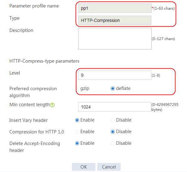
3. Click OK.
Configuring a virtual server
1. Navigate to the LB > Application Load Balancing > Virtual Servers page.
2. Click Create to create a virtual server named vs1, specify the type as HTTP, specify parameter profile pp1, specify server farm sf1, and enable the virtual server feature.
Figure 397 Creating a virtual server


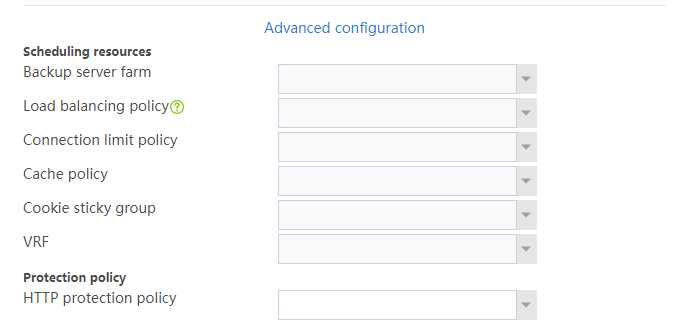
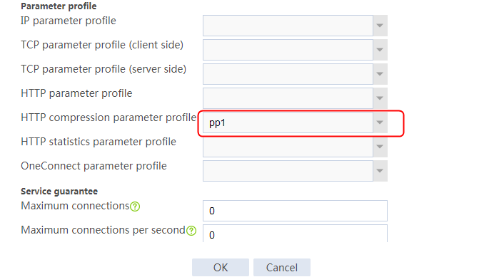
3. Click OK.
Verifying the configuration
The host accesses the server through the browser that supports Accept-Encoding: gzip and deflate by default. Enable the server to reply with a large file of 2512000 bytes. Capture packets on the client. You can see that the compressed length is marked in a red circle for the packet returned by the LB device to the client with a status code of 200 OK.
Figure 398 Packets captured on the host
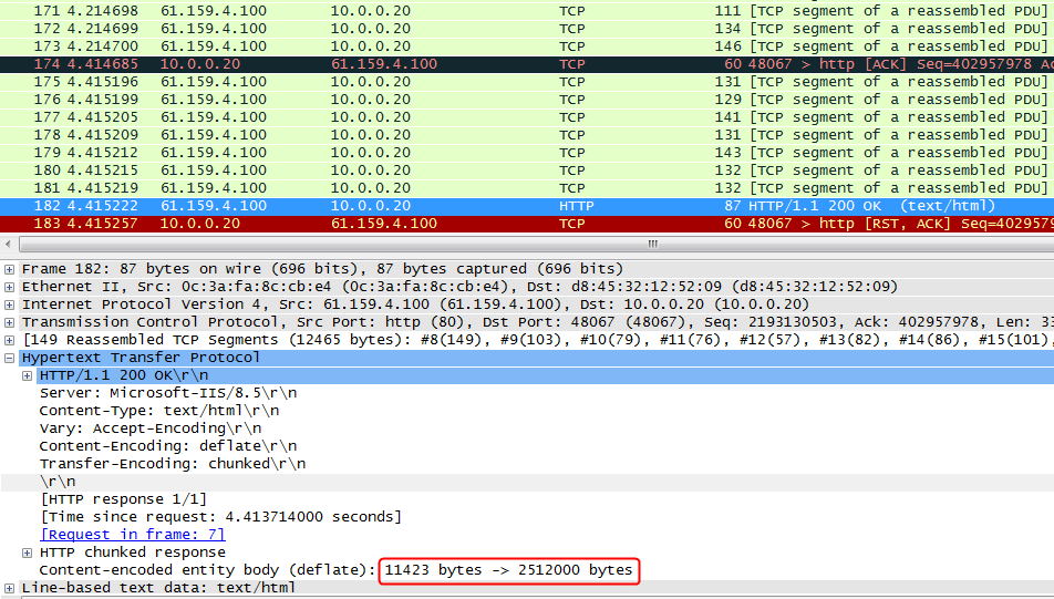
Figure 399 Packets captured on the server
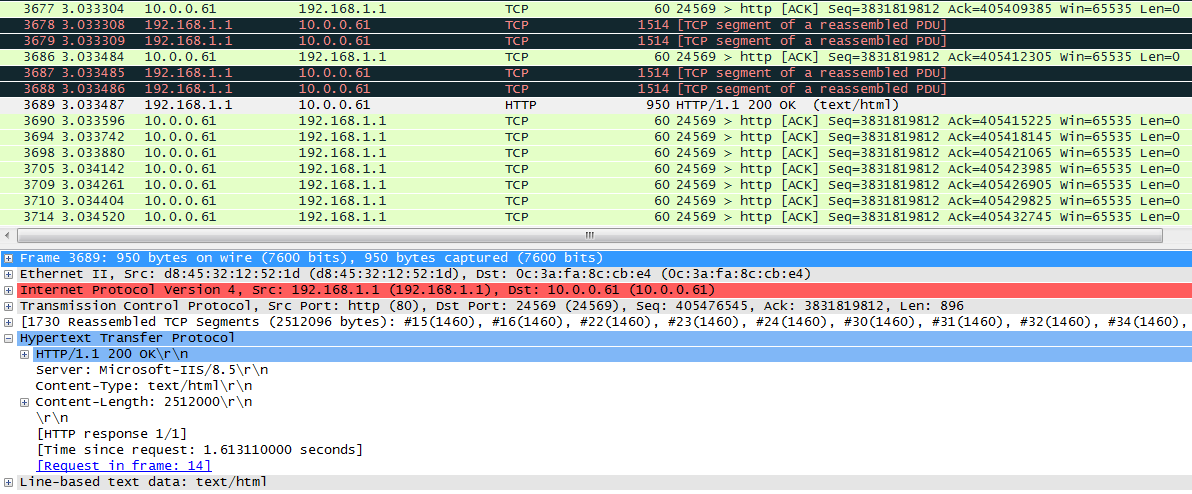
Configuration files
#
nqa template http t1
expect status 200
#
parameter-profile pp1 type http-compression
compression level 9
prefer-method deflate
#
server-farm sf1
predictor hash address source
probe t1
success-criteria at-least 1
real-server rs1 port 0
success-criteria at-least 1
real-server rs2 port 0
success-criteria at-least 1
real-server rs3 port 0
success-criteria at-least 1
#
real-server rs1
ip address 192.168.1.1
#
real-server rs2
ip address 192.168.1.2
#
real-server rs3
ip address 192.168.1.3
#
virtual-server vs1 type http
virtual ip address 61.159.4.100
parameter http-compression pp1
default server-farm sf1
sticky-sync enable global
service enable
#
Example: Configuring a Web cache policy
Network configuration
A Web cache policy allows you to cache frequently accessed webpages locally in files. If a user accesses the same URI before the cached file expires, the device responds with the file instead of sending the request to the server. By using a Web cache policy, you can alleviate the pressure on the server, reduce the transmission costs, and reduce the response time for users.
Other functional modules (for example, an LB virtual server) can use a Web cache policy to cache frequently accessed webpages.
Network caching can address the demands of service quality and high-speed and stable networks.
Deploy a cache device between the server and the client to save the content frequently accessed or downloaded by the user that is larger than 1 KB. When a user accesses or downloads the same content again, the device responds with the content saved in the cache without having to connect to the associated website This can improve the access or download speed and save network bandwidth.
Figure 400 Network diagram

Analysis
To implement the Web cache feature, complete the following configuration on the LB device:
· Configure a Web cache policy.
· Specify the cache policy for the virtual server.
Software versions used
This configuration example was created and verified on Feature 1160P16 of L1070.
Restrictions and guidelines
When you configure a Web cache policy, follow these restrictions and guidelines:
· Configure a Web cache policy.
· The device can cache only the requested files that are larger than 1 KB
Procedures
Assigning IP addresses to interfaces
Details not shown.
Creating a cache policy
1. Navigate to the LB > Application Load Balancing > Advanced Policies > Cache Policy page.
2. Click Create to create a Web cache policy named cache, specify the type as HTTP, and configure relevant parameters as follows.
Figure 401 Creating a Web cache policy
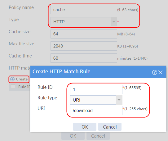
3. Click OK.
Creating a health monitoring template
1. Navigate to the LB > Global Configuration > Health Monitoring page.
2. Click Create to create a template named t1, specify the type as HTTP, and set the expected status code to 200.
Figure 402 Creating a health monitoring template

3. Click OK.
Creating a server farm
1. Navigate to the LB > Application Load Balancing > Server Farms page.
2. Click Create to create a server farm named sf1. Specify the scheduling algorithm as Hash source IP address and probe method as t1.
Figure 403 Creating a server farm


3. Click OK.
Configuring real servers
1. Navigate to the LB > Application Load Balancing > Server Farms page.
2. Edit server farm sf1, and click Add to create a real server. Specify the real server name as rs1 and IP address as 192.168.1.1.
Figure 404 Adding a real server

Figure 405 Creating a real server

3. Click OK.
4. Create real servers rs2 and rs3 in the same way rs1 is created. Configure the IPv4 addresses for real servers rs2 and rs3 as 192.168.1.2 and 192.168.3, respectively.
Figure 406 Server farm information

Creating a virtual server
1. Navigate to the LB > Application Load Balancing > Virtual Servers page.
2. Click Create to create a virtual server named cache, specify the type as HTTP, set the IP address to 61.159.4.100, specify the server farm as sf1, enable the virtual server feature, and specify cache policy cache.
Figure 407 Creating a virtual server

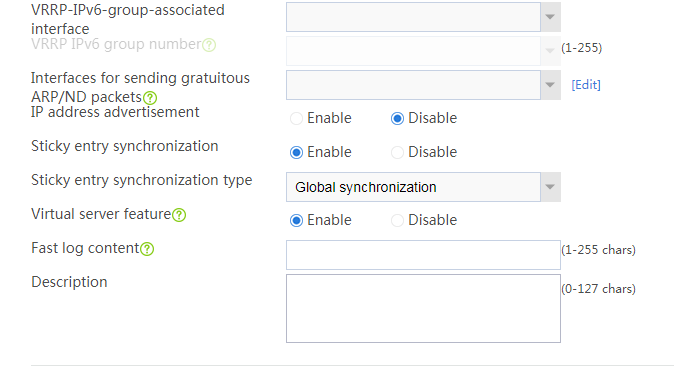
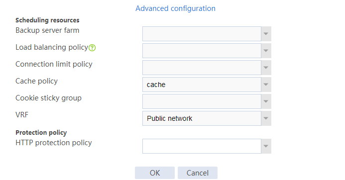
3. Click OK.
Verifying the configuration
Initiating a client request for the first time
1. Initiate a client request with URL http://61.159.4.100/download. The access is successful.
2. Navigate to the Monitor > Application Load Balancing > Virtual Servers > Real-time Statistics page.
Figure 408 Viewing virtual server statistics
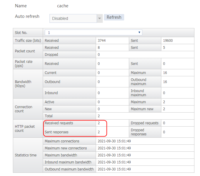
3. Navigate to the Monitor > Application Load Balancing > Real Servers > Real-time Statistics page.
Figure 409 Viewing real server statistics
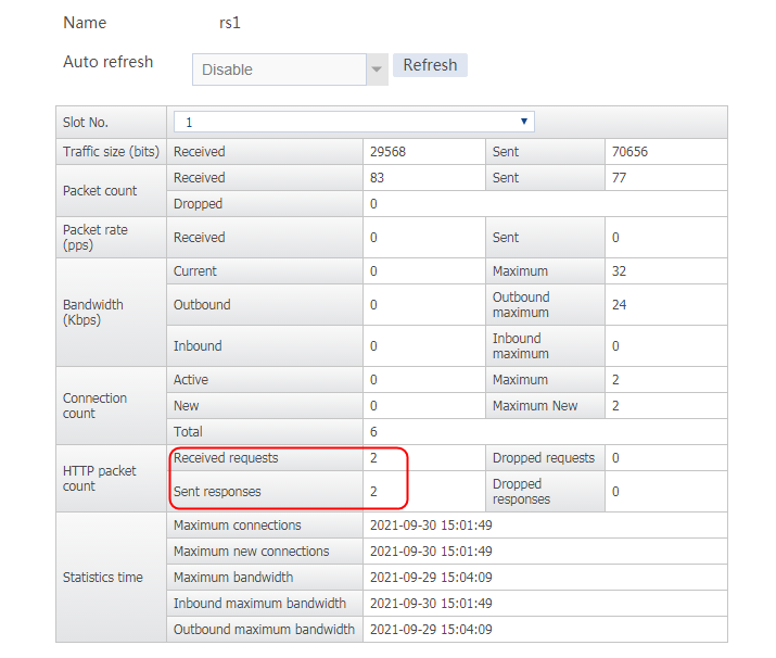
4. Navigate to the LB > Application Load Balancing > Advanced Policies > Cache Policy page. View the number of requests matching the Web cache policy.
Figure 410 Viewing Web cache policy statistics
![]()
Initiate the client request again
1. Initiate the request http://61.159.4.100/download again. The access is successful.
2. Navigate to the Monitor > Application Load Balancing > Virtual Servers > Real-time Statistics page.
Figure 411 Viewing virtual server statistics
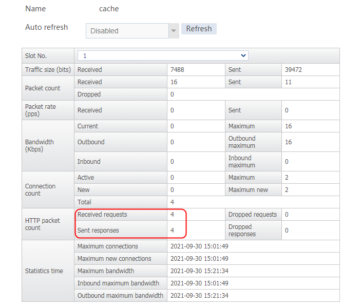
3. Navigate to the Monitor > Application Load Balancing > Real Servers > Real-time Statistics page.
Figure 412 Viewing real server statistics

4. Navigate to the LB > Application Load Balancing > Advanced Policies > Cache Policy page. View the number of requests matching the Web cache policy.
Figure 413 Viewing Web cache policy statistics
![]()
Configuration files
#
nqa template http t1
expect status 200
#
server-farm sf1
predictor hash address source
probe t1
success-criteria at-least 1
real-server rs1 port 0
success-criteria at-least 1
real-server rs2 port 0
success-criteria at-least 1
real-server rs3 port 0
success-criteria at-least 1
#
real-server rs1
ip address 192.168.1.1
#
real-server rs2
ip address 192.168.1.2
#
real-server rs3
ip address 192.168.1.3
#
virtual-server cache type http
virtual ip address 61.159.4.100
default server-farm sf1
sticky-sync enable global
lb-cache-policy cache
service enable
#
cache-policy cache type http
match 1 uri /download
#
Example: Configuring WebSocket
Network configuration
WebSocket is a network technology for full-duplex communication between a client and a server, and is an application layer protocol. It is based on the TCP and uses the handshake channel of HTTP. Specifically, the client negotiates an upgrade protocol with the WebSocket server through an HTTP request. After the protocol upgrade is completed, subsequent data are exchanged based on the WebSocket protocol.
The host can access three servers through the LB device. All the three servers Server A, Server B, and Server C can all provide HTTP services. The host traffic to the server will be load-shared among the three servers.
The client initiates a protocol upgrade request in the standard HTTP packet format, and only supports the GET method. The protocol version is 1.1. The server responds to the protocol upgrade and returns a status code of 101 to indicate protocol switchover.
Figure 414 Network diagram

Analysis
To configure WebSocket, complete the following configuration on the LB device:
· Configure the same basic settings as other Layer 7 load balancing configuration examples.
· This example uses the client-side websocket.html and the server-side server.py application programs to simulate the test. The actual test result might vary by application scenario.
Software versions used
This configuration example was created and verified on Feature 1160P16 of L1070.
Restrictions and guidelines
Make sure the server supports running Python programs and can call the server.py program.
Procedures
Perform the following configuration on the LB device.
Assigning IP addresses to interfaces
Details not shown.
Creating a TCP NQA template
1. Navigate to the LB > Global Configuration > Health Monitoring page.
2. Click Create to create a template named t1, specify the type as HTTP, and set the destination port number to 8000.
Figure 415 Creating a health monitoring template
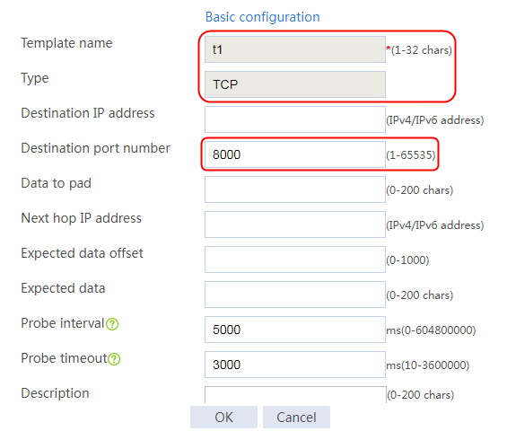
3. Click OK.
Configuring a server farm
1. Navigate to the LB > Application Load Balancing > Server Farms page.
2. Click Create to create a server farm named sf1. Specify the scheduling algorithm as Hash source IP address and probe method as t1.
Figure 416 Creating a server farm


3. Click OK.
Configuring real servers
1. Navigate to the LB > Application Load Balancing > Server Farms page.
2. Edit server farm sf1, and create a real server. Specify the real server name as rs1, IP address as 192.168.1.1, and port number as 8000.
Figure 417 Adding a real server

Figure 418 Creating a real server

3. Click OK.
4. Create real servers rs2 and rs3 in the same way real server rs1 is created. Configure the IPv4 addresses as 192.168.1.2 and 192.168.1.3 and the port number as 8000 for real servers rs2 and rs3, respectively.
Figure 419 Server farm information
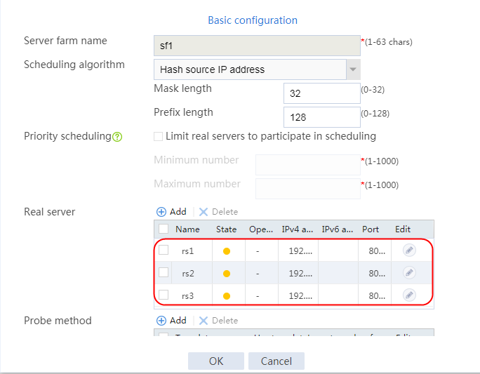
Configuring a virtual server
1. Navigate to the LB > Application Load Balancing > Virtual Servers page.
2. Create a virtual server named vs, specify the type as HTTP, and set the IPv4 address to 61.159.4.100 and the port number to 8000. Specify server farm sf1, and enable the virtual server feature.
3. Click OK.
Figure 420 Creating a virtual server
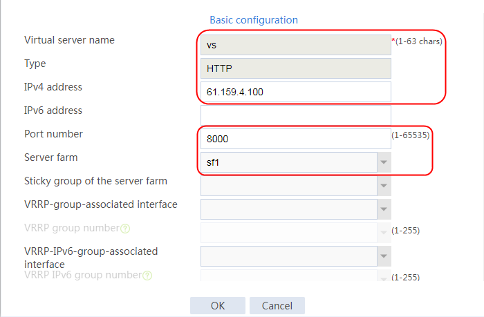
Verifying the configuration
Running the server.py file on the server
Figure 421 Running the server.py file

Opening the websocket.html file on the host
Open the websocket.html file on the host, establish a connection with the virtual service address 61.159.4.100 (port number 8000), and send the WebSocket information. You can see that the connection is established successfully and the information is sent successfully.
Figure 422 Sending the WebSocket information
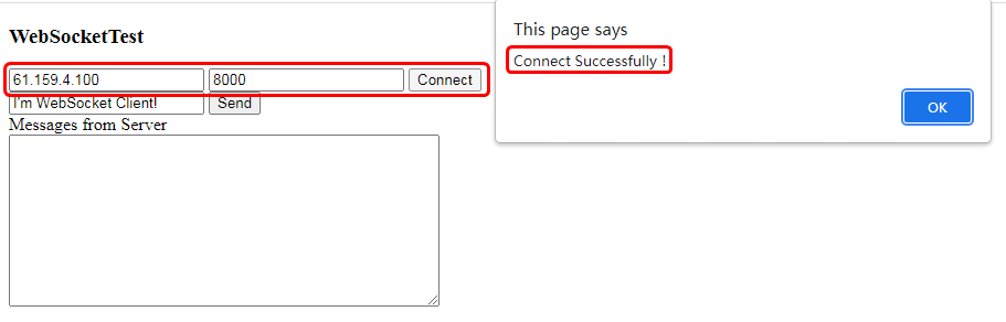
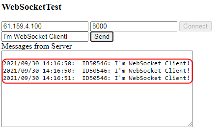
Viewing captured packet information on the host
View captured packet information on the host. You can see that the sent HTTP request packet carries the field Connection: Upgrade.
Figure 423 Packets captured on the host
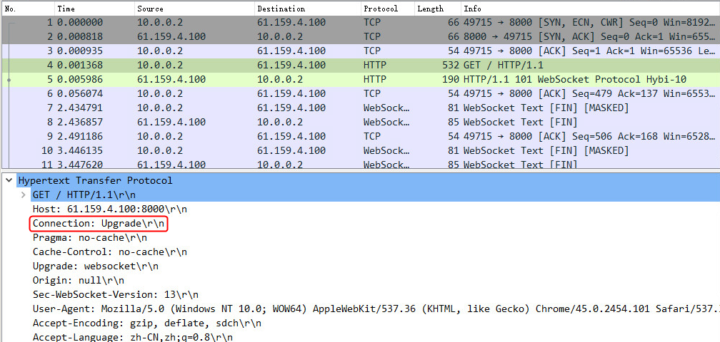
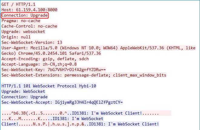
Viewing captured packet information on the server
View captured packet information on the server. You can see that the server responds to the protocol upgrade request, and returns a status code of 101, indicating that the protocol is switched to WebSocket.
Figure 424 Packets captured on the server
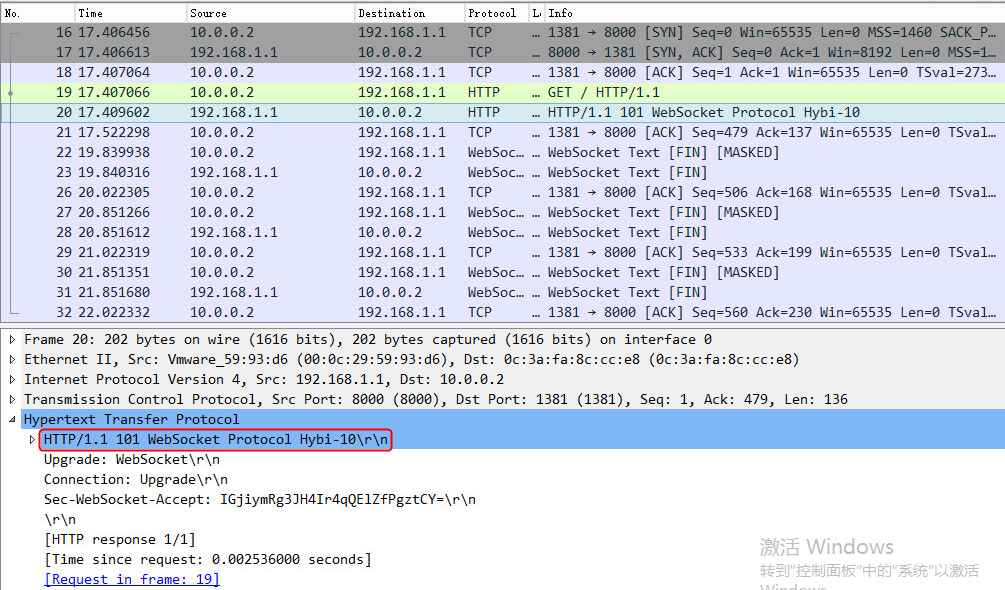
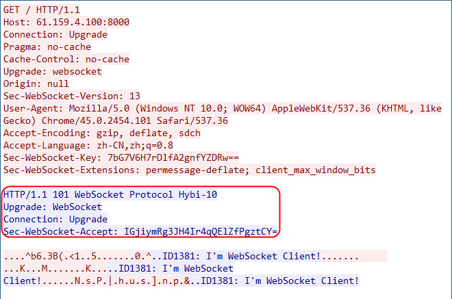
Configuration files
#
nqa template tcp t1
destination port 8000
#
server-farm sf1
predictor hash address source
probe t1
success-criteria at-least 1
real-server rs1 port 8000
success-criteria at-least 1
real-server rs2 port 8000
success-criteria at-least 1
real-server rs3 port 8000
success-criteria at-least 1
#
real-server rs1
ip address 192.168.1.1
#
real-server rs2
ip address 192.168.1.2
#
real-server rs3
ip address 192.168.1.3
#
virtual-server vs type http
port 8000
virtual ip address 61.159.4.100
default server-farm sf1
sticky-sync enable global
service enable
#
Example: Configuring RADIUS load balancing for home broadband AAA authentication
Network configuration
As shown in the Figure 425, the LB device is connected to a cluster of RADIUS servers. The host provides RADIUS services for external users through NAS via the three RADIUS servers. The IP addresses of the RADIUS servers are 192.168.1.1 through 192.168.1.3.
If a user initiates an authentication request to the NAS device, the LB device will distribute the request packets to different RADIUS server for load balancing.
When a small number of NAS devices exist, enable UDP per-packet load balancing to distribute requests to the RADIUS servers more evenly. Configure the RADIUS sticky method distribute authentication packets with the same username to the same authentication server. Configure ICMP and UDP NQA templates for service health check to ensure high availability.
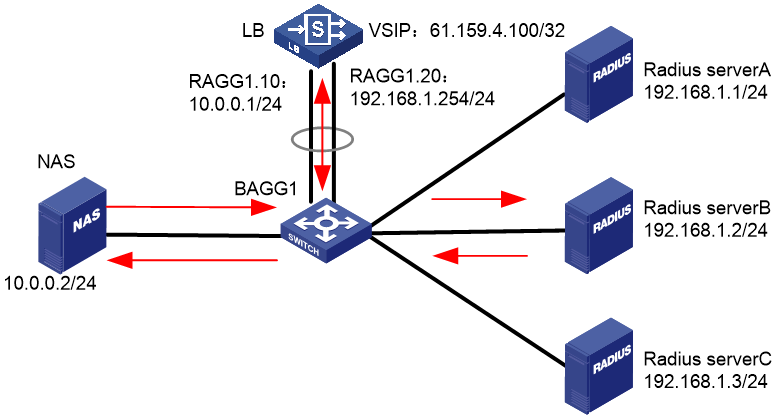
Analysis
To implement RADIUS load sharing for home broadband AAA authentication, complete the following configuration:
· Configure routes between the RADIUS server, NAS client, and LB device.
· Configure UDP per-packet load balancing to load-share services.
· Configure health monitoring of the ICMP type and health monitoring for UDP ports 1812 and 1813 to ensure service reliability.
· Configure a sticky group to distribute authentication packets with the same username to the same authentication server.
Software versions used
This configuration example was created and verified on Alpha 1160P16 of L1000-AK315.
Restrictions and guidelines
In this example, configure the aging timer for RADIUS sticky entries as 3600 seconds. Adjust the value as needed.
Procedures
Perform the following configuration on the LB device.
Assigning IP addresses to interfaces
Details not shown.
Creating health monitoring templates
1. Navigate to the LB > Global Configuration > Health Monitoring page.
2. Click Create to create a template named t1, and specify the type as ICMP.
Figure 426 Creating a health monitoring template
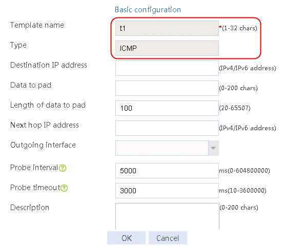
3. Click OK.
4. Create NQA templates t2 and t3, specify the type as UDP, configure the payload fill string, and enable port detection (the settings are not supported on the Web interface in D060SP).
[Sysname]nqa template udp t2
[Sysname-nqatplt-udp-t2]data-fill "default send string" raw
[Sysname-nqatplt-udp-t2]destination port 1812
[Sysname-nqatplt-udp-t2]port-detect enable
[Sysname-nqatplt-udp-t2]reaction trigger probe-pass 1
[Sysname-nqatplt-udp-t2]quit
[Sysname]nqa template udp t3
[Sysname-nqatplt-udp-t3]data-fill "default send string" raw
[Sysname-nqatplt-udp-t3]destination port 1813
[Sysname-nqatplt-udp-t3]port-detect enable
[Sysname-nqatplt-udp-t3]reaction trigger probe-pass 1
Configuring a server farm
1. Navigate to the LB > Application Load Balancing > Server Farms page.
2. Click Create to create a server farm named sf, specify the scheduling algorithm as Round robin, specify the probe templates t1, t2, and t3, and specify the success criteria as All.
Figure 427 Creating a server farm
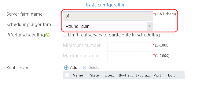
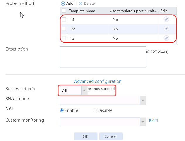
3. Click OK.
Configuring real servers
1. Navigate to the LB > Application Load Balancing > Server Farms page.
2. Edit server farm sf, and add a real server. Specify the real server name as rs1 and IP address as 192.168.1.1.
Figure 428 Adding a real server
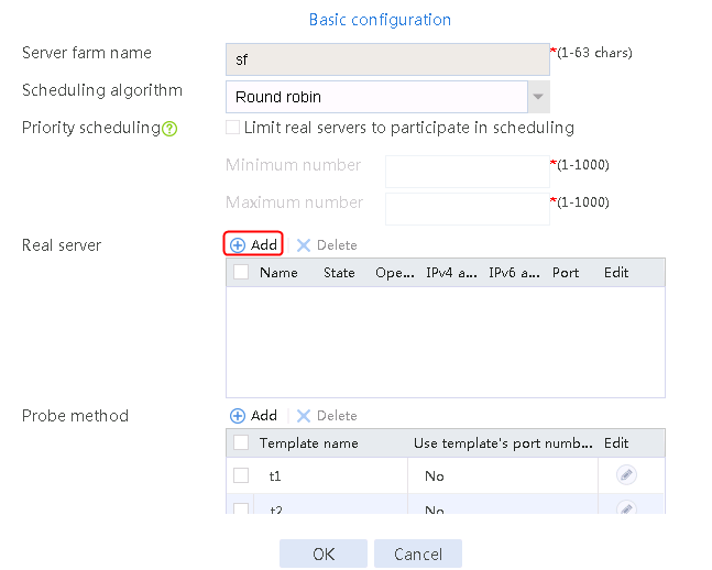
Figure 429 Creating a real server

3. Click OK.
4. Create real servers rs2 and rs3 in the same way real server rs1 is created. Specify the IP address for real servers rs2 and rs3 as 192.168.1.2 and 192.168.1.3, respectively.
Figure 430 Server farm information
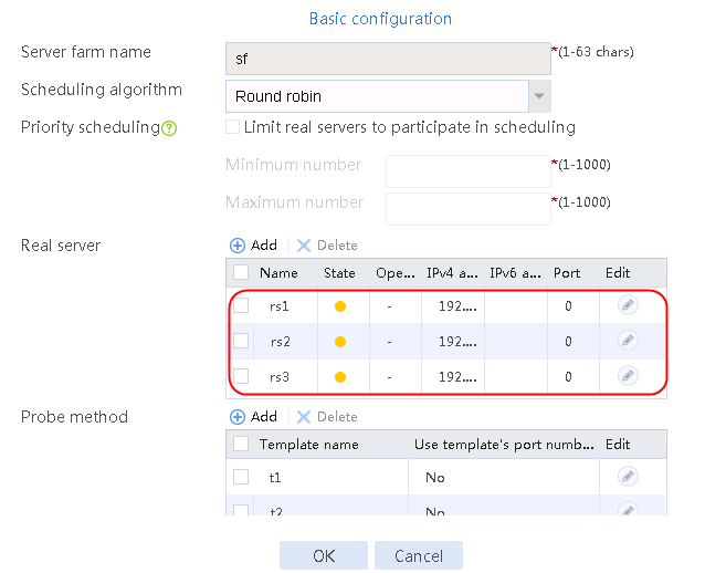
Configuring a sticky group
1. Navigate to the LB > Global Configuration > Sticky Groups page.
2. Click Create to create a sticky group named radius.
3. Set the type to RADIUS, sticky method to user-name, and aging time to 3600s.
Figure 431 Creating a sticky group
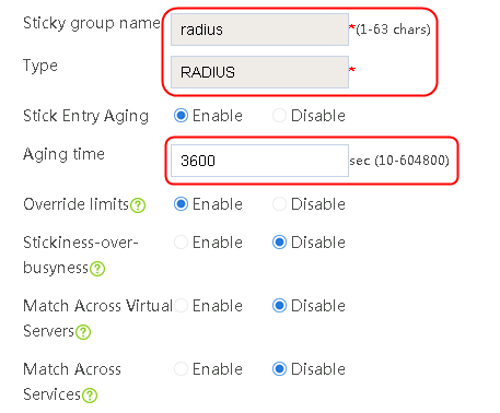
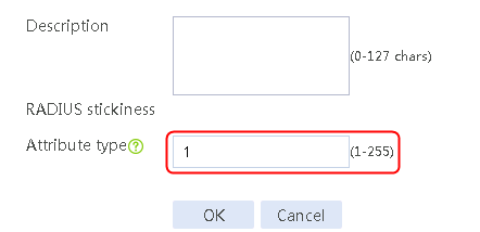
4. Click OK.
Creating a virtual server
1. Navigate to the LB > Application Load Balancing > Virtual Servers page.
2. Click Create to create a virtual server named vs.
3. Specify the type as RADIUS, set the VSIP address to 61.159.4.100, specify server farm sf and sticky group radius, enable UDP per-packet load balancing, and enable the virtual server feature.
Figure 432 Creating a virtual server
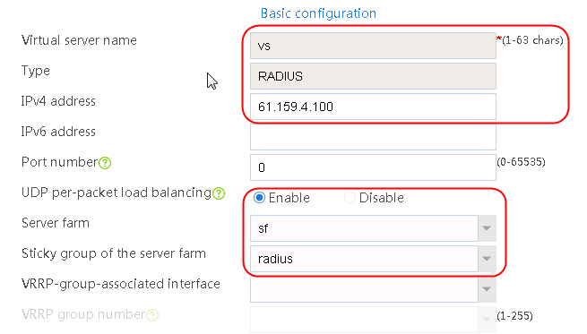

4. Click OK.
Verifying the configuration
The user on the NAS client sends a RADIUS authentication request to the LB device. The LB device load-balances the request among RADIUS servers for processing, and generates sticky entries at the same time.
View the sticky entries, the real server to which the username is assigned:
<Sysname>display sticky virtual-server
Slot 1:
Virtual server name: vs
Server-farm name: sf
Sticky type: RADIUS
Sticky method: Attribute ID
Sticky Key: 8b69353fe93eb925a6b8e98d63a4bd60
Text: admin123
Virtual server addr: 61.159.4.100:1812
Real server addr: 192.168.1.1:0
Client addr: 10.0.0.2
Timeout: 3600 sec
Expiration time: 3512 sec
Initiate RADIUS traffic, and the traffic are load-shared among real servers.
Figure 433 Real server statistics
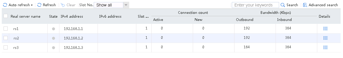
Configuration files
#
nqa template icmp t1
reaction trigger probe-pass 1
#
nqa template udp t2
data-fill "default send string" raw
destination port 1812
port-detect enable
reaction trigger probe-pass 1
#
nqa template udp t3
data-fill "default send string" raw
destination port 1813
port-detect enable
reaction trigger probe-pass 1
#
real-server rs1
ip address 192.168.1.1
success-criteria at-least 1
#
real-server rs2
ip address 192.168.1.2
success-criteria at-least 1
#
real-server rs3
ip address 192.168.1.3
success-criteria at-least 1
#
server-farm sf
probe t2
probe t3
probe t1
real-server rs1 port 0
real-server rs2 port 0
real-server rs3 port 0
#
sticky-group radius type radius
radius-attribute user-name
#
virtual-server vs type radius
virtual ip address 61.159.4.100
default server-farm sf sticky radius
udp per-packet
connection-sync enable
sticky-sync enable
service enable
#
Example: Configuring SIP load balancing
Network configuration
As shown in the Figure 434, the LB device is connected to a cluster of SIP servers that provide SIP services for external users. The IP addresses of the three SIP servers are 192.168.1.1 through 192.168.1.3. The LB device will distribute the SIP request packets sent by the host evenly among the SIP servers. If a small number of SIP clients exist, you can enable traffic to be load-balanced more evenly by distributing SIP requests with the same Call-ID to the same server.
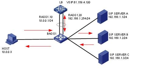
Analysis
To implement SIP load balancing, complete the following configuration on the LB device:
· Configure a SIP sticky group and a SIP health monitoring template.
· Create a server farm, add real servers to it, and specify a SIP health monitoring template.
· Configure a SIP virtual server, and specify a server farm and a SIP sticky group.
Software versions used
This configuration example was created and verified on Feature 1160P16 of L1070.
Restrictions and guidelines
When you configure SIP load balancing, follow these restrictions and guidelines:
· Use a SIP NQA template for health monitoring.
· Enable UDP per-packet load balancing for the SIP-UDP virtual server.
Procedures
Perform the following configuration on the LB device.
Assigning IP addresses to interfaces
Details not shown.
Creating a SIP NQA template
Use the following command to configure a SIP NQA template (not supported on the Web interface):
[Sysname]nqa template sip t1
Configuring a server farm
1. Navigate to the Policies > LB > Server Load Balancing > Server Farm page.
2. Click Create to create a server farm named sf_sip. Specify the scheduling algorithm as Hash source IP address and probe method as sip.
Figure 435 Creating a server farm
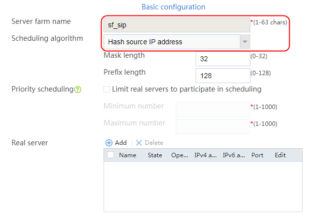
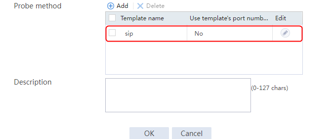
3. Click OK.
Configuring real servers
1. Navigate to the Policies > LB > Server Load Balancing > Server Farm page.
2. Edit server farm sf_sip, and create a real server. Specify the real server name as rs1 and the IP address as 192.168.1.1.
Figure 436 Adding a real server
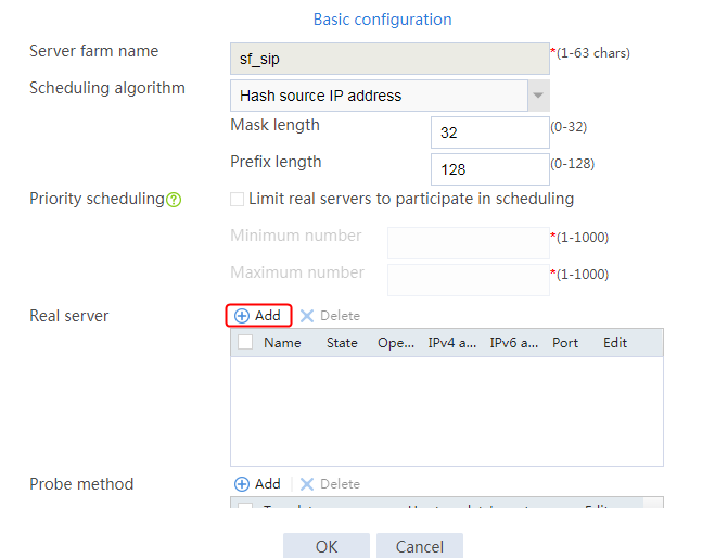
Figure 437 Creating a real server

3. Click OK.
4. Create real servers rs2 and rs3 in the same way real server rs1 is created. Configure the IPv4 addresses as 192.168.1.2 and 192.168.1.3 for real servers rs2 and rs3, respectively.
Figure 438 Server farm information
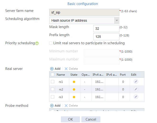
Configuring a sticky group
1. Navigate to the Policies > LB > Public Configuration > Sticky Group page.
2. Click Create to create a sticky group named sip, and specify the type as SIP and the SIP sticky method as Call-ID.
Figure 439 Creating a sticky group sip
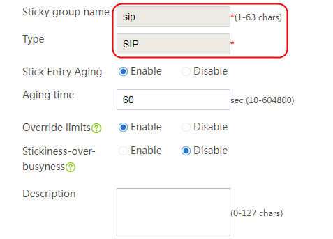

3. Click OK.
Configuring a virtual server
1. Navigate to the Policies > LB > Server Load Balancing > Virtual Servers page.
2. Create a virtual server named vs, specify the type as SIP-UDP, and set the IPv4 address to 61.159.4.100 and the port number to 5060.
3. Enable UDP per-packet load balancing, specify server farm sf_sip and sticky method sip, and enable the virtual server feature.
4. Click OK.
Figure 440 Creating a virtual server
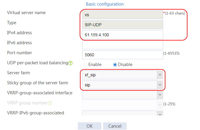
5. Click OK.
Verifying the configuration
Clearing real server statistics
1. Clear real server statistics for accurate verification result, and then inject traffic for verification.
2. Navigate to the Monitor > Application Load Balancing > Real Servers > Real-time Statistics page.
3. Click Clear to clear statistics of all real servers.
Figure 441 Clearing server farm statistics
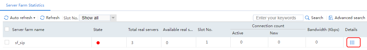
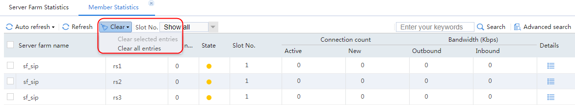
4. Click Details to view the detailed statistics of each real server.
Figure 442 Viewing the detailed statistics of the real server
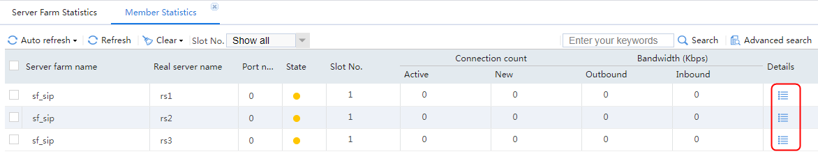
Sending SIP-UDP requests from a large number of users with different Call-IDs to the virtual server
The host initiates SIP-UDP requests to the virtual server with multiple addresses, and the access is successful. The server farm member statistics on the LB device shows that the requests are evenly distributed among the three servers. The packet information shows that the SIP session is successfully established and the RTP media stream is sent.
Figure 443 Statistics result of real server rs1
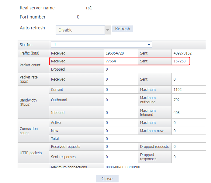
Figure 444 Statistics result of real server rs2

Figure 445 Statistics result of real server rs3

Figure 446 Packet information on the server
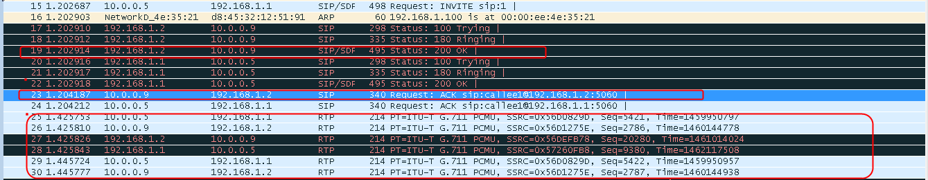
Sending SIP-UDP requests from a small number of users with different Call-IDs to the virtual server
Clear the server farm member statistics. The host initiates SIP-UDP requests to the virtual server with few addresses, and the access is successful. The server farm member statistics on the LB device shows that the requests are evenly distributed among the three servers. The packet information shows that the SIP session is successfully established and the RTP media stream is sent.
Figure 447 Real server statistics
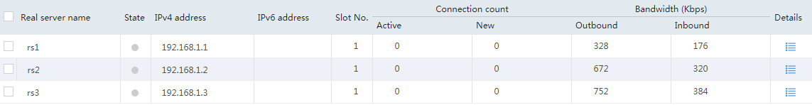
Figure 448 Real server statistics with UDP per-packet load balancing disabled
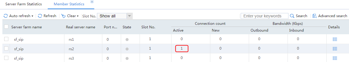
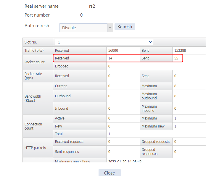
Sending SIP-UDP requests with the same Call-ID to the virtual server
Clear the server farm member statistics. The host initiates SIP-UDP requests with the same Call_ID to the virtual server vs, and the access is successful. The server farm member statistics on the LB device shows that the requests are distributed to one server. The packet information shows that the packets with different source addresses but the same Call-ID are assigned to the same real server.
Figure 449 Virtual server statistics

Figure 450 Real server statistics
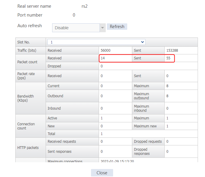
Figure 451 Packets with the same Call-ID assigned to the same server
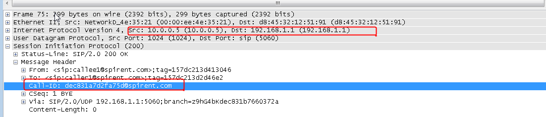
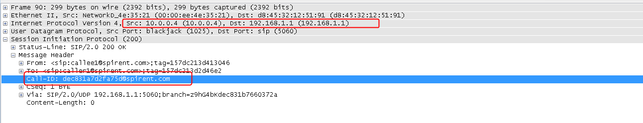
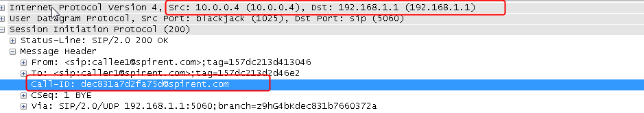
Configuration files
#
server-farm sf_sip
predictor hash address source
probe sip
success-criteria at-least 1
real-server rs1 port 0
success-criteria at-least 1
real-server rs2 port 0
success-criteria at-least 1
real-server rs3 port 0
success-criteria at-least 1
#
nqa template sip sip
#
real-server rs1
ip address 192.168.1.1
success-criteria at-least 1
#
real-server rs2
ip address 192.168.1.2
success-criteria at-least 1
#
real-server rs3
ip address 192.168.1.3
success-criteria at-least 1
#
sticky-group sip type sip
header call-id
#
virtual-server vs type sip-udp
virtual ip address 61.159.4.100
default server-farm sf_sip sticky sip
udp per-packet
connection-sync enable
sticky-sync enable
service enable
#
Example: Configuring MySQL load balancing
Network configuration
For faster MySQL database responses, you can use database load balancing to share user requests among different devices, and reduce the pressure on a single database. In addition, database read requests can be sent to the read server, and database write requests can be sent to the write server.
As shown in the Figure 452, the host can access MySQL servers through the LB device. Server A and Server B process read requests, and Server C processes write requests. Both read and write requests can be distributed to the associated servers without service interruption, and subsequent requests can reuse the previous connections to reduce the pressure on the servers.

Analysis
To implement MySQL load balancing, complete the following configuration on the LB device:
· Configure the read server farm, write server farm, read real server, and write real server settings. Add read and write real servers to the read and write server farms, respectively.
· Configure the virtual server of MySQL type, enable the read/write splitting function, and specify the read and write server farms, respectively. The username and password of the database must be consistent with those in the actual MySQL server. The version number of the database is less than or equal to that of the actual server. As a best practice, use the same version number.
· Configure a parameter profile of the MySQL type, enable connection reuse, and specify it for the MySQL virtual server.
· Configure SNAT settings.
· The read and write requests matching the virtual server will be distributed to the associated real servers in the read and write server farms. Specify the MySQL parameter profile for the virtual server to distribute the read and write requests to the read and write server farms without interrupting server connections.
Software versions used
This configuration example was created and verified on Feature 1160P16 of L1070.
Restrictions and guidelines
When you configure MySQL load balancing, follow these restrictions and guidelines:
· On the MySQL type virtual server, the username and password of the database must be consistent with those in the actual MySQL server. The version number of the database must be less than or equal to that of the real server. As a best practice, use the same version number.
· Enable connection reuse for the MySQL parameter profile, and specify the parameter profile for the MySQL virtual server.
Procedures
Perform the following configuration on the LB device.
Assigning IP addresses to interfaces
Details not shown.
Creating a health monitoring template
1. Navigate to the LB > Global Configuration > Health Monitoring page.
2. Click Create to create a template named t1, specify the type as TCP, and set the destination port number to 3306.
Figure 453 Creating a health monitoring template
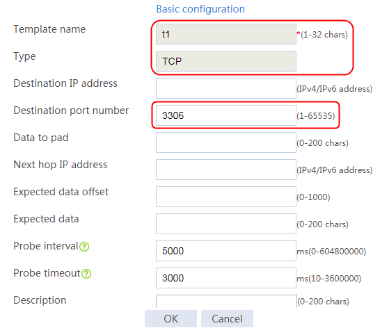
3. Click OK.
Configuring an SNAT pool
1. Navigate to the LB > Public Configuration > SNAT Pool page.
2. Click Create to create an SNAT pool named snat1. Create an address range with start IP address 1.1.1.11 and end IP address1.1.1.20.
Figure 454 Creating an SNAT pool
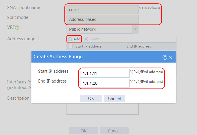
Figure 455 SNAT pool information
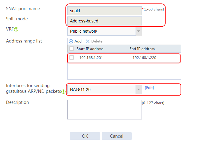
3. Click OK.
Creating server farms
1. Navigate to the LB > Application Load Balancing > Server Farms page.
2. Click Create to create a read server farm named sf_read and write server farm sf_write. Specify the scheduling algorithm as Hash source IP address and probe method as t1.
Figure 456 Creating read server farm sf_read
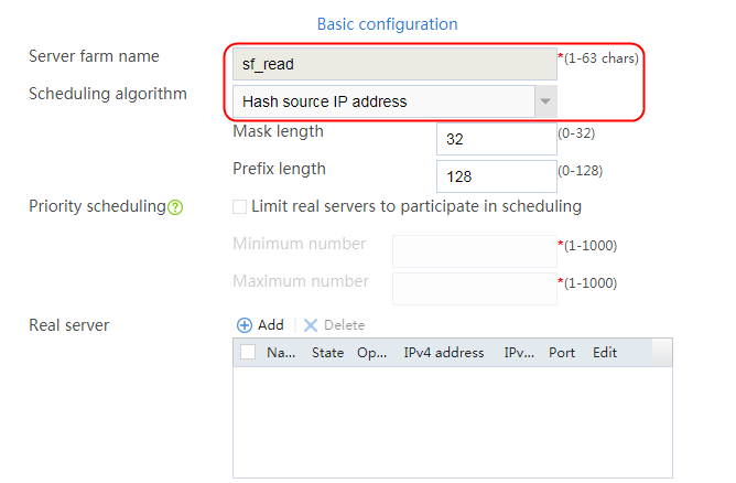

3. Click OK.
Figure 457 Creating write server farm sf_write
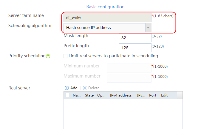

4. Click OK.
Configuring real servers
1. Navigate to the LB > Application Load Balancing > Server Farms page.
2. Edit server farm sf1, and click Add to create a real server. Specify the real server name as rs1 and IP address as 192.168.1.1.
Figure 458 Adding a real server

Figure 459 Creating a real server

3. Click OK.
4. Create real servers rs2 and rs3 in the same way rs1 is created. Configure the IPv4 addresses for real servers rs2 and rs3 as 192.168.1.2 and 192.168.3, respectively.
Figure 460 Server farm information

Adding real servers to server farms
1. Navigate to the LB > Application Load Balancing > Server Farms page.
2. Edit server farm sf_read, and click Add to add a real server. Specify the real server name as rs1 and IP address as 192.168.1.1.
Figure 461 Adding a real server

Figure 462 Creating a real server

3. Click OK.
4. Add real servers rs2 and rs3 in the same way rs1 is added. Add real server rs2 to server farm sf_read, and configure the real server IPv4 address as 192.168.1.2. Add real server rs3 to server farm sf_write, and configure the real server IPv4 address as 192.168.1.3.
Figure 463 Server farm sf_read information
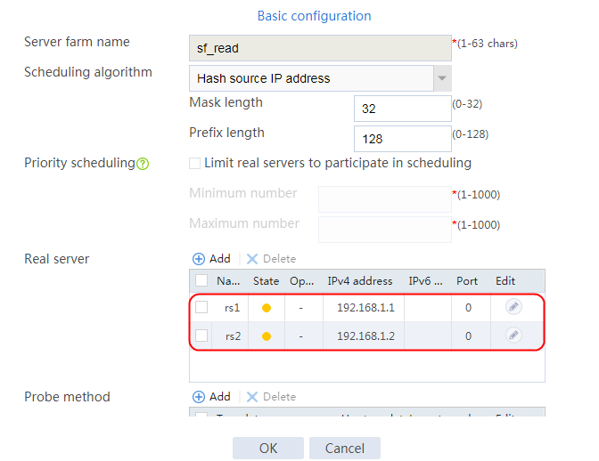
Figure 464 Server farm sf_write information
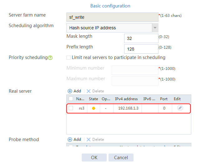
Creating a MySQL parameter profile
1. Navigate to the LB > Application Load Balancing > Parameter Profiles page.
2. Click Create to create a parameter profile named vs, specify the type as MySQL, and enable connection reuse.
Figure 465 Creating a parameter profile
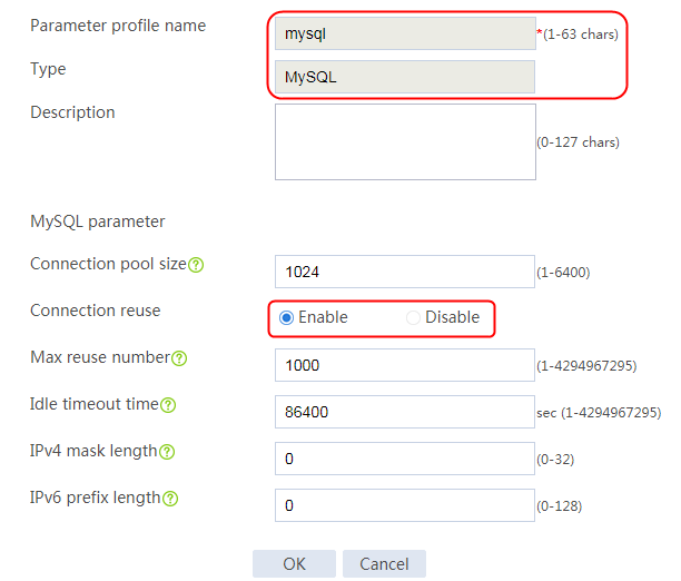
Creating a virtual server
1. Navigate to the LB > Application Load Balancing > Virtual Servers page.
2. Click Create to create a virtual server vs, specify the type as MySQL, set the IP address to 61.159.4.100/32 and the port number to 3306, and enable read/write splitting. Specify read server farm sf_read and write server farm sf_write. Configure the username and password (root/123456) and the version number (5.1) of MySQL, specify MySQL parameter profile mysql, and enable the virtual server feature.
Figure 466 Creating a virtual server
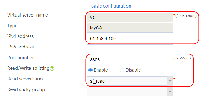
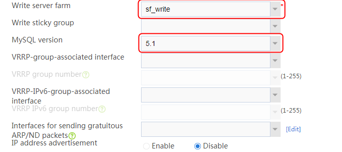
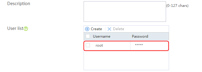
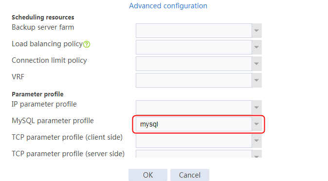
Figure 467 Creating a user
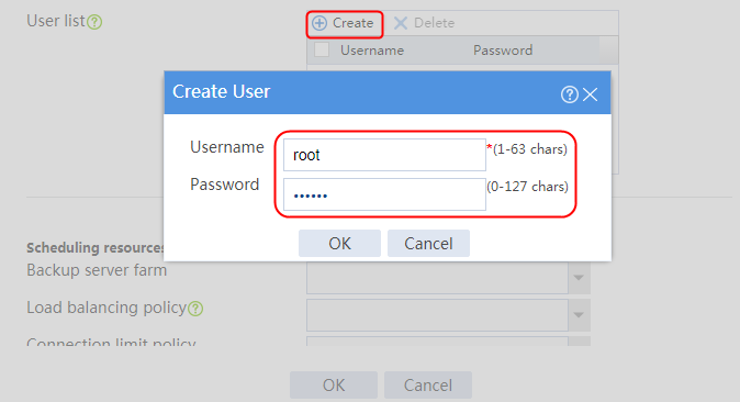
3. Click OK.
Verifying the configuration
The host initiates a MySQL request to the virtual server with IP address 61.159.4.100. After the access is successful, you can view virtual server and real server statistics on the LB device. By capturing packets on the real server, you can see that the source address of the service packets processed by the LB device is an IP address in the SNAT pool, instead of the client address.
Figure 468 Analysis of packets captured on the client
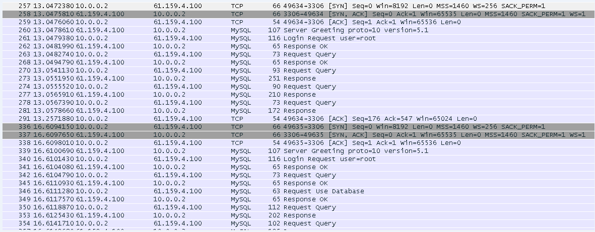
A connection is established for the read and write requests.
Figure 469 Analysis of packets captured on the real server
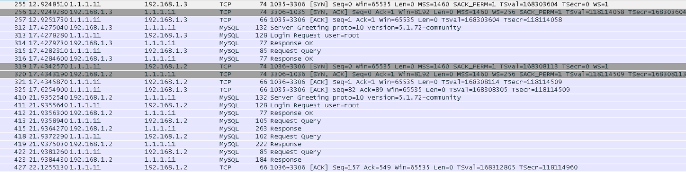
The read request is sent to a read real server, and the write request is sent to a write real server. The existing connection is not interrupted when the read and write requests are sent to the real servers.
Configuration files
#
nqa template tcp t1
destination port 3306
#
parameter-profile mysql type mysql
server-connection reuse
#
loadbalance snat-pool snat1
ip range start 1.1.1.11 end 1.1.1.20
#
server-farm sf_read
predictor hash address source
snat-pool snat1
probe t1
success-criteria at-least 1
real-server rs1 port 0
success-criteria at-least 1
real-server rs2 port 0
success-criteria at-least 1
#
server-farm sf_write
predictor hash address source
snat-pool snat1
probe t1
success-criteria at-least 1
real-server rs3 port 0
success-criteria at-least 1
#
#
real-server rs1
ip address 192.168.1.1
#
real-server rs2
ip address 192.168.1.2
#
real-server rs3
ip address 192.168.1.3
#
virtual-server vs type mysql
virtual ip address 61.159.4.100
parameter mysql mysql
sticky-sync enable global
version 5.1
username root password cipher U1FMAPD7zhCOQGelh2yW3A==
readwrite-separation read-server-farm sf_read write-server-farm sf_write
service enable
#
Example: Configuring load balancing for Oracle database servers
Network configuration
As shown in the Figure 470, the host accesses the Oracle database servers through the LB device. Three servers Server A, Server B and Server C can provide Oracle database services. Configure application load balancing to enable these servers to jointly provide Oracle database services and monitor reachability of the servers through health monitoring.

Analysis
To implement load balancing for Oracle database servers, complete the following configuration on the LB device:
· Configure server farm and real server settings.
· Create a TCP virtual server, and enable the Layer 7 operation mode.
· User requests to the Oracle database that match the virtual server will be load-shared among the real servers through the load balancing method of the server farm. You need to configure the port number monitored by the virtual server as the Oracle server port number.
Software versions used
This configuration example was created and verified on Feature 1160P16 of L1070.
Restrictions and guidelines
When you configure load balancing for Oracle database servers, follow these restrictions and guidelines:
· Configure the port number of the virtual server as the Oracle service port number.
· Enable the Layer 7 operation mode for the TCP virtual server.
Procedures
Perform the following configuration on the LB device.
Assigning IP addresses to interfaces
Details not shown.
Creating a health monitoring template
1. Navigate to the LB > Global Configuration > Health Monitoring page.
2. Click Create to create a template named t1, specify the type as TCP, and set the destination port number to 1521.
Figure 471 Creating a health monitoring template
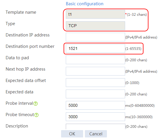
3. Click OK.
Configuring an SNAT pool
1. Navigate to the LB > Public Configuration > SNAT Pool page.
2. Click Create to create an SNAT pool named snat1. Create an address range with start IP address 1.1.1.11 and end IP address 1.1.1.20.
Figure 472 Creating an SNAT pool

Figure 473 SNAT pool information
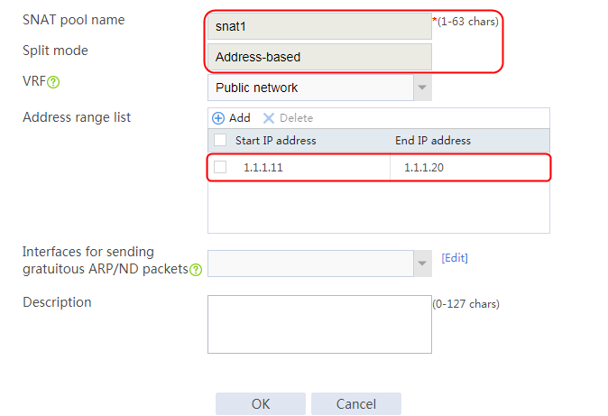
3. Click OK.
Creating a server farm
1. Navigate to the LB > Application Load Balancing > Server Farms page.
2. Create a server farm named sf1. Specify the scheduling algorithm as Round robin, probe method as t1, and SNAT pool as snat1.
Figure 474 Creating a server farm


3. Click OK.
Configuring real servers
1. Navigate to the LB > Application Load Balancing > Server Farms page.
2. Edit server farm sf1, and click Add to create a real server. Specify the real server name as rs1 and IP address as 192.168.1.1.
Figure 475 Adding a real server

Figure 476 Creating a real server

3. Click OK.
4. Create real servers rs2 and rs3 in the same way rs1 is created. Configure the IPv4 addresses for real servers rs2 and rs3 as 192.168.1.2 and 192.168.3, respectively.
Figure 477 Server farm information

Creating a virtual server
1. Navigate to the LB > Application Load Balancing > Virtual Servers page.
2. Click Create to create a virtual server named vs. Specify the type as TCP, IPv4 address as 61.159.4.100/32, and port number as 1521. Enable the Layer 7 operation mode, and enable the virtual server feature.
Figure 478 Creating a virtual server
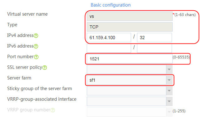
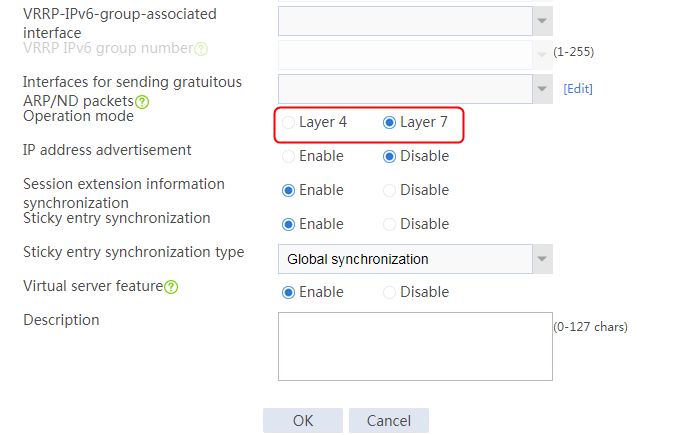
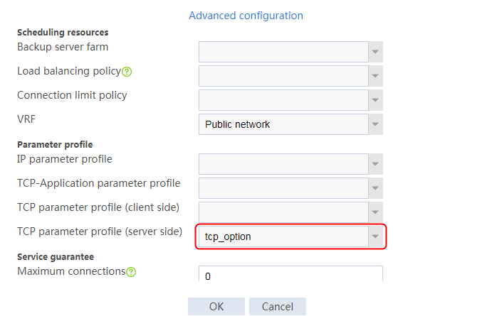
3. Click OK.
Verifying the configuration
The host initiates an Oracle request to the virtual server with IP address 61.159.4.100. After the access is successful, you can view the virtual server and real server statistics on the LB device. By capturing packets on the real server, you can see that the source address of the service packets processed by the LB device is an IP address in the SNAT pool, instead of the client address.
Figure 479 Analysis of packets captured on the client
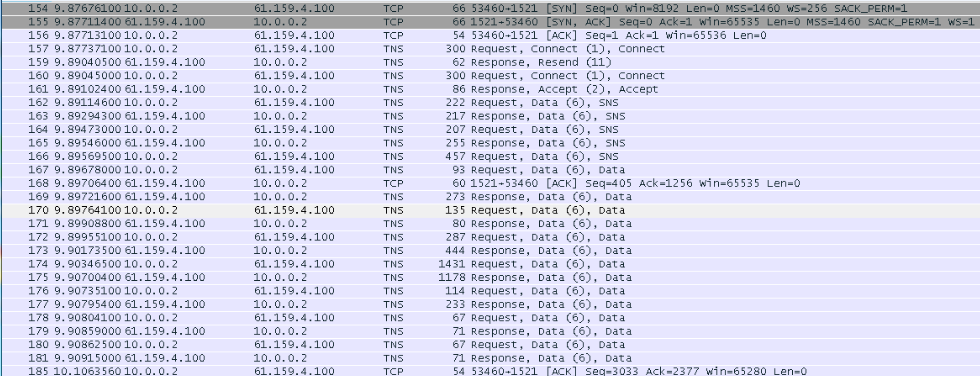
Figure 480 Analysis of packets captured on the real server
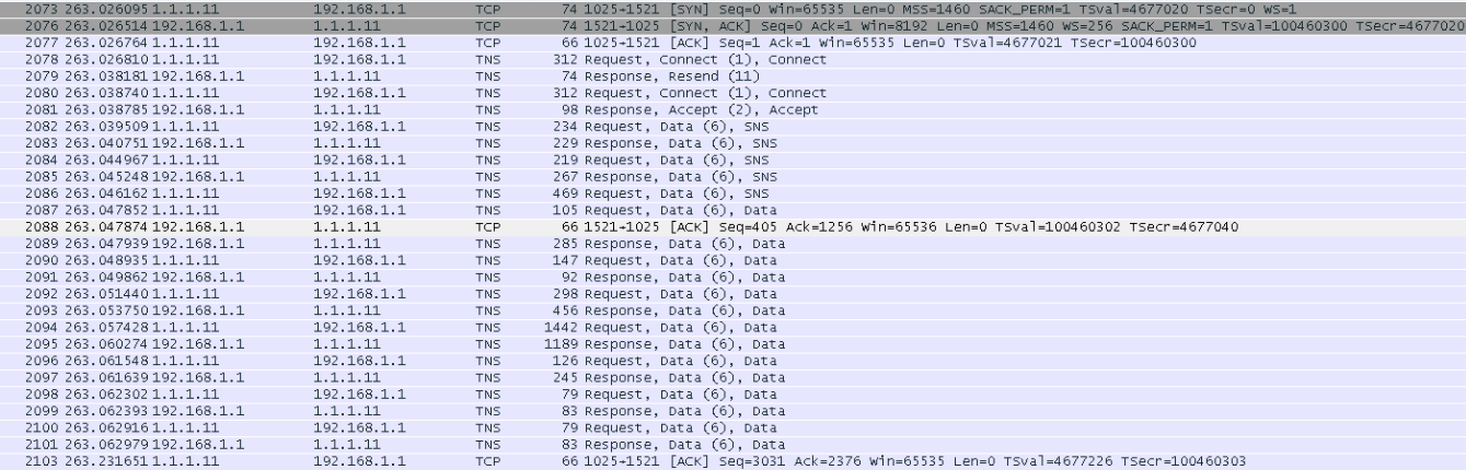
Configuration files
#
nqa template tcp t1
destination port 1521
#
loadbalance snat-pool snat1
ip range start 1.1.1.11 end 1.1.1.20
#
server-farm sf1
predictor hash address source
snat-pool snat1
probe t1
success-criteria at-least 1
real-server rs1 port 0
success-criteria at-least 1
real-server rs2 port 0
success-criteria at-least 1
real-server rs3 port 0
success-criteria at-least 1
#
real-server rs1
ip address 192.168.1.1
#
real-server rs2
ip address 192.168.1.2
#
real-server rs3
ip address 192.168.1.3
#
virtual-server vs type tcp
port 1521
virtual ip address 61.159.4.100
default server-farm sf1
connection-sync enable
sticky-sync enable global
application-mode enable
service enable #
Example: Configuring TCP options
Network configuration
The backend server might fail to obtain the client IP address upon an IP address change, or discard a packet with invalid timestamp. To address the issue, you can insert the client IP address into a TCP option, or remove the specified TCP option (such as timestamp option) from TCP packet headers.
As shown in the Figure 481, the host can access three web servers through the LB device. These three servers Server A, Server B, and Server C in the public network can all provide HTTP services. Configure application load balancing to implement the following requirements:
· Specify an SNAT pool to translate the source address of user request packets.
· Insert the client IP address into TCP Option 28 of TCP packets sent to the server
· Remove TCP Option 8 (timestamp option) from the headers of TCP packets sent by the LB device to the server.

Analysis
To insert client IP address to a TCP option or remove a TCP option, complete the following configuration on the LB device:
· Configure server farm and real server settings.
· Configure an SNAT address pool and specify it for the server farm.
· Configure a TCP parameter profile to insert client IP address to TCP option 28 and remove TCP option 8 (timestamp).
· Configure a TCP virtual server, enable the Layer 7 operation mode, and specify the TCP parameter profile for this virtual server.
· Enable the LB device to translate the source address in the HTTP request packet matching the virtual server into an IP address in the SNAT pool before sending the packet to the server. At the same time, the LB device inserts the client IP address into TCP Option 28 of the TCP packet, and removes TCP Option 8 from the TCP packet.
Software versions used
This configuration example was created and verified on Feature 1160P16 of L1070.
Restrictions and guidelines
When you insert client IP address to a TCP option or remove a TCP option, follow these restrictions and guidelines:
· Specify a non-zero port number for the TCP virtual server, and enable the Layer 7 operation mode.
· Configure a TCP parameter profile to insert client IP address to TCP option 28 and remove TCP option 8 (timestamp).
· The Layer 7 HTTP virtual services are supported at the same time.
Procedures
Perform the following configuration on the LB device.
Assigning IP addresses to interfaces
Details not shown.
Creating a health monitoring template
1. Navigate to the LB > Global Configuration > Health Monitoring page.
2. Click Create to create an NQA template named t1. Specify the template type as TCP and destination port number as 80.
Figure 482 Creating a health monitoring template

3. Click OK.
Configuring an SNAT pool
1. Navigate to the LB > Public Configuration > SNAT Pool page.
2. Click Create to create an SNAT pool named snat1. Create an address range with start IP address 192.168.1.201 and end IP address 192.168.1.210. Select RAGG1.20 as the interface for sending gratuitous ARP or ND packets.
Figure 483 Creating an SNAT pool
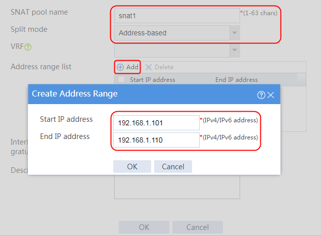
Figure 484 SNAT pool information

3. Click OK.
Creating a server farm
1. Navigate to the LB > Application Load Balancing > Server Farms page.
2. Create a server farm named sf1. Specify the scheduling algorithm as Round robin, probe method as t1, and SNAT pool as snat1.
Figure 485 Creating a server farm


3. Click OK.
Configuring real servers
1. Navigate to the LB > Application Load Balancing > Server Farms page.
2. Edit server farm sf1, and click Add to create a real server. Specify the real server name as rs1 and IP address as 192.168.1.1.
Figure 486 Adding a real server
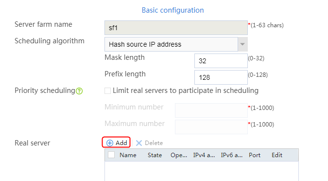
Figure 487 Creating a real server

3. Click OK.
4. Create real servers rs2 and rs3 in the same way rs1 is created. Configure the IPv4 addresses for real servers rs2 and rs3 as 192.168.1.2 and 192.168.3, respectively.
Figure 488 Server farm information

Creating a parameter profile
1. Navigate to the LB > Application Load Balancing > Parameter Profiles page.
2. Click Create to create a parameter profile named tcp_option, and specify the type as TCP.
3. Specify TCP option 28 to insert the client IP address into the TCP option, and specify TCP option 8 (timestamp option) to be removed from TCP packet headers.
Figure 489 Creating a parameter profile
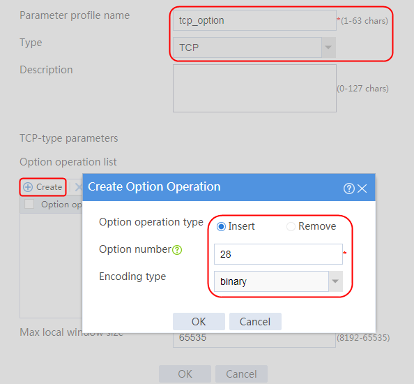
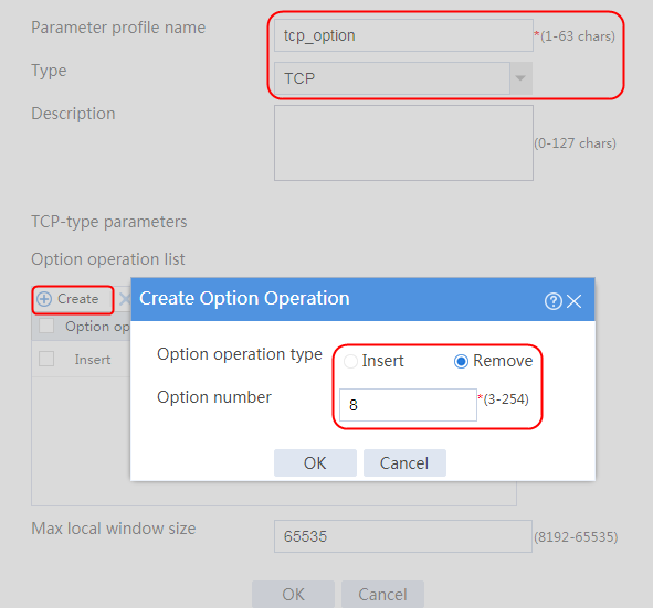
4. Click OK.
Figure 490 Parameter profile information
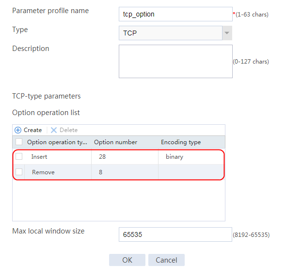
Creating a virtual server
1. Navigate to the LB > Application Load Balancing > Virtual Servers page.
2. Click Create to create a virtual server named vs. Specify the type as TCP, IPv4 address as 61.159.4.100/32, and port number as 80. Enable the Layer 7 operation mode, and enable the virtual server feature.
Figure 491 Creating a virtual server
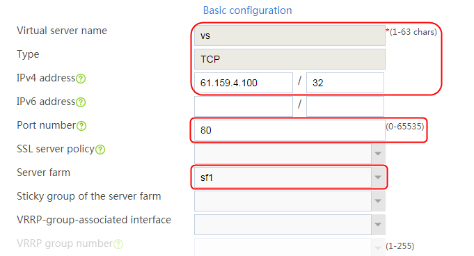


3. Click OK.
Verifying the configuration
Viewing packet information with the parameter profile specified for the virtual server
The host initiates an HTTP request to the virtual server with IP address 61.159.4.100. After the access is successful, view the packets captured on the server.
The client IP address is inserted into TCP Option 28, and TCP Option 8 (timestamp option) is removed from the TCP packet.
Figure 492 TCP packet with client IP address inserted and timestamp option deleted
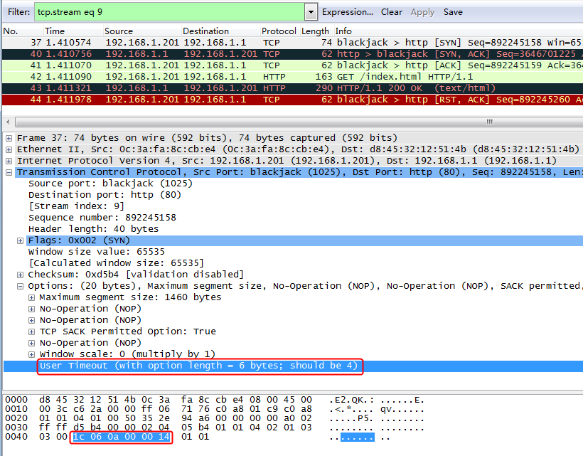
Viewing packet information without specifying a parameter profile for the virtual server
The host initiates an HTTP request to the virtual server with IP address 61.159.4.100. After the access is successful, view the packets captured on the server. You can see that the packet contains a timestamp.
Figure 493 Packets captured on the server when no parameter profile is specified for the virtual server
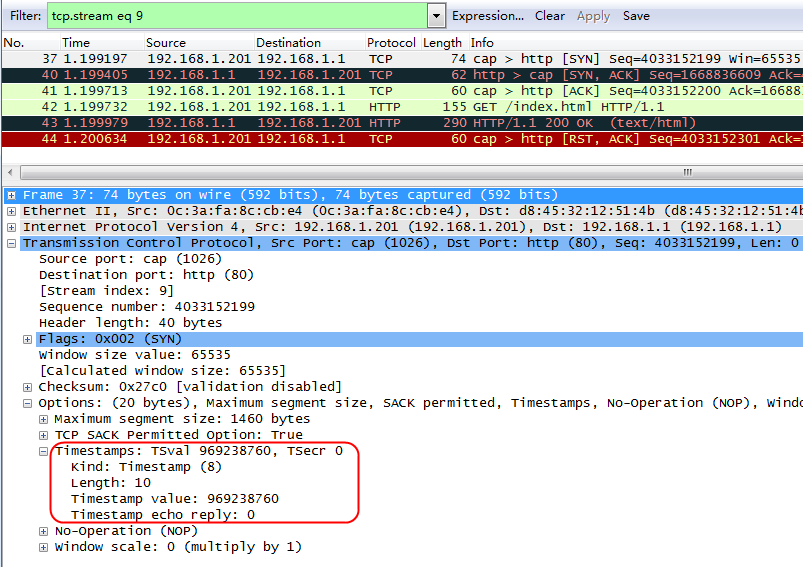
Configuration files
#
nqa template tcp t1
destination port 80
#
parameter-profile tcp_option type tcp
tcp option remove 8
tcp option insert 28 src-addr
#
loadbalance snat-pool snat1
ip range start 192.168.1.201 end 192.168.1.210
arp-nd interface Route-Aggregation1.20
#
server-farm sf1
predictor hash address source
snat-pool snat1
probe t1
success-criteria at-least 1
real-server rs1 port 0
success-criteria at-least 1
real-server rs2 port 0
success-criteria at-least 1
real-server rs3 port 0
success-criteria at-least 1
#
real-server rs1
ip address 192.168.1.1
#
real-server rs2
ip address 192.168.1.2
#
real-server rs3
ip address 192.168.1.3
#
virtual-server vs type tcp
port 80
virtual ip address 61.159.4.100
parameter tcp tcp_option client-side
parameter tcp tcp_option server-side
default server-farm sf1
connection-sync enable
sticky-sync enable global
application-mode enable
service enable
#
NAT64 load balancing configuration examples
Example: Configuring NAT64 load balancing (Layer 7)
Network configuration
As shown in the Figure 494, configure IPv4 and IPv6 SNAT address pools on the LB device to implement the following requirements:
· The host with an IPv4 address can initiate a request destined to the virtual server IPv4 address to access the server with an IPv6 address. In addition, you can view the NAT46 session log on the LB device.
· The host with an IPv6 address can initiate a request destined to the virtual server IPv6 address to access the server with an IPv4 address. In addition, you can view the NAT64 session log on the LB device.
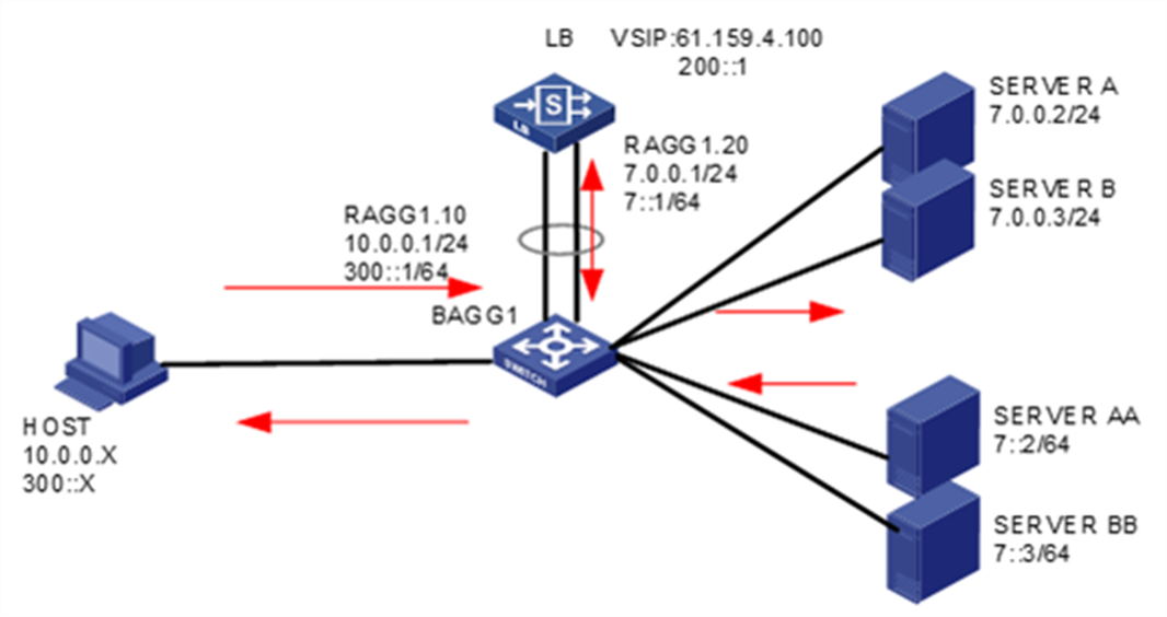
Analysis
To implement Layer 7 NAT64 load balancing, complete the following configuration on the LB device:
· Configure the SNAT address pools to implement NAT64 and NAT46, respectively.
· Enable LB NAT logging for the LB device.
Software versions used
This configuration example was created and verified on Feature 1160P16 of L1070.
Restrictions and guidelines
When you configure Layer 7 NAT64 load balancing, follow these restrictions and guidelines:
· Associate the SNAT address pools with the IPv4 and IPv6 virtual servers, respectively.
· NAT64 supports only the virtual services of HTTP type.
· You need to use relevant commands to configure LB NAT logging that is not supported on the Web interface.
Procedures
Assigning IP addresses to interfaces
Details not shown.
Creating a health monitoring template
1. Navigate to the LB > Global Configuration > Health Monitoring page.
2. Click Create to create a template named t1 and specify the type as HTTP.
Figure 495 Creating a health monitoring template
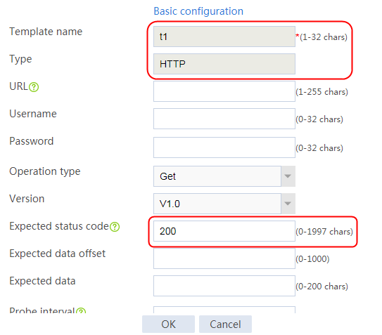
3. Click OK.
Configuring SNAT address pools
1. Navigate to the LB > Global Configuration > SNAT Pool page.
2. Click Create to create an IPv4 SNAT pool named snat1.
Figure 496 Creating an IPv4 SNAT address pool
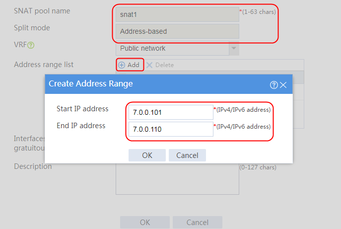

3. Click OK.
4. Create IPv6 address pool snat2 in the same way snat1 is created.
Figure 497 Creating an IPv6 SNAT address pool


Creating server farms
1. Navigate to the LB > Application Load Balancing > Server Farms page.
2. Click Create to create server farms named sf1 and sf2. Specify SNAT address pools snat1 and snat2 for server farms sf1 and sf2, respectively. Specify the scheduling algorithm as Hash source IP address and probe method as t1.
Figure 498 Creating a server farm


3. Click OK.
Figure 499 Creating server farm sf2

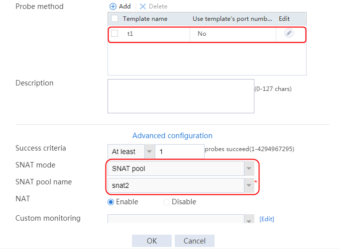
4. Click OK.
Configuring the real server
1. Navigate to the LB > Application Load Balancing > Server Farms page.
2. Edit server farm sf1, and click Add to create a real server. Specify the real server name as rs1 and IP address as 7.0.0.2.
Figure 500 Adding an IPv4 real server

Figure 501 Creating a real server

3. Click OK.
4. Create real server rs2 in the same way real server rs1 is created. Configure the IPv4 address for real server rs2 as 7.0.0.3.
Figure 502 Server farm information

5. Click OK.
6. Navigate to the LB > Application Load Balancing > Server Farms page.
7. Edit server farm sf2, and click Add to create a real server. Specify the real server name as rs11 and the IPv6 address as 7::2.
Figure 503 Adding an IPv6 real server
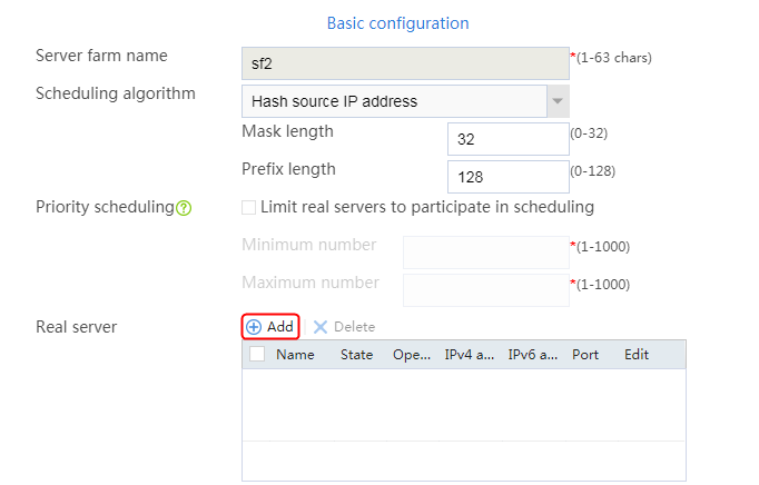
Figure 504 Creating a real server

8. Click OK.
9. Create real server rs12 in the same way rs11 is created. Configure the IPv6 address for real server rs12 as 7::3.
Figure 505 Server farm information

10. Click OK.
Configuring virtual servers
1. Navigate to the LB > Application Load Balancing > Virtual Servers page.
2. Click Create to create virtual servers named vs1 and vs2, specify their IP addresses as 200::1 and 61.159.4.100, and specify server farms sf1 and sf2 for them, respectively. Specify the type as HTTP, and enable the virtual server feature.
Figure 506 Creating virtual server vs1
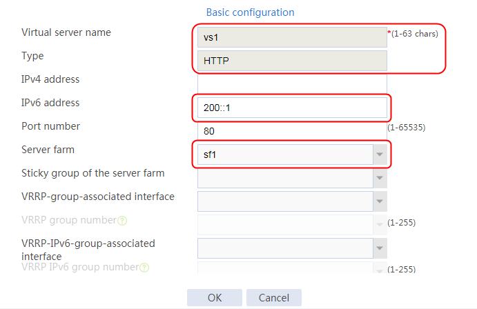
3. Click OK.
Figure 507 Creating virtual server vs1
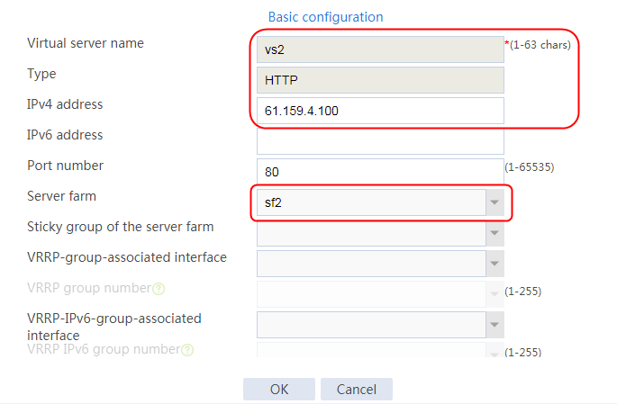
4. Click OK.
Enabling LB NAT logging
Execute the following commands to enable LB NAT logging for the LB device (the configuration is not supported on the Web interface):
[Sysname] loadbalance log enable nat
[Sysname] userlog flow syslog
Verifying the configuration
Accessing an IPv4 server from an IPv6 address
The host with an IPv6 address can successfully access the IPv4 HTTP server through http://200::1.
To view virtual server and real server statistics, NAT64 logs, and session information:
1. Navigate to the Monitor > Application Load Balancing page to view virtual server and real server statistics on the LB device. (Details not shown.)
2. Navigate to the Monitor > Device Logs > System Logs page to view NAT64 logs.
Figure 508 NAT64 logs
![]()
3. Navigate to the Monitor > Sessions Monitoring > Proxy Session page to view proxy session information.
Figure 509 Proxy session information
![]()
Accessing an IPv6 server from an IPv4 address
The host with an IPv4 address can successfully access the IPv6 HTTP server through http://61.159.4.100.
To view virtual server and real server statistics, NAT64 logs, and session information:
1. Navigate to the Monitor > Application Load Balancing page to view virtual server and real server statistics on the LB device. (Details not shown.)
2. Navigate to the Monitor > Device Logs > System Logs page to view NAT64 logs.
Figure 510 NAT64 logs
![]()
3. Navigate to the Monitor > Sessions Monitoring > Proxy Session page to view proxy session information.
Figure 511 Proxy session information
![]()
Configuration files
#
nqa template http t1
expect status 200
#
loadbalance snat-pool snat1
ip range start 7.0.0.101 end 7.0.0.110
arp-nd interface Route-Aggregation1.20
#
loadbalance snat-pool snat2
ipv6 range start 7::101 end 7::10A
arp-nd interface Route-Aggregation1.20
#
server-farm sf1
snat-pool snat1
probe t1
success-criteria at-least 1
real-server rs1 port 0
success-criteria at-least 1
real-server rs2 port 0
success-criteria at-least 1
#
server-farm sf2
predictor hash address source
snat-pool snat2
probe t1
success-criteria at-least 1
real-server rs11 port 0
success-criteria at-least 1
real-server rs12 port 0
success-criteria at-least 1
#
real-server rs1
ip address 7.0.0.2
#
real-server rs11
ipv6 address 7::2
#
real-server rs12
ipv6 address 7::3
#
real-server rs2
ip address 7.0.0.3
#
virtual-server vs1 type http
virtual ipv6 address 200::1
default server-farm sf1
sticky-sync enable global
service enable
#
virtual-server vs2 type http
virtual ip address 61.159.4.100
default server-farm sf2
sticky-sync enable global
service enable
#
loadbalance log enable nat
#
userlog flow syslog
#
Example: Configuring NAT64 load balancing (Layer 4-to-Layer 7)
Network configuration
As shown in Figure 512, enable the LB device to distribute requests from IPv4 address 10.0.0.2 to the HTTP servers with IPv6 addresses 7::2 and 7::3, and distribute requests from IPv6 address 300::2 to the HTTP servers with IPv4 addresses 7.0.0.2 and 7.0.0.3.

Analysis
To implement Layer 4-to-Layer 7 NAT64 load balancing, enable the Layer 7 operation mode for TCP virtual servers on the LB device.
Software versions used
This configuration example was created and verified on Feature 1160P16 of L1070.
Restrictions and guidelines
When you configure Layer 4-to-Layer 7 NAT64 load balancing, follow these restrictions and guidelines:
· Specify SNAT pools for server farms.
· Enable the Layer 7 operation mode for the TCP virtual servers.
· Specify a non-zero port number for the TCP virtual servers.
· This configuration example does not apply to multi-channel protocols, such as FTP.
Procedures
Assigning IP addresses to interfaces
Details not shown.
Creating a health monitoring template
1. Navigate to the LB > Global Configuration > Health Monitoring page.
2. Click Create to create an NQA template named t1. Specify the template type as TCP and destination port number as 80.
Figure 513 Creating a health monitoring template
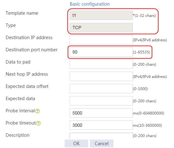
3. Click OK.
Configuring SNAT pools
1. Navigate to the LB > Global Configuration > SNAT Pool page.
2. Click Create to create an SNAT pool named snat1.
Figure 514 Creating an IPv4 SNAT pool


3. Click OK.
4. Create SNAT pool snat2 in the same way snat1 is created.
Figure 515 Creating an IPv6 SNAT pool
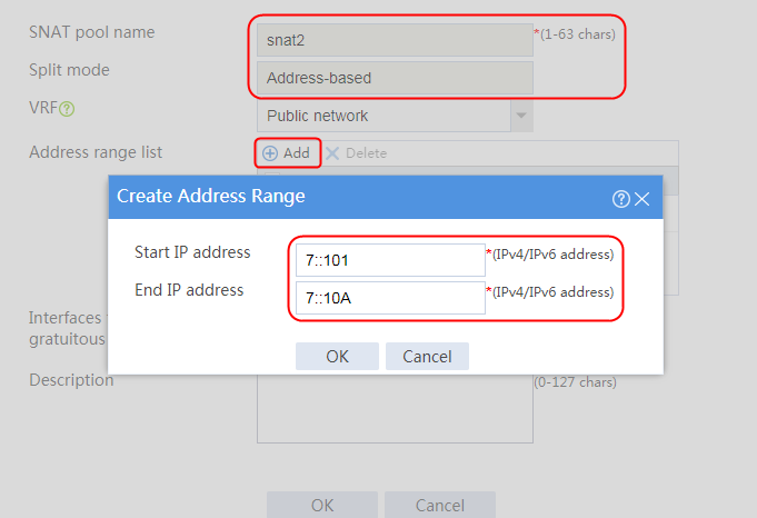
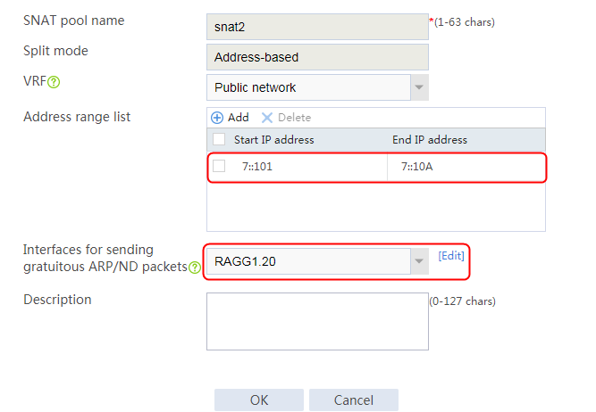
Creating server farms
1. Navigate to the LB > Application Load Balancing > Server Farms page.
2. Click Create to create server farms named sf1 and sf2. Specify SNAT pools snat1 and snat2 for server farms sf1 and sf2, respectively. Specify the scheduling algorithm as Hash source IP address and probe method as t1.
Figure 516 Creating a server farm
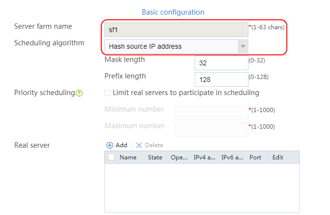
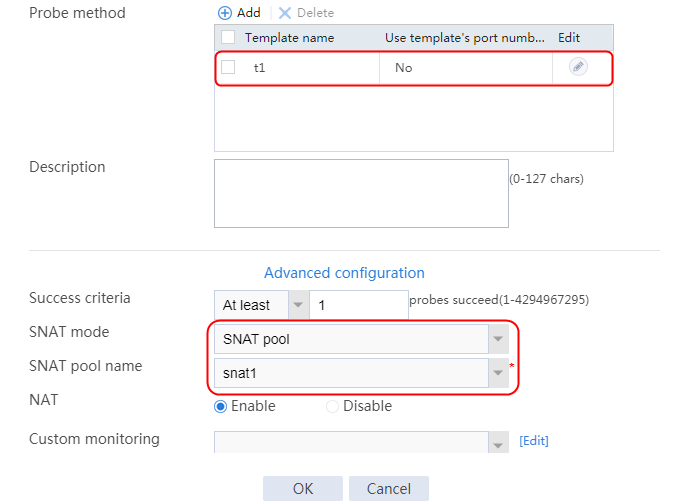
3. Click OK.
Figure 517 Creating server farm sf2
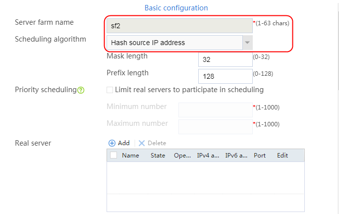

4. Click OK.
Configuring real servers
1. Navigate to the LB > Application Load Balancing > Server Farms page.
2. Edit server farm sf1, and click Add to create a real server. Specify the real server name as rs1 and IP address as 7.0.0.2.
Figure 518 Adding an IPv4 real server

Figure 519 Creating a real server

3. Click OK.
4. Create real server rs2 in the same way real server rs1 is created. Configure the IPv4 address for real server rs2 as 7.0.0.3.
Figure 520 Server farm information
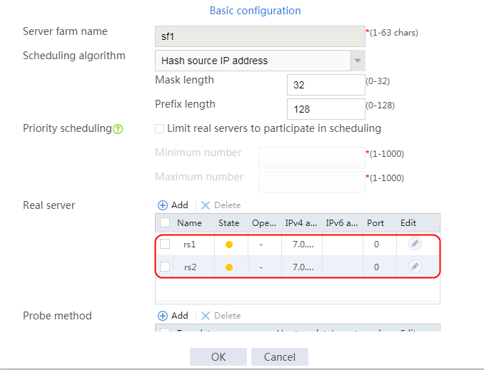
5. Click OK.
6. Navigate to the LB > Application Load Balancing > Server Farms page.
7. Edit server farm sf2, and click Add to create a real server. Specify the real server name as rs11 and the IPv6 address as 7::2.
Figure 521 Adding an IPv6 real server

Figure 522 Creating a real server

8. Click OK.
9. Create real server rs12 in the same way rs11 is created. Configure the IPv6 address for real server rs12 as 7::3.
Figure 523 Server farm information
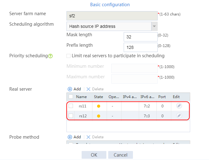
10. Click OK.
Configuring virtual servers
1. Navigate to the LB > Application Load Balancing > Virtual Servers page.
2. Click Create to create virtual servers named vs1 and vs2, specify their IP addresses as 200::1 and 61.159.4.100, and specify server farms sf1 and sf2 for them, respectively. Specify the type as TCP, set the port number to 80, enable the Layer 7 operation mode, and enable the virtual server feature.
Figure 524 Creating virtual server vs1
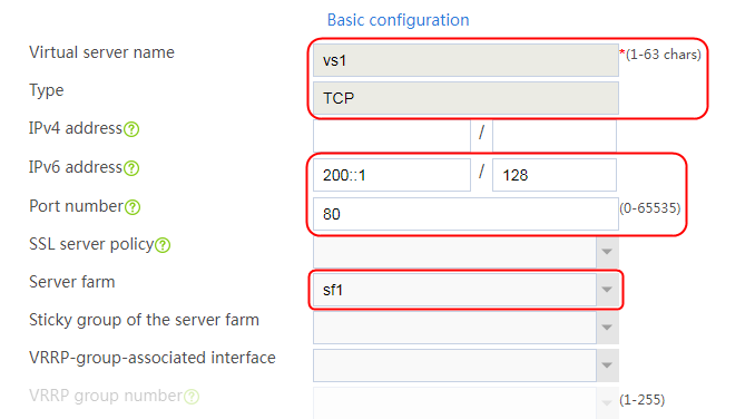

3. Click OK.
Figure 525 Creating virtual server vs2
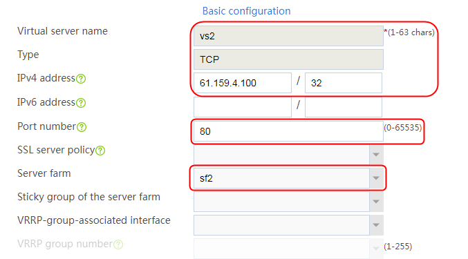
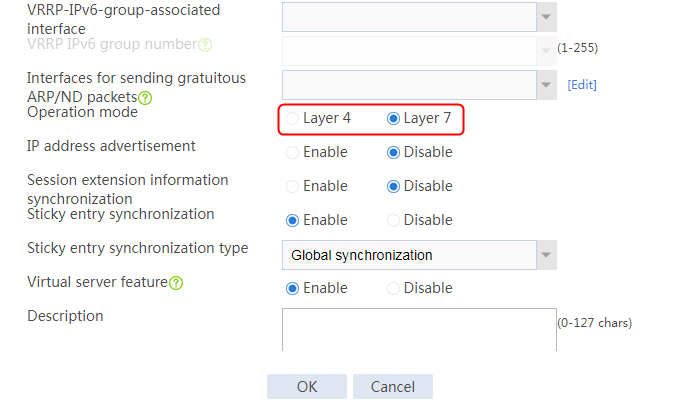
4. Click OK.
Verifying the configuration
Verify that the host can access the HTTP server through http://61.159.4.100 and http://200::1 successfully, and you can view the virtual server and real server statistics.
Figure 526 LB session information
![]()
Configuration files
#
nqa template icmp icmp
#
loadbalance snat-pool snat_v6
ipv6 range start 7::1 end 7::1
#
loadbalance snat-pool snat_v4
ip range start 7.0.0.1 end 7.0.0.1
#
server-farm sf1
predictor hash address source
snat-pool snat_v4
probe icmp
success-criteria at-least 1
real-server rs1 port 0
success-criteria at-least 1
real-server rs2 port 0
success-criteria at-least 1
#
server-farm sf2
predictor hash address source
snat-pool snat_v6
probe icmp
success-criteria at-least 1
real-server rs11 port 0
success-criteria at-least 1
real-server rs12 port 0
success-criteria at-least 1
#
real-server rs1
ip address 7.0.0.2
#
real-server rs11
ipv6 address 7::2
#
real-server rs12
ipv6 address 7::3
#
real-server rs2
ip address 7.0.0.3
#
virtual-server vs_v6 type tcp
port 80
virtual ipv6 address 200::1
default server-farm sf1
application-mode enable
service enable
#
virtual-server vs_v4 type tcp
port 80
virtual ip address 61.159.4.100
default server-farm sf2
application-mode enable
service enable
#
Example: Configuring NAT64 load balancing for AFT (IPv4-to-IPv6)
Network configuration
As shown in Figure 527, enable the LB device to distribute user requests from IPv4 address 10.0.0.0/24 in a company to the FTP servers with IPv6 addresses 7::2 and 7::3 on the internet.
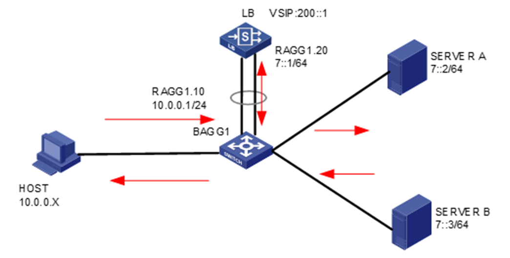
Analysis
To implement NAT64, complete the following configuration on the LB device:
· Configure an IPv6-to-IPv4 source address static translation policy to translate the specified destination IPv4 address into an IPv6 address.
· Configure a NAT64 prefix to translate the matching source IPv4 addresses into IPv6 addresses.
· Configure an IPv4-to-IPv6 source address dynamic translation policy to translate the source IP addresses matching the NAT64 prefix into IPv6 addresses.
Software versions used
This configuration example was created and verified on Feature 1160P16 of L1070.
Restrictions and guidelines
When you configure NAT64 load balancing for AFT (IPv4-to-IPv6), follow these restrictions and guidelines:
· Enable AFT for associated interfaces.
· A translation policy can take effect only after you specify a NAT64 prefix or general prefix for it.
· Enable IP address advertisement for the virtual server.
· Configure a specific IP address for the virtual server, instead of a network address.
· Configuration of both LB and AFT is supported only at Layer 4.
Procedures
Assigning IP addresses to interfaces
Details not shown.
Enabling AFT
1. Navigate to the Network > AFT page.
2. Select interfaces and enable AFT for them.
Figure 528 Enabling AFT for the interfaces

Figure 529 AFT enabled for the interfaces

Configuring AFT prefix and policy settings
1. Navigate to the Objects > ACL > IPv4 ACL page.
2. Click Create to create basic ACL 2000.
Figure 530 Creating an ACL
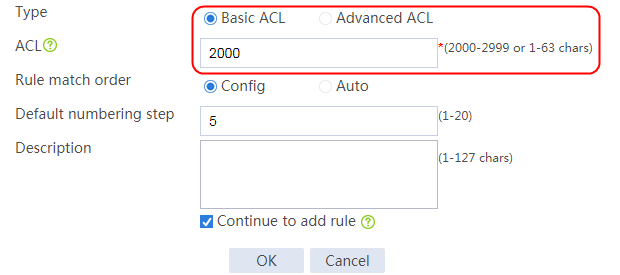
3. Click OK to add a rule that permits user requests sourced from network 10.0.0.0/24 to access the Internet.
Figure 531 Adding a rule
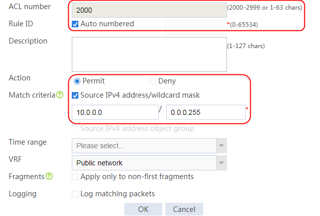
4. Click OK to add another rule that denies user requests sourced from any other IP addresses.
Figure 532 Adding another rule
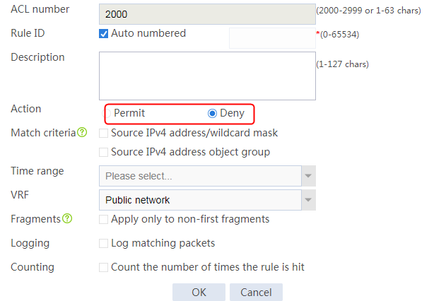
5. Click Cancel to complete the configuration.
Figure 533 Completing ACL configuration
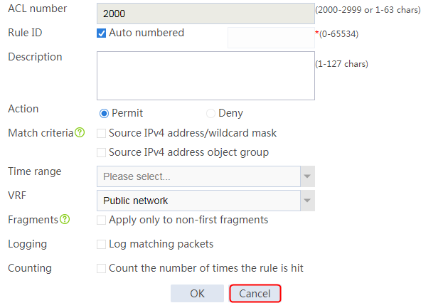
Figure 534 ACL rule information
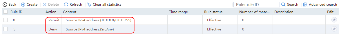
6. Navigate to the Network > ACL > NAT64 Prefixes page.
7. Click Create to create NAT64 prefix 2018::, and specify the prefix length as 96.
This prefix will be used in the IPv4-to-IPv6 source address dynamic translation policy to translate matching source IP addresses into IPv6 addresses.
Figure 535 Creating a NAT64 prefix

8. Click OK.
9. Execute the following command on the LB device to configure an IPv4-to-IPv6 source address dynamic translation policy to translate source addresses matching ACL 2000 into IPv6 addresses based on the NAT64 prefix. (The configuration is not available on the Web interface.)
[Sysname] aft v4tov6 source acl number 2000 prefix-nat64 2018:: 96
10. Navigate to the Network > AFT > AFT Policies page.
11. Click Create to create an IPv6-to-IPv4 source address static translation policy. Specify the translation method as v6tov4, the IPv4 address as 61.232.0.2, and the IPv6 address as 200::1.
Figure 536 IPv6-to-IPv4 source address static translation policy
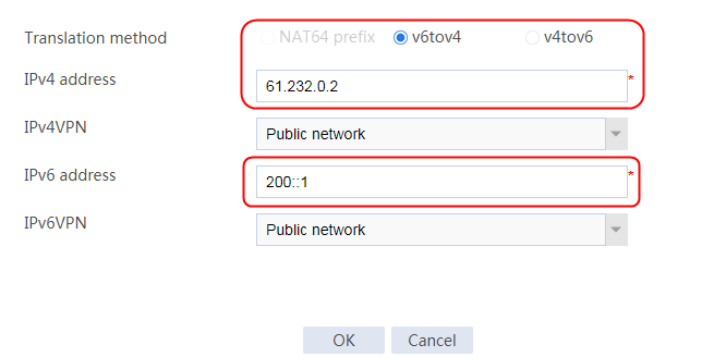
12. Click OK.
Configuring a health monitoring template
1. Navigate to the LB > Global Configuration > Health Monitoring page.
2. Click Create to create a template named tcp, and specify the type as TCP.
Figure 537 Creating a health monitoring template
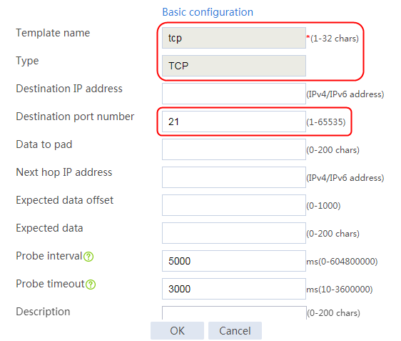
3. Click OK.
Creating a server farm
1. Navigate to the LB > Application Load Balancing > Server Farms page.
2. Click Create to create a server farm named sf2. Specify the scheduling algorithm as Hash source IP address and probe method as tcp.
Figure 538 Creating server farm sf2

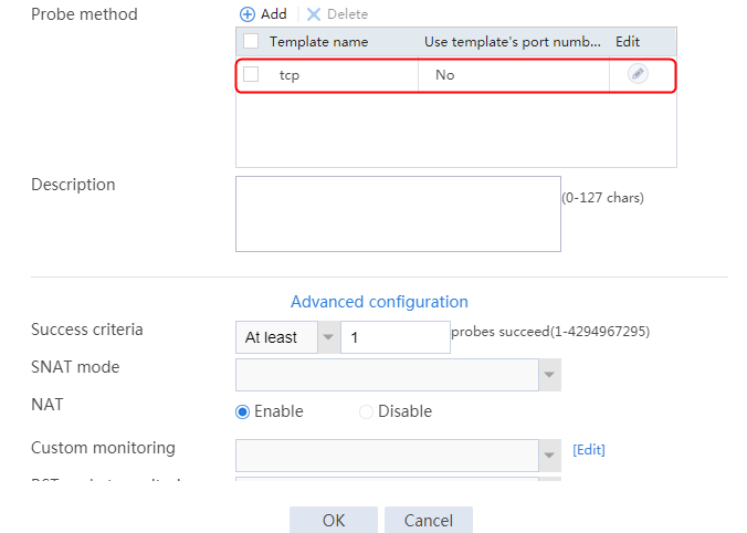
3. Click OK.
Configuring real servers
1. Navigate to the LB > Application Load Balancing > Server Farms page.
2. Edit server farm sf2, and click Add to create a real server. Specify the real server name as rs11 and the IPv6 address as 7::2.
Figure 539 Adding an IPv6 real server

Figure 540 Creating a real server
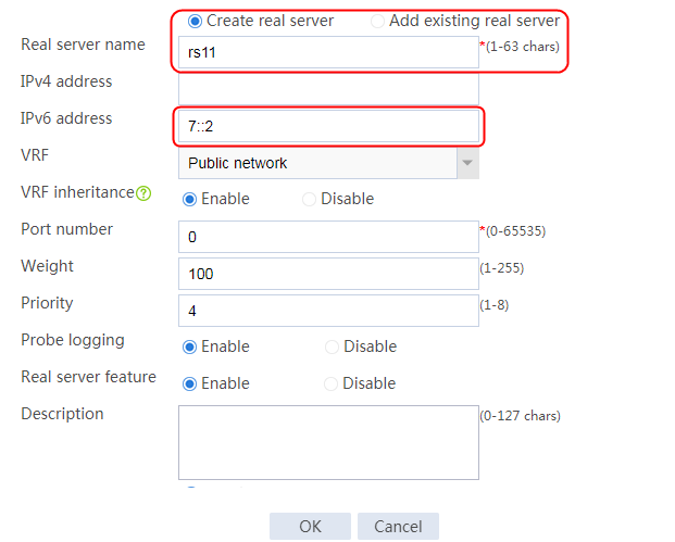
3. Click OK.
4. Create real server rs12 in the same way rs11 is created. Configure the IPv6 address for real server rs12 as 7::3.
Figure 541 Server farm information

5. Click OK.
Configuring a virtual server
1. Navigate to the LB > Application Load Balancing > Virtual Servers page.
2. Click Create to create a virtual server named vs_v6. Specify the type as TCP and virtual server IP address as 200::1. Specify server farm sf2, enable IP address advertisement, and enable the virtual server feature.
Figure 542 Creating virtual server vs1
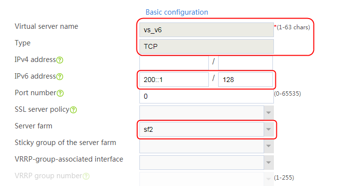
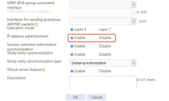
Verifying the configuration
Execute the ftp 61.232.0.2 command to verify that the host can access the FTP server successfully. You can view the AFT session statistics on the LB device.
Figure 543 Successful service access
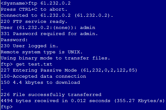
Display AFT session information. You can see that an IPv4 session and an IPv6 session have been created, corresponding to the packets before and after the translation, respectively.
<Sysname>display aft session ipv4 verbose
Slot 1:
Initiator:
Source IP/port: 10.0.0.22/62853
Destination IP/port: 61.232.0.2/21
DS-Lite tunnel peer: -
VPN instance/VLAN ID/Inline ID: -/-/-
Protocol: TCP(6)
Inbound interface: Route-Aggregation1.10
Responder:
Source IP/port: 61.232.0.2/21
Destination IP/port: 10.0.0.22/62853
DS-Lite tunnel peer: -
VPN instance/VLAN ID/Inline ID: -/-/-
Protocol: TCP(6)
Inbound interface: Route-Aggregation1.20
State: TCP_ESTABLISHED
Application: FTP
Rule ID: -/-/-
Rule name:
Start time: 2021-09-28 20:52:37 TTL: 3583s
Initiator->Responder: 0 packets 0 bytes
Responder->Initiator: 0 packets 0 bytes
Total sessions found: 1
<Sysname>display aft session ipv6 verbose
Slot 1:
Initiator:
Source IP/port: 2018::A00:16/62853
Destination IP/port: 200::1/21
VPN instance/VLAN ID/Inline ID: -/-/-
Protocol: TCP(6)
Inbound interface: Route-Aggregation1.10
Responder:
Source IP/port: 7::2/21
Destination IP/port: 2018::A00:16/62853
VPN instance/VLAN ID/Inline ID: -/-/-
Protocol: TCP(6)
Inbound interface: Route-Aggregation1.20
State: TCP_ESTABLISHED
Application: FTP
Rule ID: -/-/-
Rule name:
Start time: 2021-09-28 20:52:37 TTL: 3579s
Initiator->Responder: 0 packets 0 bytes
Responder->Initiator: 0 packets 0 bytes
Total sessions found: 1
<Sysname>
Configuration files
#
nqa template tcp tcp
destination port 21
#
interface Route-Aggregation1.10
ip address 10.0.0.1 255.255.255.0
aft enable
vlan-type dot1q vid 10
#
interface Route-Aggregation1.20
aft enable
vlan-type dot1q 20
ipv6 address 7::1/64
#
acl basic 2000
rule 0 permit source 10.0.0.0 0.0.0.255
rule 5 deny
#
aft prefix-nat64 2018:: 96
aft v6tov4 source 200::1 61.232.0.2
aft v4tov6 source acl number 2000 prefix-nat64 2018:: 96
#
server-farm sf2
predictor hash address source
probe tcp
success-criteria at-least 1
real-server rs11 port 0
success-criteria at-least 1
real-server rs12 port 0
success-criteria at-least 1
#
real-server rs11
ipv6 address 7::2
#
real-server rs12
ipv6 address 7::3
#
virtual-server vs_v6 type tcp
virtual ipv6 address 200::1
default server-farm sf2
route-advertisement enable
connection-sync enable
sticky-sync enable global
service enable
#
Example: Configuring NAT64 load balancing for AFT (IPv6-to-IPv4)
Network configuration
As shown in Figure 544, the Internet has been upgraded to IPv6, but the internal network of the company is still an IPv4 network. The company wants to provide FTP services for users on the Internet, and uses IPv6 address 300::2 to access the Internet.
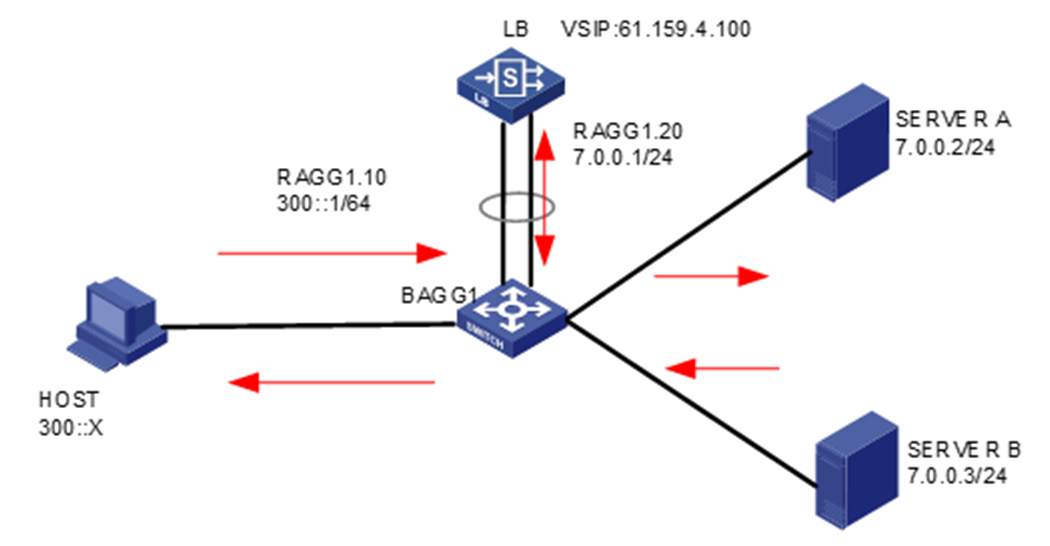
Analysis
To implement NAT64, complete the following configuration on the LB device:
· Configure an IPv4-to-IPv6 source address static translation policy to map an IPv6 address to the FTP server address in the IPv4 network. The hosts on the Internet can access the FTP server through this IPv6 address. When the LB device receives a packet destined to the IPv6 address, it translates the destination address in the packet to the specified IPv4 address.
· Configure an IPv6-to-IPv4 source address dynamic translation policy to translate the source addresses of IPv6 packets from the Internet into IPv4 addresses 7.0.0.200 and 7.0.0.201.
Software versions used
This configuration example was created and verified on Feature 1160P16 of L1070.
Restrictions and guidelines
When you configure NAT64 load balancing for AFT (IPv6-to-IPv4), follow these restrictions and guidelines:
· Enable AFT for associated interfaces.
· A translation policy can take effect only after you specify a NAT64 prefix or general prefix for it.
· Enable IP address advertisement for the virtual server.
· Configure a specific IP address for the virtual server, instead of a network address.
· Configuration of both LB and AFT is supported only at Layer 4.
Procedures
Assigning IP addresses to interfaces
Details not shown.
Enabling AFT
1. Navigate to the Network > AFT page.
2. Select interfaces and enable AFT for them.
Figure 545 Enabling AFT for the interfaces
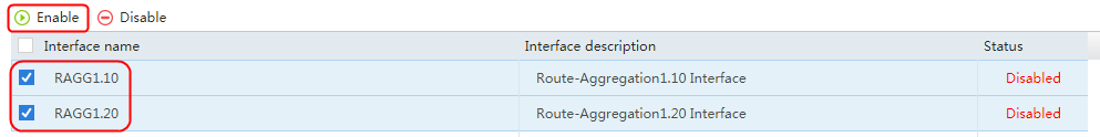
Figure 546 AFT enabled for the interfaces
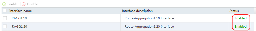
Configuring AFT prefix and policy settings
1. Navigate to the Objects > ACL > IPv6 ACL page.
2. Click Create to create basic ACL 2000.
Figure 547 Creating an ACL
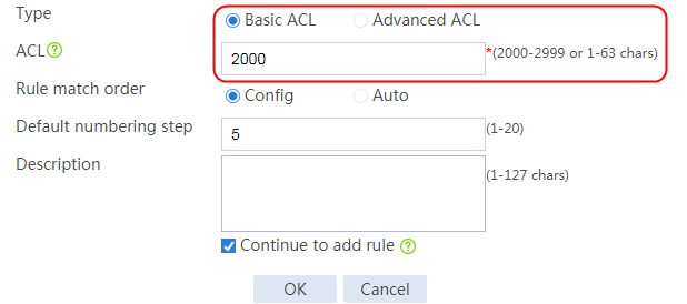
3. Click OK to add a rule that permits user requests sourced from network 300:: 64.
Figure 548 Adding a rule
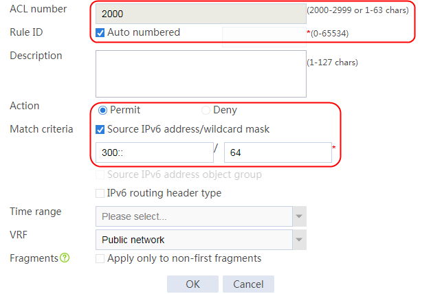
4. Click OK to add another rule that denies user requests sourced from any other IPv6 addresses.
Figure 549 Adding another rule
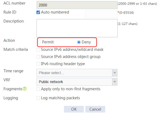
5. Click Cancel to complete the configuration.
Figure 550 Completing ACL configuration
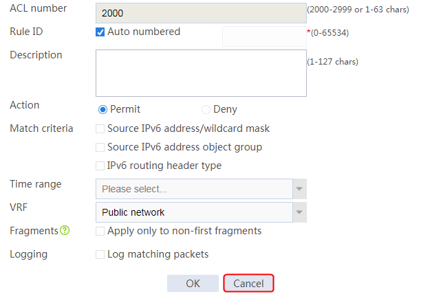
Figure 551 ACL rule information
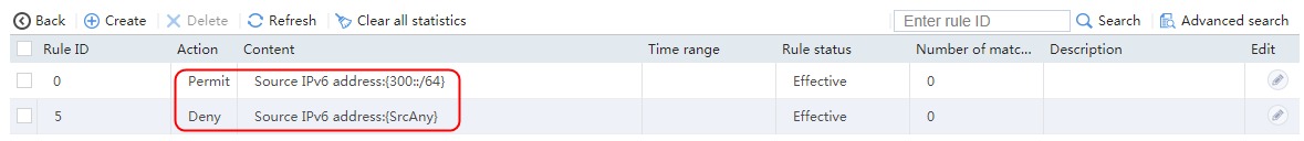
6. Navigate to the Network > ACL > NAT64 Prefixes page.
7. Click Create to create NAT64 prefix 2018::, and specify the prefix length as 96.
This prefix will be used to translate matching destination IPv6 addresses into an IPv4 addresses.
Figure 552 Creating a NAT64 prefix
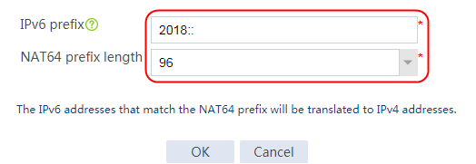
8. Click OK.
9. Navigate to the Objects > Object Groups > AFT Address Groups page, and click Create to create an AFT address group. Specify the start IP address as 7.0.0.200 and the end IP address as 7.0.0.203.
Figure 553 Configuring an AFT address group
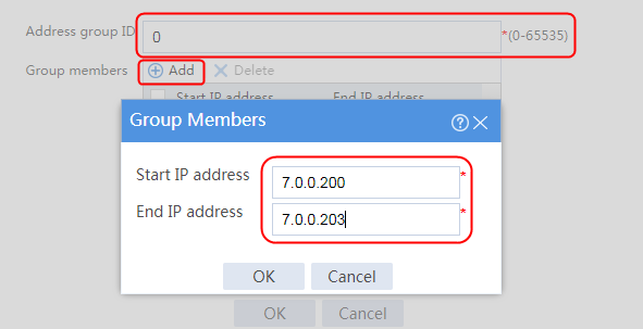
10. Click OK.
Figure 554 AFT address group information
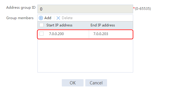
11. Navigate to the Network > AFT > AFT Policies page.
12. Click Create to create an IPv4-to-IPv6 source address dynamic translation policy to translate source addresses matching ACL 2000 into IPv4 addresses based on the NAT64 prefix. Specify translation method NAT64 prefix, ACL 2000 for packet matching, and AFT address group 0.
Figure 555 Creating an AFT policy
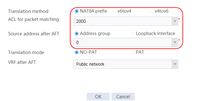
13. Click OK.
Configuring a health monitoring template
1. Navigate to the Objects > Health Monitoring page.
2. Click Create to create a template named tcp, and specify the type as TCP.
Figure 556 Creating a health monitoring template

3. Click OK.
Creating a server farm
1. Navigate to the LB > Application Load Balancing > Server Farms page.
2. Click Create to create a server farm named sf1. Specify the scheduling algorithm as Hash source IP address and probe method as tcp.
Figure 557 Creating server farm sf1


3. Click OK.
Configuring real servers
1. Navigate to the LB > Application Load Balancing > Server Farms page.
2. Edit server farm sf1, and click Add to create a real server. Specify the real server name as rs1 and IP address as 7.0.0.2.
Figure 558 Adding a real server
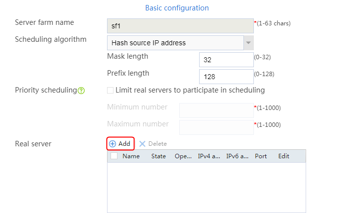
Figure 559 Creating a real server
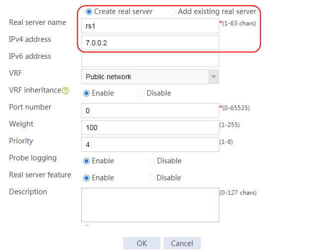
3. Click OK.
4. Create real server rs2 in the same way real server rs1 is created. Configure the IPv4 address for real server rs2 as 7.0.0.3.
Figure 560 Server farm information

5. Click OK.
Configuring a virtual server
1. Navigate to the LB > Application Load Balancing > Virtual Servers page.
2. Click Create to create a virtual server named vs_v4. Specify the type as TCP and virtual server IP address as 61.159.4.100. Specify server farm sf1, enable IP address advertisement, and enable the virtual server feature.
Figure 561 Creating virtual server vs_v4
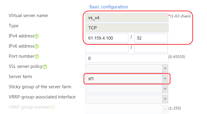

3. Click OK.
Verifying the configuration
Execute the ftp ipv6 2018::61.159.4.100 command to verify that the host can access the FTP server successfully. You can view the virtual server, real server, and AFT session statistics on the LB device.
Figure 562 Successful service access
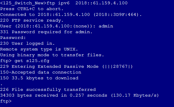
Display AFT session information. You can see that an IPv6 session and an IPv4 session have been created, corresponding to the packets before and after the translation, respectively.
<Sysname>display aft session ipv6 verbose
Slot 1:
Initiator:
Source IP/port: 300::2/63966
Destination IP/port: 2018::3D9F:464/21
VPN instance/VLAN ID/Inline ID: -/-/-
Protocol: TCP(6)
Inbound interface: Route-Aggregation1.10
Responder:
Source IP/port: 2018::3D9F:464/21
Destination IP/port: 300::2/63966
VPN instance/VLAN ID/Inline ID: -/-/-
Protocol: TCP(6)
Inbound interface: Route-Aggregation1.20
State: TCP_ESTABLISHED
Application: FTP
Rule ID: -/-/-
Rule name:
Start time: 2021-09-29 15:03:55 TTL: 3596s
Initiator->Responder: 0 packets 0 bytes
Responder->Initiator: 0 packets 0 bytes
Total sessions found: 1
<Sysname>
<Sysname>display aft session ipv4 verbose
Slot 1:
Initiator:
Source IP/port: 7.0.0.203/63966
Destination IP/port: 61.159.4.100/21
DS-Lite tunnel peer: -
VPN instance/VLAN ID/Inline ID: -/-/-
Protocol: TCP(6)
Inbound interface: Route-Aggregation1.10
Responder:
Source IP/port: 7.0.0.2/21
Destination IP/port: 7.0.0.203/63966
DS-Lite tunnel peer: -
VPN instance/VLAN ID/Inline ID: -/-/-
Protocol: TCP(6)
Inbound interface: Route-Aggregation1.20
State: TCP_ESTABLISHED
Application: FTP
Rule ID: -/-/-
Rule name:
Start time: 2021-09-29 15:03:55 TTL: 3592s
Initiator->Responder: 0 packets 0 bytes
Responder->Initiator: 0 packets 0 bytes
Total sessions found: 1
Configuration files
#
nqa template tcp tcp
destination port 21
#
interface Route-Aggregation1.10
aft enable
vlan-type dot1q vid 10
ipv6 address 300::1/64
#
interface Route-Aggregation1.20
ip address 7.0.0.1 255.255.255.0
aft enable
vlan-type dot1q vid 20
#
acl ipv6 basic 2000
rule 0 permit source 300::/64
rule 5 deny
#
aft address-group 0
address 7.0.0.200 7.0.0.203
#
aft prefix-nat64 2018:: 96
aft v6tov4 source acl ipv6 number 2000 address-group 0 no-pat
#
server-farm sf1
predictor hash address source
probe tcp
success-criteria at-least 1
real-server rs1 port 0
success-criteria at-least 1
real-server rs2 port 0
success-criteria at-least 1
#
real-server rs1
ip address 7.0.0.2
#
real-server rs2
ip address 7.0.0.3
#
virtual-server vs_v6 type tcp
virtual ipv6 address 200::1
default server-farm sf2
route-advertisement enable
connection-sync enable
sticky-sync enable global
service enable
#
Connection limit configuration example
Network configuration
As shown in the Figure 563, a host accesses three servers through the LB device. The three servers Server A, Server B, and Server C in the public network can all provide HTTP services. The host traffic will be load-shared among the three servers. To avoid network congestion and resource overconsumption, the LB device must meet the following requirements:
· Allow a maximum of 200 connections to be established to Server A.
· Allow each IP address in network 10.0.1.16/28 to initiate a maximum of 10 connections.
· Distribute packets carrying a specific cookie value to Server A without limiting the number of connections initiated from the associated client.

Analysis
To implement the connection limit feature, complete the following configuration on the LB device:
· Configure server farm and real server settings.
· Configure a connection limit policy to allow a maximum of 10 connections from each IP address on a specific network.
· Configure a sticky group based on cookie insertion and disable the override limits function.
· Configure a virtual server, and specify a server farm, a sticky group, and a connection limit policy for it.
Software versions used
This configuration example was created and verified on Feature 1160P16 of L1070.
Restrictions and guidelines
When you configure the connection limit feature, follow these restrictions and guidelines:
· Disable the override limits function for the sticky group.
· For cookie-based session stickiness, the cookie carried by the host must be consistent with that allocated to the real server. You can view the cookies on real servers through a command.
· In the connection limit rule, select the Source IP address and Destination IP address options for Limit by.
Procedures
Perform the following configuration on the LB device.
Assigning IP addresses to interfaces
Details not shown.
Creating a health monitoring template
1. Navigate to the LB > Global Configuration > Health Monitoring page.
2. Click Create to create a template named t1, specify the type as HTTP, and set the expected status code to 200.
Figure 564 Creating a health monitoring template

3. Click OK.
Configuring a server farm
1. Navigate to the LB > Application Load Balancing > Server Farms page.
2. Click Create to create a server farm named sf1. Specify the scheduling algorithm as Round robin and probe method as t1.
Figure 565 Creating a server farm
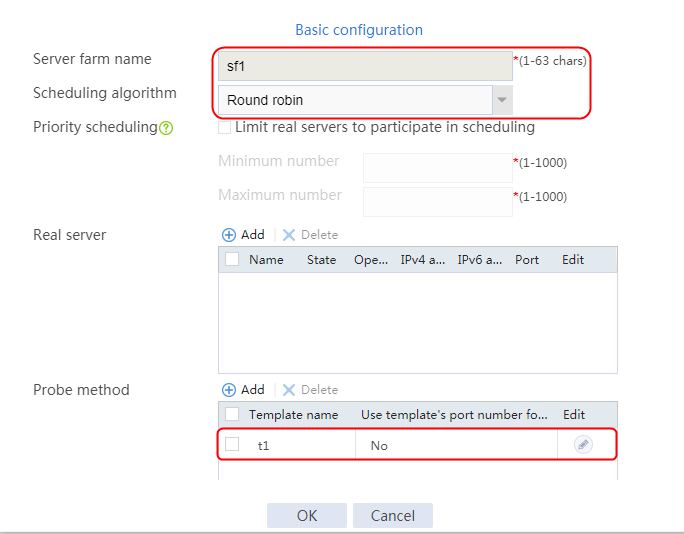
3. Click OK.
Configuring real servers
1. Navigate to the LB > Application Load Balancing > Server Farms page.
2. Edit server farm sf1, and create a real server. Specify the real server name as rs1, the IP address as 192.168.1.1, and the maximum number of connections as 200.
Figure 566 Adding a real server
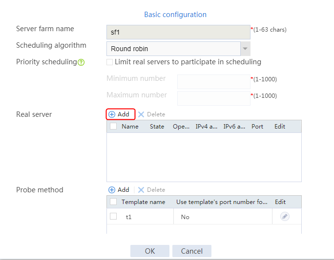
Figure 567 Creating a real server
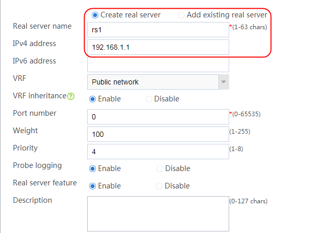
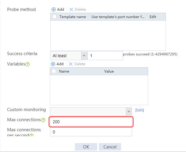
3. Click OK.
4. Create real servers rs2 and rs3 in the same way real server rs1 is created. Configure the IPv4 addresses as 192.168.1.2 and 192.168.1.3 for real servers rs2 and rs3, respectively. Do not set the maximum connection limit for rs2 and rs3.
Figure 568 Server farm information
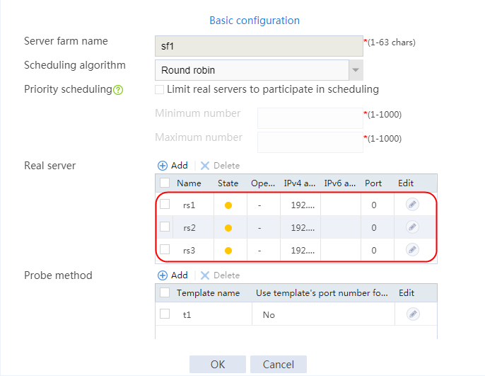
Configuring a sticky group
1. Navigate to the LB > Global Configuration > Sticky Groups page.
2. Click Create to create a sticky group named cookie. Set the type to HTTP-cookie, the cookie stickiness to Cookie insertion, and the cookie name to X-LB. Disable the override limits function.
Figure 569 Creating a sticky group cookie
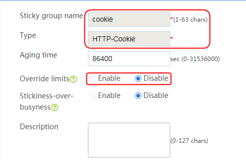
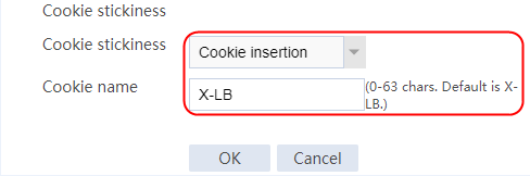
3. Click OK.
Configuring an advanced ACL
1. Navigate to the Object > ACL > IPv4 ACL page, and click Create. Specify the type as Advanced ACL and the ACL number as 3001.
Figure 570 Creating an advanced ACL rule 3001
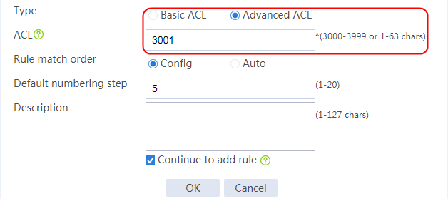
2. Click OK. On the new IPv4 advanced ACL rule page that opens, add an ACL rule. Select Source IPv4 address/wildcard mask and Destination IPv4 address/wildcard mask for Match criteria. Specify the source IPv4 address/wildcard mask as 10.0.1.16/0.0.0.15, and the destination IPv4 address/wildcard mask as 61.159.4.100/0.0.0.0. Clear the Continue to add next rule option.
Figure 571 Creating a rule for advanced ACL 3001
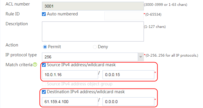
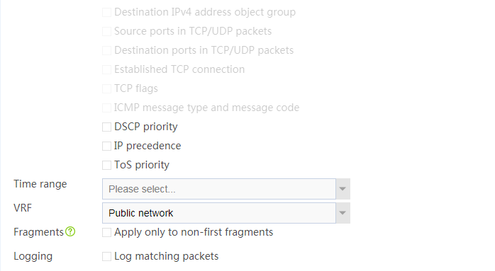

3. Click OK.
Configuring a connection limit policy
1. Navigate to the LB > Application Load Balancing > Advanced Policies > Connection Limit Policy page.
2. Click Create to add a connection limit policy named lp.
3. Click Create to add a rule. Specify the type as IPv4 ACL and the ACL number as 3001, select Source IP address and Destination IP address for Limit by, and enter 10 for the upper and lower limits.
Figure 572 Creating a connection limit policy
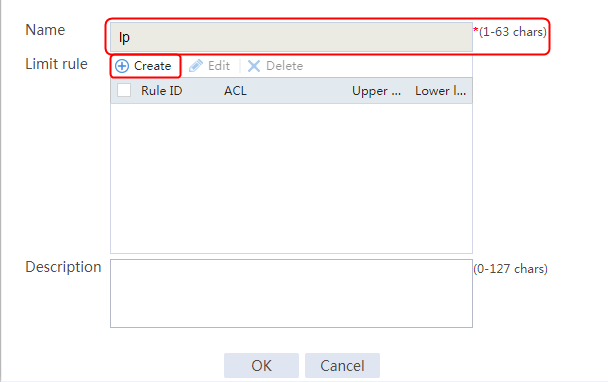
Figure 573 Creating a limit rule
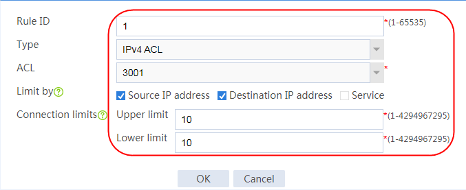
Figure 574 Creating a connection limit policy rule
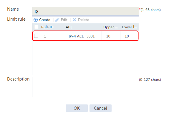
4. Click OK.
Configuring a virtual server
1. Navigate to the LB > Application Load Balancing > Virtual Servers page.
2. Create a virtual server named vs. Specify the type as HTTP, the IPv4 address as 61.159.4.100, and the port number as 80. Specify server farm sf, server farm sticky group cookie, and connection limit policy lp. Enable the virtual server feature, and then click OK.
Figure 575 Creating a virtual server
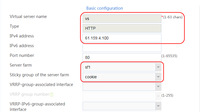
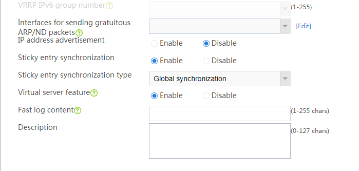
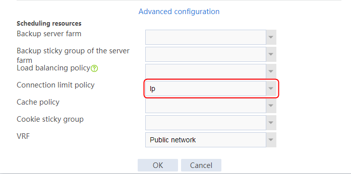
3. Click OK.
Viewing the cookie value of server farm members on the device
Execute the following command to view the cookie value of server farm members on the device (not available on the Web interface).
<Sysname>display sticky virtual-server brief
Slot 1:
Sticky type Sticky method Sticky key Virtual server Real-server/Link
HTTP cookie Cookie Insert 2.0.74232acd.0 vs 192.168.1.1:0
HTTP cookie Cookie Insert 2.1.d7ecc40e.0 vs 192.168.1.2:0
HTTP cookie Cookie Insert 2.2.ac21e602.0 vs 192.168.1.3:0
Verifying the configuration
Clearing virtual server and real server statistics
1. Clear virtual server and real server statistics for accurate verification result, and then inject traffic for verification.
2. Navigate to the Monitor > Application Load Balancing > Virtual Servers > Real-time Statistics page. Select virtual server vs, and click Clear to clear virtual server statistics.
Figure 576 Clearing virtual server statistics
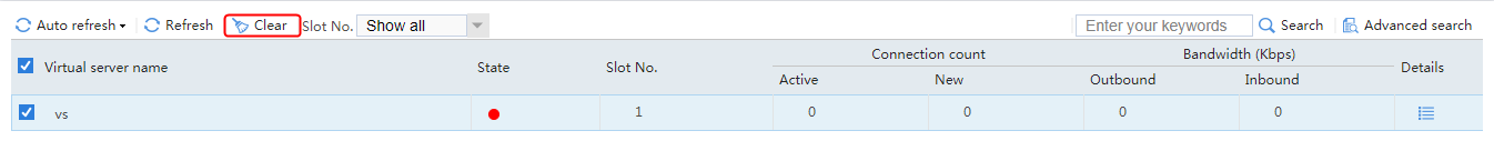
3. Navigate to the Monitor > Application Load Balancing > Real Servers > Real-time Statistics page. Click Clear to clear server farm member statistics.
Figure 577 Clearing server farm statistics
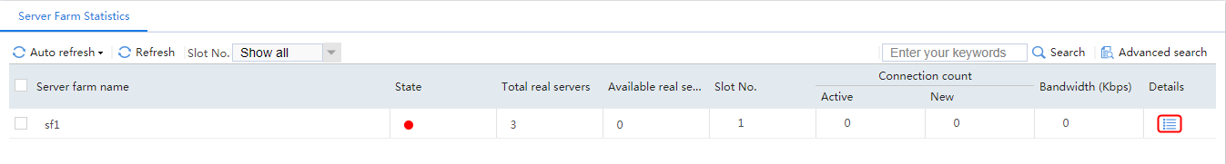
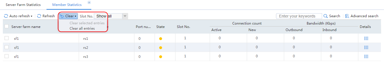
4. View the detailed statistics of the virtual server and each server farm member by clicking the Details icon on the virtual server statistics page and the server farm member statistics page.
Figure 578 Viewing the detailed virtual server statistics
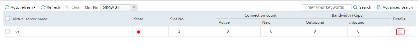
Figure 579 Viewing the detailed server farm member statistics
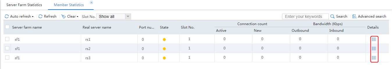
Limiting connections on Server A
Initiate 3000 connections to the virtual server from 100 source addresses not matching the connection limit policy.
The statistics shows that the numbers of connections assigned to Sever A, Server B, and Server C are 200, 1400, and 1400, respectively. All service connections are successfully established.
Figure 580 Statistics of real server rs1
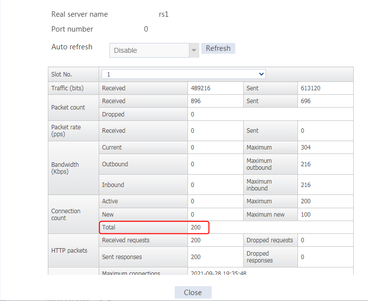
Figure 581 Statistics of real server rs2
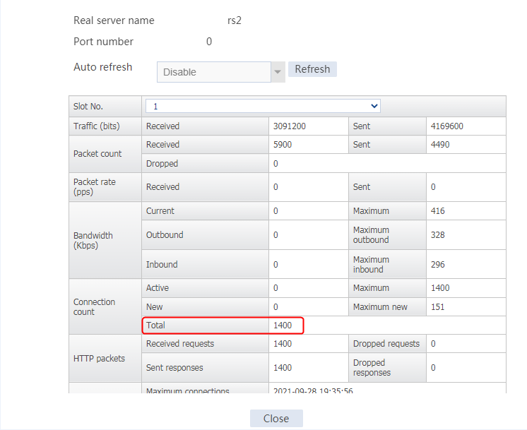
Figure 582 Statistics of real server rs3
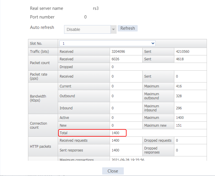
Figure 583 Statistics of the virtual server
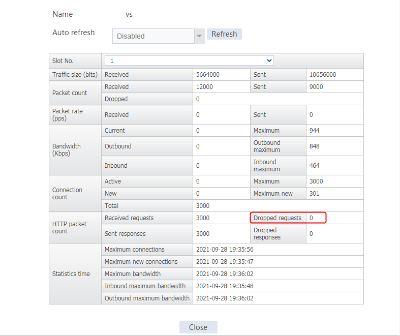
Limiting connections initiated from the specified network
Clear the virtual server and server farm member statistics. Then, initiate 3000 connections to the virtual server from 100 source addresses in the network specified in the connection limit policy.
The statistics shows that the numbers of connections assigned to Sever A, Server B, and Server C are 200, 1240, and 1240, respectively. A number of 320 packet are lost.
Figure 584 Statistics of real server rs1

Figure 585 Statistics of real server rs2

Figure 586 Statistics of real server rs3

Figure 587 Statistics of the virtual server

Cookie-based session persistence
Clear the virtual server and member statistics. Then, initiate 3000 connections to the virtual server from 100 source addresses in the network specified in the connection limit policy. The client request carries the cookie configured for Sever A.
The statistics shows that the all the 3000 connections are assigned to Sever A. No connections are assigned to Sever B or Sever C.
Figure 588 Statistics of real server rs1
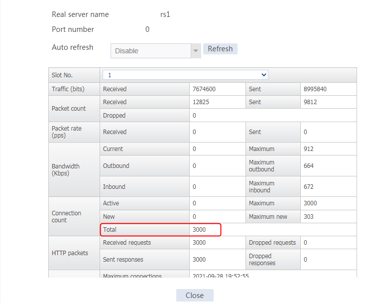
Figure 589 Statistics of real server rs2
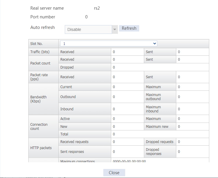
Figure 590 Statistics of real server rs3
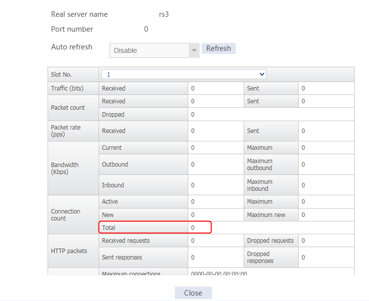
Figure 591 Statistics of the virtual server

Configuration files
#
nqa template http t1
expect status 200
#
acl advanced 3001
rule 0 permit ip source 10.0.1.16 0.0.0.15 destination 61.159.4.100 0
#
sticky-group cookie type http-cookie
override-limit enable
cookie insert
check all-packet
#
server-farm sf1
probe t1
success-criteria at-least 1
real-server rs1 port 0
success-criteria at-least 1
connection-limit max 200
real-server rs2 port 0
success-criteria at-least 1
real-server rs3 port 0
success-criteria at-least 1
#
loadbalance limit-policy lp
limit 1 acl 3001 per-destination per-source amount 10 10
#
real-server rs1
ip address 192.168.1.1
#
real-server rs2
ip address 192.168.1.2
#
real-server rs3
ip address 192.168.1.3
#
virtual-server vs type http
virtual ip address 61.159.4.100
lb-limit-policy lp
default server-farm sf1 sticky cookie
sticky-sync enable global
service enable
#
IPS/AV/WAF-based deep packet inspection configuration example
Network configuration
As shown in Figure 592, the LAN user is connected to the LB device to access the Internet. Enable deep packet inspection for traffic passing through the LB device to identify network attacks and security risks and take relevant actions, protecting the LB device and internal servers.
If the host initiates an IPS/AV/WAF attack, the LB device can identify the attack, logs the event, and take relevant actions (such as drop attack packets) to protect the internal servers.

Analysis
To implement deep packet inspection for the service traffic that passes the LB device, complete the following configuration on the LB device:
· Install an IPS/AV/WAF license.
· Upgrade the IPS/AV/WAF signature library to the latest version.
· Configure the IPS/AV/WAF profile.
· Specify the IPS/AV/WAF profile for the virtual server.
Software versions used
This configuration example was created and verified on Feature 1160P16 of L1070.
Restrictions and guidelines
When you configure IPS/AV/WAF-based deep packet inspection, follow these restrictions and guidelines:
· Make sure the device is installed with an IPS/AV/WAF license and the signature library is upgraded to the latest version.
· After modifying content security configuration (through addition, modification, or deletion), you must click Submit to make your modification take effect.
· Enable system log output for IPS/AV.
· WAF supports only fast log output. You need to enable fast log output to the log host at the CLI.
Procedures
Applying for a license
Details not shown.
Installing the license
1. Navigate to the System > license Config page.
2. Click Install to upload the license file for the specified module.
Figure 593 Installing a license
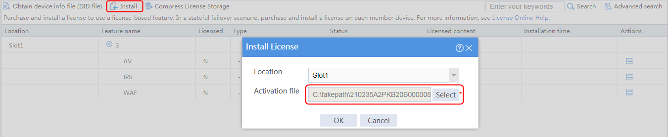
Figure 594 IPS/AV/WAF license information
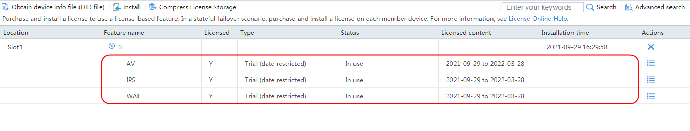
Upgrading the signature library
1. Navigate to the System > Upgrade Center > Signature Upgrade page.
2. Upgrade the IPS/AV/WAF signature library in sequence. The device supports online upgrade, manual upgrade, and scheduled upgrade.
Figure 595 Upgrading a signature library
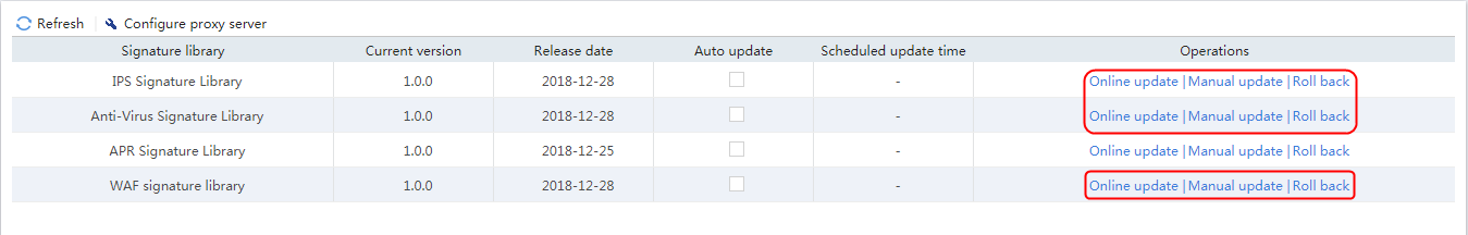
Figure 596 Signature library information
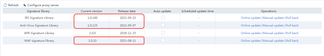
|
|
NOTE: You can the upgrade the IPS/AV/WAF signature library through online upgrade or scheduled upgrade only when you can access the official website of the device.. You can download the IPS/AV/WAF signature library file from the official website, and use the downloaded file to perform manual upgrade. |
Creating an IPS profile (optional)
1. Navigate to the LB > App Security > IPS > Profiles page.
2. Click Create. On the Create IPS Profile page, specify the name as ips, and click OK.
Figure 597 Creating an IPS profile
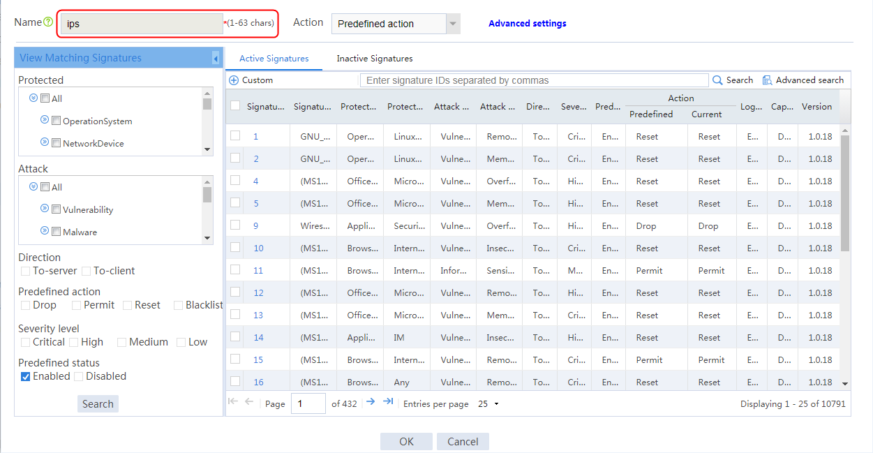
Creating an anti-virus profile (optional)
1. Navigate to the LB > App Security > Anti-Virus > Profiles page.
2. Click Create. On the Create Anti-Virus Profile page, specify the name as av, and click OK.
Figure 598 Creating an anti-virus profile
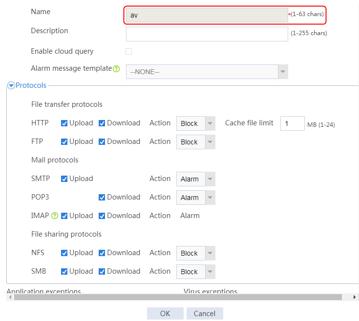
Creating a WAF profile (optional)
1. Navigate to the LB > App Security > WAF > Profiles page.
2. Click Create. On the WAF profile creation page, specify the name as waf, and click OK.
Figure 599 Creating a WAF profile
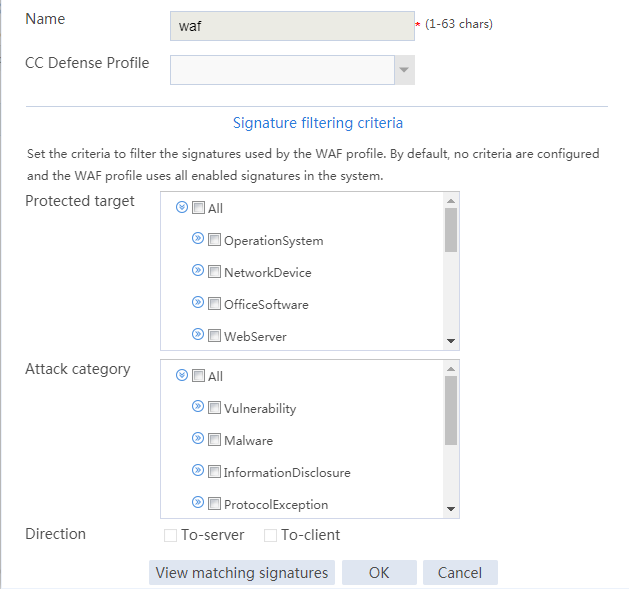
Creating a health monitoring template
1. Navigate to the LB > Global Configuration > Health Monitoring page.
2. Click Create to create a template named t1, specify the type as TCP, and set the destination port number to 80.
Figure 600 Creating a health monitoring template
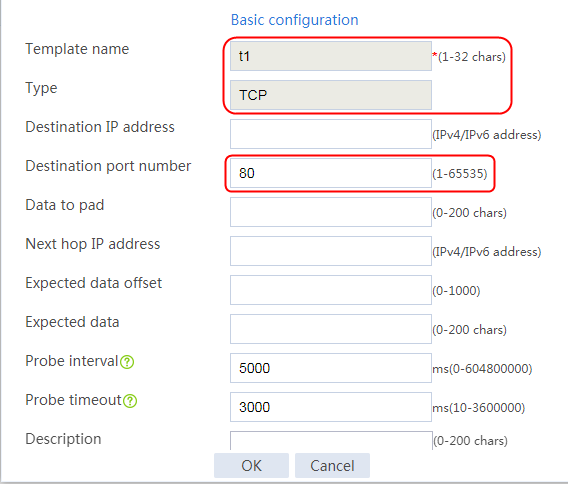
3. Click OK.
Configuring a server farm
1. Navigate to the LB > Application Load Balancing > Server Farms page.
2. Click Create to create a server farm named sf1. Specify the scheduling algorithm as Hash source IP address and probe method as t1.
Figure 601 Creating a server farm
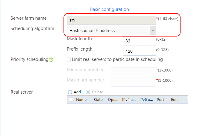

3. Click OK.
Configuring real servers
1. Navigate to the LB > Application Load Balancing > Server Farms page.
2. Edit server farm sf1, and create a real server. Specify the real server name as rs1 and the IP address as 192.168.1.1.
Figure 602 Adding a real server

Figure 603 Creating a real server

3. Click OK.
4. Create real servers rs2 and rs3 in the same way real server rs1 is created. Configure the IPv4 addresses as 192.168.1.2 and 192.168.1.3 for real servers rs2 and rs3, respectively.
Figure 604 Server farm information

Configuring a virtual server
1. Navigate to the LB > Application Load Balancing > Virtual Servers page.
2. Click Create to add the virtual server named vs. Specify the type as TCP, set the IPv4 address to 61.159.4.100/32, enable the virtual server feature, and enable the content security function. Specify the WAF profile waf, IPS profile ips, and anti-virus profile av.
Figure 605 Creating a virtual server
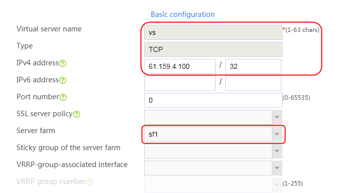
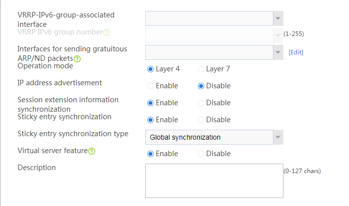
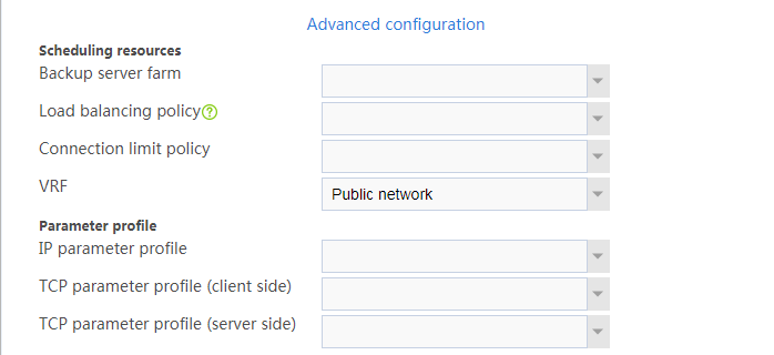
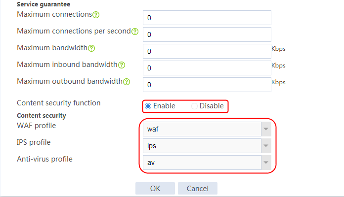
3. Click OK.
4. After modifying content security configuration, click Submit to make the modification take effect, and complete the virtual server configuration.
Figure 606 Completing virtual server configuration

Enabling IPS/AV/WAF logging
1. Navigate to the System > Log Settings > Attack Defense Log Settings page, enable System log for both IPS logs and anti-virus logs, and then click Apply.
Figure 607 Enabling system log for IPS logs and anti-virus logs
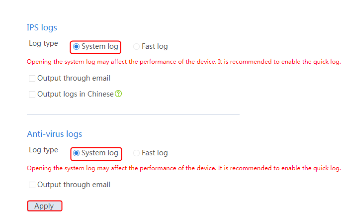
2. Navigate to the System > Log Settings > Basic Settings > Fast Log Output page. Create a log host, specify the log host IP address, and enable WAF logs.
Figure 608 Creating a log host
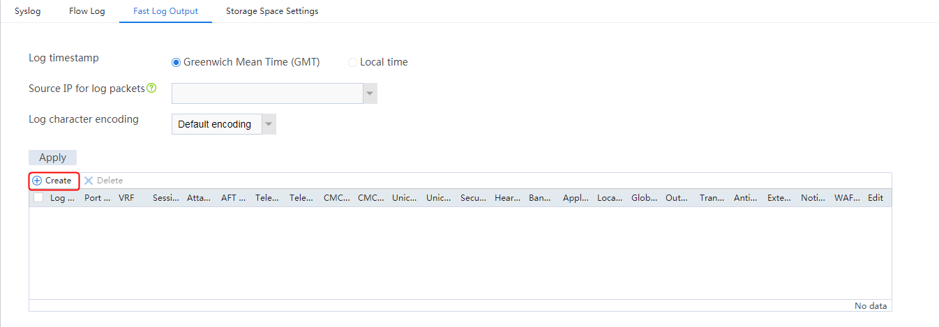
Figure 609 Enabling WAF logs
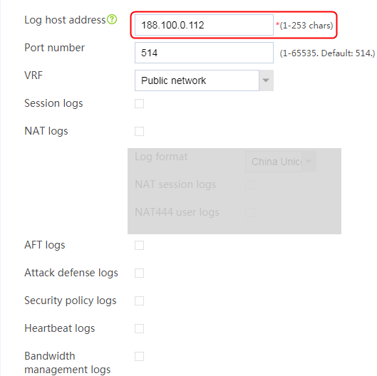
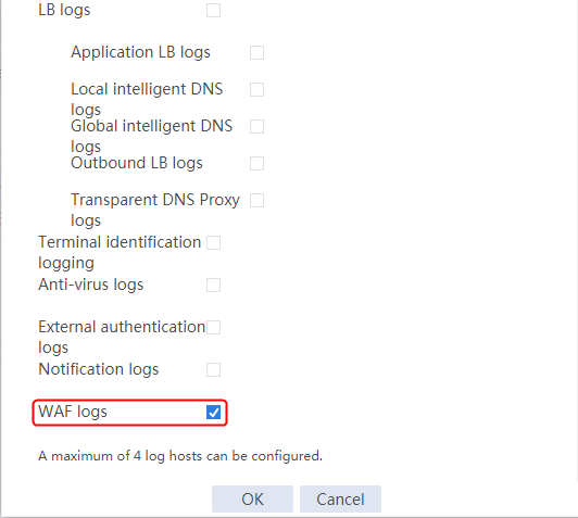
3. Navigate to the System > Log Settings > Basic Settings > Storage Space Settings page to enable the dpi | threat service.
Figure 610 Enabling the dpi | threat service
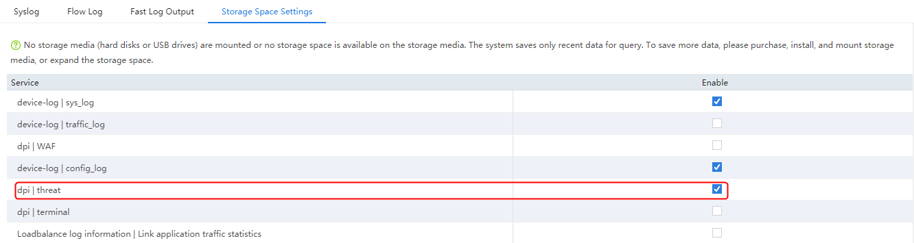
4. Execute the following command to enable fast log output to the log host for WAF (not available on the Web interface).
[Sysname]customlog format dpi waf
Verifying the configuration
Handling IPS attacks
The host sends a request with the following URL through a browser:
http://61.159.4.100/mytest1/export/show2.php?id=2%20%20AND%203206=CONVERT(INT,(CHAR(58)+CHAR(103)+CHAR(115)+CHAR(99)+CHAR(58)+(SELECT%20SUBSTRING((ISNULL(CAST(*%20form%20pangolin_test_table;--%20AS%20NVARCHAR(4000)),CHAR(32))),1,100))+CHAR(58)+CHAR(112)+CHAR(120)+CHAR(117)+CHAR(58)))
The device can detect the attack traffic, intercept the attack, and generate a threat log.
To view the threat log, navigate to the Monitor > Device Logs > Traffic Logs page. Click the Details icon to view the detailed information about the log.
Figure 611 Viewing the threat log
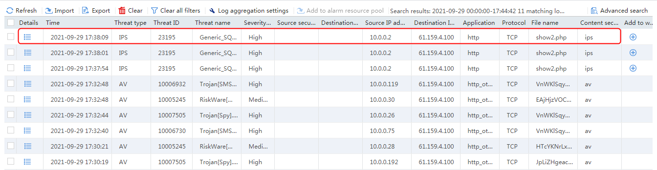
Figure 612 IPS threat log details
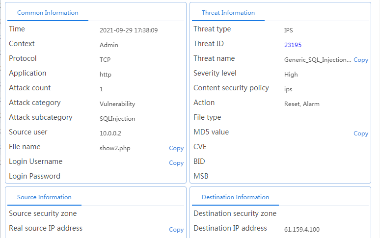
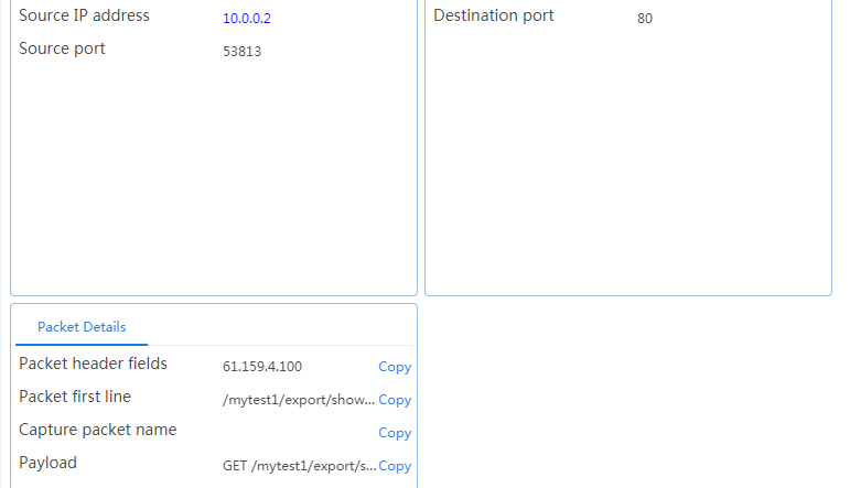
Handling AV attacks
Attack the host, transfer the virus test sample through HTTP to the LB device, and observe the detection result.
To view the threat log, navigate to the Monitor > Device Logs > Traffic Logs page. Click the Details icon to view the detailed information about the log.
Figure 613 Viewing the threat log
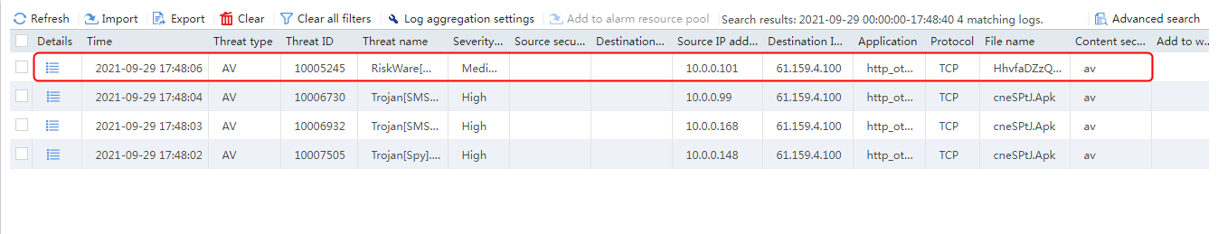
Figure 614 AV threat log details
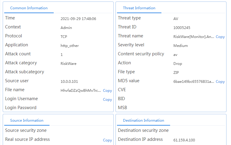
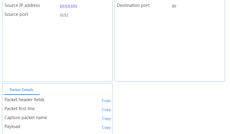
Handling WAF attacks
The host sends a request with the following URL through a browser:
http://61.159.4.100/x.php?id%20=123456%27%3Cscript%3Ealert(%27xss%27)%3C/script%3E
The device can detect the attack traffic, intercept the attack, and generate a threat log.
You can view the threat log on the log server.
Sep 29 17:48:41 2021 Sysname %%10 VsysId:1 WAF/4/WAF_IPV4_INTERZONE: Protocol(1001)=TCP; Application(1002)=http; SrcIPAddr(1003)=10.0.0.2; SrcPort(1004)=51300; DstIPAddr(1007)=61.159.4.100; DstPort(1008)=80; RcvVPNInstance(1042)=; SrcZoneName(1025)=--; DstZoneName(1035)=--; UserName(1113)=10.0.0.2; PolicyName(1079)=waf; AttackName(1088)=Generic_Cross_Site_Scripting_Attempt_Base_On_Message_Dialogs(HttpURI); AttackID(1089)=24485; Category(1090)=Vulnerability; Protection(1091)=WebApplication; SubProtection(1092)=Any; Severity(1087)=MEDIUM; Action(1053)=Reset & Logging; CVE(1075)=--; BID(1076)=--; MSB(1077)=--; HitDirection(1115)=original; RealSrcIP(1100)=; SubCategory(1124)=XSS; CapturePktName(1116)=; SrcMacAddr(1021)=000c-294d-297a; DstMacAddr(1022)=0c3a-fa8c-cce8; HttpHost(1117)= 61.159.4.100; HttpUserAgent(1210)= Mozilla/4.0 (compatible; MSIE 8.0; Windows NT 6.1; WOW64; Trident/4.0; SLCC2; .NET CLR 2.0.50727; .NET CLR 3.5.30729; .NET CLR; URL(1093)= 61.159.4.100/x.php?id%20=123456%27%3Cscript%3Ealert(%2
Configuration files
#
nqa template tcp t1
destination port 80
#
customlog format dpi waf
customlog host 188.100.0.112 export dpi waf
#
app-profile vs1632905761_vs
ips apply policy ips mode protect
anti-virus apply policy av mode protect
waf apply policy waf mode protect
#
inspect logging parameter-profile av_logging_default_parameter
#
inspect logging parameter-profile ips_logging_default_parameter
#
server-farm sf1
predictor hash address source
probe t1
success-criteria at-least 1
real-server rs1 port 0
success-criteria at-least 1
real-server rs2 port 0
success-criteria at-least 1
real-server rs3 port 0
success-criteria at-least 1
#
real-server rs1
ip address 192.168.1.1
#
real-server rs2
ip address 192.168.1.2
#
real-server rs3
ip address 192.168.1.3
#
virtual-server vs type tcp
virtual ip address 61.159.4.100
default server-farm sf1
connection-sync enable
sticky-sync enable global
dpi-app-profile vs1632905761_vs
service enable
#
waf policy waf
#
dac log-collect service dpi threat enable
#
ips policy ips
status enabled
#
ips logging parameter-profile ips_logging_default_parameter
#
anti-virus policy av
#
anti-virus logging parameter-profile av_logging_default_parameter
#