- Table of Contents
- Related Documents
-
| Title | Size | Download |
|---|---|---|
| 03-Multi-Service Egress Gateway Configuration Examples | 2.80 MB |
Multi-Service Egress Gateway Configuration Examples
Copyright © 2022 New H3C Technologies Co., Ltd. All rights reserved.
No part of this manual may be reproduced or transmitted in any form or by any means without prior written consent of New H3C Technologies Co., Ltd.
Except for the trademarks of New H3C Technologies Co., Ltd., any trademarks that may be mentioned in this document are the property of their respective owners.
The information in this document is subject to change without notice.
Contents
Example: Configuring a multi-service egress gateway
Assigning IP addresses to interfaces
Configuring link load balancing
Creating a NAT address group and applying it to the link outgoing interface
Configuring transparent DNS proxy
Verifying link load balancing access
Transparent DNS proxy access and verification results
NAT server verification results
NAT hairpin verification results
Intelligent DNS verification results
Introduction
The following information provides examples of multi-service configurations on the load balancing (LB) device that acts as an egress gateway.
Load balancing is a cluster technology that distributes services among multiple network devices or links.
LB includes the following types:
· Server load balancing—Data centers generally use server load balancing for networking. Network services are distributed to multiple servers or firewalls to enhance the processing capabilities of the servers or firewalls.
· Link load balancing—Link load balancing applies to a network environment where there are multiple carrier links to implement dynamic link selection. This enhances link utilization.
· Transparent DNS proxy—Load balances DNS requests among the links from the internal network to the external network.
· Intelligent DNS—The LB device acts as the authoritative DNS server to process DNS requests from extranet users and select the best link for extranet users if multiple links exist.
Prerequisites
The following information applies to Comware 7-based LB devices. Procedures and information in the examples might be slightly different depending on the software or hardware version of the device.
The configuration examples were created and verified in a lab environment, and all the devices were started with the factory default configuration. When you are working on a live network, make sure you understand the potential impact of every command on your network.
The following information is provided based on the assumption that you have basic knowledge of load balancing (LB).
Example: Configuring a multi-service egress gateway
Network configuration
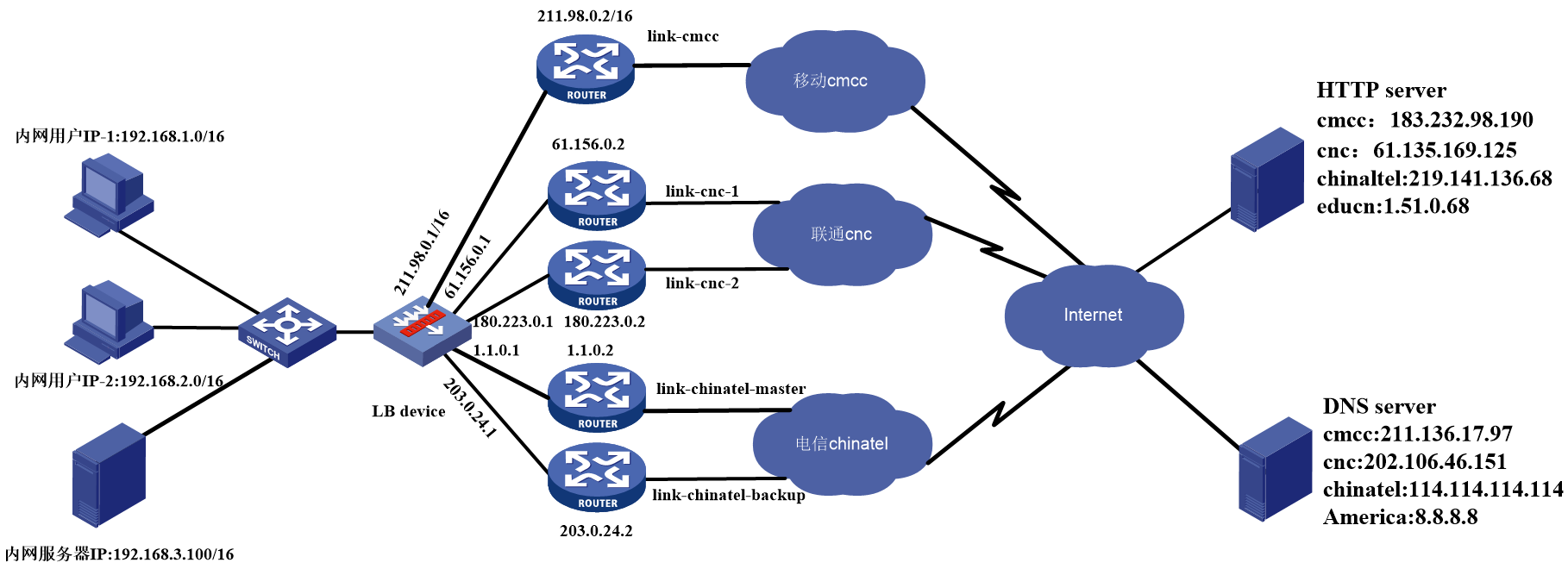
As shown in Figure 1, the LB device is deployed at the network egress of an enterprise. To improve reliability, the enterprise rents five links from three ISPs (CMCC, CNC, and China Telecom). Configure link load balancing to share traffic on the five links as follows:
· Users whose source address is 192.168.10.0/24 access the public network through the CMCC link. Other users can use all the ISP links, and users of an ISP preferentially use the link of that ISP.
· China Telecom has one primary link with bandwidth of 100 Mbps and a backup link. In addition, the internal network 192.168.0.0/16 is not allowed to be exposed to the extranet.
· For DNS requests from the intranet to the public network, the requests for www.testyoutube.com must be sent to the DNS server 8.8.8.8 for resolution. Other DNS requests are load shared among the DNS servers of different ISPs to avoid traffic congestion on a certain link.
· Configure link load balancing and transparent DNS proxy for the CMCC link designated for users whose source address is 192.168.10.0/24.
· To enable external users to access a domain name, configure inbound link load balancing for intelligent DNS resolution to select the optimal domain address for the client through ISP.
· Deploy a server on the intranet so that external users can access the internal server.
· The DNS server is deployed on the public network. To enable intranet users to access the internal Web server through the domain name, you need to allow the intranet users to access the internal Web server by its IP address.
Analysis
1. Analysis on the configuration for link load balancing:
¡ Configure a load balancing policy to direct traffic from certain users to the CMCC link.
¡ Configure a load balancing policy to determine which ISPs the destination addresses of intranet users belong to, and select the corresponding the ISP links for the traffic.
¡ If a link is disconnected, an outbound link can be selected by matching the configured load balancing policy based on the health monitoring status.
¡ If a destination address is not within the configured ISP, an outbound link will be selected by matching the default load balancing policy, or the traffic will be forwarded based on routing configuration.
2. Analysis on the link protection configuration for link load balancing
The device calculates whether the link reaches the maximum bandwidth limit * percentage according to the interface bandwidth, which can be configured in the link. Link protection supports switching among different links within the same link group and switching among different link groups. China Telecom in this network has two outbound links, one of which has a bandwidth limit of 100 Mbps and requires link protection. If the priority of the primary link chinatel-master is configured higher, the link will be used preferentially by traffic, for example:
¡ Configure the link group of China Telecom (chinatel) to contain two outbound links: chinatel-master and chinatel-backup. Configure link protection for chinatel-master and a higher priority for chinatel-master than that for chinatel-backup. If chinatel-master is not busy, traffic will be sent only to chinatel-master. If chinatel-master is busy, the traffic will be sent to chinatel-backup. This example describes the configuration in detail.
¡ For protection for links of different ISPs, this example describes the following situation: The two links in the chinatel link group are both busy, so the traffic is switched to the link in the default link group.
3. Analysis on the transparent DNS proxy configuration
¡ According to network requirements, configure domain name www.testyoutube.com and use specific outbound links and DNS server for resolution.
¡ Use CMCC and specific DNS servers to process DNS domain name requests from specific users (certain users who select links based on the source address in link load balancing must select the same links).
¡ If there are no special requirements, load can be shared based on algorithms and DNS requests.
4. Analysis on the NAT hairpin configuration
When the DNS server is deployed on the public network, if one domain name corresponds with multiple IPs, and the intranet user wants to access the Web server of the intranet through the domain name, the DNS server will send a response message to the intranet user containing the public network address of the intranet server. The address resolved by the intranet user DNS is the public network address, and then the user can be granted access by accessing the public network address of the server. The NAT simultaneously translates the source and destination IP addresses of the packets accessing the intranet server at the internal network interface. The destination IP address is translated by matching the internal server configuration on a certain external interface, and the source address is translated by matching the outbound dynamic or static NAT policy on the interface where the internal server is located.
5. Analysis on the intelligent DNS configuration
¡ The local DNS server of the external user initiates a DNS request to the device, and the inbound link load balancing selects the virtual server of the corresponding ISP's links according to the static proximity method.
¡ The outgoing interface is enabled with last hop holding, so as to ensure the requests initiated by the external users and the responses go through the same link.
Software versions used
This configuration example was created and verified on Alpha 1160P16 of L1000-AK325.
Restrictions and guidelines
When you configure the multi-service egress gateway, follow these restrictions and guidelines:
· If intelligent DNS is used for resolution only, follow the configuration provided in this document. If intelligent DNS will be used for server load balancing, refer to the application load balancing configuration example.
· NAT hairpin in this version needs to work with the internal server (NAT server), outbound dynamic address translation, or outbound static address translation. The interfaces where these configurations are located must be on the same interface module. Otherwise the NAT hairpin cannot work correctly.
· When the transparent DNS proxy is used, the intranet client must not configure the DNS server address as the LB device interface address, the address in the same network segment, or the virtual service address. Configure an address that does not exist on the LB device and ensure routing to the LB device.
· When both link load balancing and transparent DNS proxy are enabled, if link load balancing has a source address based traffic class, make sure the transparent DNS proxy selects the same ISP link for the traffic class based on that source address. This can avoid large delay caused by inter-ISP access.
· If the public network address of the internal server (nat server) is an interface address or subaddress, another routing policy should be configured. In this routing policy, set the forwarding mode for the private network address corresponding to the public network address as forwarding, that is, the traffic class for the routing policy is based on the destination address (the private network address), select this traffic class in the routing policy and select forwarding mode as forwarding. This routing policy should take precedence over other routing policies.
· The ISP file is provided with the system by default.
Procedures
Assigning IP addresses to interfaces
Details not shown.
Configuring link load balancing
Configuring health monitoring
1. Navigate to the LB > Global Configuration > Health Monitoring page.
2. Click Create, configure the parameters, and then click OK to add a health monitoring template.
3. Repeat the previous steps to add more health monitoring templates.
This example creates five health monitoring templates, as shown in the following figures:
Figure 2 Creating health monitoring template icmp-cmcc of the ICMP type
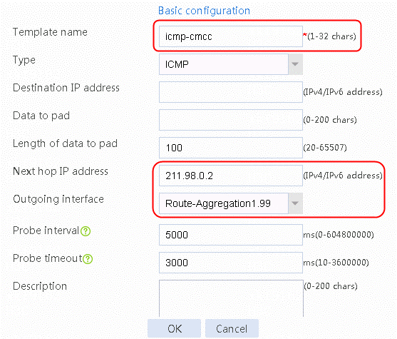
Figure 3 Creating health monitoring template icmp-cnc-1 of the ICMP type
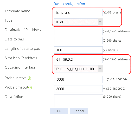
Figure 4 Creating health monitoring template icmp-cnc-2 of the ICMP type
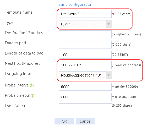
Figure 5 Creating health monitoring template icmp-chinatel-master of the ICMP type
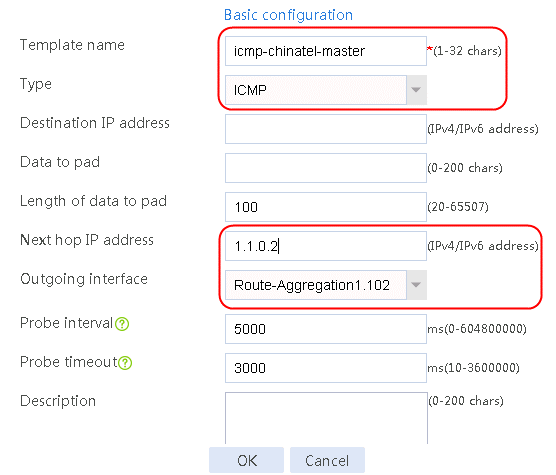
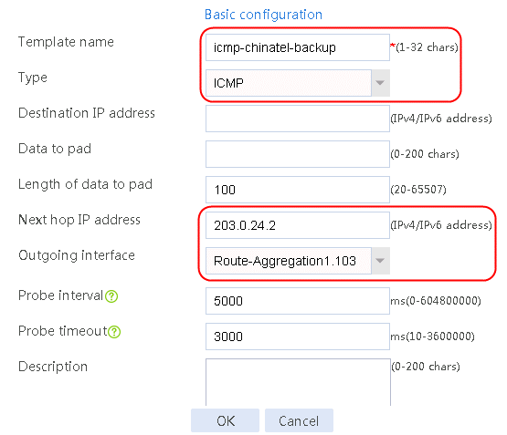
Figure 6 Creating health monitoring template icmp-chinatel-backup of the ICMP type
|
|
WARNING! The health monitoring templates each require an outgoing interface to check the corresponding links. If you do not specify an outgoing interface, a health monitoring detection that would fail might be successful because of an equal-cost route. |
Configuring link groups
1. Navigate to the LB > Link Load Balancing > Out Link Load Balancing > Link Group page.
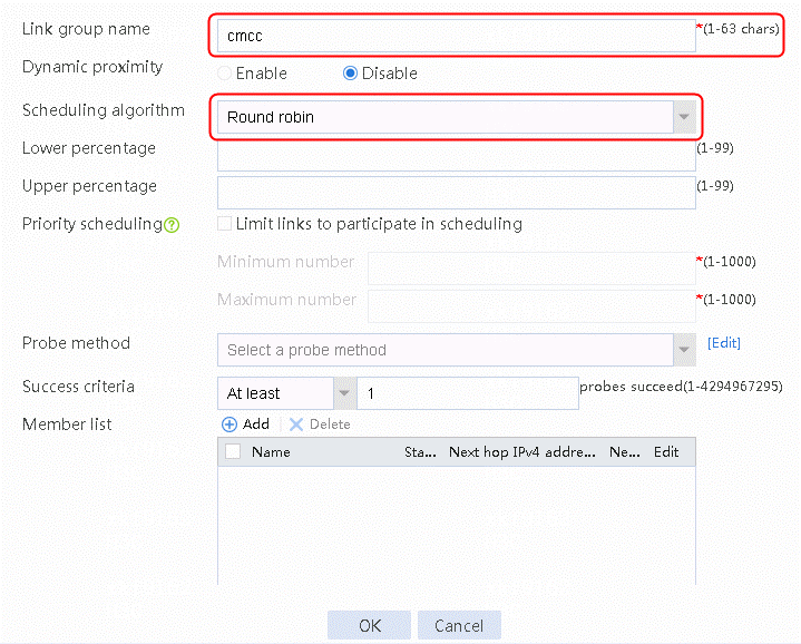
2. Click Create. Configure the link group name as cmcc, and the scheduling algorithm as weighted round robin, as shown in the following figure:
Figure 7 Creating link group lg-cnc
3. Click OK.
4. Create link groups cnc, chinatel, and default in the same way link group cmcc is created.
Creating links
1. Navigate to the LB > Link Load Balancing > Out Link Load Balancing > Link Group page.
2. Edit the link group cmcc, and click Add to create a member list. Create a link named link-cmcc, configure the next hop IP address as 211.98.0.2, and select health monitoring template icmp-cmcc as the probe method.
Figure 8 Adding a link group member
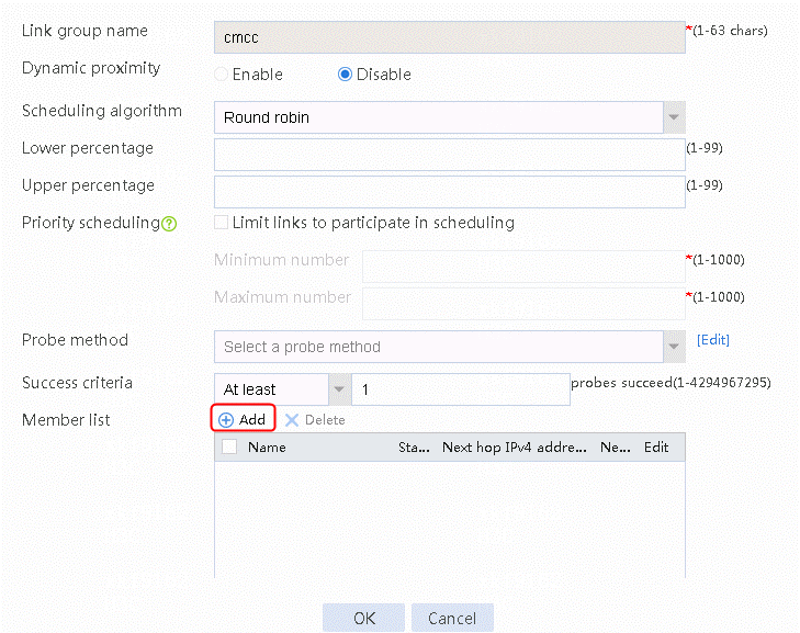
Figure 9 Creating link link-cmcc
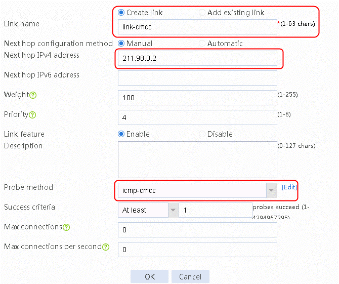
3. Click OK.
Figure 10 Link information
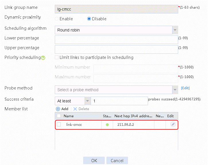
4. Click OK.
5. Create links link-cnc-1, link-cnc-2, link-chinatel-master, and link-chinatel-backup in the same way link link-cmcc is created. Note the following:
¡ Create links link-cnc-1 and link-cnc-2 in link group cnc.
¡ For link link-cnc-1, configure the next hop IP address as 61.156.0.2, and select health monitoring template icmp-cnc-1 as the probe method.
¡ For link link-cnc-2, configure the next hop IP address as 180.223.0.2, and select health monitoring template icmp-cnc-2 as the probe method.
¡ Create links link-chinatel-master and link-chinatel-backup in link group chinatel.
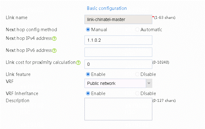
¡ For link link-chinatel-master, configure the next hop IP address as 1.1.0.2, set the priority level to 8, and select health monitoring template icmp-chinatel-master as the probe method.
¡ For link link-chinatel-backup, configure the next hop IP address as 203.0.24.2, set the priority level to 4, and select health monitoring template icmp-chinatel-backup as the probe method.
6. Create default links:
a. Navigate to the LB > Link Load Balancing > Out Link Load Balancing > Link Group.
b. Edit link group default.
c. Click Add. Select Add existing link to add link link-cmcc, select health monitoring template icmp-cmcc as the probe method, and then click OK.
d. Repeat the previous step to add links link-cnc-1, link-cnc-2, link-chinatel-master, and link-chinatel-backup, with the probe method being health monitoring template icmp-cnc-1, icmp-cnc-2, icmp-chinatel-master, and icmp-chinatel-backup, respectively.
Configuring links
1. Navigate to the LB > Global Configuration > Links page.
2. Edit link link-chinatel-master.
3. Set the bandwidth ratio to 80%, bandwidth recovery ratio to 70%, and expected bandwidth to 12500 Kbps.
Figure 11 Editing link link-chinatel-master
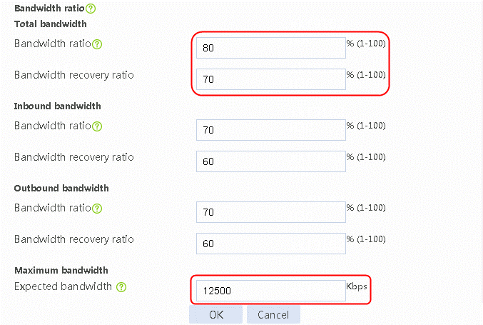
4. Click OK.
Configuring traffic class
1. Navigate to the LB > Link Load Balancing > Out Link Load Balancing > Class page。
2. Click Create.
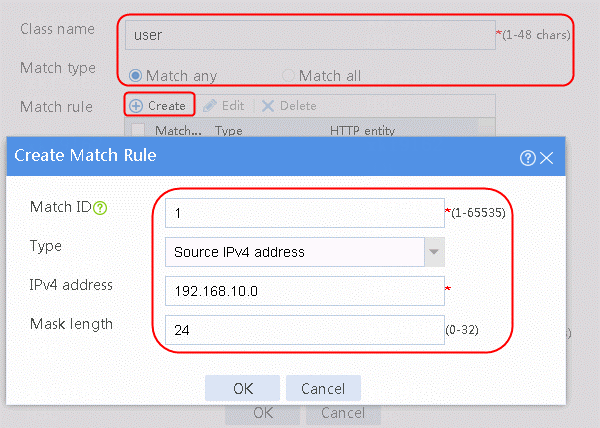
3. Configure the class name as user.
4. Click Match any and then click Create to create a match rule.
5. Set Match ID to 1 and Type to Source IPv4 address. Configure the HTTP entity as 192.168.10.0/24.
Figure 12 Creating traffic class
6. Click OK.
Figure 13 Traffic class information
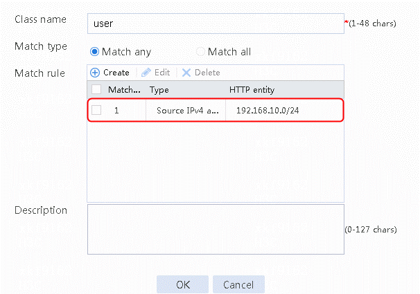
7. Click OK.
8. Create traffic classes cmcc, chinatel, and cnc in the same way you created class user. Note the following:
¡ In the match rule for class cmcc, configure Type as ISP and the HTTP entity as cmcc.
¡ In the match rule for class chinatel, configure Type as ISP and the HTTP entity as chinatel.
¡ In the match rule for class cnc, configure Type as ISP and the HTTP entity as cnc.
Configuring load balancing policy
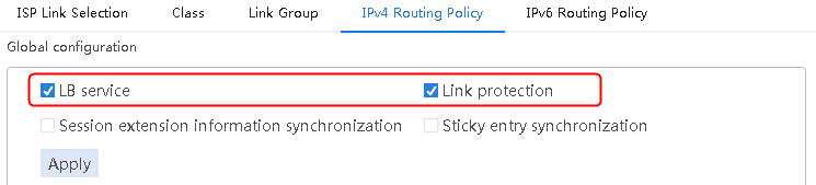
1. Navigate to the LB > Link Load Balancing > Out Link Load Balancing > IPv4 Routing Policy page.
2. Select LB service and Link protection in the Global configuration area.
3. Click Apply.
Figure 14 Enabling load balancing
4. Navigate to the LB > Link Load Balancing > Out Link Load Balancing > IPv4 Routing Policy page
5. Click Create to create IPv4 routing policy 1.
6. Select user for Class, Load balance for Forwarding mode, cmcc for Primary link group, Match next rule for Fallback action, and Match next rule for All links are busy.
Figure 15 Configuring IPv4 routing policy 1
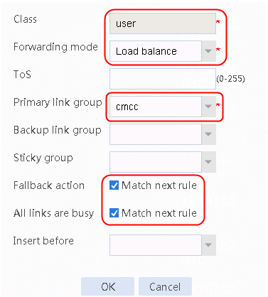
7. Click OK.
8. Create other IPv4 routing policies in the same way as policy 1 is created.
¡ Create IPv4 routing policy 2: Select cmcc for Class, Load balance for Forwarding mode, cmcc for Primary link group, Match next rule for Fallback action, and Match next rule for All links are busy.
¡ Create IPv4 routing policy 3: Select cnc for Class, Load balance for Forwarding mode, cnc for Primary link group, Match next rule for Fallback action, and Match next rule for All links are busy.
¡ Create IPv4 routing policy 4: Select chinatel for Class, Load balance for Forwarding mode, chinatel for Primary link group, Match next rule for Fallback action, and Match next rule for All links are busy.
¡ Create a default routing policy: Select Default for Class, Load balance for Forwarding mode, and default for Primary link group, so that packets that cannot match the traffic class are sent to the default link group.
Enabling link protection logging (LB link busy state logging)
This feature is not configurable in Web interface. Configure this feature in CLI as follows:
<Sysname>system-view
System View: return to User View with Ctrl+Z.
[Sysname]loadbalance log enable bandwidth-busy
Creating a NAT address group and applying it to the link outgoing interface
1. Navigate to the Objects > Object Groups > NAT Address Groups page.
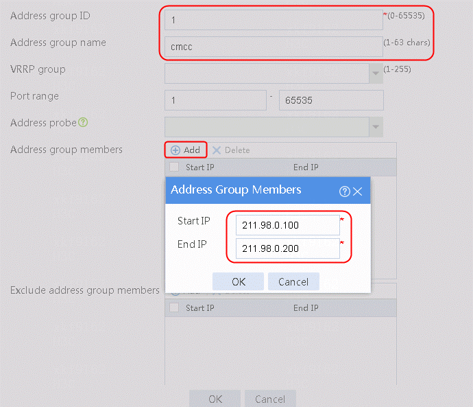
2. Click Create, and set Address group ID to 1 and Address group name to cnc.
3. Click Add and set Start IP and End IP under Address Group Members to 61.156.0.100 and 61.156.0.200 respectively, as shown in the following figure.
Figure 16 Creating address group 1
4. Click OK.
Figure 17 Information of address group 1
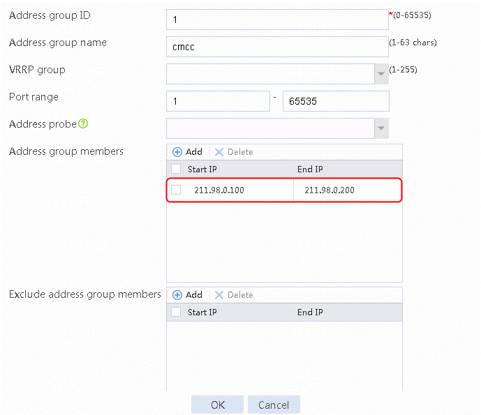
5. Click OK.
6. Create the address groups 2, 3, 4, and 5 in the same way group 1 is configured.
¡ Navigate to the Objects > Object Groups > NAT Address Groups page. Click Create, and set Address group ID to 2 and Address group name to cnc-1. Click Add and set Start IP and End IP for Address Group Members to 61.156.0.100 and 61.156.0.200 respectively.
¡ Navigate to the Objects > Object Groups > NAT Address Groups page. Click Create to set Address group ID to 3 and Address group name to cnc-2. Click Add and set Start IP and End IP for Address Group Members to 180.223.0.100 and 180.223.0.200 respectively.
¡ Navigate to the Objects > Object Groups > NAT Address Groups page. Click Create and set Address group ID to 4 and Address group name to chinatel-master. Click Add and set Start IP and End IP for Address Group Members to 1.1.0.100 and 1.1.0.200 respectively.
¡ Navigate to the Objects > Object Groups > NAT Address Groups page. Click Create to set Address group ID to 5 and Address group name to chinatel-backup. Click Add and set Start IP and End IP for Address Group Members to 203.0.24.100 and 203.0.24.200 respectively.
7. Navigate to the Network > NAT > IPv4 > Dynamic NAT page. Click Create to create a dynamic NAT policy (based on ACL). Select the outgoing interface RAGG1.100 that corresponds to the next hop of the link. Select NAT address group 1 for the source address after NAT, as shown in the following figure.
Figure 18 Creating dynamic NAT policy 1
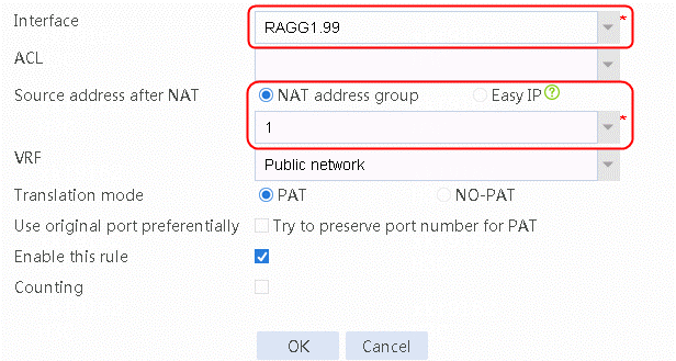
8. Click OK.
9. Create dynamic NAT policies 2, 3, 4, and 5 in the same policy 1 is created. Note the following:
¡ For policy 2: select the corresponding outgoing interface RAGG1.100 of the next hop of the link. Select NAT address group 2 for the source address after NAT.
¡ For policy 3: Select the corresponding outgoing interface RAGG1.101 of the next hop of the link. Select NAT address group 3 for the source address after NAT.
¡ For policy 4: Select the corresponding outgoing interface RAGG1.102 of the next hop of the link. Select NAT address group 4 for the source address after NAT.
¡ For policy 5: Select the corresponding outgoing interface RAGG1.103 of the next hop of the link. Select NAT address group 5 for the source address after NAT.
Configuring transparent DNS proxy
Configuring a DNS server pool
1. Navigate to the LB > Link Load Balancing > DNS Proxy > DNS Server Pool page.
2. Click Create.
3. Set the pool name to dns-pool. Select Bandwidth for Scheduling algorithm.
Figure 19 Creating DNS server pool dns-pool
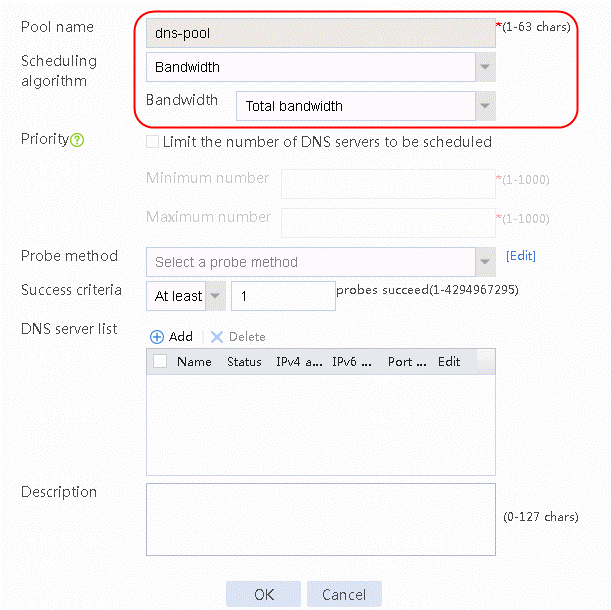
4. Click OK to complete the operation.
5. Creating DNS server pool dns-special in the same way as DNS server pool dns-pool is created.
Configuring a DNS server
1. Navigate to the LB > Link Load Balancing > DNS Proxy > DNS Server Pool page.
2. Edit the DNS server pool dns-pool. Create the DNS server list and set the DNS server name to cmcc, chinatel, and cnc respectively.
Figure 20 Adding a DNS server to the DNS pool dns-pool
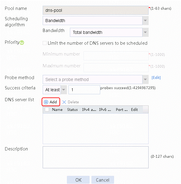
Figure 21 Creating DNS server cmcc
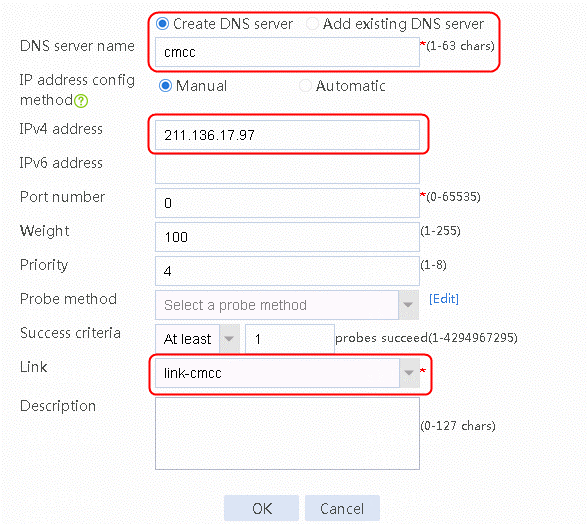
3. Click OK.
Figure 22 Creating DNS server cnc
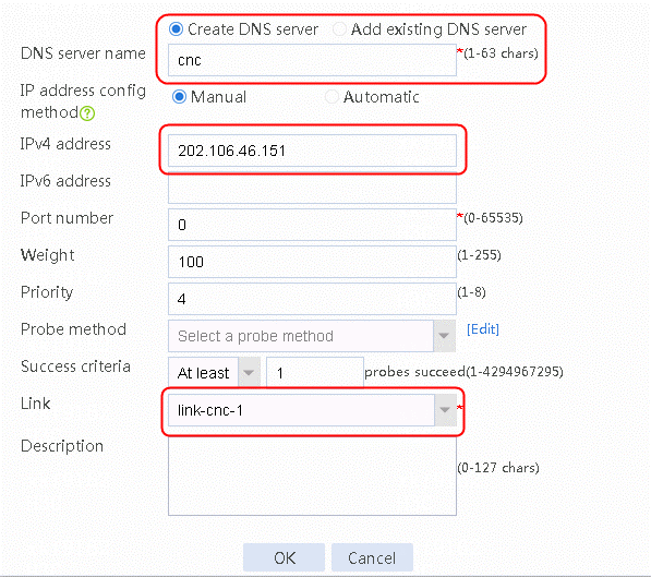
4. Click OK.
Figure 23 Creating DNS server chinatel
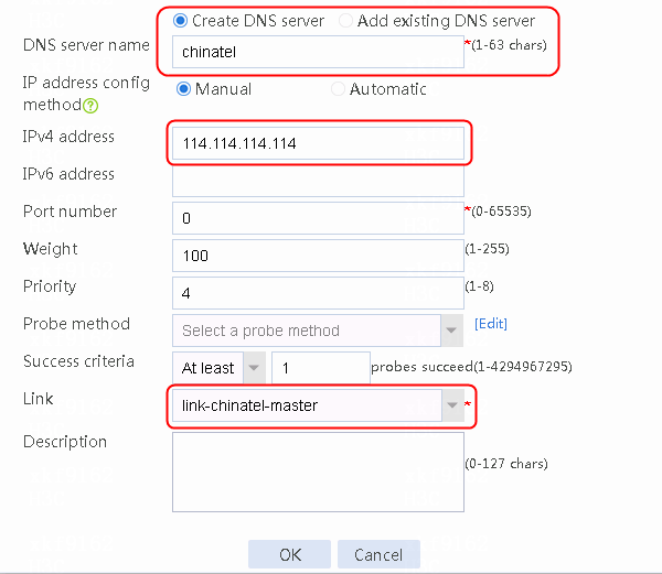
5. Click OK.
Figure 24 DNS server information

6. Click OK.
7. Create the DNS server america:
a. Navigate to the LB > Link Load Balancing > DNS Proxy > DNS Server Pool page.
b. Edit the DNS server pool dns-pool-special.
c. Add a DNS server to the DNS server list: set the DNS server name to america, IPv4 address to 8.8.8.8 and the link to link-cmcc.
Configuring a traffic class
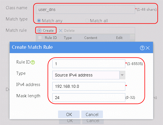
1. Navigate to the LB > Link Load Balancing > DNS Proxy > Class page.
2. Click Create and set the class name to user_dns. Click Match any and Create to create the match rule 1. Set Match ID to 1 and Type to Source IPv4 address. The HTTP entity is 192.168.10.0, as shown in the following figure.
Figure 25 Creating new traffic class user_dns
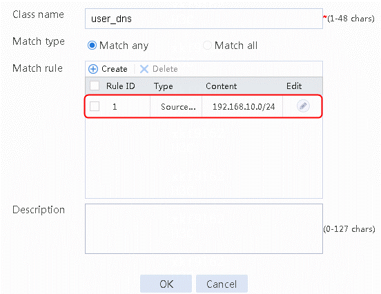
3. Click OK.
Figure 26 Traffic class information
4. Create the class www.testyoutube:
a. Navigate to the LB > Link Load Balancing > DNS Proxy > Class page.
b. Click Create. Configure the class name as www.testyoutube. Click Match any and Create to create the match rule 1. Set Match ID to 1 and select domain name for Type. The HTTP entity is www.testyoutube.com.
Configuring IPv4 proxy policy
1. Navigate to the LB > Link Load Balancing > DNS Proxy > IPv4 Proxy Policy page.
2. Select Transparent DNS proxy and Link protection in the Common Configuration area.
Figure 27 Configuring transparent DNS proxy
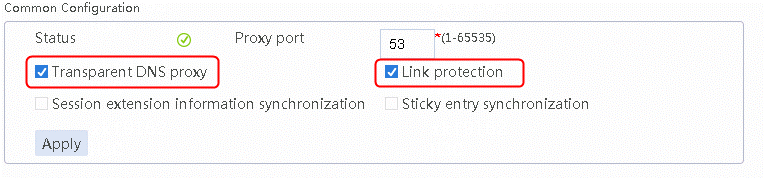
3. Click Apply.
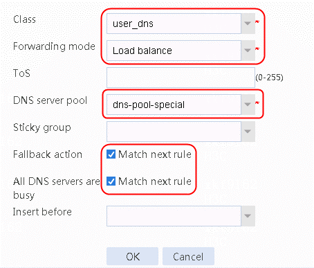
4. Navigate to the LB > Link Load Balancing > DNS Proxy > IPv4 Proxy Policy page, and then click Create to create IPv4 routing policy 1. Select user_dns for Class, Load balance for Forwarding mode, dns-pool-special for DNS server pool, Match next rule for Fallback action, and Match next rule for All DNS servers are busy, as shown in the following figure.
Figure 28 Creating IPv4 proxy policy 1
5. Click OK.
6. Create other proxy policies in the same way proxy policy 1 is created.
¡ Create IPv4 proxy policy 2: Select www.testyoutube for Class, Load balance for Forwarding mode, dns-pool-special for DNS server pool, Match next rule for Fallback action, and Match next rule for All DNS servers are busy.
¡ Create default proxy policy: Select Default for Class, Load balance for Forwarding mode, and dns-pool for DNS server pool.
Configuring a NAT server
Creating a NAT server
1. Navigate to the Network > NAT > IPv4 > NAT Servers > Policy Configuration page. Click Create and then configure NAT server name natserver as follows:
Figure 29 Creating a NAT server
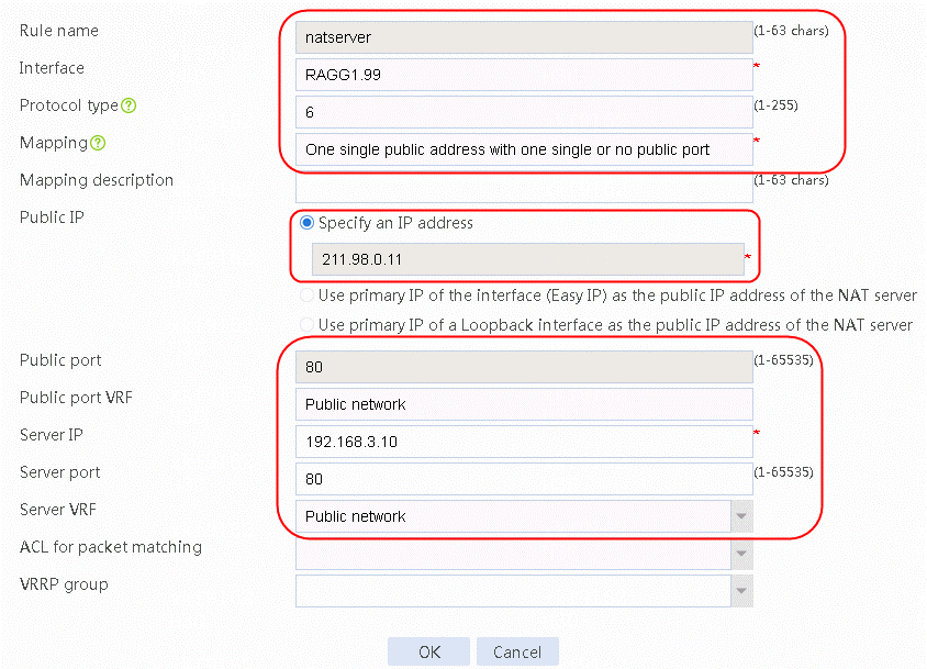
2. Click OK to complete the operation.
Configuring NAT hairpin
Configuring DNS hairpin
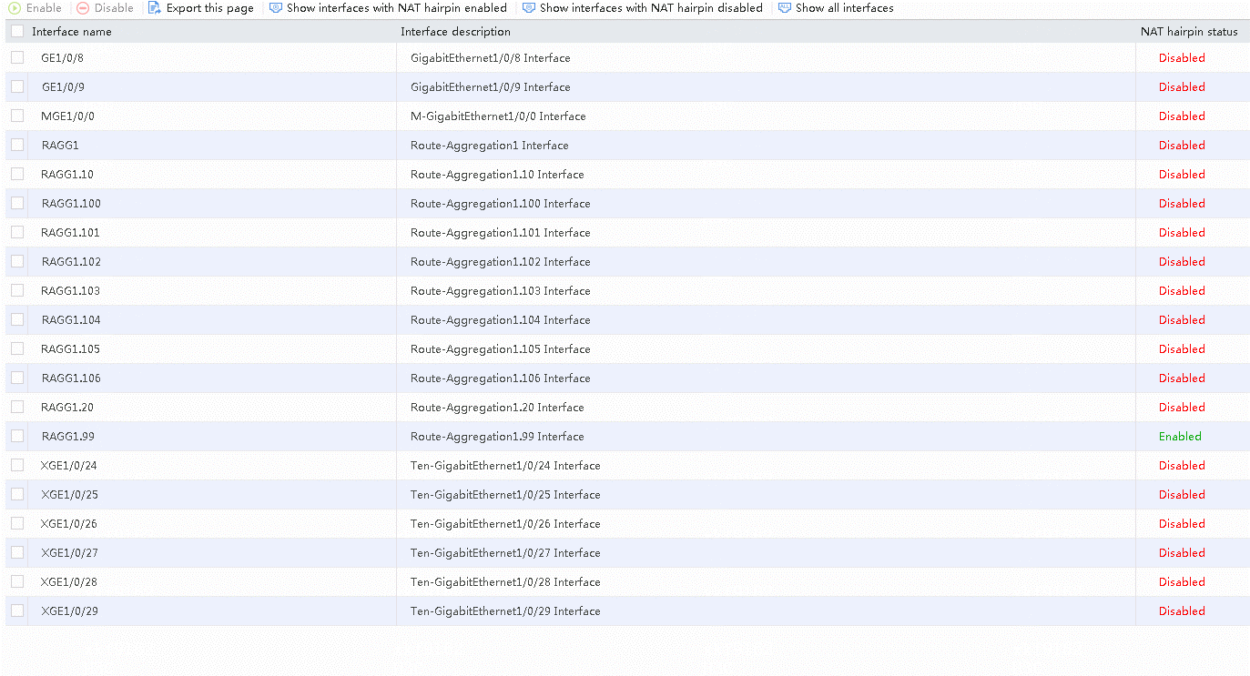
1. Navigate to the Network > NAT > IPv4 > NAT Advanced Settings > NAT Hairpin page.
2. Select the interface and click Enable to enable the NAT hairpin function, as shown in the following figure.
Figure 30 Configuring NAT hairpin
Configuring intelligent DNS
Configuring a virtual server
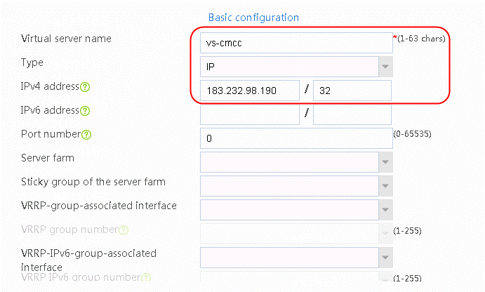
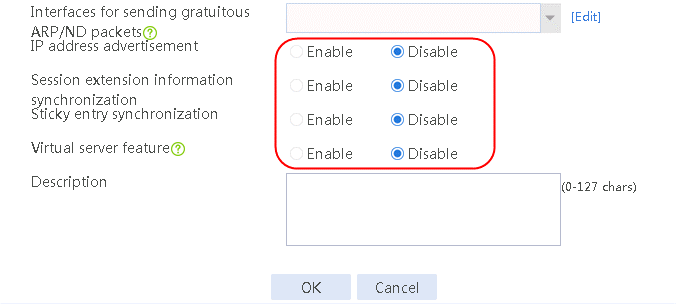
1. Navigate to the LB > Application Load Balancing > Virtual Servers page.
2. Click Create and set the virtual server name to vs-cnc-1, Type to IP, and IPv4 address to 183.232.98.190, as shown in the following figure.
Figure 31 Creating virtual server vs-cnc-1 of IP type
3. Click OK.
4. Create virtual servers vs-cnc-1, vs-cnc-2, vs-chinatel-1 and vs-chinatel-2 in the same way virtual server vs-cmcc is created.
¡ Set the virtual server name to vs-cnc-1, type to IP, and IPv4 address to 140.207.128.140.
¡ Set the virtual server name to vs-cnc-2, type to IP, IPv4 address to 140.207.128.150.
¡ Set the virtual server name to vs-chinatel-1, type to IP, and IPv4 address to 183.2.186.153.
¡ Set the virtual server name to vs-chinatel-2, type to IP, IPv4 address to 183.61.47.15.
Configuring regions
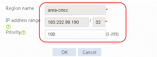
1. Navigate to the LB > Global Configuration > Regions page. Click Create and set the region name to area-cmcc, area-cnc and area-chinatel respectively. Then select and add cmcc, cnc and chinatel respectively for ISP.
Figure 32 Creating region area-cmcc
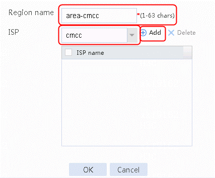
2. Select cmcc for ISP and click Add.
Figure 33 Region area-cmcc configuration page
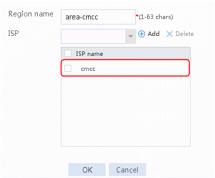
3. Click OK.
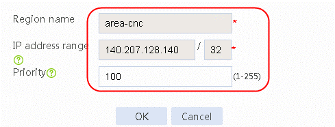
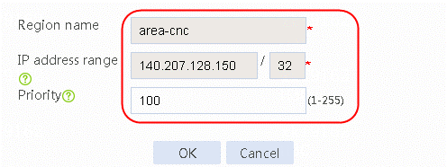
Figure 34 Creating region area-cnc
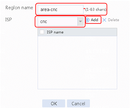
4. Select cnc for ISP and click Add.
Figure 35 Region area-cnc configuration page
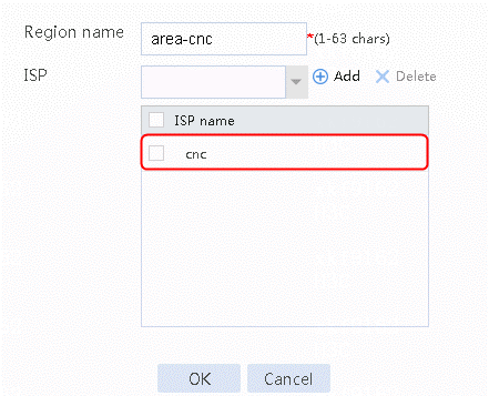
5. Click OK.
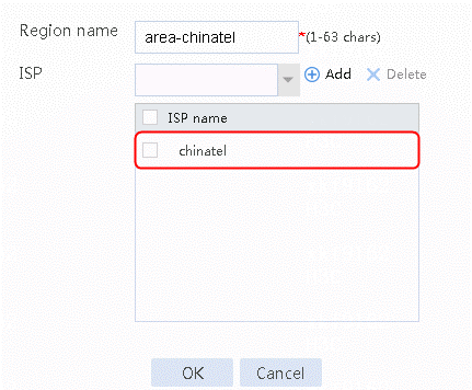
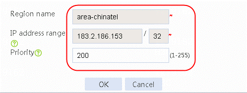
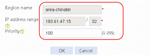
Figure 36 Creating region area-chinatel
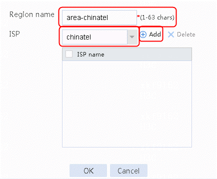
6. Select chinatel for ISP and click Add.
Figure 37 Region area-chinatel configuration page
7. Click OK.
Configuring DNS mapping and virtual IP pools
Please follow the steps below:
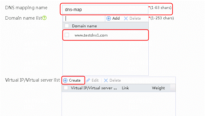
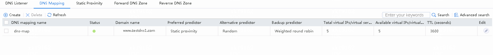
1. Navigate to the LB > Intelligent DNS > Local Intelligent DNS > DNS Mapping page.
2. Click Create and set the DNS mapping name to dns-map, and add domain name www.testdns1.com.
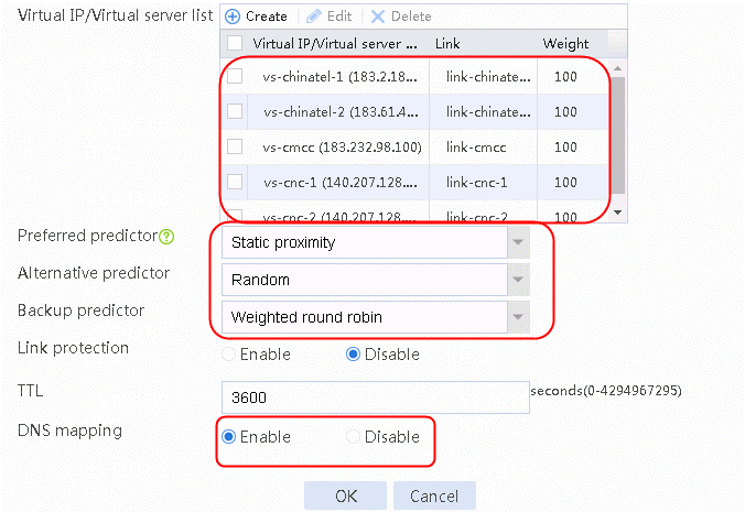
3. Create a virtual IP/virtual server list and select Static proximity for Preferred predictor, Random for Alternative predictor, and Weighted round robin for Backup predictor.
4. Enable the DNS mapping function, as shown in the following figure.
Figure 38 Creating DNS mapping dns-map
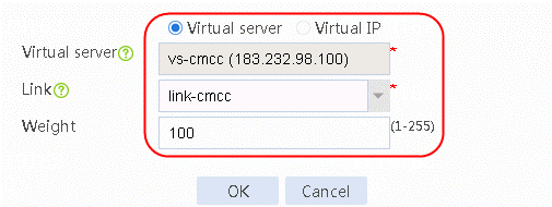
5. Click Create to create a virtual IP/virtual server list. Add virtual server vs-cmcc, select the link link-cmcc and set Weight to 100.
Figure 39 Adding the virtual server vs-cmcc
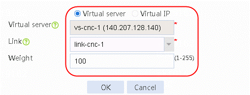
6. Continue to create a virtual IP/virtual server list. Add virtual server vs-cnc-1, select the link link-cnc-1 and set Weight to 100.
Figure 40 Adding the virtual server vs-cnc-1
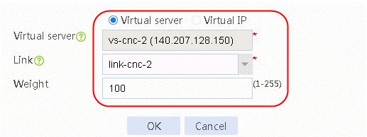
7. Continue to create a virtual IP/virtual server list. Add virtual server vs-cnc-2, select the link link-cnc-2 and set Weight to 100.
Figure 41 Adding the virtual server vs-cnc-2
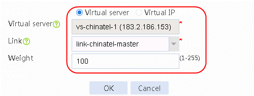
8. Continue to create a virtual IP/virtual server list. Add virtual server vs-chinatel-1, select the link link-chinatel-master and set Weight to 100.
Figure 42 Adding the virtual server vs-chinatel-1
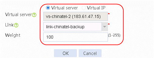
9. Continue to create a virtual IP/virtual server list. Add virtual server vs-chinatel- backup, select the link link-chinatel-backup and set Weight to 100.
Figure 43 Adding the virtual server vs-chinatel- backup
10. View the virtual IP/virtual server list. Configure DNS mapping and select Static proximity for Preferred predictor, Random for Alternative predictor, and Weighted round robin for Backup predictor. Enable the DNS mapping function.
Figure 44 Configuring DNS mapping dns-map
11. Click OK.
Configuring static proximity
1. Navigate to the LB > Intelligent DNS > Local Intelligent DNS > Static Proximity page. Click Create to configure static proximity as follows:
Figure 45 Creating static proximity 1 of area-cmcc
2. Click OK.
Figure 46 Creating static proximity 2 of area-cnc
3. Click OK.
Figure 47 Creating static proximity 1 of area-cnc
4. Click OK.
Figure 48 Creating static proximity 2 of area-chinatel
5. Click OK.
Figure 49 Creating static proximity 2 of area-chinatel
6. Click OK.
Configuring DNS listener
1. Navigate to the LB > Intelligent DNS > Local Intelligent DNS > DNS Listener page.
2. Click Create.
3. Set DNS listener name to listener, IPv4 address to 61.156.0.1 and enable DNS listening, as shown in the following figure.
Figure 50 Creating DNS listener dl-cnc-1
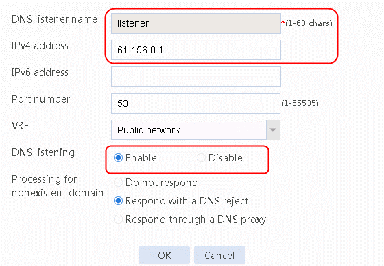
4. Click OK.
Verifying the configuration
Verifying link load balancing access
# Accesses initiated by the intranet client (192.168.10.0/24) will exit through link cmcc.
Navigate to the Monitor > Link Load Balancing > Links > Real-time Statistics page, as shown in the following figure.
Figure 51 Viewing link statistics
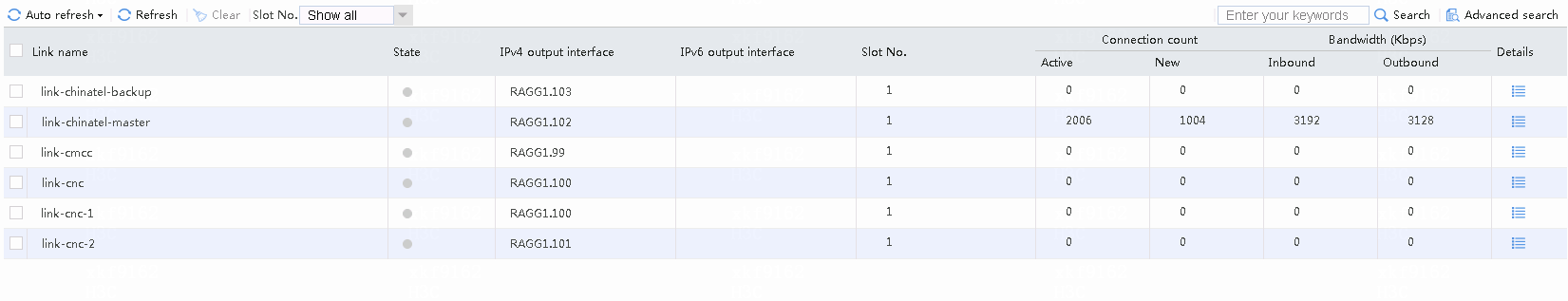
# Accesses destined for CMCC address 183.232.98.190 from internel users (except particular users) use link cmcc.
Navigate to the Monitor > Link Load Balancing > Links > Real-time Statistics page, as shown in the following figure.
Figure 52 Viewing link statistics
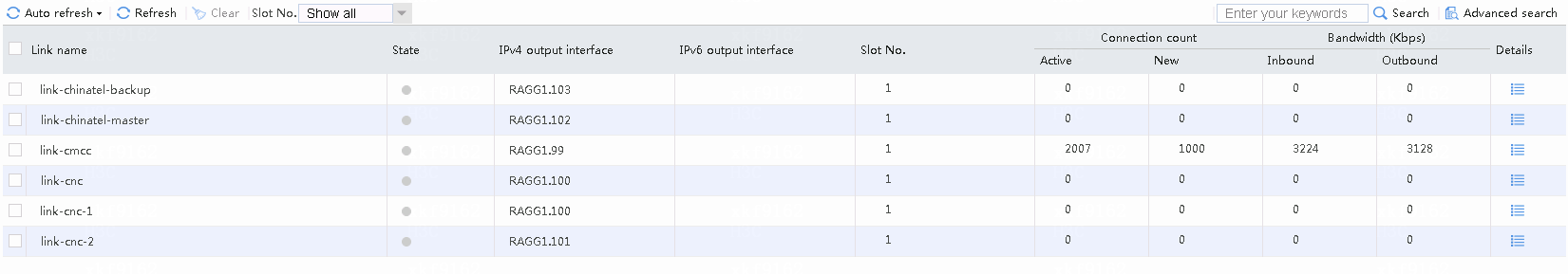
# Accesses destined for CNC address 61.135.169.125 from Internal users (except particular users) use link cnc-1 or cnc-2 with the traffic share ratio at 2:1.
Navigate to the Monitor > Link Load Balancing > Links > Real-time Statistics page, as shown in the following figure.
Figure 53 Viewing link statistics
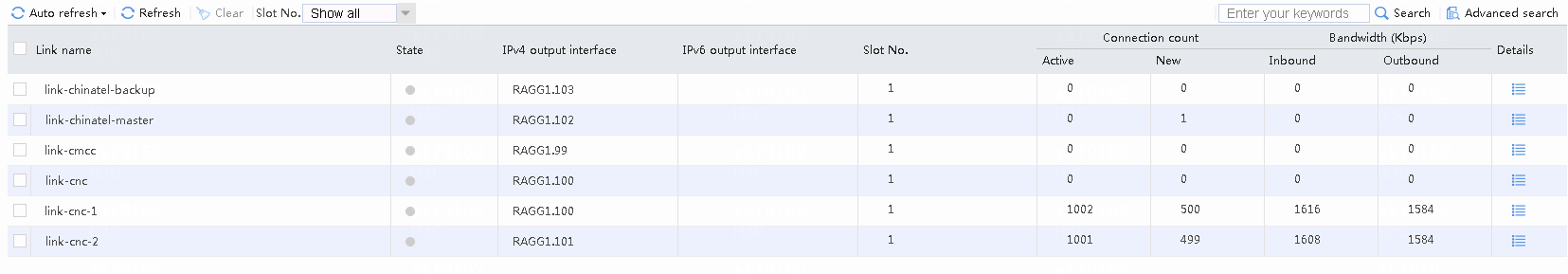
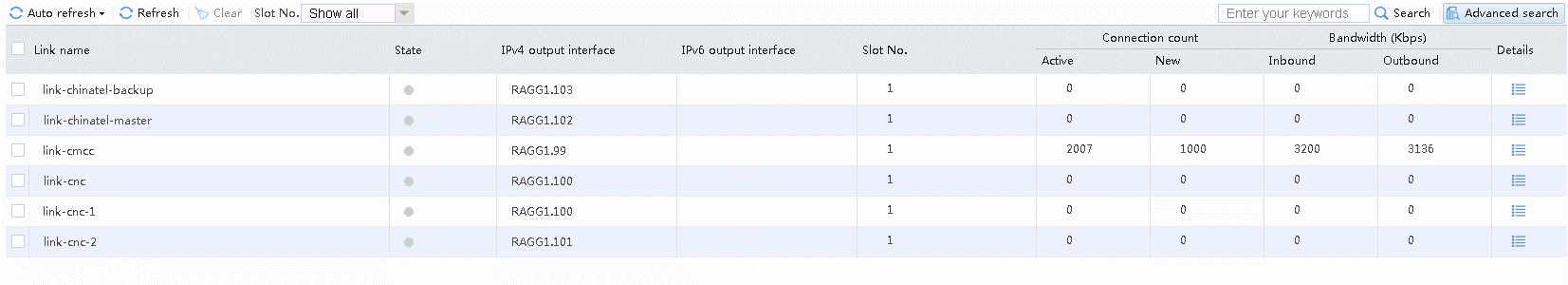
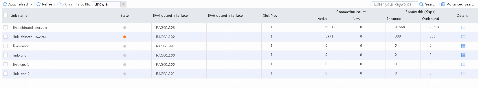
# Accesses destined for China Telecom address 219.141.136.68 from internal users (except particular users) use link chinatel-master instead of the backup link chinatel-backup.
Navigate to the Monitor > Link Load Balancing > Links > Real-time Statistics page, as shown in the following figure.
Figure 54 Viewing link statistics
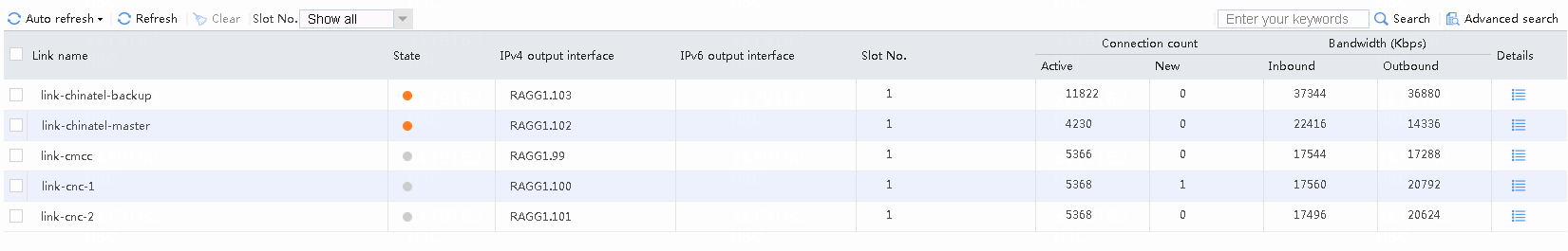
# Internal users (except particular users) initiate access to China Telecom's destination address (chinatel: 219.141.136.68). When occupying 80% of the 100 Mbps bandwidth (that is, 80 Mbps), it will trigger link protection so that the traffic will exit through the backup link chinatel-backup. The link protection log is generated at the same time.
Navigate to the Monitor > Link Load Balancing > Links > Real-time Statistics page, as shown in the following figure.
Figure 55 Viewing link protection
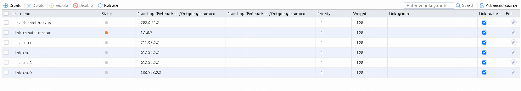
Figure 56 Viewing link statistics
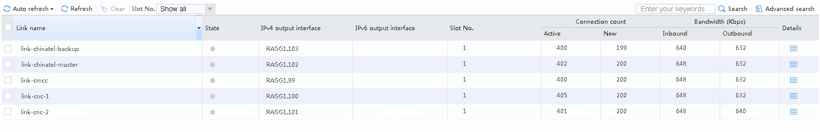
# In the above case, if the bandwidth ratio is configured for chinatel-backup, and both link chinatel-master and link chinatel-backup become busy, the traffic will be switched to the default link group. Because the default link group contains links from various ISPs, traffic will be distributed among these links.
Figure 57 Viewing link statistics
# The internal users (except particular users) initiate access to education website's destination address (educn: 1.51.0.68). As it does not belong to China Mobile, China Unicom or China Telecom, the traffic will exit through the default link group. Because the default link group contains links from various ISPs, traffic will be split among these links.
Figure 58 Viewing link statistics
Transparent DNS proxy access and verification results
# The access initiated by the intranet client (192.168.10.0/24)will exit through link cmcc. DNS server 8.8.8.8 will be selected to perform resolution.
Figure 59 Figure 3-95 Viewing DNS server statistics

# The intranet client (other than particular users) initiates access to DNS domain name at www.testyoutube.com. DNS server address can be any address 11.11.11.11, as long as the device can be routed. We can see that the domain name is sent to the DNS server 8.8.8.8 for resolution.
Figure 60 Viewing DNS server statistics
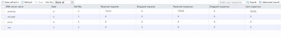
# Multiple intranet clients (other than particular users) initiate access to DNS domain name at www.example1.com. DNS server address is 11.11.11.11, as long as the device can be routed. We can see that the domain name request has been sent to China Mobile and China Unicom. However, no request has been sent to China Telecom because the maximum bandwidth limit is configured at the link at 100 Mbps, which is calculated based on the maximum remaining bandwidth and weight.
Figure 61 Viewing DNS server statistics

NAT server verification results
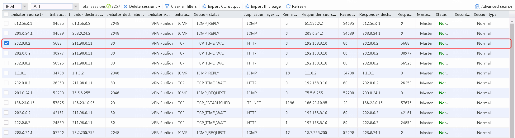
The extranet client initiates a request http://211.98.0.11. The address translation succeeds and the access succeeds.
Figure 62 Viewing the session list
NAT hairpin verification results
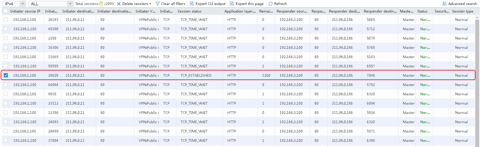
The intranet client initiates a request http://211.98.0.11. The address translation succeeds and the access succeeds.
Figure 63 Viewing the session list
Intelligent DNS verification results
View the status of virtual servers.
Figure 64 Viewing the status of virtual IP pools
The extranet clients of China Mobile request the DNS server 61.156.0.1 for the domain name www.testdns1.com and the address is resolved to be at 183.232.98.190.
The extranet clients of China Unicom request the DNS server 61.156.0.1 for the domain name www.testdns1.com and the address is resolved to be at 140.207.128.140 or 140.207.128.150. The ratio is 1:1.
The extranet clients of China Telecom request the DNS server 61.156.0.1 for the domain name www.testdns1.com and the address is resolved to be at 1183.2.186.153.
When chinatel-master is disconnected, the extranet clients of China Telecom request the DNS server 61.156.0.1 for the domain name www.testdns1.com and the address is resolved to be at 183.61.47.15.
When chinatel-master resumes, extranet clients other than those from three ISPs request the DNS server 61.156.0.1 for the domain name www.testdns1.com and the address may come from one of the following: 183.232.98.190, 140.207.128.140, 140.207.128.150, 1183.2.186.153, and 183.61.47.15.
Configuration files
nat address-group 1 name cmcc
address 211.98.0.100 211.98.0.200
#
nat address-group 2 name cnc-1
address 61.156.0.100 61.156.0.200
#
nat address-group 3 name cnc-2
address 180.223.0.100 180.223.0.200
#
nat address-group 4 name chinatel-master
address 1.1.0.100 1.1.0.200
#
nat address-group 5 name chinatel-backup
address 203.0.24.100 203.0.24.200
#
password-recovery enable
#
vlan 1
#
nqa template icmp icmp
#
nqa template icmp icmp_1
out interface GigabitEthernet2/0/3.100
#
nqa template icmp t1
#
nqa template radius radius
#
interface NULL0
#
interface GigabitEthernet2/0/0
port link-mode route
ip address 186.23.0.97 255.255.0.0
ip address 192.168.0.254 255.255.0.0 sub
nat hairpin enable
#
interface GigabitEthernet2/0/1
port link-mode route
#
interface GigabitEthernet2/0/2
port link-mode route
#
interface GigabitEthernet2/0/3
port link-mode route
#
interface GigabitEthernet2/0/3.100
ip address 211.98.0.1 255.255.255.0
ip last-hop hold
nat outbound address-group 1
nat server protocol tcp global 211.98.0.11 80 inside 192.168.3.100 80
vlan-type dot1q vid 100
#
interface GigabitEthernet2/0/3.101
ip address 61.156.0.1 255.255.255.0
ip last-hop hold
nat outbound address-group 2
vlan-type dot1q vid 101
#
interface GigabitEthernet2/0/3.102
ip address 180.223.0.1 255.255.255.0
ip last-hop hold
nat outbound address-group 3
vlan-type dot1q vid 102
#
interface GigabitEthernet2/0/3.103
ip address 1.1.0.1 255.255.255.0
ip last-hop hold
nat outbound address-group 4
vlan-type dot1q vid 103
#
interface GigabitEthernet2/0/3.104
ip address 203.0.24.1 255.255.255.0
ip last-hop hold
nat outbound address-group 5
vlan-type dot1q vid 104
#
interface GigabitEthernet2/0/3.105
ip address 88.88.88.1 255.255.255.0
ip last-hop hold
vlan-type dot1q vid 105
#
loadbalance link-group chinatel
transparent enable
success-criteria at-least 1
link link-chinatel-backup
success-criteria at-least 1
link link-chinatel-master
priority 8
success-criteria at-least 1
#
loadbalance link-group cmcc
transparent enable
success-criteria at-least 1
link link-cmcc
success-criteria at-least 1
#
loadbalance link-group cnc
transparent enable
success-criteria at-least 1
link link-cnc-1
weight 200
success-criteria at-least 1
link link-cnc-2
success-criteria at-least 1
#
loadbalance link-group default
transparent enable
success-criteria at-least 1
link link-chinatel-backup
success-criteria at-least 1
link link-chinatel-master
success-criteria at-least 1
link link-cmcc
success-criteria at-least 1
link link-cnc-1
success-criteria at-least 1
link link-cnc-2
success-criteria at-least 1
#
loadbalance dns-server-pool dns-pool
predictor bandwidth
success-criteria at-least 1
dns-server chinatel port 0
success-criteria at-least 1
dns-server cmcc port 0
success-criteria at-least 1
dns-server cnc port 0
success-criteria at-least 1
#
loadbalance dns-server-pool dns-pool-special
predictor bandwidth
success-criteria at-least 1
dns-server america port 0
success-criteria at-least 1
#
loadbalance class chinatel type link-generic match-any
match 1 isp chinatel
#
loadbalance class cmcc type link-generic match-any
match 1 isp cmcc
#
loadbalance class cnc type link-generic match-any
match 1 isp cnc
#
loadbalance class user type link-generic match-any
match 1 source ip address 192.168.10.0 24
#
loadbalance class user_dns type dns match-any
match 1 source ip address 192.168.10.0 24
#
loadbalance class www.testyoutube type dns match-any
match 1 domain-name www.testyoutube.com
#
loadbalance action ##defaultactionfordnsproxyipv4##%%autocreatedbyweb%% type dns
dns-server-pool dns-pool
#
loadbalance action ##defaultactionforllbipv4##%%autocreatedbyweb%% type link-gen
eric
link-group default
#
loadbalance action ##defaultactionforllbipv6##%%autocreatedbyweb%% type link-gen
eric
#
loadbalance action dp4#action#for#user_dns type dns
dns-server-pool dns-pool-special
fallback-action continue
busy-action continue
#
loadbalance action dp4#action#for#www.testyoutube type dns
dns-server-pool dns-pool-special
fallback-action continue
busy-action continue
#
loadbalance action ob$action$#for#chinatel type link-generic
link-group chinatel
fallback-action continue
busy-action continue
#
loadbalance action ob$action$#for#cmcc type link-generic
link-group cmcc
fallback-action continue
busy-action continue
#
loadbalance action ob$action$#for#cnc type link-generic
link-group cnc
fallback-action continue
busy-action continue
#
loadbalance action ob$action$#for#user type link-generic
link-group cmcc
fallback-action continue
busy-action continue
#
loadbalance action ob$actionipv6$sunpeng_6 type link-generic
link-group lg_6
#
loadbalance policy ##defaultpolicyfordnsproxyipv4##%%autocreatedbyweb%% type dns
class user_dns action dp4#action#for#user_dns
class www.testyoutube action dp4#action#for#www.testyoutube
default-class action ##defaultactionfordnsproxyipv4##%%autocreatedbyweb%%
#
loadbalance policy ##defaultpolicyforllbipv4##%%autocreatedbyweb%% type link-gen
eric
class user action ob$action$#for#user
class cmcc action ob$action$#for#cmcc
class cnc action ob$action$#for#cnc
class chinatel action ob$action$#for#chinatel
default-class action ##defaultactionforllbipv4##%%autocreatedbyweb%%
#
loadbalance policy ##defaultpolicyforllbipv6##%%autocreatedbyweb%% type link-gen
eric
class sunpeng_6 action ob$actionipv6$sunpeng_6
default-class action ##defaultactionforllbipv6##%%autocreatedbyweb%%
#
virtual-server ##defaultvsforllbipv4##%%autocreatedbyweb%% type link-ip
virtual ip address 0.0.0.0 0
lb-policy ##defaultpolicyforllbipv4##%%autocreatedbyweb%%
bandwidth busy-protection enable
bandwidth interface statistics enable
service enable
#
virtual-server ##defaultvsforllbipv6##%%autocreatedbyweb%% type link-ip
virtual ipv6 address :: 0
lb-policy ##defaultpolicyforllbipv6##%%autocreatedbyweb%%
bandwidth interface statistics enable
#
virtual-server vs-chinatel-1 type ip
virtual ip address 183.2.186.153
#
virtual-server vs-chinatel-2 type ip
virtual ip address 183.61.47.15
#
virtual-server vs-cmcc type ip
virtual ip address 183.232.98.190
#
virtual-server vs-cnc-1 type ip
virtual ip address 140.207.128.140
#
virtual-server vs-cnc-2 type ip
virtual ip address 140.207.128.150
#
loadbalance isp name 1
ip address 2.1.1.0 24
#
loadbalance isp file flash:/lbispinfo_v1.5.tp
#
loadbalance region area-chinatel
isp chinatel
#
loadbalance region area-cmcc
isp cmcc
#
loadbalance region area-cnc
isp cnc
#
loadbalance link link-chinatel-backup
router ip 203.0.24.2
success-criteria at-least 1
probe icmp
#
loadbalance link link-chinatel-master
router ip 1.1.0.2
success-criteria at-least 1
probe icmp
#
loadbalance link link-cmcc
router ip 211.98.0.2
success-criteria at-least 1
probe icmp
#
loadbalance link link-cnc-1
router ip 61.156.0.2
success-criteria at-least 1
probe icmp
#
loadbalance link link-cnc-2
router ip 180.223.0.2
success-criteria at-least 1
probe icmp
#
loadbalance virtual-server-pool vs-pool
predictor preferred topology
predictor alternate random
predictor fallback round-robin
virtual-server vs-chinatel-1 link link-chinatel-master
virtual-server vs-chinatel-2 link link-chinatel-backup
virtual-server vs-cmcc link link-cmcc
virtual-server vs-cnc-1 link link-cnc-1
virtual-server vs-cnc-2 link link-cnc-2
#
loadbalance global-virtual-server-pool %$&^%$#^^(*^*$&^
predictor preferred proximity
predictor alternate proximity
predictor fallback first-available
bandwidth busy-protection enable
success-criteria at-least 1
data-center data-center server localhost virtual-ip 10.1.1.1
success-criteria at-least 1
data-center data-center server localhost virtual-ip 10.1.1.2
weight 255
success-criteria at-least 1
data-center data-center server localhost virtual-ip 10.1.1.3
weight 200
success-criteria at-least 1
#
loadbalance dns-map dns-map
domain-name www.testdns1.com
service enable
virtual-server-pool vs-pool
#
loadbalance global-dns-map $#&^%$*&&)_(+)&%^%(&__+()*_&)(*()*)&*%*&%(*)+
domain-name www.a.com
predictor preferred proximity
predictor alternate proximity
predictor fallback round-robin
service enable
global-virtual-server-pool %$&^%$#^^(*^*$&^
#
loadbalance dns-listener listener
ip address 61.156.0.1
service enable
#
loadbalance log enable bandwidth-busy
#
topology region area-chinatel ip 183.61.47.15
topology region area-chinatel ip 183.2.186.153 priority 200
topology region area-cmcc ip 183.232.98.190
topology region area-cnc ip 140.207.128.140
topology region area-cnc ip 140.207.128.150
#
loadbalance dns-server america
ip address 8.8.8.8
link link-cmcc
success-criteria at-least 1
#
loadbalance dns-server chinatel
ip address 114.114.114.114
link link-chinatel-master
success-criteria at-least 1
#
loadbalance dns-server cmcc
ip address 211.136.17.97
link link-cmcc
success-criteria at-least 1
#
loadbalance dns-server cnc
ip address 202.106.46.151
link link-cnc-1
success-criteria at-least 1
#
loadbalance global-zone a.com
record cname alias www canonical host
#
loadbalance data-center data-center
service enable
link link1
server localhost
member vs_mysql
service enable
#
loadbalance default-syncgroup member (**&%* type local
ip address 8.8.103.1
service enable
#
loadbalance global-dns-listener 1
ip address 8.8.102.1
service enable
#
loadbalance dns-proxy ##defaultdpfordnsproxyipv4##%%autocreatedbyweb%% type udp
ip address 0.0.0.0 0
service enable
lb-policy ##defaultpolicyfordnsproxyipv4##%%autocreatedbyweb%%
bandwidth busy-protection enable
#
return