- Table of Contents
-
- 07-Layer 3—IP Services Configuration Guide
- 00-Preface
- 01-ARP configuration
- 02-IP addressing configuration
- 03-DHCP configuration
- 04-DNS configuration
- 05-NAT configuration
- 06-NAT66 configuration
- 07-IP forwarding basics configuration
- 08-Fast forwarding configuration
- 09-Multi-CPU packet distribution configuration
- 10-Adjacency table configuration
- 11-IRDP configuration
- 12-IP performance optimization configuration
- 13-UDP helper configuration
- 14-IPv6 basics configuration
- 15-DHCPv6 configuration
- 16-IPv6 fast forwarding configuration
- 17-AFT configuration
- 18-Tunneling configuration
- 19-GRE configuration
- 20-ADVPN configuration
- 21-WAAS configuration
- 22-Lighttpd service configuration
- 23-Web caching configuration
- Related Documents
-
| Title | Size | Download |
|---|---|---|
| 19-GRE configuration | 505.35 KB |
Contents
GRE tunnel operating principle
Restrictions and guidelines: GRE configuration
Enabling dropping IPv6 packets that use IPv4-compatible IPv6 addresses
Display and maintenance commands for GRE
Example: Configuring an IPv4 over IPv4 GRE tunnel
Example: Configuring an IPv4 over IPv6 GRE tunnel
Hosts at both ends of a GRE tunnel cannot ping each other
Restrictions: Hardware compatibility with GRE P2MP tunnels
Restrictions and guidelines: GRE P2MP tunnel configuration
GRE P2MP tunnel interface configuration tasks at a glance
Configuring a GRE P2MP tunnel interface
Configuring a GRE P2MP tunnel interface for dynamic entry-based tunnel setup
Configuring a GRE P2MP tunnel interface for static entry-based tunnel setup
Specifying traffic processing slots for the tunnel interface
Display and maintenance commands for GRE P2MP tunnels
GRE P2MP tunnel configuration examples
Example: Configuring a dynamic entry-based GRE P2MP tunnel
Example: Configuring a static entry-based GRE P2MP tunnel
Example: Configuring GRE P2MP branch-side tunnel backup
Example: Configuring GRE P2MP headquarters-side tunnel backup
EoGRE-in-UDP encapsulation format
EoGRE tunnel operating principle
Restrictions and guidelines: EoGRE configuration
Configuring an IPv4 EoGRE tunnel
Display and maintenance commands for EoGRE
Example: Configuring an IPv4 EoGRE tunnel
Hosts at both ends of an EoGRE tunnel cannot ping each other
Configuring GRE
About GRE
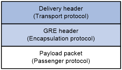
GRE encapsulation format
As shown in Figure 1, a GRE-tunneled packet includes the following parts:
· Payload packet—Original packet. The protocol type of the payload packet is called the passenger protocol. The passenger protocol can be any network layer protocol.
· GRE header—Header that is added to the payload packet to change the payload packet to a GRE packet. A GRE header includes the number of encapsulations, version, passenger protocol type, checksum, and key. GRE is called the encapsulation protocol.
· Delivery header—Header that is added to the GRE packet to deliver it to the tunnel end. The transport protocol (or delivery protocol) is the network layer protocol that transfers GRE packets.
The device supports GRE tunnels with IPv4 and IPv6 as the transport protocols. When the transport protocol is IPv4, the GRE tunnel mode is GRE over IPv4 (GRE/IPv4). When the transport protocol is IPv6, the GRE tunnel mode is GRE over IPv6 (GRE/IPv6).
Figure 1 GRE encapsulation format
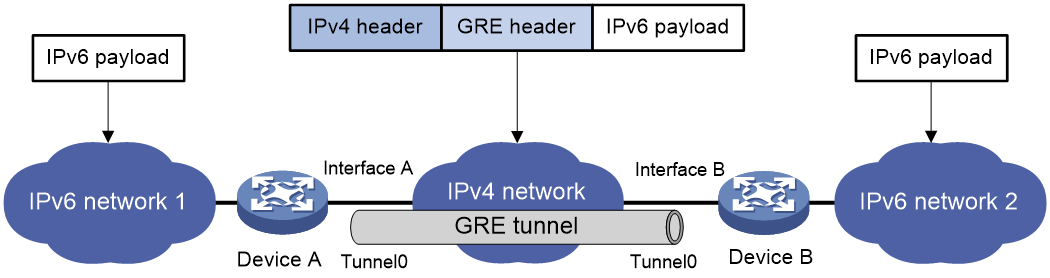
GRE tunnel operating principle
As shown in Figure 2, an IPv6 protocol packet traverses an IPv4 network through a GRE tunnel as follows:
1. After receiving an IPv6 packet from the interface connected to IPv6 network 1, Device A processes the packet as follows:
a. Looks up the routing table to identify the outgoing interface for the IPv6 packet.
b. Submits the IPv6 packet to the outgoing interface—the GRE tunnel interface Tunnel 0.
2. Upon receiving the packet, the tunnel interface encapsulates the packet with GRE and then with IPv4. In the IPv4 header:
¡ The source address is the tunnel's source address (the IP address of Interface A of Device A).
¡ The destination address is the tunnel's destination address (the IP address of Interface B of Device B).
3. Device A looks up the routing table according to the destination address in the IPv4 header, and forwards the IPv4 packet out of the physical interface (Interface A) of the GRE tunnel.
4. When the IPv4 arrives at the GRE tunnel destination Device B, Device B checks the destination address. Because the destination is Device B itself and the protocol number in the IP header is 47 (the protocol number for GRE), Device B submits the packet to GRE for de-encapsulation.
5. GRE first removes the IPv4 header, and then checks the GRE key, checksum, and packet sequence number. After GRE finishes the checking, it removes the GRE header, and submits the payload to the IPv6 protocol for forwarding.
Figure 2 IPv6 networks interconnected through a GRE tunnel
GRE security mechanisms
GRE supports the GRE key and GRE checksum security mechanisms.
GRE key
GRE keys ensure packet validity. The sender adds a GRE key into a packet. The receiver compares the GRE key with its own GRE key. If the two keys are the same, the receiver accepts the packet. If the two keys are different, the receiver drops the packet.
GRE checksum
GRE checksums ensure packet integrity. The sender calculates a checksum for the GRE header and payload and sends the packet containing the checksum to the tunnel peer. The receiver calculates a checksum for the received packet and compares it with that carried in the packet. If the checksums are the same, the receiver considers the packet intact and continues to process the packet. If the checksums are different, the receiver discards the packet.
GRE application scenarios
The following shows typical GRE application scenarios:
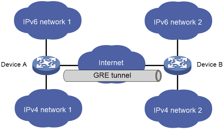
Connecting networks running different protocols over a single backbone
As shown in Figure 3, IPv6 network 1 and IPv6 network 2 are IPv6 networks, and IPv4 network 1 and IPv4 network 2 are IPv4 networks. Through the GRE tunnel between Device A and Device B, IPv6 network 1 can communicate with IPv6 network 2 and IPv4 network 1 can communicate with IPv4 network 2, without affecting each other.
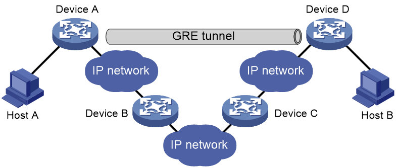
Enlarging network scope
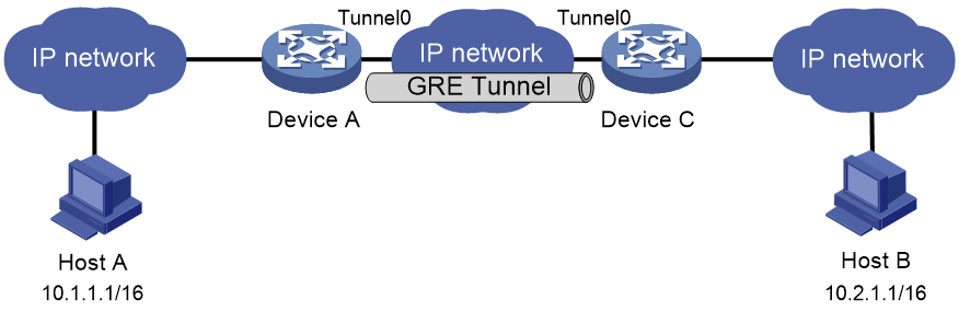
In an IP network, the maximum TTL value of a packet is 255. If two devices have more than 255 hops in between, they cannot communicate with each other. By using a GRE tunnel, you can hide some hops to enlarge the network scope. As shown in Figure 4, only the tunnel-end devices (Device A and Device D) of the GRE tunnel are counted in hop count calculation. Therefore, there are only three hops between Host A and Host B.
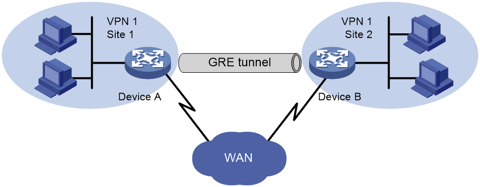
Constructing VPN
As shown in Figure 5, Site 1 and Site 2 both belong to VPN 1 and are located in different cities. Using a GRE tunnel can connect the two VPN sites across the WAN.
Operating with IPsec
As shown in Figure 6, GRE can be used together with IPsec to form a GRE over IPsec tunnel. Packets (for example, routing protocol packets, voice data, and video data) are first encapsulated with GRE and then with IPsec. GRE over IPsec delivers the following benefits:
· Improves transmission security.
· Allows IPsec to protect not only unicast packets. GRE supports encapsulating multicast, broadcast, and non-IP packets. After GRE encapsulation, these packets become common unicast packets, which can be protected by IPsec.
· Simplifies IPsec configuration. Packets are first encapsulated by GRE. You can define the packets to be protected by IPsec according to the GRE tunnel's source and destination addresses, without considering the source and destination addresses of the original packets.
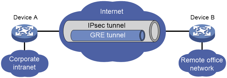
GRE and IPsec can also form IPsec over GRE tunnels. As a best practice, use GRE over IPsec tunnels instead of IPsec over GRE tunnels.
For more information about IPsec, see Security Configuration Guide.
Protocols and standards
· RFC 1701, Generic Routing Encapsulation (GRE)
· RFC 1702, Generic Routing Encapsulation over IPv4 networks
· RFC 2784, Generic Routing Encapsulation (GRE)
· RFC 2890, Key and Sequence Number Extensions to GRE
Restrictions and guidelines: GRE configuration
When you configure a GRE tunnel, follow these restrictions and guidelines:
· You must configure the tunnel source address and destination address at both ends of a tunnel. The tunnel source or destination address at one end must be the tunnel destination or source address at the other end.
· As a best practice, do not configure the same tunnel source and destination addresses for local tunnel interfaces that use the same tunnel mode.
· Do not configure the same tunnel source and destination addresses for a GRE tunnel interface and a GRE P2MP tunnel interface.
· You can enable or disable GRE checksum at each end of a tunnel. If GRE checksum is enabled at a tunnel end, the tunnel end sends packets carrying the checksum to the peer end. A tunnel end checks the GRE checksum of a received packet if the packet carries a GRE checksum, whether or not the tunnel end is enabled with GRE checksum.
· To ensure correct packet forwarding, identify whether the destination network of packets and the IP address of the local tunnel interface are on the same subnet. If they are not, configure a route reaching the destination network through the tunnel interface. You can configure the route by using one of the following methods:
¡ Configure a static route, using the local tunnel interface as the outgoing interface of the route.
¡ Enable a dynamic routing protocol on both the tunnel interface and the interface connecting the private network. This allows the dynamic routing protocol to establish a routing entry with the tunnel interface as the outgoing interface.
· GRE encapsulation and de-encapsulation can decrease the forwarding efficiency of tunnel-end devices.
Configuring a GRE/IPv4 tunnel
Restrictions and guidelines
This task describes only GRE/IPv4 tunnel required tunnel interface commands (the interface tunnel, source, and destination commands). For more tunnel interface commands, see "Configuring tunneling."
Procedure
1. Enter system view.
system-view
2. Create a GRE tunnel interface, and specify the tunnel mode as GRE/IPv4.
interface tunnel number mode gre
You must configure the same tunnel mode on both ends of a tunnel. Otherwise, packet delivery might fail.
3. Configure an IP address for the tunnel interface based on the passenger protocol.
IPv4:
For information about how to assign an IPv4 address to an interface, see "Configuring IP addressing."
IPv6:
For information about how to assign an IPv6 address to an interface, see "Configuring basic IPv6 settings."
By default, no IP address is configured for a tunnel interface.
4. Configure a source address or source interface for the tunnel.
source { ip-address | interface-type interface-number }
By default, no source address or interface is configured for a tunnel.
If you configure a source address, the tunnel interface uses the source address as the source address of encapsulated packets.
If you configure a source interface, the tunnel interface uses the primary IP address of the source interface as the source address of encapsulated packets.
5. Configure a destination address for the tunnel.
destination ip-address
By default, no destination address is configured for a tunnel.
The destination address is the address of the physical interface that the tunnel remote end uses to receive packets from the GRE tunnel.
The tunnel local end uses this address as the destination address of encapsulated packets.
The tunnel destination address and the IP address of the tunnel interface must be in different subnets.
6. (Optional.) Enable GRE keepalive, and set the keepalive interval and keepalive number.
keepalive [ interval [ times ] ]
By default, GRE keepalive is disabled.
7. (Optional.) Configure GRE security mechanisms.
¡ Enable GRE checksum.
gre checksum
By default, GRE checksum is disabled.
¡ Configure a GRE key for the GRE tunnel interface.
gre key key
By default, no GRE key is configured for a GRE tunnel interface.
The two ends of a GRE tunnel must have the same key or both have no key.
8. (Optional.) Set the DF bit for encapsulated packets.
tunnel dfbit enable
By default, the DF bit is not set, allowing encapsulated packets to be fragmented.
9. (Optional.) Specify a service class value for the GRE tunnel interface.
service-class service-class-value
By default, no service class value is specified for a GRE tunnel interface.
Configuring a GRE/IPv6 tunnel
Restrictions and guidelines
This task describes only GRE/IPv6 tunnel required tunnel interface commands (the interface tunnel, source, and destination commands). For more tunnel interface commands, see "Configuring tunneling."
Procedure
1. Enter system view.
system-view
2. Create a GRE tunnel interface, and specify the tunnel mode as GRE/IPv6.
interface tunnel number mode gre ipv6
You must configure the same tunnel mode on both ends of a tunnel. Otherwise, packet delivery might fail.
3. Configure an IP address for the tunnel interface based on the passenger protocol.
IPv4:
For information about how to assign an IPv4 address to an interface, see "Configuring IP addressing."
IPv6:
For information about how to assign an IPv6 address to an interface, see "Configuring basic IPv6 settings."
By default, no IP address is configured for a tunnel interface.
4. Configure a source IPv6 address or source interface for the tunnel.
source { ipv6-address | interface-type interface-number }
By default, no source IPv6 address or interface is configured for a tunnel.
If you configure a source IPv6 address, the tunnel interface uses the source IPv6 address as the source IPv6 address of encapsulated packets.
If you configure a source interface, the tunnel interface uses the IPv6 address of the source interface as the source IPv6 address of encapsulated packets.
5. Configure a destination IPv6 address for the tunnel.
destination ipv6-address
By default, no destination IPv6 address is configured for a tunnel.
The destination IPv6 address is the IPv6 address of the physical interface that the tunnel remote end uses to receive packets from the GRE tunnel.
The tunnel local end uses this address as the destination IPv6 address of encapsulated packets.
The tunnel destination address and the IP address of the tunnel interface must be in different subnets.
6. (Optional.) Configure GRE security mechanisms.
¡ Enable GRE checksum.
gre checksum
By default, GRE checksum is disabled.
¡ (Optional.) Configure a GRE key for the tunnel interface.
gre key key
By default, no GRE key is configured for a GRE tunnel interface.
The two ends of a GRE tunnel must have the same key or both have no key.
7. (Optional.) Specify a service class value for the GRE tunnel interface.
service-class service-class-value
By default, no service class value is specified for a GRE tunnel interface.
Enabling dropping IPv6 packets that use IPv4-compatible IPv6 addresses
About this task
This feature enables the device to check the source and destination IPv6 addresses of the de-encapsulated IPv6 packets from a tunnel. If a packet uses an IPv4-compatible IPv6 address as the source or destination address, the device discards the packet.
Procedure
1. Enter system view.
system-view
2. Configure the device to discard IPv6 packets with IPv4-compatible IPv6 addresses.
tunnel discard ipv4-compatible-packet
By default, the device does not discard such IPv6 packets.
For more information about this command, see tunneling in Layer 3—IP Services Command Reference.
Display and maintenance commands for GRE
Execute display commands in any view and reset commands in user view.
|
Task |
Command |
Remarks |
|
Display information about tunnel interfaces. |
display interface [ tunnel [ number ] ] [ brief [ description | down ] ] |
For more information about the commands, see tunneling in Layer 3—IP Services Command Reference. |
|
Display IPv6 information about tunnel interface. |
display ipv6 interface [ tunnel [ number ] ] [ brief ] |
For more information about this command, see IPv6 basics in Layer 3—IP Services Command Reference. |
|
Clear tunnel interface statistics. |
reset counters interface [ tunnel [ number ] ] |
For more information about this command, see tunneling in Layer 3—IP Services Command Reference. |
|
Clear IPv6 statistics on tunnel interfaces. |
In standalone mode: reset ipv6 statistics In IRF mode: reset ipv6 statistics [ slot slot-number ] |
For more information about this command, see IPv6 basics in Layer 3—IP Services Command Reference. |
GRE configuration examples
Example: Configuring an IPv4 over IPv4 GRE tunnel
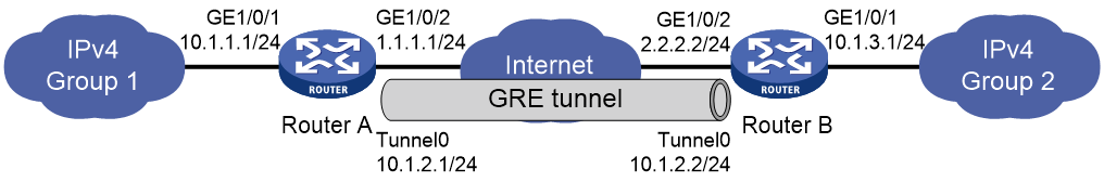
Network configuration
As shown in Figure 7, Group 1 and Group 2 are two private IPv4 networks. The two networks both use private network addresses and belong to the same VPN. Establish a GRE tunnel between Router A and Router B to interconnect the two private IPv4 networks Group 1 and Group 2.
Procedure
Before performing the following configuration, configure an IP address for each interface, and make sure Router A and Router B can reach each other.
1. Configure Router A:
# Create a tunnel interface Tunnel 0, and specify the tunnel mode as GRE/IPv4.
<RouterA> system-view
[RouterA] interface tunnel 0 mode gre
# Configure an IP address for the tunnel interface.
[RouterA-Tunnel0] ip address 10.1.2.1 255.255.255.0
# Configure the source address of the tunnel as the IP address of GigabitEthernet 1/0/2 on Router A.
[RouterA-Tunnel0] source 1.1.1.1
# Configure the destination address of the tunnel as the IP address of GigabitEthernet 1/0/2 on Router B.
[RouterA-Tunnel0] destination 2.2.2.2
[RouterA-Tunnel0] quit
# Configure a static route from Router A through the tunnel to Group 2.
[RouterA] ip route-static 10.1.3.0 255.255.255.0 tunnel 0
2. Configure Router B:
# Create tunnel interface Tunnel 0 and specify the tunnel mode as GRE/IPv4.
<RouterB> system-view
[RouterB] interface tunnel 0 mode gre
# Configure an IP address for the tunnel interface.
[RouterB-Tunnel0] ip address 10.1.2.2 255.255.255.0
# Configure the source address of the tunnel as the IP address of interface GigabitEthernet 1/0/2 on Router B.
[RouterB-Tunnel0] source 2.2.2.2
# Configure the destination address of the tunnel as the IP address of interface GigabitEthernet 1/0/2 on Router A.
[RouterB-Tunnel0] destination 1.1.1.1
[RouterB-Tunnel0] quit
# Configure a static route from Router B through the tunnel to Group 1.
[RouterB] ip route-static 10.1.1.0 255.255.255.0 tunnel 0
Verifying the configuration
# Display tunnel interface information on Router A.
[RouterA] display interface tunnel 0
Tunnel0
Current state: UP
Line protocol state: UP
Description: Tunnel0 Interface
Bandwidth: 64kbps
Maximum transmission unit: 1476
Internet address: 10.1.2.1/24 (primary)
Tunnel source 1.1.1.1, destination 2.2.2.2
Tunnel keepalive disabled
Tunnel TTL 255
Tunnel protocol/transport GRE/IP
GRE key disabled
Checksumming of GRE packets disabled
Output queue - Urgent queuing: Size/Length/Discards 0/100/0
Output queue - Protocol queuing: Size/Length/Discards 0/500/0
Output queue - FIFO queuing: Size/Length/Discards 0/75/0
Last clearing of counters: Never
Last 300 seconds input rate: 0 bytes/sec, 0 bits/sec, 0 packets/sec
Last 300 seconds output rate: 0 bytes/sec, 0 bits/sec, 0 packets/sec
Input: 0 packets, 0 bytes, 0 drops
Output: 0 packets, 0 bytes, 0 drops
# Display tunnel interface information on Router B.
[RouterB] display interface tunnel 0
Tunnel0
Current state: UP
Line protocol state: UP
Description: Tunnel0 Interface
Bandwidth: 64kbps
Maximum transmission unit: 1476
Internet address: 10.1.2.2/24 (primary)
Tunnel source 2.2.2.2, destination 1.1.1.1
Tunnel keepalive disabled
Tunnel TTL 255
Tunnel protocol/transport GRE/IP
GRE key disabled
Checksumming of GRE packets disabled
Output queue - Urgent queuing: Size/Length/Discards 0/100/0
Output queue - Protocol queuing: Size/Length/Discards 0/500/0
Output queue - FIFO queuing: Size/Length/Discards 0/75/0
Last clearing of counters: Never
Last 300 seconds input rate: 0 bytes/sec, 0 bits/sec, 0 packets/sec
Last 300 seconds output rate: 0 bytes/sec, 0 bits/sec, 0 packets/sec
Input: 0 packets, 0 bytes, 0 drops
Output: 0 packets, 0 bytes, 0 drops
# From Router B, ping the IP address of GigabitEthernet 1/0/1 on Router A.
[RouterB] ping -a 10.1.3.1 10.1.1.1
Ping 10.1.1.1 (10.1.1.1) from 10.1.3.1: 56 data bytes, press CTRL_C to break
56 bytes from 10.1.1.1: icmp_seq=0 ttl=255 time=11.000 ms
56 bytes from 10.1.1.1: icmp_seq=1 ttl=255 time=1.000 ms
56 bytes from 10.1.1.1: icmp_seq=2 ttl=255 time=0.000 ms
56 bytes from 10.1.1.1: icmp_seq=3 ttl=255 time=0.000 ms
56 bytes from 10.1.1.1: icmp_seq=4 ttl=255 time=0.000 ms
--- Ping statistics for 10.1.1.1 ---
5 packet(s) transmitted, 5 packet(s) received, 0.0% packet loss
round-trip min/avg/max/std-dev = 0.000/2.400/11.000/4.317 ms
The output shows that Router B can successfully ping Router A.
Example: Configuring an IPv4 over IPv6 GRE tunnel
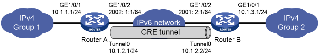
Network configuration
As shown in Figure 8, two IPv4 subnets Group 1 and Group 2 are connected to an IPv6 network. Create a GRE/IPv6 tunnel between Router A and Router B, so the two IPv4 subnets can communicate with each other through the GRE tunnel over the IPv6 network.
Procedure
Before performing the following configuration, configure an IP address for each interface, and make sure Router A and Router B can reach each other.
1. Configure Router A:
# Create a tunnel interface Tunnel 0, and specify the tunnel mode as GRE/IPv6.
<RouterA> system-view
[RouterA] interface tunnel 0 mode gre ipv6
# Configure an IP address for the tunnel interface.
[RouterA-Tunnel0] ip address 10.1.2.1 255.255.255.0
# Configure the source address of the tunnel as the IP address of interface GigabitEthernet 1/0/2 on Router A.
[RouterA-Tunnel0] source 2002::1:1
# Configure the destination address of the tunnel as the IP address of interface GigabitEthernet 1/0/2 on Router B.
[RouterA-Tunnel0] destination 2001::2:1
[RouterA-Tunnel0] quit
# Configure a static route from Router A through the tunnel to Group 2.
[RouterA] ip route-static 10.1.3.0 255.255.255.0 tunnel 0
2. Configure Router B:
# Create a tunnel interface Tunnel 0, and specify the tunnel mode as GRE/IPv6.
<RouterB> system-view
[RouterB] interface tunnel 0 mode gre ipv6
# Configure an IP address for the tunnel interface.
[RouterB-Tunnel0] ip address 10.1.2.2 255.255.255.0
# Configure the source address of the tunnel as the IP address of interface GigabitEthernet 1/0/2 on Router B.
[RouterB-Tunnel0] source 2001::2:1
# Configure the destination address of the tunnel as the IP address of interface GigabitEthernet 1/0/2 on Router A.
[RouterB-Tunnel0] destination 2002::1:1
[RouterB-Tunnel0] quit
# Configure a static route from Router B through the tunnel to Group 1.
[RouterB] ip route-static 10.1.1.0 255.255.255.0 tunnel 0
Verifying the configuration
# Display tunnel interface information on Router A.
[RouterA] display interface tunnel 0
Tunnel0
Current state: UP
Line protocol state: UP
Description: Tunnel0 Interface
Bandwidth: 64kbps
Maximum transmission unit: 1456
Internet address: 10.1.2.1/24 (primary)
Tunnel source 2002::1:1, destination 2001::2:1
Tunnel TTL 255
Tunnel protocol/transport GRE/IPv6
GRE key disabled
Checksumming of GRE packets disabled
Output queue - Urgent queuing: Size/Length/Discards 0/100/0
Output queue - Protocol queuing: Size/Length/Discards 0/500/0
Output queue - FIFO queuing: Size/Length/Discards 0/75/0
Last clearing of counters: Never
Last 300 seconds input rate: 0 bytes/sec, 0 bits/sec, 0 packets/sec
Last 300 seconds output rate: 0 bytes/sec, 0 bits/sec, 0 packets/sec
Input: 0 packets, 0 bytes, 0 drops
Output: 0 packets, 0 bytes, 0 drops
# Display tunnel interface information on Router B.
[RouterB] display interface tunnel 0
Tunnel0
Current state: UP
Line protocol state: UP
Description: Tunnel0 Interface
Bandwidth: 64kbps
Maximum transmission unit: 1456
Internet address: 10.1.2.2/24 (primary)
Tunnel source 2001::2:1, destination 2002::1:1
Tunnel TTL 255
Tunnel protocol/transport GRE/IPv6
GRE key disabled
Checksumming of GRE packets disabled
Output queue - Urgent queuing: Size/Length/Discards 0/100/0
Output queue - Protocol queuing: Size/Length/Discards 0/500/0
Output queue - FIFO queuing: Size/Length/Discards 0/75/0
Last clearing of counters: Never
Last 300 seconds input rate: 0 bytes/sec, 0 bits/sec, 0 packets/sec
Last 300 seconds output rate: 0 bytes/sec, 0 bits/sec, 0 packets/sec
Input: 0 packets, 0 bytes, 0 drops
Output: 0 packets, 0 bytes, 0 drops
# From Router B, ping the IP address of interface GigabitEthernet 1/0/1 on Router A.
[RouterB] ping -a 10.1.3.1 10.1.1.1
Ping 10.1.1.1 (10.1.1.1) from 10.1.3.1: 56 data bytes, press CTRL_C to break
56 bytes from 10.1.1.1: icmp_seq=0 ttl=255 time=2.000 ms
56 bytes from 10.1.1.1: icmp_seq=1 ttl=255 time=1.000 ms
56 bytes from 10.1.1.1: icmp_seq=2 ttl=255 time=1.000 ms
56 bytes from 10.1.1.1: icmp_seq=3 ttl=255 time=0.000 ms
56 bytes from 10.1.1.1: icmp_seq=4 ttl=255 time=1.000 ms
--- Ping statistics for 10.1.1.1 ---
5 packet(s) transmitted, 5 packet(s) received, 0.0% packet loss
round-trip min/avg/max/std-dev = 0.000/1.000/2.000/0.632 ms
The output shows that Router B can successfully ping Router A.
Troubleshooting GRE
The key to configuring GRE is to keep the configuration consistent. Most faults can be located by using the debugging gre or debugging tunnel command. This section analyzes one type of fault for illustration, with the scenario shown in Figure 9.
Hosts at both ends of a GRE tunnel cannot ping each other
Symptom
The interfaces at both ends of the tunnel are configured correctly and can ping each other, but Host A and Host B cannot ping each other.
Solution
To resolve the issue:
1. Execute the display ip routing-table command on Device A and Device C to view whether Device A has a route over tunnel 0 to 10.2.0.0/16 and whether Device C has a route over tunnel 0 to 10.1.0.0/16.
2. If such a route does not exist, execute the ip route-static command in system view to add the route. Take Device A as an example:
[DeviceA] ip route-static 10.2.0.0 255.255.0.0 tunnel 0
3. If the issue persists, contact H3C Support.
Configuring GRE P2MP tunnels
About GRE P2MP tunnels
The GRE point-to-multipoint (P2MP) tunnel technology allows the device to use a GRE P2MP tunnel interface to establish a tunnel with multiple destinations.
Application scenario
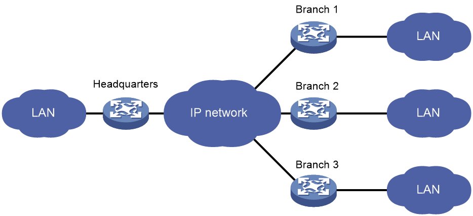
As shown in Figure 10, an enterprise has multiple branches. For the headquarters to communicate with the branches through tunnels, you can deploy GRE P2MP.
Configure a GRE P2MP tunnel interface on the gateway of the headquarters. Configure GRE/IPv4 or GRE/IPv6 tunnel interfaces (also called point-to-point GRE tunnel interfaces) on the gateways of the branch networks. Use the GRE P2MP tunnel interface on the headquarters gateway to set up a point-to-multipoint tunnel with the point-to-point GRE tunnel interfaces on the branch gateways.
Figure 10 GRE P2MP tunnel application
Benefits
Compared with GRE point-to-point tunnels and other dynamic VPN technologies, GRE P2MP has the following benefits:
· Simplified configuration—One GRE P2MP tunnel interface can set up a point-to-multipoint tunnel with multiple point-to-point GRE tunnel interfaces. You do not need to create multiple GRE tunnel interfaces for the headquarters gateway to establish point-to-point tunnels with each branch.
· Easy maintenance—When a new branch is added, the headquarters gateway can dynamically learn the tunnel destination address through GRE packets received from the branch. The gateway can automatically set up a tunnel with the branch. Manual configuration is not required.
· Flexible access—The headquarters can dynamically learn the tunnel destination addresses. Whether the branch network obtains public addresses dynamically or not does not affect the configuration in the headquarters.
· Good interoperability and decreased TCO—The device implements GRE P2MP based on the standard GRE protocol. It does not require other proprietary protocols. GRE P2MP does not have special requirements for the branch gateways. You can use any devices that support GRE as branch gateways.
· High availability—Support for tunnel backup in the headquarters and branches.
Working mechanisms
GRE uses the same packet encapsulation and de-encapsulation processes for point-to-multipoint and point-to-point tunnels.
When the device uses a GRE P2MP tunnel to forward traffic, it searches the tunnel entries for the tunnel destination address based on the packet destination IP address. GRE encapsulates the tunnel destination address as the destination IP address in the GRE transport protocol header.
GRE P2MP tunnel entries include dynamic entries and static entries. Dynamic and static entries cannot coexist.
GRE P2MP dynamic tunnel entry learning
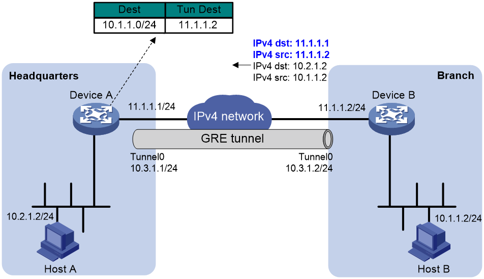
As shown in Figure 11, Device A dynamically learns GRE P2MP tunnel entry information (tunnel destination address and packet destination address) from the GRE packets received from the branch. The tunnel destination address is the source IP address in the transport protocol header of the received GRE packet. The packet destination address (branch network address) is the source IP address in passenger protocol header of the received GRE packet.
Figure 11 Dynamically learning a GRE P2MP tunnel entry
GRE P2MP static tunnel entry configuration
In a dynamic GRE P2MP tunnel network, the headquarters gateway cannot actively send packets to branch networks. If the gateway does not receive GRE packets from a branch, it cannot create a dynamic tunnel entry for the branch. To resolve this issue, you can configure GRE P2MP static tunnel entries by applying a GRE P2MP tunnel template to the GRE P2MP tunnel interface. The tunnel mapping entries in the tunnel template are static tunnel entries. A static tunnel entry includes the following information:
· Tunnel destination address.
· Branch network address.
· VPN instance of the branch network.
In the current software version, the device supports only IPv4 static tunnel entries for GRE P2MP.
GRE P2MP tunnel backup
This feature applies only to dynamic GRE P2MP tunnels.
GRE tunnel backup in branches
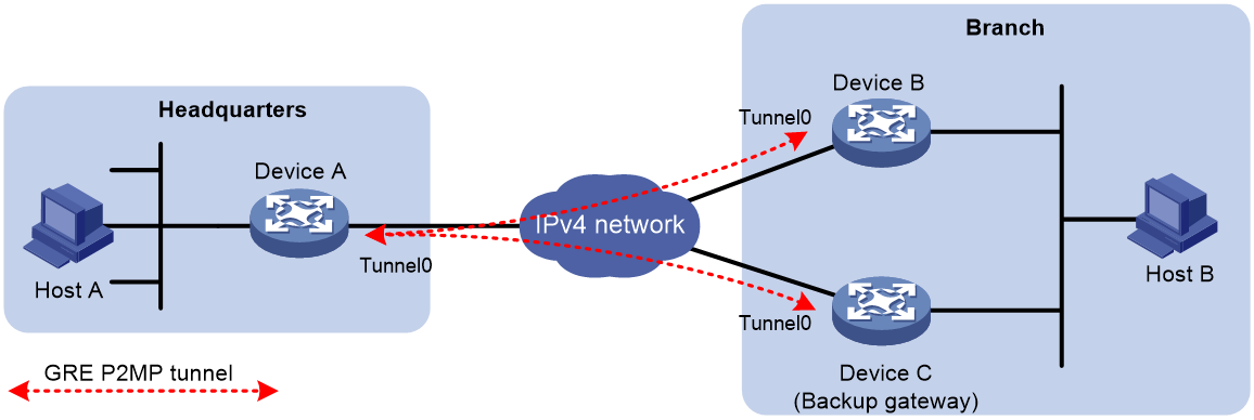
As shown in Figure 12, deploy redundant gateways in the branch network. Configure a GRE P2MP tunnel interface on the gateway of the headquarters. Use the GRE P2MP tunnel interface to set up a dynamic P2MP tunnel with each branch gateway.
Assign different GRE keys to the tunnel interfaces on the branch gateways. The headquarters gateway selects a dynamic tunnel entry for the branch in the following order:
1. The dynamic tunnel entry that does not have a GRE key.
2. The dynamic tunnel entry that has a GRE key with a lower value.
3. The latest learned dynamic tunnel entry.
Figure 12 GRE tunnel backup in a branch
GRE tunnel backup in the headquarters
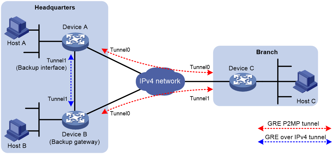
As shown in Figure 13, deploy redundant gateways in the headquarters, one primary and one backup. Configure a GRE P2MP tunnel interface and a GRE/IPv4 or GRE/IPv6 tunnel interface on each gateway. Specify the GRE/IPv4 or GRE/IPv6 tunnel interface on the primary gateway as the backup interface of its GRE P2MP tunnel interface.
When the primary gateway cannot reach the branch network, it sends the traffic destined for the branch network to the backup gateway through the backup interface. Then, the backup gateway sends the traffic to the destination.
The backup interface is also included for tunnel selection on the primary gateway. If the backup interface does not have a GRE key, its priority is lower than all GRE P2MP dynamic tunnel entries. If the backup interface has a GRE key, the headquarters gateway compares the GRE key with the GRE keys of GRE P2MP dynamic tunnel entries. The lower the value, the higher the priority.
Figure 13 Tunnel backup in the headquarters
Restrictions: Hardware compatibility with GRE P2MP tunnels
|
Hardware |
GRE P2MP tunnel compatibility |
|
MSR810, MSR810-W, MSR810-W-DB, MSR810-LM, MSR810-W-LM, MSR810-10-PoE, MSR810-LM-HK, MSR810-W-LM-HK, MSR810-LM-CNDE-SJK, MSR810-CNDE-SJK |
Yes |
|
MSR810-LMS, MSR810-LUS |
Yes |
|
MSR810-LMS-EA, MSR810-LME |
Yes |
|
MSR1004S-5G |
Yes |
|
MSR2600-6-X1, MSR2600-10-X1, MSR2600-15-X1 |
Yes |
|
MSR 2630 |
Yes |
|
MSR3600-28, MSR3600-51 |
Yes |
|
MSR3600-28-SI, MSR3600-51-SI |
No |
|
MSR3600-28-X1, MSR3600-28-X1-DP, MSR3600-51-X1, MSR3600-51-X1-DP |
Yes |
|
MSR3610-I-DP, MSR3610-IE-DP, MSR3610-IE-ES, MSR3610-IE-EAD, MSR-EAD-AK770, MSR3610-I-IG, MSR3610-IE-IG |
Yes |
|
MSR3610-X1, MSR3610-X1-DP, MSR3610-X1-DC, MSR3610-X1-DP-DC, MSR3620-X1, MSR3640-X1 |
Yes |
|
MSR 3610, MSR 3620, MSR 3620-DP, MSR 3640, MSR 3660 |
Yes |
|
MSR3610-G, MSR3620-G |
Yes |
|
MSR3640-X1-HI |
Yes |
|
Hardware |
GRE P2MP tunnel compatibility |
|
MSR810-W-WiNet, MSR810-LM-WiNet |
Yes |
|
MSR830-4LM-WiNet |
Yes |
|
MSR830-5BEI-WiNet, MSR830-6EI-WiNet, MSR830-10BEI-WiNet |
Yes |
|
MSR830-6BHI-WiNet, MSR830-10BHI-WiNet |
Yes |
|
MSR2600-6-WiNet, MSR2600-10-X1-WiNet |
Yes |
|
MSR2630-WiNet |
Yes |
|
MSR3600-28-WiNet |
Yes |
|
MSR3610-X1-WiNet |
Yes |
|
MSR3610-WiNet, MSR3620-10-WiNet, MSR3620-DP-WiNet, MSR3620-WiNet, MSR3660-WiNet |
Yes |
|
Hardware |
GRE P2MP tunnel compatibility |
|
MSR2630-XS |
Yes |
|
MSR3600-28-XS |
Yes |
|
MSR3610-XS |
Yes |
|
MSR3620-XS |
Yes |
|
MSR3610-I-XS |
Yes |
|
MSR3610-IE-XS |
Yes |
|
MSR3620-X1-XS |
Yes |
|
MSR3640-XS |
Yes |
|
MSR3660-XS |
Yes |
|
Hardware |
GRE P2MP tunnel compatibility |
|
MSR810-LM-GL |
Yes |
|
MSR810-W-LM-GL |
Yes |
|
MSR830-6EI-GL |
Yes |
|
MSR830-10EI-GL |
Yes |
|
MSR830-6HI-GL |
Yes |
|
MSR830-10HI-GL |
Yes |
|
MSR1004S-5G-GL |
Yes |
|
MSR2600-6-X1-GL |
Yes |
|
MSR3600-28-SI-GL |
No |
Restrictions and guidelines: GRE P2MP tunnel configuration
For more information about the interface tunnel, source, service, and tunnel discard ipv4-compatible-packet commands and additional configuration commands on a tunnel interface, see "Configuring tunneling" and tunneling commands in Layer 3—IP Services Command Reference.
Restrictions and guidelines for the headquarters end of a P2MP tunnel
When you configure the headquarters end of a P2MP tunnel, follow these restrictions and guidelines:
· Do not configure the same tunnel source address for multiple P2MP tunnel interfaces on the gateway.
· Do not configure the same tunnel source and destination addresses for a GRE P2MP tunnel interface and a GRE tunnel interface.
· Do not configure a GRE key on a GRE P2MP tunnel interface.
· You can specify a mask or prefix length for the headquarters gateway to create dynamic tunnel entries for branch networks. The gateway generates only one dynamic tunnel entry for each branch. Make sure the gateway can reach the devices in all branches by using the dynamic tunnel entries.
Restrictions and guidelines for the branch ends of a P2MP tunnel
The branch networks cannot communicate with one another. They do not have tunnels to reach one another.
When you configure the branch ends of a P2MP tunnel, follow these restrictions and guidelines:
· The tunnel destination address at each branch end must be the tunnel source address configured on the P2MP tunnel interface on the headquarters.
· On each gateway, the IP address of the tunnel interface and the tunnel destination address configured on the tunnel interface must be in different subnets.
· You can configure GRE keys on the branch GRE tunnel interfaces for the headquarters to determine the dynamic tunnel entry priority of each branch.
Restrictions and guidelines for all ends of a P2MP tunnel
The following restrictions and guidelines apply to all ends of a P2MP tunnel:
· You can enable or disable GRE checksum at each end of a tunnel. If GRE checksum is enabled at a tunnel end, the tunnel end sends packets carrying the checksum to the peer end. A tunnel end checks the GRE checksum of a received packet if the packet carries a GRE checksum, whether or not the tunnel end is enabled with GRE checksum.
· Configure routes reaching the destination networks through the local tunnel interface. You can configure the routes by using one of the following methods:
¡ Configure static routes, using the local tunnel interface as the outgoing interface of the routes.
¡ Enable a dynamic routing protocol on both the tunnel interface and the interface connecting the private network. This allows the dynamic routing protocol to establish routing entries with the tunnel interface as the outgoing interface.
· Dynamic entry-based GRE P2MP tunnels cannot forward private traffic.
GRE P2MP tunnel interface configuration tasks at a glance
To configure a GRE P2MP tunnel interface, perform the following tasks:
4. Configuring a GRE P2MP tunnel interface
Perform one of the following tasks:
¡ Configuring a GRE P2MP tunnel interface for dynamic entry-based tunnel setup
¡ Configuring a GRE P2MP tunnel interface for static entry-based tunnel setup
5. Specifying traffic processing slots for the tunnel interface
Configuring a GRE P2MP tunnel interface
Configuring a GRE P2MP tunnel interface for dynamic entry-based tunnel setup
1. Enter system view.
system-view
2. Create a GRE P2MP tunnel interface and enter tunnel interface view.
interface tunnel interface-number mode gre-p2mp [ ipv6 ]
In this mode, the transport and passenger protocols support both IPv4 and IPv6.
The other end of a GRE P2MP tunnel interface must be a GRE/IPv4 or GRE/IPv6 tunnel interface.
3. Configure an IP address for the tunnel interface.
IPv4:
For information about how to assign an IPv4 address to an interface, see "Configuring IP addressing."
IPv6:
For information about how to assign an IPv6 address to an interface, see "Configuring basic IPv6 settings."
By default, no IP address is configured for a tunnel interface.
4. Configure a source IP address or source interface for the tunnel.
source { ipv4-address | ipv6-address | interface-type interface-number }
By default, no source IP address or interface is configured for a tunnel.
If you configure a source IP address, the tunnel interface uses the source IP address as the source IP address of encapsulated packets.
If you configure a source interface, the tunnel interface uses the following IP address as the source IP address of encapsulated packets:
¡ Primary IP address of the source interface in an IPv4 network.
¡ The lowest IP address of the source interface in an IPv6 network.
5. (Optional.) Enable GRE checksum.
gre checksum
By default, GRE checksum is disabled.
6. (Optional.) Set an aging timer for dynamic tunnel entries of the GRE P2MP tunnel interface.
gre p2mp aging-time aging-time
By default, the aging timer is 5 seconds for dynamic tunnel entries of a GRE P2MP tunnel interface.
7. (Optional.) Specify a backup interface for the GRE P2MP tunnel interface.
gre p2mp backup-interface tunnel number
By default, no backup interface is specified for a GRE P2MP tunnel interface.
The backup interface must be a GRE/IPv4 or GRE/IPv6 tunnel interface. The backup interface must exist.
8. (Optional.) Specify an IPv4 address mask or IPv6 address prefix for the branch networks.
gre p2mp branch-network-mask { mask | mask-length | ipv6 prefix-length }
By default, the IPv4 address mask is 255.255.255.255 (the mask length is 32) and the IPv6 address prefix length is 128.
9. (Optional.) Enable next hop host route learning.
gre p2mp nexthop-learning
By default, next hop host route learning is disabled.
This command is supported only on GRE/IPv4 P2MP tunnel interfaces.
10. Return to system view.
quit
11. (Optional.) Enable dropping IPv6 packets that use IPv4-compatible IPv6 addresses.
tunnel discard ipv4-compatible-packet
By default, IPv6 packets that use IPv4-compatible IPv6 packets are not dropped.
Configuring a GRE P2MP tunnel interface for static entry-based tunnel setup
1. Enter system view.
system-view
2. Create a GRE P2MP tunnel template and enter its view.
gre p2mp-template template-name
3. Configure a tunnel mapping entry.
map [ vpn-instance vpn-instance-name ] branch-network-address branch-network-address { mask | mask-length } tunnel-destination tunnel-dest-address [ checksum-fill checksum-value ]
By default, no tunnel mapping entries are configured for a GRE P2MP tunnel template.
Specify the checksum-fill checksum-value option depending on your network. The option might cause GRE checksum failures.
4. Return to system view.
quit
5. Create a GRE P2MP tunnel interface and enter its view.
interface tunnel interface-number mode gre-p2mp
The other end of a GRE P2MP tunnel interface must be a GRE/IPv4 tunnel interface.
6. Configure an IPv4 address for the tunnel interface.
For information about how to assign an IPv4 address to an interface, see "Configuring IP addressing."
By default, no IPv4 address is configured for a tunnel interface.
7. Configure a source IP address or source interface for the tunnel.
source { ipv4-address | interface-type interface-number }
By default, no source IP address or interface is configured for a tunnel.
If you configure a source IP address, the tunnel interface uses the source IP address as the source IP address of encapsulated packets.
If you configure a source interface, the tunnel interface uses the primary IP address of the source interface as the source IP address of encapsulated packets.
8. Apply the GRE P2MP tunnel template to the tunnel interface.
gre p2mp-template template-name
By default, no GRE P2MP tunnel template is applied to a GRE P2MP tunnel interface.
You must specify an existing GRE P2MP tunnel template for this command.
9. (Optional.) Enable GRE checksum.
gre checksum
By default, GRE checksum is disabled.
10. (Optional.) Configure the preference of static routes issued by the tunnel mapping entries in the GRE P2MP tunnel template.
tunnel route-static [ preference preference-value ]
By default, the preference is 60.
Specifying traffic processing slots for the tunnel interface
About this task
Specify a traffic processing slot if a feature (for example, IPsec antireplay) requires that all traffic on a tunnel interface be processed on the same slot.
For high availability, you can specify one primary and one backup traffic processing slot by using the service command and the service standby command, respectively.
If you specify both primary and backup slots for an interface, traffic on that interface is processed as follows:
· The backup slot takes over when the primary slot becomes unavailable. The backup slot continues to process traffic for the interface after the primary slot becomes available again. The switchover will not occur until the backup slot becomes unavailable.
· When no specified traffic processing slots are available, the traffic is processed on the slot at which it arrives. Then, the processing slot that first becomes available again takes over.
If you do not specify a primary or a backup traffic processing slot for an interface, traffic on that interface is processed on the slot at which the traffic arrives.
Restrictions and guidelines
To avoid processing slot switchover, specify the primary slot before specifying the backup slot. If you specify the backup slot before specifying the primary slot, traffic is switched over to the primary slot immediately after you specify the primary slot.
For more information about the service and service standby commands, see tunneling in Layer 3—IP Services Command Reference.
Procedure
1. Enter system view.
system-view
2. Enter tunnel interface view.
interface tunnel number
3. Specify a primary traffic processing slot for the tunnel interface.
service slot slot-number
By default, no primary traffic processing slot is specified for a tunnel interface.
4. Specify a backup traffic processing slot for the tunnel interface.
service standby slot slot-number
By default, no backup traffic processing slot is specified for a tunnel interface.
Display and maintenance commands for GRE P2MP tunnels
Execute display commands in any view and reset commands in user view.
|
Task |
Command |
|
Display dynamic tunnel entry information for a GRE P2MP tunnel interface. |
display gre p2mp tunnel-table interface tunnel number [ ipv4 | ipv6 ] |
|
Display packet statistics of static tunnel entries for a GRE P2MP tunnel interface. |
display gre p2mp tunnel-table statistics interface tunnel number [ vpn-instance vpn-instance-name ] [ branch-network-address branch-network-address { mask | mask-length } ] |
|
Clear dynamic tunnel entry information for a GRE P2MP tunnel interface. |
reset gre p2mp tunnel-table interface tunnel number [ destination { dest-address | ipv6 dest-ipv6-address } tunnel-destination { tunnel-dest-address | ipv6 tunnel-dest-address } ] |
|
Clear packet statistics of static tunnel entries for a GRE P2MP tunnel interface. |
reset gre p2mp tunnel-table statistics interface tunnel number [ vpn-instance vpn-instance-name ] [ branch-network-address branch-network-address { mask | mask-length } ] |
GRE P2MP tunnel configuration examples
Example: Configuring a dynamic entry-based GRE P2MP tunnel
Network configuration
As shown in Figure 14, Router A is the gateway of the headquarters, and Router B and Router C are the gateways of the branches.
Configure the devices to meet the following requirements:
· Router A can dynamically set up a GRE P2MP tunnel with multiple branch gateways.
· Router B and Router C each can set up a GRE tunnel with Router A.
· Branch 1 and Branch 2 cannot communicate.
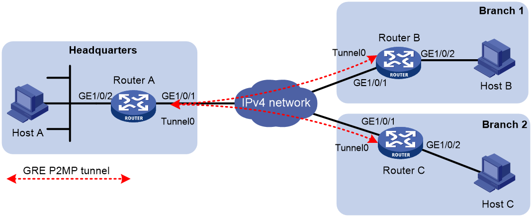
Table 1 IP address assignment
|
Device |
Interface |
IP address |
Device |
Interface |
IP address |
|
Router A |
GE1/0/1 |
11.1.1.1/24 |
Router B |
GE1/0/1 |
11.1.2.1/24 |
|
|
GE1/0/2 |
192.168.11.1/24 |
|
GE1/0/2 |
192.168.12.1/24 |
|
|
Tunnel 0 |
192.168.22.1/24 |
|
Tunnel 0 |
192.168.22.2/24 |
|
Router C |
GE1/0/1 |
11.1.3.1/24 |
|
|
|
|
|
GE1/0/2 |
192.168.13.1/24 |
|
|
|
|
|
Tunnel 0 |
192.168.22.3/24 |
|
|
|
Procedure
This example uses Router B to describe the gateway configuration for a branch. The gateway configuration for other branches is the same as the gateway configuration on Router B.
1. Configure IP addresses as shown in Figure 14. Make sure Router A and Router B have routes to each other, and Router A and Router C have routes to each other. (Details not shown.)
2. Configure Router A:
# Create tunnel interface Tunnel 0 and specify the tunnel mode as GRE P2MP.
<RouterA> system-view
[RouterA] interface tunnel 0 mode gre-p2mp
# Specify an IP address for the tunnel interface.
[RouterA-Tunnel0] ip address 192.168.22.1 255.255.255.0
# Specify the source IP address of the tunnel. The IP address is the IP address of GigabitEthernet 1/0/1 on Router A.
[RouterA-Tunnel0] source 11.1.1.1
# Specify the branch network mask as 255.255.255.0 for GRE P2MP dynamic tunnel entries on tunnel interface Tunnel 0.
[RouterA-Tunnel0] gre p2mp branch-network-mask 255.255.255.0
# Set the GRE P2MP dynamic tunnel entry aging timer to 20 seconds.
[RouterA-Tunnel0] gre p2mp aging-time 20
# Specify a primary traffic processing slot for the tunnel interface.
[RouterA-Tunnel0] service slot 1
[RouterA-Tunnel0] quit
# Configure a static route from Router A through Tunnel 0 to the branch.
[RouterA] ip route-static 192.168.12.0 255.255.255.0 tunnel 0
3. Configure Router B:
# Create tunnel interface Tunnel 0 and specify the tunnel mode as GRE/IPv4.
<RouterB> system-view
[RouterB] interface tunnel 0 mode gre
# Specify an IP address for the tunnel interface.
[RouterB-Tunnel0] ip address 192.168.22.2 255.255.255.0
# Specify the source IP address of the tunnel. The source IP address is the IP address of GigabitEthernet 1/0/1 on Router B.
[RouterB-Tunnel0] source 11.1.2.1
# Specify the destination address of the tunnel. The destination address is the IP address of GigabitEthernet 1/0/1 on Router A.
[RouterB-Tunnel0] destination 11.1.1.1
[RouterB-Tunnel0] quit
# Configure a static route from Router B through Tunnel 0 to the headquarters.
[RouterB] ip route-static 192.168.11.0 255.255.255.0 tunnel 0
Verifying the configuration
# Display GRE P2MP dynamic tunnel entries on Router A. The output shows that Router A does not have GRE P2MP dynamic tunnel entries.
[RouterA] display gre p2mp tunnel-table interface tunnel 0
Total number:0
Dest Addr Mask/Prefix Len Tunnel Dest Addr Gre Key Aging
# Ping Host A from Host B. The ping operation succeeds. (Details not shown.)
# Display GRE P2MP dynamic tunnel entries again on Router A. The output shows that Router A has created a GRE P2MP dynamic tunnel entry destined for the branch.
[RouterA] display gre p2mp tunnel-table interface tunnel 0
Total number:1
Dest Addr Mask/Prefix Len Tunnel Dest Addr Gre Key Aging
192.168.12.0 255.255.255.0 11.1.2.1 5
Example: Configuring a static entry-based GRE P2MP tunnel
Network configuration
As shown in Figure 15, Router A is the gateway of the headquarters, and Router B and Router C are the gateways of the branches.
Configure the devices as follows:
· On Router A, configure a GRE P2MP tunnel interface for the router to set up a GRE P2MP tunnel with multiple branch gateways.
· On Router A, configure a GRE P2MP tunnel template that contains tunnel mapping entries for Branch 1 and Branch 2. Apply the GRE P2MP tunnel template to the GRE P2MP tunnel interface so that the headquarters gateway can actively send packets to the branches.
· On Router B and Router C, configure GRE/IPv4 tunnel interfaces for them to set up GRE tunnels with Router A.

Table 2 IP address assignment
|
Device |
Interface |
IP address |
Device |
Interface |
IP address |
|
Router A |
GE1/0/1 |
11.1.1.1/24 |
Router B |
GE1/0/1 |
11.1.2.1/24 |
|
|
GE1/0/2 |
192.168.11.1/24 |
|
GE1/0/2 |
192.168.12.1/24 |
|
|
Tunnel 0 |
192.168.22.1/24 |
|
Tunnel 0 |
192.168.22.2/24 |
|
Router C |
GE1/0/1 |
11.1.3.1/24 |
|
|
|
|
|
GE1/0/2 |
192.168.13.1/24 |
|
|
|
|
|
Tunnel 0 |
192.168.22.3/24 |
|
|
|
Procedure
This example uses Router B to describe the gateway configuration for a branch. The gateway configuration for other branches is the same as the gateway configuration on Router B.
In this example, a tunnel mapping entry is configured for reaching Host B in Branch 1. The tunnel mapping entry configuration for reaching other devices or branch networks is the same as that for reaching Host B.
1. Configure IP addresses as shown in Figure 15. Make sure Router A and Router B have routes to each other, and Router A and Router C have routes to each other. (Details not shown.)
2. Configure Router A:
# Create a GRE P2MP tunnel template named aa and enter its view.
<RouterA> system-view
[RouterA] gre p2mp-template aa
# Configure a tunnel mapping entry. The branch network address is 192.168.12.2, the branch network mask length is 32, and the tunnel destination address is 11.1.2.1.
[RouterA-p2mp-template-aa] map branch-network-address 192.168.12.2 32 tunnel-destination 11.1.2.1
# Create tunnel interface Tunnel 0 and specify the tunnel mode as GRE P2MP.
[RouterA] interface tunnel 0 mode gre-p2mp
# Specify an IP address for the tunnel interface.
[RouterA-Tunnel0] ip address 192.168.22.1 255.255.255.0
# Specify the source IP address of the tunnel. The IP address is the IP address of GigabitEthernet 1/0/1 on Router A.
[RouterA-Tunnel0] source 11.1.1.1
# Apply GRE P2MP tunnel template aa to GRE P2MP tunnel interface Tunnel 0.
[RouterA-Tunnel0] gre p2mp-template aa
# Specify a primary traffic processing slot for the tunnel interface.
[RouterA-Tunnel0] service slot 1
[RouterA-Tunnel0] quit
3. Configure Router B:
# Create tunnel interface Tunnel 0 and specify the tunnel mode as GRE/IPv4.
<RouterB> system-view
[RouterB] interface tunnel 0 mode gre
# Specify an IP address for the tunnel interface.
[RouterB-Tunnel0] ip address 192.168.22.2 255.255.255.0
# Specify the source IP address of the tunnel. The source IP address is the IP address of GigabitEthernet 1/0/1 on Router B.
[RouterB-Tunnel0] source 11.1.2.1
# Specify the destination address of the tunnel. The destination address is the IP address of GigabitEthernet 1/0/1 on Router A.
[RouterB-Tunnel0] destination 11.1.1.1
[RouterB-Tunnel0] quit
# Configure a static route from Router B through Tunnel 0 to the headquarters.
[RouterB] ip route-static 192.168.11.0 255.255.255.0 tunnel 0
Verifying the configuration
# Verify that you can ping Host B from Host A. (Details not shown.)
# Display GRE P2MP static tunnel entries and packet statistics on Router A. The output shows that Router A has GRE P2MP static tunnel entries and packet statistics.
[RouterA] display gre p2mp tunnel-table statistics interface tunnel 0
VPN-instance name: - Map number: 1
Branch network address: 192.168.12.2/32
Tunnel destination address: 11.1.2.1
Input:
5 packets, 420 bytes, 0 drops
Output:
5 packets, 420 bytes, 0 drops
Example: Configuring GRE P2MP branch-side tunnel backup
Network configuration
As shown in Figure 16, Router A is the gateway of the headquarters, Router B is the gateway of the branch, and Router C is the backup gateway of the branch.
Configure the devices as follows:
· Configure a GRE P2MP tunnel interface on Router A. Router A uses the interface to establish a GRE P2MP tunnel with Router B and Router C.
· Configure a GRE/IPv4 tunnel interface on Router B and Router C, respectively. Router B and Router C use the tunnel interfaces to establish tunnels with Router A.
· Assign different GRE keys to the GRE/IPv4 tunnel interfaces on Router B and Router C. Router A selects the tunnel that has a GRE key with a higher priority to forward traffic. In this example, the tunnel destined for Router B has a higher priority.
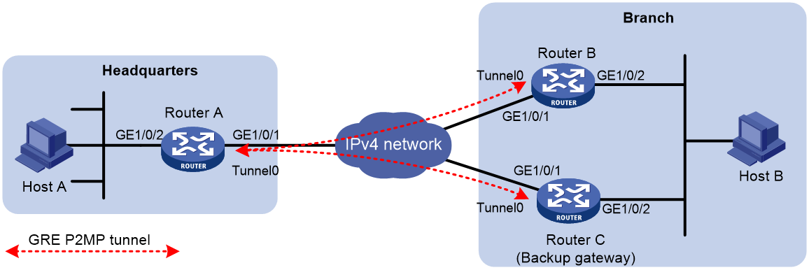
Table 3 IP address assignment
|
Device |
Interface |
IP address |
Device |
Interface |
IP address |
|
Router A |
GE1/0/1 |
11.1.1.1/24 |
Router B |
GE1/0/1 |
11.1.1.2/24 |
|
|
GE1/0/2 |
172.17.17.1/24 |
|
GE1/0/2 |
192.168.1.2/24 |
|
|
Tunnel 0 |
192.168.22.1/24 |
|
Tunnel 0 |
192.168.22.2/24 |
|
Router C |
GE1/0/1 |
11.1.1.3/24 |
|
|
|
|
|
GE1/0/2 |
192.168.1.3/24 |
|
|
|
|
|
Tunnel 0 |
192.168.22.3/24 |
|
|
|
Procedure
1. Configure IP addresses as shown in Figure 16. Make sure Router A, Router B, and Router C have routes to one another. (Details not shown.)
2. Configure Router A:
# Create tunnel interface Tunnel 0 and specify the tunnel mode as GRE P2MP.
<RouterA> system-view
[RouterA] interface tunnel 0 mode gre-p2mp
# Specify an IP address for the tunnel interface.
[RouterA-Tunnel0] ip address 192.168.22.1 255.255.255.0
# Specify the branch network mask as 255.255.255.0 for GRE P2MP dynamic tunnel entries on tunnel interface Tunnel 0.
[RouterA-Tunnel0] gre p2mp branch-network-mask 255.255.255.0
# Set the GRE P2MP dynamic tunnel entry aging timer to 20 seconds.
[RouterA-Tunnel0] gre p2mp aging-time 20
# Specify the source IP address of the tunnel. The IP address is the IP address of GigabitEthernet 1/0/1 on Router A.
[RouterA-Tunnel0] source 11.1.1.1
# Specify a primary traffic processing slot for the tunnel interface.
[RouterA-Tunnel0] service slot 1
[RouterA-Tunnel0] quit
# Configure a static route from Router A through Tunnel 0 to the branch.
[RouterA] ip route-static 192.168.1.0 255.255.255.0 tunnel 0
3. Configure Router B:
# Create tunnel interface Tunnel 0 and specify the tunnel mode as GRE/IPv4.
<RouterB> system-view
[RouterB] interface tunnel 0 mode gre
# Specify an IP address for the tunnel interface.
[RouterB-Tunnel0] ip address 192.168.22.2 255.255.255.0
# Specify the source IP address of the tunnel. The source IP address is the IP address of GigabitEthernet 1/0/1 on Router B.
[RouterB-Tunnel0] source 11.1.1.2
# Specify the destination address of the tunnel. The destination address is the IP address of GigabitEthernet 1/0/1 on Router A.
[RouterB-Tunnel0] destination 11.1.1.1
# Set the GRE key to 1 for the tunnel interface.
[RouterB-Tunnel0] gre key 1
[RouterB-Tunnel0] quit
# Configure a static route from Router B through Tunnel 0 to the headquarters.
[RouterB] ip route-static 172.17.17.0 255.255.255.0 tunnel 0
4. Configure Router C:
# Create tunnel interface Tunnel 0 and specify the tunnel mode as GRE/IPv4.
<RouterC> system-view
[RouterC] interface tunnel 0 mode gre
# Specify an IP address for the tunnel interface.
[RouterC-Tunnel0] ip address 192.168.22.3 255.255.255.0
# Specify the source IP address of the tunnel. The source IP address is the IP address of GigabitEthernet 1/0/1 on Router C.
[RouterC-Tunnel0] source 11.1.1.3
# Specify the destination address of the tunnel. The destination address is the IP address of GigabitEthernet 1/0/1 on Router A.
[RouterC-Tunnel0] destination 11.1.1.1
# Set the GRE key to 2 for the tunnel interface.
[RouterC-Tunnel0] gre key 2
[RouterC-Tunnel0] quit
# Configure a static route from Router C through Tunnel 0 to the headquarters.
[RouterC] ip route-static 172.17.17.0 255.255.255.0 tunnel 0
Verifying the configuration
# Configure Router C as the default gateway of Host B, and then ping Host A from Host B. The ping operation succeeds. (Details not shown.)
# Display GRE P2MP dynamic tunnel entries on Router A.
[RouterA] display gre p2mp tunnel-table interface tunnel 0
Total number:1
Dest Addr Mask/Prefix Len Tunnel Dest Addr Gre Key Aging
192.168.1.0 255.255.255.0 11.1.1.3 2 20
# Configure the default gateway of Host B as Router B, and then ping Host A from Host B. The ping operation succeeds. (Details not shown).
# Display GRE P2MP dynamic tunnel entries on Router A.
[RouterA] display gre p2mp tunnel-table interface tunnel 0
Total number:2
Dest Addr Mask/Prefix Len Tunnel Dest Addr Gre Key Aging
192.168.1.0 255.255.255.0 11.1.1.3 2 20
192.168.1.0 255.255.255.0 11.1.1.2 1 20
The output shows that Router A has two GRE P2MP dynamic tunnel entries destined for the branch. Router A prefers the dynamic tunnel entry with a lower GRE key value. The dynamic entry destined for Router B is preferred.
# Shut down tunnel interface Tunnel 0 on Router B.
[RouterB] interface tunnel 0
[RouterB-Tunnel0] shutdown
# Change the default gateway of Host B to Router C. (Details not shown.)
# Ping Host A from Host B after the GRE P2MP dynamic tunnel entry destined for Router B ages. The ping operation succeeds. (Details not shown.)
# Display GRE P2MP dynamic tunnel entries on Router A.
[RouterA] display gre p2mp tunnel-table interface tunnel 0
Total number:1
Dest Addr Mask/Prefix Len Tunnel Dest Addr Gre Key Aging
192.168.1.0 255.255.255.0 11.1.1.3 2 10
The output shows that Router A can forward traffic to hosts in the branch only through Router C.
Example: Configuring GRE P2MP headquarters-side tunnel backup
Network configuration
As shown in Figure 17, Router A is the gateway of the headquarters, Router B is the backup gateway of the headquarters, and Router C is the gateway of the branch.
Configure the devices as follows:
· Configure a GRE P2MP tunnel interface on Router A and Router B, respectively. Router A and Router B use the interfaces to establish GRE P2MP tunnels with Router C.
· Configure a GRE/IPv4 tunnel interface on Router A and Router B, respectively. Configure the GRE/IPv4 tunnel interface on Router A as the backup interface of the GRE P2MP tunnel interface. To avoid loops, do not configure the GRE/IPv4 tunnel interface on Router B as the backup interface of the GRE P2MP tunnel interface.
· Configure GRE/IPv4 tunnel interfaces on Router C for the router to establish tunnels with Router A and Router B.
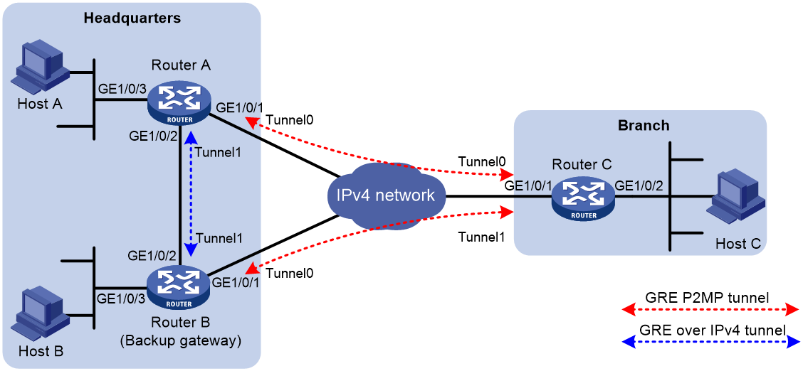
Table 4 IP address assignment
|
Device |
Interface |
IP address |
Device |
Interface |
IP address |
|
Router A |
GE1/0/1 |
11.1.1.1/24 |
Router B |
GE1/0/1 |
11.1.1.2/24 |
|
|
GE1/0/2 |
10.1.1.1/24 |
|
GE1/0/2 |
10.1.1.2/24 |
|
|
GE1/0/3 |
192.168.11.1/24 |
|
GE1/0/3 |
192.168.11.2/24 |
|
|
Tunnel 0 |
172.168.1.1/24 |
|
Tunnel 0 |
172.168.2.2/24 |
|
|
Tunnel 1 |
192.168.22.1/24 |
|
Tunnel 1 |
192.168.22.2/24 |
|
Router C |
GE1/0/1 |
11.1.1.3/24 |
|
|
|
|
|
GE1/0/2 |
192.168.12.1/24 |
|
|
|
|
|
Tunnel 0 |
172.168.1.3/24 |
|
|
|
|
|
Tunnel 1 |
172.168.2.3/24 |
|
|
|
Restrictions and guidelines
You need to disconnect the link between Router A and Router C to verify the tunnel backup feature. To make sure Router C can detect the link loss and switch the traffic forwarding path to the link connecting Router B, perform one of the following tasks:
· If Router C and Router A are directly connected, configure static routes on Router C.
· If Router C and Router A are not directly connected, use one of the following methods:
¡ Configure a dynamic routing protocol on Router A, Router B, and Router C.
¡ Configure static routes on Router C and associate the routes with track entries for detecting the route reachability status. For more information about track entries, see High Availability Configuration Guide.
This example uses the static routes method.
Procedure
1. Configure IP addresses as shown in Figure 17. Make sure Router A, Router B, and Router C have routes to one another. (Details not shown.)
2. Configure Router A:
# Create tunnel interface Tunnel 1 and specify the tunnel mode as GRE/IPv4.
<RouterA> system-view
[RouterA] interface tunnel 1 mode gre
# Specify an IP address for the tunnel interface.
[RouterA-Tunnel1] ip address 192.168.22.1 255.255.255.0
# Specify the source IP address of the tunnel. The source IP address is the IP address of GigabitEthernet 1/0/2 on Router A.
[RouterA-Tunnel1] source 10.1.1.1
# Specify the destination IP address of the tunnel. The destination IP address is the IP address of GigabitEthernet 1/0/2 on Router B.
[RouterA-Tunnel1] destination 10.1.1.2
[RouterA-Tunnel1] quit
# Create tunnel interface Tunnel 0 and specify the tunnel mode as GRE P2MP.
[RouterA] interface tunnel 0 mode gre-p2mp
# Specify an IP address for the tunnel interface.
[RouterA-Tunnel0] ip address 172.168.1.1 255.255.255.0
# Specify the source IP address of the tunnel. The IP address is the IP address of GigabitEthernet 1/0/1 on Router A.
[RouterA-Tunnel0] source 11.1.1.1
# Specify the branch network mask as 255.255.255.0 for GRE P2MP dynamic tunnel entries on tunnel interface Tunnel 0.
[RouterA-Tunnel0] gre p2mp branch-network-mask 255.255.255.0
# Set the GRE P2MP dynamic tunnel entry aging timer to 20 seconds.
[RouterA-Tunnel0] gre p2mp aging-time 20
# Specify a primary traffic processing slot for the tunnel interface.
[RouterA-Tunnel0] service slot 1
# Specify tunnel interface Tunnel 1 as the backup interface of tunnel interface Tunnel 0.
[RouterA-Tunnel0] gre p2mp backup-interface tunnel 1
[RouterA-Tunnel0] quit
# Configure a static route from Router A through Tunnel 0 to the branch.
[RouterA] ip route-static 192.168.12.0 255.255.255.0 tunnel 0
3. Configure Router B:
# Create tunnel interface Tunnel 1 and specify the tunnel mode as GRE/IPv4.
<RouterB> system-view
[RouterB] interface tunnel 1 mode gre
# Specify an IP address for the tunnel interface.
[RouterB-Tunnel1] ip address 192.168.22.2 255.255.255.0
# Specify the source IP address of the tunnel. The source IP address is the IP address of GigabitEthernet 1/0/2 on Router B.
[RouterB-Tunnel1] source 10.1.1.2
# Specify the destination address of the tunnel. The destination address is the IP address of GigabitEthernet 1/0/2 on Router A.
[RouterB-Tunnel1] destination 10.1.1.1
[RouterB-Tunnel1] quit
# Create tunnel interface Tunnel 0 and specify the tunnel mode as GRE P2MP.
[RouterB] interface tunnel 0 mode gre-p2mp
# Specify an IP address for the tunnel interface.
[RouterB-Tunnel0] ip address 172.168.2.2 255.255.255.0
# Specify the source IP address of the tunnel. The IP address is the IP address of GigabitEthernet 1/0/1 on Router B.
[RouterB-Tunnel0] source 11.1.1.2
# Specify the branch network mask as 255.255.255.0 for GRE P2MP dynamic tunnel entries on tunnel interface Tunnel 0.
[RouterB-Tunnel0] gre p2mp branch-network-mask 255.255.255.0
# Set the GRE P2MP dynamic tunnel entry aging timer to 20 seconds.
[RouterB-Tunnel0] gre p2mp aging-time 20
# Specify a primary traffic processing slot for the tunnel interface.
[RouterB-Tunnel0] service slot 1
[RouterB-Tunnel0] quit
# Configure a static route from Router B through Tunnel 0 to the branch.
[RouterB] ip route-static 192.168.12.0 255.255.255.0 tunnel 0
4. Configure Router C:
# Create tunnel interface Tunnel 0 and specify the tunnel mode as GRE/IPv4.
<RouterC> system-view
[RouterC] interface tunnel 0 mode gre
# Specify an IP address for the tunnel interface.
[RouterC-Tunnel0] ip address 172.168.1.3 255.255.255.0
# Specify the source IP address of the tunnel. The source IP address is the IP address of GigabitEthernet 1/0/1 on Router C.
[RouterC-Tunnel0] source 11.1.1.3
# Specify the destination address of the tunnel. The destination address is the IP address of GigabitEthernet 1/0/1 on Router A.
[RouterC-Tunnel0] destination 11.1.1.1
[RouterC-Tunnel0] quit
# Configure a static route from Router C through Tunnel 0 to the headquarters, and specify the route priority as 1.
[RouterC] ip route-static 192.168.11.0 255.255.255.0 tunnel 0 preference 1
# Create tunnel interface Tunnel 1 and specify the tunnel mode as GRE/IPv4.
[RouterC] interface tunnel 1 mode gre
# Specify an IP address for the tunnel interface.
[RouterC-Tunnel1] ip address 172.168.2.3 255.255.255.0
# Specify the source IP address of the tunnel. The source IP address is the IP address of GigabitEthernet 1/0/1 on Router C.
[RouterC-Tunnel1] source 11.1.1.3
# Specify the destination address of the tunnel. The destination address is the IP address of GigabitEthernet 1/0/1 on Router B.
[RouterC-Tunnel1] destination 11.1.1.2
[RouterC-Tunnel1] quit
# Configure a static route from Router C through Tunnel 1 to the headquarters, and specify the route priority as 10. This route has a lower priority than the static route configured for tunnel interface Tunnel 0. Router C prefers the static route configured for Tunnel 0.
[RouterC] ip route-static 192.168.11.0 255.255.255.0 tunnel 1 preference 10
Verifying the configuration
# Ping Host A from Host C. The ping operation succeeds. (Details not shown.)
# Display GRE P2MP dynamic tunnel entries on Router A.
[RouterA] display gre p2mp tunnel-table interface tunnel 0
Total number:1
Dest Addr Mask/Prefix Len Tunnel Dest Addr Gre Key Aging
192.168.12.0 255.255.255.0 11.1.1.3 10
The output shows that Router A has a GRE P2MP dynamic tunnel entry for the branch.
# Shut down tunnel interface Tunnel 0 on Router C.
[RouterC] interface tunnel 0
[RouterC-Tunnel0] shutdown
# Verify that Router A has deleted the GRE P2MP dynamic tunnel entry for the branch after the dynamic tunnel entry aging timer expires.
[RouterA] display gre p2mp tunnel-table interface tunnel 0
Total number:0
Dest Addr Mask/Prefix Len Tunnel Dest Addr Gre Key Aging
# Ping Host A from Host C. The ping operation succeeds. (Details not shown.)
# Display GRE P2MP dynamic tunnel entries on Router B.
[RouterB] display gre p2mp tunnel-table interface tunnel 0
Total number:1
Dest Addr Mask/Prefix Len Tunnel Dest Addr Gre Key Aging
192.168.12.0 255.255.255.0 11.1.1.3 10
The output shows that Router B has created a dynamic tunnel entry destined for the branch. This indicates that Router A forwarded traffic destined for the branch to Router B through the backup tunnel interface.
Configuring EoGRE
About EoGRE
Ethernet over GRE (EoGRE) is a tunneling protocol that can encapsulate the Ethernet protocol into a virtual point-to-point tunnel over an IP network. Ethernet frames are encapsulated at one tunnel end and de-encapsulated at the other tunnel end.
EoGRE supports EoGRE tunnel mode and EoGRE-in-UDP tunnel mode. Set the tunnel mode to EoGRE-in-UDP only if Layer 2 Ethernet packets are forwarded across a Layer 3 network with NAT traversal.
EoGRE encapsulation format
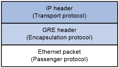
As shown in Figure 18, an EoGRE-tunneled packet includes the following parts:
· Ethernet packet—Ethernet packet to be encapsulated and transmitted.
· GRE header—Header that is added to the Ethernet packet to change the Ethernet packet to an EoGRE packet. The header includes the Protocol Type and Flags fields. GRE is called the encapsulation protocol.
· Delivery header—Header that is added to the EoGRE packet to deliver it to the tunnel end. The delivery protocol (or transport protocol) is the network layer protocol that transfers EoGRE packets.
The device supports EoGRE tunnels with IPv4 as the transport protocol. When the transport protocol is IPv4, the EoGRE tunnel mode is IPv4 EoGRE.
Figure 18 EoGRE encapsulation format
EoGRE-in-UDP encapsulation format
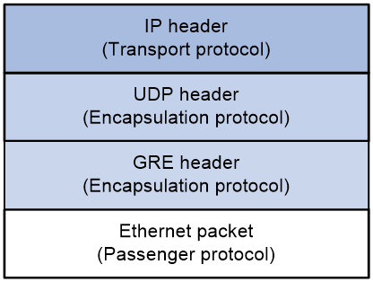
As shown in Figure 19, an EoGRE-tunneled packet in UDP encapsulation includes the following parts:
· Ethernet packet—Ethernet packet to be encapsulated and transmitted.
· GRE header—Header that is added to the Ethernet packet to change the Ethernet packet to an EoGRE packet. The header includes the Protocol Type and Flags fields and other extended fields. If the Flags field is set to 1, the EoGRE packet carries extended fields. If the Flags field is set to 0, the EoGRE packet does not carry extended fields. The extended fields include the Network Policy ID and AP MAC fields. The AP MAC can be the bridge MAC address or BSSID of the local device. GRE is called the encapsulation protocol.
· UDP header—Header that is added to the EoGRE packet to change the EoGRE packet to a UDP packet. The header includes the source and destination port numbers. The source port number is 4754. The destination port number by default is 4754, which is user configurable. UDP is called the encapsulation protocol.
· Delivery header—Header that is added to the UDP packet to deliver it to the tunnel end. The delivery protocol (or transport protocol) is the network layer protocol that transfers UDP packets.
The device supports UDP-encapsulated EoGRE tunnels with IPv4 as the transport protocol. When the transport protocol is IPv4, the EoGRE tunnel mode is IPv4 EoGRE-in-UDP.
Figure 19 EoGRE-in-UDP encapsulation format
EoGRE tunnel operating principle
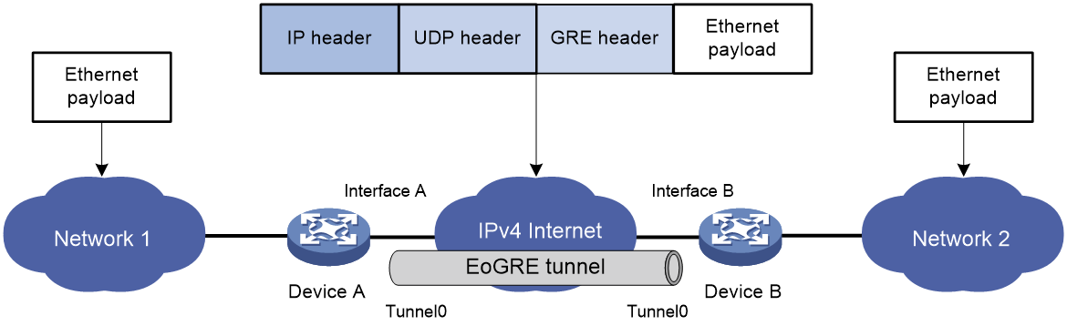
As shown in Figure 20 and Figure 21, an Ethernet packet traverses an IPv4 network through an EoGRE tunnel as follows:
1. After receiving an Ethernet packet from the interface connected to Network 1, Device A processes the packet as follows:
a. Looks up the MAC address table to identify that the Ethernet packet will be forwarded out of Interface A.
b. Searches for the EoGRE tunnel interface mapped to Interface A. In this example, EoGRE tunnel interface Tunnel 0 is mapped to the interface.
c. Submits the Ethernet packet to the outgoing interface, which is EoGRE tunnel interface Tunnel 0.
2. Upon receiving the packet, the EoGRE tunnel interface first encapsulates the packet with a GRE header. If the tunnel mode is EoGRE-in-UDP, the tunnel interface then encapsulates the packet with a UDP header. Finally, the tunnel interface encapsulates the packet with an IPv4 header. In the IPv4 header:
¡ The source address is the tunnel's source address (the IP address of Interface A on Device A).
¡ The destination address is the tunnel's destination address (the IP address of Interface B on Device B).
3. Device A looks up the routing table according to the destination address in the IPv4 header, and forwards the IPv4 packet out of the physical interface (Interface A) of the EoGRE tunnel.
4. When the IPv4 packet arrives at the EoGRE tunnel destination Device B, Device B checks the destination address. Because the destination is Device B itself and the protocol number in the IPv4 header is 6558 (represents that the inner packet is a Layer 2 packet), Device B submits the packet to EoGRE for de-encapsulation.
5. For EoGRE tunnel mode, EoGRE first removes the IPv4 header and GRE header, and then submits the Ethernet packet to Layer 2 forwarding for further processing. For EoGRE-in-UDP tunnel mode, EoGRE first removes the IPv4 header, UDP header, and GRE header, and then submits the Ethernet packet to Layer 2 forwarding for further processing.
Figure 20 Ethernet networks interconnected through an EoGRE tunnel
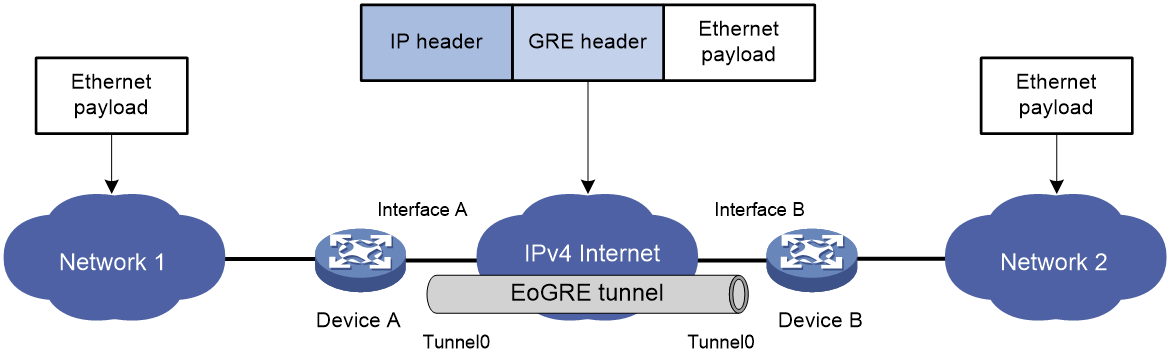
Figure 21 Ethernet networks interconnected through a UDP-encapsulated EoGRE tunnel
EoGRE application scenario
EoGRE applies to scenarios where two Layer 2 Ethernet networks communicate with each other over a Layer 3 network. As shown in Figure 22, Network 1 and Network 2 are Ethernet networks. Establish an EoGRE tunnel between Device A and Device B to interconnect Network 1 and Network 2. The two Ethernet networks can reach each other at Layer 2 over the Layer 3 backbone network.
Figure 22 EoGRE application scenario
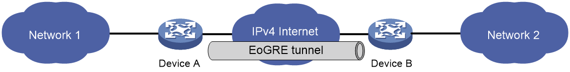
Protocols and standards
· RFC 1701, Generic Routing Encapsulation (GRE)
· RFC 1702, Generic Routing Encapsulation over IPv4 networks
· RFC 2784, Generic Routing Encapsulation (GRE)
Restrictions and guidelines: EoGRE configuration
· You must configure the tunnel source address and destination address at both ends of a tunnel. The tunnel source (or destination) address at one end must be the tunnel destination (or source) address at the other end.
· As a best practice, do not configure the same tunnel source and destination addresses for local tunnel interfaces that use the same tunnel mode.
· To ensure correct packet forwarding, identify whether the destination network of packets and the IP address of the local tunnel interface are on the same subnet. If they are not, configure a route reaching the destination network through the tunnel interface. You can configure the route by using one of the following methods:
¡ Configure a static route, using the local tunnel interface as the outgoing interface of the route.
¡ Enable a dynamic routing protocol on both the tunnel interface and the interface connecting the private network. This allows the dynamic routing protocol to establish a routing entry with the tunnel interface as the outgoing interface.
· EoGRE encapsulation and de-encapsulation can decrease the forwarding efficiency of tunnel-end devices.
Configuring an IPv4 EoGRE tunnel
Restrictions and guidelines for IPv4 EoGRE tunnel configuration
This task describes only IPv4 EoGRE tunnel required tunnel interface commands (the interface tunnel, source, and destination commands). For more tunnel interface commands, see "Configuring tunneling."
Configuring a Layer 2 VEB interface
1. Enter system view.
system-view
2. Create a Layer 2 virtual Ethernet bridge (VEB) interface and enter its view.
interface ve-bridge number
3. Configure the link type of the interface.
port link-type { access | hybrid | trunk }
By default, the link type of an interface is access.
4. Assign the VEB interface to VLANs.
¡ Access link type:
port access vlan vlan-id
By default, an interface of the access type belongs to VLAN 1
¡ Hybrid link type:
port hybrid vlan vlan-id-list { tagged | untagged }
By default, an interface of the hybrid type is an untagged member of the VLAN to which the interface belongs when its link type is access.
¡ Trunk link type:
port trunk permit vlan { vlan-id-list | all }
By default, an interface of the trunk type allows only traffic from VLAN 1 to pass through.
Configuring a Layer 3 physical Ethernet interface
1. Enter system view.
system-view
2. Enter Layer 3 physical Ethernet interface view.
interface interface-type interface-number
3. Map a VEB interface to the Layer 3 physical Ethernet interface.
map bridge ve-bridge number
By default, no VEB interface is mapped to a Layer 3 physical Ethernet interface.
Configuring an IPv4 EoGRE tunnel
1. Enter system view.
system-view
2. Create an IPv4 EoGRE tunnel interface and enter its view.
interface tunnel number mode { eogre | eogre-udp }
You must configure the same tunnel mode on both ends of a tunnel. Otherwise, packet delivery might fail.
3. Configure an IP address for the tunnel interface based on the Ethernet protocol.
For information about assigning an IPv4 address to an interface, see "Configuring IP addressing."
By default, no IP address is configured for a tunnel interface.
4. Configure a source address or source interface for the tunnel.
source { ip-address | interface-type interface-number }
By default, no source address or interface is configured for a tunnel.
If you configure a source address, the tunnel interface uses the source address as the source address of encapsulated packets.
If you configure a source interface, the tunnel interface uses the primary IP address of the source interface as the source address of encapsulated packets.
5. Configure a destination address for the tunnel.
destination ip-address
By default, no destination address is configured for a tunnel.
The destination address is the address of the physical interface that the tunnel remote end uses to receive packets from the EoGRE tunnel.
The tunnel local end uses this address as the destination address of encapsulated packets.
The tunnel destination address and the IP address of the tunnel interface must be in different subnets.
6. Map a VEB interface to the EoGRE tunnel interface.
map bridge ve-bridge number
By default, no VEB interface is mapped to an EoGRE tunnel interface.
7. (Optional.) Configure EoGRE packets to carry GRE extended fields.
eogre carry network-policy-id id-value mac-address { bridge | bssid }
By default, no GRE extended fields are configured to be carried in EoGRE packets.
8. (Optional.) Enable EoGRE keepalive, and set the keepalive interval and keepalive number.
keepalive [ interval [ times ] ]
By default, EoGRE keepalive is disabled.
EoGRE keepalive relies on NQA. Make sure NQA client is enabled on the device.
9. (Optional.) Enable EoGRE path MTU discovery.
tunnel path-mtu enable
By default, EoGRE path MTU discovery is disabled.
10. (Optional.) Set the ToS for tunneled packets.
tunnel tos tos-value
By default, the ToS of tunneled packets is 0.
11. (Optional.) Set the MTU of the tunnel interface.
mtu size
The default settings are as follows:
¡ If the tunnel interface has never been up, the MTU is 64000 bytes.
¡ If the tunnel interface is up, its MTU is identical to the outgoing interface's MTU minus the length of the tunnel headers. The outgoing interface is automatically obtained through routing table lookup based on the tunnel destination address.
Display and maintenance commands for EoGRE
Execute display commands in any view and reset commands in user view. ACs do not support the commands in this section.
|
Task |
Command |
Remarks |
|
Display information about tunnel interfaces. |
display interface [ tunnel [ number ] ] [ brief [ description | down ] ] |
For more information about the commands, see tunneling commands in Layer 3—IP Services Command Reference. |
|
Clear tunnel interface statistics. |
reset counters interface [ tunnel [ number ] ] |
For more information about this command, see tunneling commands in Layer 3—IP Services Command Reference. |
EoGRE configuration examples
Example: Configuring an IPv4 EoGRE tunnel
Network configuration
As shown in Figure 23, Router A and Router B are connected to Network 1 and Network 2, respectively. Establish an IPv4 EoGRE tunnel between Router A and Router B to interconnect Network 1 and Network 2.
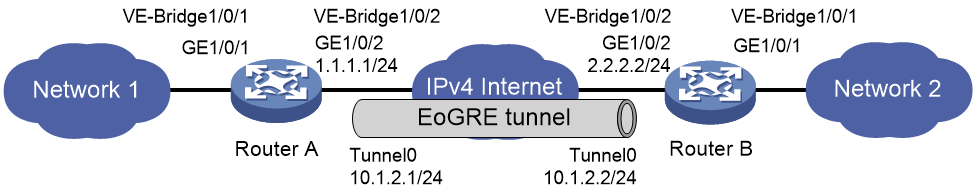
Prerequisites
Configure an IP address for each interface, and make sure Router A and Router B can reach each other.
Procedure
1. Configure Router A:
# Create Layer 2 VEB interface VE-Bridge 1/0/1.
<RouterA> system-view
[RouterA] interface ve-bridge 1/0/1
[RouterA-VE-Bridge1/0/1] quit
# Map VE-Bridge 1/0/1 to Layer 3 physical Ethernet interface GigabitEthernet 1/0/1.
[RouterA] interface gigabitethernet 1/0/1
[RouterA-GigabitEthernet1/0/1] map bridge ve-bridge 1/0/1
[RouterA-GigabitEthernet1/0/1] quit
# Create Layer 2 VEB interface VE-Bridge 1/0/2.
[RouterA] interface ve-bridge 1/0/2
[RouterA-VE-Bridge1/0/2] quit
# Create tunnel interface Tunnel 0 and set the tunnel mode to IPv4 EoGRE.
[RouterA] interface tunnel 0 mode eogre
# Configure an IP address for the tunnel interface.
[RouterA-Tunnel0] ip address 10.1.2.1 255.255.255.0
# Configure the source address of the tunnel as the IP address of GigabitEthernet 1/0/2 on Router A.
[RouterA-Tunnel0] source 1.1.1.1
# Configure the destination address of the tunnel as the IP address of GigabitEthernet 1/0/2 on Router B.
[RouterA-Tunnel0] destination 2.2.2.2
# Map VEB interface VE-Bridge 1/0/2 to the tunnel interface.
[RouterA-Tunnel0] map bridge ve-bridge 1/0/2
[RouterA-Tunnel0] quit
2. Configure Router B:
# Create Layer 2 VEB interface VE-Bridge 1/0/1.
<RouterB> system-view
[RouterB] interface ve-bridge 1/0/1
[RouterB-VE-Bridge1/0/1] quit
# Map VE-Bridge 1/0/1 to Layer 3 physical Ethernet interface GigabitEthernet 1/0/1.
[RouterB] interface gigabitethernet 1/0/1
[RouterB-GigabitEthernet1/0/1] map bridge ve-bridge 1/0/1
[RouterB-GigabitEthernet1/0/1] quit
# Create Layer 2 VEB interface VE-Bridge 1/0/2.
[RouterB] interface ve-bridge 1/0/2
[RouterB-VE-Bridge1/0/2] quit
# Create tunnel interface Tunnel 0 and set the tunnel mode to IPv4 EoGRE.
[RouterB] interface tunnel 0 mode eogre
# Configure an IP address for the tunnel interface.
[RouterB-Tunnel0] ip address 10.1.2.2 255.255.255.0
# Configure the source address of the tunnel as the IP address of GigabitEthernet 1/0/2 on Router B.
[RouterB-Tunnel0] source 2.2.2.2
# Configure the destination address of the tunnel as the IP address of GigabitEthernet 1/0/2 on Router A.
[RouterB-Tunnel0] destination 1.1.1.1
# Map VEB interface VE-Bridge 1/0/2 to the tunnel interface.
[RouterB-Tunnel0] map bridge ve-bridge 1/0/2
[RouterB-Tunnel0] quit
Verifying the configuration
# Display tunnel interface information on Router A.
[RouterA] display interface tunnel 0
Tunnel0
Current state: UP
Line protocol state: UP
Description: Tunnel0 Interface
Bandwidth: 64kbps
Maximum transmission unit: 64000
Internet address: 10.1.2.1/24 (primary)
Tunnel source 1.1.1.1, destination 2.2.2.2
Tunnel keepalive disabled
Tunnel TTL 255
Tunnel protocol/transport EoGRE/IP
Last clearing of counters: Never
Last 300 seconds input rate: 0 bytes/sec, 0 bits/sec, 0 packets/sec
Last 300 seconds output rate: 0 bytes/sec, 0 bits/sec, 0 packets/sec
Input: 0 packets, 0 bytes, 0 drops
Output: 0 packets, 0 bytes, 0 drops
# Display tunnel interface information on Router B.
[RouterB] display interface tunnel 0
Tunnel0
Current state: UP
Line protocol state: UP
Description: Tunnel0 Interface
Bandwidth: 64kbps
Maximum transmission unit: 64000
Internet address:10.1.2.2/24 (primary)
Tunnel source 2.2.2.2, destination 1.1.1.1
Tunnel keepalive disabled
Tunnel TTL 255
Tunnel protocol/transport EoGRE/IP
Last clearing of counters: Never
Last 300 seconds input rate: 0 bytes/sec, 0 bits/sec, 0 packets/sec
Last 300 seconds output rate: 0 bytes/sec, 0 bits/sec, 0 packets/sec
Input: 0 packets, 0 bytes, 0 drops
Output: 0 packets, 0 bytes, 0 drops
# Verify that Network 1 can ping Network 2 successfully. (Details not shown.)
Troubleshooting EoGRE
The key to configuring EoGRE is to keep the configuration consistent. Most faults can be located by using the debugging gre or debugging tunnel command. This section analyzes one type of fault for illustration, with the scenario shown in Figure 24.
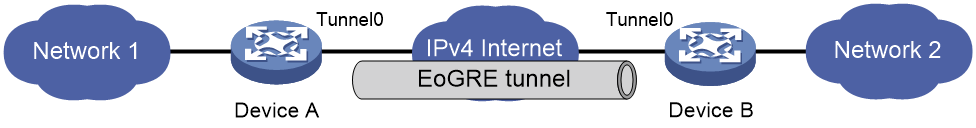
Hosts at both ends of an EoGRE tunnel cannot ping each other
Symptom
The interfaces at both ends of the tunnel are configured correctly and can ping each other, but interfaces on Network 1 and Network 2 cannot ping each other.
Solution
To resolve the issue:
1. Execute the display ip routing-table command on Device A and Device B to view whether Device A has a route over tunnel 0 to Network 2 and whether Device B has a route over tunnel 0 to Network 1.
2. If such a route does not exist, execute the ip route-static command in system view to add the route.
If the issue persists, contact H3C Support.
