- Table of Contents
- Related Documents
-
| Title | Size | Download |
|---|---|---|
| 01-POS terminal access configuration | 448.53 KB |
Configuring POS terminal access
POS application template connection modes
Cascade mode of POS access devices
Configuring caller ID prefixes
POS terminal packet statistics
POS application template handshaking
Restrictions: Hardware compatibility with POS terminal access
POS terminal access tasks at a glance
Enabling the POS access service
Configuring a POS terminal template
Configuring a TCP access POS terminal template
Configuring a flow or dial-up access POS terminal template
Configuring a POS application template
Configuring a TCP-based POS application template
Configuring a flow-based POS application template
Configuring the POS application connection keep feature
Configuring the POS application mapping table
Configuring FCM interface parameters
Configuring POS terminal packet statistics
Configuring SNMP notifications for POS terminal access
Enabling SNMP notifications for POS terminal access
Configuring the POS terminal concurrent connection threshold
Configuring the TCP concurrent transaction threshold
Configuring the alarm threshold for the low NII transaction success rate
Configuring the alarm threshold for the low E1 dialing success rate
Configuring the transaction timeout
Display and maintenance commands for POS terminal access
POS terminal access configuration examples
Example: Configuring a POS dial-up terminal (using an FCM interface) and a TCP application
Example: Configuring a POS flow terminal and a flow application
Example: Configuring a POS TCP terminal and a TCP application
Example: Configuring a POS SSL-based TCP terminal and a TCP application
Example: Configuring POS access devices in cascade mode
Example: Configuring backup FEPs (nontransparent mode)
Example: Configuring backup FEPs (transparent mode)
Configuring POS terminal access
About POS terminal access
The point of sale (POS) access service is a smart card service. It enables a POS terminal to access a bank card accounting system.
Basic concepts
POS terminal
A POS terminal refers to a POS terminal device in this chapter.
POS access device
A POS access device is a router responsible for the datagram forwarding between POS terminals and a bank front-end processor (FEP).
POS application
A POS application is a logical concept on the FEP. It identifies an application on the FEP.
POS terminal template
A POS terminal template is a logical concept on the POS access device. It stores the configuration for a POS terminal on the POS access device.
· The TCP access POS terminal template stores the port number for listening to the terminal packets on the router.
· The dial-up or flow access POS terminal template stores the router interface connected to the POS terminal, such as FCM 2/0/1.
POS application template
A POS application template stores the configuration for a POS application on the POS access device.
· When the connection mode of a POS application template is TCP, the template stores the IP and TCP port number of the FEP.
· When the connection mode of a POS application template is flow, the template stores the router interface connected to the FEP, such as Async 2/2/0.
Application mapping table
The application mapping table stores the maps between the TPDU originator and destination addresses and the application template ID. With this table, the POS access device finds the correct application template according to the TPDU originator and destination addresses in a packet received from a POS terminal. Then, the device sends the packet to the FEP.
Instance
Instance includes POS terminal instance for the POS terminal connection and POS application instance for the POS application connection. It stores the connection information dynamically. Instances inherit the parameters configuration of a template.
· For a TCP access POS terminal template, a TCP connection is referred to as an instance for the terminal template, and a terminal template can have multiple instances.
· For a dial-up or flow access POS terminal, a physical link is referred to as an instance for the terminal template, and each terminal template can have only one instance.
· For a POS application template using TCP connection mode, a TCP connection is referred to as an instance for the application template, and an application template can have multiple instances.
· For a POS application using flow connection mode, a physical link is referred to as an instance for the application template, and each application template can have only one instance.
POS terminal access modes
A POS terminal can be connected to the POS access device through dial-up access, flow access, or TCP access.
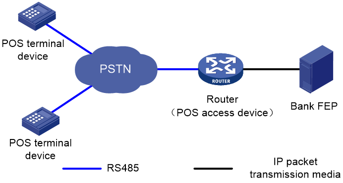
POS dial-up access
The POS dial-up access procedure uses the following process:
1. A POS terminal detects a card operation.
2. The POS terminal synchronously or asynchronously dials up with the built-in modem to establish a connection to an AM interface or FCM interface on the router (the POS access device).
The Fast Connect Modem (FCM) card is designed for fast POS dial-up access. In synchronous dial-up mode, the FCM card can establish a dial-up connection for a POS terminal in a short time.
3. The router establishes a connection to the bank FEP directly or over a WAN.
The FEP is a remote Unix/Linux server that receives packets and sends replies to the POS terminal.
4. The POS terminal accesses the bank card accounting system over the connection.
Figure 1 Network diagram
POS flow access
In POS flow access mode, the router providing POS access service is located at the commercial client side and helps all POS terminals to access the router. Figure 2 shows a typical network diagram for the POS flow access mode.
The POS flow access mode has the following advantages:
· Over 10 km (6.21 mi) connection distance (with long-line drivers).
· Fast connection rate from POS terminals to the transaction center.
· Fewer occupied communication links and reduced communication costs.
· No service queuing because each POS terminal uses a dedicated line (except networks consisting of POS concentrator and POS terminals).
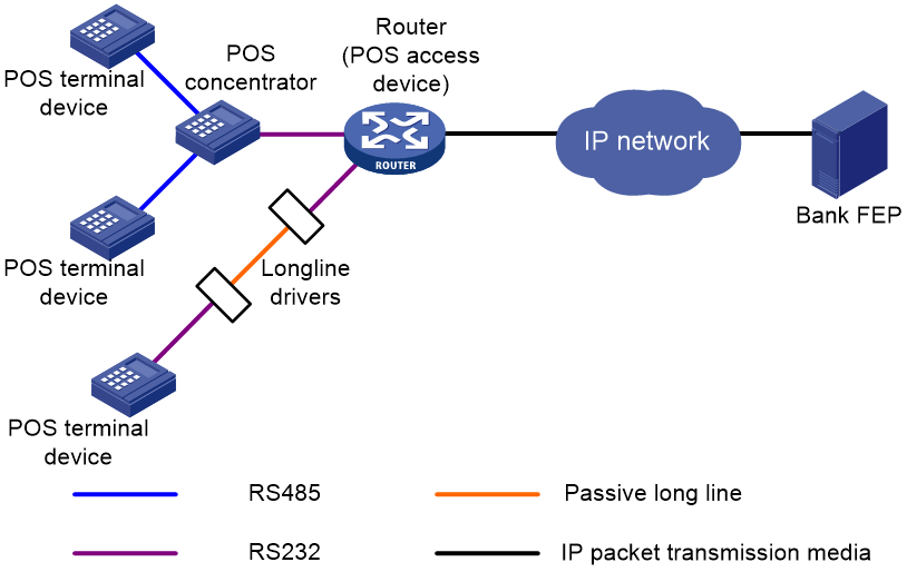
In POS flow access mode, the following methods are available for connecting a POS terminal to the router:
· Method 1—Directly connect the RS-232 interface of the POS terminal to the asynchronous interface (including the synchronous/asynchronous interface in asynchronous mode) on the router. If the connection distance is longer than 15 m (49.21 ft), you must equip each connection end with a long-line-driver to extend the connection distance.
The operating distance of a pair of passive long-line-drivers is typically about 1200 m (3937.01 ft).
· Method 2—Use multiple POS terminals and a POS concentrator. Connect the RS-232 interface of the POS concentrator to the asynchronous interface of the router.
The configurations for the egress interface of the router are the same for both methods. The second method saves interface resources.
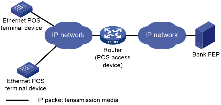
POS TCP access
This mode is applicable to Ethernet POS terminal access. A POS terminal uses its Ethernet interface to connect to the Ethernet interface of the router or of the embedded switching module. In this mode, the router requests an internal transaction number for each packet received from a POS terminal. The router uses the internal transaction number to uniquely identify a connection request and its reply:
1. The router encapsulates the internal transaction number into the packet sent to the FEP.
2. The router extracts the internal transaction number from the reply packet and uses the number to find the corresponding POS terminal.
The POS TCP access mode has the following advantages:
· Long communication distance.
· Fast connection rate from POS terminals to the transaction center.
· Reduced workload on the FEP because not all POS terminals need to establish dedicated TCP/IP connections to the FEP.
Figure 3 Network diagram for POS TCP access
POS application template connection modes
A POS application template communicates with an FEP either through a TCP connection or a flow connection, depending on the connection mode of the FEP to the POS access device.
Upon receiving a packet from a POS terminal, the POS access device processes the packets as follows:
· Encapsulates the packet according to the connection mode of the corresponding POS application template.
· Sends the resulting packet to the FEP.
TCP connection mode
In TCP connection mode, a POS application template communicates with the FEP through a TCP connection. A POS application is identified by an IP address and a port number on the FEP.
The TCP connection modes for POS application templates include permanent TCP connection mode and temporary TCP connection mode.
· Permanent TCP connection mode—The router (POS access device) uses the same TCP connection for transactions of POS terminals. In this mode, a TCP connection does not actively terminate after being established. When a POS terminal sends transaction data to the router for the first time, the router establishes a TCP connection to the FEP, and transfers the data to the FEP through the TCP connection. After the first transaction completes, the TCP connection is maintained, and is used to transfer data from subsequent transactions.
· Temporary TCP connection mode—The router uses a separate TCP connection for each transaction of POS terminals. In this mode, a TCP connection is terminated when a transaction completes, and another TCP connection will be established for a new transaction.
Flow connection mode
In flow connection mode, a POS application template is bound to an asynchronous interface through commands. One application corresponds to one asynchronous interface.
Figure 4 Network diagram of POS application connections
Cascade mode of POS access devices
You can also connect POS terminals to POS access devices in cascade mode, as shown in Figure 5.
Figure 5 Cascade mode of POS access devices
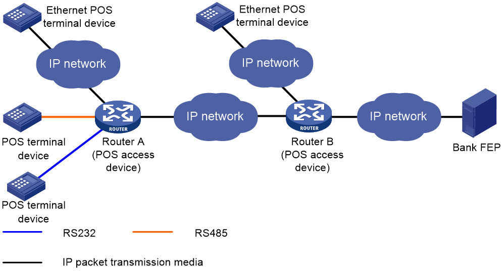
In cascade mode, packets from POS terminals to the FEP are processed by Router A and then by Router B.
· For Router A, Router B acts as the FEP using TCP connection mode.
· For Router B, Router A acts as an Ethernet POS terminal device.
To use the cascade mode:
· Establish TCP connections between Router A and Router B.
· Use temporary or permanent TCP connection mode for POS applications on Router A.
TPDU
· ID—One byte. It identifies the TPDU type. Typically, the correct packet type is 0x60. The incorrect packet type is 0x68.
· Destination Address—Two bytes, also called the Network International Identifier (NII). It indicates the destination address of the packet. Typically, the address is assigned by the transaction center to identify the FEP of a bank.
· Originator Address—Two bytes. It identifies the POS terminal device.
For the reply packet of a POS packet, the originator address and destination address in the TPDU header are reversed.
TPDU address change policy
Before the router forwards a packet from a POS terminal that uses TCP or FCM to an FEP, it changes an address in the TPDU field to a cookie. Upon receiving a response from the FEP, the router forwards the response to the corresponding POS terminal according to the cookie in the response.
FEPs require either the TPDU header's originator or destination address to change. Determine the TPDU address change policy according to the requirements of FEPs.
Router operation modes
The router may operate in transparent or nontransparent mode.
Transparent mode
POS terminals might send out packets that do not follow the TPDU format. You must use transparent mode to transmit this type of packets. Otherwise, the packets are discarded.
The transparent mode does not support the flow connection mode between a POS application template and an FEP.
The transparent mode supports FEP backup. For more information, see "FEP backup."
Nontransparent mode
In nontransparent mode, the router checks the format of each packet received from a POS terminal. If a packet does not follow the TPDU format, the router discards the packet. If a packet is valid, the router uses a POS application template based on the originator and destination addresses in the TPDU header. The router then sends the packet to an FEP according to the application template.
In nontransparent mode, the router can use the same TCP connection for multiple POS terminals to communicate with the FEP.
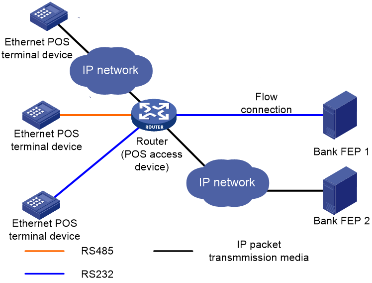
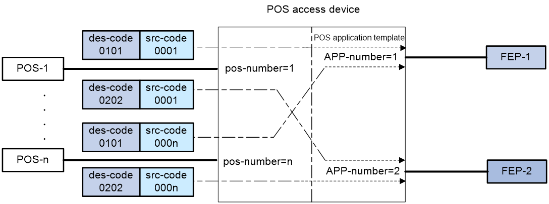
POS application mapping
The router uses the POS application mapping table to send packets from POS terminals to different FEPs. The router sends packets according to the originator address and destination address in the TPDU header of the packets.
The router must operate in nontransparent mode to implement POS application mapping. Figure 6 shows a typical example of application mapping.
Figure 6 POS application mapping (FEPs connected to the POS access device through Ethernet)
Sending caller IDs
Enable sending of caller IDs on the router for FEPs that use caller IDs in received packets to identify POS dial-up terminals. This feature is supported only for POS dial-up terminals that are connected to an AM or FCM interface on the router.
Upon receiving packets from a POS dial-up terminal connected to an AM interface, the router first sends the caller ID of the POS terminal to the FEP. After receiving a response from the FEP, the router forwards the packets to the POS terminal.
Upon receiving packets from a POS dial-up terminal connected to an FCM interface, the router adds the caller ID to the header of each packet before sending them to the FEP.
Configuring caller ID prefixes
This feature is supported only on the HMIM-1E1POS and DHMIM-1E1POS1DM interface modules.
This feature takes effect only after sending of caller IDs is enabled.
Configure this feature on the router so the FEP can identify locations of POS terminals by using the caller ID prefixes in received packets.
Sending caller IP addresses
Enable sending of caller IP addresses on the router if the FEP requires IP addresses of POS terminals. Upon receiving a packet from a POS terminal, the router adds the POS terminal's IP address to the packet header before sending the packet to the FEP. Then, the FEP can obtain the IP address of the POS terminal (the caller) from the packet.
POS terminal packet statistics
POS terminal statistics include the counts of received, sent, and error packets. The router can collect and classify the statistics based on source IP addresses, caller IDs, terminal templates, application templates, or FCM interfaces. You can view these statistics on the MIB platform.
Statistics based on source IP addresses
This method collects statistics for POS terminals using TCP access. When POS terminals transact with FEPs, the router counts the POS packets based on the terminal source IP addresses. You must specify the source IP statistical items for the statistics. The source IP or IP segments in the source IP statistical items can overlap each other or be the same. POS terminal packets that match multiple IP statistical items are counted for all the matched IP statistical items.
For example, the following are source IP statistical item definitions:
· A: Caller-IP = 192.168.0.0, mask = 255.255.0.0
· B: Caller-IP = 192.168.1.0, mask = 255.255.255.0
· C: Caller-IP = 192.167.0.0, mask = 255.255.0.0
When a POS terminal sends packets with source IP address 192.168.1.2, the packets are counted for both item A and item B.
Statistics based on caller IDs
This method collects statistics for POS terminals that do not use TCP access. When POS terminals transact with the FEPs, the router counts the packets based on the configured caller IDs. Only packets matching the caller IDs are counted.
For example, the following are caller ID definitions:
A: Caller-ID = 82770009
B: Caller-ID = 82770008
C: Caller-ID = 82770007
To be counted in B, POS terminal packets must have the caller ID 82770008.
Statistics based on terminal templates
This method collects statistics only for packets exchanged with POS terminals. The statistics include the counts for the following items:
· Received packets, sent packets, and error packets.
· Error packets due to application mapping failures.
· Discarded packets due to full buffer.
· Discarded packets due to link failures.
· Announce packets sent to POS terminals from the router.
Statistics collection for a terminal template applies to all instances that use the terminal template.
Statistics based on application templates
This method collects statistics only for packets exchanged with FEPs. The statistics include the counts for the following items:
· Received packets, sent packets, and error packets.
· Error packets due to distributing and processing failures.
· Discarded packets due to full buffer.
· Discarded packets due to link failures.
Statistics collection for an application template applies to all instances that use the application template.
Statistics based on FCM interfaces
This method collects statistics for POS terminals connected to FCM interfaces. The statistics include the counts for the following items:
· Total transactions.
· Successful transactions.
· Failed transactions due to dial-up negotiation failures.
· Disconnected transactions due to timeouts.
A transaction is regarded as successful only when an FCM interface receives data from a POS terminal and sends a reply to the terminal. If a link timeout occurs after several packets are processed successfully for a transaction, the number of successful transactions and the number of disconnected transactions each increase by one.
FEP backup
If the router cannot reach the FEP because of FEP or link failure, the ongoing transaction fails. To solve this problem, you can configure a backup FEP on the router by using the backup app command.
FEP backup is applicable only to POS TCP access. When a POS terminal launches a transaction, the router tries to establish a TCP connection with the primary or backup FEP, depending on the FEP state. If the FEP is unreachable, the router places the FEP to blocked state and starts a quiet timer. Before the timer expires, the FEP keeps in blocked state. After the timer expires, the router places the FEP to non-blocked state. You can set an individual quiet timer for each FEP.
The router selects an FEP for a transaction by following these selection rules:
· If both the primary and backup FEPs are in non-blocked state, the router initiates a connection with the primary FEP. If the connection fails, with the backup FEP.
· If only one FEP is in non-blocked state, the router initiates a connection with the FEP in non-blocked state. If the connection fails, with the other FEP.
· If both the primary and backup FEPs are in blocked state, the router initiates a connection with the primary FEP first and then with the backup FEP.
If both FEPs are unreachable, the transaction fails. If an FEP fails after a connection is successfully established with the FEP, the transaction fails, and the router does not select the other FEP for this transaction. The router selects an FEP for the next transaction by following the selection rules.
POS application template handshaking
By default, the router communicates with an FEP only when a POS terminal initiates a transaction. If the FEP is faulty, the transaction might fail or be delayed. To solve this problem, you can enable the POS application handshaking function to periodically detect the state of an FEP. This function also allows FEPs to detect the reachability of the router.
This function applies only to POS application templates using TCP connection. The router first initiates a connection to the corresponding FEP for the current application template at a specific interval. When the TCP connection is established, the router sends to the FEP a POS packet with an empty data field. The FEP does not respond to the packet.
· For an application template that uses the temporary TCP connection mode, the router periodically initiates a new connection and sends a packet over the connection. Once the packet is successfully sent, the router breaks the connection.
· For an application template that uses the permanent TCP connection mode, the router does not break the connection but uses the connection to send packets periodically at the interval.
Handshaking changes the state of the current POS application. If the POS application is in blocked state, it will switch to non-blocked state when the handshaking succeeds. If the POS application is in non-blocked state, it will switch to blocked state when the handshaking fails.
Restrictions: Hardware compatibility with POS terminal access
|
Hardware |
POS terminal access compatibility |
|
MSR810, MSR810-W, MSR810-W-DB, MSR810-LM, MSR810-W-LM, MSR810-10-PoE, MSR810-LM-HK, MSR810-W-LM-HK, MSR810-LM-CNDE-SJK, MSR810-CNDE-SJK |
No |
|
MSR810-LMS, MSR810-LUS |
No |
|
MSR810-LMS-EA, MSR810-LME |
No |
|
MSR1004S-5G |
No |
|
MSR2600-6-X1, MSR2600-10-X1, MSR2600-15-X1 |
No |
|
MSR 2630 |
Yes |
|
MSR3600-28, MSR3600-51 |
Yes |
|
MSR3600-28-SI, MSR3600-51-SI |
No |
|
MSR3600-28-X1, MSR3600-28-X1-DP, MSR3600-51-X1, MSR3600-51-X1-DP |
Yes |
|
MSR3610-I-DP, MSR3610-IE-DP, MSR3610-IE-ES, MSR3610-IE-EAD, MSR-EAD-AK770, MSR3610-I-IG, MSR3610-IE-IG |
No |
|
MSR3610-X1, MSR3610-X1-DP, MSR3610-X1-DC, MSR3610-X1-DP-DC, MSR3620-X1, MSR3640-X1 |
Yes |
|
MSR 3610, MSR 3620, MSR 3620-DP, MSR 3640, MSR 3660 |
Yes |
|
MSR3610-G, MSR3620-G |
Yes |
|
MSR3640-X1-HI |
Yes |
|
Hardware |
POS terminal access compatibility |
|
MSR810-W-WiNet, MSR810-LM-WiNet |
No |
|
MSR830-4LM-WiNet |
No |
|
MSR830-5BEI-WiNet, MSR830-6EI-WiNet, MSR830-10BEI-WiNet |
No |
|
MSR830-6BHI-WiNet, MSR830-10BHI-WiNet |
No |
|
MSR2600-6-WiNet, MSR2600-10-X1-WiNet |
No |
|
MSR2630-WiNet |
Yes |
|
MSR3600-28-WiNet |
Yes |
|
MSR3610-X1-WiNet |
Yes |
|
MSR3610-WiNet, MSR3620-10-WiNet, MSR3620-DP-WiNet, MSR3620-WiNet, MSR3660-WiNet |
Yes |
|
Hardware |
POS terminal access compatibility |
|
MSR2630-XS |
No |
|
MSR3600-28-XS |
Yes |
|
MSR3610-XS |
Yes |
|
MSR3620-XS |
Yes |
|
MSR3610-I-XS |
No |
|
MSR3610-IE-XS |
No |
|
MSR3620-X1-XS |
Yes |
|
MSR3640-XS |
Yes |
|
MSR3660-XS |
Yes |
|
Hardware |
POS terminal access compatibility |
|
MSR810-LM-GL |
No |
|
MSR810-W-LM-GL |
No |
|
MSR830-6EI-GL |
No |
|
MSR830-10EI-GL |
No |
|
MSR830-6HI-GL |
No |
|
MSR830-10HI-GL |
No |
|
MSR1004S-5G-GL |
No |
|
MSR2600-6-X1-GL |
No |
|
MSR3600-28-SI-GL |
No |
POS terminal access tasks at a glance
To configure POS terminal access, perform the following tasks:
1. Enabling the POS access service
2. Configuring a POS terminal template
3. Configuring a POS application template
4. Configuring the POS application connection keep feature
5. (Optional) Configuring the POS application mapping table
This task is required in nontransparent mode.
6. (Optional) Configuring FCM interface parameters
7. (Optional) Configuring POS terminal packet statistics
8. (Optional) Configuring SNMP notifications for POS terminal access
¡ Enabling SNMP notifications for POS terminal access
¡ Configuring the POS terminal concurrent connection threshold
¡ Configuring the TCP concurrent transaction threshold
¡ Configuring the alarm threshold for the low NII transaction success rate
¡ Configuring the alarm threshold for the low E1 dialing success rate
9. Configuring the transaction timeout
Enabling the POS access service
1. Enter system view.
system-view
2. Enable the POS access service.
posa server enable
By default, the POS terminal access service is disabled.
Configuring a POS terminal template
Configuring a TCP access POS terminal template
Restrictions and guidelines
Multiple TCP access POS terminal templates cannot use the same listening port.
Procedure
1. Enter system view.
system-view
2. (Optional.) Enable the automatic shutdown of the listening ports for TCP-based POS terminal templates.
posa auto-stop-service enable
By default, the router does not automatically shut down the listening ports for TCP-based POS terminal templates.
3. (Optional.) Configure the TPDU destination address replacement policy.
posa tpdu-replace match terminal { terminal-id | any } destination { des-code | any } to des-code
By default, the router does not replace the TPDU destination address.
4. Specify an SSL server policy for TCP-based POS terminal templates.
posa terminal ssl-server-policy policy-name
By default, no SSL server policy is specified for TCP-based POS terminal templates.
Execute this command if you specify the https or ssl keyword of the posa terminal command. The device uses the SSL server policy parameters to establish HTTPS or SSL connections with POS terminals.
5. Create a TCP access POS terminal template.
posa terminal terminal-id type tcp listen-port port [ idle-time time ] [ http | https | ssl ]
6. (Optional.) Configure a description for the POS terminal template.
posa terminal terminal-id description text
By default, a POS terminal template does not have a description.
Configuring a flow or dial-up access POS terminal template
Restrictions and guidelines
Flow access POS terminal templates can be applied to synchronous/asynchronous interfaces or asynchronous interfaces.
Dial-up access POS terminal templates can be applied to the following types of interfaces:
· Physical AM interface
· Physical FCM interface
· Channelized AM interface
A channelized AM interface is an AM interface channelized from a physical CE1/PRI interface of the PHY_E1DM or PHY_E1POSDM type.
· Channelized FCM interface
A channelized FCM interface is an FCM interface channelized from a physical CE1/PRI interface of the PHY_E1POS or PHY_E1POSDM type.
When the access interface is a synchronous/asynchronous interface, asynchronous interface, physical AM interface, or physical FCM interface
1. Enter system view.
system-view
2. (Optional.) Set FCM parameters for modem negotiation.
posa fcm { answer-time time1 | idle-time time2 | trade-time time3 } *
By default:
¡ time1 is 2000 milliseconds.
¡ time2 is 180 seconds.
¡ time3 is 12000000 milliseconds.
3. (Optional.) Set the description of the POS terminal template.
posa terminal terminal-id description text
By default, no description is set for a POS terminal template.
4. (Optional.) Configure the TPDU destination address replacement policy.
posa tpdu-replace match terminal { terminal-id | any } destination { des-code | any } to des-code
By default, the router does not replace the TPDU destination address.
5. Enter interface view.
interface interface-type interface-number
6. Specify the interface as a POS access interface.
posa bind terminal terminal-id [ app app-id ]
By default, no POS access interface is configured.
To configure a POS terminal template to operate in transparent mode, you must specify a POS application template ID by using the app app-id option. As a best practice, specify an existing POS application template. To configure a POS application template, see "Configuring a POS application template."
When the access interfaces are channelized AM interfaces or channelized FCM interfaces
1. Enter system view.
system-view
2. (Optional.) Set FCM parameters for modem negotiation.
posa fcm { answer-time time1 | idle-time time2 | trade-time time3 } *
By default:
¡ time1 is 2000 milliseconds.
¡ time2 is 180 seconds.
¡ time3 is 12000000 milliseconds.
3. (Optional.) Set the description of the POS terminal template.
posa terminal terminal-id description text
By default, no description is set for a POS terminal template.
4. (Optional.) Configure the TPDU destination address replacement policy.
posa tpdu-replace match terminal { terminal-id | any } destination { des-code | any } to des-code
By default, the router does not replace the TPDU destination address.
5. Enter interface view.
interface interface-type interface-number:setnumber
6. Configure the subinterfaces of the interface as POS access interfaces:
posa bind terminal first-terminal-id first-terminal-id [ app-list app-list ] [ reassemble ]
By default, no POS access interfaces are configured.
To configure POS terminal templates to operate in transparent mode, you must specify POS application templates by using the app-list app-list option. As a best practice, specify existing POS application templates. To configure a POS application template, see "Configuring a POS application template."
Configuring a POS application template
Configuring a TCP-based POS application template
Restrictions and guidelines
· The FEP IP address or host name must be configured for a POS application template in TCP mode.
· Specifying a source IP address or source port number of a POS application template removes all existing TCP connections that use the template. The specified source port cannot be the same as the listening port specified for a terminal template or source port specified for any other application template. If you specify a source port number that is the same as the port number for any other system process, the source port does not take effect.
· If you switch between the permanent and temporary mode, the TCP connections already established by the POS application template are terminated.
Procedure
1. Enter system view.
system-view
2. Create a POS application template and enter POS application template view.
posa app app-id type tcp
3. Specify an FEP. Choose one option as needed:
¡ Specify the IP address and port number of an FEP.
ip ip-address port port-number.
You can specify only one IP address and port number for a POS application template. Modifying the IP address or port number also removes all existing TCP connections that use this template.
¡ Specify the host name and port number of the FEP.
host host-name port port-number
You can specify only one host name and port number for a POS application template. Modifying the IP address or port number also removes all existing TCP connections that use this template.
4. Configure the TCP connection mode of the POS application template.
mode { temporary | permanent }
By default, the permanent mode is used.
When POS access devices are connected through TCP in cascade mode, specify the temporary mode for POS application templates between the POS access devices.
5. Specify a source IP address for TCP connections.
source ip ip-address
By default, no source IP address is specified.
6. Specify a source port number for TCP connections.
source port port-number
By default, no source port is specified.
7. (Optional.) Configure optional parameters of the POS application template.
¡ Configure a description for the POS application template.
description text
By default, no description is configured for the POS application template, and it is displayed as an empty string on the MIB platform.
¡ Configure the TCP keepalive parameters for the POS application template.
tcp keepalive interval interval count counts
By default, the value of interval is 2 seconds, and the value of counts is 3.
Changes to the keepalive parameters take effect immediately. When the TCP connections are terminated because of the keepalive detection mechanism, it will not trigger the switch between the primary and backup FEP if a backup application template is already specified.
¡ Specify the TCP connection timeout.
tcp linking-time time
By default, the timeout is 20 seconds.
The configuration takes effect only on TCP connections initiated after the configuration.
¡ Enable sending of caller IDs.
caller-number enable
By default, caller ID sending is disabled.
This feature is supported for POS dial-up terminals connected to AM or FCM interfaces. For a POS terminal connected to an AM interface, you must enable the modem module in TTY view to obtain the caller ID. For more information, see modem management commands in Layer 2—LAN Switching Command Reference.
¡ Configure a caller ID prefix.
posa calling-prefix string
By default, the router does not add a prefix to caller IDs in packets sent to the FEP.
This feature takes effect only after sending of caller IDs is enabled.
¡ Enable sending of caller IP addresses.
terminal-ip append
By default, caller IP address sending is disabled.
This feature is applicable only when the POS terminal access mode is TCP.
¡ Configure the TPDU address change policy.
tpdu-change { destination | source }
By default, the TPDU originator address will be changed.
In nontransparent mode, modifying the TPDU address change policy removes all permanent TCP connections that use the application template.
¡ Specify the backup POS application template.
backup app app-id
By default, no backup POS application template is specified.
If the specified application template does not exist or is not TCP type, the command can be configured but it does not take effect.
¡ Set the quiet timer.
timer quiet interval
By default, the quiet time is 600 minutes.
The change on the quite timer takes effect immediately. The new timer starts from the beginning for an FEP in blocked state.
¡ Enable the POS application template handshaking.
hello enable
By default, POS application template handshaking is disabled.
¡ Set the interval time for the handshaking packet.
timer hello interval
By default, the interval is 1 minute.
¡ Enable automatic connection to the FEP from the POS application template.
auto-connect enable
By default, the router does not automatically initiate a connection to the FEP.
This function takes effect only on POS application templates that use the permanent TCP connection mode:
¡ Set the interval between auto connections to the FEP for the POS application template.
timer auto-connect interval
By default, the interval is 10 minutes.
Configuring a flow-based POS application template
Restrictions and guidelines
You must bind a flow-based POS application template to an interface.
Procedure
1. Enter system view.
system-view
2. Create a POS application template and enter POS application template view.
posa app app-id type flow
3. (Optional.) Configure optional parameters of the POS application template.
¡ Configure a description for the POS application template.
description text
By default, no description is configured for the POS application template, and it is displayed as an empty string on the MIB platform.
¡ Configure the TPDU address change policy.
tpdu-change { destination | source }
By default, the TPDU originator address will be changed.
In nontransparent mode, modifying the TPDU address change policy removes all permanent TCP connections that use the application template.
4. Return to system view.
quit
5. Enter interface view.
interface interface-type interface-number
The interface can be an asynchronous interface, or a synchronous/asynchronous interface.
6. Bind the POS application template to the interface.
posa bind app app-id
By default, no POS application template is bound to the interface.
Configuring the POS application connection keep feature
About this task
After you configure this feature, when the IP address corresponding to the FEP hostname in the POS application template changes, the POS access device does not disconnect the current TCP connection for the POS application. Instead, it initiates a new connection immediately when it detects the disconnection through TCP keepalive. When the POS access device establishes the new TCP connection, it selects the IP address of the FEP as follows (the domain name refers to the host name of the FEP):
· If the domain name and IP address mapping saved on the DNS server is not expired, the access device selects the IP address in the mapping.
· If the domain name and IP address mapping saved on the DNS server is expired, the access device selects the IP address used to establish the last TCP connection.
Restrictions and guidelines
This feature applies only to the TCP connections between POS application templates and FEPs. Configuring this feature in system view takes effect on all the TCP connections.
Procedure
1. Enter system view.
system-view
2. Configure the POS access device to keep the TCP connection between a POS application template and an FEP when the IP address for the FEP host name changes.
posa app-connection keep
By default, this feature is not configured. When the IP address corresponding to the host name of an FEP changes, the POS access device will disconnect the POS application template's TCP connection with the FEP, and use the new IP address to establish the TCP connection between the POS application template and the FEP.
Configuring the POS application mapping table
About this task
In nontransparent mode, the router uses the POS application mapping table to send packets from POS terminals to different FEPs. The router sends packets according to the originator address and destination address in the TPDU header of the packets.
Restrictions and guidelines
· One application template can correspond to multiple mapping entries.
· The entry that has both the originator and destination addresses has the highest priority. The default entry has the lowest priority.
· The device supports up to 1024 POS application mapping entries.
· Changing the destination FEP of a mapping entry during the transaction will not remove the connection in use, but it might affect the ongoing POS transaction.
Procedure
1. Enter system view.
system-view
2. Configure a POS application mapping entry.
map { { destination des-code | source src-code } * | default } app app-id
Configuring FCM interface parameters
Restrictions and guidelines
Modify the FCM interface parameters to adapt to different telephone line environments.
Procedure
1. Enter system view.
system-view
2. Enter FCM interface view.
interface fcm { interface-number | interface-number:setnumber }
The interface can be a physical FCM interface or a channelized FCM interface.
3. Set the modem negotiation scramble-binary1 time.
negotiation scramble-binary1 scramble-binary1time
By default, the scramble-binary1 time is 250 milliseconds
4. Set the modem negotiation unscramble-binary1 time.
negotiation unscramble-binary1 unscramble-binary1time
By default, the unscramble-binary1 time is 400 milliseconds.
5. Set the modem negotiation silence time.
negotiation silence silencetime
By default, the silence time is 0 milliseconds.
6. Set the hook off delay time.
negotiation hookoff delaytime
By default, the delay time is 500 milliseconds.
7. Set the number of no-carrier-detect retries.
negotiation no-carrier-detect retry retries
By default, the retry time is 1.
8. Set the modem negotiation answer-tone threshold.
threshold answer-tone answertonetime
By default, the modem negotiation answer-tone threshold is 18 -dBm when the E1POS interface module is used and 9 -dBm when the FCM interface module is used.
9. Set the RLSD turn-off threshold.
threshold rlsdoff rlsdofftime
By default, the RLSD turn-off threshold is -48 dBm.
10. Set the RLSD turn-on threshold.
threshold rlsdon rlsdontime
By default, the RLSD turn-on threshold is -43 dBm.
11. Set the modem negotiation transmission power threshold.
threshold txpower txpowertime
By default, the transmission power threshold is -10 dBm.
Configuring POS terminal packet statistics
About this task
Perform this task to configure the router to collect POS terminal packet statistics based on source IP addresses or caller IDs.
Procedure
1. Enter system view.
system-view
2. Configuring POS terminal packet statistics.
¡ Create a source IP group for POS statistics:
posa statistics caller-ip group-id ip-address ip-mask
This command applies to only TCP access POS terminal templates.
¡ Create a caller ID for POS statistics.
posa statistics caller-id caller-number
This command applies to only dial-up access POS terminal templates.
Configuring SNMP notifications for POS terminal access
Enabling SNMP notifications for POS terminal access
About this task
This feature enables generating SNMP notifications for POS access. The generated SNMP notifications are sent to the SNMP module. The SNMP module determines how to output the notifications according to the configured output rules. For more information about SNMP notifications, see Network Management and Monitoring Configuration Guide.
You can enable or disable SNMP notifications for the following types of POS access events:
· app-state-change—POS application state change.
· e1-dial-falling—E1 dialing success rate lower than the threshold.
· fcm-connection-exceed—Number of FCM concurrent connections exceeds the threshold.
· fcm-connection-exceed—Number of FCM concurrent connections exceeds the threshold.
· fcm-link-failure—FCM link layer negotiation failure.
· fcm-physical-failure—FCM physical layer negotiation failure.
· fcm-trade-abnomal—Abnormal transaction on FCM interfaces.
· server-state-change—POS access service state change.
· tcp-connection-exceed—Number of TCP concurrent connections exceeds the threshold.
· tcp-trade-exceed—Number of TCP concurrent transactions exceeds the threshold.
The router generates SNMP notifications for tcp-trade-exceed events by using the following scheme:
a. The router generates a notification when the number of concurrent transactions on a TCP connection exceeds the threshold for the first time.
b. Before the number of concurrent transactions on that TCP connection drops below 90% the threshold, the router does not generate notifications any more.
c. After the transaction number drops below 90% the threshold, the router continues to generate a notification when the threshold is exceeded.
This scheme prevents frequent SNMP notifications in case of heavy transaction traffic.
For information about setting the TCP concurrent transactions threshold, see "Configuring the TCP concurrent transaction threshold."
· terminal-hangup—Terminal hang-up.
· trade-success-falling—NII transaction success rate lower than the threshold.
Procedure
1. Enter system view.
system-view
2. Enable SNMP notifications for POS access
snmp-agent trap enable posa [ app-state-change | e1-dial-falling | fcm-connection-exceed | fcm-link-failure | fcm-physical-failure | fcm-trade-abnomal | server-state-change | tcp-connection-exceed | tcp-trade-exceed | terminal-hangup | trade-success-falling ] *
By default, SNMP notifications for POS access are enabled globally.
Configuring the POS terminal concurrent connection threshold
About this task
You can configure the FCM or TCP concurrent connection threshold for POS terminals.
The router generates SNMP notifications for fcm-connection-exceed or tcp-connection-exceed events when the following requirements are met:
· SNMP notification is enabled for fcm-connection-exceed or tcp-connection-exceed events. For more information, see "Enabling SNMP notifications for POS terminal access."
· Number of FCM or TCP concurrent connections exceeds the configured threshold.
Connections can still be established after the FCM or TCP concurrent connections threshold is exceeded.
Procedure
1. Enter system view.
system-view
2. Configure a concurrent connection threshold for POS terminals.
posa connection-threshold terminal { fcm fcm-threshold-value | tcp tcp-threshold-value }
By default, the concurrent connection threshold is 4096 for TCP access mode and 255 for FCM dial-up access mode.
Configuring the TCP concurrent transaction threshold
About this task
After the TCP concurrent transaction threshold is set, the router discards the packets that exceed the threshold. If SNMP notification for tcp-trade-exceed is also enabled, the router generates SNMP notifications as described in "Enabling SNMP notifications for POS terminal access."
Licensing requirements
You can install licenses to increase the concurrent transaction threshold for each TCP connection supported by the device. For more information about licenses, see Fundamentals Configuration Guide.
Procedure
1. Enter system view.
system-view
2. Configure the TCP concurrent transaction threshold.
posa trade-limit tcp limit-value
By default, no limit is set to the number of concurrent transactions on a TCP connection.
Configuring the alarm threshold for the low NII transaction success rate
About this task
NII indicates the TPDU destination address of the FEP in a POS packet. The router finds the correct application template according to the TPDU destination address in a packet received from a POS terminal. Then, the device sends the packet to the FEP.
You can configure the minimum number of packet round trips for a successful NII transaction. An NII transaction is regarded as successful only when the number of packet round trips between the router and the FEP is equal to or greater than the specified value.
The NII transaction success rate is the ratio of the successful NII transactions to the total NII transactions. If SNMP notification for trade-success-falling is enabled, the router generates SNMP notifications when the NII transaction success rate drops below the threshold. For more information, see "Enabling SNMP notifications for POS terminal access."
Procedure
1. Enter system view.
system-view
2. Create a POS application template and enter POS application template view.
posa app app-id type { flow | tcp }
3. Configure the minimum number of packet round trips for a successful NII transaction.
trade-exchanges counts
By default, the minimum number of packet round trips for a successful NII transaction is 1.
4. Return to system view.
quit
5. Configure the alarm threshold for the low NII transaction success rate.
posa trade-falling-threshold threshold-value
By default, the alarm threshold for the low NII transaction success rate is 90%.
Configuring the alarm threshold for the low E1 dialing success rate
About this task
An E1POS interface can be channelized into 30 FCM subinterfaces to carry 30 simultaneous POS terminal dial-up connections.
The E1 dialing success rate is the ratio of the successful dial-ups to the total dial-ups for all FCM subinterfaces of an E1POS interface. If SNMP notification for e1-dial-falling is enabled, the router generates SNMP notifications when the E1 dialing success rate drops below the threshold. For more information, see "Enabling SNMP notifications for POS terminal access."
Procedure
1. Enter system view.
system-view
2. Configure the alarm threshold for the low E1 dialing success rate.
posa e1-dialing-falling-threshold threshold-value
By default, the alarm threshold for the low E1 dialing success rate is 90%.
Configuring the transaction timeout
About this task
Perform this task to configure the transaction timeout. The timeout timer is set when the router receives a transaction packet from a POS terminal. If the router receives no reply from the FEP before the timer expires, the transaction times out. The router discards the reply packet that is received after the timer expires.
Restrictions and guidelines
If the network condition is poor, do not configure a small transaction timeout. A small transaction timeout might cause the router to reassign the transaction number of an expired transaction to a new transaction. Then, the router treats the reply to the expired transaction as the reply to the new transaction.
Procedure
1. Enter system view.
system-view
2. Set the transaction timeout.
posa trade-timeout timeout-value
By default, the timeout time for each transaction is 240 seconds.
Display and maintenance commands for POS terminal access
Execute display commands in any view and reset commands in user view.
|
Task |
Command |
|
Display POS access statistics on FCM interfaces. |
display fcm statistics [ interface fcm { interface-number | interface-number:setnumber.subnumber } ] |
|
Display POS application template statistics. |
display posa statistics app [ app-id ] |
|
Display POS transaction statistics of a caller ID. |
display posa statistics caller-id [ caller-number ] |
|
Display POS transaction statistics of a source IP statistical item. |
display posa statistics caller-ip [ group-id ] |
|
Display POS transaction statistics of an NII. |
display posa statistics nii [ nii-id ] |
|
Display POS terminal template statistics. |
display posa statistics terminal [ terminal-id ] |
|
Display POS application template status information. |
display posa status app [ app-id ] |
|
Display POS terminal template status information. |
display posa status terminal [ terminal-id ] |
|
Display connection information for POS terminal templates. |
display posa connection terminal [ terminal-id ] |
|
Clear statistics on FCM interfaces. |
reset fcm statistics [ interface fcm { interface-number | interface-number:setnumber.subnumber } ] |
|
Clear POS transaction statistics. |
reset posa statistics [ app [ app-id ] | terminal [ terminal-id ] | nii [ nii-id ] ] |
|
Disconnect the router from POS terminals |
reset posa connection terminal { all | source-ip ip-addr1 | destination-ip ip-addr2 | destination-port port-number } |
POS terminal access configuration examples
Example: Configuring a POS dial-up terminal (using an FCM interface) and a TCP application
Network configuration
As shown in Figure 7, The POS terminal dials up to the FCM interface of the POS access device. The POS access device is connected to the FEP through Ethernet.
The POS access service has been enabled on the FEP. The listening port number is 2000.
Configure POS access on the POS access device and configure FCM interface parameters as needed, so the dialup POS terminal can access the FEP.

Procedure
1. Configure GigabitEthernet 1/0/1.
<Sysname> system-view
[Sysname] interface gigabitethernet 1/0/1
[Sysname-GigabitEthernet1/0/1] ip address 10.1.1.2 255.255.255.0
[Sysname-GigabitEthernet1/0/1] quit
2. Enable POS access service.
[Sysname] posa server enable
3. Configure the POS application template:
# Configure POS application template 1 in TCP mode.
[Sysname] posa app 1 type tcp
# Specify the IP address and port number of the FEP as 10.1.1.1 and 2000.
[Sysname-posa-app1] ip 10.1.1.1 port 2000
[Sysname-posa-app1] quit
4. Configure the POS terminal template: configure FCM 2/1/0 as the access interface of terminal template 1.
[Sysname] interface fcm 2/1/0
[Sysname–Fcm12/1/0] posa bind terminal 1
5. Configure the FCM negotiation parameters:
# Set the modem negotiation scramble-binary1 time to 200 milliseconds.
[Sysname–Fcm2/1/0] negotiation scramble-binary1 200
# Set the modem negotiation unscramble-binary1 time to 900 milliseconds.
[Sysname–Fcm2/1/0] negotiation unscramble-binary1 900
# Set the modem negotiation silence time to 100 milliseconds.
[Sysname–Fcm2/1/0] negotiation silence 100
# Set the hook off delay time to 2000 milliseconds.
[Sysname–Fcm2/1/0] negotiation hookoff 2000
# Set the no-carrier-detect retry number to 20.
[Sysname–Fcm2/1/0] negotiation no-carrier-detect retry 20
# Set the modem negotiation answer-tone threshold to -41 dBm.
[Sysname–Fcm2/1/0] threshold answer-tone 41
# Set the RLSD turn-off threshold for modem negotiation to -74 dBm.
[Sysname–Fcm2/1/0] threshold rlsdoff 74
# Set the RLSD turn-on threshold for modem negotiation to -73 dBm.
[Sysname–Fcm2/1/0] threshold rlsdon 73
# Set the modem negotiation transmission power threshold to -40 dBm.
[Sysname–Fcm2/1/0] threshold txpower 40
6. Configure a default POS application mapping entry that maps all packets to POS application template 1.
[Sysname] posa map default app 1
You can configure more POS application mapping entries based on the originator and/or destination addresses in the TPDU header as needed.
Verifying the configuration
The POS terminal device sends a POS request packet. The POS access device processes the packet and forwards it to the bank FEP. The FEP receives the request packet and responds with a reply packet. The POS terminal device receives the reply packet.
Example: Configuring a POS dial-up terminal (using an E1POS interface and the PRI protocol) and a TCP application
Network configuration
As shown in Figure 8, POS terminals connect to a PBX through telephone lines and access the router through dial up. The PBX uses an E1 line to connect to the E1POS CE1/PRI interface on the router. The PBX and the router use PRI signaling to exchange messages. The CE1/PRI interface is channelized into FCM subinterfaces. The router connects to the FEP through an Ethernet interface.
Configure POS terminal access on the router so the POS terminals can access the FEP.

Procedure
1. Configure the PRI protocol on E1POS interface E1 7/0.
<Sysname> system-view
[Sysname] controller e1 7/0
[Sysname-E1 7/0] pri-set timeslot-list 1-31
[Sysname-E1 7/0] quit
2. Configure POS terminal access:
# Enable the POS access service.
[Sysname] posa server enable
# Configure the IP address of the Ethernet interface.
[Sysname] interface ethernet 1/1
[Sysname-Ethernet1/1] ip address 10.1.1.2 255.255.255.0
[Sysname-Ethernet1/1] quit
# Configure POS application template 1 in TCP mode.
[Sysname] posa app 1 type tcp
# Set the FEP IP address to 10.1.1.1 and port number to 2000 for application template 1.
[Sysname-posa-app1] ip 10.1.1.1 port 2000
[Sysname-posa-app1] quit
# Configure the FCM subinterfaces on FCM 7/0:15 as POS access interfaces. Bind the interfaces to POS terminal templates starting from POS terminal template 1. Configure the POS terminal templates to operate in transparent mode and configure all to use POS application template 1 to transfer packets to the FEP.
[Sysname] interface fcm 7/0:15
[Sysname-Fcm7/0:15] posa bind terminal first-terminal-id 1 app-list 1:30
[Sysname–Fcm7/0:15] quit
Verifying the configuration
The POS terminal device sends a POS request packet. The POS access device processes the packet and forwards it to the bank FEP. The FEP receives the request packet and responds with a reply packet. The POS terminal device receives the reply packet.
Example: Configuring a POS flow terminal and a flow application
Network configuration
As shown in Figure 9, a POS terminal is connected to the router through a serial port. The router is connected to COM2 of the FEP through a serial port.
The POS access service has been enabled on the FEP. The FEP uses COM2 to transmit data. The POS terminal packets are destined for 01f1.
Configure POS access on the router so the POS terminal can access the FEP.

Procedure
1. Enable POS access service.
<Sysname> system-view
[Sysname] posa server enable
2. Configure the POS application template:
# Configure the application template 1 in flow mode.
[Sysname] posa app 1 type flow
[Sysname-posa-app1] quit
# Bind Async 2/2/1 to application template 1.
[Sysname] interface async 2/2/1
[Sysname-Async2/2/1] async-mode flow
[Sysname-Async2/2/1] posa bind app 1
[Sysname-Async2/2/1] quit
3. Configure the POS terminal template: bind Async 2/2/0 to POS terminal template 1.
[Sysname] interface async 2/2/0
[Sysname–Async2/2/0] async-mode flow
[Sysname–Async2/2/0] posa bind terminal 1
[Sysname–Async2/2/0] quit
4. Configure a POS application mapping entry to map packets destined for 01f1 to POS application template 1.
[Sysname] posa map destination 01f1 app 1
Verifying the configuration
The POS terminal device sends a POS request packet. The router processes the packet and forwards it to the bank FEP. The FEP receives the request packet and responds with a reply packet. The POS terminal device receives the reply packet.
Example: Configuring a POS TCP terminal and a TCP application
Network configuration
As shown in Figure 10, a POS terminal is connected to the POS access device through an Ethernet interface. The POS access device is connected to the FEP through an Ethernet interface. The POS access service has been enabled on the FEP. The listening port number is 2000.
Configure POS access on the POS access device so the POS terminal can access the FEP.

Procedure
1. Enable POS access service.
<Sysname> system-view
[Sysname] posa server enable
2. Configure the POS application template:
# Configure application template 1 in TCP mode.
[Sysname] posa app 1 type tcp
# Specify the IP address and port number of the FEP as 2.2.2.1 and 2000.
[Sysname-posa-app1] ip 2.2.2.1 port 2000
[Sysname-posa-app1] quit
3. Configure POS terminal template 1: specify the TCP access mode and configure its listening port number as 3000.
[Sysname] posa terminal 1 type tcp listen-port 3000
4. Configure a default POS application mapping entry to map all packets to application template 1.
[Sysname] posa map default app 1
Verifying the configuration
The POS terminal device sends a POS request packet. The router processes the packet and forwards it to the bank FEP. The FEP receives the request packet and responds with a reply packet. The POS terminal device receives the reply packet.
Example: Configuring a POS SSL-based TCP terminal and a TCP application
Network configuration
As shown in Figure 11, a POS terminal is connected to the POS access device through an Ethernet interface. The POS access device is connected to the FEP through an Ethernet interface. The POS access device and the POS terminal use SSL-based TCP connections for communication. The POS access service has been enabled on the FEP. The listening port number is 2000.
Configure POS access on the POS access device so the POS terminal can access the FEP.

Procedure
1. Enable POS access service.
<Sysname> system-view
[Sysname] posa server enable
2. Configure the POS application template:
# Configure application template 1 in TCP mode.
[Sysname] posa app 1 type tcp
# Specify the IP address and port number of the FEP as 2.2.2.1 and 2000.
[Sysname-posa-app1] ip 2.2.2.1 port 2000
[Sysname-posa-app1] quit
3. Configure the POS terminal template:
# Create TCP access POS terminal template 1, set the listening port number to 3000, and use SSL-based TCP connections to communicate with the POS terminal.
[Sysname] posa terminal 1 type tcp listen-port 3000 ssl
#Specify SSL server policy serverpolicy for TCP-based POS terminal templates.
[Sysname] posa terminal ssl-server-policy serverpolicy
4. Configure a default POS application mapping entry to map all packets to application template 1.
[Sysname] posa map default app 1
5. Configure an SSL server policy. For more information about configuring an SSL server policy, see Security Configuration Guide.
Verifying the configuration
The POS terminal device sends a POS request packet. The router processes the packet and forwards it to the bank FEP. The FEP receives the request packet and responds with a reply packet. The POS terminal device receives the reply packet.
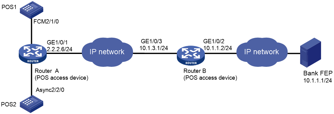
Example: Configuring POS access devices in cascade mode
Network configuration
As shown in Figure 12, POS1 is connected to Router A through dial-up. POS2 is connected to Router A through a serial port. Router A is connected to Router B through Ethernet. Router B is connected to the FEP through Ethernet.
On the FEP, the POS access service has been enabled and the listening port number is 2000.
Configure POS access on the routers so the POS terminals can access the FEP. Use only one TCP connection between the routers for all POS terminals.
Procedure
1. Configure Router A:
# Enable the POS access server.
<RouterA> system-view
[RouterA] posa server enable
# Configure the application template 1 in TCP mode.
[RouterA] posa app 1 type tcp
# Specify the IP address and port number for POS application template 1 as 10.1.3.1 and 3200.
[RouterA-posa-app1] ip 10.1.3.1 port 3200
# Configure the TCP connection mode for application template 1 as permanent. Router A will establish only one TCP connection with Router B for all transactions of POS terminals.
[RouterA-posa-app1] mode permanent
[RouterA-posa-app1] quit
# Bind FCM 2/1/0 to terminal template 1.
[RouterA] interface fcm 2/1/0
[RouterA–Fcm2/1/0] posa bind terminal 1
[RouterA–Fcm2/1/0] quit
# Bind Async 2/2/0 to terminal template 2.
[RouterA] interface async 2/2/0
[RouterA–Async2/2/0] async-mode flow
[RouterA–Async2/2/0] posa bind terminal 2
[RouterA–Async2/2/0] quit
# Configure a default application mapping entry to map all packets to application template 1.
[RouterA] posa map default app 1
2. Configure Router B:
# Enable the POS access service.
<RouterB> system-view
[RouterB] posa server enable
# Configure application template 1 in TCP mode.
[RouterB] posa app 1 type tcp
# Specify the IP address and port number of the corresponding FEP as 10.1.1.1 and 2000.
[RouterB-posa-app1] ip 10.1.1.1 port 2000
[RouterB-posa-app1] quit
# Configure terminal template 1 in TCP mode, and configure its listening port number as 3200.
[RouterB] posa terminal 1 type tcp listen-port 3200
# Configure a default application mapping entry to map all packets to application template 1.
[RouterB] posa map default app 1
Verifying the configuration
A POS terminal device sends a POS request packet. The Router A and Router B process the packet and forward it to the bank FEP. The FEP receives the request packet and responds with a reply packet. The POS terminal device receives the reply packet.
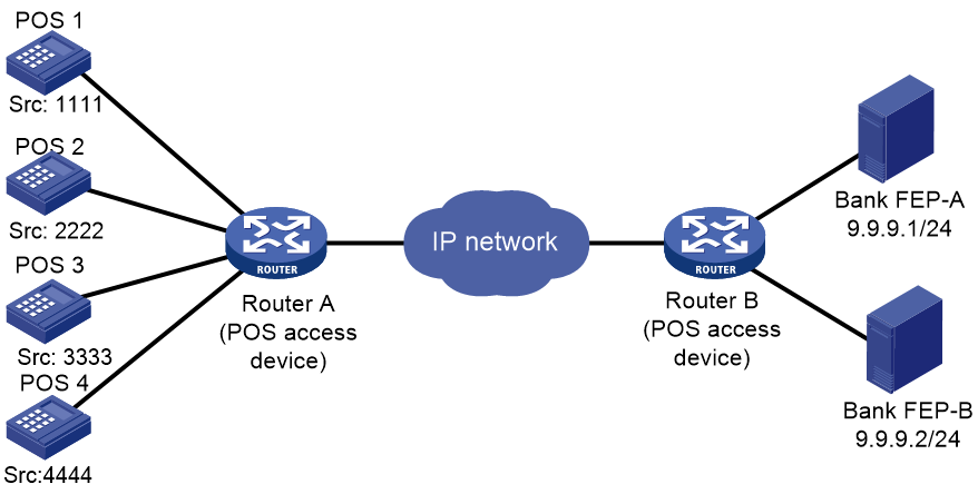
Example: Configuring backup FEPs (nontransparent mode)
Network configuration
Router A provides POS access service for the POS terminals. FEP-A is the primary FEP and FEP-B is the backup FEP for POS 1 and POS 2. FEP-B is the primary FEP and FEP-A is the backup FEP for POS 2 and POS 4.
FEPs have POS access enabled and use the listening port 2000.
Figure 13 Network diagram
Procedure
1. Enable the POS access service.
<RouterA> system-view
[RouterA] posa server enable
2. Configure application template 1:
# Configure application template 1 in TCP mode.
[RouterA] posa app 1 type tcp
# Specify FEP-A with IP address 9.9.9.1 and port number 2000 for application template 1.
[RouterA-posa-app1] ip 9.9.9.1 port 2000
# Enable the handshaking service for application template 1. Configure the handshaking interval to as minutes.
[RouterA-posa-app1] hello enable
[RouterA-posa-app1] timer hello 10
# Specify application template 2 as the backup application template.
[RouterA-posa-app1] backup app 2
# Set the quiet timer for POS application template 1 to 10 minutes.
[RouterA-posa-app1] timer quiet 10
[RouterA-posa-app1] quit
3. Configure POS application template 2:
# Configure application template 2 in TCP mode.
[RouterA] posa app 2 type tcp
# Specify FEP-B with an IP address of 9.9.9.2 and a port number of 2000 for POS application 2.
[RouterA-posa-app2] ip 9.9.9.2 port 2000
# Enable the handshaking service for application template 2. Configure the handshaking interval as 10 minutes.
[RouterA-posa-app2] hello enable
[Sysname-posa-app2] timer hello 10
# Specify application template 1 as the backup application template.
[RouterA-posa-app2] backup app 1
# Set the quiet timer for POS application template 2 to 10 minutes.
[RouterA-posa-app2] timer quiet 10
[RouterA-posa-app2] quit
4. Configure the POS terminal templates:
The POS terminals configuration varies with access modes. See the previous configuration examples.
5. Configure POS application mapping entries:
# Map packets sourced from POS 1 and POS 2 to POS application template 1.
[RouterA] posa map source 1111 app 1
[RouterA] posa map source 2222 app 1
# Map packets sourced from POS 3 and POS 4 to POS application template 2.
[RouterA] posa map source 3333 app 2
[RouterA] posa map source 4444 app 2
Verifying the configuration
Follow these steps to verify the backup FEP function:
1. Send a POS packet from the POS terminal when FEP-A is reachable.
Router A forwards the packet to FEP-A. FEP-A receives the packet and responds with a reply packet. The POS terminal device receives the reply packet successfully.
2. Disconnect FEP-A from the network, and then send a POS packet from the POS terminal.
Router A forwards the packet to FEP-B. FEP-B receives the packet and responds with a reply packet. The POS terminal device receives the reply packet successfully.
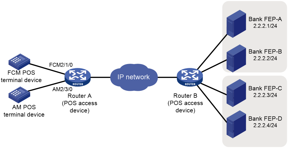
Example: Configuring backup FEPs (transparent mode)
Network configuration
In transparent mode, a pair of primary and backup FEPs can provide service for only one POS terminal.
As shown in Figure 14, FEP-A (primary FEP) and FEP-B (backup FEP) provide service for the FCM POS terminal. If FEP-A is unreachable, FEP-B is used. FEP-C (primary FEP) and FEP-D (backup FEP) provide service for the AM POS terminal. If FEP-C is unreachable, FEP-D is used.
The FEPs have POS access enabled and use the listening port 2000.
Procedure
1. Enable the POS access service.
<RouterA> system-view
[RouterA] posa server enable
2. Configure POS application template 1:
# Configure application template 1 in TCP mode.
[RouterA] posa app 1 type tcp
# Specify FEP-A with an IP address of 2.2.2.1 and a port number of 2000 for application template 1.
[RouterA-posa-app1] ip 2.2.2.1 port 2000
# Specify application template 2 as the backup application template.
[RouterA-posa-app1] backup app 2
# Set the quiet timer for POS application template 1 to 10 minutes.
[RouterA-posa-app1] timer quiet 10
[RouterA-posa-app1] quit
3. Configure POS application template 2:
# Configure application template 2 in TCP mode.
[RouterA] posa app 2 type tcp
# Specify FEP-B with an IP address of 2.2.2.2 and a port number of 2000 for POS application template 2.
[RouterA-posa-app2] ip 2.2.2.2 port 2000
[RouterA-posa-app2] quit
4. Configure POS application template 3:
# Configure application template 3 in TCP mode.
[RouterA] posa app 3 type tcp
# Specify FEP-C with an IP address of 2.2.2.3 and a port number of 2000 for POS application 3.
[RouterA-posa-app3] ip 2.2.2.3 port 2000
# Specify application template 4 as the backup application template.
[RouterA-posa-app3] backup app 4
# Set the quiet timer for POS application template 3 to 10 minutes.
[RouterA-posa-app3] timer quiet 10
[RouterA-posa-app3] quit
5. Configure POS application template 4:
# Configure application template 4 in TCP mode.
[RouterA] posa app 4 type tcp
# Specify FEP-D with an IP address of 2.2.2.4 and a port number of 2000 for POS application 4.
[RouterA-posa-app4] ip 2.2.2.4 port 2000
[RouterA-posa-app4] quit
6. Configure the AM POS terminal template:
# Configure AM 2/3/0 as the access interface of terminal template 11. Specify terminal template 11 to use POS application template 3 to transparently transport packets of the terminal.
[RouterA] interface analogmodem 2/3/0
[RouterA-Analogmodem2/3/0] posa bind terminal 11 app 3
[RouterA-Analogmodem2/3/0] quit
7. Configure the FCM POS terminal template:
# Configure FCM 2/1/0 as the access interface of terminal template 12. Specify terminal template 12 to use POS application template 1 to transparently transport packets of the terminal.
[RouterA] interface fcm 2/1/0
[RouterA-Fcm2/1/0] posa bind terminal 12 app 1
[RouterA-Fcm2/1/0] quit
Verifying the configuration
Follow these steps to verify the backup FEP function for the POS terminal that uses FCM 2/1/0:
1. Send a POS packet from the POS terminal when FEP-A is reachable.
Router A forwards the packet to FEP-A. FEP-A receives the packet and responds with a reply packet. The POS terminal device receives the reply packet successfully.
2. Disconnect FEP-A from the network, and then send a POS packet from the POS terminal.
Router A forwards the packet to FEP-B. FEP-B receives the packet and responds with a reply packet. The POS terminal device receives the reply packet successfully.
Follow these steps to verify the backup FEP function for the POS terminal that uses AM 2/3/0:
3. Send a POS packet from the POS terminal when FEP-C is reachable.
Router A forwards the packet to FEP-C. FEP-C receives the packet and responds with a reply packet. The POS terminal device receives the reply packet successfully.
4. Disconnect FEP-C from the network, and then send a POS packet from the POS terminal.
Router A forwards the packet to FEP-D. FEP-D receives the packet and responds with a reply packet. The POS terminal device receives the reply packet successfully.
