- Table of Contents
-
- 01-Fundamentals Configuration Guide
- 00-Preface
- 01-CLI configuration
- 02-RBAC configuration
- 03-Login management configuration
- 04-FTP and TFTP configuration
- 05-File system management configuration
- 06-Configuration file management configuration
- 07-Software upgrade configuration
- 08-Emergency shell configuration
- 09-Automatic configuration
- 10-Device management configuration
- 11-Tcl configuration
- 12-Python configuration
- 13-License management
- 14-RAID management configuration (routers)
- Related Documents
-
| Title | Size | Download |
|---|---|---|
| 03-Login management configuration | 440.17 KB |
Contents
Using the console port for the first device access
Restrictions and guidelines: CLI login configuration
Configuring console, AUX, or USB login
About console, AUX, and USB login
Console, AUX, and USB login configuration tasks at a glance
Configuring console, AUX, or USB login authentication
Configuring common console, AUX, or USB login settings
Configuring the device as a Telnet server
Using the device to log in to a Telnet server
Configuring the device as an SSH server
Using the device to log in to an SSH server
Logging in through a pair of modems
Configuring the device as a Telnet redirect server
Associating the Telnet redirect listening port with an IP address
Terminating a redirected Telnet connection
Display and maintenance commands for CLI login
Restrictions: Hardware compatibility with Web login
Restrictions and guidelines: Web login configuration
Web login configuration tasks at a glance
Configuring a Web login local user
Enabling Web operation logging
Display and maintenance commands for Web login
Web login configuration examples
Example: Configuring HTTP login
Example: Configuring HTTPS login
Accessing the device through SNMP
Controlling user access to the device
About login user access control
Controlling Telnet and SSH logins
Example: Controlling Telnet login
Configuring source IP-based Web login control
Example: Controlling Web login
Example: Controlling SNMP access
Configuring command authorization
Example: Configuring command authorization
Configuring command accounting
Example: Configuring command accounting
Login overview
The device supports the following types of login methods:
· CLI login—At the CLI, you can enter text commands to configure and manage the device.
To log in to the CLI, you can use one of the following methods:
¡ Connect to the console port.
¡ Connect to the AUX port.
¡ Connect to the USB port.
¡ Use Telnet.
¡ Use SSH.
¡ Use a pair of modems.
· Web login—Through the Web interface, you can configure and manage the device visually.
· SNMP access—You can run SNMP on an NMS to access the device MIB, and perform Get and Set operations to configure and manage the device.
The first time you access the device, you can only log in to the CLI through the console port, AUX port, or USB port unless the device is automatically configured at startup. After login, you can change console login parameters or configure other access methods.
In login management related descriptions, it is assumed that the device does not enter the automatic configuration process at startup.
The device supports TTY lines only when it has SIC-8AS, SIC-16AS, HMIM-8ASE, or HMIM-16ASE interface cards. For information about interface card and device compatibility, see the interface card document for the device.
Support for AUX lines, console lines, and USB lines depends on the device model. For more information, see the display line command in Fundamentals Command Reference.
The device supports the FIPS mode that complies with NIST FIPS 140-2 requirements. Support for features, commands, and parameters might differ in FIPS mode and non-FIPS mode. For more information about FIPS mode, see Security Configuration Guide.
Telnet login and HTTP-based Web login are not supported in FIPS mode.
Using the console port for the first device access
About this task
Console login is the fundamental login method.
Prerequisites
To log in through the console port, prepare a console terminal, for example, a PC. Make sure the console terminal has a terminal emulation program, such as HyperTerminal or PuTTY. For information about how to use terminal emulation programs, see the programs' user guides.
Procedure
1. Turn off the PC.
The serial ports on PCs do not support hot swapping. Before connecting a cable to or disconnecting a cable from a serial port on a PC, you must turn off the PC.
2. Find the console cable shipped with the device and connect the DB-9 female connector of the console cable to the serial port of the PC.
3. Identify the console port of the device carefully and connect the RJ-45 connector of the console cable to the console port.
|
|
IMPORTANT: To connect a PC to an operating device, first connect the PC end. To disconnect a PC from an operating device, first disconnect the device end. |
Figure 1 Connecting a terminal to the console port

4. Turn on the PC.
5. On the PC, launch the terminal emulation program, and create a connection that uses the serial port connected to the device. Set the port properties so the port properties match the following console port default settings:
¡ Bits per second—9600 bps.
¡ Flow control—None.
¡ Parity—None.
¡ Stop bits—1.
¡ Data bits—8.
6. Power on the device and press Enter as prompted.
The user view prompt appears. You can enter commands to configure or manage the device. To get help, enter a question mark (?).
Configuring CLI login
About CLI login
The device uses user lines (also called user interfaces) to manage CLI sessions and monitor user behavior. For a user line, you can configure access control settings, including the login authentication method and user roles.
User lines
User line types
The device supports the following types of user lines, and different user lines require different login methods:
· Console line—Login through the console port.
· AUX line—Login though the AUX port, typically used for dial-in access through modems.
· True type terminal (TTY) line—Login through the asynchronous serial port, Serial port in asynchronous mode or Async port.
The device uses TTY lines to manage Telnet users who use the Telnet redirect server feature to access other devices.
· USB line—Login through the USB port.
· Virtual type terminal (VTY) line—Login through Telnet or SSH.
User line numbering
A user line has an absolute number and a relative number.
An absolute number uniquely identifies a user line among all user lines. The user lines are numbered starting from 0 and incrementing by 1, in the sequence of console, TTY, AUX, VTY, and USB lines. You can use the display line command without any parameters to view supported user lines and their absolute numbers.
A relative number uniquely identifies a user line among all user lines of the same type. The number format is user line type + number. TTY lines are numbered starting from 1 and incrementing by 1. All other types of user lines are numbered starting from 0 and incrementing by 1. For example, the first VTY line is VTY 0.
User line assignment
The device assigns user lines to CLI login users depending on their login methods, as shown in "User line types." When a user logs in, the device checks the idle user lines for the login method, and assigns the lowest numbered user line to the user. For example, if VTY 0 and VTY 3 are idle when a user Telnets to the device, the device assigns VTY 0 to the user.
Each user line can be assigned only to one user at a time. If no user line is available, a CLI login attempt will be rejected.
Login authentication modes
You can configure login authentication to prevent illegal access to the device CLI.
In non-FIPS mode, the device supports the following login authentication modes:
· None—Disables authentication. This mode allows access without authentication and is insecure.
· Password—Requires password authentication. A user must provide the correct password at login.
· Scheme—Uses the AAA module to provide local or remote login authentication. A user must provide the correct username and password at login.
In FIPS mode, the device supports only the scheme authentication mode.
Different login authentication modes require different user line configurations, as shown in Table 1.
Table 1 Configuration required for different login authentication modes
|
Authentication mode |
Configuration tasks |
|
|
None |
Set the authentication mode to none. |
|
|
Password |
1. Set the authentication mode to password. 2. Set a password. |
|
|
Scheme |
1. Set the authentication mode to scheme. 2. Configure login authentication methods in ISP domain view. For more information, see Security Configuration Guide. |
|
User roles
A user is assigned user roles at login. The user roles control the commands available for the user. For more information about user roles, see "Configuring RBAC."
The device assigns user roles based on the login authentication mode and user type.
· In none or password authentication mode, the device assigns the user roles specified for the user line.
· In scheme authentication mode, the device uses the following rules to assign user roles:
¡ For an SSH login user who uses publickey or password-publickey authentication, the device assigns the user roles specified for the local device management user with the same name.
¡ For other users, the device assigns user roles according to the user role configuration of the AAA module. If the AAA server does not assign any user roles and the default user role feature is disabled, a remote AAA authentication user cannot log in.
FIPS compliance
The device supports the FIPS mode that complies with NIST FIPS 140-2 requirements. Support for features, commands, and parameters might differ in FIPS mode and non-FIPS mode. For more information about FIPS mode, see Security Configuration Guide.
Telnet login is not supported in FIPS mode.
Restrictions and guidelines: CLI login configuration
For commands that are available in both user line view and user line class view, the following rules apply:
· A setting in user line view applies only to the user line. A setting in user line class view applies to all user lines of the class.
· A non-default setting in either view takes precedence over the default setting in the other view. A non-default setting in user line view takes precedence over the non-default setting in user line class view.
· A setting in user line class view takes effect only on users who log in after the setting is made. It does not affect users who are already online when the setting is made.
Configuring console, AUX, or USB login
About console, AUX, and USB login
You can connect a terminal to the console or AUX port of the device to log in and manage the device, as shown in Figure 2 and Figure 3. For information about the login procedure, see "Using the console port for the first device access."
You can also log in to the device through the USB port by completing the following tasks:
1. Connect a bluetooth modem to the USB port of the device.
2. Use a mobile terminal to establish a connection to the bluetooth modem.
After logging in to the device, you can use the application on the mobile terminal to manage the device.
Figure 2 Logging in through the console port

Figure 3 Logging in through the console or AUX port

By default, console login is enabled and does not require authentication. The default user role is network-admin for a console user. To improve device security, configure password or scheme authentication for console login immediately after you log in to the device for the first time.
By default, AUX login is enabled and does not require authentication. The default user role is network-admin for an AUX user. To improve device security, configure password or scheme authentication for AUX login immediately after you log in to the device for the first time.
By default, USB login is enabled and does not require authentication. The default user role is network-admin for a USB user. To improve device security, configure password or scheme authentication for the USB line immediately after you log in to the device for the first time.
Restrictions and guidelines
A console, AUX, or USB login configuration change takes effect only on users who log in after the change is made. It does not affect users who are already online when the change is made.
In FIPS mode, the device supports only scheme authentication. You cannot disable authentication or configure password authentication.
Console, AUX, and USB login configuration tasks at a glance
To configure console, AUX, or USB login, perform the following tasks:
1. Configuring console, AUX, or USB login authentication
¡ Disabling authentication for console, AUX, or USB login
¡ Configuring password authentication for console, AUX, or USB login
¡ Configuring scheme authentication for console, AUX, or USB login
2. (Optional.) Configuring common console, AUX, or USB login settings
Configuring console, AUX, or USB login authentication
Disabling authentication for console, AUX, or USB login
1. Enter system view.
system-view
2. Enter console/AUX/USB line view or class view.
¡ Enter console, AUX, or USB line view.
line { aux | console | usb } first-number [ last-number ]
¡ Enter console, AUX, or USB line class view.
line class { aux | console | usb }
3. Disable authentication.
authentication-mode none
By default, authentication is disabled for console login, USB login, and AUX login.
|
|
CAUTION: When authentication is disabled, users can log in to the device through the line or line class without authentication. For security purpose, disable authentication with caution. |
4. Assign a user role.
user-role role-name
By default, a console, USB or AUX user is assigned the network-admin user role.
Configuring password authentication for console, AUX, or USB login
1. Enter system view.
system-view
2. Enter console/AUX/USB line view or class view.
¡ Enter console, AUX, or USB line view.
line { aux | console | usb } first-number [ last-number ]
¡ Enter console, AUX, or USB class view.
line class { aux | console | usb }
3. Enable password authentication.
authentication-mode password
By default, authentication is disabled for console login, USB login, and AUX login.
4. Set a password.
set authentication password { hash | simple } string
By default, no password is set.
5. Assign a user role.
user-role role-name
By default, a console, USB, or AUX user is assigned the network-admin user role.
Configuring scheme authentication for console, AUX, or USB login
1. Enter system view.
system-view
2. Enter console/AUX/USB line view or class view.
¡ Enter console, AUX, or USB line view.
line { aux | console | usb } first-number [ last-number ]
¡ Enter console, AUX, or USB line class view.
line class { aux | console | usb }
3. Enable scheme authentication.
In non-FIPS mode:
authentication-mode scheme
By default, authentication is disabled for console login, USB login, and AUX login.
In FIPS mode:
authentication-mode scheme
By default, scheme authentication is enabled.
|
|
CAUTION: When you enable scheme authentication, make sure an authentication user account is available. If no authentication user account is available, you cannot log in to the device through the line or line class at the next time. |
4. Configure user authentication parameters in ISP domain view.
To use local authentication, configure a local user and set the relevant attributes. To use remote authentication, configure a RADIUS, LDAP, or HWTACACS scheme. For more information, see AAA in Security Configuration Guide.
Configuring common console, AUX, or USB login settings
Restrictions and guidelines
Some common console, AUX, or USB login settings take effect immediately and can interrupt the current session. Use a login method different from console, AUX, or USB login to log in to the device before you change console, AUX, or USB login settings.
After you change console, AUX, or USB login settings, adjust the settings on the configuration terminal accordingly for a successful login.
Procedure
1. Enter system view.
system-view
2. Enter console/AUX/USB line view or class view.
¡ Enter console, AUX, or USB line view.
line { aux | console | usb } first-number [ last-number ]
¡ Enter console, AUX, or USB line class view.
line class { aux | console | usb }
3. Configure transmission parameters.
¡ Set the transmission rate.
speed speed-value
By default, the transmission rate is 9600 bps.
This command is not available in user line class view.
¡ Specify the parity mode.
parity { even | mark | none | odd | space }
By default, a user line does not use parity.
This command is not available in user line class view.
¡ Configure flow control.
flow-control { hardware | none | software }
flow-control hardware direction1 [ software direction2 ]
flow-control software direction1 [ hardware direction2 ]
By default, the device does not perform flow control.
This command is not available in user line class view.
¡ Specify the number of data bits for a character.
databits { 5 | 6 | 7 | 8 }
The default is 8.
This command is not available in user line class view.
|
Parameter |
Description |
|
7 |
Uses standard ASCII characters. |
|
8 |
Uses extended ASCII characters. |
|
5 and 6 |
Available only for modem dial-in. |
¡ Specify the number of stop bits for a character.
stopbits { 1 | 1.5 | 2 }
The default is 1.
Stop bits indicate the end of a character. The more the stop bits, the slower the transmission.
This command is not available in user line class view.
4. Enable stop bit setting consistency detection.
stopbit-error intolerance
By default, stop bit setting consistency detection is disabled.
This command is not available in user line class view.
5. Configure terminal attributes.
¡ Enable the terminal service.
shell
Be default, the terminal service is enabled on all user lines.
The undo shell command is not available in AUX line view.
The undo shell command is not available in console line view.
¡ Specify the terminal display type.
terminal type { ansi | vt100 }
By default, the terminal display type is ANSI.
The device supports ANSI and VT100 terminal display types. As a best practice, specify VT100 type on both the device and the configuration terminal. You can also specify the ANSI type for both sides, but a display problem might occur if a command line has more than 80 characters.
¡ Set the maximum number of lines of command output to send to the terminal at a time.
screen-length screen-length
By default, the device sends a maximum of 24 lines to the terminal at a time.
To disable pausing between screens of output, set the value to 0.
¡ Set the size for the command history buffer.
history-command max-size value
By default, the buffer size is 10. The buffer for a user line can save a maximum of 10 history commands.
¡ Set the CLI connection idle-timeout timer.
idle-timeout minutes [ seconds ]
By default, the CLI connection idle-timeout timer is 10 minutes.
If no interaction occurs between the device and the user within the idle-timeout interval, the system automatically terminates the user connection on the user line.
If you set the timeout timer to 0, the connection will not be aged out.
6. Specify the command to be automatically executed for login users on the lines.
auto-execute command command
By default, no command is specified for auto execution.
|
|
CAUTION: Use this command with caution. If this command is used on a user line, users that log in to the device through this user line might fail to configure the system. |
The device will automatically execute the specified command when a user logs in through the user line, and close the user connection after the command is executed.
If the device supports the console port, this command is available in AUX line view or AUX line class view. If the device does not support the console port, this command is not available in AUX line view or AUX line class view.
This command is not available in console line view or console line class view.
7. Configure shortcut keys.
¡ Specify the terminal session activation key.
activation-key character
By default, pressing Enter starts the terminal session.
¡ Specify the escape key.
escape-key { key-string | default }
By default, pressing Ctrl+C terminates a command.
¡ Set the user line locking key.
lock-key key-string
By default, no user line locking key is set.
Configuring Telnet login
About Telnet login
The device can act as a Telnet server to allow Telnet login, or as a Telnet client to Telnet to other devices.
Restrictions and guidelines
Telnet login is not supported in FIPS mode. For more information about FIPS mode, see Security Configuration Guide.
A Telnet login configuration change takes effect only on users who log in after the change is made. It does not affect users who are already online when the change is made.
Configuring the device as a Telnet server
Telnet server configuration tasks at a glance
To configure the device as a Telnet server, perform the following tasks:
2. Configuring Telnet login authentication
¡ Disabling authentication for Telnet login
¡ Configuring password authentication for Telnet login
¡ Configuring scheme authentication for Telnet login
3. (Optional.) Configuring common Telnet server settings
4. (Optional.) Configuring common VTY line settings
Enabling the Telnet server
1. Enter system view.
system-view
2. Enable the Telnet server.
telnet server enable
By default, the Telnet server is disabled.
Disabling authentication for Telnet login
1. Enter system view.
system-view
2. Enter VTY line view or class view.
¡ Enter VTY line view.
line vty first-number [ last-number ]
¡ Enter VTY line class view.
line class vty
3. Disable authentication.
authentication-mode none
By default, password authentication is enabled for Telnet login.
|
|
CAUTION: When authentication is disabled, users can log in to the device through the line or line class without authentication. For security purpose, disable authentication with caution. |
In VTY line view, this command is associated with the protocol inbound command. If one command has a non-default setting in VTY line view, the other command uses its setting in VTY line view, regardless of its setting in VTY line class view.
4. (Optional.) Assign a user role.
user-role role-name
By default, a VTY line user is assigned the network-operator user role.
Configuring password authentication for Telnet login
1. Enter system view.
system-view
2. Enter VTY line view or class view.
¡ Enter VTY line view.
line vty first-number [ last-number ]
¡ Enter VTY line class view.
line class vty
3. Enable password authentication.
authentication-mode password
By default, password authentication is enabled for Telnet login.
|
|
CAUTION: When you enable password authentication, you must also configure an authentication password for the line or line class. If no authentication password is configured, you cannot log in to the device through the line or line class at the next time. |
In VTY line view, this command is associated with the protocol inbound command. If one command has a non-default setting in VTY line view, the other command uses its setting in VTY line view, regardless of its setting in VTY line class view.
4. Set a password.
set authentication password { hash | simple } password
By default, no password is set.
5. (Optional.) Assign a user role.
user-role role-name
By default, a VTY line user is assigned the network-operator user role.
Configuring scheme authentication for Telnet login
1. Enter system view.
system-view
2. Enter VTY line view or class view.
¡ Enter VTY line view.
line vty first-number [ last-number ]
¡ Enter VTY line class view.
line class vty
3. Enable scheme authentication.
authentication-mode scheme
By default, password authentication is enabled for Telnet login.
|
|
CAUTION: When you enable scheme authentication, make sure an authentication user account is available. If no authentication user account is available, you cannot log in to the device through the line or line class at the next time. |
In VTY line view, this command is associated with the protocol inbound command. If one command has a non-default setting in VTY line view, the other command uses its setting in VTY line view, regardless of its setting in VTY line class view.
4. Configure user authentication parameters in ISP domain view.
To use local authentication, configure a local user and set the relevant attributes.
To use remote authentication, configure a RADIUS, LDAP, or HWTACACS scheme. For more information, see AAA in Security Configuration Guide.
Configuring common Telnet server settings
1. Enter system view.
system-view
2. Set the DSCP value for outgoing Telnet packets.
IPv4:
telnet server dscp dscp-value
IPv6:
telnet server ipv6 dscp dscp-value
By default, the DSCP value is 48.
3. Specify the Telnet service port number.
IPv4:
telnet server port port-number
IPv6:
telnet server ipv6 port port-number
By default, the Telnet service port number is 23.
4. Set the maximum number of concurrent Telnet users.
aaa session-limit telnet max-sessions
By default, the maximum number of concurrent Telnet users is 32.
Changing this setting does not affect users who are currently online. If the new limit is less than the number of online Telnet users, no additional users can Telnet in until the number drops below the new limit.
For more information about this command, see Security Command Reference.
Configuring common VTY line settings
1. Enter system view.
system-view
2. Enter VTY line view or class view.
¡ Enter VTY line view.
line vty first-number [ last-number ]
¡ Enter VTY line class view.
line class vty
3. Configure VTY terminal attributes.
¡ Enable the terminal service.
shell
By default, the terminal service is enabled on all user lines.
¡ Specify the terminal display type.
terminal type { ansi | vt100 }
By default, the terminal display type is ANSI.
¡ Set the maximum number of lines of command output to send to the terminal at a time.
screen-length screen-length
By default, the device sends a maximum of 24 lines to the terminal at a time.
To disable pausing between screens of output, set the value to 0.
¡ Set the size for the command history buffer.
history-command max-size value
By default, the buffer size is 10. The buffer for a user line can save a maximum of 10 history commands.
¡ Set the CLI connection idle-timeout timer.
idle-timeout minutes [ seconds ]
By default, the CLI connection idle-timeout timer is 10 minutes.
If no interaction occurs between the device and the user within the idle-timeout interval, the system automatically terminates the user connection on the user line.
If you set the timeout timer to 0, the connection will not be aged out.
4. Specify the supported protocols.
protocol inbound { all | pad | ssh | telnet }
By default, Telnet and SSH are supported.
A protocol change takes effect only on users who log in after the setting is made. It does not affect users who are already online when the setting is made.
In VTY line view, this command is associated with the authentication-mode command. If one command has a non-default setting in VTY line view, the other command uses its setting in VTY line view, regardless of its setting in VTY line class view.
5. Specify the command to be automatically executed for login users on the user lines.
auto-execute command command
By default, no command is specified for auto execution.
|
|
IMPORTANT: Before you execute this command and save the configuration, make sure you can access the CLI to modify the configuration through other VTY lines or AUX lines. |
For a VTY line, you can specify a command that is to be automatically executed when a user logs in. After executing the specified command, the system automatically disconnects the Telnet session.
6. Configure shortcut keys.
¡ Specify the shortcut key for terminating a task.
escape-key { character | default }
The default setting is Ctrl+C.
¡ Set the user line locking key.
lock-key key-string
By default, no user line locking key is set.
Using the device to log in to a Telnet server
About this task
You can use the device as a Telnet client to log in to a Telnet server.
Figure 4 Telnetting from the device to a Telnet server

Prerequisites
Assign an IP address to the device and obtain the IP address of the Telnet server. If the device resides on a different subnet than the Telnet server, make sure the device and the Telnet server can reach each other.
Procedure
1. Enter system view.
system-view
2. (Optional.) Specify the source IPv4 address or source interface for outgoing Telnet packets.
telnet client source { interface interface-type interface-number | ip ip-address }
By default, no source IPv4 address or source interface is specified. The device uses the primary IPv4 address of the output interface as the source address for outgoing Telnet packets.
3. Return to user view.
quit
4. Use the device to log in to a Telnet server.
IPv4:
telnet remote-host [ service-port ] [ vpn-instance vpn-instance-name ] [ source { interface interface-type interface-number | ip ip-address } ] [ dscp dscp-value ] [ escape character ]
IPv6:
telnet ipv6 remote-host [ -i interface-type interface-number ] [ port-number ] [ vpn-instance vpn-instance-name ] [ source { interface interface-type interface-number | ipv6 ipv6-address } ] [ dscp dscp-value ] [ escape character ]
Configuring SSH login
About SSH login
SSH offers a secure remote login method. By providing encryption and strong authentication, it protects devices against attacks such as IP spoofing and plaintext password interception. For more information, see Security Configuration Guide.
The device can act as an SSH server to allow Telnet login, or as an SSH client to log in to an SSH server.
Configuring the device as an SSH server
About this task
This section provides the SSH server configuration procedure used when the SSH client authentication method is password. For more information about SSH and publickey authentication configuration, see Security Configuration Guide.
Procedure
1. Enter system view.
system-view
2. Create local key pairs.
In non-FIPS mode:
public-key local create { dsa | ecdsa secp256r1 | rsa }
In FIPS mode:
public-key local create { ecdsa secp256r1 | rsa }
3. Enable the SSH server.
ssh server enable
By default, the SSH server is disabled.
4. (Optional.) Create an SSH user and specify the authentication mode.
ssh user username service-type stelnet authentication-type password
5. Enter VTY line view or class view.
¡ Enter VTY line view.
line vty first-number [ last-number ]
¡ Enter VTY line class view.
line class vty
6. Enable scheme authentication.
In non-FIPS mode:
authentication-mode scheme
By default, password authentication is enabled for VTY lines.
In VTY line view, this command is associated with the protocol inbound command. If one command has a non-default setting in VTY line view, the other command uses its setting in VTY line view, regardless of its setting in VTY line class view.
In FIPS mode:
authentication-mode scheme
By default, scheme authentication is enabled for VTY lines.
In VTY line view, this command is associated with the protocol inbound command. If one command has a non-default setting in VTY line view, the other command uses its setting in VTY line view, regardless of its setting in VTY line class view.
|
|
CAUTION: When you enable scheme authentication, make sure an authentication user account is available. If no authentication user account is available, you cannot log in to the device through the line or line class at the next time. |
7. (Optional.) Specify the protocols for the user lines to support.
In non-FIPS mode:
protocol inbound { all | pad | ssh | telnet }
By default, Telnet and SSH are supported.
A protocol change takes effect only on users who log in after the setting is made. It does not affect users who are already online when the setting is made.
In VTY line view, this command is associated with the authentication-mode command. If one command has a non-default setting in VTY line view, the other command uses its setting in VTY line view, regardless of its setting in VTY line class view.
In FIPS mode:
protocol inbound ssh
By default, SSH is supported.
A protocol change takes effect only on users who log in after the setting is made. It does not affect users who are already online when the setting is made.
In VTY line view, this command is associated with the authentication-mode command. If one command has a non-default setting in VTY line view, the other command uses its setting in VTY line view, regardless of its setting in VTY line class view.
8. (Optional.) Set the maximum number of concurrent SSH users.
aaa session-limit ssh max-sessions
By default, the maximum number of concurrent SSH users is 32.
Changing this setting does not affect users who are currently online. If the new limit is less than the number of online SSH users, no additional SSH users can log in until the number drops below the new limit.
For more information about this command, see Security Command Reference.
9. (Optional.) Configure common settings for VTY lines:
a. Return to system view.
quit
b. Configure common settings for VTY lines.
See "Configuring common VTY line settings."
Using the device to log in to an SSH server
About this task
You can use the device as an SSH client to log in to an SSH server.
Figure 5 Logging in to an SSH server from the device

Prerequisites
Assign an IP address to the device and obtain the IP address of the SSH server. If the device resides on a different subnet than the SSH server, make sure the device and the SSH server can reach each other.
Procedure
To use the device to log in to an SSH server, execute one of the following commands in user view:
IPv4:
ssh2 server
IPv6:
ssh2 ipv6 server
To work with the SSH server, you might need to specify a set of parameters. For more information, see Security Configuration Guide.
Logging in through a pair of modems
About this task
You can use a pair of modems to remotely connect to the console or AUX port of the device over PSTN when no IP network connection is available.
By default, modem dial-in is enabled and does not require authentication.
By default, modem dial-in is enabled and requires a password, but no password is configured.
Prerequisites
1. Log in to the device through any other method.
2. For the AUX line, configure a password for password authentication, or change the authentication mode and configure parameters for the new authentication mode. The configuration procedure is the same as described in "Configuring console, AUX, or USB login."
Procedure
1. Connect one modem to the serial port of the PC and another modem to the console or AUX port of the device.
2. Connect each modem to the PSTN through a telephone cable.
Figure 6 Connecting the PC to the device through modems

3. Obtain the telephone number of the device-side modem.
4. Configure the following settings on the device-side modem:
¡ AT&F—Restores the factory default.
¡ ATS0=1—Configures auto-answer on first ring.
¡ AT&D—Ignores DTR signals.
¡ AT&K0—Disables local flow control.
¡ AT&R1—Ignores RTS signals.
¡ AT&S0—Forces the DSR to remain on.
¡ ATEQ1&W—Disables the modem from returning command responses and execution results, and saves configuration.
To verify your configuration, enter AT&V to display the configuration results.
|
|
NOTE: The configuration commands and output vary by modem model. For more information, see the modem user guide. |
5. To ensure successful communication and to avoid data loss, verify that the AUX port uses the following settings:
¡ A baud rate that is lower than the transmission rate of the modem.
¡ The default parity, stop bits, and data bits settings.
In AUX line view, you can also manage modem dial-in users. For more information, see modem management in Layer 2–WAN Access Configuration Guide.
6. To ensure successful communication and to avoid data loss, verify that the console port uses the following settings:
¡ A baud rate that is lower than the transmission rate of the modem.
¡ The default parity, stop bits, and data bits settings.
7. Launch the terminal emulation program on the PC, and use the telephone number of the device-side modem to create a connection.
8. Dial the telephone number to establish a connection to the device.
For more information, see the user guide of the modem.
9. After you hear the dial tone, press Enter as prompted.
If the authentication mode is none, the user view prompt appears. If the authentication mode is password or scheme, you must enter the correct authentication information as prompted.
|
|
IMPORTANT: Do not directly close the HyperTerminal. Doing so can cause some modems to stay in use, and all subsequent dial-in attempts will fail. |
To terminate the modem connection to the device, execute the ATH command in the HyperTerminal. If the command cannot be entered, enter AT+ + +. When the word OK appears, execute the ATH command. The connection is terminated if OK is displayed. You can also terminate the connection by clicking the termination icon in the HyperTerminal window.
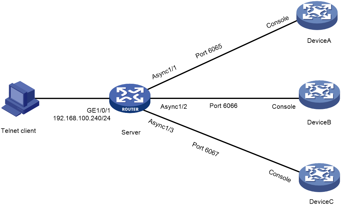
Configuring the device as a Telnet redirect server
About Telnet redirect
When the device acts as a Telnet redirect server, users can Telnet to and manage other devices without knowing the devices' IP addresses, as shown in Figure 7.
For example, a user can use the following procedure to Telnet to Device C:
1. Run a terminal emulation program on the PC and create a connection to Device C.
2. Enter 192.168.100.240 as the IP address and 6067 as the port number. Select the TCP/IP connection mode.
3. When the login prompt appears on the terminal, press Enter to enter user view.
Figure 7 Telnetting to devices through a redirect server
Restrictions and guidelines
A destination device can be connected to an AUX port of the redirect server, which can be an asynchronous port or a serial port in asynchronous mode.
For a destination device that uses its AUX port to connect to the redirect server, you must complete the following tasks if login authentication is required:
· Log in to the destination device through its console port.
· Configure login authentication and specify user roles and common attributes for AUX lines.
· Connect the AUX port of the destination device to the redirect server.
The device can redirect only one Telnet connection at a time.
Configuring Telnet redirect
1. Enter system view.
system-view
2. Enter synchronous or asynchronous serial interface view or asynchronous interface view.
¡ Enter serial interface view and configure the interface to operate in asynchronous mode.
interface serial interface-number
physical-mode async
By default, a serial interface operates in synchronous mode.
¡ Enter asynchronous interface view.
interface async interface-number
An adapter is required to connect the interface to the destination device.
3. Configure interface attributes.
¡ Set the operating mode to flow mode.
async-mode flow
By default, an asynchronous serial interface operates in protocol mode.
¡ (Optional.) Disable level detection.
undo detect dsr-dtr
By default, level detection is enabled.
Whether this command is required depends on the destination device.
4. Return to system view.
quit
5. Enter AUX or TTY line view.
line { first-number1 [ last-number1 ] | { aux | tty } first-number2 [ last-number2 ] }
6. Configure user line attributes.
¡ Set the transmission rate.
speed speed-value
By default, the transmission rate is 9600 bps.
The user line must use the same transmission rate as the destination device.
¡ Enable stop bit setting consistency detection.
stopbit-error intolerance
By default, stop bit setting consistency detection is disabled.
As a best practice, verify that the user line uses the same number of stop bits as the destination device before enabling Telnet redirect.
¡ Specify the number of stop bits.
stopbits { 1 | 1.5 | 2 }
By default, the number of stop bits is 1.
The user line must use the same number of stop bits as the destination device. Before enabling Telnet redirect, enable stop bit setting consistency detection.
7. Enable Telnet redirect.
redirect enable
By default, Telnet redirect is disabled.
8. Disable the terminal service.
undo shell
By default, the terminal service is enabled on all user lines.
9. (Optional.) Configure redirect parameters.
¡ Specify a Telnet redirect listening port.
redirect listen-port port-number
By default, the listening port number is the absolute user line number plus 2000.
¡ Set the idle-timeout timer for the redirected connection.
redirect timeout time
The default idle-timeout timer is 360 seconds.
10. (Optional.) Enable the passthrough packet redirect mode.
redirect passthrough
By default, the Telnet redirect server processes packets as dictated by the standard Telnet protocol before sending the packets to the destination device.
Execute this command if the Telnet user and destination device are not using the standard Telnet protocol. In passthrough mode, the Telnet redirect server forwards packets without processing the packets.
11. (Optional.) Disable Telnet option negotiation for the redirected connection.
redirect refuse-negotiation
By default, Telnet option negotiation is enabled for the redirected connection.
Execute this command if the destination device does not require a Telnet option negotiation.
Associating the Telnet redirect listening port with an IP address
1. Enter system view.
system-view
2. (Optional.) Associate the Telnet redirect listening port with an IP address.
ip alias ip-address port-number
By default, a Telnet redirect listening port is not associated with an IP address.
Terminating a redirected Telnet connection
1. Enter AUX or TTY line view.
line { first-number1 [ last-number1 ] | { aux | tty } first-number2 [ last-number2 ] }
2. Manually terminate the redirected Telnet connection.
redirect disconnect
|
|
CAUTION: Manually terminating a redirected Telnet connection logs out the user of the redirected Telnet connection. |
Display and maintenance commands for CLI login
Execute display commands in any view.
|
Task |
Command |
Remarks |
|
Display user line information. |
display line [ num1 | { aux | console | tty | usb | vty } num2 ] [ summary ] |
N/A |
|
Display the packet source setting for the Telnet client. |
display telnet client |
N/A |
|
Display online CLI users. |
display users [ all ] |
N/A |
|
Release a user line. |
free line { num1 | { aux | console | tty | usb | vty } num2 } |
Multiple users can log in to the device to simultaneously configure the device. When necessary, you can execute this command to release some connections. You cannot use this command to release the connection you are using or a redirected Telnet connection. This command is available in user view. |
|
Lock the current user line and set the password for unlocking the line. |
lock |
By default, the system does not lock any user lines. This command is not supported in FIPS mode. This command is available in user view. |
|
Lock the current user line and enable unlocking authentication. |
lock reauthentication |
By default, the system does not lock any user lines or initiate reauthentication. To unlock the locked user line, you must press Enter and provide the login password to pass reauthentication. This command is available in any view. |
|
Send messages to user lines. |
send { all | num1 | { aux | console | tty | usb | vty } num2 } |
This command is available in user view. |
Configuring Web login
About Web login
The device provides a built-in Web server that supports HTTP 1.0, HTTP 1.1, and HTTPS. You can use a Web browser to log in to and configure the device.
HTTPS uses SSL to ensure the integrity and security of data exchanged between the client and the server, and is more secure than HTTP. You can define a certificate-based access control policy to allow only legal clients to access the Web interface.
|
|
IMPORTANT: On a PC, a Web browser allows only one user to log in to the device. If multiple users use the same Web browser to log in to the device, the most recent login takes effect. |
Restrictions: Hardware compatibility with Web login
|
Hardware |
Web login compatibility |
|
MSR810, MSR810-W, MSR810-W-DB, MSR810-LM, MSR810-W-LM, MSR810-10-PoE, MSR810-LM-HK, MSR810-W-LM-HK, MSR810-LM-CNDE-SJK, MSR810-CNDE-SJK |
Yes |
|
MSR810-LMS, MSR810-LUS |
No |
|
MSR810-LMS-EA, MSR810-LME |
No |
|
MSR1004S-5G |
Yes |
|
MSR2600-6-X1, MSR2600-10-X1, MSR2600-15-X1 |
Yes |
|
MSR 2630 |
Yes |
|
MSR3600-28, MSR3600-51 |
Yes |
|
MSR3600-28-SI, MSR3600-51-SI |
No |
|
MSR3600-28-X1, MSR3600-28-X1-DP, MSR3600-51-X1, MSR3600-51-X1-DP |
Yes |
|
MSR3610-I-DP, MSR3610-IE-DP, MSR3610-IE-ES, MSR3610-IE-EAD, MSR-EAD-AK770, MSR3610-I-IG, MSR3610-IE-IG |
Yes |
|
MSR3610-X1, MSR3610-X1-DP, MSR3610-X1-DC, MSR3610-X1-DP-DC, MSR3620-X1, MSR3640-X1 |
Yes |
|
MSR 3610, MSR 3620, MSR 3620-DP, MSR 3640, MSR 3660 |
Yes |
|
MSR3610-G, MSR3620-G |
Yes |
|
MSR3640-X1-HI |
Yes |
|
Hardware |
Web login compatibility |
|
MSR810-W-WiNet, MSR810-LM-WiNet |
Yes |
|
MSR830-4LM-WiNet |
Yes |
|
MSR830-5BEI-WiNet, MSR830-6EI-WiNet, MSR830-10BEI-WiNet |
Yes |
|
MSR830-6BHI-WiNet, MSR830-10BHI-WiNet |
Yes |
|
MSR2600-6-WiNet, MSR2600-10-X1-WiNet |
Yes |
|
MSR2630-WiNet |
Yes |
|
MSR3600-28-WiNet |
Yes |
|
MSR3610-X1-WiNet |
Yes |
|
MSR3610-WiNet, MSR3620-10-WiNet, MSR3620-DP-WiNet, MSR3620-WiNet, MSR3660-WiNet |
Yes |
|
Hardware |
Web login compatibility |
|
MSR2630-XS |
Yes |
|
MSR3600-28-XS |
Yes |
|
MSR3610-XS |
Yes |
|
MSR3620-XS |
Yes |
|
MSR3610-I-XS |
Yes |
|
MSR3610-IE-XS |
Yes |
|
MSR3620-X1-XS |
Yes |
|
MSR3640-XS |
Yes |
|
MSR3660-XS |
Yes |
|
Hardware |
Web login compatibility |
|
MSR810-LM-GL |
Yes |
|
MSR810-W-LM-GL |
Yes |
|
MSR830-6EI-GL |
Yes |
|
MSR830-10EI-GL |
Yes |
|
MSR830-6HI-GL |
Yes |
|
MSR830-10HI-GL |
Yes |
|
MSR1004S-5G-GL |
Yes |
|
MSR2600-6-X1-GL |
Yes |
|
MSR3600-28-SI-GL |
No |
FIPS compliance
The device supports the FIPS mode that complies with NIST FIPS 140-2 requirements. Support for features, commands, and parameters might differ in FIPS mode and non-FIPS mode. For more information about FIPS mode, see Security Configuration Guide.
HTTP is not supported in FIPS mode.
Restrictions and guidelines: Web login configuration
To improve device security, the system automatically enables the HTTPS service when you enable the HTTP service. When the HTTP service is enabled, you cannot disable the HTTPS service.
The device supports configuration and management from both the Web interface and CLI. You can configure all features for the device through CLI login, but can configure only some features through Web login. These two configuration methods cannot be mixed.
Web login configuration tasks at a glance
To configure Web login, perform the following tasks:
1. Configuring Web login
2. Configuring a Web login local user
4. Enabling Web operation logging
Prerequisites for Web login
Before logging in to the Web interface of the device, log in to the device by using any other method and assign an IP address to the device. Make sure the configuration terminal and the device can communicate over the IP network.
Configuring HTTP login
1. (Optional.) Specify a fixed verification code for Web login.
web captcha verification-code
By default, no fixed verification code is specified. A Web user must enter the verification code displayed on the login page at login.
Execute this command in user view.
2. Enter system view.
system-view
3. Enable the HTTP service.
ip http enable
By default, the HTTP service is disabled.
4. (Optional.) Specify the HTTP service port number.
ip http port port-number
The default HTTP service port number is 80.
5. (Optional.) Specify the HTTP methods to be added to the reply to an OPTIONS request.
http method { delete | get | head | options | post | put } *
By default, no HTTP methods are specified.
Configuring HTTPS login
About this task
The device supports the following HTTPS login modes:
· Simplified mode—The device uses a self-signed certificate (a certificate that is generated and signed by the device itself) and the default SSL settings. The device operates in simplified mode after you enable HTTPS service on the device.
· Secure mode—The device uses a certificate signed by a CA and a set of user-defined security protection settings to ensure security. For the device to operate in secure mode, you must perform the following tasks:
¡ Enable HTTPS service on the device.
¡ Specify an SSL server policy for the service.
¡ Configure PKI domain-related parameters.
Simplified mode is easy to configure but it is insecure. Secure mode is secure but it is complicated to configure.
For more information about SSL and PKI, see Security Configuration Guide.
Restrictions and guidelines
· If the HTTPS service and the SSL VPN service use the same port number, they must use the same SSL server policy. If they use different SSL server policies, only one of them can be enabled.
To modify the SSL server policy used by both the HTTPS service and the SSL VPN service, you must perform the following tasks:
a. Disable the two services before you modify the SSL server policy.
b. Enable the two services again after the modification.
If you fail to complete the required tasks, the new settings do not take effect.
· To associate a different SSL server policy with the HTTPS service, you must perform the following tasks:
a. Disable the HTTP service and HTTPS service before you associate the new SSL server policy.
b. Enable the HTTP service and HTTPS service again after the association.
If you fail to complete the required tasks, the new SSL server policy does not take effect.
· For the HTTP service to use its self-signed certificate after you associate an SSL server policy with the HTTPS service, you must follow these steps:
a. Disable the HTTP service and HTTPS service.
b. Execute the undo ip https ssl-server-policy command to remove the existing SSL server policy association.
c. Enable the HTTP service and HTTPS service again.
· Enabling the HTTPS service triggers the SSL handshake negotiation process.
¡ If the device has a local certificate, the SSL handshake negotiation succeeds and the HTTPS service starts up.
¡ If the device does not have a local certificate, the certificate application process starts. Because the certificate application process takes a long time, the SSL handshake negotiation might fail and the HTTPS service might not be started. To solve the problem, execute the ip https enable command again until the HTTPS service is enabled.
· To use a certificate-based access control policy to control HTTPS access, you must perform the following tasks:
¡ Execute the client-verify enable command in the SSL server policy that is associated with the HTTPS service.
¡ Configure a minimum of one permit rule in the certificate-based access control policy.
If you fail to complete the required tasks, HTTPS clients cannot log in.
Procedure
1. (Optional.) Specify a fixed verification code for Web login.
web captcha verification-code
By default, no fixed verification code is configured. A Web user must enter the verification code displayed on the login page at login.
2. Enter system view.
system-view
3. (Optional.) Apply policies to the HTTPS service.
¡ Apply an SSL server policy.
ip https ssl-server-policy policy-name
By default, no SSL server policy is associated. The HTTP service uses a self-signed certificate.
¡ Apply a certificate-based access control policy to control HTTPS access.
ip https certificate access-control-policy policy-name
By default, no certificate-based access control policy is applied.
For more information about certificate-based access control policies, see PKI in Security Configuration Guide.
4. Enable the HTTPS service.
ip https enable
By default, the HTTPS service is disabled.
5. (Optional.) Specify the HTTPS service port number.
ip https port port-number
The default HTTPS service port number is 443.
6. (Optional.) Set the authentication and authorization mode for HTTPS login.
web https-authorization mode { auto | certificate | certificate-manual | manual }
By default, manual mode is used for HTTPS login authentication and authorization.
7. (Optional.) Specify the certificate field to be used as the username for certificate-based authentication.
web https-authorization username { cn | email-prefix | oid oid-value }
By default, the CN field in the certificate is used as the username for certificate-based authentication.
Configuring a Web login local user
1. Enter system view.
system-view
2. Create a local user and enter local user view.
local-user user-name [ class manage ]
3. (Optional.) Configure a password for the local user.
In non-FIPS mode:
password [ { hash | simple } password ]
By default, no password is configured for a local user. The local user can pass authentication after entering the correct username and passing attribute checks.
In FIPS mode:
password
By default, no password is configured for a local user. The local user cannot pass authentication.
4. Configure user attributes.
¡ Assign a user role to the local user.
authorization-attribute user-role user-role
The default user role is network-operator for a Web user.
¡ Specify the service type for the local user.
service-type { http | https }
By default, no service type is specified for a local user.
Managing Web connections
Setting the Web connection idle-timeout timer
1. Enter system view.
system-view
2. Set the Web connection idle-timeout timer.
web idle-timeout minutes
By default, the Web connection idle-timeout timer is 10 minutes.
Specifying the maximum number of online HTTP or HTTPS users
1. Enter system view.
system-view
2. Specify the maximum number of online HTTP or HTTPS users.
aaa session-limit { http | https } max-sessions
By default, the device supports a maximum number of 32 online HTTP users and 32 online HTTPS users.
Changing this setting does not affect users who are currently online. If the new setting is less than the number of online HTTP or HTTPS users, no additional HTTP or HTTPS users can log in until the number drops below the new limit. For more information about this command, see Security Command Reference.
Logging off Web users
To log off Web users, execute the following command in user view:
free web users { all | user-id user-id | user-name user-name }
Enabling Web operation logging
1. Enter system view.
system-view
2. Enable Web operation logging.
webui log enable
By default, Web operation logging is disabled.
Display and maintenance commands for Web login
Execute display commands in any view and the free web users command in user view.
|
Task |
Command |
|
Display HTTP service configuration and status information. |
display ip http |
|
Display HTTPS service configuration and status information. |
display ip https |
|
Display Web interface navigation tree information. |
display web menu [ chinese ] |
|
Display online Web users. |
display web users |
|
Log off online Web users. |
free web users { all | user-id user-id | user-name user-name } |
Web login configuration examples
Example: Configuring HTTP login
Network configuration
As shown in Figure 8, the PC and the device can communicate over the IP network.
Configure the device to allow the PC to log in by using HTTP.

Procedure
# Create a local user named admin. Set the password to hello12345, the service type to HTTP, and the user role to network-admin.
<Sysname> system-view
[Sysname] local-user admin
[Sysname-luser-manage-admin] service-type http
[Sysname-luser-manage-admin] authorization-attribute user-role network-admin
[Sysname-luser-manage-admin] password simple hello12345
[Sysname-luser-manage-admin] quit
# Enable HTTP.
[Sysname] ip http enable
Verifying the configuration
1. On the PC, run a Web browser and enter the IP address of the device in the address bar.
2. On the login page, enter the username, password, and verification code. Select English and click Login.
After you pass authentication, the homepage appears and you can configure the device.
Example: Configuring HTTPS login
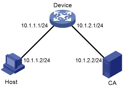
Network configuration
As shown in Figure 9, the host, device, and CA can communicate over the IP network.
Perform the following tasks to allow only authorized users to access the device's Web interface:
· Configure the device as the HTTPS server and request a certificate for the device.
· Configure the host as the HTTPS client and request a certificate for the host.
Procedure
In this example, the CA runs Windows Server and has the SCEP add-on installed.
1. Configure the device (HTTPS server):
# Create PKI entity en and set entity parameters.
<Device> system-view
[Device] pki entity en
[Device-pki-entity-en] common-name http-server1
[Device-pki-entity-en] fqdn ssl.security.com
[Device-pki-entity-en] quit
# Create PKI domain 1 and set domain parameters.
[Device] pki domain 1
[Device-pki-domain-1] ca identifier new-ca
[Device-pki-domain-1] certificate request url http://10.1.2.2/certsrv/mscep/mscep.dll
[Device-pki-domain-1] certificate request from ra
[Device-pki-domain-1] certificate request entity en
# Configure the PKI domain to use the 1024-bit long RSA key pair hostkey for both signing and encryption.
[Device-pki-domain-1] public-key rsa general name hostkey length 1024
[Device-pki-domain-1] quit
# Create RSA local key pairs.
[Device] public-key local create rsa
# Retrieve the CA certificate.
[Device] pki retrieve-certificate domain 1 ca
# Configure the device to request a local certificate through SCEP.
[Device] pki request-certificate domain 1
# Create SSL server policy myssl. Specify PKI domain 1 for the SSL server policy, and enable certificate-based SSL client authentication.
[Device] ssl server-policy myssl
[Device-ssl-server-policy-myssl] pki-domain 1
[Device-ssl-server-policy-myssl] client-verify enable
[Device-ssl-server-policy-myssl] quit
# Create certificate attribute group mygroup1. Configure a certificate attribute rule that matches statements with the new-ca string in the distinguished name of the subject name.
[Device] pki certificate attribute-group mygroup1
[Device-pki-cert-attribute-group-mygroup1] attribute 1 issuer-name dn ctn new-ca
[Device-pki-cert-attribute-group-mygroup1] quit
# Create certificate-based access control policy myacp. Configure a certificate access control rule that uses the matching criteria in certificate attribute group mygroup1.
[Device] pki certificate access-control-policy myacp
[Device-pki-cert-acp-myacp] rule 1 permit mygroup1
[Device-pki-cert-acp-myacp] quit
# Associate SSL server policy myssl with the HTTPS service.
[Device] ip https ssl-server-policy myssl
# Use certificate-based access control policy myacp to control HTTPS access.
[Device] ip https certificate access-control-policy myacp
# Enable the HTTPS service.
[Device] ip https enable
# Create local user usera. Set the password to hello12345, the service type to HTTPS, and the user role to network-admin.
[Device] local-user usera
[Device-luser-usera] password simple hello12345
[Device-luser-usera] service-type https
[Device-luser-usera] authorization-attribute user-role network-admin
2. Configure the host (HTTPS client):
# On the host, run a Web browser and enter http://10.1.2.2/certsrv in the address bar.
# Request a certificate for the host as prompted.
Verifying the configuration
1. On the host, enter https://10.1.1.1 in the Web browser's address bar, and select the certificate issued by new-ca.
2. When the Web login page appears, enter the username usera and password hello12345 to log in to the Web interface.
For more information about PKI and SSL configuration commands and the public-key local create rsa command, see Security Command Reference.
Accessing the device through SNMP
You can run SNMP on an NMS to access the device MIB and perform Get and Set operations to configure and manage the device.

For more information about SNMP, see Network Management and Monitoring Configuration Guide.
Controlling user access to the device
About login user access control
Use ACLs to prevent unauthorized access, and configure command authorization and accounting to monitor and control user behavior.
To control user access, specify an ACL that has rules so only users permitted by the ACL can access the device.
· If no ACL is applied, all users can access the device.
· If the ACL for Web user access control does not exist or does not have rules, all Web users can access the device.
· If the ACL for Telnet, SSH, or SNMP access control does not exist or does not have rules, no Telnet, SSH, or SNMP users can access the device.
For more information about ACLs, see ACL and QoS Configuration Guide.
FIPS compliance
The device supports the FIPS mode that complies with NIST FIPS 140-2 requirements. Support for features, commands, and parameters might differ in FIPS mode and non-FIPS mode. For more information about FIPS mode, see Security Configuration Guide.
Telnet and HTTP are not supported in FIPS mode.
Controlling Telnet and SSH logins
Controlling Telnet logins
1. Enter system view.
system-view
2. Apply an ACL to control Telnet logins.
IPv4:
telnet server acl [ mac ] acl-number
IPv6:
telnet server ipv6 acl { ipv6 | mac } acl-number
By default, no ACL is used to control Telnet logins.
3. (Optional.) Enable logging for Telnet login attempts that are denied by the Telnet login control ACL.
telnet server acl-deny-log enable
By default, logging is disabled for Telnet login attempts that are denied by the Telnet login control ACL.
Controlling SSH logins
1. Enter system view.
system-view
2. Apply an ACL to control SSH logins.
IPv4:
ssh server acl { advanced-acl-number | basic-acl-number | mac mac-acl-number }
IPv6:
ssh server ipv6 acl { ipv6 { advanced-acl-number | basic-acl-number } | mac mac-acl-number }
By default, no ACL is used to control SSH logins.
3. (Optional.) Enable logging for SSH login attempts that are denied by the SSH login control ACL.
ssh server acl-deny-log enable
By default, logging is disabled for SSH login attempts that are denied by the SSH login control ACL.
For more information about ssh commands, see SSH in Security Command Reference.
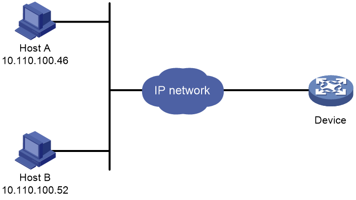
Example: Controlling Telnet login
Network configuration
As shown in Figure 11, the device is a Telnet server.
Configure the device to permit only Telnet packets sourced from Host A and Host B.
Procedure
# Configure an ACL to permit packets sourced from Host A and Host B.
<Sysname> system-view
[Sysname] acl basic 2000 match-order config
[Sysname-acl-ipv4-basic-2000] rule 1 permit source 10.110.100.52 0
[Sysname-acl-ipv4-basic-2000] rule 2 permit source 10.110.100.46 0
[Sysname-acl-ipv4-basic-2000] quit
# Apply the ACL to filter Telnet logins.
[Sysname] telnet server acl 2000
Controlling Web logins
Configuring source IP-based Web login control
1. Enter system view.
system-view
2. Apply a basic ACL to control Web logins.
¡ Control HTTP logins.
ip http acl [ ipv6 ] [ advanced ] { acl-number | name acl-name }
ip http acl mac { acl-number | name acl-name }
¡ Control HTTPS logins.
ip https acl [ ipv6 ] [ advanced ] {acl-number | name acl-name }
ip https acl mac { acl-number | name acl-name }
By default, no ACL is applied to control Web logins.
Example: Controlling Web login
Network configuration
As shown in Figure 12, the device is an HTTP server.
Configure the device to provide HTTP service only to Host B.
Procedure
# Create an ACL and configure rule 1 to permit packets sourced from Host B.
<Sysname> system-view
[Sysname] acl basic 2030 match-order config
[Sysname-acl-ipv4-basic-2030] rule 1 permit source 10.110.100.52 0
# Apply the ACL to the HTTP service so only a Web user on Host B can access the device.
[Sysname] ip http acl 2030
Verifying the configuration
# Verify that you can log in to HTTP server 10.110.110.66 from Host B.
1. On Host B, launch a Web browser and enter http://10.110.110.66 in the address bar.
2. Enter the username and password. Click Login.
After you pass authentication, the homepage appears and you can configure the device.
# Verify that you cannot log in to HTTP server 10.110.110.66 from Host A.
1. On Host A, launch a Web browser and enter http://10.110.110.66 in the address bar.
2. Enter the username and password. Click Login.
You cannot pass authentication.
Controlling SNMP access
About SNMP access control
For information about SNMP access control, see SNMP in Network Management and Monitoring Configuration Guide.
Example: Controlling SNMP access
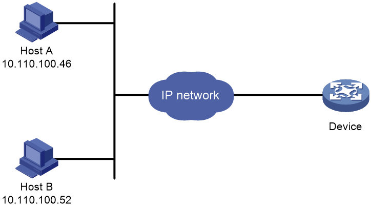
Network configuration
As shown in Figure 13, the device is running SNMP.
Configure the device to allow Host A and Host B to access the device through SNMP.

Procedure
# Create an ACL to permit packets sourced from Host A and Host B.
<Sysname> system-view
[Sysname] acl basic 2000 match-order config
[Sysname-acl-ipv4-basic-2000] rule 1 permit source 10.110.100.52 0
[Sysname-acl-ipv4-basic-2000] rule 2 permit source 10.110.100.46 0
[Sysname-acl-ipv4-basic-2000] quit
# Associate the ACL with the SNMP community and the SNMP group.
[Sysname] snmp-agent community read aaa acl 2000
[Sysname] snmp-agent group v2c groupa acl 2000
[Sysname] snmp-agent usm-user v2c usera groupa acl 2000
Verifying the configuration
# Access the device from the NMS at 10.110.100.52 or 10.110.100.46. You can access the device. (Details not shown.)
# Access the device from any other NMS. You cannot access the device. (Details not shown.)
Configuring command authorization
About command authorization
By default, commands available for a user depend only on the user's user roles. When the authentication mode is scheme, you can configure the command authorization feature to further control access to commands.
After you enable command authorization, a user can use only commands that are permitted by both the AAA scheme and user roles.
Restrictions and guidelines
When command authorization is enabled, commands available for a user vary by the user's login authentication mode.
· If authentication is disabled or password authentication is enabled, command authorization does not take effect, and the user cannot use any commands.
· If scheme authentication is enabled, commands available for a user vary by the user's access authentication method.
¡ If local authentication is used, the device uses the user roles assigned to the user to perform command authorization.
¡ If remote authentication is used, the remote authorization server performs command authorization to determine whether a command entered by a login user is permitted. If remote authorization fails, the device uses the user roles of a local user with the same name as the login user to determine whether the command can be used. If the authorization also fails, the login user cannot use the command.
Command authorization configuration changes in user line class view do not take effect on the current session. The changes take effect only on subsequent login sessions. Command authorization configuration changes in user line view take effect immediately on all users that access the user line.
If the remote server performs command authorization, you must configure a command authorization method in ISP domain view. The command authorization method can be different from the user login authorization method. For more information, see AAA in Security Configuration Guide.
Procedure
1. Enter system view.
system-view
2. Enter user line view or user line class view.
¡ Enter user line view.
line { first-number1 [ last-number1 ] | { aux | console | tty | usb | vty } first-number2 [ last-number2 ] }
¡ Enter user line class view.
line class { aux | console | tty | usb | vty }
A setting in user line view applies only to the user line. A setting in user line class view applies to all user lines of the class. A non-default setting in either view takes precedence over the default setting in the other view. A non-default setting in user line view takes precedence over the non-default setting in user line class view.
A setting in user line class view takes effect only on users who log in after the setting is made. It does not affect users who are already online when the setting is made.
3. Enable scheme authentication.
In non-FIPS mode:
authentication-mode scheme
By default, authentication is disabled for console login, AUX login, and TTY login, and password authentication is enabled for VTY login.
In VTY line view, this command is associated with the protocol inbound command. If one command has a non-default setting in VTY line view, the other command uses its setting in VTY line view, regardless of its setting in VTY line class view.
In FIPS mode:
authentication-mode scheme
By default, scheme authentication is enabled.
In VTY line view, this command is associated with the protocol inbound command. If one command has a non-default setting in VTY line view, the other command uses its setting in VTY line view, regardless of its setting in VTY line class view.
|
|
CAUTION: When you enable scheme authentication, make sure an authentication user account is available. If no authentication user account is available, you cannot log in to the device through the line or line class at the next time. |
4. Enable command authorization.
command authorization
By default, command authorization is disabled, and the commands available for a user only depend on the user role.
If the command authorization command is executed in user line class view, command authorization is enabled on all user lines in the class. You cannot execute the undo command authorization command in the view of a user line in the class.
Example: Configuring command authorization
Network configuration
As shown in Figure 14, Host A needs to log in to the device to manage the device.
Configure the device to perform the following operations:
· Allow Host A to Telnet in after authentication.
· Use the HWTACACS server to control the commands that the user can execute.
· If the HWTACACS server is not available, use local authorization.
Procedure

Procedure
# Assign IP addresses to relevant interfaces. Make sure the device and the HWTACACS server can reach each other. Make sure the device and Host A can reach each other. (Details not shown.)
# Enable the Telnet server.
<Device> system-view
[Device] telnet server enable
# Enable scheme authentication for user lines VTY 0 through VTY 63.
[Device] line vty 0 63
[Device-line-vty0-63] authentication-mode scheme
# Enable command authorization for the user lines.
[Device-line-vty0-63] command authorization
[Device-line-vty0-63] quit
# Create HWTACACS scheme tac.
[Device] hwtacacs scheme tac
# Configure the scheme to use the HWTACACS server at 192.168.2.20:49 for authentication and authorization.
[Device-hwtacacs-tac] primary authentication 192.168.2.20 49
[Device-hwtacacs-tac] primary authorization 192.168.2.20 49
# Set the shared keys to expert.
[Device-hwtacacs-tac] key authentication simple expert
[Device-hwtacacs-tac] key authorization simple expert
# Remove domain names from usernames sent to the HWTACACS server.
[Device-hwtacacs-tac] user-name-format without-domain
[Device-hwtacacs-tac] quit
# Configure the system-defined domain (system).
[Device] domain system
# Use HWTACACS scheme tac for login user authentication and command authorization. Use local authentication and local authorization as the backup method.
[Device-isp-system] authentication login hwtacacs-scheme tac local
[Device-isp-system] authorization command hwtacacs-scheme tac local
[Device-isp-system] quit
# Create local user monitor. Set the simple password to hello12345, the service type to Telnet, and the default user role to level-1.
[Device] local-user monitor
[Device-luser-manage-monitor] password simple hello12345
[Device-luser-manage-monitor] service-type telnet
[Device-luser-manage-monitor] authorization-attribute user-role level-1
Verifying the configuration
# Telnet to the device (10.110.100.77) from Host A. After login, execute the ip http enable command. Because you are not authorized to execute the command, the system displays Permission denied.
C:\> telnet 10.110.100.77
Trying 10.110.100.77 ...
Press CTRL+K to abort
Connected to 10.110.100.77 ...
******************************************************************************
* Copyright (c) 2004-2018 New H3C Technologies Co., Ltd. All rights reserved.*
* Without the owner's prior written consent, *
* no decompiling or reverse-engineering shall be allowed. *
******************************************************************************
login: monitor
Password:
<Device> system-view
System View: return to User View with Ctrl+Z.
[Device] ip http enable
Permission denied.
[Device]
# Execute the interface command. Because you are authorized to execute the command, you enter the interface view.
[Device] interface gigabitethernet 1/0/1
[Device-GigabitEthernet1/0/1]
Configuring command accounting
About command accounting
Command accounting uses the HWTACACS server to record all executed commands to monitor user behavior on the device.
If command accounting is enabled but command authorization is not, every executed command is recorded. If both command accounting and command authorization are enabled, only authorized commands that are executed are recorded.
Restrictions and guidelines
The command accounting method can be the same as or different from the command authorization method and user login authorization method.
For the command accounting feature to take effect, you must configure a command accounting method in ISP domain view. For more information, see Security Configuration Guide.
Procedure
1. Enter system view.
system-view
2. Enter user line view or user line class view.
¡ Enter user line view.
line { first-number1 [ last-number1 ] | { aux | console | tty | usb | vty } first-number2 [ last-number2 ] }
¡ Enter user line class view.
line class { aux | console | tty | usb | vty }
A setting in user line view applies only to the user line. A setting in user line class view applies to all user lines of the class. A non-default setting in either view takes precedence over the default setting in the other view. A non-default setting in user line view takes precedence over the non-default setting in user line class view.
A setting in user line class view takes effect only on users who log in after the setting is made. It does not affect users who are already online when the setting is made.
3. Enable scheme authentication.
In non-FIPS mode:
authentication-mode scheme
By default, authentication is disabled for console login, AUX login, and TTY login, and password authentication is enabled for VTY login.
In VTY line view, this command is associated with the protocol inbound command. If one command has a non-default setting in VTY line view, the other command uses its setting in VTY line view, regardless of its setting in VTY line class view.
In FIPS mode:
authentication-mode scheme
By default, scheme authentication is enabled.
In VTY line view, this command is associated with the protocol inbound command. If one command has a non-default setting in VTY line view, the other command uses its setting in VTY line view, regardless of its setting in VTY line class view.
|
|
CAUTION: When you enable scheme authentication, make sure an authentication user account is available. If no authentication user account is available, you cannot log in to the device through the line or line class at the next time. |
4. Enable command accounting.
command accounting
By default, command accounting is disabled. The accounting server does not record the commands executed by users.
If the command accounting command is executed in user line class view, command accounting is enabled on all user lines in the class. You cannot execute the undo command accounting command in the view of a user line in the class.
Example: Configuring command accounting
Network configuration
As shown in Figure 15, users need to log in to the device to manage the device.
Configure the device to send commands executed by users to the HWTACACS server to monitor and control user operations on the device.
Procedure
# Enable the Telnet server.
<Device> system-view
[Device] telnet server enable
# Enable command accounting for user line console 0.
[Device] line console 0
[Device-line-console0] command accounting
[Device-line-console0] quit
# Enable command accounting for user lines VTY 0 through VTY 63.
[Device] line vty 0 63
[Device-line-vty0-63] command accounting
[Device-line-vty0-63] quit
# Create HWTACACS scheme tac.
[Device] hwtacacs scheme tac
# Configure the scheme to use the HWTACACS server at 192.168.2.20:49 for accounting.
[Device-hwtacacs-tac] primary accounting 192.168.2.20 49
# Set the shared key to expert.
[Device-hwtacacs-tac] key accounting simple expert
# Remove domain names from usernames sent to the HWTACACS server.
[Device-hwtacacs-tac] user-name-format without-domain
[Device-hwtacacs-tac] quit
# Configure the system-defined domain (system) to use the HWTACACS scheme for command accounting.
[Device] domain system
[Device-isp-system] accounting command hwtacacs-scheme tac
[Device-isp-system] quit
Verifying the configuration
# Use Host A, Host B, and Host C as a Telnet or SSH client to log in to the device respectively, and perform VLAN and interface configuration. The accounting server processes accounting packets from the hosts as defined by the accounting settings. (Details not shown.)
