- Table of Contents
-
- 11-Network Management and Monitoring Configuration Guide
- 00-Preface
- 01-System maintenance and debugging configuration
- 02-NQA configuration
- 03-iNQA configuration
- 04-NTP configuration
- 05-PTP configuration
- 06-Network synchronization configuration
- 07-PoE configuration
- 08-SNMP configuration
- 09-RMON configuration
- 10-Event MIB configuration
- 11-NETCONF configuration
- 12-Ansible configuration
- 13-Puppet configuration
- 14-Chef configuration
- 15-SmartMC configuration
- 16-EPA configuration
- 17-ONVIF configuration
- 18-CWMP configuration
- 19-EAA configuration
- 20-Process monitoring and maintenance configuration
- 21-Mirroring configuration
- 22-sFlow configuration
- 23-Information center configuration
- 24-Packet capture configuration
- 25-VCF fabric configuration
- 26-Cloud connection configuration
- 27-EPS agent configuration
- 28-eMDI configuration
- 29-SQA configuration
- Related Documents
-
| Title | Size | Download |
|---|---|---|
| 07-PoE configuration | 191.41 KB |
Contents
Restrictions: Hardware compatibility with PoE
Restrictions and guidelines: PoE configuration
PoE configuration tasks at a glance
Prerequisites for configuring PoE
Disabling PoE on shutdown interfaces
Allowing inrush currents drawn by PDs
Enabling PI power cycling upon a system warm reboot
Enabling nonstandard PD detection
Configuring a PD detection mode
Configuring the maximum PSE power
Configuring the maximum PI power
Configuring the PoE priority policy
Configuring the PI priority policy
Configuring PSE power monitoring
Configuring a PI by using a PoE profile
Upgrading PSE firmware in service
Enabling forced PoE power supply
Display and maintenance commands for PoE
Failure to set the priority of a PI to critical
Failure to apply a PoE profile to a PI
Configuring PoE
About PoE
Power over Ethernet (PoE) enables a network device to supply power to terminals over twisted pair cables.
PoE system
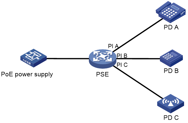
As shown in Figure 1, a PoE system includes the following elements:
· PoE power supply—A PoE power supply provides power for the entire PoE system.
· PSE—A power sourcing equipment (PSE) supplies power to PDs. PSE devices are classified into single-PSE devices and multiple-PSE devices.
¡ A single-PSE device has only one piece of PSE firmware.
¡ A multiple-PSE device has multiple PSEs. A multiple-PSE device uses PSE IDs to identify different PSEs. To view the mapping between the ID and slot number of a PSE, execute the display poe device command.
· PI—A power interface (PI) is a PoE-capable Ethernet interface on a PSE.
· PD—A powered device (PD) receives power from a PSE. PDs include IP telephones, APs, portable chargers, POS terminals, and Web cameras. You can also connect a PD to a redundant power source for reliability.
AI-driven PoE
AI-driven PoE innovatively integrates AI technologies into PoE switches and offers the following benefits:
· Adaptive power supply management
AI-driven PoE can adaptively adjust the power supply parameters to fit power needs in various scenarios such as multiple types of PDs and address issues such as no power supply to a PD and power failure, minimizing human intervention.
· Priority-based power management
When the power demanded by PDs exceeds the power that can be supplied by the PoE switch, the system supplies power to PDs based on the PI priorities to ensure power supply to critical businesses and reduce power supply to PIs of lower priorities.
· Smart power module management
For a PoE switch with a dual power module architecture, AI-driven PoE can automatically calculate and regulate power output of each power module based on the type and quantity of the power modules, maximizing the power usage of each power module. When a power module is removed, AI-driven PoE recalculates to preferentially guarantee power supply to PDs that are being powered.
· Alarms and logs
AI-driven PoE constantly monitors the PoE power supply status. If an exception occurs, it automatically analyzes, recovers, or even resets the PoE function, and outputs alarms and logs for reference.
· High PoE security
When an exception such as short circuit or circuit break occurs, AI-driven PoE immediately starts self-protection to protect the PoE switch from being damaged or burned.
· Fast reboot
Immediately when the PoE switch restarts upon a power failure, AI-driven PoE starts to supply power to PDs before the PoE switch completes startup, shortening the PD recovery time from a power failure.
· Perpetual PoE
During a hot reboot of the PoE switch from the reboot command, AI-driven PoE continuously monitors the PD states and ensures continued power supply to PDs, maintaining terminal service stability.
· Remote PoE
AI-driven PoE adaptively adjusts the network bandwidth based on the transmission distance between a PSE and PD. When the transmission distance exceeds 100 m (328.08 ft), the system automatically decreases the port rate to reduce the line loss and ensure the signal and power transmission quality. With AI-driven PoE enabled, a PSE can transmit power to a PD of 200 to 250 m (656.17 to 820.21 ft) away.
Protocols and standards
· 802.3af-2003, IEEE Standard for Information Technology - Telecommunications and Information Exchange Between Systems - Local and Metropolitan Area Networks - Specific Requirements - Part 3: Carrier Sense Multiple Access with Collision Detection (CSMA/CD) Access Method and Physical Layer Specifications - Data Terminal Equipment (DTE) Power Via Media Dependent Interface (MDI)
· 802.3at-2009, IEEE Standard for Information technology-- Local and metropolitan area networks-- Specific requirements-- Part 3: CSMA/CD Access Method and Physical Layer Specifications Amendment 3: Data Terminal Equipment (DTE) Power via the Media Dependent Interface (MDI) Enhancements
Restrictions: Hardware compatibility with PoE
Only the PoE models support the PoE feature.
Restrictions and guidelines: PoE configuration
You can configure a PI through either of the following ways:
· Configure the settings directly on the PI.
· Configure a PoE profile and apply it to the PI. If you apply a PoE profile to multiple PIs, these PIs have the same PoE features. If you connect a PD to another PI, you can apply the PoE profile of the original PI to the new PI. This method relieves the task of configuring PoE on the new PI.
You can only use one way to configure a parameter for a PI. To use the other way to reconfigure a parameter, you must first remove the original configuration.
You must use the same configuration method for the poe max-power max-power and poe priority { critical | high | low } commands.
PoE configuration tasks at a glance
To configure PoE, perform the following tasks:
1. Enabling PoE
2. (Optional.) Enabling AI-driven PoE
3. (Optional.) Configuring PoE delay
4. (Optional.) Disabling PoE on shutdown interfaces
5. (Optional.) Allowing inrush currents drawn by PDs
6. (Optional.) Enabling PI power cycling upon a system warm reboot
7. (Optional.) Configuring PD detection
¡ Enabling nonstandard PD detection
¡ Configuring a PD detection mode
8. (Optional.) Configuring the PoE power
¡ Configuring the maximum PSE power
¡ Configuring the maximum PI power
9. (Optional.) Configuring the PoE priority policy
¡ Configuring the PI priority policy
10. (Optional.) Configuring PoE monitoring
¡ Configuring PSE power monitoring
11. (Optional.) Configuring a PI by using a PoE profile
To use a PoE profile to enable PoE and configure the priority, power transmission mode, and maximum power for a PI, see "Configuring a PI by using a PoE profile."
12. (Optional.) Upgrading PSE firmware in service
13. (Optional.) Enabling forced PoE power supply
Prerequisites for configuring PoE
Before you configure PoE, make sure the PoE power supply and PSEs are operating correctly.
Enabling PoE
Enabling PoE for a PI
About this task
After you enable PoE for a PI, the PI supplies power to the connected PD if the PI will not result in PSE power overload. PSE overload occurs when the sum of the power consumption of all PIs exceeds the maximum power of the PSE. For more information about the maximum PSE power, see "Configuring the maximum PSE power."
If the PI will result in PSE power overload, the following restrictions apply:
· If the PI priority policy is not enabled, the PI does not supply power to the connected PD.
· If the PI priority policy is enabled, whether the PDs can be powered depends on the priority of the PI.
For more information about the PI priority policy, see "Configuring the PI priority policy."
Power can be transmitted over a twisted pair cable in the following modes:
· Signal pair mode—Signal pairs (on pins 1, 2, 3, and 6) of the twisted pair cable are used for power transmission.
· Spare pair mode—Spare pairs (on pins 4, 5, 7, and 8) of the twisted pair cable are used for power transmission.
Restrictions and guidelines
A PI can supply power to a PD only when the PI and PD use the same power transmission mode.
When you specify a PoE standard for a PI, follow these restrictions and guidelines:
· For your configuration to take effect, restore the PI maximum power to the default before you configure this feature.
· IEEE PoE standards are not forward compatible. For a PI to supply power to PDs, make sure the PoE standard version of the PDs is the same as or earlier than the PoE standard version of the PI.
· If a PI operates in IEEE 802.3bt mode and supplies more than 30 W power, changing the PoE standard for the PI will cause the connected PDs to be power cycled. Be cautious when you modify the configuration of this feature.
Procedure
1. Enter system view.
system-view
2. Enter PI view.
interface interface-type interface-number
3. (Optional.) Configure a description for the PD connected to the PI.
poe pd-description text
By default, no description is configured for the PD connected to the PI.
4. (Optional.) Specify a PoE standard for the PI.
poe standard { at | bt }
By default, a PI complies with the IEEE 802.3bt PoE standard.
5. Enable PoE for the PI.
poe enable
By default, PoE is disabled on a PI.
Enabling AI-driven PoE
Restrictions and guidelines
AI-driven PoE takes effect only on PSEs that run firmware V147 or later.
· PSEs with firmware earlier than V147—You must use the poe update command to upgrade the PSE firmware and then enable AI-driven PoE on it.
· PSEs with firmware V147 or later—You do not need to re-enable AI-driven PoE after upgrading the firmware if you have enabled the feature before the upgrade..
Procedure
1. Enter system view.
system-view
2. Enable AI-driven PoE.
poe ai enable
By default, AI-driven PoE is disabled.
AI-driven PoE automatically adjusts the power supply parameters to fit the power needs. If you disable AI-driven PoE, the system reverts the parameters to the settings before the adjustment.
Configuring PoE delay
About this task
By default, the device executes the poe enable command and supplies power to an interface immediately when any one of the following conditions is met:
· The poe enable command is configured.
· The device reboots with the poe enable command in the configuration file.
· The interface comes up and the PoE module resumes PoE power supply to the interface.
This task creates a PoE delay timer after the poe enable command is executed and allows the PoE module to supply power to the PI only after the timer expires.
Restrictions and guidelines
The undo poe enable command is executed immediately upon configuration and is not affected by this task.
Procedure
1. Enter system view.
system-view
2. Enable PoE delay.
poe power-delay time
By default, PoE delay is disabled.
Disabling PoE on shutdown interfaces
About this task
By default, the device continues supplying power to an interface after the interface is shut down by the shutdown command or by an upper layer module such as monitor link. As a result, the PD connected to the shutdown interface operates continuously but fails to access the network.
This task disables the PoE module from supplying power to an interface after the interface is shut down. After the interface comes up or you disable this task, the PoE module resumes power supply to the interface.
Restrictions and guidelines
The task does not power off an interface that has been shut down but is supplying power to a PD.
Procedure
1. Enter system view.
system-view
2. Disable PoE on shutdown interfaces.
poe track-shutdown
By default, PoE is not disabled on shutdown interfaces.
Allowing inrush currents drawn by PDs
About this task
Inrush current might occur at PD startup and trigger PSE self-protection, As a result, the PSE stops supplying power to the PDs. To continue power supply to the PDs, configure this feature to allow inrush current drawn by PDs.
IEEE 802.3af and IEEE 802.3at define specifications for inrush current.The device supports the specifications for inrush current defined by IEEE 802.3af and IEEE 802.3at.
Restrictions and guidelines
|
|
CAUTION: Inrush current might damage device components. Use this feature with caution. |
Procedure
1. Enter system view.
system-view
2. Allow inrush current drawn by PDs.
poe high-inrush enable pse pse-id
By default, inrush current drawn by PDs is not allowed.
Enabling PI power cycling upon a system warm reboot
About this task
During the system warm reboot process (upon execution of the reboot command), the PIs continue supplying power to the PDs but data connections between the PDs and the device are interrupted. After the system reboots, PDs might not re-initiate data connections with the device. Power cycling PIs upon a system warm reboot allows the PDs to re-establish data connections with the device after a warm reboot.
Procedure
1. Enter system view.
system-view
2. Enter PI power cycling upon a system warm reboot.
poe reset enable
By default, PI power cycling upon a system warm reboot is disabled.
Configuring PD detection
Enabling nonstandard PD detection
About this task
PDs are classified into standard PDs and nonstandard PDs. Standard PDs are compliant with IEEE 802.3af and IEEE 802.3at. A PSE supplies power to a nonstandard PD only after nonstandard PD detection is enabled.
The device supports PSE-based and PI-based nonstandard PD detection. Enabling nonstandard PD detection for a PSE enables this feature for all PIs on the PSE. As a best practice for disabling nonstandard PD detection for all PIs successfully in one operation, disable this feature in both system view and interface view.
Procedure
1. Enter system view.
system-view
2. Enable nonstandard PD detection. Choose one option as needed.
¡ Enable nonstandard PD detection for the PSE.
poe legacy enable pse pse-id
By default, nonstandard PD detection is disabled for a PSE.
¡ Execute the following commands in sequence to enable nonstandard PD detection for a PI:
interface interface-type interface-number
poe legacy enable
By default, nonstandard PD detection is disabled for a PI.
Configuring a PD detection mode
About this task
The device detects PDs in one of the following modes:
· None—The device supplies power to PDs that are correctly connected to the device without causing short circuit.
· Simple—The device supplies power to PDs that comply with basic requirements of 802.3af or 802.3at.
· Strict—The device supplies power to PDs that comply with all requirements of 802.3af or 802.3at.
Restrictions and guidelines
|
|
CAUTION: A non-PD device might be damaged when power is supplied to it. To avoid device damage, do not specify the none mode when the PI connects to a non-PD device. |
For this feature to take effect on nonstandard PDs, you must enable detection for nonstandard PDs by using the poe legacy enable command.
Procedure
1. Enter system view.
system-view
2. Enter PI view.
interface interface-type interface-number
3. Configure the PD detection mode.
poe detection-mode { none | simple | strict }
By default, the PD detection mode is strict.
Configuring the PoE power
Configuring the maximum PSE power
About this task
The maximum power of a PSE is the maximum power that the PSE can provide to all its attached PDs.
Restrictions and guidelines
To avoid the PoE power overload situation, make sure the total power of all PSEs is less than the maximum PoE power.
The maximum power of the PSE must be greater than or equal to the total maximum power of all its PIs of critical priority .
Procedure
1. Enter system view.
system-view
2. Configure the maximum power for a PSE.
poe pse pse-id max-power max-power
The default maximum power of a PSE depends on the installed PoE power supply.
Configuring the maximum PI power
About this task
The maximum PI power is the maximum power that a PI can provide to the connected PD. If the PD requires more power than the maximum PI power, the PI does not supply power to the PD.
Procedure
1. Enter system view.
system-view
2. Enter PI view.
interface interface-type interface-number
3. Configure the maximum power for the PI.
poe max-power max-power
By default, the maximum PI power is 100000 milliwatts.
Configuring the PoE priority policy
Configuring the PI priority policy
About this task
The PI priority policy enables the PSE to perform priority-based power allocation to PIs when PSE power overload occurs. The priority levels for PIs are critical, high, and low in descending order.
When PSE power overload occurs, the PSE supplies power to PDs as follows:
· If the PI priority policy is disabled, the PSE supplies power to PDs depending on whether you have configured the maximum PSE power.
¡ If you have configured the maximum PSE power, the PSE does not supply power to the newly-added or existing PD that causes PSE power overload.
¡ If you have not configured the maximum PSE power, the PoE self-protection mechanism is triggered. The PSE stops supplying power to all PDs.
· If the PI priority policy is enabled, the PSE supplies power to PDs as follows:
¡ If a PD being powered causes PSE power overload, the PSE stops supplying power to the PD.
¡ If a newly-added PD causes PSE power overload, the PSE supplies power to PDs in priority descending order of the PIs to which they are connected. If the newly-added PD and a PD being powered have the same priority, the PD being powered takes precedence. If multiple PIs being powered have the same priority, the PIs with smaller IDs takes precedence.
Restrictions and guidelines
Before you configure a PI with critical priority, make sure the remaining power from the maximum PSE power minus the maximum powers of the existing PIs with critical priority is greater than maximum power of the PI.
Configuration for a PI whose power is preempted remains unchanged.
Procedure
1. Enter system view.
system-view
2. Enable the PI priority policy.
poe pd-policy priority
By default, the PI priority policy is disabled.
3. Enter PI view.
interface interface-type interface-number
4. (Optional.) Configure a priority for the PI.
poe priority { critical | high | low }
By default, the priority for a PI is low.
Configuring PoE monitoring
Configuring PSE power monitoring
About this task
The system monitors PSE power utilization and sends notification messages when PSE power utilization exceeds or drops below the threshold. If PSE power utilization crosses the threshold multiple times in succession, the system sends notification messages only for the first crossing. For more information about the notification message, see "Configuring SNMP."
Procedure
1. Enter system view.
system-view
2. Configure a power alarm threshold for a PSE.
poe utilization-threshold value pse pse-id
By default, the power alarm threshold for a PSE is 80%.
Configuring a PI by using a PoE profile
Restrictions and guidelines
To modify a PoE profile applied on a PI, first remove the PoE profile from the PI.
You can configure a PI either on the PI or by using a PoE profile. The poe max-power max-power and poe priority { critical | high | low } commands must be configured using the same method.
Configuring a PoE profile
1. Enter system view.
system-view
2. Create a PoE profile and enter its view.
poe-profile profile-name [ index ]
By default, no PoE profiles exist.
3. Enable PoE.
poe enable
By default, PoE is disabled.
4. (Optional.) Configure the maximum PI power.
poe max-power max-power
By default, the maximum PI power is 100000 milliwatts.
5. (Optional.) Configure a PI priority.
poe priority { critical | high | low }
The default priority is low.
This command takes effect only after the PI priority policy is enabled.
Applying a PoE profile
Restrictions and guidelines
You can apply a PoE profile to multiple PIs in system view or a single PI in PI view. If you perform the operation in both views for the same PI, the most recent operation takes effect.
You can apply only one PoE profile to a PI.
Applying a PoE profile in system view
1. Enter system view.
system-view
2. Apply a PoE profile to PIs.
apply poe-profile { index index | name profile-name } interface interface-range
By default, a PoE profile is not applied to a PI.
Applying a PoE profile in PI view
1. Enter system view.
system-view
2. Enter PI view.
interface interface-type interface-number
3. Apply the PoE profile to the interface.
apply poe-profile { index index | name profile-name }
By default, a PoE profile is not applied to a PI.
Upgrading PSE firmware in service
About this task
You can upgrade the PSE firmware in service in the following modes:
· Refresh mode—Updates the PSE firmware without deleting it. You can use the refresh mode in most cases.
· Full mode—Deletes the current PSE firmware and reloads a new one. Use the full mode if the PSE firmware is damaged and you cannot execute any PoE commands.
Restrictions and guidelines
If the PSE firmware upgrade fails because of interruption such as a device reboot, you can restart the device and upgrade it in full mode again. After the upgrade, restart the device manually for the new PSE firmware to take effect.
Procedure
1. Enter system view.
system-view
2. Upgrade the PSE firmware in service.
poe update { full | refresh } filename [ pse pse-id ]
Enabling forced PoE power supply
About this task
Before supplying power to a PD, the device performs a detection of the PD. It supplies power to the PD only after the PD passes the detection. If the PD fails the detection but the power provided by the device meets the PD specifications, you can configure this task to enable forced power supply to the PD.
Restrictions and guidelines
This task enables the device to supply power to a PD directly without performing a detection of the PD. To avoid damaging the PD, make sure the power provided by the device meets the PD specifications before configuring this task.
Procedure
1. Enter system view.
system-view
2. Enter PI view.
interface interface-type interface-number
3. Enable forced PoE power supply.
poe force-power
By default, forced PoE power supply is disabled.
|
|
CAUTION: This command enables the device to supply power to a PD directly without performing a detection of the PD. To avoid damaging the PD, make sure the power provided by the device meets the PD specifications before configuring this command. |
Display and maintenance commands for PoE
Execute display commands in any view.
|
Task |
Command |
|
Display general PSE information. |
display poe device [ slot slot-number ] |
|
Display the power supplying information for the specified PI. |
display poe interface [ interface-type interface-number ] |
|
Display power information for PIs. |
display poe interface power [ interface-type interface-number ] |
|
Display detailed PSE information. |
display poe pse [ pse-id ] |
|
Display the power supplying information for all PIs on a PSE. |
display poe pse pse-id interface |
|
Display power information for all PIs on a PSE. |
display poe pse pse-id interface power |
|
Display all information about the PoE profile. |
display poe-profile [ index index | name profile-name ] |
|
Display all information about the PoE profile applied to the specified PI. |
display poe-profile interface interface-type interface-number |
PoE configuration examples
Example: Configuring PoE
Network configuration
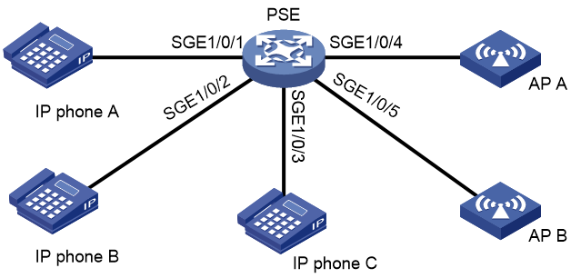
As shown in Figure 2, configure PoE to meet the following requirements:
· The device supplies power to IP phones and APs.
· IP phones take precedence to receive power when power overload occurs.
· Power supplied to AP B does not exceed 9000 milliwatts.
Procedure
# Enable the PI priority policy.
<PSE> system-view
[PSE] poe pd-policy priority
# Enable PoE on Smartrate-Ethernet 1/0/1, Smartrate-Ethernet 1/0/2, and Smartrate-Ethernet 1/0/3, and configure their power supply priority as critical.
[PSE] interface smartrate-ethernet 1/0/1
[PSE-Smartrate-Ethernet1/0/1] poe enable
[PSE-Smartrate-Ethernet1/0/1] poe priority critical
[PSE-Smartrate-Ethernet1/0/1] quit
[PSE] interface smartrate-ethernet 1/0/2
[PSE-Smartrate-Ethernet1/0/2] poe enable
[PSE-Smartrate-Ethernet1/0/2] poe priority critical
[PSE-Smartrate-Ethernet1/0/2] quit
[PSE] interface smartrate-ethernet 1/0/3
[PSE-Smartrate-Ethernet1/0/3] poe enable
[PSE-Smartrate-Ethernet1/0/3] poe priority critical
[PSE-Smartrate-Ethernet1/0/3] quit
# Enable PoE on Smartrate-Ethernet 1/0/4 and Smartrate-Ethernet 1/0/5, and set the maximum power of Smartrate-Ethernet 1/0/5 to 9000 milliwatts.
[PSE] interface smartrate-ethernet 1/0/4
[PSE-Smartrate-Ethernet1/0/4] poe enable
[PSE-Smartrate-Ethernet1/0/4] quit
[PSE] interface smartrate-ethernet 1/0/5
[PSE-Smartrate-Ethernet1/0/5] poe enable
[PSE-Smartrate-Ethernet1/0/5] poe max-power 9000
Verifying the configuration
# Verify that the device is supplying power correctly to the IP phones and APs, and the IP phones and APs are operating correctly.
Troubleshooting PoE
Failure to set the priority of a PI to critical
Symptom
Power supply priority configuration for a PI failed.
Solution
To resolve the issue:
1. Identify whether the remaining guaranteed power of the PSE is lower than the maximum power of the PI. If it is, increase the maximum PSE power or reduce the maximum power of the PI.
2. Identify whether the priority has been configured through other methods. If the priority has been configured, remove the configuration.
3. If the issue persists, contact H3C Support.
Failure to apply a PoE profile to a PI
Symptom
PoE profile application for a PI failed.
Solution
To resolve the issue:
1. Identify whether some settings in the PoE profile have been configured. If they have been configured, remove the configuration.
2. Identify whether the settings in the PoE profile meet the requirements of the PI. If they do not, modify the settings in the PoE profile.
3. Identify whether another PoE profile is already applied to the PI. If it is, remove the application.
4. If the issue persists, contact H3C Support.
