- Table of Contents
-
- 03-Layer 2—LAN Switching Configuration Guide
- 00-Preface
- 01-MAC address table configuration
- 02-Bulk interface configuration
- 03-Ethernet interface configuration
- 04-Ethernet link aggregation configuration
- 05-DRNI configuration
- 06-Port isolation configuration
- 07-VLAN configuration
- 08-MVRP configuration
- 09-Loopback, null, and inloopback interface configuration
- 10-VLAN mapping configuration
- 11-Loop detection configuration
- 12-Spanning tree configuration
- 13-LLDP configuration
- 14-Service loopback group configuration
- 15-Layer 2 forwarding configuration
- Related Documents
-
| Title | Size | Download |
|---|---|---|
| 05-DRNI configuration | 505.09 KB |
Keepalive and failover mechanism
Configuration consistency check
Dual-active gateways on a DR system
DRNI failure handling mechanisms
Mechanisms to handle concurrent IPL and keepalive link failures
Restrictions and guidelines: DRNI configuration
Compatibility with other features
Configuring DR system settings
Configuring the DR system MAC address
Setting the DR system priority
Setting the DR role priority of the device
Enabling DRNI standalone mode on a DR member device
Configuring DR keepalive settings
Restrictions and guidelines for configuring DR keepalive settings
Configuring DR keepalive packet parameters
Setting the DR keepalive interval and timeout timer
Restrictions and guidelines for DRNI MAD
Configuring the default DRNI MAD action on network interfaces
Excluding an interface from the shutdown action by DRNI MAD
Excluding all logical interfaces from the shutdown action by DRNI MAD
Specifying interfaces to be shut down by DRNI MAD when the DR system splits
Enabling DRNI MAD DOWN state persistence
Specifying a Layer 2 aggregate interface or VXLAN tunnel interface as the IPP
Enabling the short DRCP timeout timer on the IPP or a DR interface
Assigning a DRNI virtual IP address to an interface
Setting the mode of configuration consistency check
Disabling configuration consistency check
Setting the keepalive hold timer for identifying the cause of IPL down events
Configuring DR system auto-recovery
Setting the data restoration interval
Enabling DRNI sequence number check
Enabling DRNI packet authentication
Displaying and maintaining DRNI
Example: Configuring basic DRNI functions
Example: Configuring Layer 3 gateways on a DR system
Example: Configure dual-active gateways on a DR system
Configuring DRNI
About DRNI
Distributed Resilient Network Interconnect (DRNI) virtualizes two physical devices into one system through multichassis link aggregation.
DRNI network model
As shown in Figure 1, DRNI virtualizes two devices into a distributed-relay (DR) system, which connects to the remote aggregation system through a multichassis aggregate link. To the remote aggregation system, the DR system is one device.
Figure 1 DRNI network model
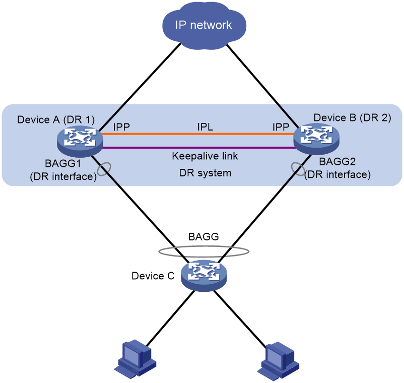
The DR member devices are DR peers to each other. For features that require centralized traffic processing (for example, spanning tree), a DR member device is assigned the primary or secondary role based on its DR role priority. The secondary DR device passes the traffic of those features to the primary DR device for processing. If the DR member devices in a DR system have the same DR role priority, the device with the lower bridge MAC address is assigned the primary role.
DRNI defines the following interface roles for each DR member device:
· DR interface—Layer 2 aggregate interface connected to the remote aggregation system. DR interfaces connected to the same remote aggregation system belong to one DR group. In Figure 1, Bridge-Aggregation 1 on Device A and Bridge-Aggregation 2 on Device B belong to the same DR group. DR interfaces in a DR group form a multichassis aggregate link.
· Intra-portal port (IPP)—Interface connected to the DR peer for internal control. Each DR member device has only one IPP. The IPPs of the DR member devices transmit DRNI protocol packets and data packets through the intra-portal link (IPL) established between them. A DR system has only one IPL.
DR member devices use a keepalive link to monitor each other's state. For more information about the keepalive mechanism, see "Keepalive and failover mechanism."
If a device is attached to only one of the DR member devices in a DR system, that device is a single-homed device.
DRCP
DRNI uses H3C proprietary Distributed Relay Control Protocol (DRCP) for multichassis link aggregation. DRCP runs on the IPL and uses distributed relay control protocol data units (DRCPDUs) to advertise the DRNI configuration out of IPPs and DR interfaces.
DRCP operating mechanism
DRNI-enabled devices use DRCPDUs for the following purposes:
· Exchange DRCPDUs through DR interfaces to determine whether they can form a DR system.
· Exchange DRCPDUs through IPPs to negotiate the IPL state.
DRCP timeout timers
DRCP uses a timeout mechanism to specify the amount of time that an IPP or DR interface must wait to receive DRCPDUs before it determines that the peer interface is down. This timeout mechanism provides the following timer options:
· Short DRCP timeout timer, which is fixed at 3 seconds. If this timer is used, the peer interface sends one DRCPDU every second.
· Long DRCP timeout timer, which is fixed at 90 seconds. If this timer is used, the peer interface sends one DRCPDU every 30 seconds.
Short DRCP timeout timer enables the DR member devices to detect a peer interface down event more quickly than the long DRCP timeout timer. However this benefit is at the expense of bandwidth and system resources.
Keepalive and failover mechanism
H3C provides proprietary keepalive mechanism to detect the availability of the DR member devices.
For the secondary DR device to monitor the state of the primary device, you must establish a Layer 3 keepalive link between the DR member devices.
The DR member devices periodically send keepalive packets over the keepalive link. If a DR member device has not received keepalive packets from the peer when the keepalive timeout timer expires, it determines that the keepalive link is down. When both the keepalive link and the IPL are down, a DR member device acts depending on its role.
· If its role is primary, the device retains its role as long as it has up DR interfaces. If all its DR interfaces are down, its role becomes None.
· If its role is secondary, the device takes over the primary role and retains the role as long as it has up DR interfaces. If all its DR interfaces are down, its role becomes None.
A device with the None role cannot send or receive keepalive packets. Its keepalive link stays in the down state.
If the keepalive link is down while the IPL is up, the DR member devices prompt you to check for keepalive link issues.
If the keepalive link is up while the IPL is down, the DR member devices elect a primary device based on the information in the keepalive packets.
MAD mechanism
DRNI MAD
A multi-active collision occurs if the IPL goes down while the keepalive link is up. To avoid network issues, DRNI MAD shuts down all network interfaces on the secondary DR member device except those manually or automatically excluded.
When the IPL comes up, the secondary DR member device starts a delay timer and begins to restore table entries (including MAC address entries and ARP entries) from the primary DR member device. When the delay timer expires, the secondary DR member device brings up all network interfaces placed in DRNI MAD DOWN state.
DRNI MAD DOWN state persistence
Both of the DR member devices might take the primary role if both of them have DR interfaces in up state after the following series of events occur:
1. The IPL goes down while the keepalive link is up. Then, DRNI MAD shuts down all network interfaces on the secondary DR member device except those excluded from the shutdown action by DRNI MAD.
2. The keepalive link also goes down. Then, the secondary DR member device brings up the network interfaces in DRNI MAD DOWN state and sets its role to primary.
DRNI MAD DOWN state persistence helps avoid the forwarding issues that might occur in the multi-active situation that occurs because the keepalive link goes down while the IPL is down.
Device role calculation
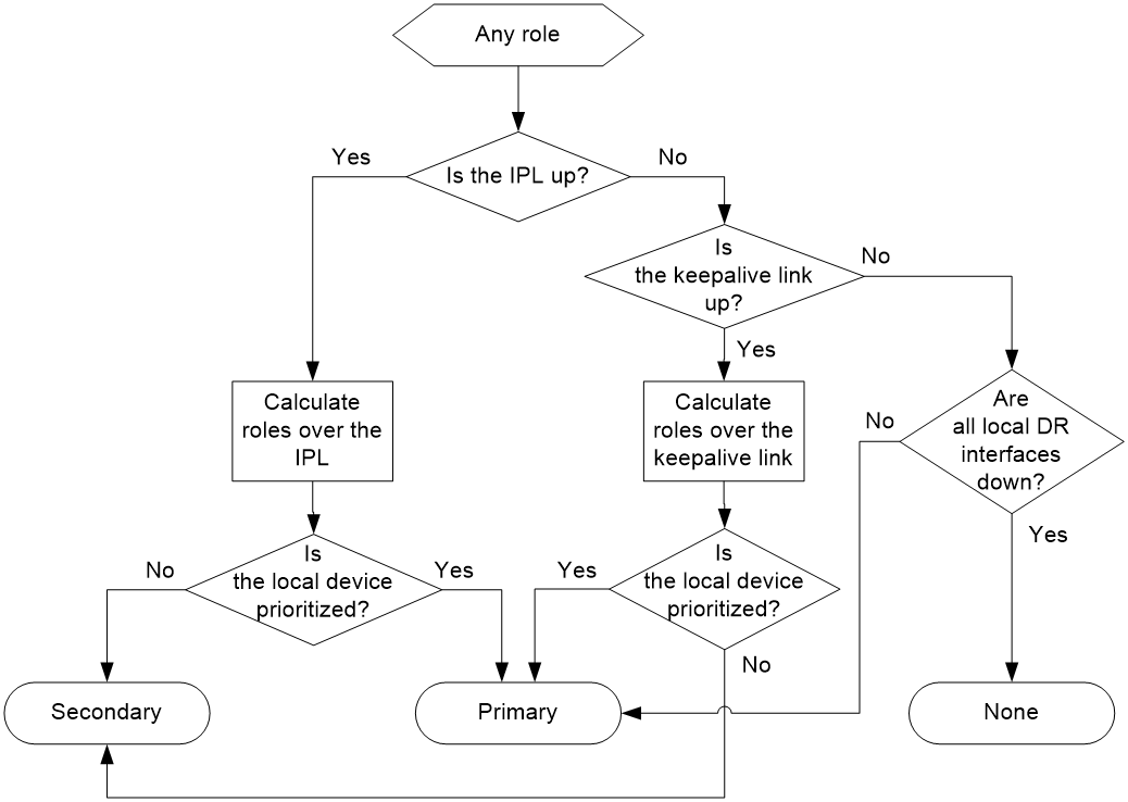
As shown in Figure 2, the role of a DR member device can be primary, secondary, or none after role calculation.
Figure 2 DR role calculation process
Role calculation rules
DRNI calculates the roles of the DR member devices according to the following rules:
· The DR roles are determined upon DR system initialization triggered by DR system setup or reboot of a DR member device.
· If the IPL is up, the DR member devices exchange DRCPDUs over the IPL to determine which of them to take the primary role.
· If the IPL is down while the keepalive link is up, the DR member devices exchange keepalive packets over the link to determine their roles.
· If both the IPL and the keepalive link are down, a DR member device takes the primary role if it has available DR interfaces.
Factors in role calculation
When the IPL or keepalive link is up, the DR member devices exchange the following information to determine which of them takes the primary role:
1. Status of DR interfaces. A DR member device takes the primary role if it has available DR interfaces. This status is skipped if role calculation is performed over the IPL.
2. Device roles before calculation. If one device already has the primary role, the primary device retains its role.
3. DRNI MAD DOWN state. If one device has not placed any network interfaces in DRNI MAD DOWN state, it becomes the primary device.
4. Health state. The healthier device takes the primary role.
To view the health state of the device, execute the display system health command. The smaller the health state value, the healthier the device is. The health state value is 0 if the device is running without faults. For more information about the display system health command, see device management commands in Fundamentals Command Reference.
5. DR role priority. The device with higher DR role priority takes the primary role.
6. Bridge MAC address. The device with a lower bridge MAC address takes the primary role.
The device that has failed the election takes the secondary role.
DR system setup process
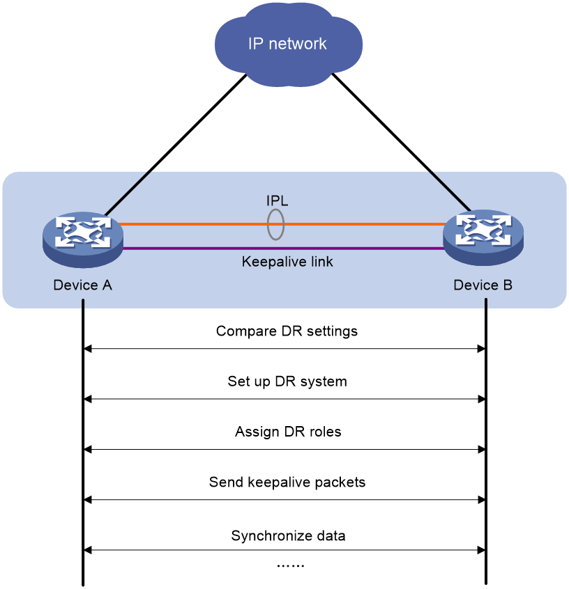
As shown in Figure 3, two devices perform the following operations to form a DR system:
1. Send DRCPDUs over the IPL to each other and compare the DRCPDUs to determine the DR system stackability and device roles:
a. Compare the DR system settings. The devices can form a DR system if they have consistent DR system settings.
b. Determine the device roles as described in "Device role calculation."
c. Perform configuration consistency check. For more information, see "Configuration consistency check."
2. Send keepalive packets over the keepalive link after primary DR member election to verify that the peer system is operating correctly.
3. Synchronize configuration data by sending DRCPDUs over the IPL. The configuration data includes MAC address entries and ARP entries.
Figure 3 DR system setup process
DRNI standalone mode
The DR member devices might both operate with the primary role to forward traffic if they have DR interfaces in up state after the DR system splits. DRNI standalone mode helps avoid traffic forwarding issues in this multi-active situation by allowing only the member ports in the DR interfaces on one member device to forward traffic.
The following information describes the operating mechanism of this feature.
The DR member devices change to DRNI standalone mode when they detect that both the IPL and the keepalive link are down. In addition, the secondary DR member device changes its role to primary.
In DRNI standalone mode, the LACPDUs sent out of a DR interface by each DR member device contain the interface-specific LACP system MAC address and LACP system priority.
The Selected state of the member ports in the DR interfaces in a DR group depends on their LACP system MAC address and LACP system priority. If a DR interface has a lower LACP system priority value or LACP system MAC address, the member ports in that DR interface become Selected to forward traffic. If those Selected ports fail, the member ports in the DR interface on the other DR member device become Selected to forward traffic.
|
|
NOTE: A DR member device changes to DRNI standalone mode only when it detects that both the IPL and the keepalive link are down. It does not change to DRNI standalone mode when the peer DR member device reboots. |
Configuration consistency check
During DR system setup, DR member devices exchange the configuration and perform configuration consistency check to verify their consistency in the following configurations:
· Type 1 configuration—Settings that affect traffic forwarding of the DR system. If an inconsistency in type 1 configuration is detected, the secondary DR device shuts down its DR interfaces.
· Type 2 configuration—Settings that affect only service features. If an inconsistency in type 2 configuration is detected, the secondary DR device disables the affected service features, but it does not shut down its DR interfaces.
To prevent interface flapping, the DR system performs configuration consistency check when half the data restoration internal elapses.
|
|
NOTE: The data restoration interval specifies the maximum amount of time for the secondary DR device to synchronize data with the primary DR device during DR system setup. For more information, see "Setting the data restoration interval." |
Type 1 configuration
Type 1 configuration consistency check is performed both globally and on DR interfaces. Table 1 and Table 2 show settings that type 1 configuration contains.
Table 1 Global type 1 configuration
|
Setting |
Details |
|
IPP link type |
IPP link type, including access, hybrid, and trunk. |
|
PVID on the IPP |
PVID on the IPP. |
|
Spanning tree state |
· Global spanning tree state. · VLAN-specific spanning tree state. DRNI checks the VLAN-specific spanning tree state only when PVST is enabled. |
|
Spanning tree mode |
Spanning tree mode, including STP, RSTP, PVST, and MSTP. |
|
MST region settings |
· MST region name. · MST region revision level. · VLAN-to-MSTI mappings. |
Table 2 DR interface type 1 configuration
|
Setting |
Details |
|
Aggregation mode |
Aggregation mode, including static and dynamic. |
|
Spanning tree state |
Interface-specific spanning tree state. |
|
Link type |
Interface link type, including access, hybrid, and trunk. |
|
PVID |
Interface PVID. |
Type 2 configuration
Type 2 configuration consistency check is performed both globally and on DR interfaces. Table 3 and Table 4 show settings that type 2 configuration contains.
Table 3 Global type 2 configuration
|
Setting |
Details |
|
VLAN interfaces |
Up VLAN interfaces of which the VLANs contain the IPP. |
|
Passing tagged VLANs or passing PVID |
VLANs of which the IPP forwards tagged traffic or PVID of which the IPP forwards traffic. |
Table 4 DR interface type 2 configuration
|
Setting |
Details |
|
Passing tagged VLANs |
VLANs of which a DR interface forwards tagged traffic. |
|
Passing untagged VLANs |
VLANs of which a DR interface forwards untagged traffic. |
Dual-active gateways on a DR system
When a Layer 3 network is dualhomed to a DR system, each DR member device uses a logical interface as the gateway interface for the Layer 3 network. Both logical interfaces are active to perform Layer 3 forwarding, and they use the same IP address and MAC address. When both links to the DR system are operating correctly, the links load share traffic to balance bandwidth usage. When one of the links fails, the DR system switches the traffic on the failed link to the other link to ensure high availability.
DRNI sequence number check
DRNI sequence number check protects DR member devices from replay attacks.
With this feature enabled, the DR member devices insert a sequence number into each outgoing DRCPDU or keepalive packet and the sequence number increases by 1 for each sent packet. When receiving a DRCPDU or keepalive packet, the DR member devices check its sequence number and drop the packet if the check result is either of the following:
· The sequence number of the packet is the same as that of a previously received packet.
· The sequence number of the packet is smaller than that of the most recently received packet.
DRNI packet authentication
DRNI packet authentication prevents DRCPDU and keepalive packet tampering from causing link flapping.
With this feature enabled, the DR member devices compute a message digest by using an authentication key for each outgoing DRCPDU or keepalive packet and insert the message digest into the packet. When receiving a DRCPDU or keepalive packet, a DR member device computes a message digest and compares it with the message digest in the packet. If the message digests match, the packet passes authentication. If the message digests do not match, the device drops the packet.
DRNI failure handling mechanisms
DR interface failure handling mechanism
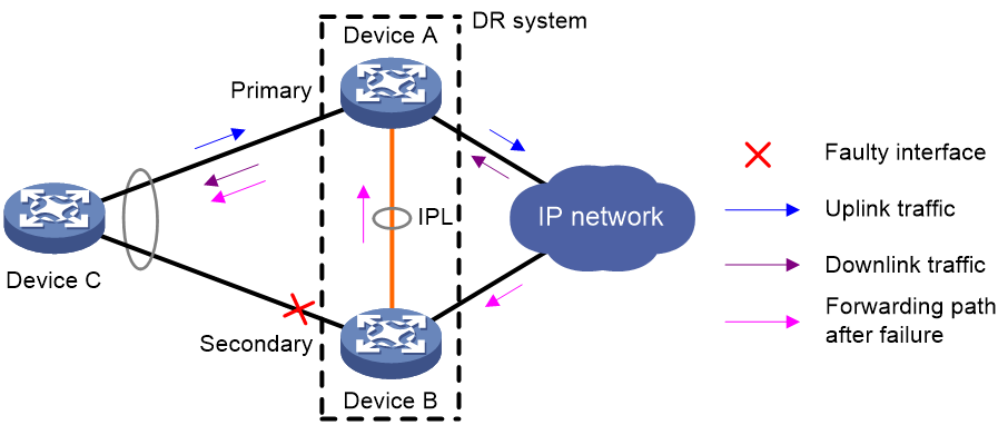
As shown in Figure 4, Device A and Device B form a DR system, to which Device C is attached through a multichassis aggregation. If traffic to Device C arrives at Device B after the DR interface connected Device B to Device C has failed, the DR system forwards the traffic as follows:
1. Device B sends the traffic to Device A over the IPL.
2. Device A forwards the downlink traffic received from the IPL to Device C.
After the faulty DR interface comes up, Device B forwards traffic to Device C through the DR interface.
Figure 4 DR interface failure handling mechanism
IPL failure handling mechanism
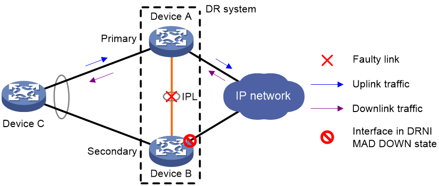
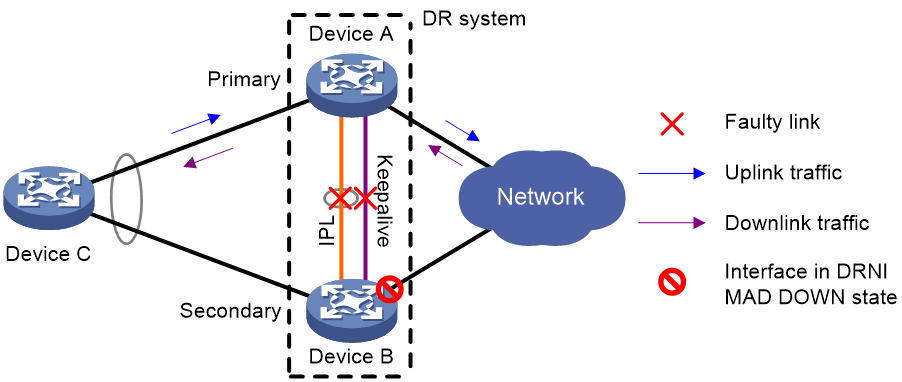
As shown in Figure 5, multi-active collision occurs if the IPL goes down while the keepalive link is up. To avoid network issues, the secondary DR device sets all network interfaces to DRNI MAD DOWN state, except for the interfaces excluded from the shutdown action by DRNI MAD.
In this situation, the primary DR device forwards all traffic for the DR system.
When the IPP comes up, the secondary DR device does not bring up the network interfaces immediately. Instead, it starts a delay timer and begins to recover data from the primary DR device. When the delay timer expires, the secondary DR device brings up all network interfaces.
Figure 5 IPL failure handling mechanism
Device failure handling mechanism
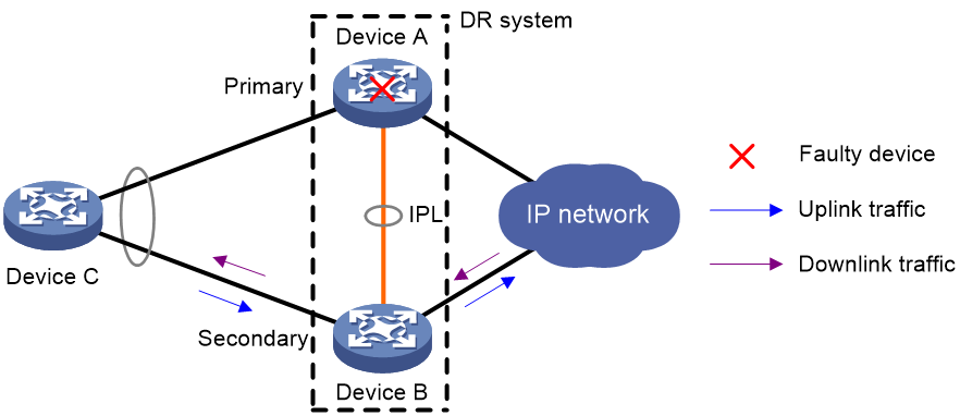
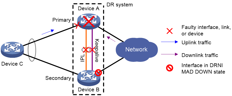
As shown in Figure 6, when the primary DR device fails, the secondary DR device takes over the primary role to forward all traffic for the DR system. When the faulty device recovers, it becomes the secondary DR device.
When the secondary DR device fails, the primary DR device forwards all traffic for the DR system.
Figure 6 Device failure handling mechanism
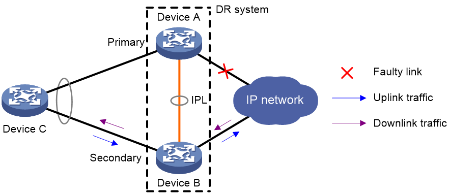
Uplink failure handling mechanism
Uplink failure does not interrupt traffic forwarding of the DR system. As shown in Figure 7, when the uplink of Device A fails, Device A passes traffic destined for the IP network to Device B for forwarding.
To enable faster traffic switchover in response to an uplink failure and minimize traffic losses, configure Monitor Link to associate the DR interfaces with the uplink interfaces. When the uplink interface of a DR member device fails, that device shuts down its DR interface for the other DR member device to forward all traffic of Device C. For more information about Monitor Link, see High Availability Configuration Guide.
Figure 7 Uplink failure handling mechanism
Mechanisms to handle concurrent IPL and keepalive link failures
When both the IPL and the keepalive link are down, the DR member devices handle this situation depending on your configuration.
Default failure handling mechanism
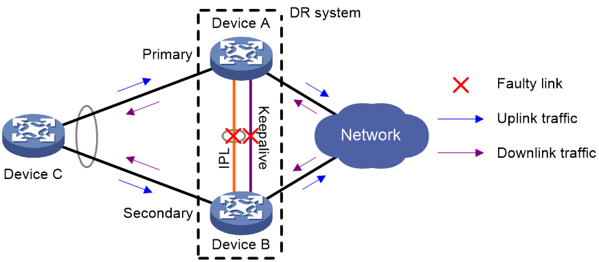
Figure 8 shows the default mechanism to handle IPL and keepalive link failures when the DRNI standalone mode and DRNI MAD DOWN state persistency features are not configured.
· If the IPL goes down while the keepalive link is up, the DR member devices negotiate their roles over the keepalive link. DRNI MAD shuts down all network interfaces on the secondary DR member device except those excluded from the shutdown action by DRNI MAD.
· If the keepalive link goes down while the IPL is down, the secondary DR member device sets its role to primary and brings up the network interfaces in DRNI MAD DOWN state to forward traffic. In this situation, both of the DR member devices might operate with the primary role to forward traffic. Forwarding errors might occur because the DR member devices cannot synchronize MAC address entries over the IPL.
· If the keepalive link is down before the IPL goes down, DRNI MAD will not place network interfaces in DRNI MAD DOWN state. Both DR member devices can operate with the primary role to forward traffic.
Figure 8 Default failure handling mechanism
Failure handling mechanism with DRNI MAD DOWN state persistence
Figure 9 shows the mechanism to handle IPL and keepalive link failures when the DRNI MAD DOWN state persistence feature is configured.
· If the IPL goes down while the keepalive link is up, the DR member devices negotiate their roles over the keepalive link. DRNI MAD shuts down all network interfaces on the secondary DR member device except those excluded from the shutdown action by DRNI MAD.
· If the keepalive link goes down while the IPL is down, the secondary DR member device sets its role to primary, but it does not bring up the network interfaces in DRNI MAD DOWN state. Only the original primary member device can forward traffic.
· If the keepalive link is down before the IPL goes down, DRNI MAD will not place network interfaces in DRNI MAD DOWN state. Both DR member devices can operate with the primary role to forward traffic.
Figure 9 Failure handling mechanism with DRNI MAD DOWN state persistence
As shown in Figure 10, you can bring up the interfaces in DRNI MAD DOWN state on the secondary DR member device for it to forward traffic if the following conditions exist:
· Both the IPL and the keepalive link are down.
· The primary DR member device fails or its DR interface fails.
Figure 10 Bringing up the interfaces in DRNI MAD DOWN state
Failure handling mechanism with DRNI standalone mode
Figure 11 shows the mechanism to handle IPL and keepalive link failures when the DRNI standalone mode feature is configured.
· If the IPL goes down while the keepalive link is up, the DR member devices negotiate their roles over the keepalive link. DRNI MAD shuts down all network interfaces on the secondary DR member device except those excluded from the shutdown action by DRNI MAD.
· If the keepalive link goes down while the IPL is down, both DR member devices change to DRNI standalone mode. The secondary DR member device sets its role to primary and brings up its network interfaces in DRNI MAD DOWN state. In DRNI standalone mode, only the aggregation member ports on one DR member device can become Selected to forward traffic. For more information about how DRNI standalone mode operates, see "DRNI standalone mode."
· If the keepalive link is down before the IPL goes down, both DR member devices change to DRNI standalone mode.
Figure 11 Failure handling mechanism with DRNI standalone mode

Protocols and standards
IEEE P802.1AX-REV™/D4.4c, Draft Standard for Local and Metropolitan Area Networks
Restrictions and guidelines: DRNI configuration
DRNI configuration
DR system configuration
DRNI is an H3C proprietary protocol. You cannot use DR interfaces for communicating with third-party devices.
You can assign two member devices to a DR system. For the DR member devices to be identified as one DR system by the upstream or downstream devices, you must configure the same DR system MAC address and DR system priority on the DR member devices. You must assign different DR system numbers to the DR member devices.
Make sure each DR system uses a unique DR system MAC address.
To ensure correct forwarding, delete DRNI configuration from a DR member device if it leaves its DR system.
IPL
In addition to protocol packets, the IPL also transmits data packets between the DR member devices when an uplink fails.
If a DR member device is a modular device, assign at least one port on each slot to the aggregation group for the IPP as a best practice. This configuration prevents asynchronous service module reboots from causing IPL flapping after a device reboot. As a best practice, make sure at least one member port resides on a different slot than the uplink interfaces.
Make sure the member ports in the aggregation group of the IPP have the same speed.
If a leaf-tier DR system is attached to a large number of servers whose NICs operate in active/standby mode, take the size of the traffic sent among those servers into account when you determine the bandwidth of the IPL.
As a best practice to reduce the impact of interface flapping on upper-layer services, use the link-delay command to configure the same link delay settings on the IPPs. Do not set the link delay to 0.
In a DR system , two IPPs must have the same configuration for the maximum jumbo frame length.
For the DR system to correctly forward traffic for single-homed devices, set the link type to trunk for the IPPs and the interfaces attached to the single-homed devices. If you fail to do so, the ND protocol packets sent to or from the single-homed devices cannot be forwarded over the IPL.
Keepalive link
The DR member devices exchange keepalive packets over the keepalive link to detect multi-active collisions when the IPL is down.
As a best practice, establish a dedicated direct link between two DR member devices as a keepalive link. Do not use the keepalive link for any other purposes. Make sure the DR member devices have Layer 2 and Layer 3 connectivity to each other over the keepalive link.
You can use management Ethernet interfaces, Layer 3 Ethernet interfaces, Layer 3 aggregate interfaces, or interfaces with a bound VPN instance to set up the keepalive link. As a best practice, do not use VLAN interfaces for keepalive link setup. If you have to use VLAN interfaces, remove the IPPs from the related VLANs to avoid loops.
On a modular device, do not use the same module to provide interfaces for setting up the keepalive link and IPL.
For correct keepalive detection, you must exclude the physical and logical interfaces used for keepalive detection from the shutdown action by DRNI MAD.
DR interface
DR interfaces in the same DR group must use the different LACP system MAC addresses.
As a best practice, use the undo lacp period command to enable the long LACP timeout timer (90 seconds) on a DR system.
You must execute the lacp edge-port command on the DR interfaces attached to bare metal servers.
Compatibility with other features
GIR
Before you change a DR system back to normal mode by using the undo gir system-mode maintenance command, execute the display drni mad verbose command to verify that no network interfaces are in DRNI MAD DOWN state. For information about GIR, see Fundamentals Configuration Guide.
IRF
DRNI cannot work correctly on an IRF fabric. Do not configure DRNI on an IRF fabric. To use DRNI on a device, first configure it to operate in standalone mode. For more information about IRF, see Virtual Technologies Configuration Guide.
MAC address table
If the DR system has a large number of MAC address entries, set the MAC aging timer to a higher value than 20 minutes as a best practice. To set the MAC aging timer, use the mac-address timer command.
Use the default setting for the MAC address learning feature on the IPP. Do not execute the mac-address mac-learning enable or undo mac-address mac-learning enable command on the IPP.
Before you assign MAC addresses, configure the base MAC address by using the routing-interface base-mac command.
Table 5 MAC address assignment
|
Device |
Bridge MAC address |
Base MAC address |
DR system MAC address |
EVPN global MAC address |
MAC address of the VSI interface assigned an L3VNI |
MAC address of a gateway VLAN interface |
MAC address of a VSI interface |
|
DR member device 1 |
7057-bff9-aa00 |
Lower bridge MAC address + 64: 542b-de0c-0264 |
Lower base MAC address: 542b-de0c-0200 |
Lower base MAC address + 1: 542b-de0c-0201 |
EVPN global MAC address: 542b-de0c-0201 |
Default: base MAC address + 1, which is 542b-de0c-0265 Recommended: Lower base MAC address + c8, which is 542b-de0c-02c8 |
Default: base MAC address + 1, which is 542b-de0c-0265 Recommended: EVPN global MAC address, which is 542b-de0c-0201 |
|
DR member device 2 |
542b-de0c-0200 |
Lower bridge MAC address: 542b-de0c-0200 |
Lower base MAC address: 542b-de0c-0200 |
Lower base MAC address + 1: 542b-de0c-0201 |
EVPN global MAC address: 542b-de0c-0201 |
Default: base MAC address + 1, which is 542b-de0c-0201 Recommended: Lower base MAC address + c8, which is 542b-de0c-02c8 |
Default: base MAC address + 1, which is 542b-de0c-0201 Recommended: EVPN global MAC address, which is 542b-de0c-0201 |
To view the bridge MAC address, execute the debugging system bridgemac read command in probe view and examine the BridgeMac field.
[Sysname-probe]debugging system bridgemac read
The Bridge Macs are as follows:
542b-de0c-0200
Total reserved mac number: 256
SNID:23a6-db6c-d829-a93d
BridgeMac:542b-de0c-0200 BaseInfMac:542b-de0c-0200 INTFMac:542b-de0c-0201
Make sure the higher 36 bits in the MAC addresses assigned to VSI interfaces are the same as those in the base MAC address. As a best practice, configure VSI interfaces to use the EVPN global MAC address.
For more information about the base MAC address, see "Configuring the MAC address table."
Ethernet link aggregation
Do not configure automatic link aggregation on a DR system.
The aggregate interfaces in an S-MLAG group cannot be used as DR interfaces or IPPs.
When you configure a DR interface, follow these restrictions and guidelines:
· As a best practice, use the undo lacp period command to enable the long LACP timeout timer (90 seconds) on a DR system.
· The link-aggregation selected-port maximum and link-aggregation selected-port minimum commands do not take effect on a DR interface.
· If you execute the display link-aggregation verbose command for a DR interface, the displayed system ID contains the DR system MAC address and the DR system priority.
· If the reference port is a member port of a DR interface, the display link-aggregation verbose command displays the reference port on both DR member devices.
For more information about Ethernet link aggregation, see "Configuring Ethernet link aggregation."
Port isolation
Do not assign DR interfaces and IPP to the same port isolation group. For more information about port isolation, see "Configuring port isolation."
Spanning tree
When the spanning tree protocol is enabled for a DR system, follow these restrictions and guidelines:
· Make sure the DR member devices have the same spanning tree configuration. Violation of this rule might cause network flapping. The configuration includes:
¡ Global spanning tree configuration.
¡ Spanning tree configuration on the IPP.
¡ Spanning tree configuration on DR interfaces.
· IPPs of the DR system do not participate in spanning tree calculation.
· The DR member devices still use the DR system MAC address after the DR system splits, which will cause spanning tree calculation issues. To avoid the issues, enable DRNI standalone mode on the DR member devices before the DR system splits.
For more information about spanning tree, see "Configuring spanning tree."
CFD
Do not use the MAC address of a remote MEP for CFD tests on IPPs. These tests cannot work on IPPs. For more information about CFD, see High Availability Configuration Guide.
VRRP
If you use DRNI and VRRP together, make sure the keepalive hold timer is shorter than the interval at which the VRRP master sends VRRP advertisements. Violation of this restriction might cause a VRRP master/backup switchover to occur before IPL failure is confirmed. To set the interval at which the VRRP master sends VRRP advertisements, use the vrrp vrid timer advertise or vrrp ipv6 vrid timer advertise command. For more information about the commands, see High Availability Command Reference.
Mirroring
For a mirroring group, do not assign the source port to an aggregation group other than the one that accommodates the destination port, egress port, or reflector port. If the source port is in a different aggregation group than the other ports, mirrored LACPDUs will be transmitted between the aggregation groups and cause aggregate interface flapping.
VXLAN and EVPN
For information about VXLAN and EVPN restrictions, see VXLAN Configuration Guide and EVPN VXLAN configuration in EVPN Configuration Guide.
EVPN-DCI
If you use DRNI and EVPN-DCI together, the EDs in a DR system send remote EDs the BGP EVPN routes that carry the virtual IP address of the DR system in the next hop field. Because a directly connected EBGP peer performs recursion only for the EBGP routes in which the next hop is a directly connected subnet, the remote EDs cannot perform recursion for the received BGP EVPN routes. As a result, VXLAN-DCI tunnel setup fails. To resolve this issue, execute the peer ebgp-max-hop command on all EDs when you configure EBGP sessions. For more information about this command, see BGP commands in Layer 3—IP Routing Command Reference.
DRNI tasks at a glance
To configure DRNI, perform the following tasks:
1. Configuring DR system settings
¡ Configuring the DR system MAC address
¡ Setting the DR system number
¡ Setting the DR system priority
2. Setting the DR role priority of the device
3. (Optional.) Enabling DRNI standalone mode on a DR member device
4. Configuring DR keepalive settings
¡ Configuring DR keepalive packet parameters
¡ Setting the DR keepalive interval and timeout timer
¡ Configuring the default DRNI MAD action on network interfaces
¡ Excluding an interface from the shutdown action by DRNI MAD
¡ Excluding all logical interfaces from the shutdown action by DRNI MAD
¡ Specifying interfaces to be shut down by DRNI MAD when the DR system splits
¡ Enabling DRNI MAD DOWN state persistence
6. Configuring interfaces on the DR system
¡ Specifying a Layer 2 aggregate interface or VXLAN tunnel interface as the IPP
¡ (Optional.) Enabling the short DRCP timeout timer on the IPP or a DR interface
7. (Optional.) Assigning a DRNI virtual IP address to an interface
8. (Optional.) Configuring configuration consistency check
¡ Setting the mode of configuration consistency check
¡ Disabling configuration consistency check
Configuration consistency check might fail when you upgrade the DR member devices in a DR system. To prevent the DR system from falsely shutting down DR interfaces, you can temporarily disable configuration consistency check.
9. Configuring DRNI timers
¡ (Optional.) Setting the keepalive hold timer for identifying the cause of IPL down events
¡ Configuring DR system auto-recovery
¡ (Optional.) Setting the data restoration interval
10. (Optional.) Configuring DRNI security features
¡ Enabling DRNI sequence number check
¡ Enabling DRNI packet authentication
Configuring DR system settings
Configuring the DR system MAC address
Restrictions and guidelines
On a DR system, DR interfaces in the same DR group must use the same LACP system MAC address. As a best practice, use the bridge MAC address of one DR member device as the DR system MAC address.
Changing the DR system MAC address causes DR system split. When you perform this task on a live network, make sure you are fully aware of its impact.
You can configure the DR system MAC address on an aggregate interface only after it is configured as a DR interface.
You can configure the DR system MAC address globally and in aggregate interface view. The global DR system MAC address takes effect on all aggregation groups. On an aggregate interface, the interface-specific DR system MAC address takes precedence over the global DR system MAC address.
Procedure
1. Enter system view.
system-view
2. Configure the DR system MAC address.
drni system-mac mac-address
By default, the DR system MAC address is not configured.
3. Enter Layer 2 aggregate interface view.
interface bridge-aggregation interface-number
4. Set the DR system MAC address on the aggregate interface.
port drni system-mac mac-address
By default, the DR system MAC address is not configured.
Setting the DR system number
Restrictions and guidelines
Changing the DR system number causes DR system split. When you perform this task on a live network, make sure you are fully aware of its impact.
You must assign different DR system numbers to the DR member devices in a DR system.
Procedure
1. Enter system view.
system-view
2. Set the DR system number.
drni system-number system-number
By default, the DR system number is not set.
Setting the DR system priority
About this task
A DR system uses its DR system priority as the system LACP priority to communicate with the remote aggregation system.
Restrictions and guidelines
Changing the DR system priority in system view causes DR system split. When you perform this task on a live network, make sure you are fully aware of its impact.
You must configure the same DR system priority for the DR interfaces in the same DR group.
You can configure the DR system priority on an aggregate interface only after it is configured as a DR interface.
You can configure the DR system priority globally and in aggregate interface view. The global DR system priority takes effect on all aggregation groups. On an aggregate interface, the interface-specific DR system priority takes precedence over the global DR system priority.
Procedure
1. Enter system view.
system-view
2. Set the DR system priority.
drni system-priority system-priority
By default, the DR system priority is 32768.
3. Enter Layer 2 aggregate interface view.
interface bridge-aggregation interface-number
4. Set the DR system priority on the aggregate interface.
port drni system-priority priority
By default, the DR system priority is 32768.
Setting the DR role priority of the device
About this task
DRNI assigns the primary or secondary role to a DR member device based on its DR role priority. The smaller the priority value, the higher the priority. If the DR member devices in a DR system use the same DR role priority, the device with the lower bridge MAC address is assigned the primary role.
Restrictions and guidelines
To prevent a primary/secondary role switchover from causing network flapping, avoid changing the DR priority assignment after the DR system is established.
Procedure
1. Enter system view.
system-view
2. Set the DR role priority of the device.
drni role priority priority-value
By default, the DR role priority of the device is 32768.
Enabling DRNI standalone mode on a DR member device
About this task
Perform this task to avoid forwarding issues in the multi-active situation that might occur after both the IPL and the keepalive link are down.
DRNI standalone mode helps avoid traffic forwarding issues in this multi-active situation by allowing only the member ports in the DR interfaces on one member device to forward traffic. For more information about this mode, see "DRNI standalone mode."
When you configure this feature, you can configure a delay to prevent an unnecessary mode change because of transient link down issues.
Restrictions and guidelines
A DR member device changes to DRNI standalone mode only when it detects that both the IPL and the keepalive link are down. It does not change to DRNI standalone mode when the peer DR member device reboots, because the peer notifies the DR member device of the reboot event.
As a best practice, enable DRNI standalone mode on both DR member devices.
Before you enable DRNI standalone mode on a DR member device, make sure its LACP system priority is higher than that of the remote aggregation system. This restriction ensures that the reference port is on the remote aggregation system and prevents the interfaces attached to the DR system from flapping.
Procedure
1. Enter system view.
system-view
2. Enable DRNI standalone mode.
drni standalone enable [ delay delay-time ]
By default, DRNI standalone mode is disabled.
Configuring DR keepalive settings
Restrictions and guidelines for configuring DR keepalive settings
As a best practice, establish a dedicated direct link between DR member devices as a keepalive link. Do not use the keepalive link for any other purposes. Make sure the DR member devices have Layer 2 and Layer 3 connectivity to each other over the keepalive link.
Configuring DR keepalive packet parameters
About this task
Perform this task to specify the parameters for sending DR keepalive packets, such as its source and destination IP addresses.
The device accepts only keepalive packets that are sourced from the specified destination IP address. The keepalive link goes down if the device receives keepalive packets sourced from any other IP address.
Restrictions and guidelines
Make sure the DR member devices in a DR system use the same keepalive destination UDP port.
Procedure
1. Enter system view.
system-view
2. Configure DR keepalive packet parameters.
drni keepalive { ip | ipv6 } destination { ipv4-address | ipv6-address } [ source { ipv4-address | ipv6-address } | udp-port udp-number | vpn-instance vpn-instance-name ] *
By default, the DR keepalive packet parameters are not configured. If you do not specify a source IP address or destination UDP port when you execute this command, the IP address of the outgoing interface and UDP port 6400 are used, respectively.
Setting the DR keepalive interval and timeout timer
About this task
The device sends keepalive packets at the specified interval to its DR peer. If the device has not received a keepalive packet from the DR peer before the keepalive timeout timer expires, the device determines that the keepalive link is down.
Restrictions and guidelines
The local DR keepalive timeout timer must be two times the DR keepalive interval of the peer at minimum.
Configure the same DR keepalive interval on the DR member devices in the DR system.
Procedure
1. Enter system view.
system-view
2. Set the DR keepalive interval and timeout timer.
drni keepalive interval interval [ timeout timeout ]
By default, the DR keepalive interval is 1000 milliseconds, and the DR keepalive timeout timer is 5 seconds.
Configuring DRNI MAD
About this task
DRNI MAD configuration methods
When you configure DRNI MAD, use either of the following methods:
· To shut down all network interfaces on the secondary DR member device except a few special-purpose interfaces that must be retained in up state:
¡ Set the default DRNI MAD action to DRNI MAD DOWN. For more information, see "Configuring the default DRNI MAD action on network interfaces."
¡ Exclude interfaces from being shut down by DRNI MAD. For more information, see "Excluding an interface from the shutdown action by DRNI MAD."
This method is applicable to most network environments.
· To have the secondary DR member device retain a large number of interfaces in up state and shut down the remaining interfaces:
¡ Set the default DRNI MAD action to NONE. For more information, see "Configuring the default DRNI MAD action on network interfaces."
¡ Specify network interfaces that must be shut down by DRNI MAD. For more information, see "Specifying interfaces to be shut down by DRNI MAD when the DR system splits."
One applicable scenario of this method is the EVPN environment in which you use a VXLAN tunnel as the IPL. In this scenario, you must retain a large number of logical interfaces (for example, VLAN, aggregate, loopback, tunnel, and VSI interfaces) in up state.
List of automatically included interfaces
DRNI MAD will always shut down the ports in the system-configured included port list if the device acts as the secondary DR member device when the DR system splits.
This list contains aggregation member ports of DR interfaces. To identify system-configured included ports, execute the display drni mad verbose command.
List of automatically excluded interfaces
DRNI MAD will not shut down the ports in the following list when the DR system splits:
· System-configured excluded port list in DRNI MAD:
¡ IPP.
¡ Aggregation member interfaces if a Layer 2 aggregate interface is used as the IPP.
¡ DR interfaces.
¡ Management interfaces.
To identify these interfaces, execute the display drni mad verbose command.
· Interfaces manually or automatically excluded from being shut down by IRF MAD. To identify these interfaces, execute the display mad verbose command.
· Network interfaces used for special purposes, including:
¡ Interfaces placed in a loopback test by using the loopback command.
¡ Interfaces assigned to a service loopback group by using the port service-loopback group command.
¡ Mirroring reflector ports configured by using the mirroring-group reflector-port command.
¡ Interfaces forced to stay up by using the port up-mode command.
Restrictions and guidelines for DRNI MAD
When the DR system splits, DRNI MAD takes the same action on an aggregate interface and its member ports. For example, if DRNI MAD shuts down an aggregate interface, it also shuts down the member ports of the aggregate interface.
If you specify an aggregation member port in the drni mad include interface or drni mad exclude interface command, the configuration takes precedence over the DRNI MAD action on the aggregate interface.
Configuring the default DRNI MAD action on network interfaces
About this task
You can configure DRNI MAD to take either of the following default actions on network interfaces if the device acts as the secondary DR member device when the DR system splits:
· DRNI MAD DOWN—Shut down all network interfaces on the secondary DR member device when the DR system splits, except the interfaces excluded manually or by the system.
· NONE—Not shut down any network interfaces when the DR system splits, except the interfaces configured manually or by the system to be shut down by DRNI MAD.
Restrictions and guidelines
The DRNI MAD DOWN action will not take effect on the interfaces listed in "List of automatically excluded interfaces."
The DRNI MAD DOWN action will always take on the interfaces listed in "List of automatically included interfaces," even if the default DRNI MAD action is NONE.
Procedure
1. Enter system view.
system-view
2. Configure the default DRNI MAD action to take on network interfaces on the secondary DR member device when the DR system splits.
drni mad default-action { down | none }
By default, DRNI MAD shuts down network interfaces on the secondary DR member device.
Excluding an interface from the shutdown action by DRNI MAD
About this task
By default, DRNI MAD automatically excludes the interfaces listed in "List of automatically excluded interfaces" when it shuts down network interfaces on the secondary DR member device.
To specify additional interfaces that cannot be shut down, perform this task.
You typically perform this task when the default DRNI MAD action is set to DRNI MAD DOWN.
Restrictions and guidelines
You must always exclude the following interfaces from being shut down by DRNI MAD:
· For correct keepalive detection, you must exclude the interfaces used for keepalive detection.
· If the IPP is a tunnel interface, you must exclude the tunnel interface and traffic outgoing interface for the tunnel.
· For DR member devices to synchronize ARP and ND entries, you must exclude the VLAN interfaces of the VLANs to which the DR interfaces and IPPs belong.
The DRNI MAD DOWN action is always taken on interfaces listed in "List of automatically included interfaces." You cannot disable the action by excluding those interfaces.
To view interfaces excluded from the MAD shutdown action, see the Excluded ports (user-configured) field in the output from the display drni mad verbose command.
If you exclude an interface that is already in DRNI MAD DOWN state from the MAD shutdown action, the interface stays in that state. It will not come up automatically.
Procedure
1. Enter system view.
system-view
2. Exclude an interface from the shutdown action by DRNI MAD.
drni mad exclude interface interface-type interface-number
By default, DRNI MAD shuts down all network interfaces when detecting a multi-active collision, except for the network interfaces set by the system to not shut down.
Excluding all logical interfaces from the shutdown action by DRNI MAD
About this task
When a VXLAN tunnel is used as the IPL on an EVPN DR system, you must retain a large number of logical interfaces (for example, VLAN, aggregate, loopback, tunnel, and VSI interfaces) in up state. To simplify configuration, you can exclude all logical interfaces from the shutdown action by DRNI MAD.
Restrictions and guidelines
The drni mad exclude interface and drni mad include interface commands take precedence over the drni mad exclude logical-interfaces command.
Procedure
1. Enter system view.
system-view
2. Exclude all logical interfaces from the shutdown action by DRNI MAD.
drni mad exclude logical-interfaces
By default, DRNI MAD shuts down all network interfaces when it detects a multi-active collision, except for the network interfaces set by the system to not shut down.
Specifying interfaces to be shut down by DRNI MAD when the DR system splits
About this task
By default, DRNI MAD automatically shuts down the interfaces listed in "List of automatically included interfaces" if the device is the secondary DR member device when the DR system splits.
To specify additional interfaces to be shut down by DRNI MAD, perform this task.
You typically perform this task when the default DRNI MAD action is set to NONE.
Restrictions and guidelines
The DRNI MAD DOWN action will not take effect on the interfaces listed in "List of automatically excluded interfaces."
Procedure
1. Enter system view.
system-view
2. Specify interfaces to be shut down by DRNI MAD when the DR system splits.
drni mad include interface interface-type interface-number
By default, the user-configured included port list does not contain any ports.
Enabling DRNI MAD DOWN state persistence
About this task
DRNI MAD DOWN state persistence helps avoid the multi-active situation by preventing the secondary DR member device from bringing up the network interfaces in DRNI MAD DOWN state. For more information about this feature, see "DRNI MAD DOWN state persistence" and "Failure handling mechanism with DRNI MAD DOWN state persistence."
You can bring up the interfaces in DRNI MAD DOWN state on the secondary DR member device for it to forward traffic if the following conditions exist:
· The primary DR member device fails while the IPL is down.
· The DRNI MAD DOWN state persists on the secondary DR member device.
Procedure
1. Enter system view.
system-view
2. Enable DRNI MAD DOWN state persistence.
drni mad persistent
By default, the secondary DR member device brings up interfaces in DRNI MAD DOWN state when its role changes to primary.
3. (Optional.) Bring up the interfaces in DRNI MAD DOWN state.
drni mad restore
Execute this command only when both the IPL and the keepalive link are down.
Configuring a DR interface
About this task
If a DR group contains only one DR interface, that interface is called a single-homed DR interface. By default, DRNI does not allow access through single-homed DR interfaces, which means DRNI MAD shuts down a DR interface if it is the only member in its DR group.
To ensure traffic forwarding for a single-homed device attached to a DR interface, allow the DR interface to be the single member in its DR group. DRNI MAD will not shut down the single-homed DR interface, and the device will not perform configuration consistency check on the interface.
Restrictions and guidelines
The device can have multiple DR interfaces. However, you can assign a Layer 2 aggregate interface to only one DR group.
A Layer 2 aggregate interface cannot operate as both IPP and DR interface.
To improve forwarding efficiency, exclude the DR interface on the secondary DR device from the shutdown action by DRNI MAD. This action enables the DR interface to forward traffic immediately after a multi-active collision is removed without having to wait for the secondary DR device to complete entry restoration.
To change the allow-single-member setting for a single-homed DR interface, first execute the undo port drni group command to remove it from its DR group.
To prevent loops when you assign a single-homed aggregate interface to a DR group, use the following procedure:
1. Assign the aggregate interface to the DR group.
2. Assign ports to the aggregation group of the aggregate interface.
When you remove a single-homed DR interface from its DR group, use the following procedure:
1. Remove the member ports from the aggregation group of the DR interface.
2. Remove the DR interface from the DR group.
Procedure
1. Enter system view.
system-view
2. Enter Layer 2 aggregate interface view.
interface bridge-aggregation interface-number
3. Assign the aggregate interface to a DR group.
port drni group group-id [ allow-single-member ]
As a best practice, specify the allow-single-member keyword for a dynamic aggregate interface.
Specifying a Layer 2 aggregate interface or VXLAN tunnel interface as the IPP
Restrictions and guidelines
A Layer 2 aggregate interface or VXLAN tunnel interface cannot operate as both IPP and DR interface. Make sure the bandwidth of the IPP is higher than that of a DR interface.
Do not associate a VXLAN tunnel interface with a VXLAN if you use it as the IPP. You can use a VXLAN tunnel interface as an IPP only in an EVPN network. For more information about EVPN, see EVPN Configuration Guide.
A DR member device can have only one IPP.
If you specify an aggregate interface as an IPP, the device automatically assigns the aggregate interface as a trunk port to all VLANs when the interface uses the default VLAN settings. If the VLAN settings are not the default, the device does not change the VLAN settings of the interface.
As a best practice to reduce the impact of interface flapping on upper-layer services, execute the link-delay command on the IPP. For more information about this command, see Ethernet link aggregation commands in Layer 2—LAN Switching Command Reference.
You cannot disable MAC address learning on the IPP. For more information about the MAC address learning feature, see "Configuring the MAC address table."
To prevent data synchronization failure, you must set the same maximum jumbo frame length on the IPPs of the DR member devices. For more information about jumbo frames, see "Configuring Ethernet link aggregation."
Do not use the MAC address of a remote MEP for CFD tests on IPPs. These tests cannot work on IPPs. For more information about CFD, see High Availability Configuration Guide.
When a VXLAN tunnel is used as the IPL, perform the following tasks for the DR member devices to communicate at Layer 3 by using VLAN interfaces:
· Create VLAN interfaces on the DR member devices.
· Configure the smallest link cost for the routing protocol used by the DR member devices.
Procedure
1. Enter system view.
system-view
2. Enter interface view.
¡ Enter Layer 2 aggregate interface view.
interface bridge-aggregation interface-number
¡ Enter VXLAN tunnel interface view.
interface tunnel number
3. Specify the interface as the IPP.
port drni intra-portal-port port-id
Enabling the short DRCP timeout timer on the IPP or a DR interface
About this task
By default, the IPP or a DR interface uses the 90-second long DRCP timeout timer. To detect peer interface down events more quickly, enable the 3-second short DRCP timeout timer on the interface.
Restrictions and guidelines
To avoid traffic interruption during an ISSU or DRNI process restart, disable the short DRCP timeout timer before you perform an ISSU or DRNI process restart. For more information about ISSU, see Fundamentals Configuration Guide.
Procedure
1. Enter system view.
system-view
2. Enter interface view.
¡ Enter Layer 2 aggregate interface view.
interface bridge-aggregation interface-number
¡ Enter VXLAN tunnel interface view.
interface tunnel number
3. Enable the short DRCP timeout timer.
drni drcp period short
By default, an interface uses the long DRCP timeout timer (90 seconds).
Assigning a DRNI virtual IP address to an interface
About this task
To ensure correct traffic forwarding, assign DRNI virtual IP addresses to the following interfaces on the DR system:
· VLAN interfaces that act as dual-active gateways for the same VLAN.
· VSI interfaces that act as distributed EVPN gateways. For more information, see EVPN VXLAN configuration in EVPN Configuration Guide.
When both DR member devices act as gateways for dualhomed user-side devices, the gateway interfaces (VLAN interfaces) on the DR member devices use the same IP address and MAC address. In this scenario, the DR member devices cannot set up neighbor relationships with the user-side devices. To resolve this issue, assign virtual IP addresses to the gateway interfaces and configure routing protocols to use the virtual IP addresses for neighbor relationship setup.
When dual-active gateways exist on the DR system, you must assign unique virtual IP addresses to the gateway interfaces on the DR member devices and configure both virtual IP addresses to be active.
Restrictions and guidelines
When you assign multiple DRNI virtual IP addresses to an interface, follow these restrictions and guidelines:
· You can assign a maximum of two virtual IPv4 or IPv6 addresses to an interface.
· If you configure different virtual MAC addresses for a virtual IPv6 address, the most recent configuration takes effect.
· You cannot configure the same virtual MAC address for multiple virtual IPv6 addresses.
· When you assign a virtual IPv6 address to VLAN interfaces, you must configure the same virtual MAC address for the virtual IPv6 address on both DR member devices.
If you assign both virtual IPv4 and IPv6 addresses to VLAN interfaces, make sure the virtual IPv4 and IPv6 addresses that use the same virtual MAC address are in the same state on the DR member devices.
Assigning DRNI virtual IP addresses to a VLAN interface
1. Enter system view.
system-view
2. Enter VLAN interface view.
interface vlan-interface interface-number
3. Assign a virtual IPv4 address to the VLAN interface.
port drni virtual-ip ipv4-address { mask-length | mask } [ active | standby ]
By default, no virtual IPv4 addresses are assigned to interfaces.
4. Assign a virtual IPv6 address to the VLAN interface.
port drni ipv6 virtual-ip ipv6-address { prefix-length [ active | standby ] [ virtual-mac mac-address ] | link-local }
By default, no virtual IPv6 addresses are assigned to interfaces.
Assigning DRNI virtual IP addresses to a VSI interface
1. Enter system view.
system-view
2. Enter VSI interface view.
interface vsi-interface interface-number
3. Assign a virtual IPv4 address to the VSI interface.
port drni virtual-ip ipv4-address { mask-length | mask } [ active | standby ]
By default, no virtual IPv4 addresses are assigned to interfaces.
4. Assign a virtual IPv6 address to the VSI interface.
port drni ipv6 virtual-ip ipv6-address { prefix-length [ active | standby ] | link-local }
By default, no virtual IPv6 addresses are assigned to interfaces.
Setting the mode of configuration consistency check
About this task
The device handles configuration inconsistency depending on the mode of configuration consistency check.
· For type 1 configuration inconsistency:
¡ The device generates log messages if loose mode is enabled.
¡ The device shuts down DR interfaces and generates log messages if strict mode is enabled.
· For type 2 configuration inconsistency, the device only generates log messages, whether strict or loose mode is enabled.
Procedure
1. Enter system view.
system-view
2. Set the mode of configuration consistency check.
drni consistency-check mode { loose | strict }
By default, configuration consistency check uses strict mode.
Disabling configuration consistency check
About this task
To ensure that the DR system can operate correctly, DRNI by default performs configuration consistency check when the DR system is set up.
Configuration consistency check might fail when you upgrade the DR member devices in a DR system. To prevent the DR system from falsely shutting down DR interfaces, you can temporarily disable configuration consistency check.
Restrictions and guidelines
Make sure the DR member devices use the same setting for configuration consistency check.
Procedure
1. Enter system view.
system-view
2. Disable configuration consistency check.
drni consistency-check disable
By default, configuration consistency check is enabled.
Setting the keepalive hold timer for identifying the cause of IPL down events
About this task
The keepalive hold timer starts when the IPL goes down. The keepalive hold timer specifies the amount of time that the device uses to identify the cause of an IPL down event.
· If the device receives keepalive packets from the DR peer before the timer expires, the IPL is down because the IPL fails.
· If the device does not receive keepalive packets from the DR peer before the timer expires, the IPL is down because the peer DR device fails.
Procedure
1. Enter system view.
system-view
2. Set the keepalive hold timer.
drni keepalive hold-time value
By default, the keepalive hold timer is 3 seconds.
Configuring DR system auto-recovery
About this task
If only one DR member device recovers after the entire DR system reboots, auto-recovery enables that member device to remove its DR interfaces from the DRNI DOWN interface list.
· If that member device has up DR interfaces, it takes over the primary role when the reload delay timer expires and forwards traffic.
· If that member device does not have up DR interfaces, it is stuck in the None role and does not forward traffic.
If auto-recovery is disabled, that DR member device will be stuck in the None role with all its DR interfaces being DRNI DOWN after it recovers.
Restrictions and guidelines
If both DR member devices recover and have up DR interfaces after the entire DR system reboots, active-active situation might occur if both IPL and keepalive links were down when the reload delay timer expires. If this rare situation occurs, examine the IPL and keepalive links and restore them.
To avoid incorrect role preemption, make sure the reload delay timer is longer than the amount of time required for the device to restart.
Procedure
1. Enter system view.
system-view
2. Configure DR system auto-recovery.
drni auto-recovery reload-delay delay-value
By default, DR system auto-recovery is not configured. The reload delay timer is not set.
Setting the data restoration interval
About this task
The data restoration interval specifies the maximum amount of time for the secondary DR device to synchronize data with the primary DR device during DR system setup. Within the data restoration interval, the secondary DR device sets all network interfaces to DRNI MAD DOWN state, except for the interfaces excluded from the shutdown action by DRNI MAD.
When the data restoration interval expires, the secondary DR device brings up all network interfaces.
Restrictions and guidelines
Adjust the data restoration interval based on the size of forwarding tables. If the DR member devices have small forwarding tables, reduce this interval. If the forwarding tables are large, increase this interval. Typically, set the data restoration interval to 300 seconds. For example, if the ARP table of the device contains about 48K entries, set this interval to 900 seconds.
Increase the data restoration interval as needed for the following purposes:
· Avoid packet loss and forwarding failure that might occur when the amount of data is large or when you perform an ISSU between the DR member devices.
· Avoid DR interface flapping that might occur if type 1 configuration consistency check fails after the DR interfaces come up upon expiration of the data restoration interval.
Procedure
1. Enter system view.
system-view
2. Set the data restoration interval.
drni restore-delay value
By default, the data restoration interval is 30 seconds.
Enabling DRNI sequence number check
Restrictions and guidelines
As a best practice to improve security, use DRNI sequence number check together with DRNI packet authentication.
After one DR member device reboots, the other DR member device might receive and accept the packets that were intercepted by an attacker before the reboot. As a best practice, change the authentication key after a DR member device reboots.
Procedure
1. Enter system view.
system-view
2. Enable DRNI sequence number check.
drni sequence enable
By default, DRNI sequence number check is disabled.
Enabling DRNI packet authentication
Restrictions and guidelines
For successful authentication, configure the same authentication key for the DR member devices.
Procedure
1. Enter system view.
system-view
2. Enable DRNI packet authentication and configure an authentication key.
drni authentication key { simple | cipher } string
By default, DRNI packet authentication is disabled.
Displaying and maintaining DRNI
Execute display commands in any view and reset commands in user view.
|
Task |
Command |
|
Display information about the configuration consistency check done by DRNI. |
display drni consistency { type1 | type2 } { global | interface interface-type interface-number } |
|
Display DRCPDU statistics. |
display drni drcp statistics [ interface interface-type interface-number ] |
|
Display DRCPDU statistics. |
display drni drcp statistics [ interface interface-type interface-number ] |
|
Display DR keepalive packet statistics. |
display drni keepalive |
|
Display detailed DRNI MAD information. |
display drni mad verbose |
|
Display DR role information. |
display drni role |
|
Display brief information about the IPP and DR interfaces. |
display drni summary |
|
Display the DR system settings. |
display drni system |
|
Display DRNI troubleshooting information. |
display drni troubleshooting [ dr | ipp | keepalive ] [ history ] [ count ] |
|
Display detailed information about the IPP and DR interfaces. |
display drni verbose [ interface bridge-aggregation interface-number ] |
|
Display DRNI virtual IP addresses. |
display drni virtual-ip [ interface interface-type interface-number ] |
|
Clear DRCPDU statistics. |
reset drni drcp statistics [ interface interface-list ] |
|
Clear DRNI troubleshooting records. |
reset drni troubleshooting history |
DRNI configuration examples
Example: Configuring basic DRNI functions
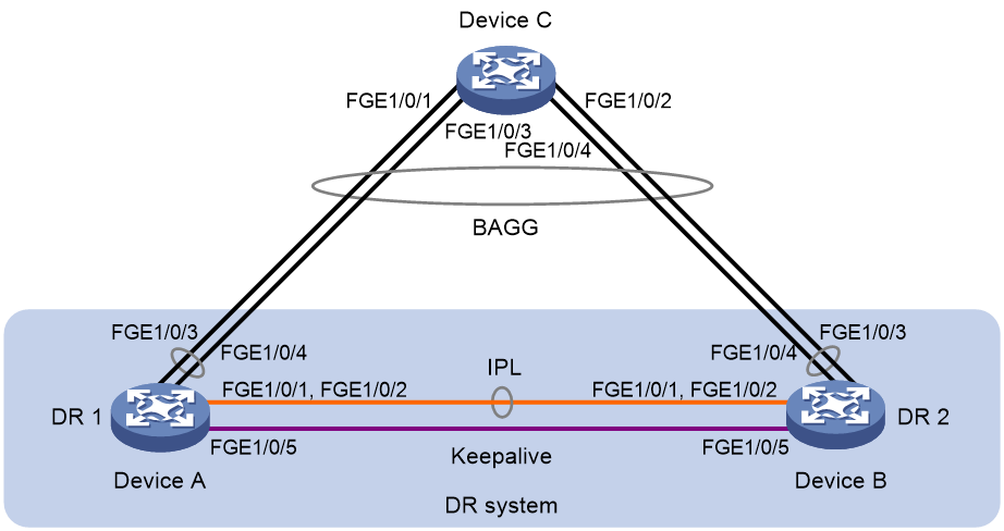
Network configuration
As shown in Figure 12, configure DRNI on Device A and Device B to establish a multichassis aggregate link with Device C.
Procedure
|
|
IMPORTANT: By default, interfaces on the device are disabled (in ADM or Administratively Down state). To have an interface operate, you must use the undo shutdown command to enable that interface. |
1. Configure Device A:
# Configure DR system settings.
<DeviceA> system-view
[DeviceA] drni system-mac 1-1-1
[DeviceA] drni system-number 1
[DeviceA] drni system-priority 123
# Configure DR keepalive packet parameters.
[DeviceA] drni keepalive ip destination 1.1.1.1 source 1.1.1.2
# Set the link mode of FortyGigE 1/0/5 to Layer 3, and assign the interface an IP address. The IP address will be used as the source IP address of keepalive packets.
[DeviceA] interface fortygige 1/0/5
[DeviceA-FortyGigE1/0/5] port link-mode route
[DeviceA-FortyGigE1/0/5] ip address 1.1.1.2 24
[DeviceA-FortyGigE1/0/5] quit
# Exclude the interface used for DR keepalive detection (FortyGigE 1/0/5) from the shutdown action by DRNI MAD.
[DeviceA] drni mad exclude interface fortygige 1/0/5
# Create Layer 2 dynamic aggregate interface Bridge-Aggregation 3.
[DeviceA] interface bridge-aggregation 3
[DeviceA-Bridge-Aggregation3] link-aggregation mode dynamic
[DeviceA-Bridge-Aggregation3] quit
# Assign FortyGigE 1/0/1 and FortyGigE 1/0/2 to aggregation group 3.
[DeviceA] interface fortygige 1/0/1
[DeviceA-FortyGigE1/0/1] port link-aggregation group 3
[DeviceA-FortyGigE1/0/1] quit
[DeviceA] interface fortygige 1/0/2
[DeviceA-FortyGigE1/0/2] port link-aggregation group 3
[DeviceA-FortyGigE1/0/2] quit
# Specify Bridge-Aggregation 3 as the IPP.
[DeviceA] interface bridge-aggregation 3
[DeviceA-Bridge-Aggregation3] port drni intra-portal-port 1
[DeviceA-Bridge-Aggregation3] quit
# Create Layer 2 dynamic aggregate interface Bridge-Aggregation 4.
[DeviceA] interface bridge-aggregation 4
[DeviceA-Bridge-Aggregation4] link-aggregation mode dynamic
[DeviceA-Bridge-Aggregation4] quit
# Assign FortyGigE 1/0/3 and FortyGigE 1/0/4 to aggregation group 4.
[DeviceA] interface fortygige 1/0/3
[DeviceA-FortyGigE1/0/3] port link-aggregation group 4
[DeviceA-FortyGigE1/0/3] quit
[DeviceA] interface fortygige 1/0/4
[DeviceA-FortyGigE1/0/4] port link-aggregation group 4
[DeviceA-FortyGigE1/0/4] quit
# Assign Bridge-Aggregation 4 to DR group 4.
[DeviceA] interface bridge-aggregation 4
[DeviceA-Bridge-Aggregation4] port drni group 4
[DeviceA-Bridge-Aggregation4] quit
2. Configure Device B:
# Configure DR system settings.
<DeviceB> system-view
[DeviceB] drni system-mac 1-1-1
[DeviceB] drni system-number 2
[DeviceB] drni system-priority 123
# Configure DR keepalive packet parameters.
[DeviceB] drni keepalive ip destination 1.1.1.2 source 1.1.1.1
# Set the link mode of FortyGigE 1/0/5 to Layer 3, and assign the interface an IP address. The IP address will be used as the source IP address of keepalive packets.
[DeviceB] interface fortygige 1/0/5
[DeviceB-FortyGigE1/0/5] port link-mode route
[DeviceB-FortyGigE1/0/5] ip address 1.1.1.1 24
[DeviceB-FortyGigE1/0/5] quit
# Exclude the interface used for DR keepalive detection (FortyGigE 1/0/5) from the shutdown action by DRNI MAD.
[DeviceB] drni mad exclude interface fortygige 1/0/5
# Create Layer 2 dynamic aggregate interface Bridge-Aggregation 3.
[DeviceB] interface bridge-aggregation 3
[DeviceB-Bridge-Aggregation3] link-aggregation mode dynamic
[DeviceB-Bridge-Aggregation3] quit
# Assign FortyGigE 1/0/1 and FortyGigE 1/0/2 to aggregation group 3.
[DeviceB] interface fortygige 1/0/1
[DeviceB-FortyGigE1/0/1] port link-aggregation group 3
[DeviceB-FortyGigE1/0/1] quit
[DeviceB] interface fortygige 1/0/2
[DeviceB-FortyGigE1/0/2] port link-aggregation group 3
[DeviceB-FortyGigE1/0/2] quit
# Specify Bridge-Aggregation 3 as the IPP.
[DeviceB] interface bridge-aggregation 3
[DeviceB-Bridge-Aggregation3] port drni intra-portal-port 1
[DeviceB-Bridge-Aggregation3] quit
# Create Layer 2 dynamic aggregate interface Bridge-Aggregation 4.
[DeviceB] interface bridge-aggregation 4
[DeviceB-Bridge-Aggregation4] link-aggregation mode dynamic
[DeviceB-Bridge-Aggregation4] quit
# Assign FortyGigE 1/0/3 and FortyGigE 1/0/4 to aggregation group 4.
[DeviceB] interface fortygige 1/0/3
[DeviceB-FortyGigE1/0/3] port link-aggregation group 4
[DeviceB-FortyGigE1/0/3] quit
[DeviceB] interface fortygige 1/0/4
[DeviceB-FortyGigE1/0/4] port link-aggregation group 4
[DeviceB-FortyGigE1/0/4] quit
# Assign Bridge-Aggregation 4 to DR group 4.
[DeviceB] interface bridge-aggregation 4
[DeviceB-Bridge-Aggregation4] port drni group 4
[DeviceB-Bridge-Aggregation4] quit
3. Configure Device C:
# Create Layer 2 dynamic aggregate interface Bridge-Aggregation 4.
<DeviceC> system-view
[DeviceC] interface bridge-aggregation 4
[DeviceC-Bridge-Aggregation4] link-aggregation mode dynamic
[DeviceC-Bridge-Aggregation4] quit
# Assign FortyGigE 1/0/1 through FortyGigE 1/0/4 to aggregation group 4.
[DeviceC] interface range fortygige 1/0/1 to fortygige 1/0/4
[DeviceC-if-range] port link-aggregation group 4
[DeviceC-if-range] quit
Verifying the configuration
# Verify that the keepalive link is working correctly on Device A.
[DeviceA] display drni keepalive
Neighbor keepalive link status: Up
Neighbor is alive for: 104 s, 16 ms
Keepalive packet transmission status:
Sent: Successful
Received: Successful
Last received keepalive packet information:
Source IP address: 1.1.1.1
Time: 2019/09/11 09:21:51
Action: Accept
Distributed relay keepalive parameters:
Destination IP address: 1.1.1.1
Source IP address: 1.1.1.2
Keepalive UDP port : 6400
Keepalive VPN name : N/A
Keepalive interval : 1000 ms
Keepalive timeout : 5 sec
Keepalive hold time: 3 sec
# Verify that the IPP and the DR interface are working correctly on Device A.
[DeviceA] display drni summary
Flags: A -- Aggregate interface down, B -- No peer DR interface configured
C -- Configuration consistency check failed
IPP: BAGG3
IPP state (cause): UP
Keepalive link state (cause): UP
DR interface information
DR interface DR group Local state (cause) Peer state Remaining down time (s)
BAGG4 4 UP UP -
[DeviceA] display drni verbose
Flags: A -- Home_Gateway, B -- Neighbor_Gateway, C -- Other_Gateway,
D -- IPP_Activity, E -- DRCP_Timeout, F -- Gateway_Sync,
G -- Port_Sync, H -- Expired
IPP/IPP ID: BAGG3/1
State: UP
Cause: -
Local DRCP flags/Peer DRCP flags: ABDFG/ABDFG
Local Selected ports (index): FGE1/0/1 (260), FGE1/0/2 (261)
Peer Selected ports indexes: 260, 261
DR interface/DR group ID: BAGG4/4
Local DR interface state: UP
Peer DR interface state: UP
DR group state: UP
Local DR interface down cause: -
Remaining DRNI DOWN time: -
Local DR interface LACP MAC: Config=0001-0001-0001, Effective=0001-0001-0001
Peer DR interface LACP MAC: Config=0001-0001-0001, Effective=0001-0001-0001
Local DR interface LACP priority: Config=123, Effective=123
Peer DR interface LACP priority: Config=123, Effective=123
Local DRCP flags/Peer DRCP flags: ABDFG/ABDFG
Local Selected ports (index): FGE1/0/3 (258), FGE1/0/4 (259)
Peer Selected ports indexes: 258, 259
# Verify that all member ports of aggregation group 4 are in Selected state on Device C, which indicates a successful link aggregation between the DR system and Device C.
[DeviceC] display link-aggregation verbose bridge-aggregation 4
Loadsharing Type: Shar -- Loadsharing, NonS -- Non-Loadsharing
Port Status: S -- Selected, U -- Unselected, I -- Individual
Port: A -- Auto port, M -- Management port, R -- Reference port
Flags: A -- LACP_Activity, B -- LACP_Timeout, C -- Aggregation,
D -- Synchronization, E -- Collecting, F -- Distributing,
G -- Defaulted, H -- Expired
Aggregate Interface: Bridge-Aggregation4
Creation Mode: Manual
Aggregation Mode: Dynamic
Loadsharing Type: Shar
Management VLANs: None
System ID: 0x8000, 2e56-cbae-0600
Local:
Port Status Priority Index Oper-Key Flag
FGE1/0/1(R) S 32768 1 1 {ACDEF}
FGE1/0/2 S 32768 2 1 {ACDEF}
FGE1/0/3 S 32768 3 1 {ACDEF}
FGE1/0/4 S 32768 4 1 {ACDEF}
Remote:
Actor Priority Index Oper-Key SystemID Flag
FGE1/0/1 32768 16387 40004 0x7b , 0001-0001-0001 {ACDEF}
FGE1/0/2 32768 16388 40004 0x7b , 0001-0001-0001 {ACDEF}
FGE1/0/3 32768 32771 40004 0x7b , 0001-0001-0001 {ACDEF}
FGE1/0/4 32768 32772 40004 0x7b , 0001-0001-0001 {ACDEF}
Example: Configuring Layer 3 gateways on a DR system
Network configuration
As shown in Figure 13:
· Configure Device A and Device B as a DR system to establish one multichassis aggregate link with Device C and one with Device D.
· Set up a keepalive link between FortyGigE 1/0/5 of Device A and FortyGigE 1/0/5 of Device B, and exclude the interfaces from the shutdown action by DRNI MAD.
· Configure two VRRP groups on Device A and Device B to provide gateway services for VLAN 100 and VLAN 200. Configure Device A as the master of the VRRP groups.
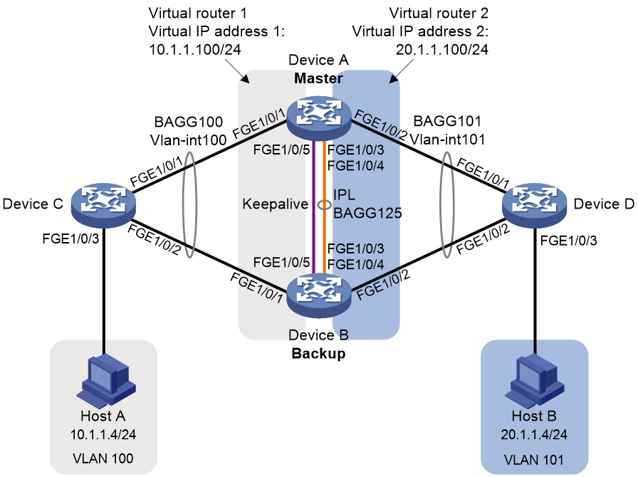
Procedure
|
|
IMPORTANT: By default, interfaces on the device are disabled (in ADM or Administratively Down state). To have an interface operate, you must use the undo shutdown command to enable that interface. |
1. Configure Device A:
# Configure DR system settings.
<DeviceA> system-view
[DeviceA] drni system-mac 1-1-1
[DeviceA] drni system-number 1
[DeviceA] drni system-priority 123
# Configure DR keepalive parameters.
[DeviceA] drni keepalive ip destination 1.1.1.2 source 1.1.1.1
# Set the link mode of FortyGigE 1/0/5 to Layer 3, and assign the interface an IP address. The IP address will be used as the source IP address of keepalive packets.
[DeviceA] interface fortygige 1/0/5
[DeviceA-FortyGigE1/0/5] port link-mode route
[DeviceA-FortyGigE1/0/5] ip address 1.1.1.1 24
[DeviceA-FortyGigE1/0/5] quit
# Exclude the interface used for DR keepalive detection (FortyGigE 1/0/5) from the shutdown action by DRNI MAD.
[DeviceA] drni mad exclude interface fortygige 1/0/5
# Create Layer 2 dynamic aggregate interface Bridge-Aggregation 125.
[DeviceA] interface bridge-aggregation 125
[DeviceA-Bridge-Aggregation125] link-aggregation mode dynamic
[DeviceA-Bridge-Aggregation125] quit
# Assign FortyGigE 1/0/3 and FortyGigE 1/0/4 to aggregation group 125.
[DeviceA] interface fortygige 1/0/3
[DeviceA-FortyGigE1/0/3] port link-aggregation group 125
[DeviceA-FortyGigE1/0/3] quit
[DeviceA] interface FortyGigE 1/0/4
[DeviceA-FortyGigE1/0/4] port link-aggregation group 125
[DeviceA-FortyGigE1/0/4] quit
# Specify Bridge-Aggregation 125 as the IPP.
[DeviceA] interface bridge-aggregation 125
[DeviceA-Bridge-Aggregation125] port drni intra-portal-port 1
[DeviceA-Bridge-Aggregation125] quit
# Create Layer 2 dynamic aggregate interface Bridge-Aggregation 100, and assign it to DR group 1.
[DeviceA] interface bridge-aggregation 100
[DeviceA-Bridge-Aggregation100] link-aggregation mode dynamic
[DeviceA-Bridge-Aggregation100] port drni group 1
[DeviceA-Bridge-Aggregation100] quit
# Assign FortyGigE 1/0/1 to aggregation group 100.
[DeviceA] interface fortygige 1/0/1
[DeviceA-FortyGigE1/0/1] port link-aggregation group 100
[DeviceA-FortyGigE1/0/1] quit
# Create Layer 2 dynamic aggregate interface Bridge-Aggregation 101, and assign it to DR group 2.
[DeviceA] interface bridge-aggregation 101
[DeviceA-Bridge-Aggregation101] link-aggregation mode dynamic
[DeviceA-Bridge-Aggregation101] port drni group 2
[DeviceA-Bridge-Aggregation101] quit
# Assign FortyGigE 1/0/2 to aggregation group 101.
[DeviceA] interface fortygige 1/0/2
[DeviceA-FortyGigE1/0/2] port link-aggregation group 101
[DeviceA-FortyGigE1/0/2] quit
# Create VLAN 100 and VLAN 101.
[DeviceA] vlan 100
[DeviceA-vlan100] quit
[DeviceA] vlan 101
[DeviceA-vlan101] quit
# Set the link type of Bridge-Aggregation 100 to trunk, and assign it to VLAN 100.
[DeviceA] interface bridge-aggregation 100
[DeviceA-Bridge-Aggregation100] port link-type trunk
[DeviceA-Bridge-Aggregation100] port trunk permit vlan 100
[DeviceA-Bridge-Aggregation100] quit
# Set the link type of Bridge-Aggregation 101 to trunk, and assign it to VLAN 101.
[DeviceA] interface bridge-aggregation 101
[DeviceA-Bridge-Aggregation101] port link-type trunk
[DeviceA-Bridge-Aggregation101] port trunk permit vlan 101
[DeviceA-Bridge-Aggregation101] quit
# Create VLAN-interface 100 and VLAN-interface 101, and assign IP addresses to them.
[DeviceA] interface vlan-interface 100
[DeviceA-vlan-interface100] ip address 10.1.1.1 24
[DeviceA-vlan-interface100] quit
[DeviceA] interface vlan-interface 101
[DeviceA-vlan-interface101] ip address 20.1.1.1 24
[DeviceA-vlan-interface101] quit
# Exclude VLAN-interface 100 and VLAN-interface 101 from the shutdown action by DRNI MAD.
[DeviceA] drni mad exclude interface vlan-interface 100
[DeviceA] drni mad exclude interface vlan-interface 101
# Configure OSPF.
[DeviceA] ospf
[DeviceA-ospf-1] import-route direct
[DeviceA-ospf-1] area 0
[DeviceA-ospf-1-area-0.0.0.0] network 10.1.1.0 0.0.0.255
[DeviceA-ospf-1-area-0.0.0.0] network 20.1.1.0 0.0.0.255
[DeviceA-ospf-1-area-0.0.0.0] quit
[DeviceA-ospf-1] quit
# Create VRRP group 1 on VLAN-interface 100 and set its virtual IP address to 10.1.1.100.
[DeviceA] interface vlan-interface 100
[DeviceA-Vlan-interface100] vrrp vrid 1 virtual-ip 10.1.1.100
# Set the priority of Device A (primary DR device) to 200 for it to become the master in VRRP group 1.
[DeviceA-Vlan-interface100] vrrp vrid 1 priority 200
[DeviceA-Vlan-interface100] quit
# Create VRRP group 2 on VLAN-interface 101 and set its virtual IP address to 20.1.1.100.
[DeviceA] interface vlan-interface 101
[DeviceA-Vlan-interface101] vrrp vrid 2 virtual-ip 20.1.1.100
# Set the priority of Device A (primary DR device) to 200 for it to become the master in VRRP group 2.
[DeviceA-Vlan-interface101] vrrp vrid 2 priority 200
[DeviceA-Vlan-interface101] quit
2. Configure Device B:
# Configure DR system settings.
<DeviceB> system-view
[DeviceB] drni system-mac 1-1-1
[DeviceB] drni system-number 2
[DeviceB] drni system-priority 123
# Configure DR keepalive parameters.
[DeviceB] drni keepalive ip destination 1.1.1.1 source 1.1.1.2
# Set the link mode of FortyGigE 1/0/5 to Layer 3, and assign the interface an IP address. The IP address will be used as the source IP address of keepalive packets.
[DeviceB] interface fortygige 1/0/5
[DeviceB-FortyGigE1/0/5] port link-mode route
[DeviceB-FortyGigE1/0/5] ip address 1.1.1.2 24
[DeviceB-FortyGigE1/0/5] quit
# Exclude the interface used for DR keepalive detection (FortyGigE 1/0/5) from the shutdown action by DRNI MAD.
[DeviceB] drni mad exclude interface fortygige 1/0/5
# Create Layer 2 dynamic aggregate interface Bridge-Aggregation 125.
[DeviceB] interface bridge-aggregation 125
[DeviceB-Bridge-Aggregation125] link-aggregation mode dynamic
[DeviceB-Bridge-Aggregation125] quit
# Assign FortyGigE 1/0/3 and FortyGigE 1/0/4 to aggregation group 125.
[DeviceB] interface fortygige 1/0/3
[DeviceB-FortyGigE1/0/3] port link-aggregation group 125
[DeviceB-FortyGigE1/0/3] quit
[DeviceB] interface fortygige 1/0/4
[DeviceB-FortyGigE1/0/4] port link-aggregation group 125
[DeviceB-FortyGigE1/0/4] quit
# Specify Bridge-Aggregation 125 as the IPP.
[DeviceB] interface bridge-aggregation 125
[DeviceB-Bridge-Aggregation125] port drni intra-portal-port 1
[DeviceB-Bridge-Aggregation125] quit
# Create Layer 2 dynamic aggregate interface Bridge-Aggregation 100, and assign it to DR group 1.
[DeviceB] interface bridge-aggregation 100
[DeviceB-Bridge-Aggregation100] link-aggregation mode dynamic
[DeviceB-Bridge-Aggregation100] port drni group 1
[DeviceB-Bridge-Aggregation100] quit
# Assign FortyGigE 1/0/1 to aggregation group 100.
[DeviceB] interface fortygige 1/0/1
[DeviceB-FortyGigE1/0/1] port link-aggregation group 100
[DeviceB-FortyGigE1/0/1] quit
# Create Layer 2 dynamic aggregate interface Bridge-Aggregation 101, and assign it to DR group 2.
[DeviceB] interface bridge-aggregation 101
[DeviceB-Bridge-Aggregation101] link-aggregation mode dynamic
[DeviceB-Bridge-Aggregation101] port drni group 2
[DeviceB-Bridge-Aggregation101] quit
# Assign FortyGigE 1/0/2 to aggregation group 101.
[DeviceB] interface fortygige 1/0/2
[DeviceB-FortyGigE1/0/2] port link-aggregation group 101
[DeviceB-FortyGigE1/0/2] quit
# Create VLAN 100 and VLAN 101.
[DeviceB] vlan 100
[DeviceB-vlan100] quit
[DeviceB] vlan 101
[DeviceB-vlan101] quit
# Set the link type of Bridge-Aggregation 100 to trunk, and assign it to VLAN 100.
[DeviceB] interface bridge-aggregation 100
[DeviceB-Bridge-Aggregation100] port link-type trunk
[DeviceB-Bridge-Aggregation100] port trunk permit vlan 100
[DeviceB-Bridge-Aggregation100] quit
# Set the link type of Bridge-Aggregation 101 to trunk, and assign it to VLAN 101.
[DeviceB] interface bridge-aggregation 101
[DeviceB-Bridge-Aggregation101] port link-type trunk
[DeviceB-Bridge-Aggregation101] port trunk permit vlan 101
[DeviceB-Bridge-Aggregation101] quit
# Create VLAN-interface 100 and VLAN-interface 101, and assign IP addresses to them.
[DeviceB] interface vlan-interface 100
[DeviceB-vlan-interface100] ip address 10.1.1.2 24
[DeviceB-vlan-interface100] quit
[DeviceB] interface vlan-interface 101
[DeviceB-vlan-interface101] ip address 20.1.1.2 24
[DeviceB-vlan-interface101] quit
# Exclude VLAN-interface 100 and VLAN-interface 101 from the shutdown action by DRNI MAD.
[DeviceB] drni mad exclude interface vlan-interface 100
[DeviceB] drni mad exclude interface vlan-interface 101
# Configure OSPF.
[DeviceB] ospf
[DeviceB-ospf-1] import-route direct
[DeviceB-ospf-1] area 0
[DeviceB-ospf-1-area-0.0.0.0] network 10.1.1.0 0.0.0.255
[DeviceB-ospf-1-area-0.0.0.0] network 20.1.1.0 0.0.0.255
[DeviceB-ospf-1-area-0.0.0.0] quit
[DeviceB-ospf-1] quit
# Create VRRP group 1 on VLAN-interface 100 and set its virtual IP address to 10.1.1.100.
[DeviceB] interface vlan-interface 100
[DeviceB-Vlan-interface100] vrrp vrid 1 virtual-ip 10.1.1.100
[DeviceB-Vlan-interface100] quit
# Create VRRP group 2 on VLAN-interface 101 and set its virtual IP address to 20.1.1.100.
[DeviceB] interface vlan-interface 101
[DeviceB-Vlan-interface101] vrrp vrid 2 virtual-ip 20.1.1.100
[DeviceB-Vlan-interface101] quit
3. Configure Device C:
# Create Layer 2 dynamic aggregate interface Bridge-Aggregation 100.
<DeviceC> system-view
[DeviceC] interface bridge-aggregation 100
[DeviceC-Bridge-Aggregation100] link-aggregation mode dynamic
[DeviceC-Bridge-Aggregation100] quit
# Assign FortyGigE 1/0/1 and FortyGigE 1/0/2 to aggregation group 100.
[DeviceC] interface range fortygige 1/0/1 to fortygige 1/0/2
[DeviceC-if-range] port link-aggregation group 100
[DeviceC-if-range] quit
# Create VLAN 100.
[DeviceC] vlan 100
[DeviceC-vlan100] quit
# Set the link type of Bridge-Aggregation 100 to trunk, and assign it to VLAN 100.
[DeviceC] interface bridge-aggregation 100
[DeviceC-Bridge-Aggregation100] port link-type trunk
[DeviceC-Bridge-Aggregation100] port trunk permit vlan 100
[DeviceC-Bridge-Aggregation100] quit
# Set the link type of FortyGigE 1/0/3 to trunk, and assign it to VLAN 100.
[DeviceC] interface fortygige 1/0/3
[DeviceC-FortyGigE1/0/3] port link-type trunk
[DeviceC-FortyGigE1/0/3] port trunk permit vlan 100
[DeviceC-FortyGigE1/0/3] quit
# Create VLAN-interface 100, and assign it an IP address.
[DeviceC] interface vlan-interface 100
[DeviceC-vlan-interface100] ip address 10.1.1.3 24
[DeviceC-vlan-interface100] quit
# Configure OSPF.
[DeviceC] ospf
[DeviceC-ospf-1] import-route direct
[DeviceC-ospf-1] area 0
[DeviceC-ospf-1-area-0.0.0.0] network 10.1.1.0 0.0.0.255
[DeviceC-ospf-1-area-0.0.0.0] quit
[DeviceC-ospf-1] quit
4. Configure Device D:
# Create Layer 2 dynamic aggregate interface Bridge-Aggregation 101.
<DeviceD> system-view
[DeviceD] interface bridge-aggregation 101
[DeviceD-Bridge-Aggregation101] link-aggregation mode dynamic
[DeviceD-Bridge-Aggregation101] quit
# Assign FortyGigE 1/0/1 and FortyGigE 1/0/2 to aggregation group 101.
[DeviceD] interface range fortygige 1/0/1 to fortygige 1/0/2
[DeviceD-if-range] port link-aggregation group 101
[DeviceD-if-range] quit
# Create VLAN 101.
[DeviceD] vlan 101
[DeviceD-vlan101] quit
# Set the link type of Bridge-Aggregation 101 to trunk, and assign it to VLAN 101.
[DeviceD] interface bridge-aggregation 101
[DeviceD-Bridge-Aggregation101] port link-type trunk
[DeviceD-Bridge-Aggregation101] port trunk permit vlan 101
[DeviceD-Bridge-Aggregation101] quit
# Set the link type of FortyGigE 1/0/3 to trunk, and assign it to VLAN 101.
[DeviceD] interface fortygige 1/0/3
[DeviceD-FortyGigE1/0/3] port link-type trunk
[DeviceD-FortyGigE1/0/3] port trunk permit vlan 101
[DeviceD-FortyGigE1/0/3] quit
# Create VLAN-interface 101, and assign it an IP address.
[DeviceD] interface vlan-interface 101
[DeviceD-vlan-interface101] ip address 20.1.1.3 24
[DeviceD-vlan-interface101] quit
# Configure OSPF.
[DeviceD] ospf
[DeviceD-ospf-1] import-route direct
[DeviceD-ospf-1] area 0
[DeviceD-ospf-1-area-0.0.0.0] network 20.1.1.0 0.0.0.255
[DeviceD-ospf-1-area-0.0.0.0] quit
[DeviceD-ospf-1] quit
Verifying the configuration
# Verify that Device A has formed a DR system with Device B.
[DeviceA] display drni summary
Flags: A -- Aggregate interface down, B -- No peer DR interface configured
C -- Configuration consistency check failed
IPP: BAGG125
IPP state (cause): UP
Keepalive link state (cause): UP
DR interface information
DR interface DR group Local state (cause) Peer state Remaining down time(s)
BAGG100 1 UP UP -
BAGG101 2 UP UP -
[DeviceA] display drni verbose
Flags: A -- Home_Gateway, B -- Neighbor_Gateway, C -- Other_Gateway,
D -- IPP_Activity, E -- DRCP_Timeout, F -- Gateway_Sync,
G -- Port_Sync, H -- Expired
IPP/IPP ID: BAGG125/1
State: UP
Cause: -
Local DRCP flags/Peer DRCP flags: ABDFG/ABDFG
Local Selected ports (index): FGE1/0/3 (260), FGE1/0/4 (261)
Peer Selected ports indexes: 260, 261
DR interface/DR group ID: BAGG100/1
Local DR interface state: UP
Peer DR interface state: UP
DR group state: UP
Local DR interface down cause: -
Remaining DRNI DOWN time: -
Local DR interface LACP MAC: Config=N/A, Effective=0001-0001-0001
Peer DR interface LACP MAC: Config=N/A, Effective=0001-0001-0001
Local DR interface LACP priority: Config=32768, Effective=123
Peer DR interface LACP priority: Config=32768, Effective=123
Local DRCP flags/Peer DRCP flags: ABDFG/ABDFG
Local Selected ports (index): FGE1/0/1 (258)
Peer Selected ports indexes: 258
DR interface/DR group ID: BAGG101/2
Local DR interface state: UP
Peer DR interface state: UP
DR group state: UP
Local DR interface down cause: -
Remaining DRNI DOWN time: -
Local DR interface LACP MAC: Config=N/A, Effective=0001-0001-0001
Peer DR interface LACP MAC: Config=N/A, Effective=0001-0001-0001
Local DR interface LACP priority: Config=32768, Effective=123
Peer DR interface LACP priority: Config=32768, Effective=123
Local DRCP flags/Peer DRCP flags: ABDFG/ABDFG
Local Selected ports (index): FGE1/0/2 (259)
Peer Selected ports indexes: 259
# Verify that Device C and Device D have correctly set up aggregate links with the DR system.
[DeviceC] display link-aggregation verbose
Loadsharing Type: Shar -- Loadsharing, NonS -- Non-Loadsharing
Port Status: S -- Selected, U -- Unselected, I -- Individual
Port: A -- Auto port, M -- Management port, R -- Reference port
Flags: A -- LACP_Activity, B -- LACP_Timeout, C -- Aggregation,
D -- Synchronization, E -- Collecting, F -- Distributing,
G -- Defaulted, H -- Expired
Aggregate Interface: Bridge-Aggregation100
Creation Mode: Manual
Aggregation Mode: Dynamic
Loadsharing Type: Shar
Management VLANs: None
System ID: 0x8000, a03b-0694-0300
Local:
Port Status Priority Index Oper-Key Flag
FGE1/0/1 S 32768 1 1 {ACDEF}
FGE1/0/2 S 32768 2 1 {ACDEF}
Remote:
Actor Priority Index Oper-Key SystemID Flag
FGE1/0/1(R) 32768 16386 40001 0x7b , 0001-0001-0001 {ACDEF}
FGE1/0/2 32768 32770 40001 0x7b , 0001-0001-0001 {ACDEF}
[DeviceD] display link-aggregation verbose
Loadsharing Type: Shar -- Loadsharing, NonS -- Non-Loadsharing
Port Status: S -- Selected, U -- Unselected, I -- Individual
Port: A -- Auto port, M -- Management port, R -- Reference port
Flags: A -- LACP_Activity, B -- LACP_Timeout, C -- Aggregation,
D -- Synchronization, E -- Collecting, F -- Distributing,
G -- Defaulted, H -- Expired
Aggregate Interface: Bridge-Aggregation101
Creation Mode: Manual
Aggregation Mode: Dynamic
Loadsharing Type: Shar
Management VLANs: None
System ID: 0x8000, a03b-0d51-0400
Local:
Port Status Priority Index Oper-Key Flag
FGE1/0/1 S 32768 1 1 {ACDEF}
FGE1/0/2 S 32768 2 1 {ACDEF}
Remote:
Actor Priority Index Oper-Key SystemID Flag
FGE1/0/1(R) 32768 16387 40002 0x7b , 0001-0001-0001 {ACDEF}
FGE1/0/2 32768 32771 40002 0x7b , 0001-0001-0001 {ACDEF}
# Verify that Device A is the master in VRRP group 1 and VRRP group 2.
[DeviceA] display vrrp
IPv4 Virtual Router Information:
Running mode : Standard
Total number of virtual routers : 2
Interface VRID State Running Adver Auth Virtual
Pri Timer Type IP
----------------------------------------------------------------------------
Vlan100 1 Master 200 100 None 10.1.1.100
Vlan101 2 Master 200 100 None 20.1.1.100
[DeviceB] display vrrp
IPv4 Virtual Router Information:
Running mode : Standard
Total number of virtual routers : 2
Interface VRID State Running Adver Auth Virtual
Pri Timer Type IP
----------------------------------------------------------------------------
Vlan100 1 Backup 100 100 None 10.1.1.100
Vlan101 2 Backup 100 100 None 20.1.1.100
# Verify that Device C and Device D have established OSPF neighbor relationships with Device A and Device B.
[DeviceC] display ospf peer
OSPF Process 1 with Router ID 10.1.1.3
Neighbor Brief Information
Area: 0.0.0.0
Router ID Address Pri Dead-Time State Interface
20.1.1.1 10.1.1.1 1 37 Full/DR Vlan100
20.1.1.2 10.1.1.2 1 32 Full/BDR Vlan100
[DeviceD] display ospf peer
OSPF Process 1 with Router ID 20.1.1.3
Neighbor Brief Information
Area: 0.0.0.0
Router ID Address Pri Dead-Time State Interface
20.1.1.1 20.1.1.1 1 38 Full/DR Vlan101
20.1.1.2 20.1.1.2 1 37 Full/BDR Vlan101
# Verify that Host A and Host B can ping each other. (Details not shown.)
Example: Configure dual-active gateways on a DR system
Network configuration
As shown in Figure 14, set up a DR system with Device A and Device B and configure dual-active gateways for the servers on Device A and Device B.
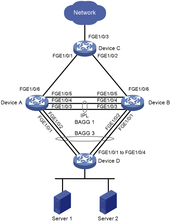
Procedure
1. Configure Device A:
# Configure DR system settings.
<DeviceA> system-view
[DeviceA] drni system-mac 2-2-2
[DeviceA] drni system-number 1
[DeviceA] drni system-priority 123
# Configure DR keepalive parameters.
[DeviceA] drni keepalive ip destination 21.1.1.2 source 21.1.1.1
# Set the link mode of FortyGigE 1/0/5 to Layer 3, and assign the interface IPv4 and IPv6 addresses. The IPv4 address will be used as the source IP address of keepalive packets.
[DeviceA] interface fortygige 1/0/5
[DeviceA-FortyGigE1/0/5] port link-mode route
[DeviceA-FortyGigE1/0/5] ip address 21.1.1.1 24
[DeviceA-FortyGigE1/0/5] ipv6 address 21::1 64
[DeviceA-FortyGigE1/0/5] quit
# Exclude the interface used for DR keepalive detection (FortyGigE 1/0/5) from the shutdown action by DRNI MAD.
[DeviceA] drni mad exclude interface fortygige 1/0/5
# Create Layer 2 dynamic aggregate interface Bridge-Aggregation 1.
[DeviceA] interface bridge-aggregation 1
[DeviceA-Bridge-Aggregation1] link-aggregation mode dynamic
[DeviceA-Bridge-Aggregation1] quit
# Assign FortyGigE 1/0/3 and FortyGigE 1/0/4 to aggregation group 1.
[DeviceA] interface fortygige 1/0/3
[DeviceA-FortyGigE1/0/3] port link-aggregation group 1
[DeviceA-FortyGigE1/0/3] quit
[DeviceA] interface fortygige 1/0/4
[DeviceA-FortyGigE1/0/4] port link-aggregation group 1
[DeviceA-FortyGigE1/0/4] quit
# Configure Bridge-Aggregation 1 as the IPP.
[DeviceA] interface bridge-aggregation 1
[DeviceA-Bridge-Aggregation1] port drni intra-portal-port 1
[DeviceA-Bridge-Aggregation1] quit
# Create Layer 2 dynamic aggregate interface Bridge-Aggregation 3, and assign it to DR group 1.
[DeviceA] interface bridge-aggregation 3
[DeviceA-Bridge-Aggregation3] link-aggregation mode dynamic
[DeviceA-Bridge-Aggregation3] port drni group 1
[DeviceA-Bridge-Aggregation3] quit
# Assign FortyGigE 1/0/1 and FortyGigE 1/0/2 to aggregation group 3.
[DeviceA] interface fortygige 1/0/1
[DeviceA-FortyGigE1/0/1] port link-aggregation group 3
[DeviceA-FortyGigE1/0/1] quit
[DeviceA] interface fortygige 1/0/2
[DeviceA-FortyGigE1/0/2] port link-aggregation group 3
[DeviceA-FortyGigE1/0/2] quit
# Create VLAN 102 and VLAN 103.
[DeviceA] vlan 102 103
# Set the link type of Bridge-Aggregation 3 to trunk, and assign it to VLAN 102 and VLAN 103.
[DeviceA] interface bridge-aggregation 3
[DeviceA-Bridge-Aggregation3] port link-type trunk
[DeviceA-Bridge-Aggregation3] port trunk permit vlan 102 103
[DeviceA-Bridge-Aggregation3] quit
# Create VLAN-interface 102 and assign it an IPv4 address and an IPv6 address for the interface to act as an IPv4 and IPv6 gateway.
[DeviceA] interface vlan-interface 102
[DeviceA-Vlan-interface102] ip address 10.102.0.1 255.255.255.0
[DeviceA-Vlan-interface102] ipv6 address 10:102::1 64
# Assign DRNI virtual IPv4 and IPv6 addresses to VLAN-interface 102 for Device A to establish OSPF and OSPFv3 neighbor relationships with Device D.
[DeviceA-Vlan-interface102] port drni virtual-ip 10.102.0.3 24 active
[DeviceA-Vlan-interface102] port drni ipv6 virtual-ip FE80::2 link-local
# Assign a MAC address to VLAN-interface 102.
[DeviceA-Vlan-interface102] mac-address 3-3-3
[DeviceA-Vlan-interface102] quit
# Exclude VLAN-interface 102 from the shutdown action by DRNI MAD.
[DeviceA] drni mad exclude interface vlan-interface 102
# Create VLAN-interface 103 and assign it an IPv4 address and an IPv6 address for the interface to act as an IPv4 and IPv6 gateway.
[DeviceA] interface vlan-interface 103
[DeviceA-Vlan-interface103] ip address 10.103.0.1 24
[DeviceA-Vlan-interface103] ipv6 address 10:103::1 64
# Assign DRNI virtual IPv4 and IPv6 addresses to VLAN-interface 103 for Device A to establish BGP and BGP4+ peer relationships with Device D.
[DeviceA-Vlan-interface103] port drni virtual-ip 10.103.0.3 24 active
[DeviceA-Vlan-interface103] port drni ipv6 virtual-ip 10:103::3 64 active
# Assign a MAC address to VLAN-interface 103.
[DeviceA-Vlan-interface103] mac-address 4-4-4
[DeviceA-Vlan-interface103] quit
# Exclude VLAN-interface 103 from the shutdown action by DRNI MAD.
[DeviceA] drni mad exclude interface vlan-interface 103
# Assign an IPv4 address and an IPv6 address to uplink interface FortyGigE 1/0/6.
[DeviceA] interface fortygige 1/0/6
[DeviceA-FortyGigE1/0/6] port link-mode route
[DeviceA-FortyGigE1/0/6] ip address 32.1.1.1 24
[DeviceA-FortyGigE1/0/6] ipv6 address 32:1::1 64
[DeviceA-FortyGigE1/0/6] quit
# Configure OSPF.
[DeviceA] ospf 1 router-id 11.1.1.1
[DeviceA-ospf-1] area 0
[DeviceA-ospf-1-area-0.0.0.0] quit
[DeviceA-ospf-1] quit
[DeviceA] interface vlan-interface 102
[DeviceA-Vlan-interface102] ospf 1 area 0
[DeviceA-Vlan-interface102] ospf peer sub-address enable 10.102.0.3
[DeviceA-Vlan-interface102] quit
[DeviceA] interface fortygige 1/0/6
[DeviceA-FortyGigE1/0/6] ospf 1 area 0
[DeviceA-FortyGigE1/0/6] quit
# Configure OSPFv3.
[DeviceA] ospfv3 1
[DeviceA-ospfv3-1] router-id 10.1.1.1
[DeviceA-ospfv3-1] area 0
[DeviceA-ospfv3-1-area-0.0.0.0] quit
[DeviceA-ospfv3-1] quit
[DeviceA] interface vlan-interface 102
[DeviceA-Vlan-interface102] ospfv3 1 area 0
[DeviceA-Vlan-interface102] quit
[DeviceA] interface fortygige 1/0/6
[DeviceA-FortyGigE1/0/6] ospfv3 1 area 0
[DeviceA-FortyGigE1/0/6] quit
# Configure BGP.
[DeviceA] bgp 100
[DeviceA-bgp-default] router-id 12.1.1.1
[DeviceA-bgp-default] peer 32.1.1.2 as-number 100
[DeviceA-bgp-default] peer 10.103.0.2 as-number 100
[DeviceA-bgp-default] peer 10.103.0.2 source-address 10.103.0.3
[DeviceA-bgp-default] address-family ipv4
[DeviceA-bgp-default-ipv4] peer 10.103.0.2 enable
[DeviceA-bgp-default-ipv4] network 10.103.0.0 255.255.255.0
[DeviceA-bgp-default-ipv4] peer 32.1.1.2 enable
[DeviceA-bgp-default-ipv4] network 32.1.1.0 255.255.255.0
[DeviceA-bgp-default-ipv4] quit
# Configure BGP4+.
[DeviceA-bgp-default] peer 32:1::2 as-number 100
[DeviceA-bgp-default] peer 10:103::2 as-number 100
[DeviceA-bgp-default] peer 10:103::2 source-address 10:103::3
[DeviceA-bgp-default] address-family ipv6
[DeviceA-bgp-default-ipv6] peer 10:103::2 enable
[DeviceA-bgp-default-ipv6] network 10:103::2 64
[DeviceA-bgp-default-ipv6] peer 32:1::2 enable
[DeviceA-bgp-default-ipv6] network 32:1::2 64
[DeviceA-bgp-default-ipv6] quit
2. Configure Device B:
# Configure DR system settings.
<DeviceB> system-view
[DeviceB] drni system-mac 2-2-2
[DeviceB] drni system-number 2
[DeviceB] drni system-priority 123
# Configure DR keepalive parameters.
[DeviceB] drni keepalive ip destination 21.1.1.1 source 21.1.1.2
# Set the link mode of FortyGigE 1/0/5 to Layer 3, and assign the interface IPv4 and IPv6 addresses. The IPv4 address will be used as the source IP address of keepalive packets.
[DeviceB] interface fortygige 1/0/5
[DeviceB-FortyGigE1/0/5] port link-mode route
[DeviceB-FortyGigE1/0/5] ip address 21.1.1.2 255.255.255.0
[DeviceB-FortyGigE1/0/5] ipv6 address 21::2 64
[DeviceB-FortyGigE1/0/5] quit
# Exclude the interface used for DR keepalive detection (FortyGigE 1/0/5) from the shutdown action by DRNI MAD.
[DeviceB] drni mad exclude interface fortygige 1/0/5
# Create Layer 2 dynamic aggregate interface Bridge-Aggregation 1.
[DeviceB] interface bridge-aggregation 1
[DeviceB-Bridge-Aggregation1] link-aggregation mode dynamic
[DeviceB-Bridge-Aggregation1] quit
# Assign FortyGigE 1/0/3 and FortyGigE 1/0/4 to aggregation group 1.
[DeviceB] interface fortygige 1/0/3
[DeviceB-FortyGigE1/0/3] port link-aggregation group 1
[DeviceB-FortyGigE1/0/3] quit
[DeviceB] interface fortygige 1/0/4
[DeviceB-FortyGigE1/0/4] port link-aggregation group 1
[DeviceB-FortyGigE1/0/4] quit
# Configure Bridge-Aggregation 1 as the IPP.
[DeviceB] interface bridge-aggregation 1
[DeviceB-Bridge-Aggregation1] port drni intra-portal-port 1
[DeviceB-Bridge-Aggregation1] quit
# Create Layer 2 dynamic aggregate interface Bridge-Aggregation 3, and assign it to DR group 1.
[DeviceB] interface bridge-aggregation 3
[DeviceB-Bridge-Aggregation3] link-aggregation mode dynamic
[DeviceB-Bridge-Aggregation3] port drni group 1
[DeviceB-Bridge-Aggregation3] quit
# Assign FortyGigE 1/0/1 and FortyGigE 1/0/2 to aggregation group 3.
[DeviceB] interface fortygige 1/0/1
[DeviceB-FortyGigE1/0/1] port link-aggregation group 3
[DeviceB-FortyGigE1/0/1] quit
[DeviceB] interface fortygige 1/0/2
[DeviceB-FortyGigE1/0/2] port link-aggregation group 3
[DeviceB-FortyGigE1/0/2] quit
# Create VLAN 102 and VLAN 103.
[DeviceB] vlan 102 103
# Set the link type of Bridge-Aggregation 3 to trunk, and assign it to VLAN 102 and VLAN 103.
[DeviceB] interface bridge-aggregation 3
[DeviceB-Bridge-Aggregation3] port link-type trunk
[DeviceB-Bridge-Aggregation3] port trunk permit vlan 102 103
[DeviceB-Bridge-Aggregation3] quit
# Create VLAN-interface 102 and assign it an IPv4 address and an IPv6 address for the interface to act as an IPv4 and IPv6 gateway.
[DeviceB] interface vlan-interface 102
[DeviceB-Vlan-interface102] ip address 10.102.0.1 24
[DeviceB-Vlan-interface102] ipv6 address 10:102::1 64
# Assign DRNI virtual IPv4 and IPv6 addresses to VLAN-interface 102 for Device A to establish OSPF and OSPFv3 neighbor relationships with Device D.
[DeviceB-Vlan-interface102] port drni virtual-ip 10.102.0.4 24 active
[DeviceB-Vlan-interface102] port drni ipv6 virtual-ip FE80::4 link-local
# Assign a MAC address to VLAN-interface 102.
[DeviceB-Vlan-interface102] mac-address 3-3-3
[DeviceB-Vlan-interface102] quit
# Exclude VLAN-interface 102 from the shutdown action by DRNI MAD.
[DeviceB] drni mad exclude interface vlan-interface 102
# Create VLAN-interface 103 and assign it an IPv4 address and an IPv6 address for the interface to act as an IPv4 and IPv6 gateway.
[DeviceB] interface vlan-interface 103
[DeviceB-Vlan-interface103] ip address 10.103.0.1 24
[DeviceB-Vlan-interface103] ipv6 address 10:103::1 64
# Assign DRNI virtual IPv4 and IPv6 addresses to VLAN-interface 103 for Device A to establish BGP and BGP4+ peer relationships with Device D.
[DeviceB-Vlan-interface103] port drni virtual-ip 10.103.0.4 24 active
[DeviceB-Vlan-interface103] port drni ipv6 virtual-ip 10:103::4 64 active
# Assign a MAC address to VLAN-interface 103.
[DeviceB-Vlan-interface103] mac-address 4-4-4
[DeviceB-Vlan-interface103] quit
# Exclude VLAN-interface 103 from the shutdown action by DRNI MAD.
[DeviceB] drni mad exclude interface vlan-interface 103
# Assign an IPv4 address and an IPv6 address to uplink interface FortyGigE 1/0/6.
[DeviceB] interface fortygige 1/0/6
[DeviceB-FortyGigE1/0/6] port link-mode route
[DeviceB-FortyGigE1/0/6] ip address 33.1.1.1 24
[DeviceB-FortyGigE1/0/6] ipv6 address 33:1::1 64
[DeviceB-FortyGigE1/0/6] quit
# Configure OSPF.
[DeviceB] ospf 1 router-id 11.1.1.2
[DeviceB-ospf-1] area 0
[DeviceB-ospf-1-area-0.0.0.0] quit
[DeviceB-ospf-1] quit
[DeviceB] interface vlan-interface 102
[DeviceB-Vlan-interface102] ospf 1 area 0
[DeviceB-Vlan-interface102] ospf peer sub-address enable 10.102.0.4
[DeviceB-Vlan-interface102] quit
[DeviceB] interface fortygige 1/0/6
[DeviceB-FortyGigE1/0/6] ospf 1 area 0
[DeviceB-FortyGigE1/0/6] quit
# Configure OSPFv3.
[DeviceB] ospfv3 1
[DeviceB-ospfv3-1] router-id 10.1.1.2
[DeviceB-ospfv3-1] area 0
[DeviceB-ospfv3-1-area-0.0.0.0] quit
[DeviceB-ospfv3-1] quit
[DeviceB] interface vlan-interface 102
[DeviceB-Vlan-interface102] ospfv3 1 area 0
[DeviceB-Vlan-interface102] quit
[DeviceB] interface fortygige 1/0/6
[DeviceB-FortyGigE1/0/6] ospfv3 1 area 0
[DeviceB-FortyGigE1/0/6] quit
# Configure BGP.
[DeviceB] bgp 100
[DeviceB-bgp-default] router-id 12.1.1.2
[DeviceB-bgp-default] peer 33.1.1.2 as-number 100
[DeviceB-bgp-default] peer 10.103.0.2 as-number 100
[DeviceB-bgp-default] peer 10.103.0.2 source-address 10.103.0.4
[DeviceB-bgp-default] address-family ipv4
[DeviceB-bgp-default-ipv4] peer 10.103.0.2 enable
[DeviceB-bgp-default-ipv4] network 10.103.0.0 255.255.255.0
[DeviceB-bgp-default-ipv4] peer 33.1.1.2 enable
[DeviceB-bgp-default-ipv4] network 33.1.1.0 255.255.255.0
[DeviceB-bgp-default-ipv4] quit
# Configure BGP4+.
[DeviceB-bgp-default] peer 33:1::2 as-number 100
[DeviceB-bgp-default] peer 10:103::2 as-number 100
[DeviceB-bgp-default] peer 10:103::2 source-address 10:103::4
[DeviceB-bgp-default] address-family ipv6
[DeviceB-bgp-default-ipv6] peer 10:103::2 enable
[DeviceB-bgp-default-ipv6] network 10:103::2 64
[DeviceB-bgp-default-ipv6] peer 33:1::2 enable
[DeviceB-bgp-default-ipv6] network 33:1::2 64
[DeviceB-bgp-default-ipv6] quit
3. Configure Device C:
# Assign IPv4 and IPv6 addresses to both FortyGigE 1/0/1 and FortyGigE 1/0/2.
[DeviceC] interface fortygige 1/0/1
[DeviceC-FortyGigE1/0/1] port link-mode route
[DeviceC-FortyGigE1/0/1] ip address 32.1.1.2 24
[DeviceC-FortyGigE1/0/1] ipv6 address 32:1::2 64
[DeviceC-FortyGigE1/0/1] quit
[DeviceC] interface fortygige 1/0/2
[DeviceC-FortyGigE1/0/2] port link-mode route
[DeviceC-FortyGigE1/0/2] ip address 33.1.1.2 24
[DeviceC-FortyGigE1/0/2] ipv6 address 33:1::2 64
[DeviceC-FortyGigE1/0/2] quit
# Configure OSPF.
[DeviceC] ospf 1 router-id 11.1.1.3
[DeviceC-ospf-1] area 0
[DeviceC-ospf-1-area-0.0.0.0] quit
[DeviceC-ospf-1] quit
[DeviceC] interface fortygige 1/0/1
[DeviceC-FortyGigE1/0/1] ospf 1 area 0
[DeviceC-FortyGigE1/0/1] quit
[DeviceC] interface fortygige 1/0/2
[DeviceC-FortyGigE1/0/2] ospf 1 area 0
[DeviceC-FortyGigE1/0/2] quit
# Configure OSPFv3.
[DeviceC] ospfv3 1
[DeviceC-ospfv3-1] router-id 10.1.1.3
[DeviceC-ospfv3-1] area 0
[DeviceC-ospfv3-1-area-0.0.0.0] quit
[DeviceC-ospfv3-1] quit
[DeviceC] interface fortygige 1/0/1
[DeviceC-FortyGigE1/0/1] ospfv3 1 area 0
[DeviceC-FortyGigE1/0/1] quit
[DeviceC] interface fortygige 1/0/2
[DeviceC-FortyGigE1/0/2] ospfv3 1 area 0
[DeviceC-FortyGigE1/0/2] quit
# Configure BGP.
[DeviceC] bgp 100
[DeviceC-bgp-default] router-id 12.1.1.3
[DeviceC-bgp-default] peer 33.1.1.1 as-number 100
[DeviceC-bgp-default] peer 32.1.1.1 as-number 100
[DeviceC-bgp-default] address-family ipv4
[DeviceC-bgp-default-ipv4] peer 33.1.1.1 enable
[DeviceC-bgp-default-ipv4] network 33.1.1.0 255.255.255.0
[DeviceC-bgp-default-ipv4] peer 32.1.1.1 enable
[DeviceC-bgp-default-ipv4] network 32.1.1.0 255.255.255.0
[DeviceC-bgp-default-ipv4] quit
# Configure BGP4+.
[DeviceC-bgp-default] peer 33:1::1 as-number 100
[DeviceC-bgp-default] peer 32:1::1 as-number 100
[DeviceC-bgp-default] address-family ipv6
[DeviceC-bgp-default-ipv6] peer 32:1::1 enable
[DeviceC-bgp-default-ipv6] peer 33:1::1 enable
[DeviceC-bgp-default-ipv6] network 32:1:: 64
[DeviceC-bgp-default-ipv6] network 33:1:: 64
[DeviceC-bgp-default-ipv6] quit
[DeviceC-bgp-default] quit
4. Configure Device D:
# Create VLAN 102 and VLAN 103.
<DeviceD> system-view
[DeviceD] vlan 102 103
# Create Layer 2 dynamic aggregate interface Bridge-Aggregation 3.
[DeviceD] interface bridge-aggregation 3
[DeviceD-Bridge-Aggregation3] link-aggregation mode dynamic
[DeviceD-Bridge-Aggregation3] quit
# Assign FortyGigE 1/0/1 through FortyGigE 1/0/4 to aggregation group 3.
[DeviceD] interface range fortygige 1/0/1 to fortygige 1/0/4
[DeviceD-if-range] port link-aggregation group 3
[DeviceD-if-range] quit
# Configure Bridge-Aggregation 3 as a trunk port, and assign it to VLAN 102 and VLAN 103.
[DeviceD] interface bridge-aggregation 3
[DeviceD-Bridge-Aggregation3] port link-type trunk
[DeviceD-Bridge-Aggregation3] port trunk permit vlan 102 103
[DeviceD-Bridge-Aggregation3] quit
# Create VLAN-interface102 and assign IPv4 and IPv6 addresses to it.
[DeviceD] interface vlan-interface 102
[DeviceD-Vlan-interface102] ip address 10.102.0.2 24
[DeviceD-Vlan-interface102] ipv6 address 10:102::2 64
[DeviceD-Vlan-interface102] quit
# Create VLAN-interface103 and assign IPv4 and IPv6 addresses to it.
[DeviceD] interface vlan-interface 103
[DeviceD-Vlan-interface103] ip address 10.103.0.2 24
[DeviceD-Vlan-interface103] ipv6 address 10:103::2 64
[DeviceD-Vlan-interface103] quit
# Configure OSPF.
[DeviceD] ospf 1 router-id 11.1.1.4
[DeviceD-ospf-1] area 0
[DeviceD-ospf-1-area-0.0.0.0] quit
[DeviceD-ospf-1] quit
[DeviceD] interface vlan-interface 102
[DeviceD-Vlan-interface102] ospf 1 area 0
[DeviceD-Vlan-interface102] quit
[DeviceD] interface vlan-interface 103
[DeviceD-Vlan-interface103] ospf 1 area 0
[DeviceD-Vlan-interface103] quit
# Configure OSPFv3.
[DeviceD] ospfv3 1
[DeviceD-ospfv3-1] router-id 10.1.1.4
[DeviceD-ospfv3-1] area 0
[DeviceD-ospfv3-1-area-0.0.0.0] quit
[DeviceD-ospfv3-1] quit
[DeviceD] interface vlan-interface 102
[DeviceD-Vlan-interface102] ospfv3 1 area 0
[DeviceD-Vlan-interface102] quit
[DeviceD] interface vlan-interface 103
[DeviceD-Vlan-interface103] ospfv3 1 area 0
[DeviceD-Vlan-interface103] quit
# Configure BGP.
[DeviceD] bgp 100
[DeviceD-bgp-default] router-id 12.1.1.4
[DeviceD-bgp-default] peer 10.103.0.3 as-number 100
[DeviceD-bgp-default] peer 10.103.0.4 as-number 100
[DeviceD-bgp-default] address-family ipv4
[DeviceD-bgp-default-ipv4] peer 10.103.0.3 enable
[DeviceD-bgp-default-ipv4] peer 10.103.0.4 enable
[DeviceD-bgp-default-ipv4] network 10.103.0.3 255.255.255.0
[DeviceD-bgp-default-ipv4] quit
# Configure BGP4+.
[DeviceD-bgp-default] peer 10:103::3 as-number 100
[DeviceD-bgp-default] peer 10:103::4 as-number 100
[DeviceD-bgp-default] address-family ipv6
[DeviceD-bgp-default-ipv6] peer 10:103::3 enable
[DeviceD-bgp-default-ipv6] peer 10:103::4 enable
[DeviceD-bgp-default-ipv6] network 10:103::3 64
[DeviceD-bgp-default-ipv6] quit
[DeviceD-bgp-default] quit
Verifying the configuration
The following tasks use Device A as an example.
# Verify that Device A has formed a DR system with Device B.
[DeviceA] display drni summary
Flags: A -- Aggregate interface down, B -- No peer DR interface configured
C -- Configuration consistency check failed
IPP: BAGG1
IPP state (cause): UP
Keepalive link state (cause): UP
DR interface information
DR interface DR group Local state (cause) Peer state Remaining down time(s)
BAGG3 1 UP UP -
[DeviceA] display drni verbose
Flags: A -- Home_Gateway, B -- Neighbor_Gateway, C -- Other_Gateway,
D -- IPP_Activity, E -- DRCP_Timeout, F -- Gateway_Sync,
G -- Port_Sync, H -- Expired
IPP/IPP ID: BAGG1/1
State: UP
Cause: -
Local DRCP flags/Peer DRCP flags: ABDFG/ABDFG
Local Selected ports (index): FGE1/0/3 (260), FGE1/0/4 (261)
Peer Selected ports indexes: 260, 261
DR interface/DR group ID: BAGG3/1
Local DR interface state: UP
Peer DR interface state: UP
DR group state: UP
Local DR interface down cause: -
Remaining DRNI DOWN time: -
Local DR interface LACP MAC: Config=N/A, Effective=0002-0002-0002
Peer DR interface LACP MAC: Config=N/A, Effective=0002-0002-0002
Local DR interface LACP priority: Config=32768, Effective=123
Peer DR interface LACP priority: Config=32768, Effective=123
Local DRCP flags/Peer DRCP flags: ABDFG/ABDFG
Local Selected ports (index): FGE1/0/1 (258), FGE1/0/2 (259)
Peer Selected ports indexes: 258, 259
# Verify that Device A have established OSPF neighbor relationships.
[DeviceA] display ospf peer
OSPF Process 1 with Router ID 11.1.1.1
Neighbor Brief Information
Area: 0.0.0.0
Router ID Address Pri Dead-Time State Interface
11.1.1.3 32.1.1.2 1 39 Full/BDR FGE1/0/6
11.1.1.4 10.102.0.2 1 31 Full/DROther Vlan102
11.1.1.2 10.102.0.4 1 37 Full/DR Vlan102
# Verify that Device A have established OSPFv3 neighbor relationships.
[DeviceA] display ospfv3 peer
OSPFv3 Process 1 with Router ID 10.1.1.1
Area: 0.0.0.0
-------------------------------------------------------------------------
Router ID Pri State Dead-Time InstID Interface
10.1.1.3 1 Full/BDR 00:00:34 0 FGE1/0/6
10.1.1.2 1 Full/BDR 00:00:32 0 Vlan102
10.1.1.4 1 Full/DROther 00:00:39 0 Vlan102
# Verify that Device A have established BGP peer relationships.
[DeviceA] display bgp peer ipv4
BGP local router ID: 12.1.1.1
Local AS number: 100
Total number of peers: 2 Peers in established state: 2
* - Dynamically created peer
^ - Peer created through link-local address
Peer AS MsgRcvd MsgSent OutQ PrefRcv Up/Down State
10.103.0.2 100 6 6 0 1 00:01:50 Established
32.1.1.2 100 5 5 0 2 00:00:01 Established
# Verify that Device A have established BGP4+ peer relationships.
[DeviceA] display bgp peer ipv6
BGP local router ID: 12.1.1.1
Local AS number: 100
Total number of peers: 2 Peers in established state: 2
* - Dynamically created peer
^ - Peer created through link-local address
Peer AS MsgRcvd MsgSent OutQ PrefRcv Up/Down State
10:103::2 100 9 9 0 1 00:04:26 Established
32:1::2 100 6 6 0 2 00:02:13 Established
