- Table of Contents
- Related Documents
-
| Title | Size | Download |
|---|---|---|
| 01-Text | 15.89 MB |
Contents
2.1 Entering the BIOS setup utility
2.3 Setting the BIOS setup mode
2.4 Displaying processor information
2.5 Displaying memory information
2.6 Displaying onboard drive information
2.7 Configuring NVMe SSD RAID through VROC
2.10 Configuring TXT (for the R4700/R4900/R6900 G5 server only)
2.11 Setting HDM network information (except for the B5700 G5)
2.12 Configuring BIOS passwords
2.12.2 Restrictions and guidelines
2.12.3 Setting a BIOS password
2.12.4 Deleting a BIOS password
2.13 Setting the system date and time
2.14 Setting the BIOS boot mode
2.15 Setting the server boot order
2.16 Enabling or disabling iFIST
2.18 Configuring serial port redirection
2.19 Restoring BIOS default settings
3.2.2 Platform Configuration submenu
3.2.3 Trusted Computing submenu
3.2.5 Serial Port Console Redirection submenu
3.2.6 PCI Subsystem Settings submenu
3.2.7 USB Configuration submenu
3.2.8 CSM Configuration submenu
3.2.9 NVMe Configuration submenu
3.2.10 Network Configuration submenu
3.2.11 Miscellaneous Configuration submenu
3.2.12 Intel(R) VROC SATA/sSATA Controller submenu
3.2.13 Intel(R) Virtual RAID on CPU submenu
3.2.15 iSCSI Configuration submenu (for the B5700, R5300, and R5500 servers)
4 Workload profiles (for the R6900 G5 only)
4.2 Workload profile dependencies matrixes
1 About the BIOS
1.1 Introduction
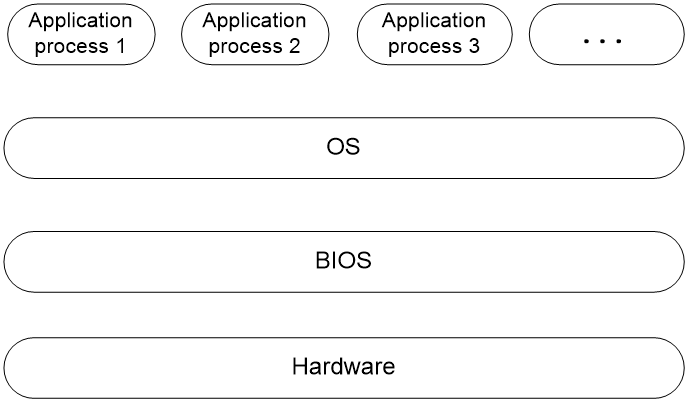
The Basic Input and Output System (BIOS) is a non-volatile firmware stored in the system ROM of a server. It is used to perform hardware initialization during server booting and provide runtime services for the operating systems. As shown in 图1-1, the BIOS interacts between the server hardware and the operating system (OS).
图1-1 Layered architecture of a server system
1.2 Applicable products
This document is applicable to the following products:
· H3C UniServer B5700 G5
· H3C UniServer R4300 G5
· H3C UniServer R4700 G5
· H3C UniServer R4900 G5
· H3C UniServer R4900LC G5
· H3C UniServer R5300 G5
· H3C UniServer R5500 G5 Intel
· H3C UniServer R6900 G5
1.3 Using this document
The information in this document is subject to change over time. You can access the H3C website to obtain the most recent version of the BIOS.
The information in this document might differ from your product if it contains custom configuration options or features.
The figures used in this document are for illustration only and might differ from your product.
2 Common BIOS tasks
This section provides procedures for the following common BIOS tasks:
· Entering the BIOS setup utility
· Displaying processor information
· Displaying memory information
· Displaying onboard drive information
· Configuring NVMe SSD RAID through VROC
· Configuring TXT (for the R4700/R4900/R6900 G5 server only)
· Setting HDM network information (except for the B5700 G5)
· Setting the system date and time
· Setting the server boot order
· Configuring serial port redirection
· Restoring BIOS default settings
2.1 Entering the BIOS setup utility
Connect a keyboard, a mouse, and a monitor to the server or enable the remote console from the HDM Web interface.
For information about enabling the remote console, see H3C Servers HDM User Guide.
Start or restart the server.
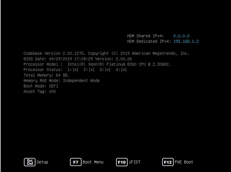
Press Del or Esc when the BIOS startup screen opens, as shown in 图2-1.
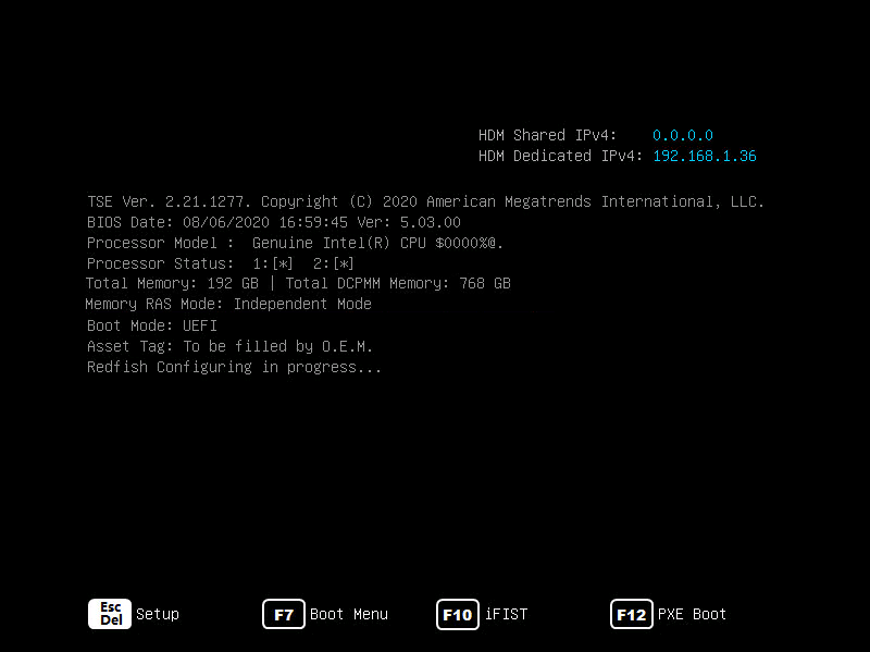
|
Key |
Description |
|
Esc/Del |
Enter the BIOS setup screen. |
|
F7 |
Enter the Boot menu. |
|
F10 |
Enter the iFIST GUI. For more information, see H3C Servers iFIST User Guide. |
|
F12 |
Enter PXE boot. |
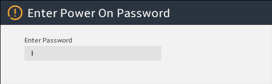
Enter the BIOS password if required during boot-up, as shown in 图2-2.
By default, no BIOS passwords are set. For information about BIOS password setup, see "Configuring BIOS passwords."
If you enter an incorrect password for three consecutive times, the server will restart automatically.
If you forget the password, use the system maintenance switch in the server to clear BIOS password settings. For more information about the system maintenance switch, see the user guide for the server.
|
|
IMPORTANT: If you use the system maintenance switch to clear BIOS passwords, restore the switch to the default position after you set new password settings. If you fail to do so, the new settings will be cleared. |
图2-2 Entering the power on password
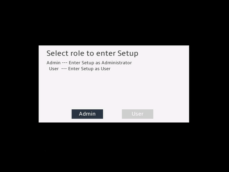
(Optional.) If you have set a BIOS administrator password and a user password, select the role before entering BIOS setup, as shown in 图2-3.
图2-3 Selecting a role to enter setup
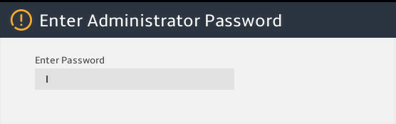
Enter the password of the selected role, as shown in 图2-4.
图2-4 Entering the BIOS password
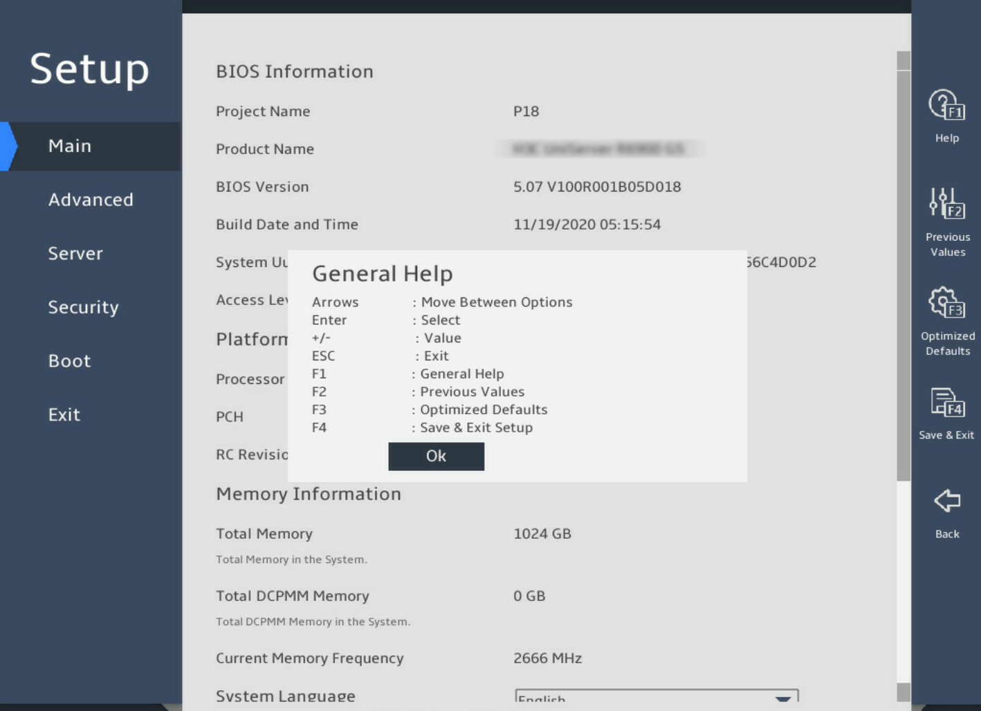
On the BIOS setup utility screen that opens, press F1, and then follow the instructions in the dialog box that opens to configure BIOS settings, as shown in 图2-5.
表2-9 shows detailed information about the operation keys.
图2-5 BIOS setup utility screen
|
Key |
Description |
|
Arrows |
Select a screen or item. |
|
Enter |
Select an item to edit its value or access a submenu. |
|
+/- |
Change the field value of the selected item. |
|
ESC |
Exit the BIOS setup utility or return to the previous screen. |
|
F1 |
Display the general help window. |
|
F2 |
Load previous values in the BIOS. |
|
F3 |
Load default values in the BIOS. |
|
F4 |
Save the current configuration and exit the BIOS. As a best practice, use the Save Changes And Reset option on the Exit screen. |
2.2 Setting the BIOS language
Enter the BIOS setup utility. For more information, see "Entering the BIOS setup utility."
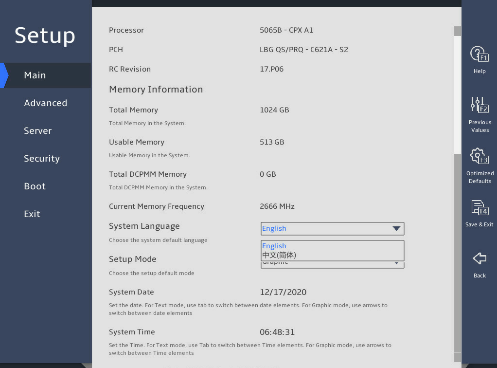
Select Main > Setup Mode, and press Enter, as shown in 图2-6.
Select a BIOS language mode from the System Language field. The setting takes effect immediately.
图2-6 Setting the BIOS language
2.3 Setting the BIOS setup mode
Enter the BIOS setup utility. For more information, see "Entering the BIOS setup utility."
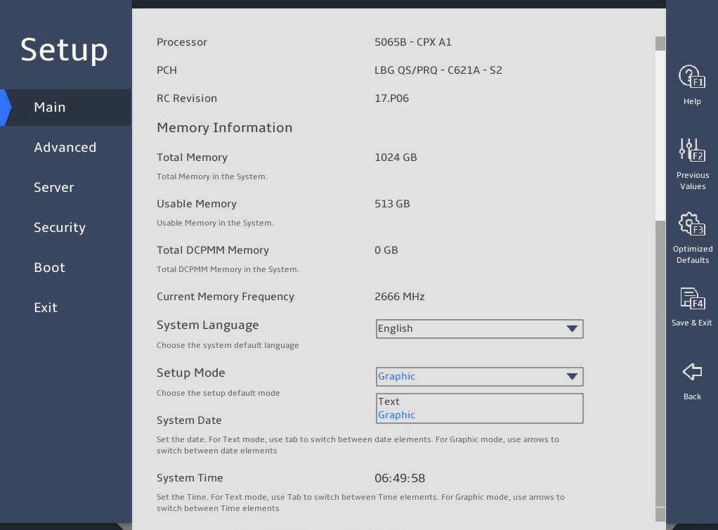
Select Main > Setup Mode, and press Enter, as shown in 图2-7.
Select a BIOS setup mode (Text or Graphic) from the Setup Mode field, and then press Enter.
图2-7 Setting the BIOS setup mode
Press F4 and then select Ok to save the configuration. The server will restart automatically.
2.4 Displaying processor information
Enter the BIOS setup utility. For more information, see "Entering the BIOS setup utility."
Select Advanced > Socket Configuration, and press Enter.
Select Processor Configuration, and press Enter.
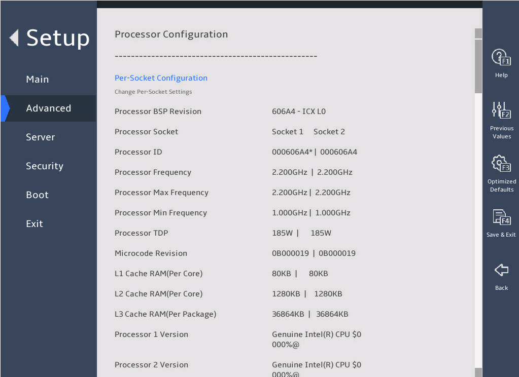
The Processor Configuration submenu that opens displays detailed information about processors, as shown in 图2-8.
For more information about the Processor Configuration submenu, see "Processor Configuration submenu."
图2-8 Processor Configuration submenu screen
2.5 Displaying memory information
Enter the BIOS setup utility. For more information, see "Entering the BIOS setup utility."
Select Advanced > Socket Configuration > Memory Configuration, and press Enter.
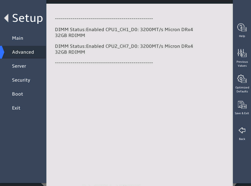
The Memory Configuration submenu that opens displays memory capacity and frequency information, as shown in 图2-9.
Select Memory Topology to enter Memory Topology submenu.
For more information about the Memory Configuration submenu, see "Memory Configuration submenu."
图2-9 Memory Configuration submenu
2.6 Displaying onboard drive information
1. About this task
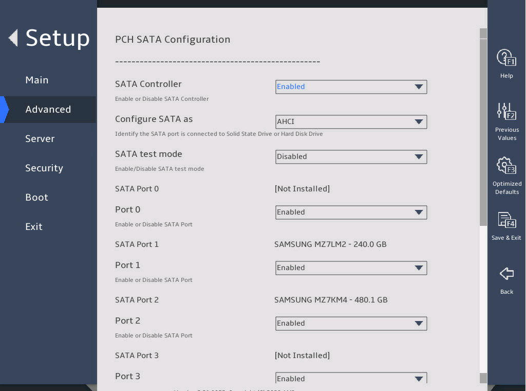
Both the PCH SATA Configuration and PCH sSATA Configuration submenus display onboard drive information. The following uses the PCH SATA Configuration submenu for example. For more information about the submenus, see "PCH Configuration submenu."
2. Procedure
Enter the BIOS setup utility. For more information, see "Entering the BIOS setup utility."
Select Advanced > Platform Configuration > PCH Configuration > PCH SATA Configuration, and press Enter.
The PCH SATA Configuration submenu that opens displays drive information, as shown in 图2-10.
图2-10 PCH SATA Configuration submenu
2.7 Configuring NVMe SSD RAID through VROC
1. About this task
On the Intel® Virtual RAID on CPU (Intel® VROC) menu of the BIOS Setup utility, you can configure virtual RAID of NVMe SSDs. This feature is available only when the Intel Volume Management Device (VMD) is enabled. By default, all VMD ports are disabled.
Make sure you have installed the Intel NVMe VROC module on the server.
· If you have installed the standard version of the VROC module, you can create RAID 0, RAID 1, and RAID 10.
· If you have installed the advanced version of the VROC module, you can create RAID 0, RAID 1, RAID 5, and RAID 10.
· If you have installed the Intel version of the VROC module, you can create RAID 0, RAID 1, RAID 5, and RAID 10 only for Intel NVMe SSDs.
2. Procedure
Enter the BIOS setup utility. For more information, see "Entering the BIOS setup utility."
Select Advance > Socket Configuration > IIO Configuration > Intel® VMD technology, as shown in 图2-11.
图2-11 Intel® VMD technology submenu screen

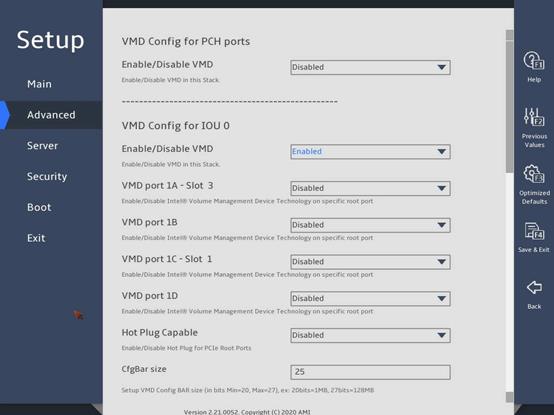
Identify the VMD config options based on the slot number of the NVMe drive, set the corresponding Enable/Disable VMD field to Enabled, and enable the VMD ports, as shown in 图2-12.
图2-12 VMD Config submenu screen
Press F4 to save the settings and restart the server.
Enter the BIOS setup utility. Select Advanced > Intel(R) virtual RAID on CPU, as shown in 图2-13.
图2-13 Intel® virtual RAID on CPU submenu screen
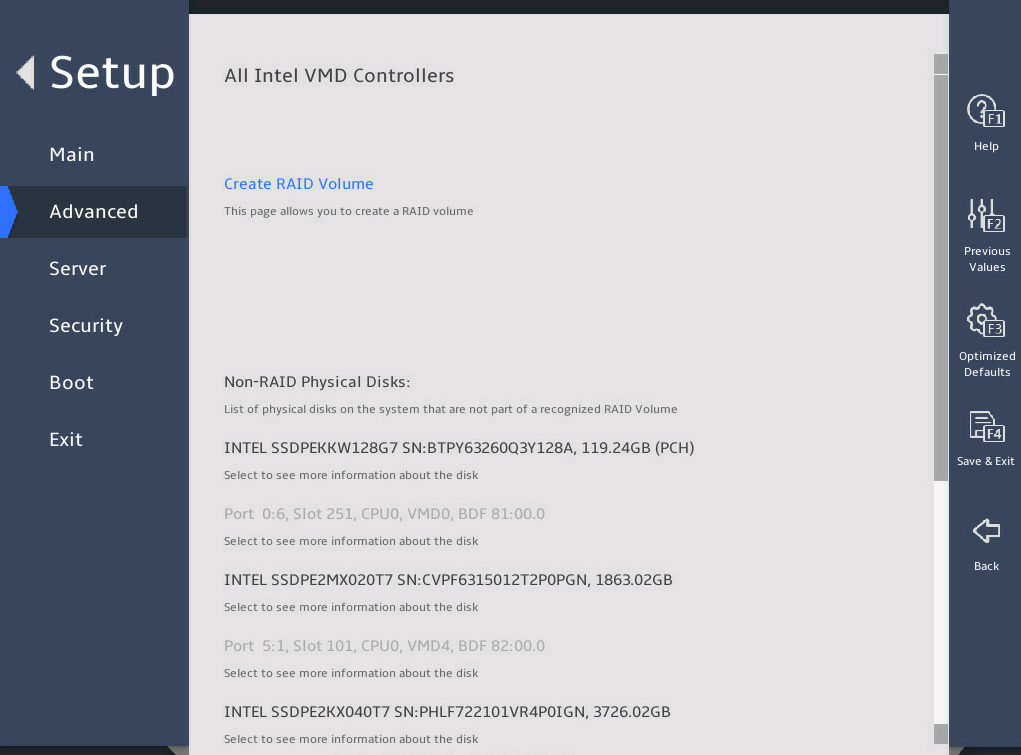
Select Create RAID Volume to enter the Create RAID Volume submenu.
Enter the RAID name and select the RAID level. If you want to create a RAID across VMD controllers, set Enable RAID spanned over VMD Controllers to X.
图2-14 Create RAID Volume submenu screen (1)

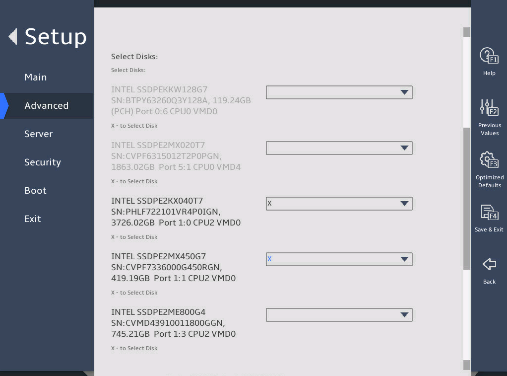
Select the disks to be added to the RAID array. X means the disk has been selected.
图2-15 Create RAID Volume submenu screen (2)
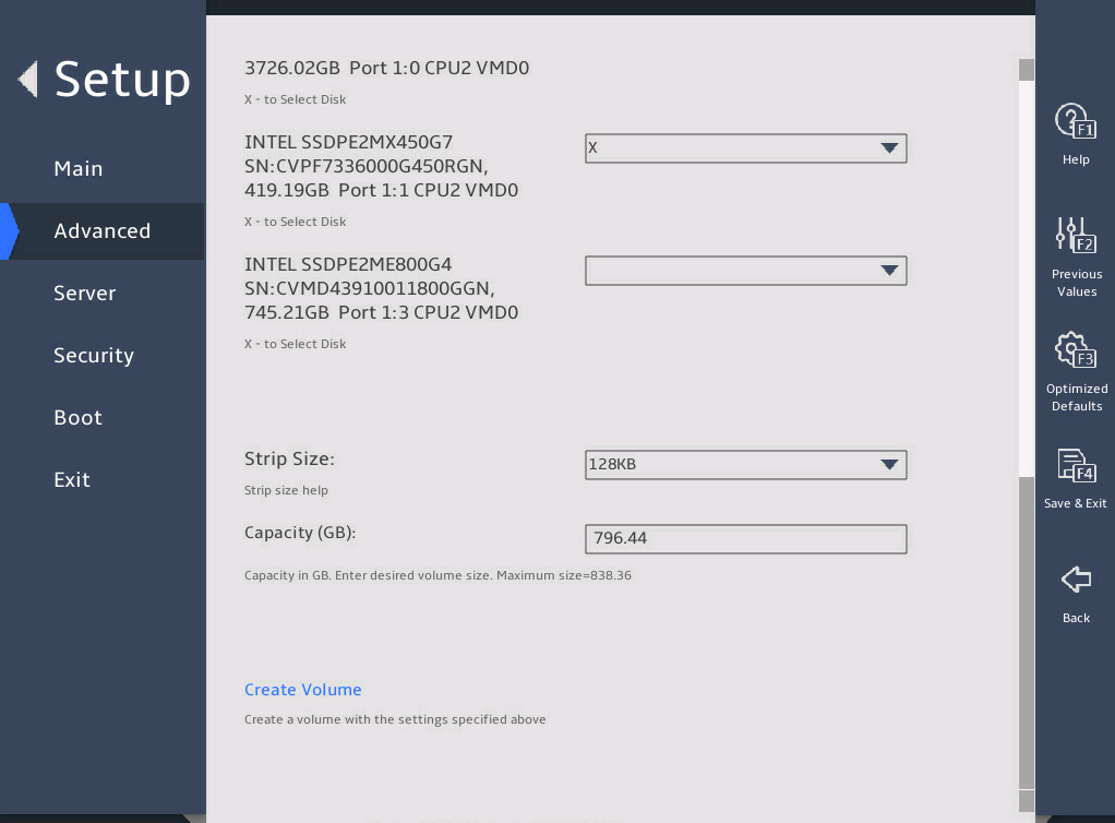
Set the strip size and capacity, and then select Create Volume.
图2-16 Create RAID Volume submenu screen (3)
Select Yes to complete RAID creation.
图2-17 Create RAID Volume submenu screen (4)

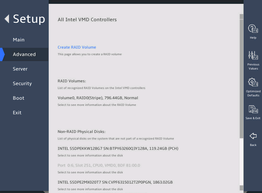
You can access the Intel® virtual RAID on CPU menu to view the created RAID array in the RAID Volumes field.
图2-18 Intel® virtual RAID on CPU submenu screen
2.8 Configuring PCIe ports
1. About this task
Perform this task to enable or disable PCIe ports (slots). With a PCIe port disabled, the operating system cannot identify the PCIe device connected to the port. To disable a PCIe device, you can perform this task to disable the corresponding port to avoid frequent PCIe device swapping.
2. Procedure
Enter the BIOS Setup untility. For more information, see"Entering the BIOS setup utility".
Select Advanced > Socket Configuration, and then press Enter.
图2-19 Socket Configuration submenu screen

In the Socket configuration submenu, select IIO Configuration, and then press Enter.
图2-20 IIO Configuration submenu screen
In the IIO Configuration submenu, select a processor configuration item, and then press Enter.
图2-21 Socket1 Configuration submenu screen

Select a port, and then press Enter.
For more information about the connected device for a port, access the HDM Web interface.
图2-22 Slot 3 – Port 1A configuration submenu screen

Select Enabled, Disabled, or Auto from the PCI-E Port field, and then press Enter.
Press F4 and then select Ok to save the configuration and exit the BIOS utility.
The configuration takes effect after the server reboots.
2.9 Configuring PXE for NICs
1. About this task
This feature configures the NIC preboot execute environment (PXE) feature to boot the server through the network.
Most server NICs have been installed with the PXE feature. When PXE is enabled, the server can download a startup image from a remote device through the network for OS startup or installation.
2. Restrictions and guidelines
If the UEFI mode is used, configure an image file that supports the UEFI mode in PXE server configuration.
3. Procedure
Enter the BIOS setup utility. For more information, see "Entering the BIOS setup utility."
Select Advance > Network Configuration, and press Enter, as shown in 图2-23.
图2-23 Network Configuration submenu screen
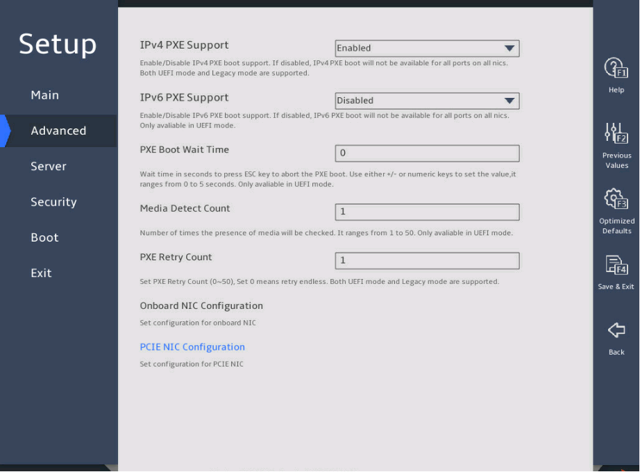
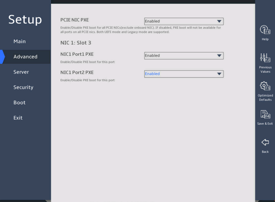
In the PCIE NIC Configuration submenu, configure the PXE feature for all ports or a single port, as shown in 图2-24.
¡ To configure PEX for all ports, set PCIE NIC PXE.
¡ To configure PEX for a single port, set NIC Port PXE for the specific port.
图2-24 PCIE NIC Configuration submenu screen
2.10 Configuring TXT (for the R4700/R4900/R6900 G5 server only)
1. About this task
Trusted Execution Technology (TXT) is a security feature supported by Intel processors for comprehensive data security in virtual computing. Intel TXT is available when TPM 2.0 or TPM 1.2 is used.
2. Prerequisites
Enable the following features:
· All Intel processor cores.
· Hyper-Threading [ALL].
· Intel® VT for Directed I/O (VT-d).
· TPM (physical TPMs are enabled by default).
3. Procedure
Enter the BIOS Setup utility. For more information, see "Entering the BIOS setup utility".
Select Advanced > Processor Configuration, and then press Enter.
图2-25 Enable Intel(R) TXT item
Select Enabled or Disabled from the Enable Intel(R) TXT field, and then press Enter.
Press F4 and then select Ok to save the configuration and exit the BIOS utility.
The configuration takes effect after the server reboots.
2.11 Setting HDM network information (except for the B5700 G5)
1. About this task
Perform this task to configure IP address settings of HDM network ports and the method for obtaining the network information.
The submenus are the same for both HDM dedicated and shared network ports. The following uses the HDM shared network port for example.
2. Restrictions and guidelines
Do not disconnect the AC power immediately after you modify and save HDM IPv4 and IPv6 address settings. Otherwise, the IP address setting might fail.
To avoid network storms, make sure the IP address of the HDM shared network port is on a network segment different than the HDM dedicated network port.
To avoid device disconnection, make sure HDM network configurations are correct.
3. Procedure
Enter the BIOS setup utility. For more information, see "Entering the BIOS setup utility."
Select Server > HDM Network Configuration, and press Enter.
As shown in 图2-26, in the HDM Network Configuration submenu, both IPv4 configuration and IPv6 configuration are supported. Take IPv4 network configuration as an example.
Select IPv4 Network Configuration.
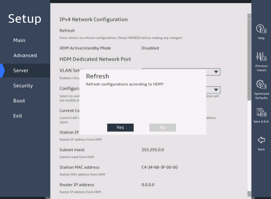
Select Refresh, press Enter, and then select Yes to refresh HDM network configuration.
图2-26 HDM Network Configuration submenu
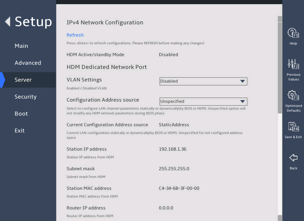
Select Configuration Address source for the HDM shared network port, and press Enter.
图2-27 HDM Network Configuration submenu
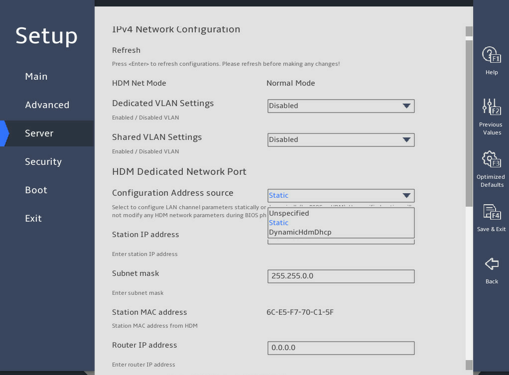
From the Configuration Address source field, select the method for obtaining HDM network information. Options are:
¡ Unspecified—Retains current configuration.
¡ Static—Uses manually specified configuration.
¡ DynamicHdmDhcp—Uses network information obtained through DHCP.
图2-28 HDM Network Configuration submenu
Press Enter. If you select Static as the method for obtaining HDM network information, edit the following items and press Enter every time you finish editing:
¡ Station IP address—Enter a static IP address. This item is required.
¡ Subnet mask—Enter a subnet mask for the static IP address. This item is required.
¡ Router IP address—Enter a gateway IP address.
Press F4 and then select Ok to save the configuration.
The server will restart automatically.
2.12 Configuring BIOS passwords
2.12.1 About this task
BIOS passwords include a boot password as well as an administrator password and a user password for BIOS Setup. By default, no passwords are set.
· A boot password is required each time the server starts up.
· An administrator password or a user password is required each time you enter the BIOS Setup screen.
If only the administrator password is set, you can enter this password to obtain administrator privileges. The system prompts for the password when you use shortcut keys to enter the BIOS setup utility, iFIST, boot menu, or PXE boot interface.
If only the user password is set, you can enter this password to obtain user privileges. 表2-57 shows the menu items that are accessible in the BIOS with the user privileges.
表2-3 BIOS menu items accessible with the user password
|
Level-1 menu |
Submenu items |
|
Security |
User Password |
|
Exit |
Save Changes and Exit |
|
Discard Changes and Exit |
|
|
Save Changes and Reset |
|
|
Discard Changes and Reset |
|
|
Save Changes |
|
|
Discard Changes |
2.12.2 Restrictions and guidelines
When you change a BIOS password, make sure the new password is different from the most recent three passwords.
The BIOS passwords must meet the following requirements:
· A case-sensitive string of 8 to 20 characters. Valid characters are letters, digits, spaces, and special characters in 表2-58.
· Contain a minimum of two character types from uppercase letters, lowercase letters, and digits.
· Contain a minimum of one space or special character.
|
Character name |
Symbol |
Character name |
Symbol |
|
Back quote |
` |
Tilde |
~ |
|
Exclamation point |
! |
At sign |
@ |
|
Pound sign |
# |
Dollar sign |
$ |
|
Percent sign |
% |
Caret |
^ |
|
Ampersand sign |
& |
Asterisk |
* |
|
Left parenthesis |
( |
Right parenthesis |
) |
|
Underscore |
_ |
Plus sign |
+ |
|
Minus sign |
- |
Equal sign |
= |
|
Left bracket |
[ |
Right bracket |
] |
|
Back slash |
\ |
Left brace |
{ |
|
Right brace |
} |
Vertical bar |
| |
|
Semi-colon |
; |
Apostrophe |
' |
|
Colon |
: |
Quotation marks |
" |
|
Comma |
, |
Dot |
. |
|
Forward slash |
/ |
Left angle bracket |
< |
|
Right angle bracket |
> |
Question mark |
? |
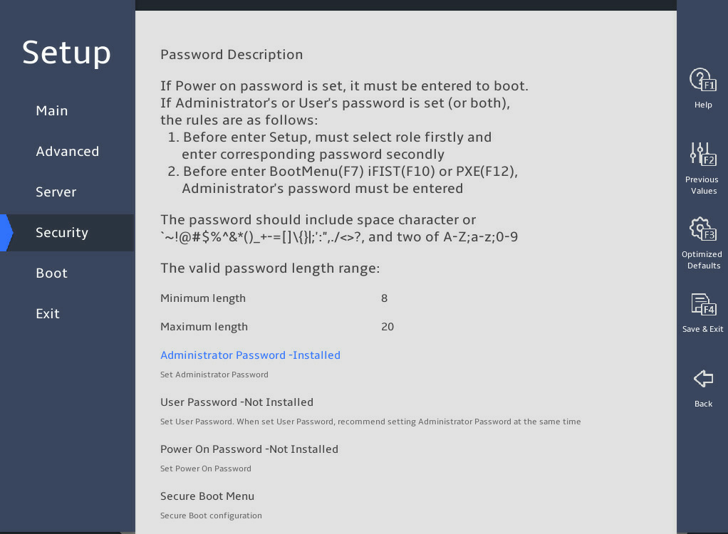
2.12.3 Setting a BIOS password
The procedure is the same for setting the administrator password and the user password. This section uses the administrator password as an example.
To set the administrator password:
Enter the BIOS setup utility. For more information, see "Entering the BIOS setup utility."
Select Security > Administrator Password -Not Installed, and press Enter, as shown in 图2-29.
图2-29 Setting the administrator password

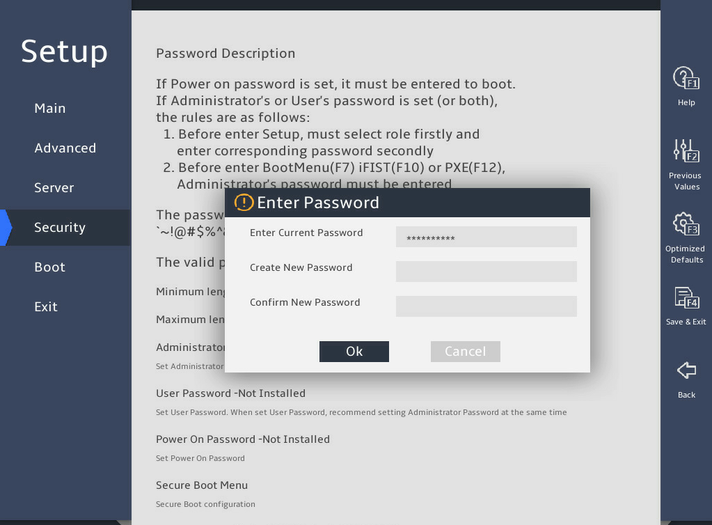
In the Enter Password dialog box that opens, enter an administrator password, confirm the password, select Ok, and then press Enter, as shown in 图2-30.
图2-30 Creating the administrator password
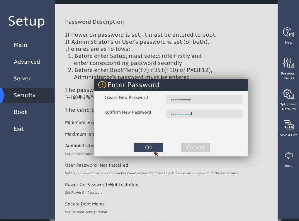
表2-5 Press F4 and then select Ok to save the configuration.
The server will restart automatically.
2.12.4 Deleting a BIOS password
The procedure is the same for deleting the administrator password and the user password. This section uses the administrator password as an example.
To delete the administrator password:
表2-6 Enter the BIOS setup utility. For more information, see "Entering the BIOS setup utility."
表2-7 Select Security > Administrator Password -Installed, and press Enter, as shown in 图2-31.
图2-31 Selecting the administrator password
In the Enter Password dialog box that opens, enter the current administrator password, leave the new password fields empty, select Ok, and then press Enter, as shown in 图2-32.
图2-32 Entering the current administrator password
In the WARNING dialog box that opens, select Ok, and press Enter, as shown in 图2-33.
图2-33 Confirming the deletion
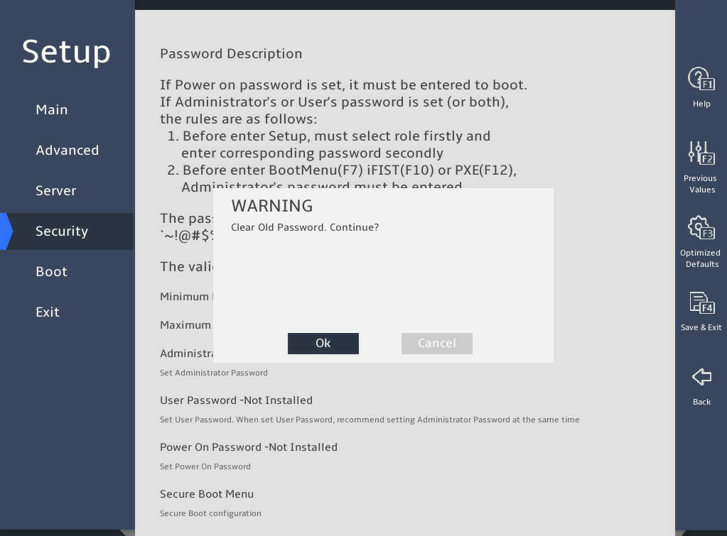
表2-8 Press F4 and then select OK to save the configuration.
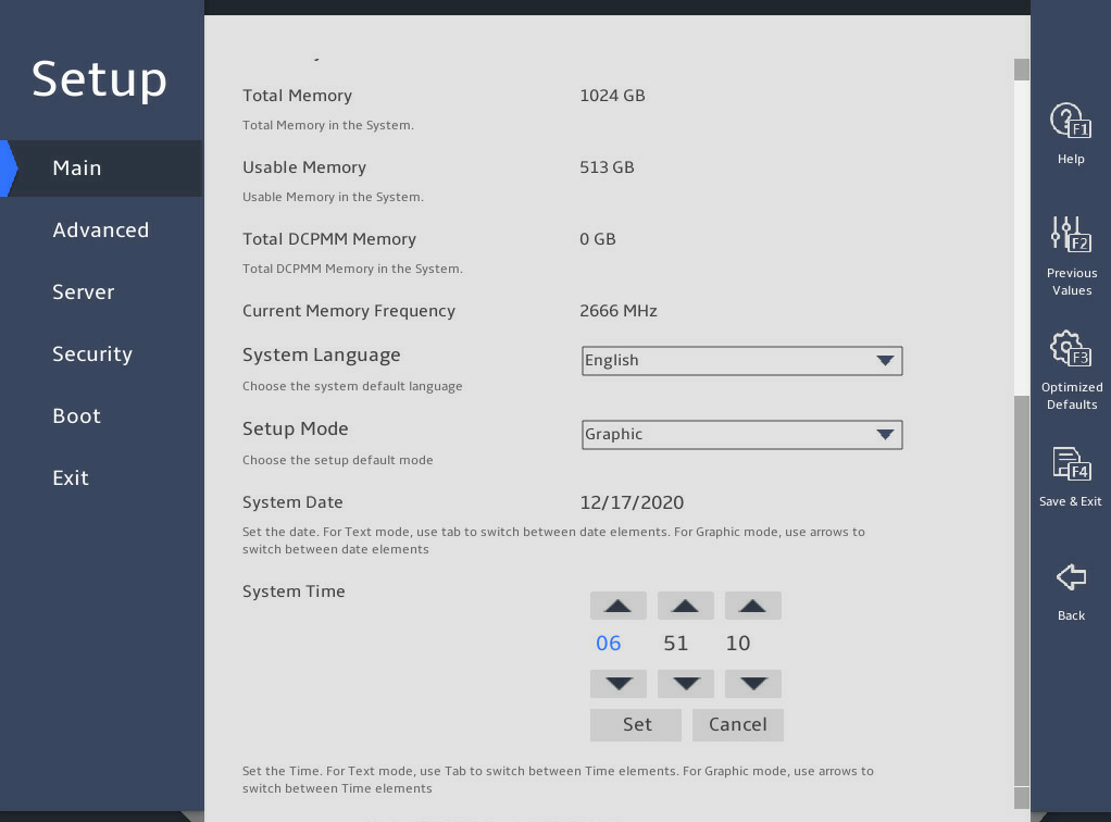
2.13 Setting the system date and time
表2-9 Enter the BIOS setup utility. For more information, see "Entering the BIOS setup utility."
表2-10 Select the Main menu.
表2-11 Set the system date, as shown in 图2-34:
a. Select System Date.
The system date is in the format of mm/dd/yyyy.
b. Press → or ← to switch between the month, day, and year fields and then use the following methods to modify the value:
- Press + or ↑ to increase the value by 1.
- Press – or ↓ to decrease the value by 1.
c. To save the configuration, press → or ← to select the Set button, and then press Enter.
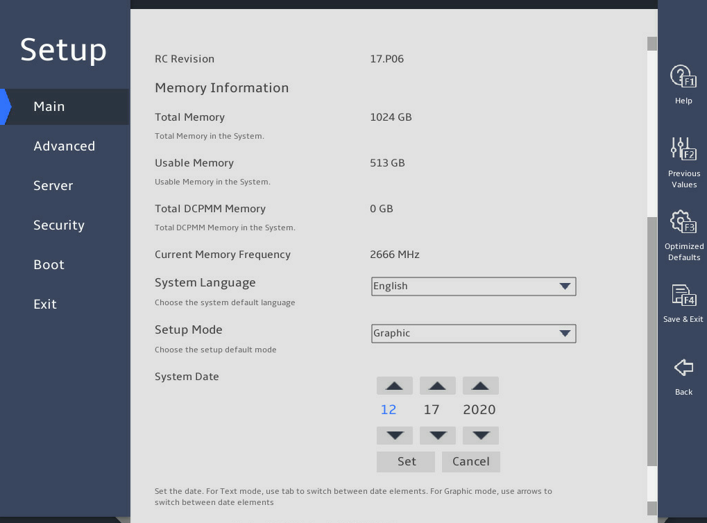
表2-12 Set the system time, as shown in 图2-35:
a. Select System Time.
The system time uses the 24-hour time system and is in the format of hh:mm:ss.
b. Press → or ← to switch between the hour, minute, and second fields and then use the following methods to modify the value:
- Press + or ↑ to increase the value by 1.
- Press – or ↓ to decrease the value by 1.
c. To save the configuration, press → or ← to select the Set button, and then press Enter.
2.14 Setting the BIOS boot mode
1. About this task
The server supports two BIOS boot modes: legacy mode and UEFI mode.
By default, the boot mode is UEFI. For operating systems that support only the legacy mode, change the boot mode to legacy.
2. Restrictions and guidelines
An operating system can run only in the BIOS boot mode under which the system was installed. For example, operating systems installed in legacy mode cannot start up in UEFI mode, and operating systems installed in UEFI mode cannot start up in legacy mode.
3. Procedure
Enter the BIOS setup screen. For more information, see "Entering the BIOS setup utility."
As shown in 图2-36, select Boot > Boot mode select, and press Enter.
From the Boot mode select field, select LEGACY or UEFI, and press Enter.
图2-36 Setting the BIOS boot mode
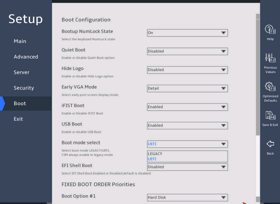
表2-13 Press F4 and then select Ok to save the configuration.
The server will restart automatically.
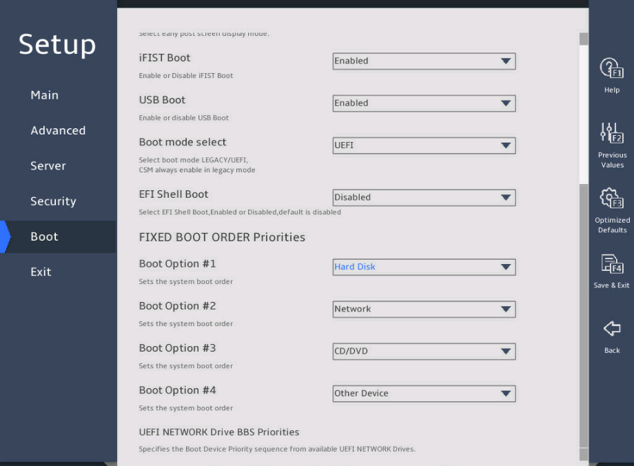
2.15 Setting the server boot order
1. About this task
Perform this task to change the server boot order.
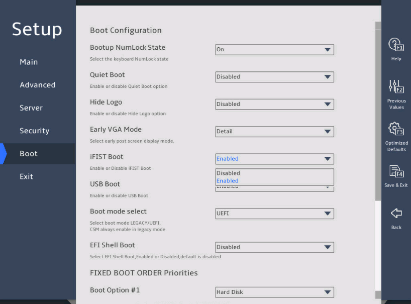
The default boot order is hard disk > network > CD/DVD > other device as shown in the Fixed Boot Order Priorities list in 图2-37.
2. Restrictions and guidelines
If the server has more than one boot devices of the same type, the Fixed Boot Order Priorities list displays only the first boot device. To change the first boot device, enter the corresponding priorities submenu of the boot device, and then set the first boot option. For example, to change the first boot option for hard disks, enter the UEFI Hard Disk Drive BBS Priorities submenu as shown in 图3-149, and then set the first boot option.
3. Procedure
Enter the BIOS setup utility. For more information, see "Entering the BIOS setup utility."
As shown in 图2-37, select the Boot menu.
图2-37 Boot menu
|
Item |
Example |
|
Hard Disk |
Disk (including virtual drives), SD cards, and USB-HDD. |
|
Network |
Network. |
|
CD/DVD |
CD-ROM and DVD-ROM (including virtual ones), USB-CD, and USB-DVD. |
|
Other Device |
The options include but are not limited to: · Boot option for entering the Shell command line interface. This option is available only when EFI Shell Boot is set to Enabled. · Other unidentified boot devices. |
|
Disabled |
The boot option is disabled. |
表2-14 As shown in 图2-38, select the option to be modified from the Fixed Boot Order Priorities area, and press Enter.
表2-15 In the dialog box that opens, select a new boot device type, and press Enter.
图2-38 Changing a boot option submenu screen
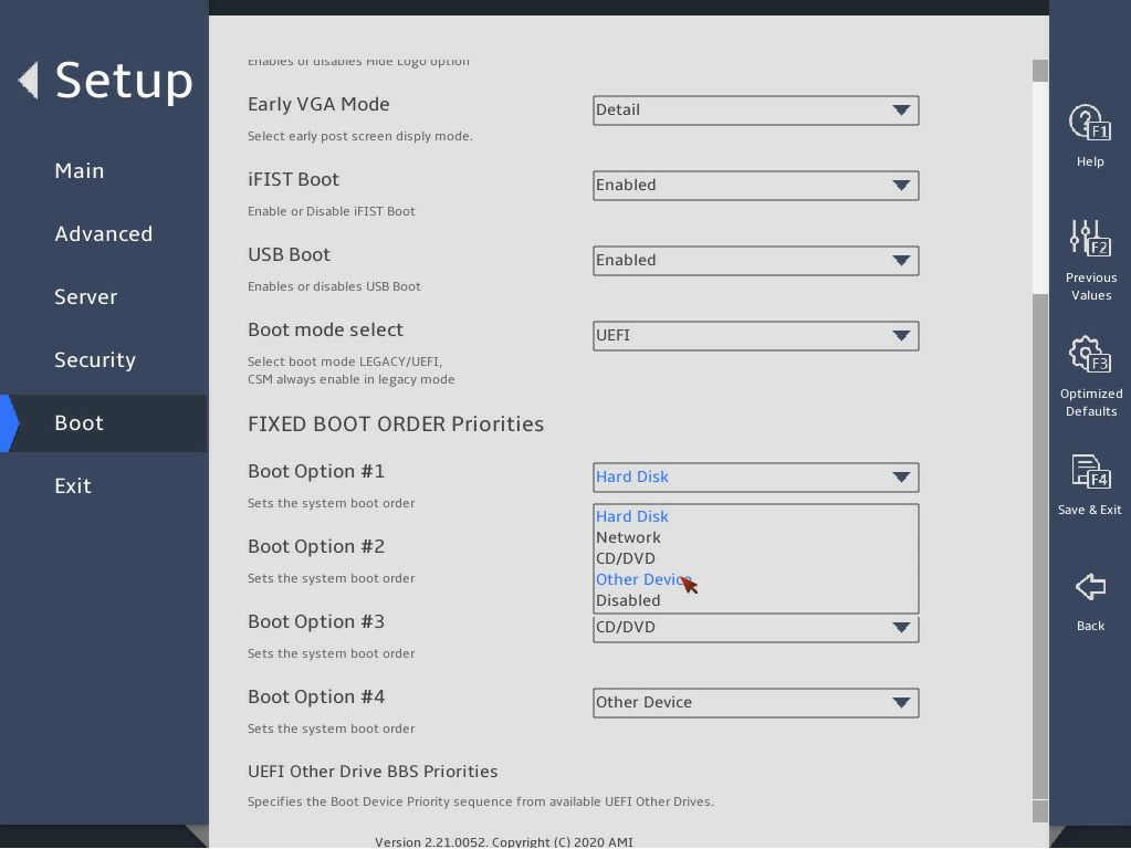
Press F4 and then select Ok to save the configuration and exit the menu. The configuration takes effect immediately.
2.16 Enabling or disabling iFIST
1. About this task
This feature enables or disables iFIST. The integrated Fast Intelligent Scalable Toolkit (iFIST) is a standalone intelligent deployment tool embedded in the server. Users do not need to install it. For more information about the iFIST, see H3C Servers iFIST User Guide.
If iFIST is enabled, after the server is initialized, you can enter the iFIST system from the BIOS. If iFIST is disabled, the iFIST Boot shortcut will not be displayed on the BIOS set utility, and you cannot start iFIST by pressing F10.
2. Procedure
Enter the BIOS setup utility. For more information, see "Entering the BIOS setup utility."
Select Boot > iFIST Boot, select Enabled or Disabled, and then press Enter, as shown in 图2-39.
图2-39 iFIST boot option
Press F4 and then select Ok to save the configuration and exit the BIOS utility.
The configuration takes effect after the server reboots.
2.17 Logging in to iFIST
Press F10 on the BIOS boot screen to access the iFIST GUI. iFIST login screen opens after iFIST starts up.
If the boot screen does not display the iFIST shortcut, make sure iFIST is enabled. For more information, see "Enabling or disabling iFIST."
图2-40 BIOS boot screen
2.18 Configuring serial port redirection
1. About this task
Serial port redirection redirects console information to the specified serial port. You can perform this task to enable or disable this feature.
2. Procedure
Enter the BIOS setup utility. For more information, see "Entering the BIOS setup utility."
Select Advanced > Serial Port Console Redirection, and then press Enter.
图2-41 Serial Port Console Redirection subscreen
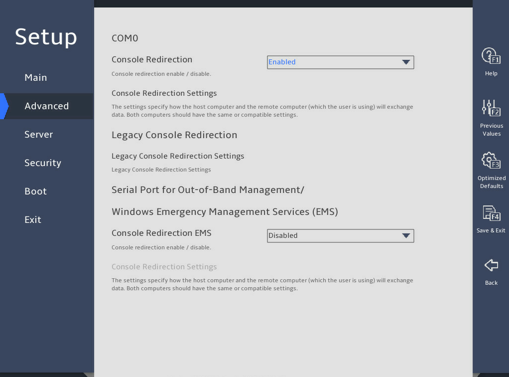
Select Enabled or Disabled from the Console Redirection field, and then press Enter.
If you enabled this feature, select Console Redirection Settings, press Enter, and configure redirection parameters as needed.
Press F4 and then select Ok to save the configuration and exit the BIOS utility.
The configuration takes effect after the server reboots.
2.19 Restoring BIOS default settings
1. About this task
You can perform this task to restore BIOS to its default settings if unknown modifications to the BIOS cause system problems.
2. Procedure
Enter the BIOS setup utility. For more information, see "Entering the BIOS setup utility."
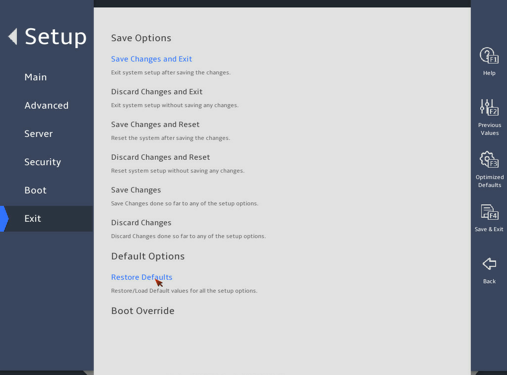
Press F3 in the BIOS, or select Exit > Restore Defaults and press Enter as shown in 图2-42.
Press F4 and Enter to save the settings. The configuration will take effect after the server reboots.
图2-42 Restoring the default from the Exit submenu screen
3 BIOS menus
3.1 Main menu
As shown in 图3-1 and 图3-2, the Main menu contains information about the BIOS, memory, system language, and system time and date. For more information about the menu items, see 表3-1.
图3-1 Main menu screen (1)
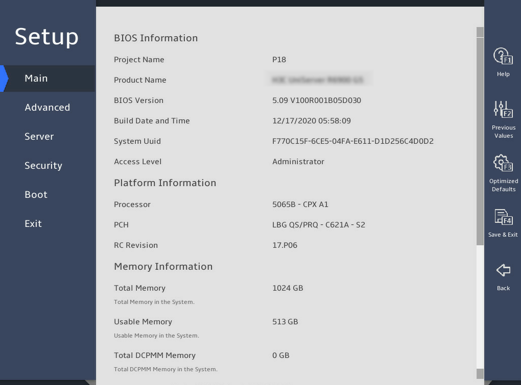
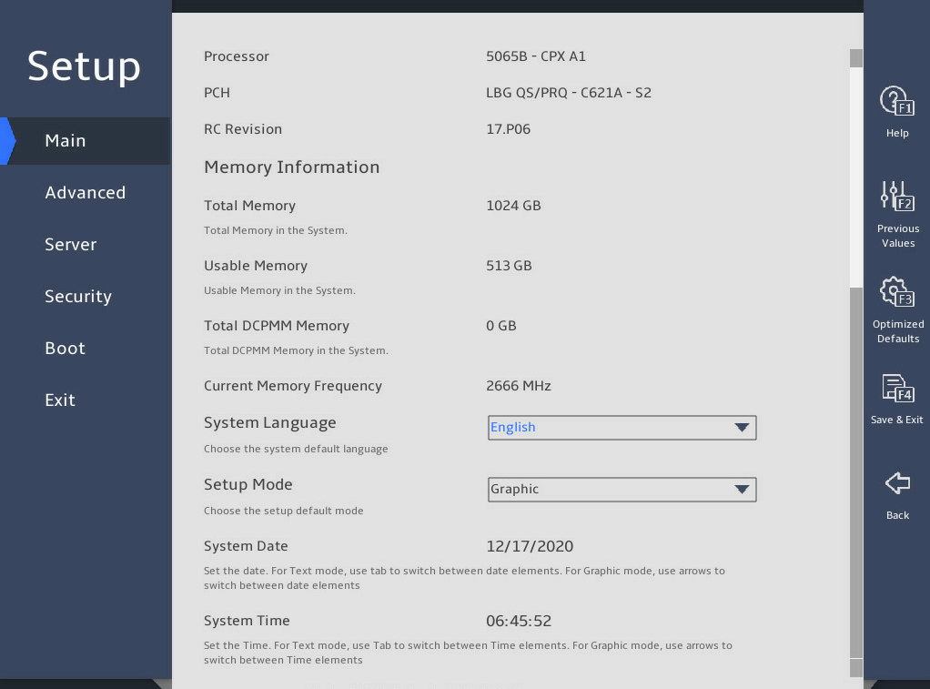
表3-1 Items on the Main menu screen
|
Item |
Description |
Default |
|
BIOS Information |
||
|
Project Name |
Displays the project name. |
N/A |
|
Product Name |
Displays the product name. |
N/A |
|
BIOS Version |
Displays the BIOS version. |
N/A |
|
Build Date and Time |
Displays the compiling date and time of the BIOS build. |
N/A |
|
System Uuid |
Displays the universally unique identifier (UUID) of the system. |
N/A |
|
Access Level |
Displays the privileges of the current login role. |
N/A |
|
Platform Information |
||
|
Processor |
Displays the CPU ID and stepping. |
N/A |
|
PCH |
Displays the platform controller hub (PCH) model. |
N/A |
|
RC Revision |
Displays the RC version. |
N/A |
|
Memory Information |
||
|
Total Memory |
Displays the total memory capacity of DRAM in GB. |
N/A |
|
Usable Memory |
Displays the usable DRAM memory capacity, in GB. When a specific memory mode, such as memory mirroring, is set, the total memory capacity is different from the actual usable memory capacity. This item displays the actual usable memory capacity. |
N/A |
|
Total DCPMM Memory |
Displays the total memory capacity of DCPMM in GB. DCPMM should be used together with DRAM. For information about how to install DCPMM, see the user guide. |
N/A |
|
Current Memory Frequency |
Displays the current memory frequency. For information about setting the memory frequency, see "Memory Configuration submenu." |
N/A |
|
System Language |
Displays the language used in the system. The BIOS supports English and simplified Chinese. To switch between the languages, press Enter. |
English |
|
Setup Mode |
Set the BIOS setup mode. Options: · Text. · Graphic. |
Graphic |
|
System Date |
Displays the system date. You can change the system date as needed. The system date is in the format of mm/dd/yyyy. To move between the month, day, and year fields, press Enter or Tab. To change the value for the selected field, use the following method: · Press + to increase the value by 1. · Press - to decrease the value by 1. |
N/A |
|
System Time |
Displays the system time. You can change the system time as needed. The system time is in the format of hh:mm:ss in 24-hour format. To move between the hour, minute, and second fields, press Enter or Tab. To change the value for the selected field, use the following method: · Press + to increase the value by 1. · Press - to decrease the value by 1. |
N/A |
3.2 Advanced menu
As shown in 图3-3 and 图3-4, the Advanced menu contains advanced system features and functionalities, which are described in 表3-2.
图3-3 Advanced menu screen (1)
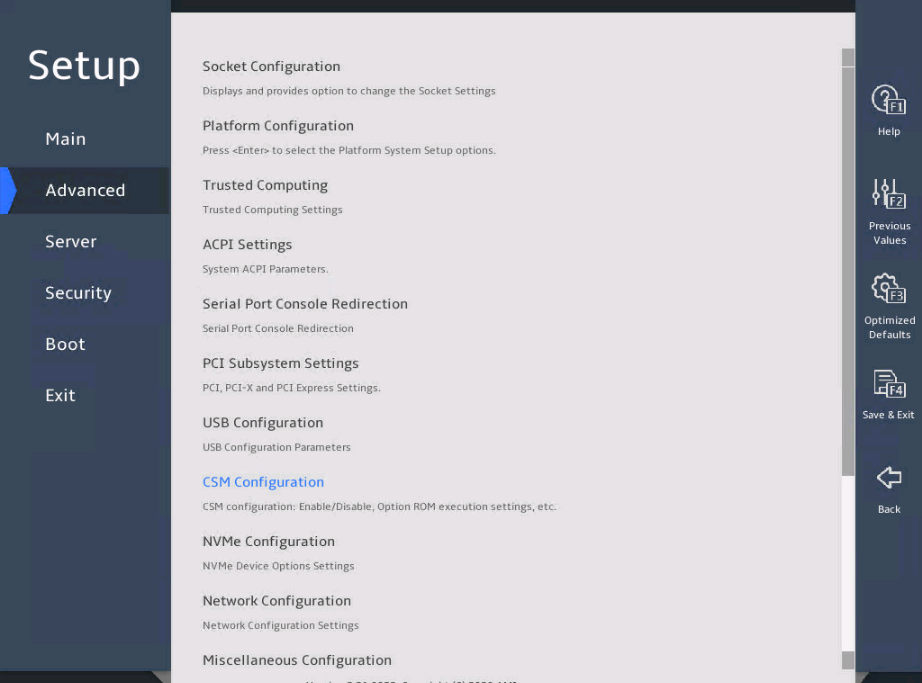
图3-4 Advanced menu screen (2)
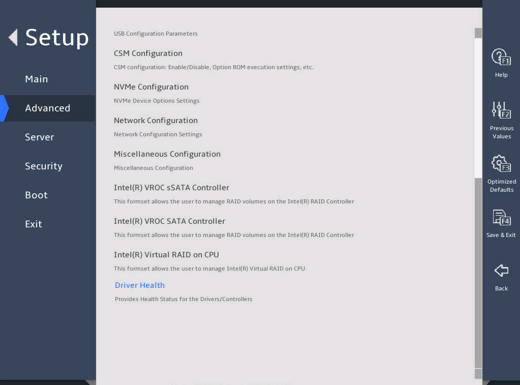
表3-2 Items on the Advanced menu screen
|
Item |
Description |
|
Socket Configuration |
Submenu for configuring the socket. |
|
Platform Configuration |
Submenu for configuring the platform. |
|
Trusted Computing |
Submenu for configuring trusted computing. |
|
ACPI Settings |
Submenu for configuring advanced configuration and power interface (ACPI) settings. |
|
Serial Port Console Redirection |
Submenu for configuring serial port console redirection. |
|
PCI Subsystem Settings |
Submenu for configuring the PCI subsystem. |
|
USB Configuration |
Submenu for configuring USB. |
|
CSM Configuration |
Submenu for configuring the compatibility support module (CSM). |
|
NVMe Configuration |
Submenu for configuring NVMe. |
|
Network Configuration |
Submenu for configuring network stacks. |
|
Miscellaneous Configuration |
Other configuration. |
|
iSCSI Configuration |
Submenu for configuring iSCSI. This submenu is available only for the B5700, R5300, and R5500 G5. |
|
Intel(R) VROC sSATA Controller |
Submenu for configuring Intel(R) VROC sSATA controller. This submenu is available only when the sSATA mode is set to RAID in the PCH settings. |
|
Intel(R) VROC SATA Controller |
Submenu for configuring Intel(R) VROC SATA controller. This submenu is available only when the SATA mode is set to RAID in the PCH settings. |
|
Intel(R) Virtual RAID on CPU |
Submenu for configuring Intel(R) Virtual RAID on CPU (Intel VROC). This submenu is available only when VMD is enabled. |
|
Driver Health |
Submenu for viewing the health state of drivers or controllers. This submenu is available only in UEFI boot mode. |
Socket Configuration submenu
图3-5 shows the Socket Configuration menu screen, on which you can configure processors, command reference code, uncore, memory, IIO, and advanced power management settings as described in 表3-3.
图3-5 Socket Configuration submenu screen
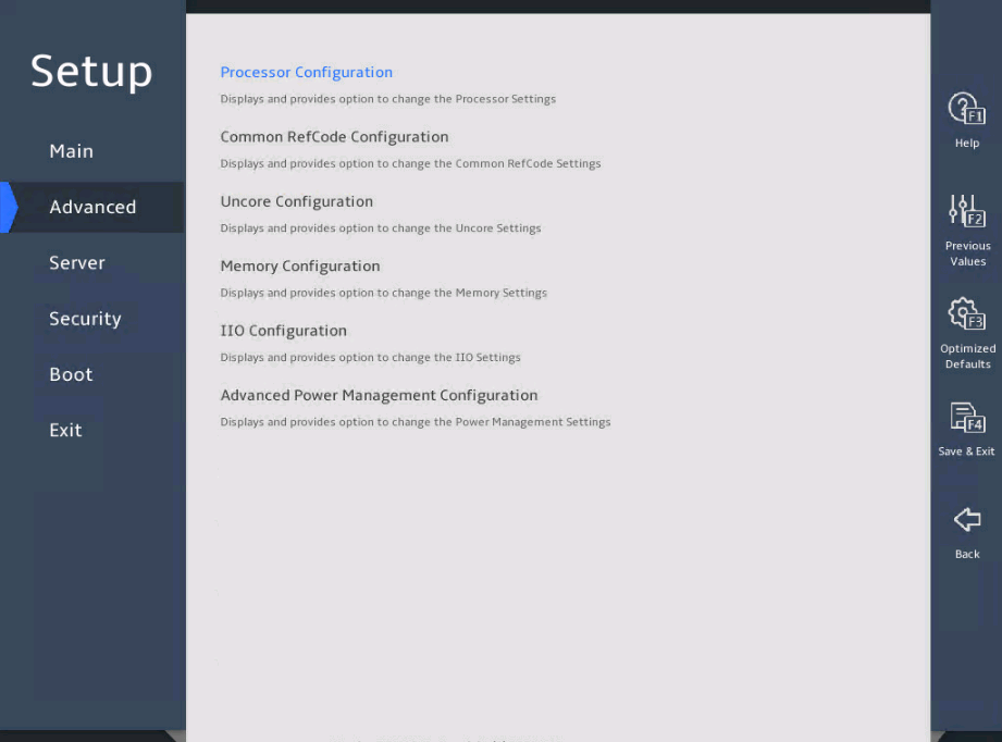
表3-3 Items on the Socket Configuration submenu screen
|
Item |
Description |
|
Processor Configuration |
Submenu for configuring processors, as shown in 图3-6, 图3-7, and 图3-8. The submenu items are described in 表3-4. |
|
Common RefCode Configuration |
Submenu for configuring the common reference code, as shown in 图3-13. The submenu items are described in 表3-7. |
|
Uncore Configuration |
Submenu for configuring Uncore parameters, as shown in 图3-14. The submenu items are described in 表3-8. |
|
Memory Configuration |
Submenu for configuring memory parameters, as shown in 图3-17 and 图3-18. The submenu items are described in 表3-11. |
|
IIO Configuration |
Submenu for configuring Integrated I/O module (IIO) parameters, as shown in 图3-26. The submenu items are described in 表3-17. |
|
Advanced Power Management Configuration |
Submenu for configuring advanced power management parameters, as shown in 图3-34. The submenu items are described in 表3-24. |
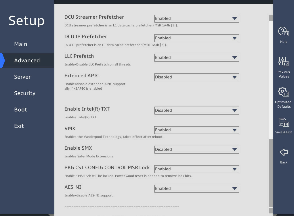
2. Processor Configuration submenu
图3-6, 图3-7, and 图3-8 show the Processor Configuration submenu screen, on which you can configure features such as hyper-threading and hardware prefetcher for processors.
The submenu items are described in 表3-4.
图3-6 Processor Configuration submenu screen (1)
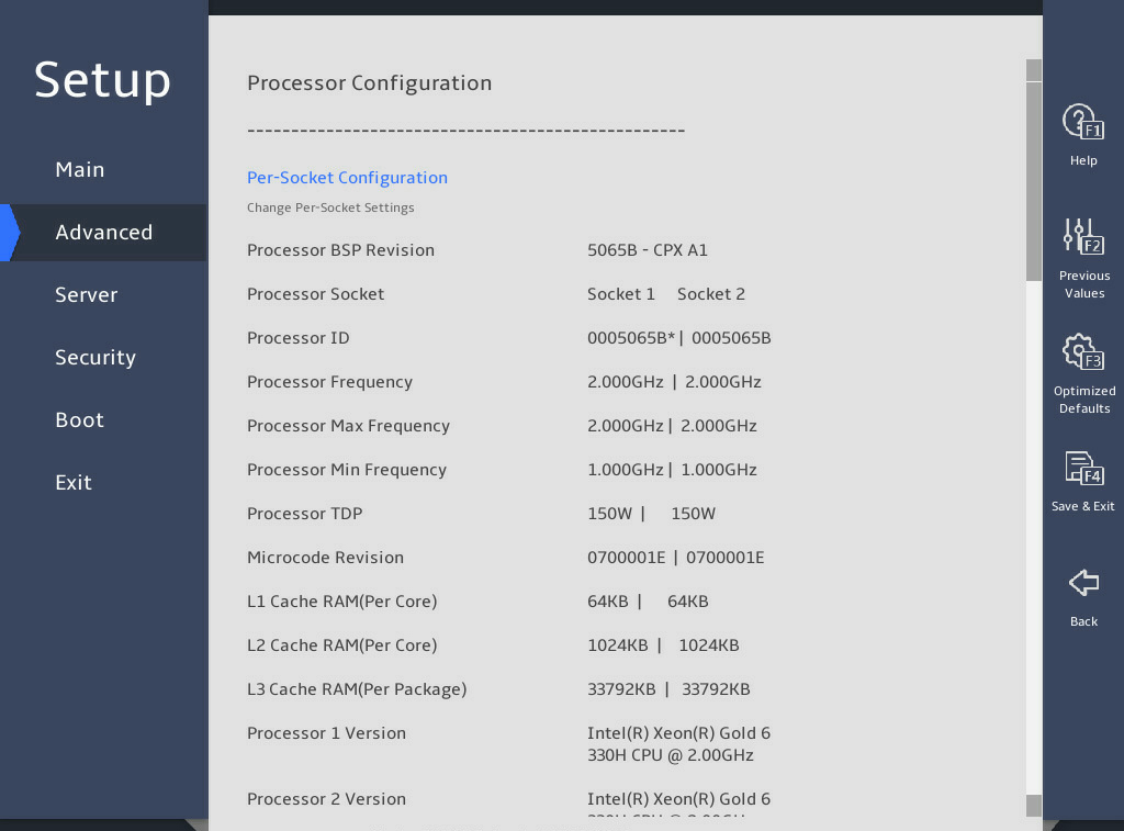
图3-7 Processor Configuration submenu screen (2)
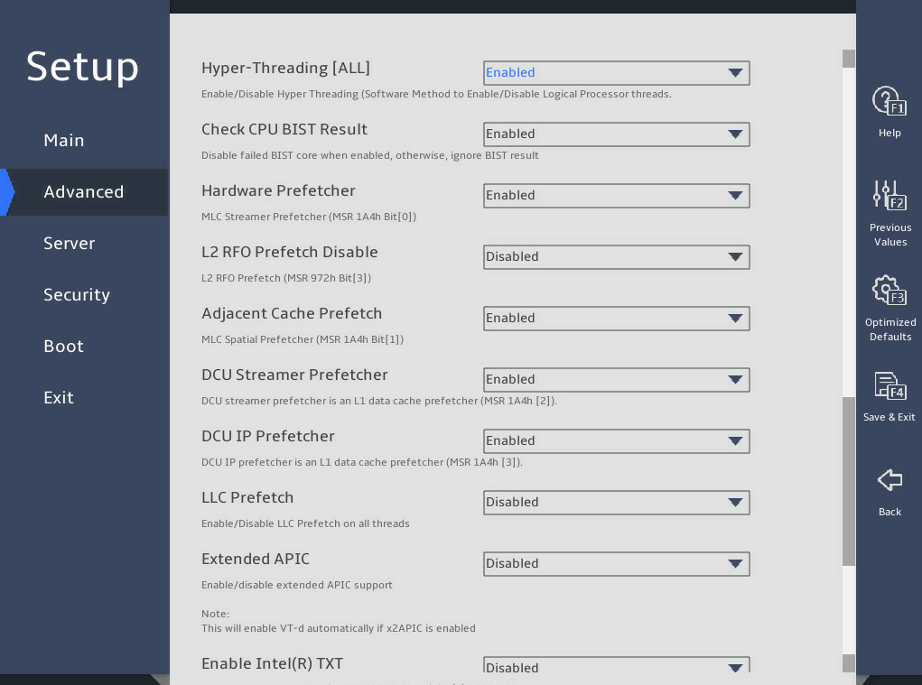
图3-8 Processor Configuration submenu screen (3)

图3-9 Processor Configuration submenu screen (4)

图3-10 Processor Configuration submenu screen (5)
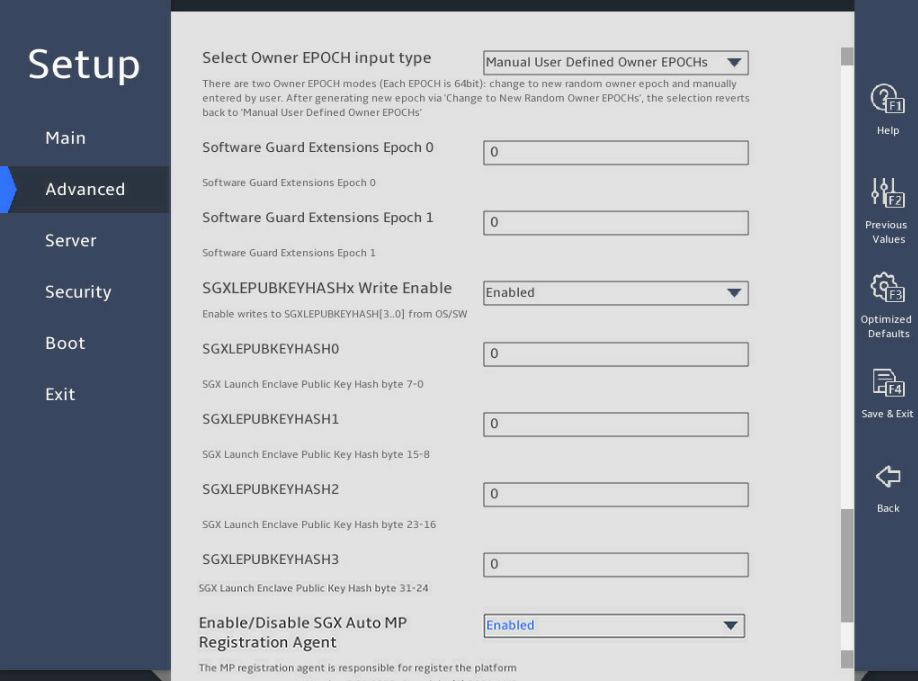
表3-4 Items on the Processor Configuration submenu screen
|
Item |
Description |
Default |
|
Per-Socket Configuration |
Access the submenu for per-socket configuration, as shown in 图3-11. The submenu items are described in 表3-5. |
|
|
Processor BSP Revision |
Displays the processor revision. |
N/A |
|
Processor Socket |
Displays the sequence number of the processor socket. |
N/A |
|
Processor ID |
Displays the processor ID. |
N/A |
|
Processor Frequency |
Displays the processor frequency. |
N/A |
|
Processor Max Frequency |
Displays the maximum frequency allowed for each processor. |
N/A |
|
Processor Min Frequency |
Displays the minimum frequency allowed for each processor. |
N/A |
|
Processor TDP |
Displays the thermal design power (TDP) of the processor. |
N/A |
|
Microcode Revision |
Displays the microcode revision. |
N/A |
|
L1 Cache RAM (Per Core) |
Displays the capacity of the level-1 processor cache. |
N/A |
|
L2 Cache RAM (Per Core) |
Displays the capacity of the level-2 processor cache. |
N/A |
|
L3 Cache RAM (Per Package) |
Displays the capacity of the level-3 processor cache. |
N/A |
|
Processor X Version |
Displays the version of CPU X. This field displays not present if the CPU is absent. |
|
|
Hyper-Threading [ALL] |
This item is unavailable if the processer does not support hyper-threading. Select Enabled or Disabled to enable or disable hyper-threading for the processors. Hyper-threading allows a single processor to handle thread-level parallelism by enabling each physical processor core to function as two logical processor cores. This improves processor operating efficiency by enabling the processors to be compatible with multi-threaded OSs and software and reducing processor idle time. |
Enabled |
|
Check CPU BIST Result |
Select Enabled or Disabled to enable or disable CPU built-in-self test (BIST). |
Enabled |
|
Hardware Prefetcher |
Select Enabled or Disabled to enable or disable hardware prefetcher. If hardware prefetcher is enabled, the processor prefetches instructions or data from memory to L2 cache before processing the instructions or data. This feature helps improve system performance by reducing memory access time and eliminating potential bottlenecks. |
Enabled |
|
L2 RFO Prefetch Disable |
Select Enabled or Disabled to enable or disable L2 read for ownership (RFO) prefetch. RFO is the process of reading cache rows from memory into the cache before they are written to memory. |
Disabled |
|
Adjacent Cache Prefetch |
Select Enabled or Disabled to enable or disable adjacent cache prefetcher. Adjacent cache prefetcher is also referred to as mid-level cache (MLC) prefetcher. This feature provides system optimization for applications that require high-frequency SAM. You can disable this feature when a large amount of RAM is needed. |
Enabled |
|
DCU Streamer Prefetcher |
Select Enabled or Disabled to enable or disable data cache unit (DCU) stream prefetcher. If the DCU stream prefetcher is enabled, the processor improves data processing and system performance by prefetching the stream and sending it to the L1 cache. |
Enabled |
|
DCU IP Prefetcher |
Select Enabled or Disabled to enable or disable DCU IP prefetcher. If the DCU IP prefetcher is enabled, the processor prefetches IP addresses to improve network connectivity and system performance. |
Enabled |
|
LLC Prefetch |
Select Enabled or Disabled to enable or disable the L3 or last level cache (LLC) prefetcher. |
· R6900 G5: Disabled · Other servers: Enabled |
|
Extended APIC |
Select Enabled or Disabled to enable or disable the extended APIC mode. If the total number of processor cores exceeds 256, enable this mode as a best practice for the operating system to better support the processor multi-core feature. |
Disabled |
|
Enable Intel(R) TXT |
Select Enabled or Disabled to enable or disable the support for the Intel trusted execution technology (TXT). Intel TXT provides comprehensive data security protection in a virtualized computing environment. NOTE: To avoid potential security problems, set the debug mode to Disabled before enabling Intel TXT. Before enabling this feature, make sure you have finished the prerequisites described in Configuring TXT (for the R4700/R4900/R6900 G5 server only). |
Disabled |
|
VMX |
This item is configurable only when Enable Intel(R) TXT is set to Disabled. Select Enabled or Disabled to enable or disable Intel virtual machine extensions (VMX). VMX improves server hardware resource usage by allowing the virtualization layer or OS that supports VMX to use Intel hardware virtualization capabilities. For virtualization layers or OSs that do not support VMX, this feature does not take effect even if it is enabled. |
Enabled |
|
Enable SMX |
This item is unconfigurable when Enable Intel(R) TXT is set to Enabled. Select Enabled or Disabled to enable or disable the safer mode extensions (SMX). |
Disabled |
|
PKG CST CONFIG CONTROL MSR Lock |
Select Enabled or Disabled to enable or disable package C-state configuration control MSR lock. |
Enabled |
|
AES-NI |
Select Enabled or Disabled to enable or disable the support for Intel Advanced Encryption Standard New Instructions (AES-NI). AES-NI can promote the encryption and decryption speed for applications. |
Enabled |
|
Total Memory Encryption (TME) |
Select Enabled or Disabled to enable or disable total memory encryption. This feature ensures that all memory accessed by processors are encrypted, protecting the system memory from hardware physical attacks. |
Disabled |
|
Total Memory Encryption Multi-Tenant (TME-MT) |
This item is configurable only when Total Memory Encryption (TME) is set to Enabled. Select Enabled or Disabled to enable or disable multi-tenant total memory encryption. |
Disabled |
|
Max TME-MT Keys |
This item is available only when Total Memory Encryption (TME) is set to Enabled. Displays the maximum number of TME-MT keys. |
N/A |
|
SGX Factory Reset |
This item is configurable only when Total Memory Encryption (TME) is set to Enabled. Select Enabled or Disabled to enable or disable SGX factory reset. |
Disabled |
|
SW Guard Extensions(SGX) |
Select Enabled or Disabled to enable or disable SW Guard Extensions (SGX). This feature provides hardware-based memory encryption that can isolate specific application program codes and data in memory. This item is configuration only when the following requirements are met: · DDR4 memory: All white memory slots are populated with DIMMs. · UMA-Based Clustering is set to Disable (All2All). · Numa is set to Enabled. · ADDDC Sparing is set to Disabled. |
Disabled |
|
SGX Package Info In-Band Access |
This item is configurable only when Total Memory Encryption (TME) is set to Enabled. Select Enabled or Disabled to enable or disable SGX package info in-band access. |
Disabled |
|
PRMRR Size |
This item is configurable only when SW Guard Extensions(SGX) is set to Enabled. Set the size of the Processor Reserved Memory Range Register. Options include: · 2G. · 4G. · 8G. · 16G. |
2G |
|
SGX QoS |
This item is configurable only when Total Memory Encryption (TME) is set to Enabled. Select Enabled or Disabled to enable or disable SGX QoS. |
Disabled |
|
Select Owner EPOCH input type |
This item is configurable only when SW Guard Extensions (SGX) is set to Enabled. Select the owner EPOCH input type. Options include: · Manual User Defined Owner EPOCHs. · Change to New Random Owner EPOCHs. |
Manual User Defined Owner EPOCHs |
|
Software Guard Extensions Epoch 0 |
Set the software guard extensions EPOCH value for SGX field 0. The value must be a hexadecimal number. If Select Owner EPOCH input type is set to Change to New Random Owner EPOCHs, this field displays a random value. |
N/A |
|
Software Guard Extensions Epoch 1 |
Set the software guard extensions EPOCH value for SGX field 1. The value must be a hexadecimal number. If Select Owner EPOCH input type is set to Change to New Random Owner EPOCHs, this field displays a random value. |
N/A |
|
SGXLEPUBKEYHASHx Write Enable |
This item is configurable only when SW Guard Extensions(SGX) is set to Enabled. Select Enabled or Disabled to enable or disable SGXLEPUBKEYHASHx write. |
Disabled |
|
SGXLEPUBKEYHASH0 |
This item is configurable only when SGXLEPUBKEYHASHx Write Enable is set to Enabled. Set the 0th to 7th bytes for SGX to start SGX Launch Enclave Public Key Hash. |
0 |
|
SGXLEPUBKEYHASH1 |
This item is configurable only when SGXLEPUBKEYHASHx Write Enable is set to Enabled. Set the 8th to 15th bytes for SGX to start SGX Launch Enclave Public Key Hash. |
0 |
|
SGXLEPUBKEYHASH2 |
This item is configurable only when SGXLEPUBKEYHASHx Write Enable is set to Enabled. Set the 16th to 23rd bytes for SGX to start SGX Launch Enclave Public Key Hash. |
0 |
|
SGXLEPUBKEYHASH3 |
This item is configurable only when SGXLEPUBKEYHASHx Write Enable is set to Enabled. Set the 24th to 31st bytes for SGX to start SGX Launch Enclave Public Key Hash. |
0 |
|
Enable/Disable SGX Auto MP Registration Agent |
This item is configurable only when SW Guard Extensions(SGX) is set to Enabled. Select Enabled or Disabled to enable or disable SGX auto MP registration agent for registration with the platform. |
Enabled |
3. Per-Socket Configuration submenu
图3-11 shows the Per-Socket Configuration submenu screen. The submenu items are described in 表3-5. For more information about processor configurations supported by a specific server, see the user guide for the server.
图3-11 Per-Socket Configuration submenu screen
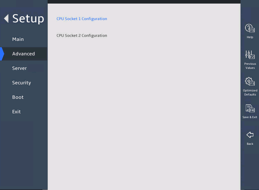
表3-5 Items on the Per-Socket Configuration submenu screen
|
Item |
Description |
|
CPU Socket N Configuration |
Submenu for configuring processor N, as shown in 图3-12. N represents the processor number. The screen displays only present processors. The submenu items are described in 表3-6. |
4. CPU Socket Configuration submenu
图3-12 shows the CPU Socket Configuration submenu screen. The submenu items are described in 表3-6.
This section uses CPU socket 1 as an example.
图3-12 CPU Socket 1 Configuration submenu screen
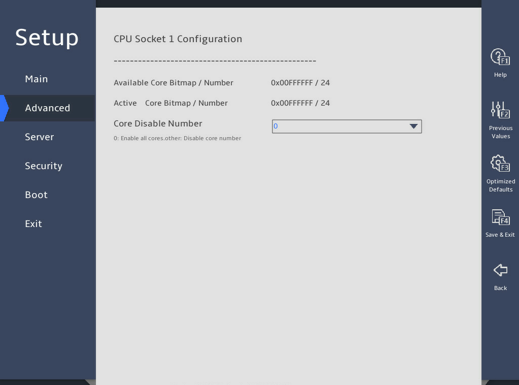
表3-6 Items on the CPU Socket 1 Configuration submenu screen
|
Description |
Default |
|
|
Available Core Bitmap / Number |
Displays the available core bitmap and core quantity. |
N/A |
|
Active Core Bitmap / Number |
Displays the active core bitmap and core quantity. Available core quantity = Active core quantity + Disabled core quantity |
N/A |
|
Core Disable Number |
Select the number of the cores to be disabled. The configuration takes effect after the server starts. To enable all cores of the processor, set the value to 0. You can set the Core Disable Number to a number equal to or less than the available core quantity. For example, if 18 cores are available and 4 cores are disabled, only 14 cores are active. NOTE: Generally, the more cores you enable, the better the computing performance. Please be cautious when you disable cores. |
0 |
5. Common RefCode Configuration submenu
|
|
CAUTION: Be careful to modify the MMCFG Base, MMIO High Base, and MMIO High Granularity Size values. To modify the values, make sure the modification is made based on the requirements of PCIe devices applied. For more information, see the PCIe device configuration guide. |
图3-13 shows the Common RefCode Configuration submenu screen, on which you can configure memory mapped I/O (MMIO) above 4 GB and non-uniform memory access (NUMA) settings as described in 表3-7.
图3-13 Common RefCode Configuration submenu screen
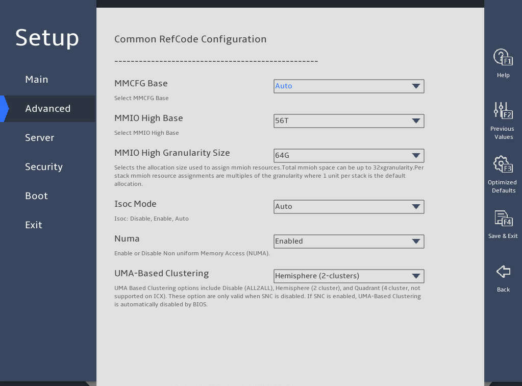
表3-7 Items on the Common RefCode Configuration submenu screen
|
Item |
Description |
Default |
|
MMCFG Base |
This item is not supported by the R6900 G5. Set the memory-mapped I/O (MMIO) low base address for PCIe modules within 4G. When a large number of PCIe devices, especially GPUs, are installed, you can decrease the MMCFG Base value to increase the MMIO low base space. Options include: · 1G. · 1.5G. · 1.75G. · 2G. · 2.25G. · 3G. · Auto. |
Auto. |
|
MMIO High Base |
This item is not supported by the R6900 G5. Set the MMIO high base address for PCIe modules over 4G. Make sure the value is adjusted based on the PCIe devices installed and do not modify the value arbitrarily. Options include: · 56T. · 40T. · 32T. · 24T. · 16T. · 12T. · 4T. · 2T. · 1T. · 512G.
The upper limit of the MMIO high base address is 64T. If the sum size of MMIO high base and size allocated to each stack exceeds 64T, the system hangs at startup. For the B5700, R4300, R4700, R4900, R5300, and R5500 G5, make sure that the sum of MMIO high base and MMIO high granularity size multiplied by 10 is less than 64T. |
· For the R5300 and R5500 G5: 32T. · For the other servers: 56T. |
|
MMIO High Granularity Size |
This item is not supported by the R6900 G5. Set the MMIO high granularity size. By default, the MMIO size allocated to each stack is equal to the specified size. Make sure the value is adjusted based on the requirements of installed PCIe devices on MMIO high base address over 4G and do not change it arbitrarily. If a large number of PCIe devices, especially GPUs, are installed, you can increase the MMIO high granularity size to increase the MMIO high base space, so as to ensure the correct allocation of MMIO high base resources to PCIe devices. Options include: · 1G. · 4G. · 16G. · 64G. · 256G. · 1024G. · 4096G.
The upper limit of the MMIO high base address is 64T. If the sum size of MMIO high base and size allocated to each stack exceeds 64T, the system hangs at startup. For the B5700, R4300, R4700, R4900, R5300, and R5500 G5, make sure that the sum of MMIO high base and MMIO high granularity size multiplied by 10 is less than 64T. |
· For the R5300 and R5500 G5: 4096G. · For the other servers: 64G. |
|
Isoc Mode |
Select whether to enable the Isoc mode. Options: · Enabled. · Disabled. · Auto. |
Auto |
|
Numa |
Select Enabled or Disabled to enable or disable non-uniform memory access (NUMA). Under NUMA, a processor can access its own local memory faster than non-local memory. |
Enabled |
|
UMA-Based Clustering |
Select the UMA-based clustering (UBC) mode. Options include: · Hemisphere (2-clusters)—Enable the UBC mode (also known as Hemisphere (HEMI). This mode allows affinity to exist between memory address and LLC slices to minimize distance memory address and cached LLC. This mode is available only when memory modules are populated in a symmetrical way and SNC is disabled. · Disable (All2All)—Disable the UBC mode. |
Hemisphere (2-clusters) |
6. Uncore Configuration submenu
图3-14 shows the Uncore Configuration submenu screen, on which you can configure Uncore settings as described in 表3-8.
图3-14 Uncore Configuration submenu screen
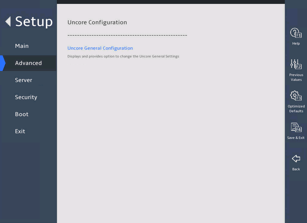
表3-8 Items on the Uncore Configuration submenu screen
|
Item |
Description |
|
Uncore General Configuration |
Submenu for configuring the Uncore General Settings. |
Uncore General Configuration submenu
图3-15 shows the Uncore General Configuration submenu screen, on which you can configure Uncore settings as described in 表3-9.
图3-15 Uncore General Configuration submenu screen
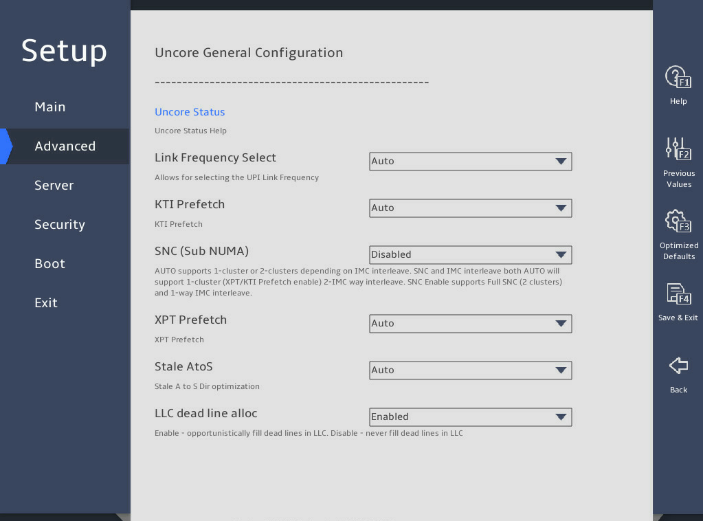
表3-9 Items on the Uncore General Configuration submenu screen
|
Item |
Description |
Default |
|
Uncore Status |
Displays the Uncore status. |
N/A |
|
Link Frequency Select |
Select the UPI link frequency. Options: · 9.6GT/s. · 10.4GT/s. · 11.2GT/s. · Auto. |
Auto |
|
KTI Prefetch |
This item is available only for the R6900 G5. Select whether to enable KTI prefetch. KTI prefetch enables memory read operations on DDR bus to be carried out earlier. Options: · Auto. · Enabled. · Disabled. |
Auto |
|
SNC(Sub NUMA) |
Select whether to enable sub NUMA clustering (SNC). SNC can shorten the delay between the LLC and the memory. For the servers except for the B5700, R4300, R4700, R4900, R5300, and R5500 G5, options: · Enabled. · Disabled. For the B5700, R4300, R4700, R4900, R5300, and R5500 G5, options: · Enable SNC2 (2-clusters)—To enable SNC, make sure the value of the MMCFG Base is an integer, for example, 1, 2, or 3 G. · Disabled. |
Disabled |
|
XPT Prefetch |
Select whether to enable XPT prefetch. Options: · Auto. · Enabled. · Disabled. |
Auto |
|
Stale AtoS |
Select whether to enable the change from state A to S. There are three states of cache directory: I stands for invalid; A stands for snooping all; S stands for shared. State AtoS enables the other rows to enter S state when the system reads from a row in A state and the other rows respond no match. This shortens latency of repeated cache reading without affecting writing and saves bandwidth. As a best practice, enable this feature if there are a lot of reading tasks across the sockets. Options: · Auto. · Enabled. · Disabled. |
Auto |
|
LLC dead line alloc |
Select whether to enable LLC dead line allocation. In the processor cache scheme, mid-level cache (MLC) evictions are filled into the last level cache (LLC). If a line is evicted from the MLC to the LLC, the processor can flag the evicted MLC lines as "dead." This means that the lines are not likely to be read again. This option allows dead lines to be dropped and never fill the LLC if the option is disabled. Options: · Auto. · Enabled—Fills free LLC space with dead rows. · Disabled—Discards dead rows to save LLC space. |
Enabled |
Uncore Status submenu
图3-16 shows the Uncore Status submenu screen, on which you can view the Uncore status as described in 表3-10.
图3-16 Uncore Status submenu screen
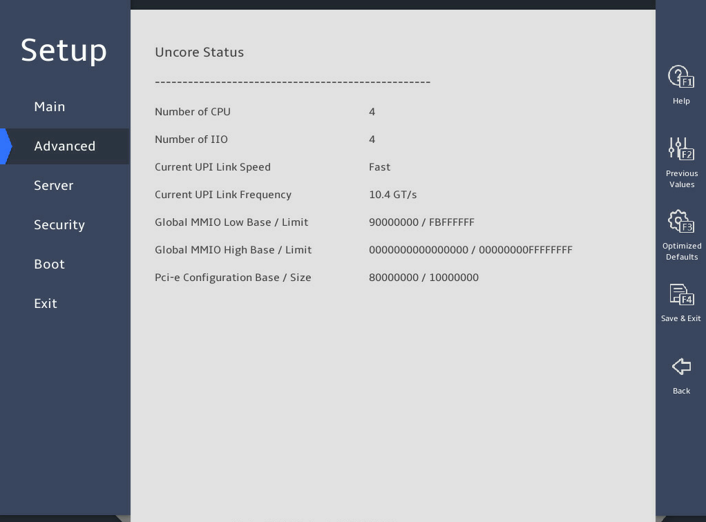
表3-10 Items on the Uncore Status submenu screen
|
Item |
Description |
|
Number of CPU |
Displays the number of CPUs. |
|
Number of IIO |
Displays the number of IIOs. |
|
Current UPI Link Speed |
Displays the link speed of the current UPI. |
|
Current UPI Link Frequency |
Displays the link frequency of the current UPI. |
|
Global MMIO Low Base / Limit |
Displays the low base/limit of the global MMIO. |
|
Global MMIO High Base / Limit |
Displays the high base/limit of the global MMIO. |
|
Pci-e Configuration Base / Size |
Displays the base/size of the UPI PCIe configuration. |
7. Memory Configuration submenu
图3-17 and 图3-18 show the Memory Configuration submenu screen, on which you can configure memory settings such as the memory speed and memory RAS features as described in 表3-11.
图3-17 Memory Configuration submenu screen (1)
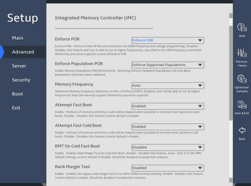
图3-18 Memory Configuration submenu screen (2)
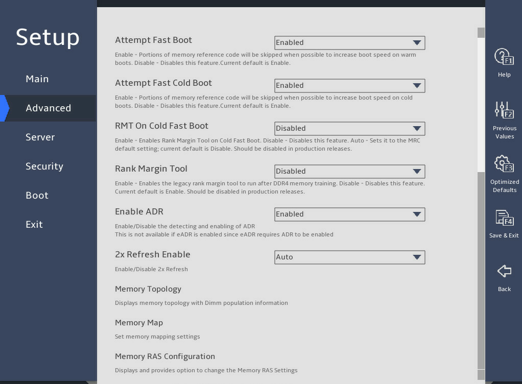
表3-11 Items on the Memory Configuration submenu screen
|
Item |
Description |
Default |
|
Enforce POR |
Select whether to enforce POR restrictions on DDR4 frequency selection to improve memory reliability. Options: · Enforce POR. · Disabled. As a best practice, do not disable this feature. |
Enforce POR |
|
Enforce Population POR |
Specify how to enforce memory population rule. Options: · Disable Enforcement. · Enforce Supported Populations—Fills supported memory, including validated memory and non-validated memory. · Enforce Validated Populations—Only fills validated memory. |
Enforce Supported Populations |
|
Memory Frequency |
Select the maximum memory frequency, in MHz. Options: · Auto. · 2400. · 2666. · 2933. · 3200. |
Auto |
|
Attempt Fast Boot |
Select whether to enable fast boot attempt. Options: · Enabled—Enables fast boot. If skipping part of memory reference code (MRC) can speed up the warm boot process, the system skips this part of MRC. · Disabled—Disables fast boot. |
Enabled |
|
Attempt Fast Cold Boot |
Select whether to enable fast cold boot attempt. Options: · Enabled—Enables fast cold boot. If skipping part of MRC can speed up the cold boot process, the system skips this part of MRC. · Disabled—Disables fast cold boot. |
Enabled |
|
RMT On Cold Fast Boot |
Select whether to enable rank margin tool (RMT) during cold fast boot. Options: · Enabled. · Disabled. |
Disabled |
|
Rank Margin Tool |
Select whether to turn on the Rank Margin Tool to test memory timing and voltage signals. Options: · Enabled—Runs the Rank Margin Tool after memory training. · Disabled—Disables the Rank Margin Tool. |
Disabled |
|
Enable ADR |
Select whether to enable asynchronous DIMM self-refresh (ADR) check. Options: · Enabled. · Disabled. |
Enabled |
|
2x Refresh Enable |
Select whether to enable two times of memory refresh. Options: · Auto. · Enabled. · Disabled. |
Auto |
|
Memory Topology |
Access the submenu that displays memory information, as shown in 图3-19. The submenu items are described in 表3-12. |
N/A |
|
Memory Map |
Access the submenu for configuring memory mapping and interleaving, as shown in. You can enable memory interleaving to improve memory read and write performance. The submenu items are described in 表3-13. |
N/A |
|
Access the submenu for configuring memory reliability, availability, and serviceability (RAS) settings, as shown in 图3-22 and 图3-23. The submenu items are described in 表3-15. |
N/A |
|
|
PMem Configuration |
This item is available only when Barlow Pass (BPS) memory modules are present. Access the submenu for configuring persistent memory (PMem). |
N/A |
Memory Topology submenu
图3-19 shows the Memory Topology submenu screen. The submenu items are described in 表3-12.
图3-19 Memory Topology submenu screen
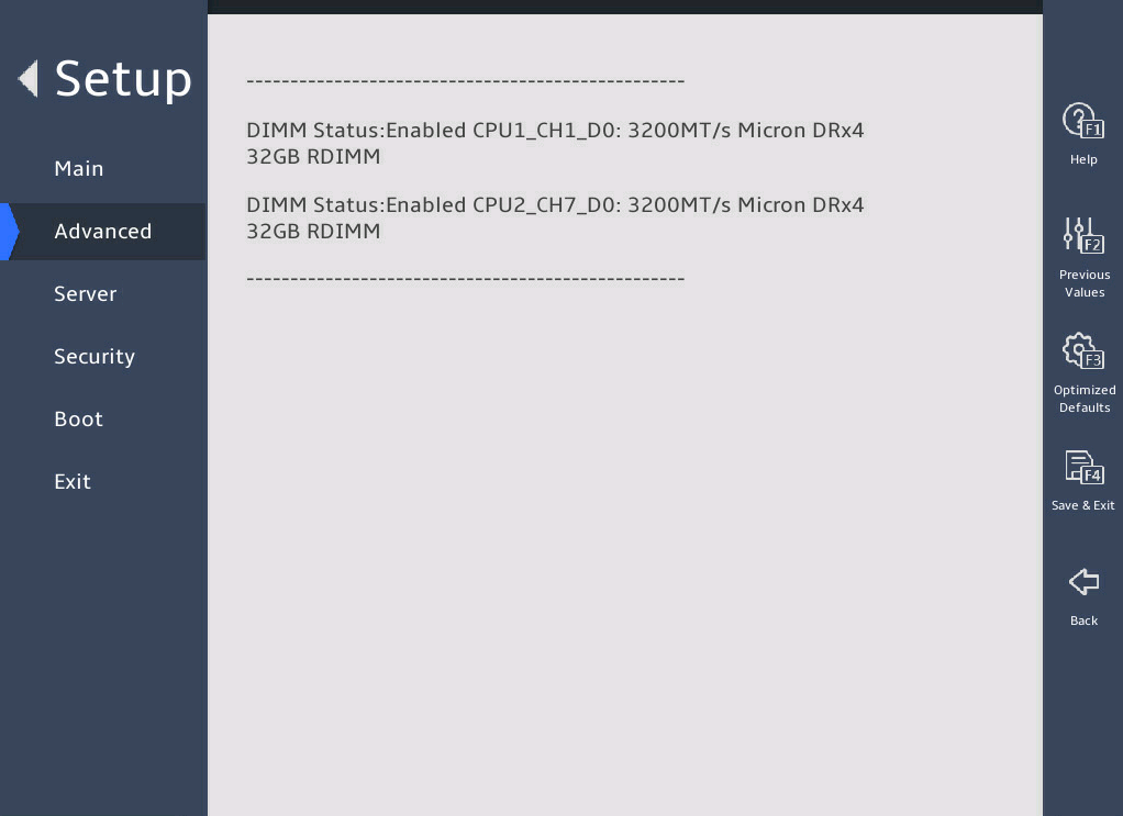
表3-12 Items on the Memory Topology submenu screen
|
Item |
Description |
|
DIMM Status: Enabled CPU1_CH1_D0: 3200MT/s Micron DRx4 32GB RDIMM |
Display the DIMM status, location, and other information. For example, DIMM Status: Enabled CPU1_CH1_D0: 3200MT/s Micron DRx4 32GB RDIMM, where: · DIMM Status: Enabled—DIMM status, which is enabled. · CPU1_CH1_D0—DIMM location, which is DIMM slot 0 of channel 1 for CPU1. · 3200MT/s—DIMM frequency. · Micron—DIMM vendor. · DRx4—DR stands for the number of ranks. x4 indicates the bit width of a DIMM chip. · 32GB—Capacity of the DIMM. · RDIMM—Type of the DIMM. |
Memory Map submenu
图3-20 shows the Memory Map submenu screen for the B5700, R4300, R4700, R4900, R5300, and R5500 G5. The submenu items are described in 表3-13.
图3-20 Memory Map submenu screen (for the B5700, R4300, R4700, R4900, R5300, and R5500 G5)
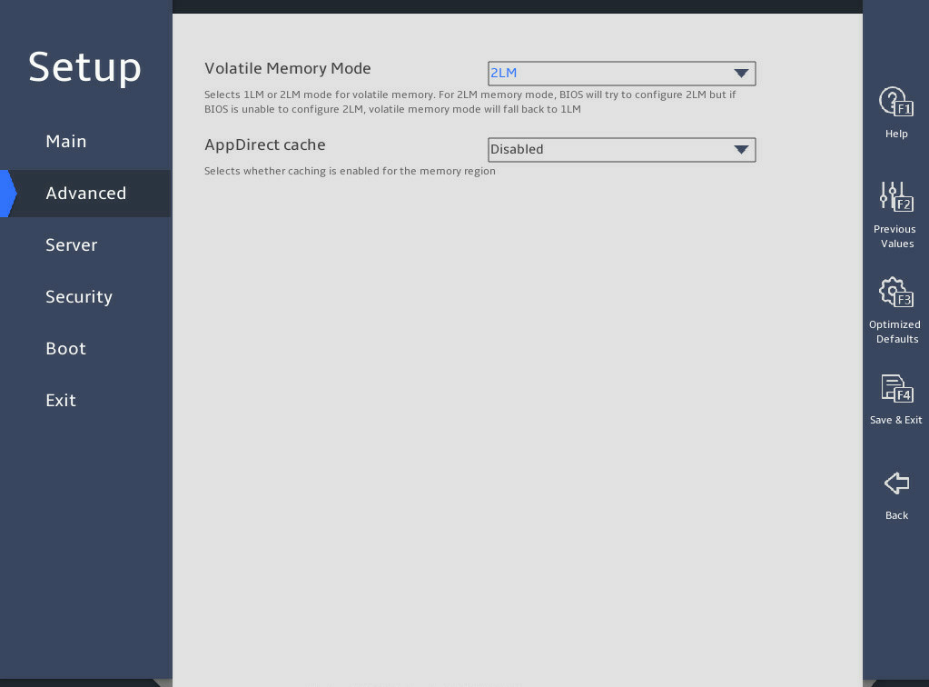
表3-13 Items on the Memory Map submenu screen (for the B5700, R4300, R4700, R4900, R5300, and R5500 G5)
|
Item |
Description |
Default |
|
Volatile Memory Mode |
Set the volatile memory mode for PMem. Options: · 2LM—Sets the 2 Level Memory (2LM) mode. In this mode, 2LM facilitates DDR4 memory as cache and PMem can operate in volatile memory mode. To configure Memory Mode (MM) for PMem, you must also configure settings on the PMem configuration subscreen. · 1LM—Sets the 1 Level Memory (1LM) mode. In this mode, DDR4 memory acts as ordinary memory and PMem can operate in App Direct (AD) mode. |
1LM |
|
AppDirect cache |
Select Enabled or Disabled to enable or disable caching for the memory region. This item is available only when the volatile memory mode is 2LM. |
Disabled |
图3-21 shows the Memory Map submenu screen for the R6900 G5. The submenu items are described in 表3-14.
图3-21 Memory Map submenu screen (for the R6900 G5)
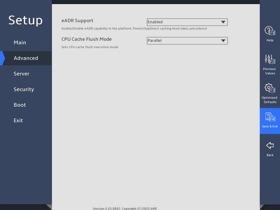
表3-14 Items on the Memory Map submenu screen (for the R6900 G5)
|
Item |
Description |
Default |
|
eADR Support |
Select whether to enable the eADR capability in the platform. Options: · Enabled. · Disabled. · Auto. Do not enable eADR and ADR at the same time. |
Disabled |
|
CPU Cache Flush Mode |
Select the processor cache flush execution mode. Options: · Parallel. · Serial. |
Parallel |
Memory RAS Configuration submenu
图3-22 and 图3-23 show the Memory RAS Configuration submenu screen. The submenu items are described in 表3-15.
图3-22 Memory RAS Configuration submenu screen (1)
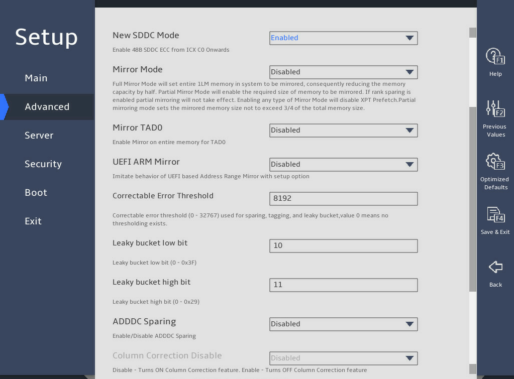
图3-23 Memory RAS Configuration submenu screen (2)
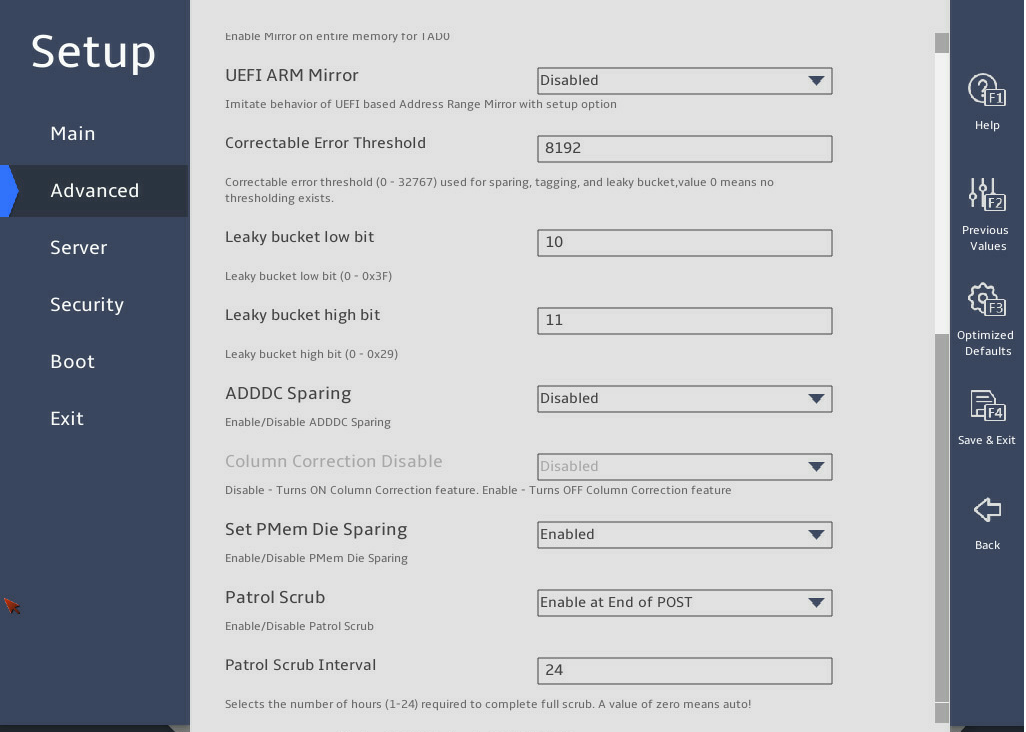
表3-15 Items on the Memory RAS Configuration submenu screen
|
Item |
Description |
Default |
|
New SDDC Mode |
This item is not available for the R6900 G5. Select Enabled or Disabled to enable or disable SDDC mode. |
Enabled |
|
Mirror Mode |
This item is unconfigurable when UEFI ARM Mirror or ADDDC Sparing is set to Enabled. Specify a mirror mode. Options: · Disabled—Disables mirror mode. · Full Mirror Mode—Sets all 1LM memory to operate in mirror mode, which reduces the available memory capacity by half. · Partial Mirror Mode—Enables partial mirror mode. In this mode, you can set the memory size of the mirror. · Due to hardware limitations, a segment of address space must be equally divided among the socket, IMC, Channel and rank. Therefore, when all the DIMMs are present, the memory capacity displayed in the POST screen and BIOS Setup utility is greater than half of the total memory capacity in the full mirror mode. · Enabling any type of mirror mode will disable XPT prefetch. |
Disabled |
|
Partial Mirror x Size(GB) |
This item is available only when the Mirror Mode is set to Partial Mirror Mode. Set the size of the partial mirror. |
N/A |
|
Mirror TAD0 |
This item is unconfigurable when Mirror Mode is set to Full Mirror Mode or ADDDC Sparing is set to Enabled. Select Enabled or Disabled to enable or disable the mirror target address decoder (TAD0) mode. If Enabled is selected, the memory saved for MMIO will be used for mirroring. |
Disabled |
|
UEFI ARM Mirror |
This item is unconfigurable when Mirrorr Mode is not disabled or ADDDC Sparing is set to Enabled. Select Enabled or Disabled to enable or disable UEFI ARM mirror mode. |
Disabled |
|
ARM Mirror percentage |
Set the ARM mirror percentage. For example, 12.75% can be written as 1275. |
N/A |
|
Correctable Error Threshold |
Set the correctable error threshold in decimal notation. Value range: 0 to 32767. Value 0 indicates that no correctable error threshold is set. |
8192 |
|
Leaky bucket low bit |
This item is configurable only when Memory Rank Sparing is set to Enabled. Set the leaky bucket low bit in the range of 0 to 0x3F in hexadecimal notation. |
0x10 |
|
Leaky bucket high bit |
This item is configurable only when Memory Rank Sparing is set to Enabled. Set the leaky bucket high bit in the range of 0 to 0x29 in hexadecimal notation. |
0x11 |
|
ADDDC Sparing |
This item is unconfigurable when Mirror Mode is set to Partial Mirror Mode or Full Mirror Mode. Select Enabled or Disabled to enable or disable adaptive double device data correction (ADDDC) sparing. ADDDC sparing can correct data errors on two memory chips and is available only for x4 memory. After modification, you must perform a cold reboot for the new ADDDC Sparing setting to take effect. NOTE: For the change to take effect, perform cold reboot. |
· For the R4300 G5 and R6900 G5: Enabled · For the other servers: Disabled |
|
Plus One |
This item is available only for the R6900 G5. Select Enabled or Disabled to enable or disable the SDDC. |
Disabled |
|
Enable ADDDC Error Injection |
This item is available only when ADDDC Sparing is set to Enabled. Select Enabled or Disabled to enable or disable ADDDC error injection. |
Enabled |
|
Column Correction Disable |
This item is available only when ADDDC Sparing is set to Enabled. Select Enabled or Disabled to disable or enable column correction. |
Disabled |
|
Set PMem Die Sparing |
Select Enabled or Disabled to enable or disable the PMem Die sparing. |
Enabled |
|
ECC Mode Switch |
This item is available only for the R6900 G5. Select Enabled or Disabled to enable or disable remote memory controller mode to switch from A to B. |
Enabled |
|
Patrol Scrub |
This item enables or disables patrol scrubbing. · Enabled—Enables patrol scrubbing. · Disabled—Disables patrol scrubbing. · Enable at End of POST—Enables patrol scrubbing after POST. Patrol scrubbing allows a processor to automatically search for and correct correctable memory errors at regular intervals. |
Enable at End of POST |
|
Patrol Scrub Interval |
Set the patrol scrub interval in hours. This item is available only when Patrol Scrub is set to Enabled. An interval of 0 indicates auto patrol scrubbing. |
24 |
PMem Configuration submenu
图3-24 and 图3-25 show the PMem Configuration submenu screen. The submenu items are described in 表3-16.
图3-24 PMem Configuration submenu screen (1)
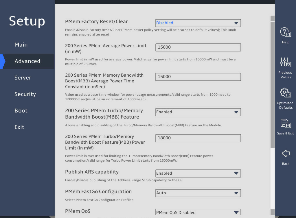
图3-25 PMem Configuration submenu screen (2)
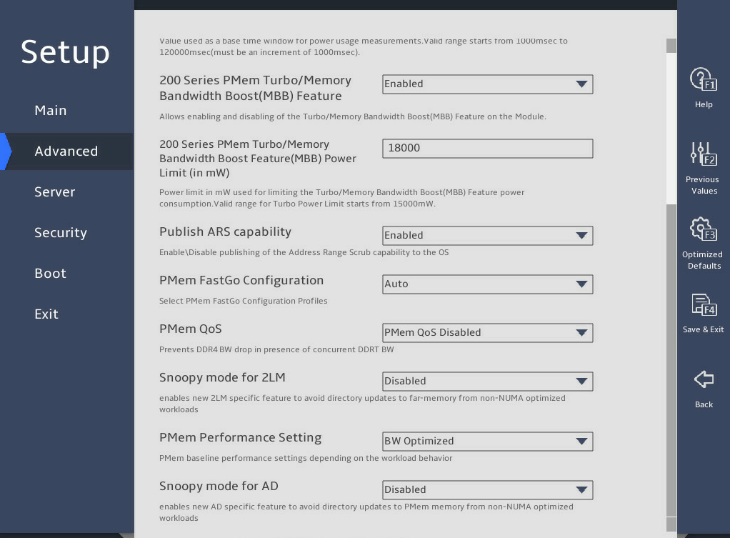
表3-16 Items on the PMem Configuration submenu screen
|
Item |
Description |
Default |
|
PMem Factory Reset/Clear |
Select Enabled or Disabled to enable or disable PMem factory reset/clear. Options: · Enabled—Enables PMem factory reset/clear. The average power budget setting will override the default average power budget. · Disabled—Disables PMem factory reset/clear. |
Disabled |
|
200 Series PMem Average Power Limit(in mW) |
Set the 200 series PMem average power limit in mW. The value starts from 10000 mW and must be a multiple of 250 mW. The average power limit range varies by the capacity of NVDIMM. If the capacity is 128G, the power limit range is 10 W to 15 W. If the capacity is 256 or 512 GB, the power limit range is 12 W to 18 W. If you set a value out of the range, the system corrects the value automatically. |
15000 |
|
200 Series PMem Turbo/Memory Bandwidth Boost(MBB) Average Power Time Constant(in mSec) |
Set the 200 series PMem average power time constant in mSec as the base time window for measuring the average power. The value is in the range of 10000 ms to 120000 ms and increases in a step size of 1000 ms. |
15000 |
|
200 Series PMem Turbo/Memory Bandwidth Boost(MBB) Feature |
Select Enabled or Disabled to enable or disable 200 series PMemTurbo/memory bandwidth boost (MBB). |
Enabled |
|
200 Series PMem Turbo/Memory Bandwidth Boost Feature(MBB) Power Limit(in mW) |
Set 200 series PMem memory bandwidth boost (MBB) power limit, in mW. |
18000 |
|
Publish ARS capability |
Select Enabled or Disabled to enable or disable the publishing of address range scrubbing (ARS). If Enabled is selected, ARS allows the system software to check memory errors, so as to avoid access that may lead to uncorrectable memory errors in advance, and allows memory errors to be counted. |
Enabled |
|
PMem FastGo Configuration |
Select PMem FastGo configuration profiles. Options: · Auto. · Enabled FastGo optimization. · Disabled FastGo optimization. |
Auto |
|
PMem QoS |
Set PMem Quality of Service (QoS) to prevent DDR4 BW drop in case of DDRT BW concurrency. Options: · PMem QoS Disabled. · Profile 1 – Optimized for 8 PMem modules per socket. · Profile 2 – Optimized for 4/2/1 PMem modules per socket. |
PMem Qos Disabled |
|
Snoopy mode for 2LM |
Enable the snoopy mode for 2LM to avoid direct updates to far-memory from non-NUMA optimized workloads. Options: · Enabled. · Disabled. |
Disabled |
|
PMem Performance Setting |
Options: · BW Optimized. · Balanced Profile. |
BW Optimized |
|
Snoopy mode for AD |
Enable the snoopy mode for AD to avoid direct updates to PMem memory from non-NUMA optimized workloads. Options: · Enabled. · Disabled. |
Disabled |
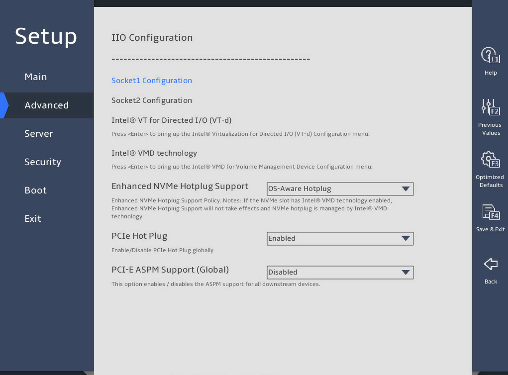
8. IIO Configuration submenu
图3-26 shows the IIO Configuration submenu screens, on which you can configure the peripheral component interconnect express (PCIe) slots, including their link speed and maximum payload size, as described in 表3-17.
图3-26 IIO Configuration submenu screen

表3-17 Items on the IIO Configuration submenu screen
|
Item |
Description |
Default |
|
SocketN Configuration |
This item is available only when the processor is present. Display the IIO configuration of processor N. |
N/A |
|
Intel® VT for Directed I/O (VT-d) |
Displays the configuration menu for Intel® VT. |
N/A |
|
Intel VMD technology |
Displays the configuration menu for Intel®VMD. |
N/A |
|
Enhanced NVMe Hotplug Support |
This item is not available for the R6900 G5. Set the enhanced NVMe hot plug support policy. Options: · OS-Aware Hotplug. · OS-Aware & Sruprise Hotplug. |
OS-Aware Hotplug |
|
IIO-PCIE Express Global Options |
||
|
PCIe Hot Plug |
Select whether to enable or disable PCIe hot plug. Options: · Enabled—Enables global PCIe hot plug. · Disabled—Disables global PCIe hot plug. · Auto—Sets PCIe hot plug automatically. This option is available only for the R6900 G5. · Manual—Sets PCIe hot plug manually. This option is available only for the R6900 G5. |
Enabled |
|
PCI-E ASPM Support (Global) |
Select whether to enable PCIe ASPM globally. Options: · Disabled—Disables PCIe ASPM globally. · Per-Port—Controls PCIe ASPM per port. · L1 Only—Supports PCIe ASPM only on L1. |
Disabled |
Socket Configuration submenu
The Socket Configuration submenu displays link parameters and status for PCIe ports, and provides options for managing each PCIe port, such as port enabling, link speed selection, and hot swapping enabling.
The Socket Configuration submenu screen varies by server model and PCIe riser card model. The following uses Socket 1 Configuration for example.
图3-27 shows the Socket 1 Configuration submenu screen. The submenu items are described in 表3-18.
图3-27 Socket 1 Configuration submenu screen
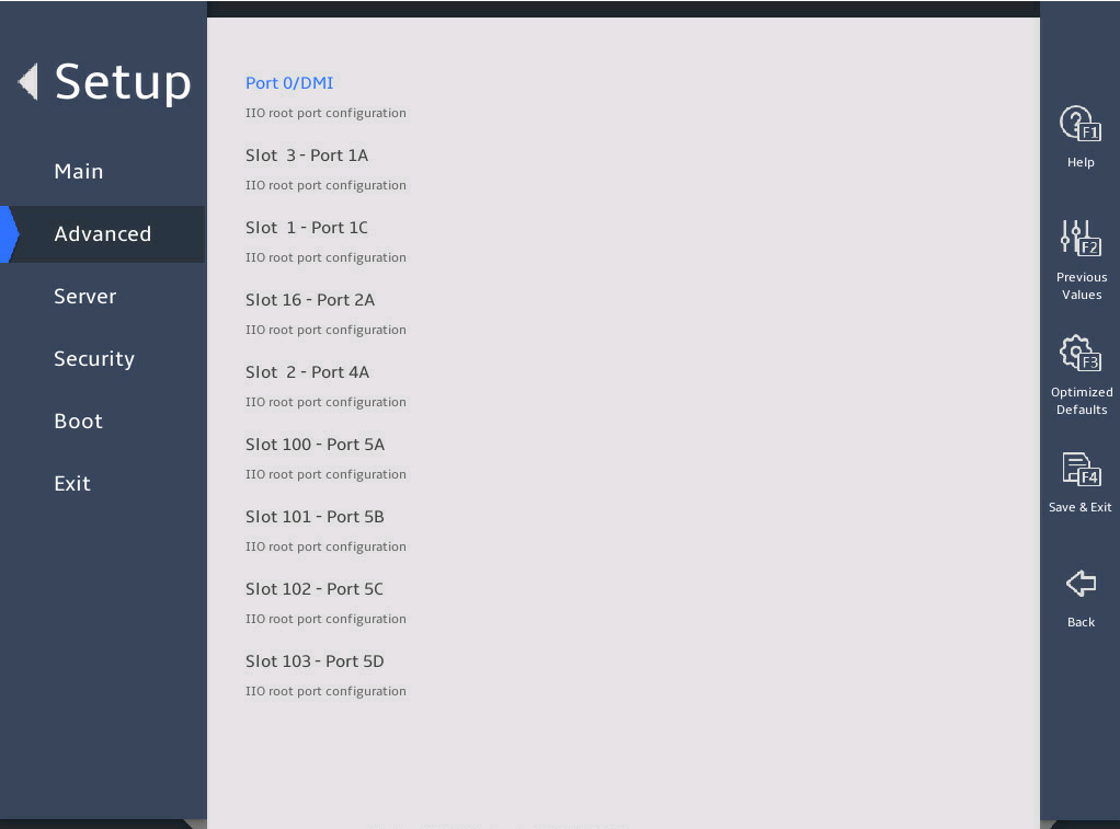
表3-18 Items on the Socket 1 Configuration submenu screen
|
Item |
Description |
Default |
|
Port 0/DMI |
Displays the configuration menu for Port 0/DMI. DMI is the interface between the CPU and the PCH. |
N/A |
|
Slot 3 - Port 1A |
Displays the configuration menu for Port 1A. Slot 3 indicates the slot ID of the device connected to the PCIe slot. |
N/A |
The following takes Slot 3 – Port 1A for example.
图3-28 and 图3-29 show the Port Configuration submenu screen. The submenu items are described in 表3-19.
图3-28 Port Configuration submenu screen (1)
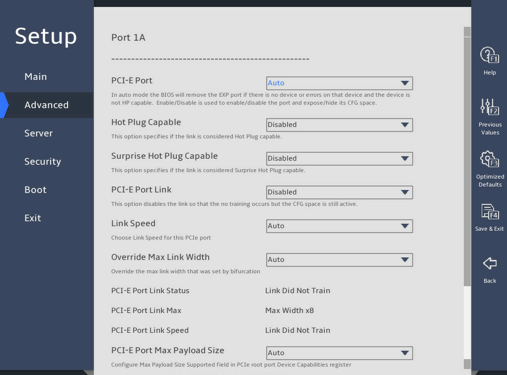
图3-29 Port Configuration submenu screen (2)
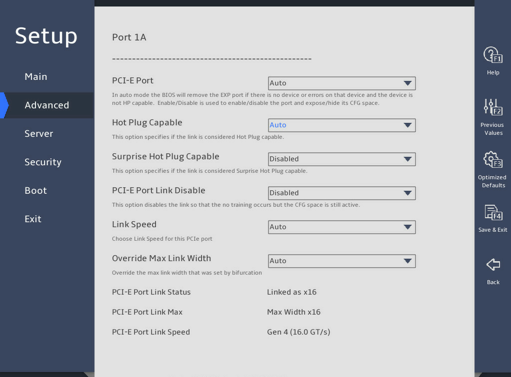
表3-19 Items on the Port Configuration submenu screen
|
Item |
Description |
Default |
|
PCI-E Port |
This item is available only for non-DMI PCIe ports. Select whether to enable the PCIe port. Options: · Auto. · Enabled. · Disabled. |
Auto |
|
Hot Plug Capable |
Select whether to enable hot plug. Options: · Auto. · Enabled. · Disabled. |
· R6900 G5: Disabled · Other servers: Auto |
|
Surprise Hot Plug Capable |
Select Enabled or Disabled to enable or disable surprise hot plug. |
Disabled |
|
PCI-E Port Link Disable |
Select whether to enable the PCIe port link. · Enabled—Enables the PCIe port link. · Disabled—Disables the PCIe port link and link training. The PCIe configuration space is still active. |
Disabled |
|
Link Speed |
Select a link speed for the PCIe port. Options: · Auto. · Gen 1 (2.5 GT/s). · Gen 2 (5.0 GT/s). · Gen 3 (8.0 GT/s). · Gen 4 (16.0 GT/s)—Supported only by IceLake processors. |
Auto |
|
Override Max Link Width |
Select a maximum link width to be covered. Options: · Auto. · x1. · x2. · x4. · x8. · x16. |
Auto |
|
PCI-E Port Link Status |
Displays the PCIe port link status. |
N/A |
|
PCI-E Port Link Max |
Displays the maximum bandwidth of the PCIe port link. |
N/A |
|
PCI-E Port Link Speed |
Displays the PCIe port link speed. |
N/A |
|
PCI-E Port Max Payload Size |
This item is available only for the R6900 G5. Set the maximum payload size of the PCIe port. Options: · Auto—Sets the maximum payload size to 256B by default. · 128B—Sets the maximum payload size to 128B. The configuration might affect the performance of NVMe drives. You can set the maximum payload size of a PCIe port to 128B if NVMe drive hot swapping causes the system to reboot. · 256B—Sets the maximum payload size to 256B. |
Auto |
|
PCI-E ASPM Support |
This item is available only for the R6900 G5. Select whether to enable support for PCIe active-state power management (ASPM). If the PCIe device is not in use, ASPM controls the power status at both ends of the PCIe link to save power. Options: · Auto—CPU auto. · L1 Only—Only L1 is supported. · Disabled—Disables PCIe ASPM. |
L1 Only |
|
PM ACPI Mode |
This item is available only for the R6900 G5. Select Enabled or Disabled to enable or disable PM ACPI mode. |
Disabled |
Intel® VT for Directed I/O (VT-d) submenu
图3-30 shows the Intel® VT for Directed I/O (VT-d) submenu screen for the R6900 G5. The submenu items are described in 表3-20.
图3-30 Intel® VT for Directed I/O (VT-d) submenu screen (for the R6900 G5)
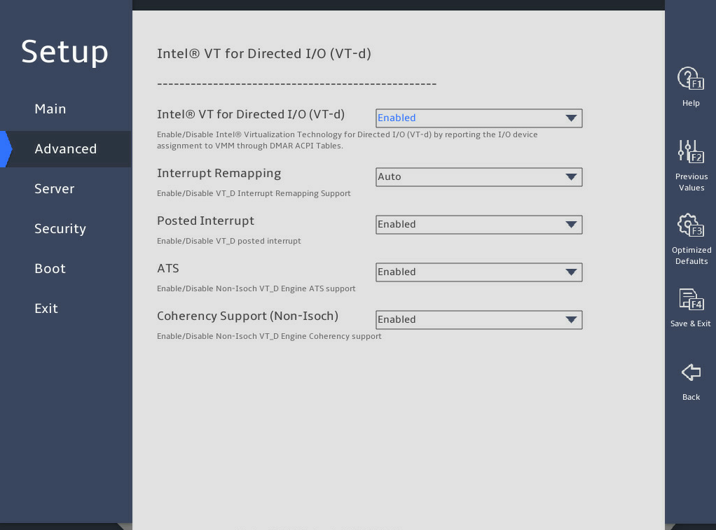
表3-20 Items on the Intel® VT for Directed I/O (VT-d) submenu screen (for the R6900 G5)
|
Item |
Description |
Default |
|
Select Enabled or Disabled to enable or disable Intel virtualization technology for directed I/O (VT-d). With this feature enabled, management programs and OSs that support this feature can provide directed I/O with hardware support offered by the Intel virtualization technology. You can enable this feature even if such management programs and OSs are not used. Intel VT-d enhances system security and reliability, and improves the performance of I/O devices in a virtualized environment. |
Enabled |
|
|
Interrupt Remapping |
Select whether to enable interrupt remapping. Options: · Auto. · Enabled. · Disabled. |
Auto |
|
Posted Interrupt |
Select Enabled or Disabled to enable or disable posted interrupt. |
Enabled |
|
ATS |
Select Enabled or Disabled to enable or disable non-Isoch VT-d engine address translation services (ATS). |
Enabled |
|
Coherency Support(Non-Isoch) |
Select Enabled or Disabled to enable or disable support for non-Isoch coherency. |
Enabled |
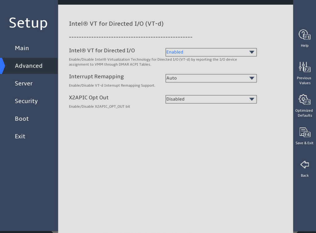
图3-31 shows the Intel® VT for Directed I/O (VT-d) submenu screen for the B5700, R4300, R4700, R4900, R5300, and R5500 G5. The submenu items are described in 表3-21.
|
Item |
Description |
Default |
|
Intel® VT for Directed I/O (VT-d) |
Select Enabled or Disabled to enable or disable Intel virtualization technology for directed I/O (VT-d). With this feature enabled, management programs and OSs that support this feature can provide directed I/O with hardware support offered by the Intel virtualization technology. You can enable this feature even if such management programs and OSs are not used. Intel VT-d enhances system security and reliability, and improves the performance of I/O devices in a virtualized environment. |
Enabled |
|
Interrupt Remapping |
Select whether to enable interrupt remapping. Options: · Auto. · Enabled. · Disabled. |
Auto |
|
X2APIC Opt Out |
Select Enabled or Disabled to enable or disable X2APIC opt out for VT-d. |
Disabled |
Intel® VMD technology submenu
图3-32 shows the Intel® VMD technology submenu screen. The submenu items are described in 表3-22.
图3-32 Intel® VMD technology submenu screen
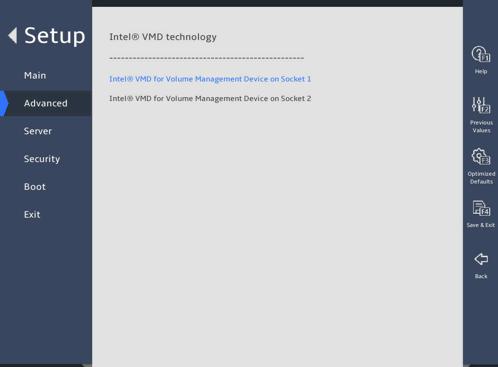
表3-22 Items on the Intel® VMD technology submenu screen
|
Item |
Description |
|
Intel® VMD for Volume Management Device on Socket n |
Displays VMD configuration submenu for the volume management device on a processor. This item is available only when a processor is in position. |
The configurable parameters on the Intel® VMD for Volume Management Device on Socket submenu are the same for different processors. The following takes Socket 1 for example, as shown in 图3-33. The submenu items are described in 表3-23.
图3-33 Intel® VMD for Volume Management Device on Socket 1 submenu screen
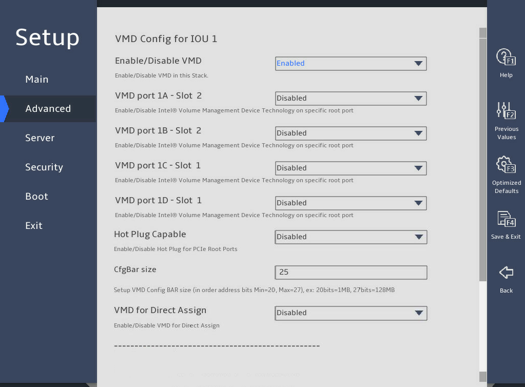
表3-23 Items on the Intel® VMD for Volume Management Device on Socket submenu screen
|
Item |
Description |
Default |
|
VMD Config for PCH/IOU n |
Indicates that the following VMD settings are for PCH or IOU port N. |
NA |
|
Enable/Disable VMD |
Select Enabled or Disabled to enable or disable the VMD feature on the PCH or IOU port. VMD is available only in UEFI mode. Options: · Disabled. · Enabled—The following fields will be displayed only when VMD is enabled. |
· B5700 G5: Enabled for the VMD Config for IOU 4 submenu · Other servers: Disabled |
|
VMD port nA/B/C/D – Slot x |
Select Enabled or Disabled to enable or disable the VMD on the port. The slot ID indicates the slot of the device connected to the port, which is decided by the riser card and the NVMe backplane. |
Disabled |
|
Hot Plug Capable |
Select Enabled or Disabled to enable or disable hot plug on the port. |
Disabled |
|
CfgBar Size |
Sets the size of the configured BAR, in bits. The value range of 20 to 27. |
25 |
9. Advanced Power Management Configuration submenu
图3-34 shows the Advanced Power Management Configuration submenu screen, on which you can configure advanced power management parameters, including P state control and C state control for processors and power management policy.
The submenu items are described in 表3-24.
图3-34 Advanced Power Management Configuration submenu screen
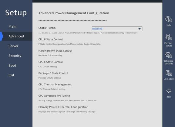
表3-24 Items on the Advanced Power Management Configuration submenu screen
|
Item |
Description |
|
Static Turbo |
Configure the static turbo feature. Options include the following: · Disable—Disable the static turbo feature. This is the default value. · Manual—Enable the static turbo feature and allow the user to select a frequency. · Auto—Enable the static turbo feature and use the MaxCore maximum turbo frequency. In a Windows Server or CentOS 7 operating system, this feature is configurable only when the high performance mode is enabled. |
|
CPU Frequency Select |
Specify a CPU frequency. This parameter is displayed when you select Manual or Auto for the Static Turbo parameter. · When you select Manual for the Static Turbo parameter, you can specify a frequency in the range of the base clock to the MaxCore maximum turbo frequency. The default value is 40, and the unit is 100 MHz. If you specify a frequency smaller than the base clock, the base clock is used. If you specify a frequency larger than the supported MaxCore maximum turbo frequency, the MaxCore maximum turbo frequency is used. · When you select Auto for the Static Turbo parameter, this parameter is not configurable and displays the MaxCore maximum turbo frequency of the current CPU model. |
|
CPU P State Control |
Submenu for configuring CPU P-state control options, as shown in 图3-35 and 图3-36. On the submenu, you can select whether to enable Enhanced Intel SpeedStep Technology (EIST) and turbo mode as described in 表3-25. |
|
Hardware PM State Control |
Submenu for configuring hardware P-state control options, as shown in 图3-37. The submenu items are described in 表3-26. |
|
CPU C State Control |
Submenu for configuring CPU C-state control options, as shown in 图3-38. On the submenu, you can control the power consumption of CPUs in idle state as described in 表3-27. |
|
Package C State Control |
Submenu for configuring package C state control options, as shown in 图3-39. On the submenu, you can set the C2 to C3 state transition timer as described in 表3-28. |
|
CPU Thermal Management |
Submenu for configuring CPU thermal management options, as shown in 图3-40. The submenu items are described in 表3-29. |
|
CPU Advanced PM Tuning |
Submenu for configuring CPU advanced power management tuning, as shown in 图3-42. The submenu items are described in 表3-31. |
|
Memory Power & Thermal Configuration |
Submenu for configuring memory power and thermal, as shown in 图3-44. The submenu items are described in 表3-33. |
CPU P State Control submenu
图3-35 and 图3-36 show the CPU P State Control submenu screen. The submenu items are described in 表3-25.
图3-35 CPU P State Control submenu screen (1)
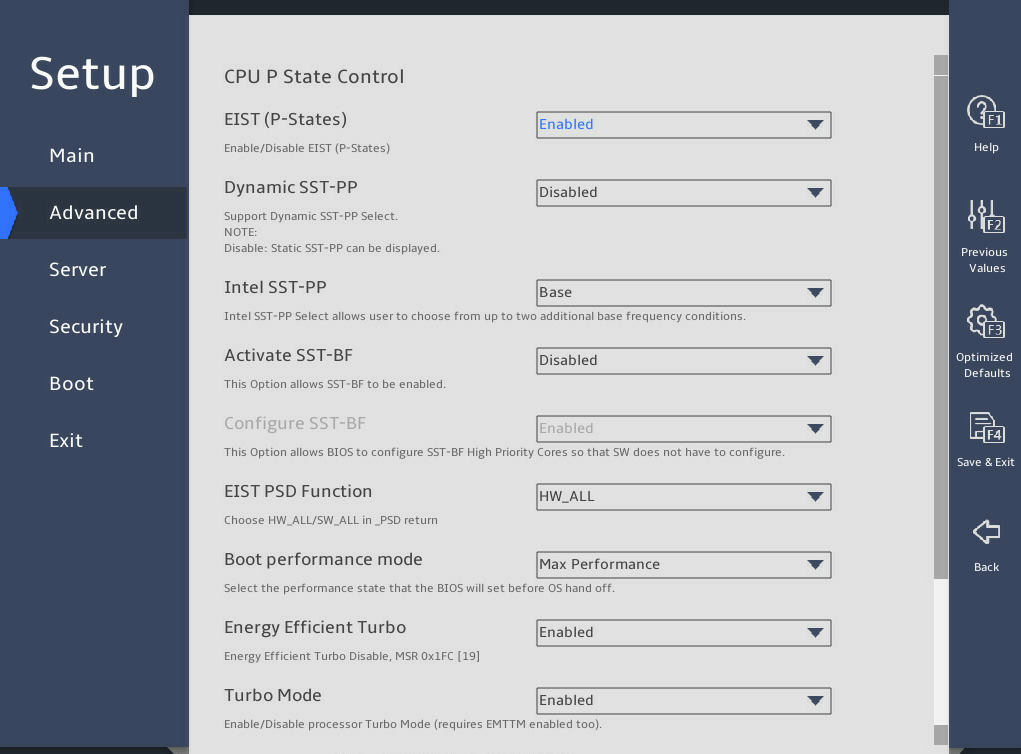
图3-36 CPU P State Control submenu screen (2)
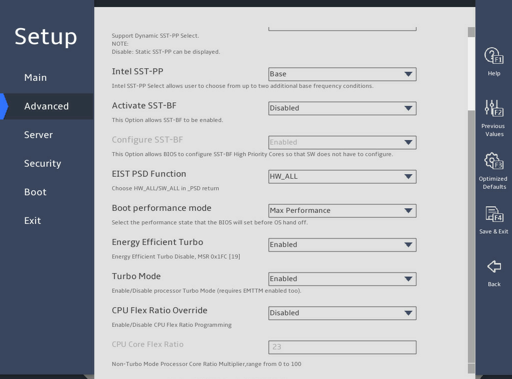
表3-25 Items on the CPU P State Control submenu screen
|
Description |
Default |
|
|
EIST (P-States) |
Select Enabled or Disabled to enable or disable Enhanced Intel SpeedStep Technology (EIST). EIST allows the system to automatically adjust its performance states (P-States) to reduce power consumption and heat dissipation by lowering processor voltage and core frequency. |
Enabled |
|
Dynamic SST-PP |
Availability of this item depends on the processor model. Select Enabled or Disabled to enable or disable dynamic Speed Select Technology-Performance Profile (SST-PP). Dynamic SST-PP allows dynamic configuration of processors. |
Disabled |
|
Intel SST-PP |
Availability of this item depends on the processor model. This item is available only when Dynamic SST-PP is set to Disabled. Configure static SST-PP. Options: · Base. · Config 3. · Config 4. |
Base |
|
Activate SST-BF |
Availability of this item depends on the processor model. Select Enabled or Disabled to enable or disable Speed Select Technology- Base Frequency (SST-BF). SST-BF improves the base frequency of cores for high-priority workloads and reducing the base frequency of cores for low-priority workloads, which improves the overall performance. |
Disabled |
|
Configure SST-BF |
Availability of this item depends on the processor model. Select whether to enable the BIOS to configure SST-BF settings. Options: · Enabled—Enables the BIOS to configure SST-BF high priority cores. · Disabled. |
Enabled |
|
Config TDP Lock |
Select Enabled or Disabled to enable or disable Thermal Design Power (TDP) lock for the processor. |
Enabled |
|
EIST PSD Function |
Set the method for EIST to automatically adjust processor voltage and core frequency to reduce power consumption and help heat dissipation. Options: · HW_ALL—Specifies all the hardware. · SW_ALL—Specifies all the software. |
HW_ALL |
|
Boot performance mode |
Set the boot performance state for BIOS before the OS takes over. Options: · Max Performance. · Max Efficient. · Set by Intel Node Manager. |
Max Performance |
|
Energy Efficient Turbo |
Select Enabled or Disabled to enable or disable energy efficient Turbo mode. |
Enabled |
|
Turbo Mode |
Select Enabled or Disabled to enable or disable the Turbo mode. |
Enabled |
|
CPU Flex Ratio Override |
Select Enabled or Disabled to enable or disable setting processor flex ratio. |
Disabled |
|
CPU Core Flex Ratio |
This item is configurable only when CPU Flex Ratio Override is set to Enabled. Set the processor core ratio multiplier, in the range of 0 to 100, to limit the maximum operating frequency of a processor. For example, if the multiplier is 32, the maximum operating frequency is 3200 MHz. If Turbo is disabled, the maximum operating frequency of a processor will not exceed the limit. |
23 |
Hardware PM State Control submenu
图3-37 shows the Hardware PM State Control submenu screen. The submenu items are described in 表3-26.
图3-37 Hardware PM State Control submenu screen
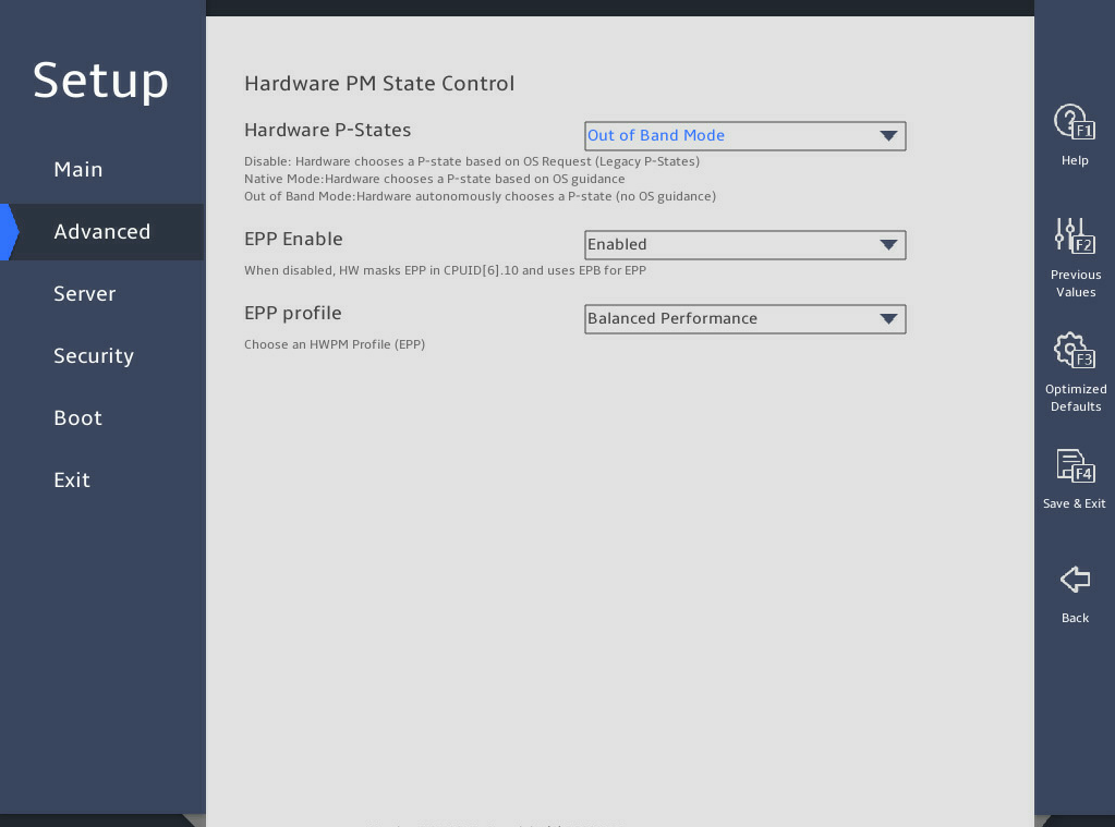
表3-26 Items on the Hardware PM State Control submenu screen
|
Item |
Description |
Default |
|
Hardware P-States |
Set the mode for selecting the hardware P-states. Options: · Disabled—Disables the hardware P-state feature. · Native Mode—Allows direct register access from the OS for CPU configuration. Both the legacy ACPI table (_pct\pss\ppc) and new ACPI specification (_CPC V2) are supported. · Out of Band Mode—Allows only out-of-band management by using BMC. In this mode, you cannot access the hardware P-state register from the OS. · Native Mode with No Legacy Support—This mode is the same as the native mode except for support of the new ACPI specification (_CPC V2). |
Native Mode |
|
EPP Enable |
This item is unconfigurable when Hardware P-States is set to Disabled. Select Enabled or Disabled to enable or disable ENERGY_PERFORMANCE_PREFERENCE (EPP). If this feature is disabled, the system uses ENEGY_PERF_BIAS (EPB). |
Enabled |
|
EPP profile |
This item is unconfigurable when Hardware P-States is set to Disabled. Set the EPP mode. Options: · Performance—Provides maximum system performance at the expense of energy efficiency. · Balanced Performance—Provides optimum performance with good energy efficiency. · Balanced Power—Provides optimum power efficiency with good performance. · Power—Provides maximum power efficiency (maximum power saving) at the expense of system performance. |
Balanced Performance |
CPU C State Control submenu
图3-38 shows the CPU C State Control submenu screen. The submenu items are described in 表3-27.
图3-38 CPU C State Control submenu screen
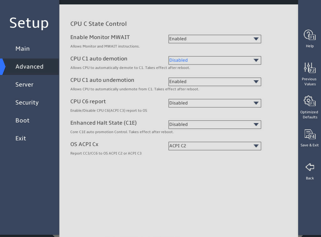
表3-27 Items on the CPU C State Control submenu screen
|
Description |
Default |
|
|
Enable Monitor MWAIT |
Select Enabled or Disabled to enable or disable Monitor/Mwait instructions. Enabling Monitor/Mwait instructions optimizes processor instruction execution. To disable CPU C state, you must also disable Monitor MWAIT for some operating systems. If Enhanced vMotion Compatibility (EVC) errors occur during VM adding to a cluster or VM service migration, enable this feature. |
Enabled |
|
CPU C1 auto demotion |
Select whether to enable processors to automatically demote to C1. Options: · Enabled—Enables processors to automatically demote to C1. · Disabled—Disables processors from automatically demoting to C1. |
Disabled |
|
CPU C1 auto undemotion |
Select whether to enable processors to automatically undemote from C1. Options: · Enabled—Enables processors to automatically undemote from C1. · Disabled—Disables processors from automatically undemoting from C1. |
Enabled |
|
CPU C6 Report |
Select whether to enable the BIOS to report the C6 state to the operating system. Options: · Enabled—Enables the BIOS to report the C6 state to the operating system. · Disabled—Disables the BIOS from reporting the C6 state to the operating system. · Auto—Enables the BIOS to report the C6 state to the operating system by default. |
Disabled |
|
Enhanced Halt State (C1E) |
Select Enabled or Disabled to enable or disable the C1E feature. C1E feature enables a processor to operate at the minimum performance state in idle time to reduce power consumption. The C1E configuration takes effect after the server restarts. |
Disabled |
|
OS ACPI Cx |
Select the ACPI to which the system reports C3/C6. Options: · ACPI C2. · ACPI C3. |
ACPI C2 |
Package C State Control submenu
图3-39 shows the Package C State Control submenu screen. The submenu items are described in 表3-28.
图3-39 Package C State Control submenu screen

表3-28 Items on the Package C State Control submenu screen
|
Item |
Description |
Default |
|
Select the package C state limit. Options: · C0/C1 state. · C2 state. · C6 (non Retention)state. · C6 (Retention) state. · No Limit. · Auto. |
C0/C1 state |
|
|
Dynamic L1 |
This item is not available for the R6900 G5. Select Enabled or Disabled to enable or disable the dynamic L1. |
Enabled |
|
C2C3TT |
This item is available only for the R6900 G5. Set the C2 status to C3 status event counter, in µs. Setting the value to 0 enables the BIOS to set the counter automatically. |
0 |
|
PKG C-state Lat. Neg. |
Select Enabled or Disabled to enable or disable the package C-state latency negotiation feature. |
· R6900 G5: Disabled · Other servers: Enabled |
CPU Thermal Management submenu
图3-40 shows the CPU Thermal Management submenu screen. The submenu items are described in 表3-29.
图3-40 CPU Thermal Management submenu screen
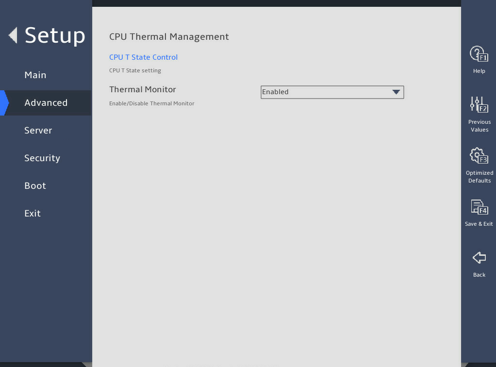
表3-29 Items on the CPU Thermal Management submenu screen
|
Item |
Description |
Default |
|
CPU T State Control |
CPU T-state control submenu, as shown in 图3-41. The submenu items are described in 表3-30. |
N/A |
|
Thermal Monitor |
Select Enabled or Disabled to enable or disable processor temperature monitoring. |
Enabled |
CPU T State Control submenu
图3-41 shows the CPU T State Control submenu screen. The submenu items are described in 表3-30.
图3-41 CPU T State Control submenu screen
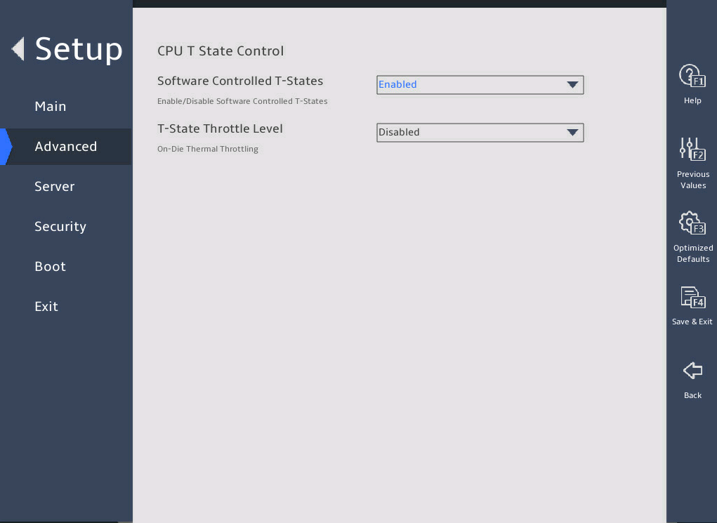
表3-30 Items on the CPU T State Control submenu screen
|
Item |
Description |
Default |
|
Select Enabled or Disabled to enable or disable software controlled T-state. |
Disabled |
|
|
T-State Throttle Level |
This item is available only when Software Controlled T-State is set to Enabled. Select the T-state throttle level. Options: · Disabled—Disables T-state throttling. · 6.25%. · 12.5%. · 18.75%. · 25.0%. · 31.25%. · 37.5%. · 43.75%. · 50.0%. · 56.25%. · 62.5%. · 68.75%. · 75.0%. · 81.25%. · 87.5%. · 93.75%. |
Disabled |
CPU Advanced PM Tuning submenu
图3-42 shows the CPU Advanced PM Tuning submenu screen. The submenu items are described in 表3-31.
图3-42 CPU Advanced PM Tuning submenu screen
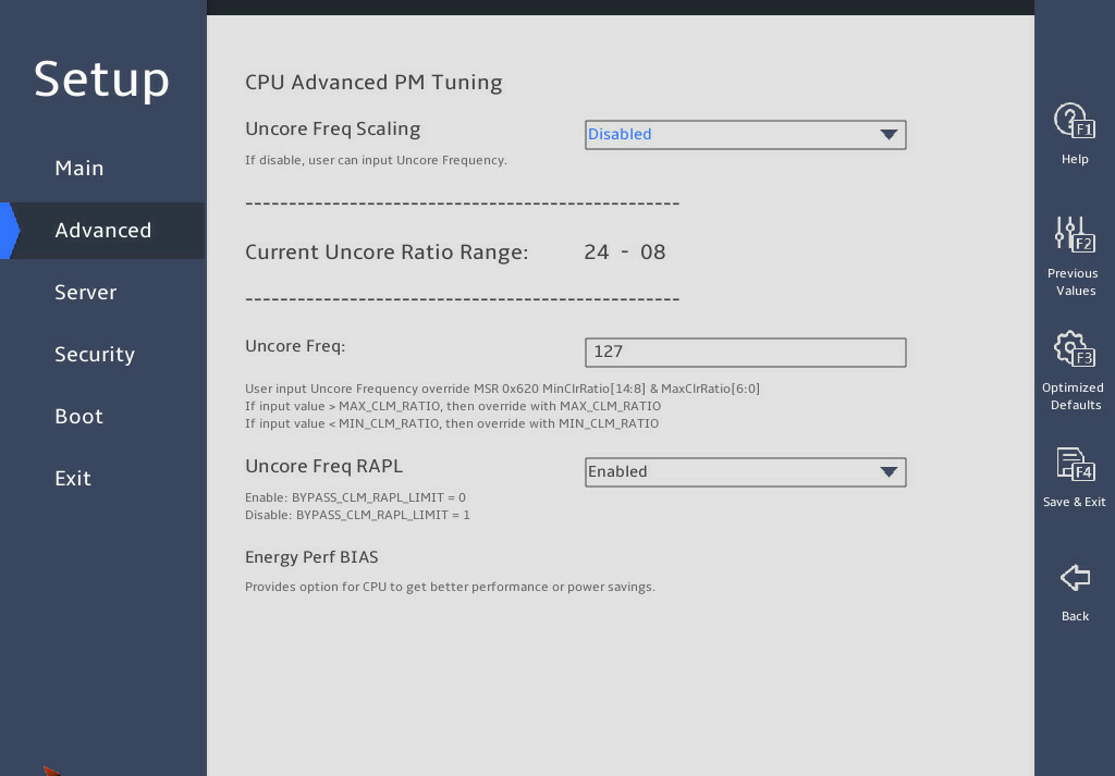
表3-31 Items on the CPU Advanced PM Tuning submenu screen
|
Item |
Description |
Default |
|
Uncore Freq Scaling |
This item is not available for the R6900 G5. Select whether to enable uncore frequency scaling. Options include: · Disabled—Disables uncore frequency scaling. When this feature is disabled, you can set the uncore frequency. · Enabled—Enables uncore frequency scaling. This feature allocates power resources across cores and uncores to maximize the server performance without wasting power. |
Disabled |
|
Current Uncore Ratio Range |
This item is not available for the R6900 G5. Set the current uncore ratio range. This item is available only when Uncore Freq Scaling is set to Disabled. |
N/A |
|
Uncore Freq |
This item is not available for the R6900 G5. Set the uncore frequency. This item is available only when Uncore Freq Scaling is set to Disabled. |
127 |
|
Uncore Freq RAPL |
This item is not available for the R6900 G5. Select whether to enable the uncore frequency run-time average power limit (RAPL). Options include: · Disabled. · Enabled. |
Enabled |
|
Energy and performance bias configuration submenu, on which you can configure the energy and performance policy for the system, as shown in 图3-43. The submenu items are described in 表3-32. |
|
Energy Perf BIAS submenu
图3-43 shows the Energy Perf BIAS submenu screen. The submenu items are described in 表3-32.
图3-43 Energy Perf BIAS submenu screen
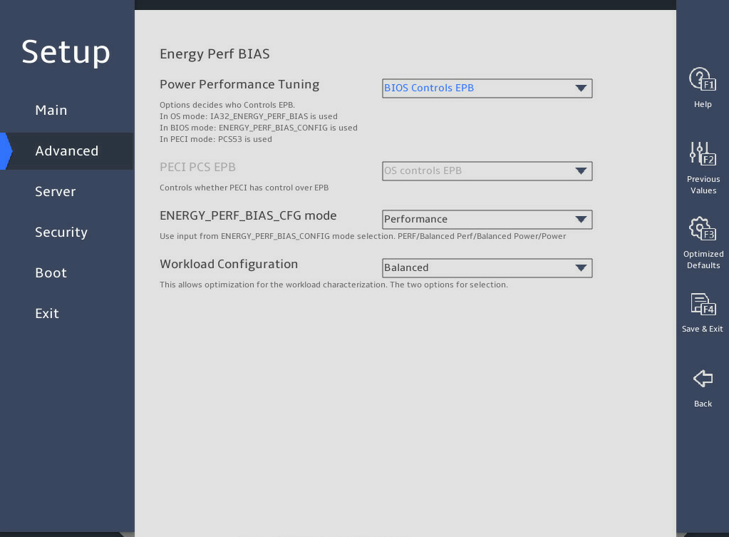
表3-32 Items on the Energy Perf BIAS submenu screen
|
Item |
Description |
Default |
|
Power Performance Tuning |
This item is inaccessible when Hardware P-States is set to Out of Band Mode. Select the method to control energy and performance bias tuning. Options: · OS Controls EPB—This option is not available when Hardware P-States is set to Out of Band Mode or Native Mode with No Legacy Support. · PECI Controls EPB—This option is not available for the R6900 G5. For other servers, this option is the default when Hardware P-States is set to Out of Band Mode. |
BIOS Controls EPB |
|
PECI PCS EPB |
This item is unconfigurable when Hardware P-States is set to Out of Band Mode or Power Performance Tuning is set to BIOS Controls EPB. Select whether to authorize PECI with the control over EPB. Options: · OS controls EPB—Enables the operating system to control EPB. · PECI controls EPB using PCS—Enables PECI to control EPB by using packet config space (PCS). |
OS controls EPB |
|
ENERGY_PERF_BIAS_CFG Mode |
This item is available only when Energy Performance Tuning is set to BIOS Controls EPB. Select an energy and performance bias option. The setting for this option overrides the energy and performance bias configured by the operating system. Options: · Performance—Provides maximum system performance (maximum cooling) at the expense of energy efficiency. · Balanced Performance—Provides optimum performance with good energy efficiency. · Balanced Power—Provides optimum power efficiency with good performance. · Power—Provides maximum power efficiency (maximum power saving) at the expense of system performance. |
Performance |
|
Workload Configuration |
Select the workload option. Options: · Balanced—Balances the performance. · I/O sensitive—Keeps I/O sensitive. |
Balanced |
Memory Power & Thermal Configuration submenu
图3-44 shows the Memory Power & Thermal Configuration submenu screen for the R6900 G5. The submenu items are described in 表3-33.
图3-44 Memory Power & Thermal Configuration submenu screen ( for the R6900 G5)
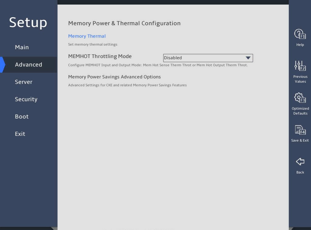
表3-33 Items on the Memory Power & Thermal Configuration submenu screen ( for the R6900 G5)
|
Item |
Description |
Default |
|
Memory Thermal |
Configure memory thermal settings. |
N/A |
|
MEMHOT Throttling Mode |
Configure the MEMHOT I/O settings. Options: · Disabled—Disables the MEMHOT I/O mode. · Output-Only—Enables the output mode only. · Input-Only—Enables the input mode only. · Input and Output Enabled—Enables both the output mode and input mode. |
Disabled |
|
Memory Power Saving Advanced Options |
Set the advanced memory power saving settings. |
N/A |
图3-45 shows the Memory Power & Thermal Configuration submenu screen for the B5700, R4300, R4700, R4900, R5300, and R5500 G5. The submenu items are described in 表3-34.
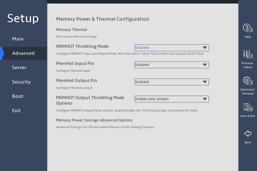
|
Item |
Description |
Default |
|
Memory Thermal |
Configure memory thermal settings. |
N/A |
|
MEMHOT Throttling Mode |
Configure the MEMHOT I/O mode. Options: · Enabled—Enables the MEMHOT I/O mode. · Disabled—Disables the MEMHOT I/O mode. |
Enabled |
|
MemHot Input Pin |
Select Enabled or Disabled to enable or disable the MEMHOT input pin. |
Enabled |
|
MemHot Output Pin |
Select Enabled or Disabled to enable or disable the MEMHOT output pin. |
Enabled |
|
MEMHOT Output Throttling Mode Options |
Set the MEMHOT output throttling mode option. Options: · Disabled—Disables the MEMHOT output throttling mode. · Enabled only tempi—Enables the MEMHOT output throttling mode only for high bit fields. · Enabled only tempi & mid—Enables the MEMHOT output throttling mode only for high and middle bit fields. · Enabled only tempi, mid and low—Enables the MEMHOT output throttling mode for high, middle, and low bit fields |
Enabled only tempi |
|
Memory Power Saving Advanced Options |
Set the advanced memory power saving settings. |
N/A |
图3-46 shows the Memory Thermal submenu screen. The submenu items are described in 表3-35.
图3-46 Memory Thermal submenu screen

表3-35 Items on the Memory Thermal submenu screen
|
Item |
Description |
Default |
|
Throttling Mode |
Set the throttling mode. Options: · Disabled—Disables the throttling mode. · OLTT—Enables OLTT to allow MRC to set a temperature threshold for thermal throttling. · CLTT—Enables CLTT to allow thermal throttling based on the memory TSOD temperature. · CLTT with PECI—Enables CLTT with PECI for thermal throttling. |
CLTT |
|
OFF PKG MEM TO MEMTRIP |
This item is not available for the R6900 G5. Select whether to add the offpkg memtrip to the MEMtrip tree. Options: · Disabled—Ignores the offpkg memtrip. · Enabled—Adds the offpkg memtrip to the memtrip tree. |
Disabled |
图3-47 shows the Memory Power Saving Advanced Options submenu screen. The submenu items are described in 表3-36.
图3-47 Memory Power Saving Advanced Options submenu screen

表3-36 Items on the Memory Power Saving Advanced Options submenu screen
|
Item |
Description |
Default |
|
CKE Throttling |
Set the Clock Enable (CKE) throttling mode. If CKE is disabled, the internal DDR clock is disabled and DDR power consumption decreases. Options: · Auto—Enables the CPU to set the CKE throttling mode automatically. · Manual—Sets the throttling mode manually. |
Auto |
|
CKE Feature |
This item is available only when CKE Throttling is set to Manual. Submenu for configuring the CKE feature. |
N/A |
图3-48 shows the CKE Feature submenu screen. The submenu items are described in 表3-37.
图3-48 CKE Feature submenu screen

表3-37 Items on the CKE Feature submenu screen
|
Item |
Description |
Default |
|
CKE Idle Timer |
Displays the CKE idle timer, in ns. As a best practice, set a value larger than 20. |
20ns |
|
APD |
Select Enabled or Disabled to enable or disable active power down (APD). With APD enabled, the system retains pages opened in DDR, which minimizes power saving performance. |
Disabled |
|
PPD |
Select Enabled or Disabled to enable or disable pre-charged power-down (PPD). This mode is entered if all banks in DDR are pre-charged when de-asserting CKE. Power-saving in this mode is intermediate. |
Enabled |
3.2.2 Platform Configuration submenu
As shown in 图3-49, the Platform Configuration menu contains the submenus described in 表3-38.
图3-49 Platform Configuration menu screen
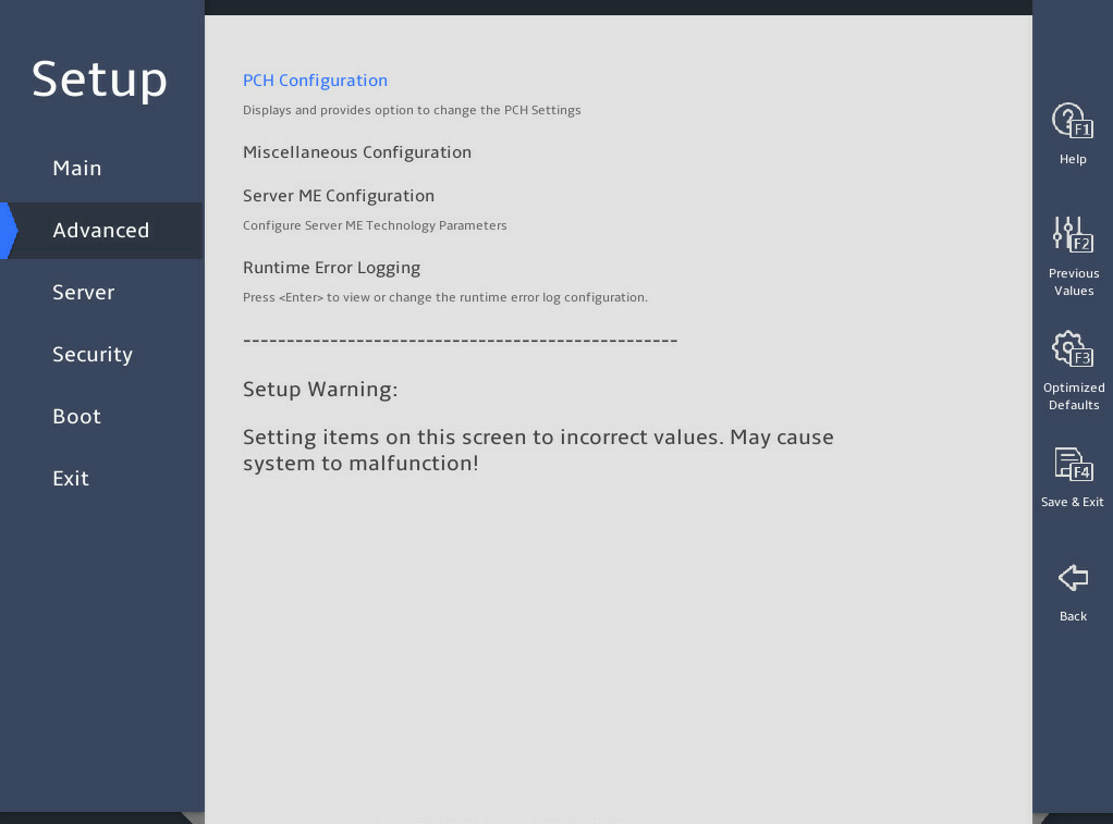
表3-38 Items on the Platform Configuration menu screen
|
Item |
Description |
|
PCH Configuration |
Submenu for configuring the platform controller hub (PCH). |
|
Miscellaneous Configuration |
Submenu for configuring miscellaneous settings, including video display device and debug mode settings. |
|
Server ME Configuration |
Submenu for configuring the server management engine (ME). |
|
Runtime Error Logging |
Submenu for configuring runtime error logging. |
2. PCH Configuration submenu
图3-50 shows the PCH Configuration submenu screen, on which you can configure PCH settings as described in 表3-39.
图3-50 PCH Configuration submenu screen
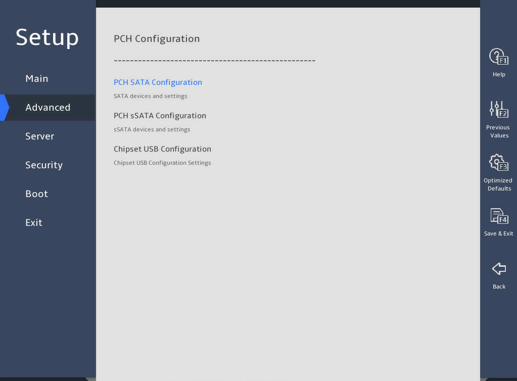
表3-39 Items on the PCH Configuration submenu screen
|
Item |
Description |
|
PCH SATA Configuration |
Submenu for configuring PCH SATA settings, as shown in 图3-51, and 图3-52. The submenu menu items are described in 表3-40. This submenu is not available for the B5700 G5. |
|
PCH sSATA Configuration |
Submenu for configuring PCH sSATA settings, as shown in 图3-53 and 图3-54. |
|
Chipset USB Configuration |
Submenu for configuring USB, as shown in 图3-55. The submenu menu items are described in 表3-43. |
PCH SATA Configuration submenu
图3-51 and 图3-52 show the PCH SATA Configuration submenu screen. The submenu items are described in 表3-40.
图3-51 PCH SATA Configuration submenu screen (1)
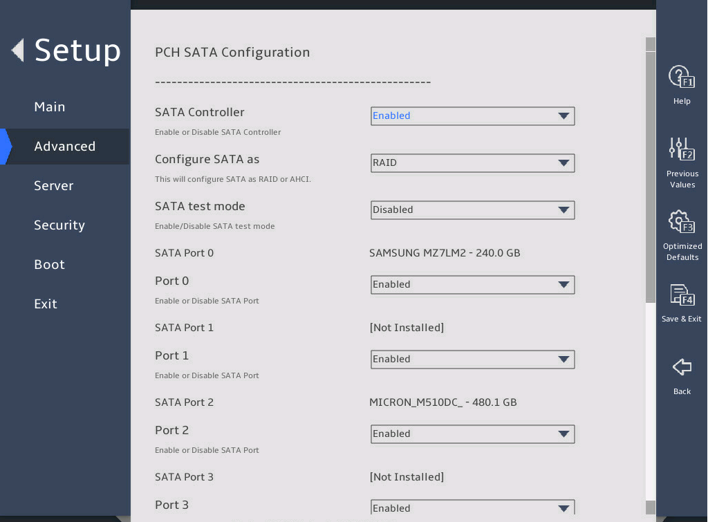
图3-52 PCH SATA Configuration submenu screen (2)
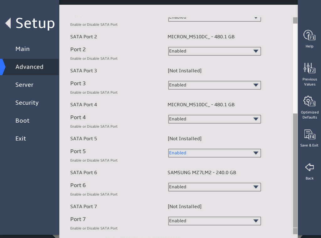
表3-40 Items on the PCH SATA Configuration submenu screen
|
Item |
Description |
Default |
|
SATA Controller |
Select Enabled or Disabled to enable or disable the SATA controller. |
Enabled |
|
Configure SATA As |
Select the operating mode of the SATA controller. Options: · AHCI—Uses the AHCI mode, which allows the drives attached to the SATA ports to be used as SATA disks. This mode supports hot swapping of drives. To use this mode, a SATA driver must be installed. · RAID—Uses the RAID mode, which allows creation of a logical drive from multiple independent physical drives. To configure the embedded RSTe RAID controller, select this option. |
AHCI |
|
SATA Test Mode |
Select Enabled or Disabled to enable or disable SATA test mode. |
Disabled |
|
SATA Port N |
Displays the name and slot number of the drive connected to logic PCH SATA port N. If no drive is connected, Not Installed is displayed. The number of SATA ports varies by server model. Usually there are 0 to 7 ports. |
N/A |
|
Port N |
Select Enabled or Disabled to enable or disable the drive connected to SATA port N. |
Enabled |
PCH sSATA Configuration submenu
图3-53 and 图3-54 show the PCH sSATA Configuration submenu screen. The submenu items are described in 表3-41.
图3-53 PCH sSATA Configuration submenu screen (1)
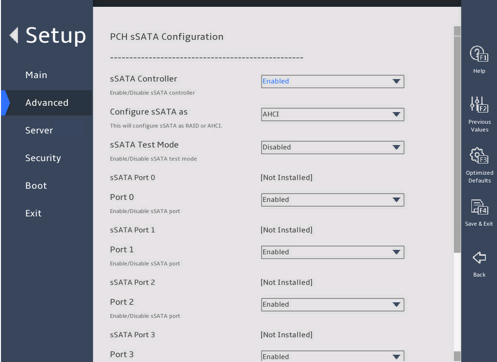
图3-54 PCH sSATA Configuration submenu screen (2)
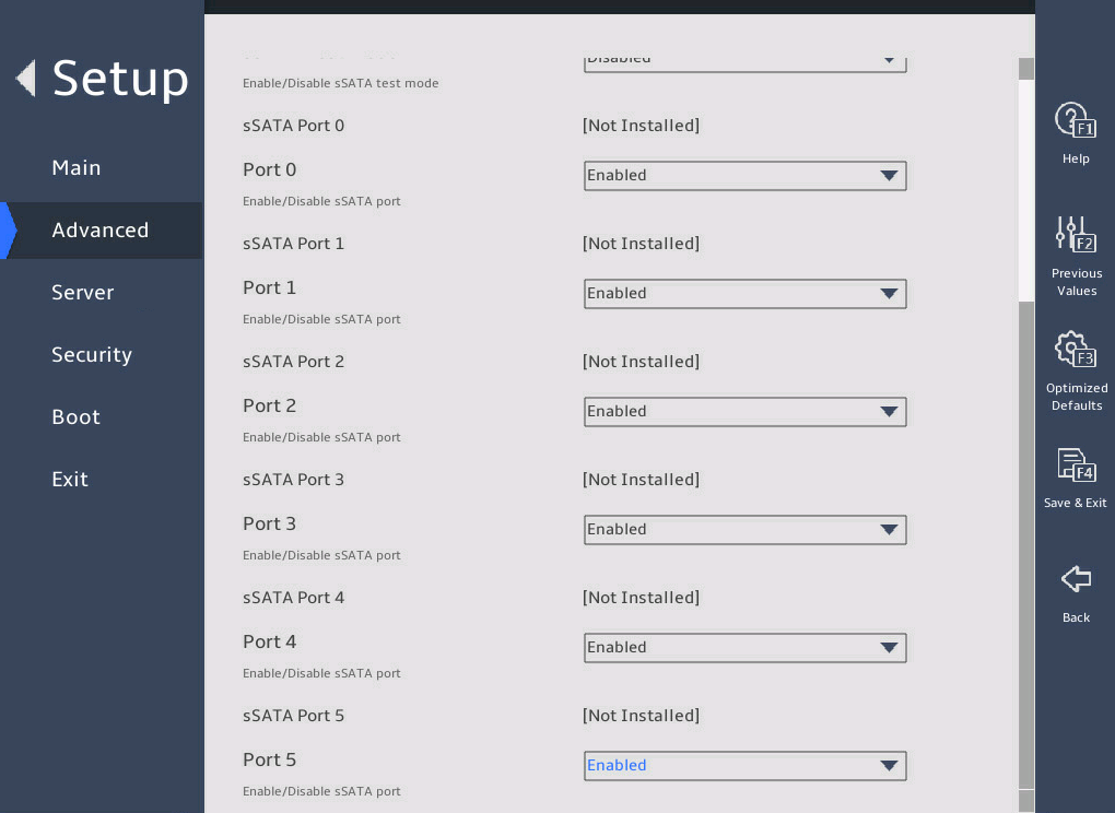
表3-41 Items on the PCH sSATA Configuration submenu screen
|
Item |
Description |
Default |
|
sSATA Controller |
Select Enabled or Disabled to enable or disable the sSATA controller. |
Enabled |
|
Configure sSATA As |
Select the operating mode of the drive controller. Options: · AHCI—Uses the AHCI mode, which allows the drives attached to the SATA ports to be used as SATA disks. This mode supports hot swapping of drives. To use this mode, a SATA driver must be installed. · RAID—Uses the RAID mode, which allows creation of a logical drive from multiple independent physical drives. To configure the embedded RSTe RAID controller, select this option. |
AHCI |
|
sSATA Test Mode |
Select Enabled or Disabled to enable or disable sSATA test mode. |
Disabled |
|
sSATA Port N |
Displays the name and the slot number of the drive connected to logic PCH sSATA port N. If no drive is connected, Not Installed is displayed. The number of sSATA ports varies by server model. For more information, see 表3-42. |
N/A |
|
Port N |
Select Enabled or Disabled to enable or disable the drive connected to sSATA port N. |
Enabled |
表3-42 sSATA output ports available for each server model
|
Server model |
sSATA output ports |
|
R4300 G5 |
Ports 0 through 5 |
|
R4700 G5 |
Ports 0 through 5 |
|
R4900 G5 |
Ports 0 through 5 |
|
R5300 G5 |
Ports 0 to 1 |
|
R5500 G5 Intel |
Ports 0 to 1 |
|
R6900 G5 |
Ports 0 to 1 |
|
B5700 G5 |
Ports 0 through 3 |
Chipset USB Configuration submenu
图3-55 shows the Chipset USB Configuration submenu screen. The submenu items are described in 表3-43.
The number of USB ports and installation locations for USB ports are different for each server model. The Chipset USB Configuration submenu screen varies by server model.
图3-55 Chipset USB Configuration submenu screen
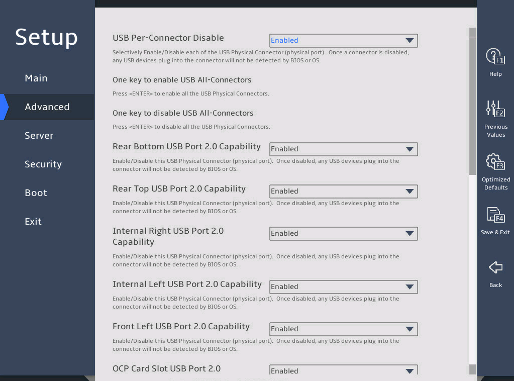
表3-43 Items on the Chipset USB Configuration submenu screen
|
Parameter |
Description |
Default |
|
USB Per-Connector Disable |
Enable or disable independent control of individual USB connectors on the system board. If the USB port is disabled, a USB device inserted into this port cannot be detected by the BIOS or the operating system. Options: · Enabled—You can control USB connectors on a per-connector basis. · Disabled—You cannot control USB connectors on a per-connector basis. |
Disabled |
|
One key to enable USB All-Connectors |
Enable all USB connectors. This item is available only when USB Per-Connector Disable is set to Enabled. |
N/A |
|
One key to disable USB All-Connectors |
Disable all USB connectors. This item is available only when USB Per-Connector Disable is set to Enabled. |
N/A |
3. Miscellaneous Configuration submenu
图3-56 shows the Miscellaneous Configuration submenu screen, on which you can configure features described in 表3-44.
图3-56 Miscellaneous Configuration submenu screen

表3-44 Items on the Miscellaneous Configuration submenu screen
|
Item |
Description |
Default |
|
Active Video |
Select a monitor to display videos. Options: · Auto—Enables the server to automatically select a monitor to display videos. · Onboard Device—Uses the monitor connected to the onboard VGA connector to display videos. · PCIe Device—Uses the monitor connected to the GPU module in the PCIe slot to display videos. NOTE: In legacy boot mode, the server cannot display the BIOS menus on the monitor connected to the GPU module or VGA connector if the Onboard Device or PCIe Device option is selected, respectively. |
Onboard Device |
4. Server ME Configuration submenu
图3-57 and 图3-58 show the Server ME Configuration submenu screen, on which you can view server management engine information described in 表3-45.
图3-57 Server ME Configuration submenu screen (1)
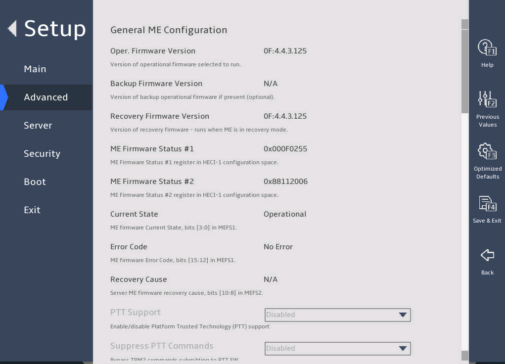
图3-58 Server ME Configuration submenu screen (2)
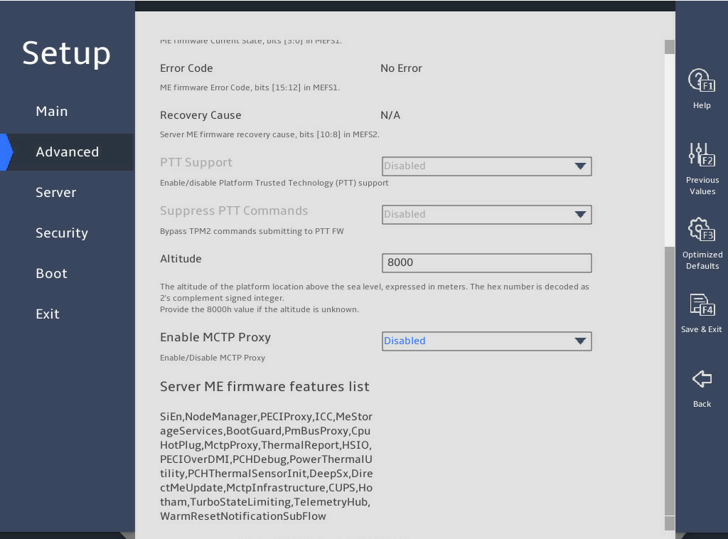
表3-45 Items on the Server ME Configuration submenu screen
|
Item |
Description |
Default |
|
Oper. Firmware Version |
Displays the active firmware version. |
N/A |
|
Backup Firmware Version |
Displays the backup firmware version. |
N/A |
|
Recovery Firmware Version |
Displays the recovery firmware version. |
N/A |
|
ME Firmware Status #1 |
Displays ME firmware status #1. |
N/A |
|
ME Firmware Status #2 |
Displays ME firmware status #2. |
N/A |
|
Current State |
Displays the current ME state. |
N/A |
|
Error Code |
Displays the error code. |
N/A |
|
Recovery Cause |
Displays the reason for recovery. |
N/A |
|
PTT Support |
Displays support for the Platform Trusted Technology (PTT). |
N/A |
|
Suppress PTT Commands |
Displays the suppressed PTT commands. |
N/A |
|
Altitude |
Set the altitude at which the server is located, a hexadecimal value in meters. The default is 8000 meters (or 26246.72 ft). |
8000 |
|
Enable MCTP Proxy |
Select Enabled or Disabled to enable or disable MCTP proxy. |
· B5700 G5: Enabled · Other servers: Disabled |
5. Runtime Error Logging submenu
图3-59 and 图3-60 show the Runtime Error Logging submenu screen, on which you can configure the runtime error logging as described in 表3-46.
图3-59 Runtime Error Logging submenu screen (1)
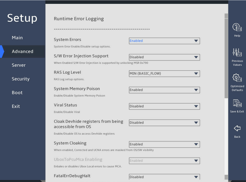
图3-60 Runtime Error Logging submenu screen (2)
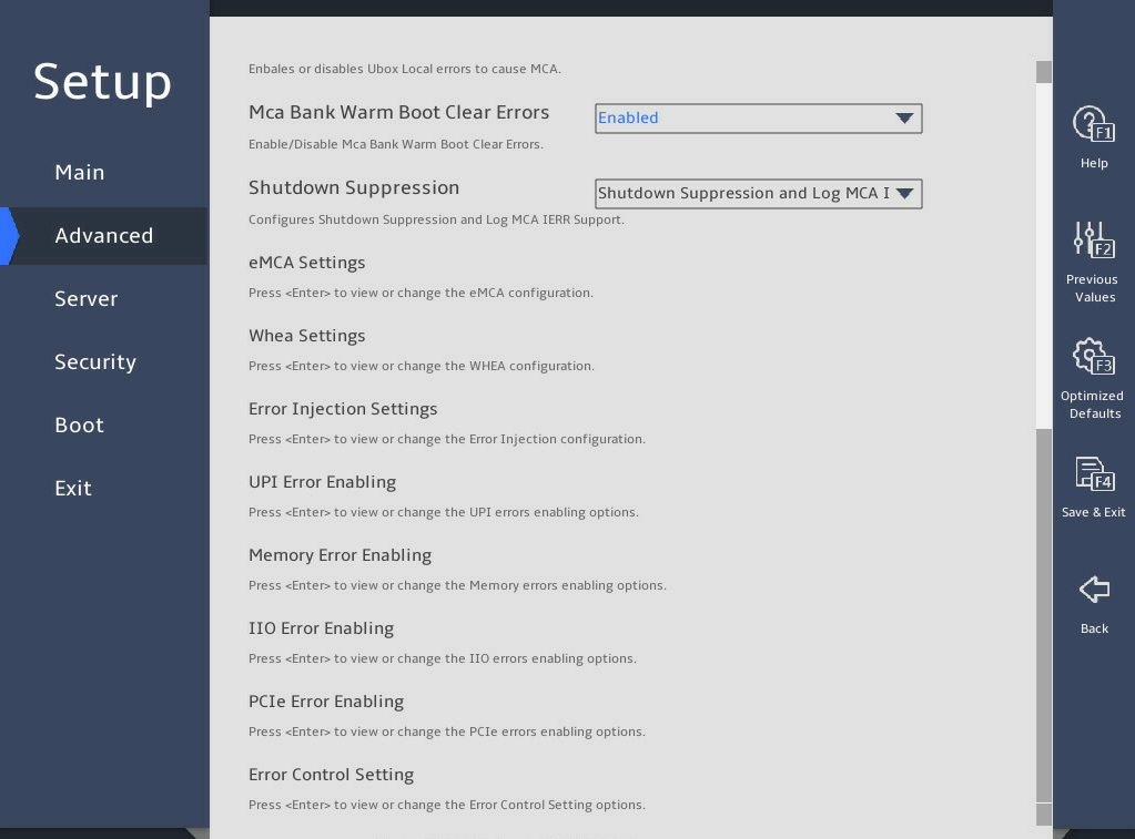
表3-46 Items on the Runtime Error Logging submenu screen
|
Item |
Description |
Default |
|
System Errors |
This item controls system error logging, which enables the server to correct system errors automatically and report uncorrectable errors to HDM and the operating system. Select Enabled or Disabled to enable or disable system error logging. |
Enabled |
|
S/W Error Injection Support |
This item is available only when System Errors is set to Enabled. Software error injection tests system performance by injecting software errors. To test system performance, select Enabled. |
Disabled |
|
RAS Log Level |
Display the RAS log level. Options: · None. · MIN (BASIC_FLOW). · MID (BASIC_FLOW, FUNC_FLOW). · MAX (BASIC_FLOW, FUNC_FLOW, REG). |
MIN (BASIC_FLOW) |
|
System Memory Poison |
This item is available only when System Errors is set to Enabled. Select Enabled or Disabled to enable or disable system memory poison. To report event logs to HDM when uncorrectable memory errors are injected, you must set both System Memory Poison and Viral Status to Disabled. |
Enabled |
|
Viral Status |
This item is available only when System Errors is set to Enabled. Select Enabled or Disabled to enable or disable detection of memory-resident viruses. To report event logs to HDM when uncorrectable memory errors are injected, you must set both System Memory Poison and Viral Status to Disabled. |
Disabled |
|
Clear Viral Status |
This item is unavailable when Viral Status or System Errors is set to Disabled. Select Enabled or Disabled to enable or disable the clear viral status feature. |
Disabled |
|
Cloak Devhide registers from being accessible from OS |
This item is available only for the R6900 G5. Select Enabled or Disabled to enable or disable access to the Cloak Devhide register from OS. |
Disabled |
|
System Cloaking |
This item is available only when System Errors is set to Enabled. System cloaking enables the operating system and software to block corrected errors and uncorrected no action required (UCNA) errors. Select Enabled or Disabled to enable or disable system cloaking. |
Enabled |
|
UboxToPcuMca Enabling |
This item is available only when System Errors is set to Enabled. This item is not configurable. Select Enabled or Disabled to enable or disable the server to report Ubox errors to Machine Check Architecture (MCA). |
Enabled |
|
FatalErrDebugHalt |
This item is available only when System Errors is set to Enabled, and this feature is applicable only to McBank fatal error debugging. Select Enabled or Disabled to enable or disable halting fatal error debugging. Enable this feature only in conjunction with Intel® Technology Provider (ITP) because a thread will halt in fatal error flow. |
Disabled |
|
Mca Bank Warm Boot Clear Errors |
Select Enabled or Disabled to set whether to clear error information during MCA hot reboot. |
Enabled |
|
Shutdown Suppression |
This item is not available for the R6900 G5. Set the shutdown suppression and log MCA IERR support. Options: · Disabled—Disables shutdown suppression. · Shutdown Sippression and Log MCA IERR—Enables shutdown suppression and logs MCA IERR errors. · Shutdown Log MCA IERR—Disables shutdown suppression and logs MCA IERR errors. |
Shutdown Sippression and Log MCA IERR |
|
eMCA Settings |
This item is available only when System Errors is set to Enabled. Access the submenu for configuring the Enhanced Machine Check Architecture (eMCA), as shown in 图3-61 and 图3-62. The submenu items are described in 表3-47. |
N/A |
|
Whea Settings |
This item is available only when System Errors is set to Enabled. Access the submenu for configuring the Windows Hardware Error Architecture (WHEA), as shown in 图3-63. The submenu items are described in 表3-48. |
N/A |
|
Error Injection Settings |
This item is available only when System Errors is set to Enabled. Access the submenu for configuring error injection settings, as shown in 图3-64. The submenu items are described in 表3-49. |
N/A |
|
UPI Error Enabling |
This item is configurable only when the processors support the Advanced RAS feature. This item is available only when System Errors is set to Enabled. Access the submenu for configuring UltraPath Interconnect (UPI) error reporting, as shown in 图3-65. The submenu items are described in 表3-50. |
N/A |
|
Memory Error Enabling |
This item is available only when System Errors is set to Enabled. Access the submenu for configuring memory error reporting, as shown in 图3-66 and 图3-67. The submenu items are described in 表3-51. |
N/A |
|
IIO Error Enabling |
This item is available only when System Errors is set to Enabled. Access the submenu for configuring Integrated I/O module (IIO) error reporting, as shown in 图3-68, 图3-69, 图3-70, and 图3-71. The submenu items are described in 表3-52. |
N/A |
|
PCIe Error Enabling |
This item is available only when System Errors is set to Enabled. Access the submenu for configuring PCIe error reporting, as shown in 图3-72, 图3-73, and 图3-74. The submenu items are described in 表3-53. |
N/A |
|
Error Control Setting |
This item is available only when System Errors is set to Enabled. Access the submenu for configuring error control settings, as shown in 图3-75. The submenu items are described in 表3-54. This submenu is not available for the R6900 G5. |
N/A |
eMCA Settings submenu
图3-61 and 图3-62 show the eMCA Settings submenu screen. The submenu items are described in 表3-47.
图3-61 eMCA Settings submenu screen (1)
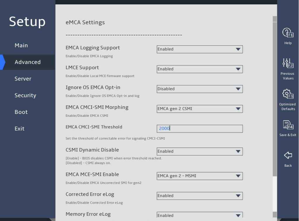
图3-62 eMCA Settings submenu screen (2)
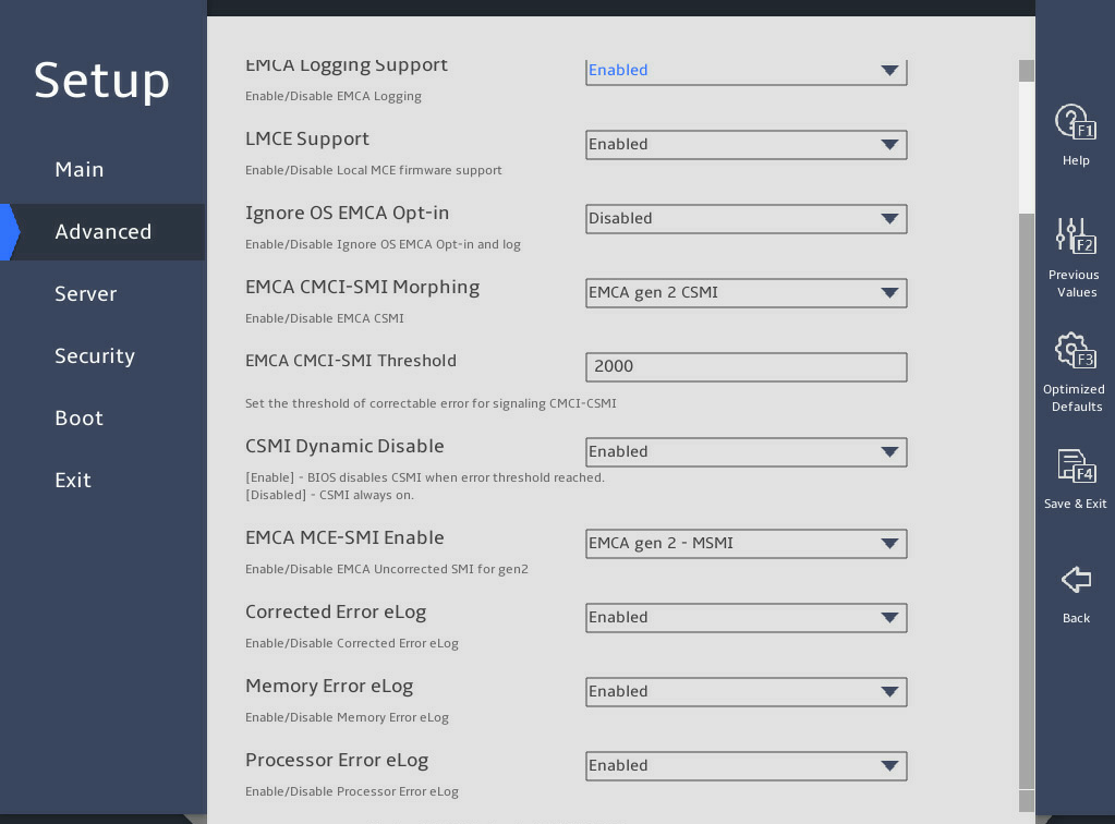
表3-47 Items on the eMCA Settings submenu screen
|
Item |
Description |
Default |
|
EMCA Logging Support |
Select Enabled or Disabled to enable or disable eMCA logging. eMCA logging provides MAC error reports for the server. |
Enabled |
|
LMCE Support |
Select Enabled or Disabled to enable or disable local machine check exceptions (LMCE) support. This feature enables the system to report uncorrectable errors of the Software Recoverable Action Required (SRAR) type only to affected logical processors. |
Enabled |
|
Ignore OS EMCA Opt-in |
This item is available only when EMCA Logging Support is set to Enabled. Select Enabled or Disabled to enable or disable the ignore OS EMCA opt-in feature. |
Disabled |
|
EMCA CMCI-SMI Morphing |
This item is available only when EMCA Logging Support is set to Enabled. When EMCA CMCI-SMI morphing is enabled: · An SMI is triggered each time a correctable error occurs. · If the number of correctable errors on the MCBank exceeds the upper limit, an SMI is triggered but a Corrected Machine Check Interrupt (CMCI) is not. Options: · EMCA gen 2 CSMI—Enables EMCA CMCI-SMI morphing in EMCA gen 2 CSMI mode. · Disabled—Disables EMCA CMCI-SMI morphing. |
EMCA gen 2 CSMI |
|
EMCA CMCI-SMI Threshold |
Set the CMCI-SMI threshold for eMCA reported correctable errors. |
2000 |
|
CSMI Dynamic Disable |
Set the CSMI dynamic settings. Options: · Enabled—Enables the system to disable CSMI when the number of errors reaches the threshold. · Disabled—Forbids the system from disabling CSMI. With this feature disabled, CSMI is always enabled. |
Enabled |
|
EMCA MCE-SMI Enable |
This item is available only when EMCA Logging Support is set to Enabled. Options: · EMCA gen 2 – MSMI—Enables EMCA MCE-SMI in EMCA gen 2 MSMI mode. · Disabled—Disables EMCA MCE-SMI. |
EMCA gen 2 – MSMI |
|
Corrected Error eLog |
This item is available only when EMCA Logging Support is set to Enabled. Select Enabled or Disabled to enable or disable eMCA correctable error logging. |
Enabled |
|
Memory Error eLog |
This item is available only when EMCA Logging Support is set to Enabled. Select Enabled or Disabled to enable or disable eMCA memory error logging. |
Enabled |
|
Processor Error eLog |
This item is available only when EMCA Logging Support is set to Enabled. Select Enabled or Disabled to enable or disable eMCA processor error logging. |
Enabled |
|
Ubox Error Mask |
This item is available only for the R6900 G5. This item is available only when EMCA Logging Support is set to Enabled. Select Enabled or Disabled to enable or disable SMI used for Ubox error trigger. |
Disabled |
Whea Settings submenu
图3-63 shows the Whea Settings submenu screen. The submenu items are described in 表3-48.
图3-63 Whea Settings submenu screen
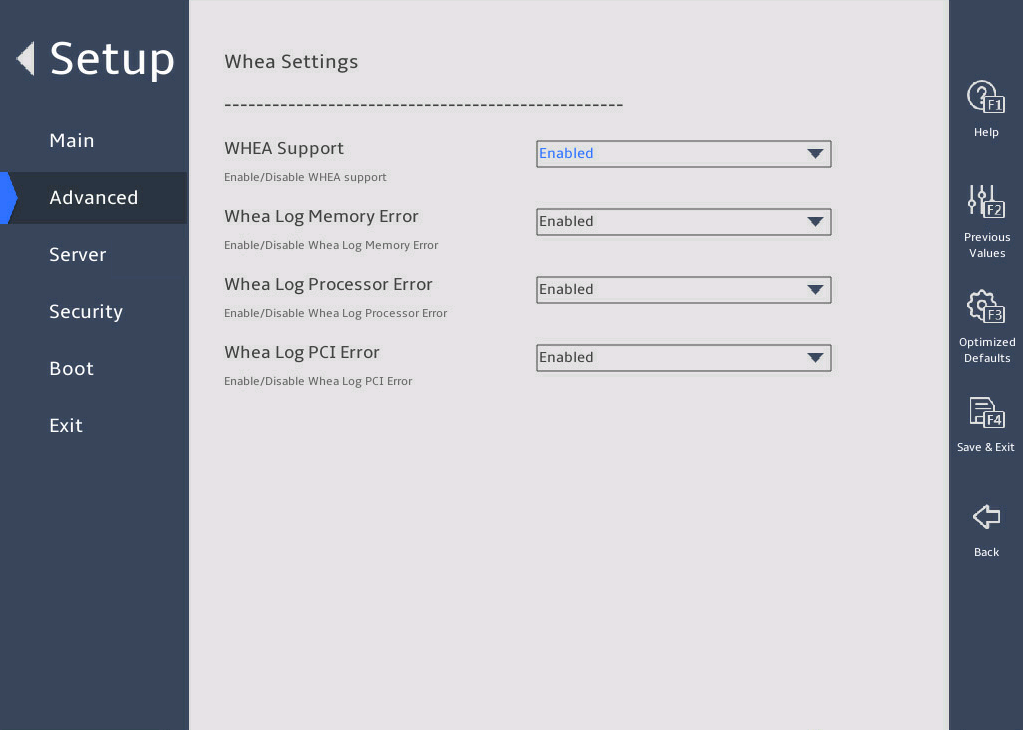
表3-48 Items on the Whea Settings submenu screen
|
Item |
Description |
Default |
|
WHEA Support |
Select Enabled or Disabled to enable or disable WHEA. WHEA provides hardware error reports for the server. |
Enabled |
|
Whea Log Memory Error |
Select Enabled or Disabled to enable or disable WHEA memory error logging. |
Enabled |
|
Whea Log Processor Error |
Select Enabled or Disabled to enable or disable WHEA processor error logging. |
Enabled |
|
Whea Log PCI Error |
Select Enabled or Disabled to enable or disable WHEA PCI error logging. |
Enabled |
Error Injection Settings submenu
图3-64 shows the Error Injection Settings submenu screen. The submenu items are described in 表3-49.
图3-64 Error Injection Settings submenu screen
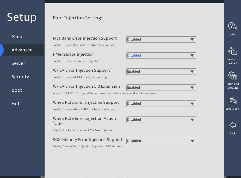
表3-49 Items on the Error Injection Settings submenu screen
|
Item |
Description |
Default |
|
Mca Bank Error Injection Support |
Availability of this item depends on the processor model. This item is available only when System Errors is set to Enabled. Select Enabled or Disabled to enable or disable MCA bank error injection. If MCA bank error injection is enabled, the write function of the register into which errors are injected is enabled. |
Disabled |
|
PMem Error Injection |
Select Enabled or Disabled to enable or disable the PMem error injection. |
Disabled |
|
WHEA Error Injection Support |
Select Enabled or Disabled to enable or disable WHEA error injection. |
Disabled |
|
WHEA Error Injection 5.0 Extension |
This item is available only when WHEA Error Injection Support is set to Enabled. Select Enabled or Disabled to enable or disable support for WHEA error injection 5.0 extension. |
Enabled |
|
Whea PCIE Error Injection Support |
This item is available only when WHEA Error Injection Support is set to Enabled. Select Enabled or Disabled to enable or disable WHEA PCIe error injection. |
Disabled |
|
Whea PCIe Error Injection Action Table |
This item is available only when WHEA Error Injection Support is set to Enabled. Select Enabled or Disabled to enable or disable WHEA PCIe error injection action table. |
Disabled |
|
SGX Memory Error Inject Support |
This item is not available for the R6900 G5. This item is available only when WHEA Error Injection Support is set to Enabled. Select Enabled or Disabled to enable or disable SGX memory error injection. |
Disabled |
UPI Error Enabling submenu
图3-65 shows the UPI Error Enabling submenu screen. The submenu items are described in 表3-50.
图3-65 UPI Error Enabling submenu screen
表3-50 Items on the UPI Error Enabling submenu screen
|
Item |
Description |
Default |
|
SMI UPI Lane Failover |
Select Enabled or Disabled to enable or disable triggering an SMI upon a UPI lane failover. |
Disabled |
Memory Error Enabling submenu
图3-66 and 图3-67 show the Memory Error Enabling submenu screen. The submenu items are described in 表3-51.
图3-66 Memory Error Enabling submenu screen (1)

图3-67 Memory Error Enabling submenu screen (2)
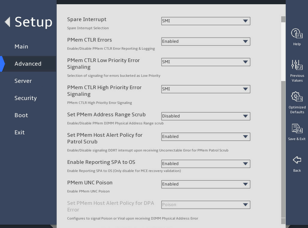
表3-51 Items on the Memory Error Enabling submenu screen
|
Item |
Description |
Default |
|
Memory Error |
Select Enabled or Disabled to enable or disable memory error reporting. |
Enabled |
|
Memory Corrected Error |
This item is available only when Memory Corrected Error is set to Enabled. Select Enabled or Disabled to enable or disable correctable memory error reporting. |
Enabled |
|
Spare Interrupt |
This item is available only when Memory Corrected Error is set to Enabled. Select the type of the spare interrupt to generate upon detection of a memory error. Options: · Disabled—Disables spare interrupt generation. · SMI—Generates an SMI interrupt. · Error Pin—Generates an error pin interrupt. · CMCI—Generates a CMCI interrupt. |
SMI |
|
Memory CE Storm Threshold |
Set the memory correctable error storm threshold. Options: · Disabled. · 120. · 60. · 240. · 1200. |
Disabled |
|
Memory CE Accumulation Threshold |
Set the memory correctable error accumulation threshold. Options: · Disabled. · 1200. · 1. · 500. · 1000. · 2000. · 5000. · 10000. |
Disabled |
|
PMem CTLR Errors |
This item is available only when Memory Corrected Error is set to Enabled. Select Enabled or Disabled to enable or disable NVMCTLR error logging and reporting. |
Enabled |
|
PMem CTLR Low Priority Error Signaling |
This item is available only when Memory Corrected Error is set to Enabled. Set NVMCTLR low priority error signaling. Options: · Disabled—Disables reporting of NVMCTLR low priority errors. · SMI—Uses SMI interrupts to send NVMCTLR low priority error signals. · ERRO# Pin—Uses ERRO# Pin to send NVMCTLR low priority error signals. |
SMI |
|
PMem CTLR High Priority Error Signaling |
This item is available only when Memory Corrected Error is set to Enabled. Set NVMCTLR high priority error signaling configuration. Options: · Disabled—Disables reporting of NVMCTLR high priority errors. · SMI—Uses SMI interrupts to send NVMCTLR high priority error signals. · ERRO# Pin—Uses ERRO# Pin to send NVMCTLR high priority error signals. |
SMI |
|
Set PMem Address Range Scrub |
This item is available only when Memory Corrected Error is set to Enabled. Select Enabled or Disabled to enable or disable NGN DIMM physical address range scrubbing. |
Disabled |
|
Set PMem Host Alert Policy for Patrol Scrub |
This item is configurable only when the processors support the Advanced RAS feature. This item is available only when Memory Corrected Error is set to Enabled. Select Enabled or Disabled to enable or disable the patrol scrubbing error alert policy. With the policy enabled, the system triggers DDRT interrupts based on uncorrectable errors detected by NGN patrol scrubbing. |
Enabled |
|
Enable Reporting SPA to OS |
This item is available only when Memory Corrected Error is set to Enabled. Select Enabled or Disabled to enable or disable system physical address (SPA) reporting to the operating system. If the reporting is enabled, the MCE recovery threshold is disabled. |
Enabled |
|
PMem UNC Poison |
Select whether to enable the poison mode for PMem. Options: · Enabled—When an uncorrectable error is detected in an PMem, the memory marks the abnormal data as poison and then continues to transmit the data. · Disabled—When an uncorrectable error is detected in a PMem, the memory directly reports the error. |
Enabled |
|
Set PMem Host Alert Policy for DPA Error |
Set the PMem memory DIMM physical address (DPA) error system alarm policy. Options: · Poison—Poison mode. · Viral—Virus mode. |
Poison |
IIO Error Enabling submenu
图3-68, 图3-69, 图3-70, and 图3-71 show the IIO Error Enabling submenu screen. The submenu items are described in 表3-52.
图3-68 IIO Error Enabling submenu screen (1)
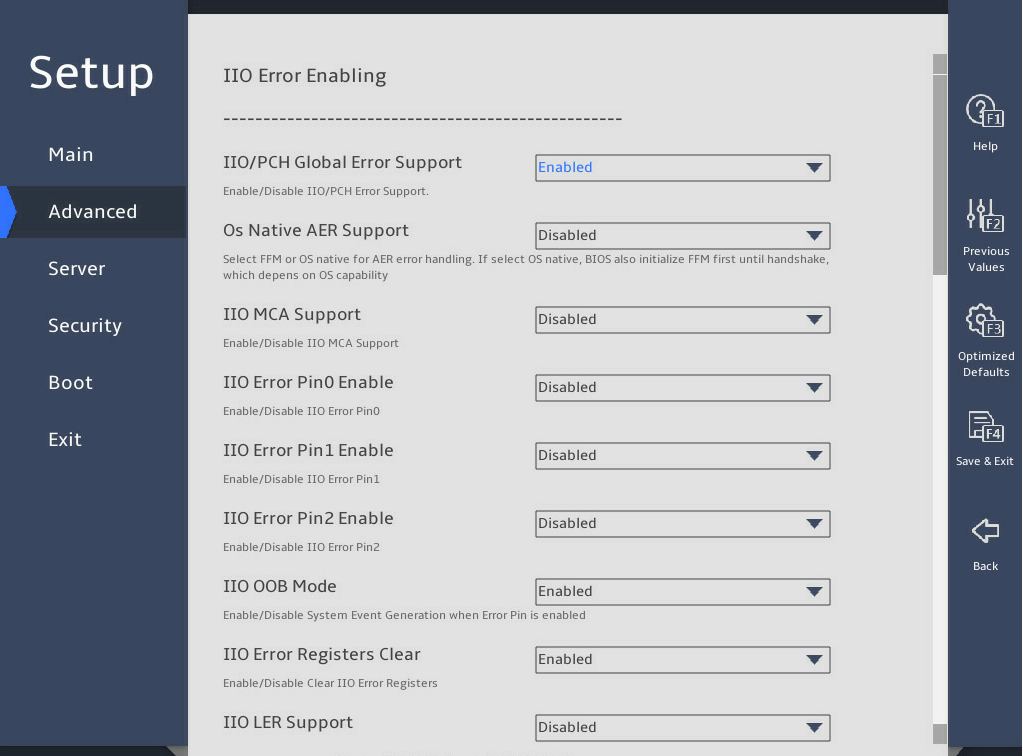
图3-69 IIO Error Enabling submenu screen (2)
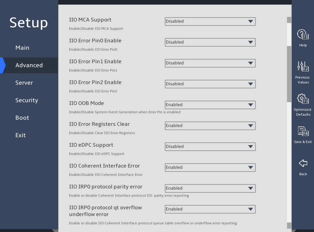
图3-70 IIO Error Enabling submenu screen (3)
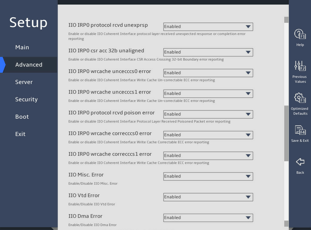
图3-71 IIO Error Enabling submenu screen (4)
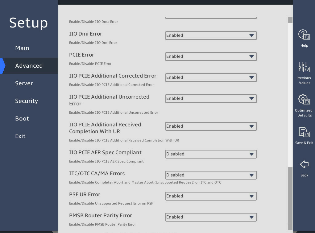
表3-52 Items on the IIO Error Enable submenu screen
|
Item |
Description |
Default |
|
IIO/PCH Global Error Support |
Select Enabled or Disabled to enable or disable IIO/PCH global error reporting. |
Enabled |
|
Os Native AER Support |
Select Enabled or Disabled to enable or disable the AER feature on the OS. |
Disabled |
|
IIO MCA Support |
Select Enabled or Disabled to enable or disable IIO MCA support. |
Disabled |
|
Clear PCC for IIO Non-Fatal Error |
This item is available only when IIO MCA Support is set to Enabled. Select Enabled or Disabled to set whether to clear the PCC register if an IIO non-fatal error occurs. |
Disabled |
|
IIO Error Pin0 Enable |
This item is available only when IIO MCA Support is set to Disabled. Select Enabled or Disabled to enable or disable IIO Error Pin programming. |
Disabled |
|
IIO OOB Mode |
Select Enabled or Disabled to set whether to generate system events when ERROR Pin is enabled. |
Enabled |
|
IIO Error Registers Clear |
Select Enabled or Disabled to enable or disable clearing IIO error registers. |
Enabled |
|
IIO eDPC Support |
This item is not available for the R6900 G5. This item is configurable only when the processors support the Advanced RAS feature. Set the IIO eDPC support. Options: · Disabled—Disables IIO eDPC support. · On Fatal Error—Enables IIO eDPC support when a fatal error occurs. · On Fatal and Non-Fatal Errors—Enables IIO eDPC support when a fatal or non-fatal error occurs. |
Disabled |
|
IIO eDPC Interrupt |
This item is not available for the R6900 G5. This item is configurable only when IIO eDPC Support is not set to Disabled. Select Enabled or Disabled to enable or disable IIO eDPC interrupt. |
Enabled |
|
IIO eDPC ERR_COR Message |
This item is not available for the R6900 G5. This item is configurable only when IIO eDPC Support is not set to Disabled. Select Enabled or Disabled to enable or disable the use of IIO eDPC error COR messages. |
Enabled |
|
IIO LER Support |
This item is available only for the R6900 G5. This item is configurable only when the processors support the Advanced RAS feature. Select Enabled or Disabled to enable or disable IIO live error recovery. |
Disabled |
|
IIO Coherent Interface Error |
Select Enabled or Disabled to enable or disable IIO coherent interface error detection. |
Enabled |
|
IIO IRP0 protocol parity error |
This item is unconfigurable when IIO Coherent Interface Error is set to Disabled. Select Enabled or Disabled to enable or disable IIO IRP0 protocol parity error detection. |
Enabled |
|
IIO IRP0 protocol qt overflow underflow error |
This item is unconfigurable when IIO Coherent Interface Error is set to Disabled. Select Enabled or Disabled to enable or disable the IIO coherent interface protocol layer queue table overflow or underflow error reporting. |
Enabled |
|
IIO IRP0 protocol rcvd unexprsp |
This item is unconfigurable when IIO Coherent Interface Error is set to Disabled. Select Enabled or Disabled to enable or disable error detection on poisoned packets received at the IIO coherent interface protocol layer. |
Enabled |
|
IIO IRP0 csr acc 32b unaligned |
This item is unconfigurable when IIO Coherent Interface Error is set to Disabled. Select Enabled or Disabled to enable or disable reporting of 32-bit boundary crossing errors for IIO coherent interface CSR access. |
Enabled |
|
IIO IRP0 wrcache uncecccs0 error |
This item is unconfigurable when IIO Coherent Interface Error is set to Disabled. Select Enabled or Disabled to enable or disable reporting of IIO coherent interface write cache uncorrectable ECC errors. |
Enabled |
|
IIO IRP0 wrcache uncecccs1 error |
This item is unconfigurable when IIO Coherent Interface Error is set to Disabled. Select Enabled or Disabled to enable or disable reporting of IIO coherent interface write cache uncorrectable ECC errors. |
Enabled |
|
IIO IRP0 protocol rcvd poison error |
This item is unconfigurable when IIO Coherent Interface Error is set to Disabled. Select Enabled or Disabled to enable or disable reporting of poisoned packet errors received at the IIO coherent interface protocol layer. |
Enabled |
|
IIO IRP0 wrcache correcccs0 error |
This item is unconfigurable when IIO Coherent Interface Error is set to Disabled. Select Enabled or Disabled to enable or disable reporting of IIO coherent interface write cache correctable ECC errors. |
Enabled |
|
IIO IRP0 wrcache correcccs1 error |
This item is unconfigurable when IIO Coherent Interface Error is set to Disabled. Select Enabled or Disabled to enable or disable reporting of IIO coherent interface write cache correctable ECC errors. |
Enabled |
|
IIO Misc. Error |
Select Enabled or Disabled to enable or disable miscellaneous IIO error detection. |
Enabled |
|
IIO Vtd Error |
Select Enabled or Disabled to enable or disable IIO Vtd error detection. |
Enabled |
|
IIO Dma Error |
Select Enabled or Disabled to enable or disable IIO DMA error detection. |
Enabled |
|
IIO Dmi Error |
Select Enabled or Disabled to enable or disable IIO DMI error detection. |
Disabled |
|
PCIE Error |
Select Enabled or Disabled to enable or disable PCIe error detection. |
Enabled |
|
IIO PCIE Additional Corrected error |
Select Enabled or Disabled to enable or disable IIO PCIe additional correctable error detection. |
Enabled |
|
IIO PCIE Additional Uncorrected error |
Select Enabled or Disabled to enable or disable IIO PCIe additional uncorrectable error detection. |
Enabled |
|
IIO PCIE Additional Received Completion with UR |
Select Enabled or Disabled to enable or disable IIO PCIe additional received completion with UR. |
Disabled |
|
IIO PCIe AER Spec Compliant |
Select Enabled or Disabled to enable or disable IIO PCIe Advanced Error Reporting (AER) specification compliance checking. If this feature is enabled, poisoned errors are recorded as fatal errors. If this feature is disabled, poisoned errors are recorded as non-fatal errors. |
Disabled |
|
ITC/OTC CA/MA Errors |
Select Enabled or Disabled to enable or disable complete abort and master abort errors on ITC and OTC. |
Disabled |
|
PSF UR Error |
Select Enabled or Disabled to enable or disable unsupported request errors on PSF. |
Enabled |
|
PMSB Router Parity Error |
Select Enabled or Disabled to enable or disable PMSB router parity errors. |
Enabled |
PCIe Error Enabling submenu
图3-72, 图3-73, and 图3-74 show the PCIe Error Enabling submenu screen. The submenu items are described in 表3-53.
图3-72 PCIe Error Enabling submenu screen (1)
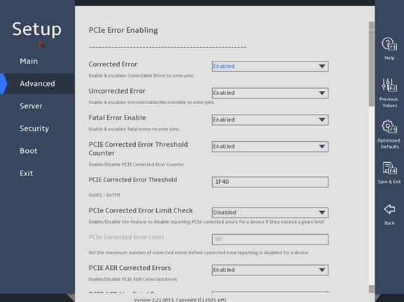
图3-73 PCIe Error Enabling submenu screen (2)
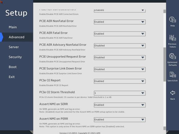
图3-74 PCIe Error Enabling submenu screen (3)
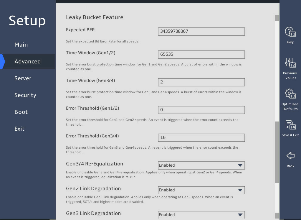
表3-53 Items on the PCIe Error Enabling submenu screen
|
Items |
Description |
Default |
|
Corrected Error |
Select Enabled or Disabled to enable or disable PCIe correctable error detection. |
Enabled |
|
Uncorrected Error |
Select Enabled or Disabled to enable or disable PCIe uncorrectable error detection. |
Enabled |
|
Fatal Error Enable |
Select Enabled or Disabled to enable or disable PCIe fatal error detection. |
Enabled |
|
PCIe Corrected Error Threshold Counter |
Select Enabled or Disabled to enable or disable the PCIe correctable error threshold counter. |
· R6900 G5: Disabled · Other servers: Enabled |
|
PCIE Correctable Error Threshold |
This item is configurable only when PCIe Corrected Error Threshold Counter is set to Enabled. Set the PCIe correctable error threshold. |
· R6900 G5: 1 · Other servers: 0x1F40 (8000) |
|
PCIe Corrected Error Limit Check |
Select Enabled or Disabled to enable or disable the limit on PCIe correctable errors. |
Disabled |
|
PCIe Corrected Error Limit |
This item is configurable only when PCIe Corrected Error Limit Check is set to Enabled. Set the maximum number of PCIe correctable errors that can be reported. Value range: 0 to 4294967295. |
80 |
|
PCIE AER Corrected Errors |
Select Enabled or Disabled to enable or disable PCIe AER correctable error detection. |
Enabled |
|
PCIE AER NonFatal Error |
Select Enabled or Disabled to enable or disable PCIe AER non-fatal error detection. |
Enabled |
|
PCIE AER Fatal Error |
Select Enabled or Disabled to enable or disable PCIe AER fatal error detection. |
Enabled |
|
PCIE AER Advisory Nonfatal Error |
Select Enabled or Disabled to enable or disable PCIe AER advisory non-fatal error detection. |
Disabled |
|
PCIE ECRC Error |
This item is available only for the R6900 G5. Select Enabled or Disabled to enable or disable PCIe endpoint cyclic redundancy check (ECRC). |
Enabled |
|
PCIE Unsupported Request Error |
Select Enabled or Disabled to enable or disable PCIe unsupported request error detection. |
Disabled |
|
PCIE Surprise Link Down Error |
Select Enabled or Disabled to enable or disable PCIe surprise link down error detection. |
Disabled |
|
PCIe CE Report |
Select Enabled or Disabled to enable or disable reporting PCIe correctable errors to System Event Log (SEL). |
Enabled |
|
PCIe CE Storm Threshold |
Set the PCIe correctable error storm threshold. Options: · 1—The server can report only one PCIe correctable error each time. · 40—The server can report a maximum of 40 PCIe correctable errors each time. |
1 |
|
Assert NMI on SERR |
Select Enabled or Disabled to enable or disable the system to generate an NMI interrupt and record the error when a system error (SERR) occurs. |
Enabled |
|
Assert NMI on PERR |
Select Enabled or Disabled to enable or disable the system to generate an NMI interrupt and record the error when a parity error (PERR) occurs. |
Enabled |
|
Leaky Bucket Feature The following items are not available for the R6900 G5. |
||
|
Expected BER |
Set the expected bit error rate for all speeds. |
34359738367 |
|
Time Window (Gen1/2) |
Set the error burst protection time window for Gen1 and Gen2 speeds. A burst of errors within the window is recorded as one error. |
65535 |
|
Time Window (Gen3/4) |
Set the error burst protection time window for Gen3 and Gen4 speeds. A burst of errors within the window is recorded as one error. |
65535 |
|
Error Threshold (Gen1/2) |
Set the error threshold for Gen1 and Gen2 speeds. An event is triggered when the number of errors exceeds the threshold. |
0 |
|
Error Threshold (Gen3/4) |
Set the error threshold for Gen3 and Gen4 speeds. An event is triggered when the number of errors exceeds the threshold. |
16 |
|
Gen3/4 Re-Equalization |
Select Enabled or Disabled to enable or disable Gen3 and Gen4 re-equalization. This feature applies only when the PCIe devices are operating at Gen2 or Gen4 speeds. When an event is triggered, equalization will re-operate. |
Enabled |
|
Gen2 Link Degradation |
Select Enabled or Disabled to enable or disable Gen2 link degraddation. |
Enabled |
|
Gen3 Link Degradation |
Select Enabled or Disabled to enable or disable Gen3 link degraddation. |
Enabled |
|
Gen4 Link Degradation |
Select Enabled or Disabled to enable or disable Gen4 link degraddation. |
Enabled |
Error Control Setting submenu
图3-75 shows the Error Control Setting submenu screen. The submenu items are described in 表3-54.
图3-75 Error Control Setting submenu screen

表3-54 Items on the Error Control Setting submenu screen
|
Items |
Description |
Default |
|
Patrol Scrub Error Reporting |
Set the patrol scrub error type selection. Options: · Correctable Error—Reports correctable errors. · UCNA—Reports UCNA errors. |
Correctable Error |
|
2LM Correctable Error Logging in m2mem |
Select Enabled or Disabled to enable or disable 2LM correctable error logging in m2mem. |
Enabled |
|
Latch First Corrected Error in KTI |
Select Enabled or Disabled to enable or disable latching first correctable error in KTI. |
Enabled |
3.2.3 Trusted Computing submenu
The server might contain a trusted platform module (TPM) or a trusted cryptography module (TCM).
图3-76 shows the Trusted Computing submenu screen. The submenu items are described in 表3-55.
图3-76 Trusted Computing submenu screen
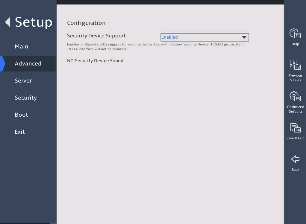
表3-55 Items on the Trusted Computing submenu screen
|
Items |
Description |
Default |
|
Security Device Support |
Select Enabled or Disabled to enable or disable security device support. |
Enabled |
2. TPM security device submenu
图3-77 and 图3-78 show the TPM2.0 submenu screen. The submenu items are described in 表3-56.
图3-77 TPM2.0 submenu screen (1)
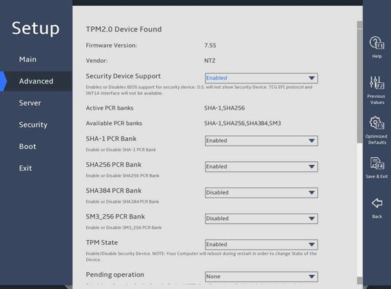
图3-78 TPM2.0 submenu screen (2)
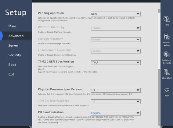
表3-56 Items on TPM2.0 submenu screen
|
Item |
Description |
Default |
|
Firmware Version |
Displays the firmware version. |
N/A |
|
Vendor |
Displays the name of the vendor. |
N/A |
|
Security Device Support |
Select Enabled or Disabled to enable or disable BIOS support for security devices. |
Enabled |
|
Active PCR banks |
Displays the active platform configuration register (PCR) banks. |
N/A |
|
Available PCR Banks |
Displays the available PCR banks. |
N/A |
|
SHA-1 PCR Bank |
Select Enabled or Disabled to enable or disable the SHA-1 PCR bank. |
Enabled |
|
SHA256 PCR Bank |
Select Enabled or Disabled to enable or disable the SHA256 PCR bank. |
Enabled |
|
SHA384 PCR Bank |
Select Enabled or Disabled to enable or disable the SHA384 PCR bank. |
Disabled |
|
SM3_256 PCR Bank |
Select Enabled or Disabled to enable or disable the SM3_256 PCR bank. |
Disabled |
|
TPM State |
Select Enabled or Disabled to enable or disable TPM. |
Enabled |
|
Select the TPM operation to be performed during the next boot process. Options: · None. · TPM Clear—Clears the values of TPM measurements. |
None |
|
|
Platform Hierarchy |
This item is inaccessible. Select Enabled or Disabled to enable or disable platform hierarchy. |
Enabled |
|
Storage Hierarchy |
This item is inaccessible. Select Enabled or Disabled to enable or disable storage hierarchy. |
Enabled |
|
Endorsement Hierarchy |
This item is inaccessible. Select Enabled or Disabled to enable or disable endorsement hierarchy. |
Enabled |
|
TPM 2.0 UEFI Spec Version |
Select the supported Trusted Computing Group (TCG) specification version. Options: · TCG_1_2—Supports Windows 8 and Windows 10. · TCG_2—Supports TCG 2 protocols, TCG 2 event formats, and Windows 10 or higher. |
TCG_2 |
|
Physical Presence Spec Version |
Select the Physical Presence Interface (PPI) specification version to be reported to the OS. Options: · 1.2. · 1.3—Some HCK tests might not support this version. |
1.3 |
|
TPM 2.0 InterfaceType |
Displays the TPM 2.0 interface type. This item is inaccessible. |
N/A |
|
PH Randomization |
Select Enabled or Disabled to enable or disable platform hierarchy randomization. This feature is used only for tests at the development phase. |
Enabled |
3. Trusted Computing submenu (TCM 1.0 module installed)
图3-79 shows a Trusted Computing submenu screen when a TCM 1.0 module is installed. The submenu items are described in 表3-57.
图3-79 Trusted Computing submenu screen (TCM 1.0 module installed)
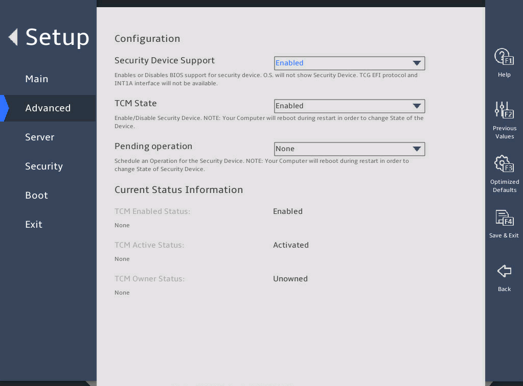
表3-57 Items on the Trusted Computing submenu screen when a TCM 1.0 module is installed
|
Description |
Default |
|
|
Configuration |
||
|
Security Device Support |
Select Enabled or Disabled to enable or disable BIOS support for security devices. |
Enabled |
|
TCM State |
Select Enabled or Disabled to enable or disable TCM. |
Enabled |
|
Pending Operation |
Select the TCM operation to be performed during the next boot process. Options: · None. · TCM Clear—Clears the values of TCM measurements. |
None |
|
Current Status Information |
||
|
TCM Enabled Status |
Displays whether TCM is enabled or disabled. |
N/A |
|
TCM Active Status |
Displays whether TCM is activated or deactivated. |
N/A |
|
TCM Owner Status |
Displays the TCM ownership state. Options are Owned and Unowned. |
N/A |
3.2.4 ACPI Settings submenu
The ACPI Settings submenu contains the ACPI options for you to configure OS-directed configuration and power management of the server as shown in 图3-80. The submenu items are described in 表3-58.
图3-80 ACPI Settings submenu screen
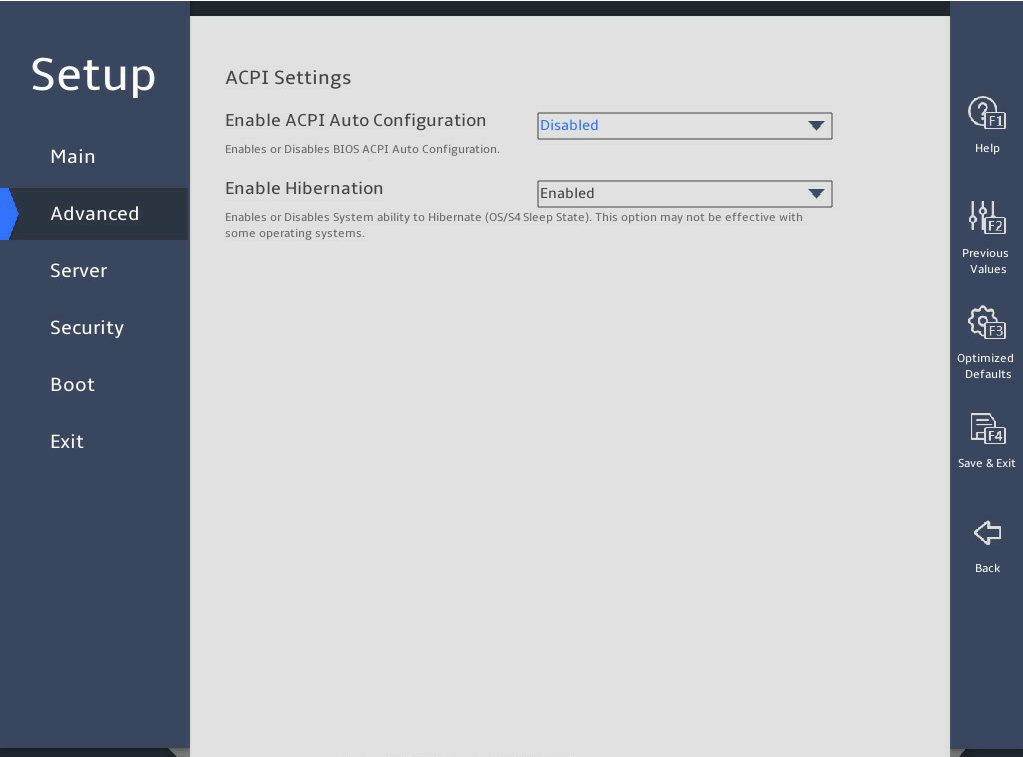
表3-58 Items on the ACPI Settings submenu screen
|
Item |
Description |
Default |
|
Enable ACPI Auto Configuration |
Select Enabled or Disabled to enable or disable ACPI auto configuration. ACPI auto configuration allows the operating system to control and allocate power to the server hardware. |
Disabled |
|
Enable Hibernation |
This item is configurable only when Enable ACPI Auto Configuration is set to Disabled. The configuration does not take effect on some OSs. Select Enabled or Disabled to enable or disable system hibernation. |
Enabled |
3.2.5 Serial Port Console Redirection submenu
图3-81 shows the Serial Port Console Redirection submenu screen, on which you can configure console redirection settings as described in 表3-59.
图3-81 Serial Port Console Redirection submenu screen

表3-59 Items on the Serial Port Console Redirection submenu screen
|
Item |
Description |
Default |
|
COM0 |
||
|
Console Redirection |
Select Enabled or Disabled to enable or disable console redirection on CMO0. If the feature is enabled, the data on a specific physical console or a virtual console will be redirected to the specified system console. |
Enabled |
|
Console Redirection Settings |
This item is available only when Console Redirection is set to Enabled on CMO0. Configure console redirection settings. |
N/A |
|
Legacy Console Redirection |
||
|
Legacy Console Redirection Settings |
Configure console redirection settings. |
N/A |
|
Serial Port for Out-of-Band Management/Windows Emergency Management Services (EMS) |
||
|
Console Redirection EMS |
Select Enabled or Disabled to enable or disable console redirection for Windows emergency management services (EMS). |
Disabled |
|
Console Redirection Settings |
This item is available only when Console Redirection EMS is set to Enabled for Windows EMS. Configure console redirection settings. |
N/A |
2. Console Redirection Settings submenu (COM0)
图3-82 and 图3-83 show a Console Redirection Settings submenu screen for serial port COM0. The submenu items are described in 表3-60.
图3-82 Console Redirection Settings submenu screen (COM0)(1)
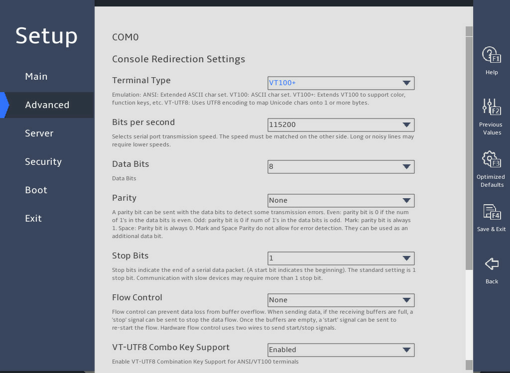
图3-83 Console Redirection Settings submenu screen (COM0)(2)
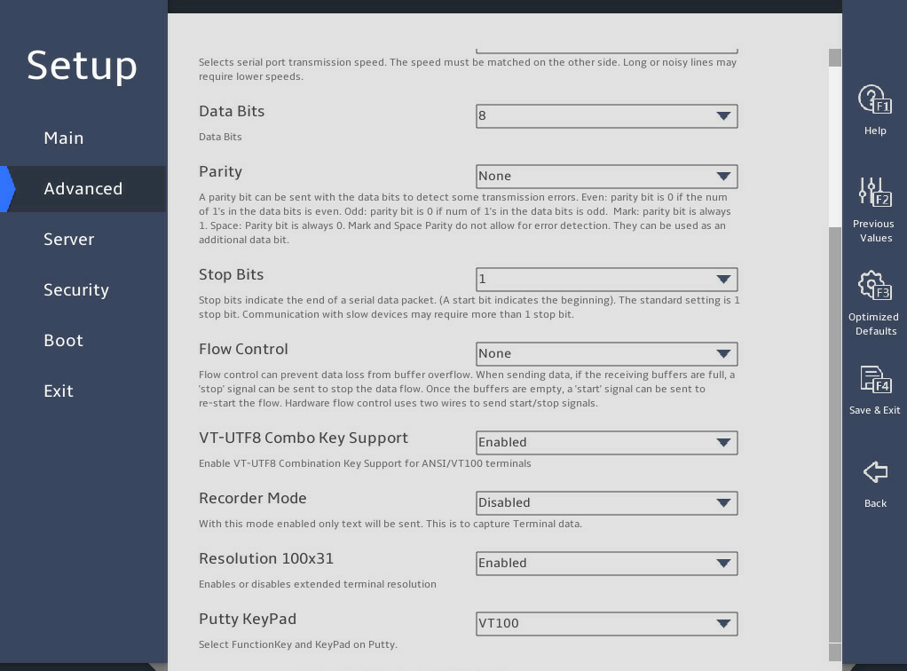
表3-60 Items on the Console Redirection Settings submenu screen (COM0)
|
Item |
Description |
Default |
|
Terminal Type |
Select the type of the terminal used for console redirection. Options: · VT100—Uses a supported VT100 video terminal with the ASCII character set. · VT100+—Uses a supported VT100-plus video terminal and its character set. VT100+ supports colors and function keys. · VT-UTF8—Uses a video terminal with the UTF-8 character set. · ANSI—Uses the ANSI character set, which is an extended ASCII character set. |
VT100+ |
|
Bits Per Second |
Set the baud rate of the serial port in bits per second. Options: · 9600. · 19200. · 38400. · 57600. · 115200. This baud rate setting must match the setting on the remote terminal. As a best practice, set a low speed on a long or noisy serial line. |
115200 |
|
Data Bits |
Set the number of bits used to represent one character of data. Options: · 7. · 8. |
8 |
|
Parity |
Set the parity bit to be sent with the data bits for transmission error detection. Options: · None—Disables the transmission error detection feature. · Even—Sets the parity bit so that the number of ones in the data set is an even number. · Odd—Sets the parity bit so that the number of ones in the data set is an odd number. · Mark—Always sets the parity bit to 1. A parity bit value of 0 indicates that an error has occurred. · Space—Always sets the parity bit to 0. A non-zero parity bit indicates that an error has occurred. |
None |
|
Stop Bits |
Set the number of stop bits used to indicate the end of a serial data packet. Options: · 1. · 2. Two stop bits might be required for communications with a low-speed device. |
1 |
|
Flow Control |
Select a flow control method to prevent data loss from buffer overflow. Options: · None—No flow control is used. · Hardware RTS/CTS—Flow control that uses the ready to send/clear to send (RTS/CTS) signal. When you select this option, make sure it is supported on the serial port. If you enable hardware RTS/CTS on a serial port that does not support hardware flow control (such as a port that uses a USB-to-serial cable), or on a serial port with no cable connected, the following issues might occur: · Failure to load the option ROM of embedded and external PCIe modules. · Screen blackout. · Cursor flickering. |
None |
|
VT-UTF8 Combo Key Support |
Select Enabled or Disabled to enable or disable VT-UTF8 combination key support for ANSI/VT100 terminals. |
Enabled |
|
Recorder Mode |
Select Enabled or Disabled to enable or disable the recorder mode, which is used to capture terminal text data. |
Disabled |
|
Resolution 100×31 |
Select Enabled or Disabled to enable or disable enhanced terminal resolution (100 × 31). |
Enabled |
|
Putty KeyPad |
Select a mode to change the action of the function keys and keypad in PuTTY. Options: · VT100. · LINUX. · XTERMR6. · SCO. · ESCN. · VT400. |
VT100 |
3. Console Redirection Settings (Legacy) submenu
图3-84 shows the Console Redirection Settings submenu screen. The submenu items are described in 表3-61.
图3-84 Console Redirection Settings (Legacy) submenu screen
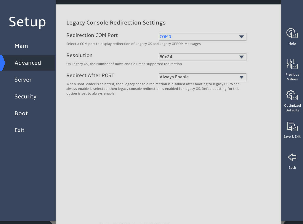
表3-61 Items on the Console Redirection Settings (Legacy) submenu screen
|
Item |
Description |
Default |
|
Redirection COM Port |
Select the CMO port for the OS and Option ROM redirection in Legacy mode. The only option is CMO0. |
N/A |
|
Resolution |
Set the redirection solution. Options: · 80x24. · 80x25. |
80x24 |
|
Redirect After POST |
Select whether to enable or disable redirection after POST. Options: · Always Enable—Always enables redirection after POST. · BootLoader—Disables redirection after the OS is booted in Legacy mode. |
Always Enable |
4. Console Redirection Settings (EMS port) submenu
图3-85 shows a Console Redirection Settings (EMS port) submenu screen. The submenu items are described in 表3-62.
图3-85 Console Redirection Settings (EMS port) submenu screen
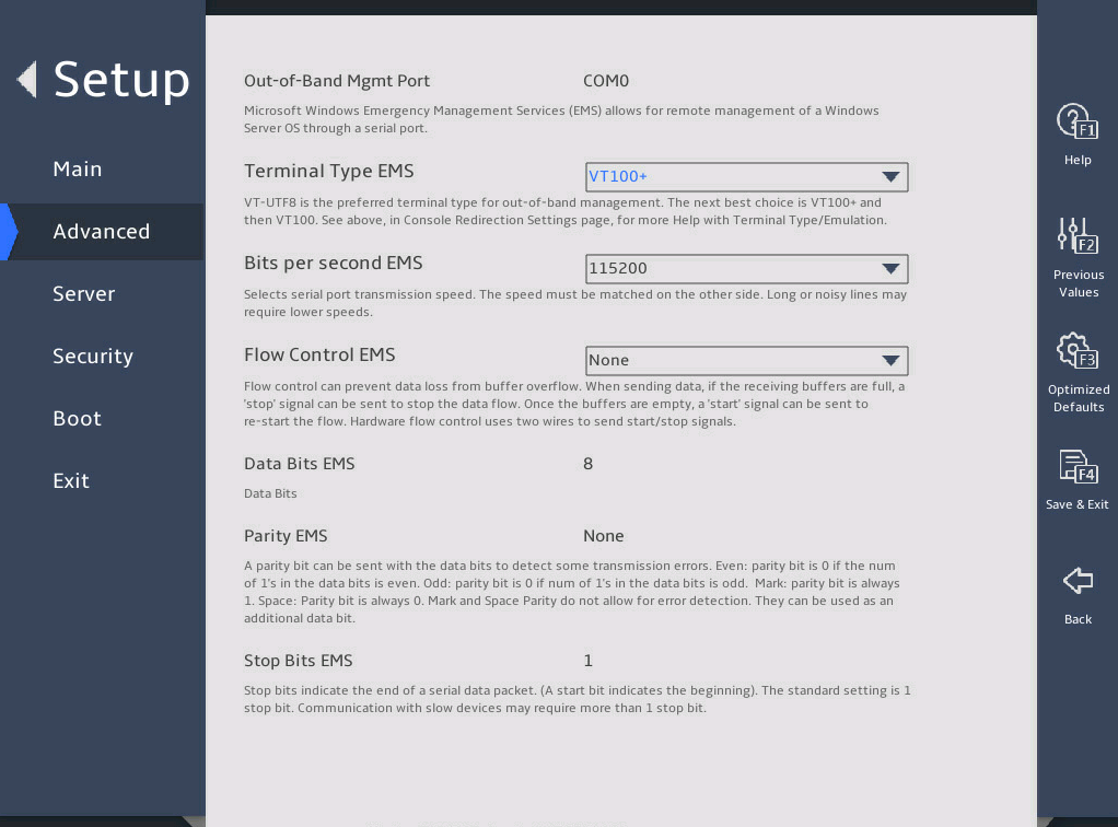
表3-62 Items on the Console Redirection Settings (EMS port) submenu screen
|
Item |
Description |
Default |
|
Out-of-Band Management Port |
Indicate the EMS port. This port allows Microsoft Windows EMS to remotely access the Window OS to collect fault information. |
N/A |
|
Terminal Type EMS |
Select the type of the terminal used for console redirection. Options: · VT100—Uses a supported VT100 video terminal with the ASCII character set. · VT100+—Uses a supported VT100-plus video terminal and its character set. VT100+ supports colors and function keys. · VT-UTF8—Uses a video terminal with the UTF-8 character set. · ANSI—Uses the ANSI character set, which is an extended ASCII character set. |
VT100+ |
|
Bits Per Second EMS |
Set the data transfer rate of the serial port in bits per second. Options: · 9600. · 19200. · 57600. · 115200. This data transfer rate setting must match the setting on the remote terminal. As a best practice, set a low speed on a long or noisy serial line. |
115200 |
|
Flow Control EMS |
Select a flow control method to prevent data loss from buffer overflow. Options: · None—No flow control is used. · Hardware RTS/CTS—Flow control that uses the ready to send/clear to send (RTS/CTS) signal. When you select this option, make sure it is supported on the serial port. · Software Xon/Xoff—Flow control that uses the XON (transmit ON) and XOFF (transmit OFF) control characters. When the data transfer rate exceeds 1200 bits per second, the receiver sends an XOFF to have the sender stop transmission. The sender will resume the transmission only when it receives an XON from the receiver. |
None |
|
Data Bits EMS |
Set the number of bits used to represent one character of data. |
N/A |
|
Parity EMS |
Set the parity bit to be sent with the data bits for transmission error detection. Options: · None—Disables the transmission error detection feature. · Even—Sets the parity bit so that the number of ones in the data set is an even number. · Odd—Sets the parity bit so that the number of ones in the data set is an odd number. · Mark—Always sets the parity bit to 1. A parity bit value of 0 indicates that an error has occurred. · Space—Always sets the parity bit to 0. A non-zero parity bit indicates that an error has occurred. |
None |
|
Stop Bits EMS |
Set the number of stop bits used to indicate the end of a serial data packet. |
N/A |
3.2.6 PCI Subsystem Settings submenu
图3-86 shows the PCI Subsystem Settings submenu screen, on which you can configure PCI subsystem settings as described 表3-63.
图3-86 PCI Subsystem Settings submenu screen
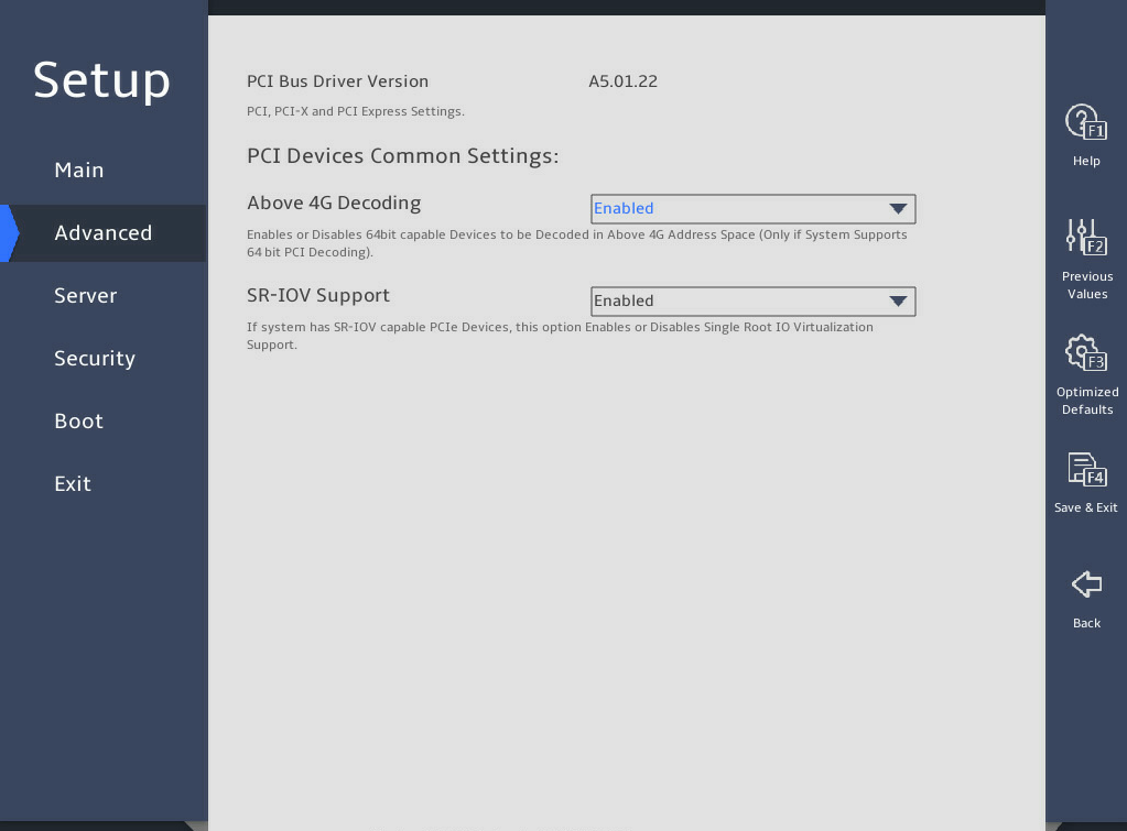
表3-63 Items on the PCI Subsystem Settings submenu screen
|
Item |
Description |
Default |
|
PCI Bus Driver Version |
Displays the PCI bus driver version. |
N/A |
|
PCI Devices Common Settings |
||
|
Above 4G Decoding |
Select Enabled or Disabled to enable or disable decoding of 64-bit PCIe modules in a 4 GB or greater address space. As a best practice, enable this option if the PCIe module has a 4 GB or higher-capacity VRAM. For example, disabling this option can cause an M60 or K80 GPU to get stuck in the EarlyPOST 100% phase, preventing you from accessing the BIOS setup menu or the OS. |
Enabled |
|
SR-IOV Support |
Select Enabled or Disabled to enable or disable support for PCIe single-root I/O virtualization (SR-IOV). SR-IOV virtualizes one physical PCIe module into multiple virtual PCIe modules, each of which can be bound to a virtual machine, thus allowing multiple accesses to the physical PCIe module. With SR-IOV support enabled, the BIOS allocates I/O resources if a PCIe module supports SR-IOV. With SR-IOV support disabled, the OS allocates I/O resources if a PCIe module supports SR-IOV. |
Enabled |
3.2.7 USB Configuration submenu
图3-87 shows the USB Configuration submenu screen, on which you can view connected USB devices and configure USB settings as described in 表3-64.
图3-87 USB Configuration submenu screen
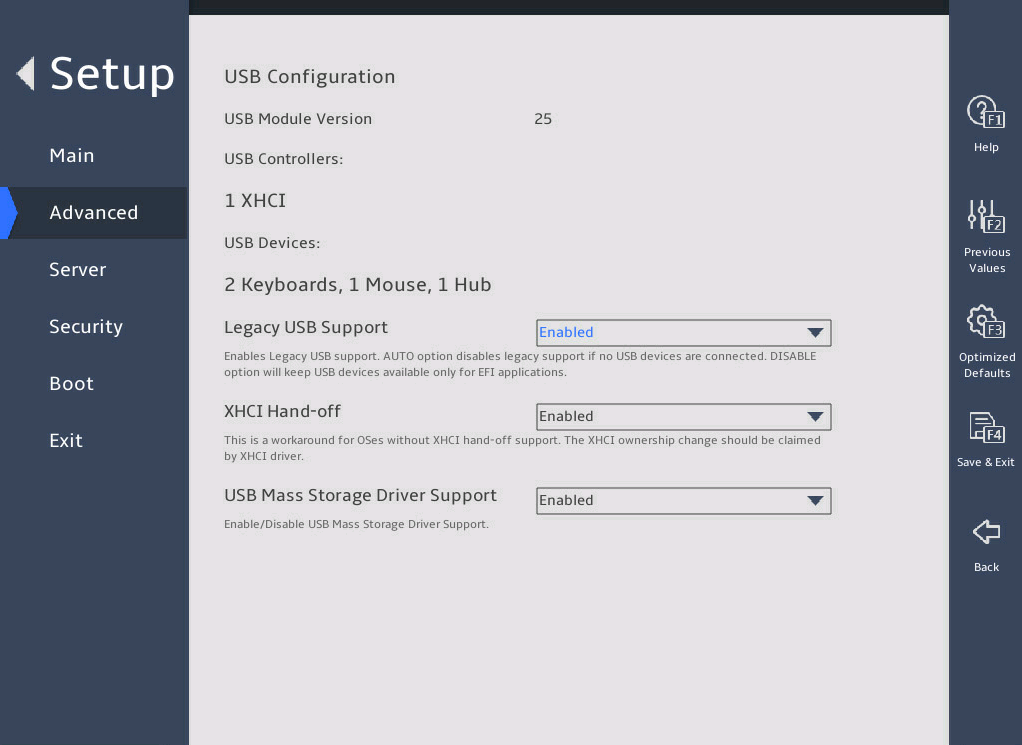
表3-64 Items on the USB Configuration submenu screen
|
Item |
Description |
Default |
|
USB Module Version |
Displays the USB module version. |
N/A |
|
USB Controllers |
Displays the detected USB controllers. The system supports eXtensible Host Controller (XHCI) controllers that support USB 3.0. |
N/A |
|
USB Devices |
Displays the numbers of connected USB devices, including drives, keyboards, mouses, and hubs. The server has one embedded USB hub in addition to the connected USB hubs. |
N/A |
|
Legacy USB Support |
Select whether to enable support for legacy USB devices. Options: · Enabled—Legacy USB support is always enabled. · Disabled—USB devices are available only for UEFI applications. · Auto—The system automatically disables legacy USB support if no USB devices are connected. |
Enabled |
|
XHCI Hand-off |
Select Enabled or Disabled to enable or disable the XHCI hand-off feature. This feature provides a solution for the operating system that does not support XHCI. |
Enabled |
|
USB Mass Storage Driver Support |
Select Enabled or Disabled to enable or disable the support for USB mass storage drivers. NOTE: This field displays USB information depending on USB storage devices installed. |
Enabled |
3.2.8 CSM Configuration submenu
图3-88 shows the CSM Configuration submenu screen, on which you can configure CMS settings as described in 表3-65.
图3-88 CSM Configuration submenu screen
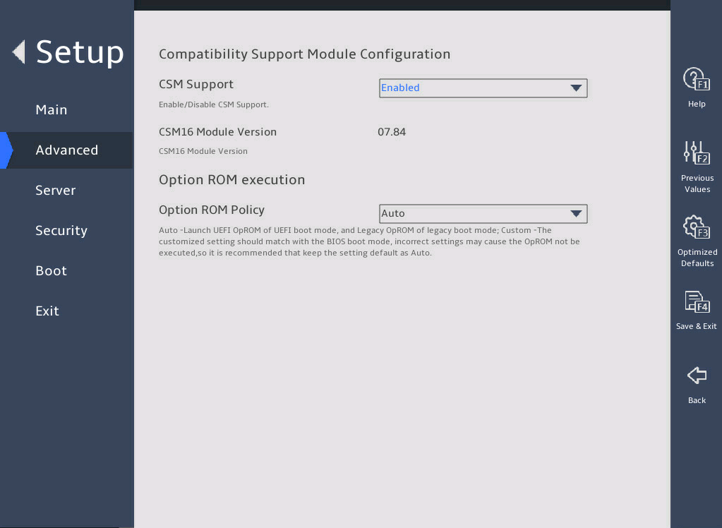
表3-65 Items on the CSM Configuration submenu screen
|
Item |
Description |
Default |
|
CSM Support |
Select Enabled or Disabled to enable or disable support for UEFI-incapable operating systems. You must enable CSM support in legacy boot mode. |
Enabled |
|
CSM16 Module Version |
Displays the version of the CSM 16 module. |
N/A |
|
Option ROM Execution |
Displays ROM execution settings. |
N/A |
|
Option ROM Policy |
Select the option ROM policy. Options: · Auto—Enables the UEFI boot mode for UEFI option ROMs and legacy boot mode for legacy option ROMs. · Custom—Customizes a policy matching with the BIOS boot mode. As a best practice, uses the auto mode to prevent some option ROMs from failing to execute due to incorrect settings. |
Auto |
|
Network |
Select the option ROM load method for network adapters. This option is available when the option ROM policy is in custom mode. Options: · UEFI—Loads the option ROM for network adapters in UEFI boot mode. · Legacy—Loads the option ROM for network adapters in legacy boot mode. |
· In UEFI boot mode: UEFI. · In legacy boot mode: Legacy. |
|
Storage |
Select the option ROM load method for storage devices. This option is available when the option ROM policy is in custom mode. Options: · UEFI—Loads the option ROM for storage devices in UEFI boot mode. · Legacy—Loads the option ROM for storage devices in legacy boot mode. |
· In UEFI boot mode: UEFI. · In legacy boot mode: Legacy. |
|
Video |
Select the option ROM load method for video devices. This option is available when the option ROM policy is in custom mode. Options: · UEFI—Loads the option ROM for video cards in UEFI boot mode. · Legacy—Loads the option ROM for video cards in legacy boot mode. |
· In UEFI boot mode: UEFI. · In legacy boot mode: Legacy. |
|
Other PCI devices |
Select the option ROM load method for other PCI devices such as input devices. This option is available when the option ROM policy is in custom mode. Options: · UEFI—Loads the option ROM for other PCI devices in UEFI boot mode. · Legacy—Loads the option ROM for other PCI devices in legacy boot mode. |
· In UEFI boot mode: UEFI. · In legacy boot mode: Legacy. |
3.2.9 NVMe Configuration submenu
图3-89 shows the NVMe Configuration submenu screen, on which all installed NVMe devices without option ROM are displayed. You can select an NVMe device to view its information as shown in 表3-66.
图3-89 NVMe Configuration submenu screen
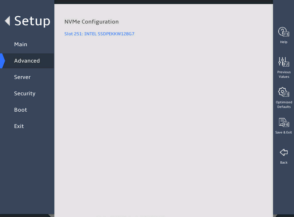
表3-66 Items on the NVMe Configuration submenu screen
|
Item |
Description |
|
Slot 251: INTEL SSDPEKKW128G7 |
Open the submenu for the selected NVMe device. The logical slot number of NVMe devices varies by server model. For more information, see the HDM screen. |
图3-90 shows the NVMe Device Information submenu screen, on which you can view the device settings as described in 表3-67.
图3-90 NVMe Device Information submenu screen
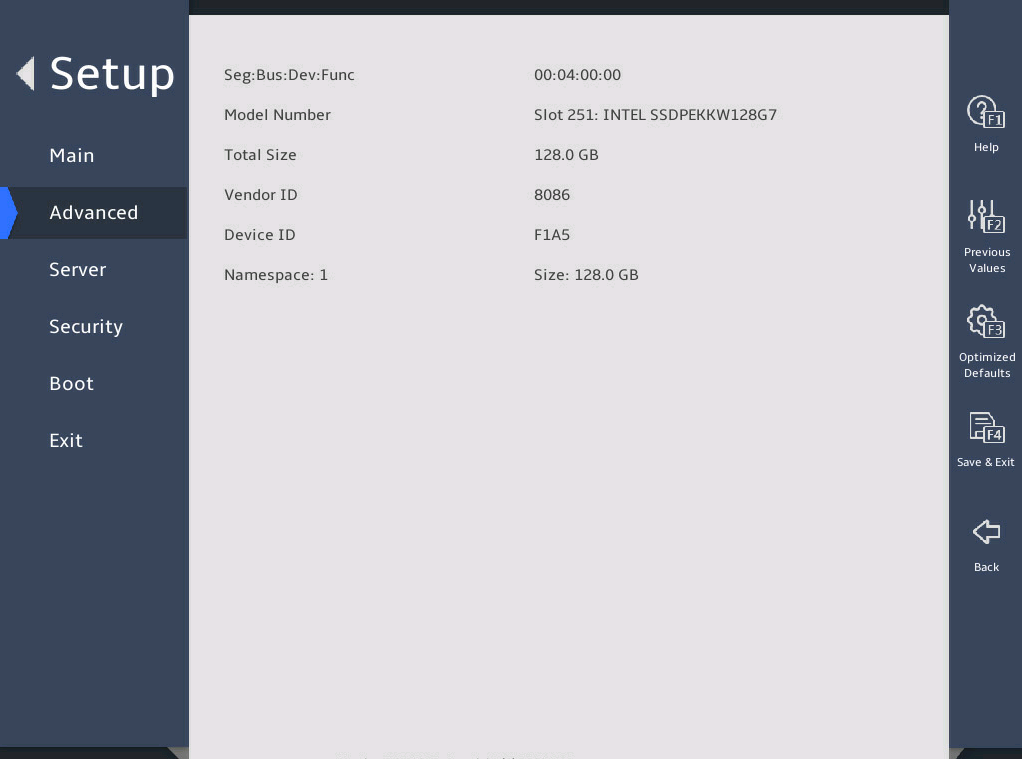
表3-67 Items on the NVMe Device Information submenu screen
|
Item |
Description |
|
Seg:Bus:Dev:Func |
Displays the Seg:Bus:Dev:Func of the NVMe device. |
|
Model Number |
Displays the model number of the NVMe device. |
|
Total Size |
Displays the total size of the NVMe device. |
|
Vendor ID |
Displays the vendor ID of the NVMe device. |
|
Device ID |
Displays the device ID of the NVMe device. |
|
Namespace |
Displays the namespace of the NVMe device. |
3.2.10 Network Configuration submenu
图3-91 shows the Network Configuration submenu screen, on which all Ethernet adapters are displayed. The submenu items are described in 表3-68.
Preboot Execute Environment (PXE) enables a server to load the operating system through the network interface. This feature allows the system to start up independently from local storage devices (such as drives) and locally installed operating systems.
图3-91 Network Configuration submenu screen
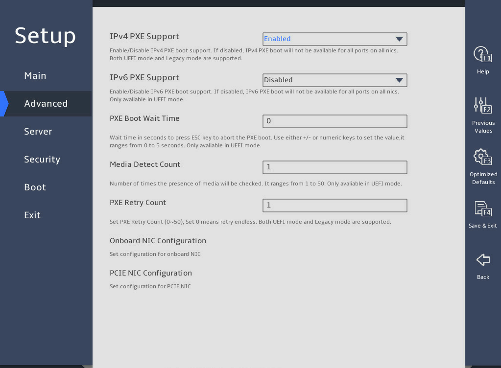
表3-68 Items on the Network Configuration submenu screen
|
Item |
Description |
Default |
|
IPv4 PXE Support |
Select Enabled or Disabled to enable or disable loading the OS over an IPv4 network. If Disabled is selected, the IPv4 PXE boot option will not be created. |
Enabled |
|
IPv6 PXE Support |
This item is not available in Legacy mode. Select Enabled or Disabled to enable or disable loading the OS over an IPv6 network. If Disabled is selected, the IPv6 PXE boot option will not be created. |
Disabled |
|
IPSEC Certificate |
This item is available only for the R6900 G5. Select Enabled or Disabled to enable or disable Internet Key Exchange (IPsec) certificate for Internet Key Exchange (IKE). |
Disabled |
|
PXE Boot Wait Time |
Set the wait time to press ESC key to abort the PXE boot. Value range: 0 to 5, in seconds. |
0 |
|
Media Detect Count |
This item is not available in Legacy mode. Set the maximum number of media presence detections. Value range: 1 to 50. |
1 |
|
PXE Retry Count |
Set the maximum number of PXE retries. Value range: 0 to 50. A value of 0 indicates that the number of PXE retries is not limited. |
1 |
|
Onboard NIC Support |
This item is available only the servers that support onboard NICs. Submenu for configuring onboard NIC ports, as shown in . |
|
|
PCIE NIC Configuration |
Submenu for configuring PCIe NIC port settings, as shown in 图3-93. The submenu items are described in 表3-70. |
N/A |
Onboard NIC Support submenu
图3-92 shows the Onboard NIC Support submenu screen, on which you can configure features described in 表3-69.
图3-92 Onboard NIC Support submenu screen
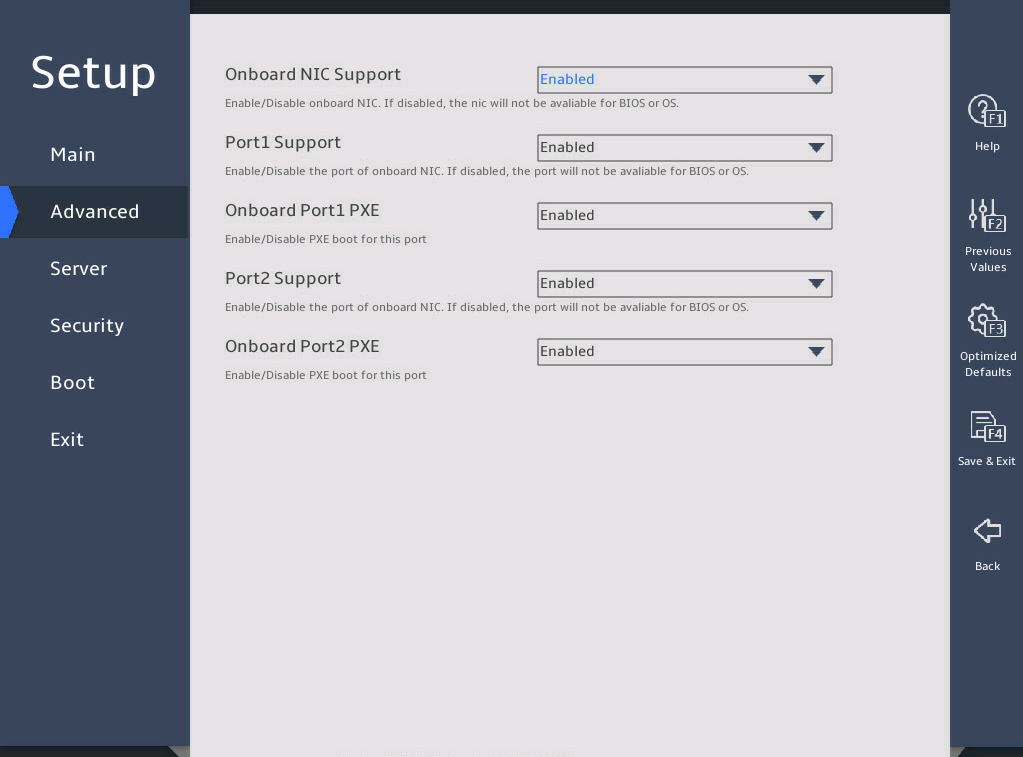
表3-69 Items on the Onboard NIC Support submenu screen
|
Item |
Description |
Default |
|
Onboard NIC Support |
Select Enabled or Disabled to enable or disable the onboard NIC. If you select Disabled, the onboard NIC is not available in the BIOS or OS. |
Enabled |
|
Protx Support |
Select Enabled or Disabled to enable or disable a specific onboard NIC port. |
Enabled |
|
Onboard Portx PXE |
Select Enabled or Disabled to enable or disable PXE on a specific onboard NIC port. |
Enabled |
2. PCIE NIC Configuration submenu
图3-93 shows the PCIE NIC Configuration submenu screen, on which you can configure features described in 表3-70.
图3-93 PCIE NIC Configuration submenu screen
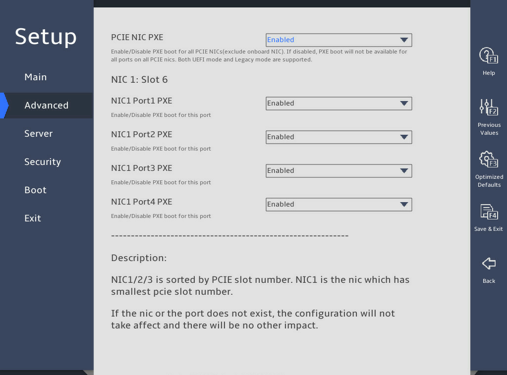
表3-70 Items on the PCIE NIC Configuration submenu screen
|
Item |
Description |
Default |
|
PCIE NIC PXE |
Select Enabled or Disabled to enable or disable PCIe NIC PXE. This feature is supported both in the Legacy mode and the UEFI mode. |
Enabled |
|
NICx: Slot x |
Displays the relations between the NIC ID and the slot ID. The following lists the PXE settings of each port on the NIC. |
N/A |
|
NICm Portn PXE |
Select Enabled or Disabled to enable or disable PXE on a specific NIC port. If this NIC port does not exist, this setting does not take effect. |
Enabled |
3.2.11 Miscellaneous Configuration submenu
图3-94 shows the Miscellaneous Configuration submenu screen, on which you can configure features described in 表3-71.
图3-94 Miscellaneous Configuration submenu screen
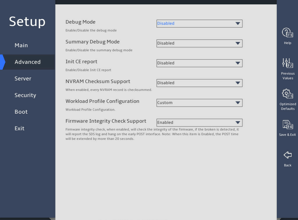
表3-71 Items on the Miscellaneous Configuration submenu screen
|
Item |
Description |
Default |
|
Debug Mode |
Select Enabled or Disabled to enable or disable the server to output BIOS console log messages. |
Disabled |
|
Summary Debug Mode |
Select Enabled or Disabled to enable or disable summary debug mode. |
Disabled |
|
Init CE report |
Select Enabled or Disabled to enable or disable the report of correctable errors at the initialization stage. |
Disabled |
|
NVRAM Checksum Support |
Select Enabled or Disabled to enable or disable NVRAM checksum. If Enabled is selected, each NVRAM data will be checked. |
Disabled |
|
Workload Profile Configuration |
Select the workload profile configuration. For more information, see "Workload profiles (for the R6900 G5 only)." This item does not support out-of-band modification through IPMI or Redfish or in-band modification by using an SCE tool. Options: · Custom. · General Power Efficient Compute. · General Peak Frequency Compute. · Advanced Reliability Mode. · General Throughput Compute. · High Performance Compute (HPC). · Virtualization-Power Efficient. · Virtualization - Performance. · Graphic Processing. · Low Latency. · Transactional Application Processing. This item is only available for the R6900 G5. |
Custom |
|
Firmware Integrity Check Support |
Select Enabled or Disabled to enable or disable firmware integrity check. If Enabled is selected, the server will take 10 more seconds to complete POST. |
Enabled |
3.2.12 Intel(R) VROC SATA/sSATA Controller submenu
The submenus of Intel(R) VROC sSATA controller and Intel(R) VROC SATA controller are available only when the RAID mode is used in the PCH settings.
The submenu screens of Intel(R) VROC sSATA controller and Intel(R) VROC SATA controller are the same. The following uses the submenu screen of Intel(R) VROC SATA controller for example.
图3-95 shows the Intel(R) VROC SATA Controller submenu screen. The submenu items are described in 表3-72.
图3-95 Intel(R) VROC SATA Controller submenu screen
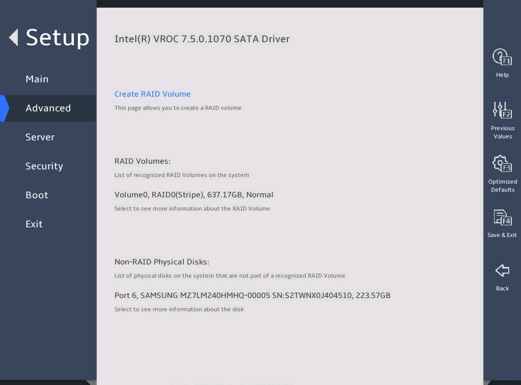
表3-72 Items on the Intel(R) VROC SATA controller submenu screen
|
Item |
Description |
|
Create RAID Volume |
Open the submenu for creating a RAID volume. This option is available only when more than two SATA or sSATA drives are connected to the port managed by the SATA or sSATA controller. |
|
RAID Volumes |
Displays the list of the created RAID volumes. |
|
Volume0,RAID0(Stripe),424.77GB,Normal |
Displays summary information about managed RAID volumes, including their volume name, RAID level, capacity, and state, for example, Volume0, RAID0 (Stripe), 424.77GB, Normal. |
|
Non-RAID Physical Disks |
Displays the list of the physical drives that have not been used to build RAID volumes. |
|
Port 0,INTEL SSDSC2BB480G7 SN:PHDV702001YJ480BGN,447.14GB |
Displays the information about non-RAID physical drives, including port number, physical drive name, serial number, and size. |
2. Create RAID Volume submenu
图3-96 and 图3-97 show the Create RAID Volume submenu screen. The submenu items are described in 表3-73.
图3-96 Create RAID Volume submenu screen (1)
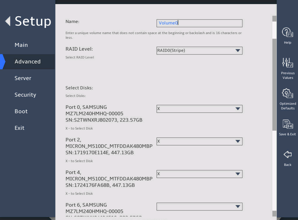
图3-97 Create RAID Volume submenu screen (2)
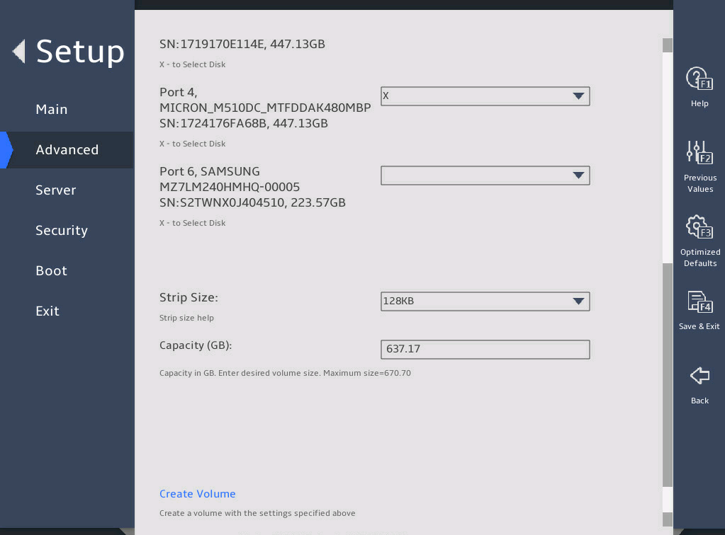
表3-73 Items on the Create RAID Volume submenu screen
|
Item |
Description |
Default |
|
|
Create RAID volume |
|||
|
Name |
Enter the name of the RAID volume. Make sure the name does not contain backslashes (\) or spaces. To avoid operation errors, make sure the name does not contain tildes (~), exclamation points (!), at signs (@), pound signs (#), forward slashes (/), or parentheses (()) as a best practice. |
N/A |
|
|
RAID Level |
Select a RAID level. Options: · RAID0(Stripe). · RAID1(Mirror). · RAID5(Parity)—This option is available only when a minimum of three drives are present. · RAID10(RAID0+1)—This option is available only when a minimum of four drives are present. |
RAID0(Stripe) |
|
|
Select Disks |
|||
|
All available drives, for example: Port 0,INTEL SSDSC2BB480G7 SN:PHDV702001YJ480BGN,447.14GB |
Select drives over which you want to create the RAID volume. The selected drive is represented by the symbol X. |
No drives are selected. |
|
|
Stripe Size |
Set the stripe size of the RAID volume. |
N/A |
|
|
Capacity(GB) |
Displays the total capacity of the RAID volume, in GB. |
N/A |
|
|
Create Volume |
Create a RAID volume. To view information about the configured RAID volumes, select All Intel VMD Controllers. |
N/A |
|
图3-98 Create Volume confirmation submenu screen
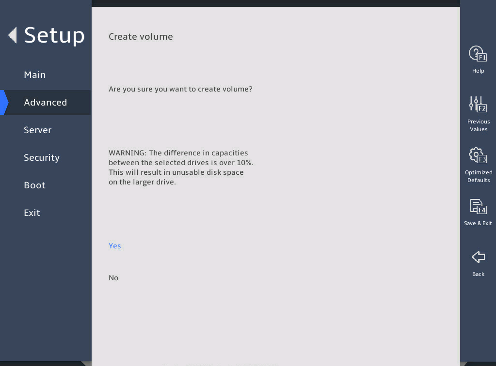
3. RAID VOLUME INFO submenu
图3-99 and 图3-100 show the RAID VOLUME INFO submenu screen. The submenu items are described in 表3-74.
图3-99 RAID VOLUME INFO submenu screen (1)
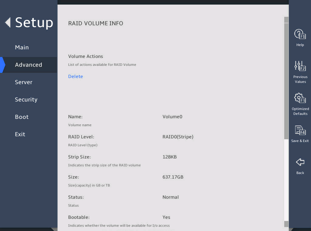
图3-100 RAID VOLUME INFO submenu screen (2)
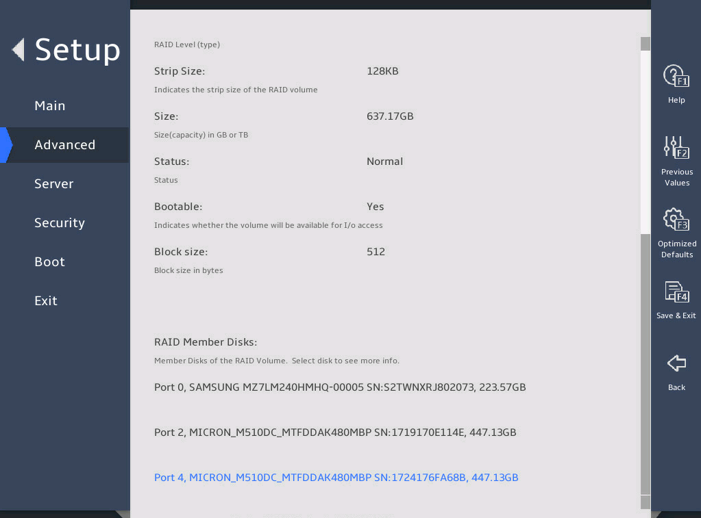
表3-74 Items on the RAID VOLUME INFO submenu screen
|
Item |
Description |
|
Volume Actions |
|
|
Delete |
All data in the member drives of the volume are permanently deleted when the volume is deleted. As a best practice to avoid data loss, back up the data before you delete a volume. To delete the RAID volume, select this item, and then select Yes to confirm the deletion, as shown in 图3-101. |
|
Name |
Displays the name of the RAID volume. |
|
RAID Level |
Displays the RAID level. |
|
Strip Size |
Displays the stripe size of the RAID volume. |
|
Size |
Displays the capacity of the RAID volume. |
|
Status |
Displays the state of the RAID volume. |
|
Bootable |
Displays whether the RAID volume is bootable. |
|
Block Size |
Displays the block size of the RAID volume, in bytes. |
|
RAID Member Disks |
|
|
Member drives of the RAID, for example, Port 0, SAMSUNG MZ7LM240HMHQ-00005 SN:S2WNXR_J802073,223.57GB |
To manage a member drive or view its detailed information, select that drive and the RAID member drive management submenu opens. |
4. Delete Confirm submenu
图3-101 shows the Delete Confirm submenu screen. The submenu items are described in 表3-75.
图3-101 Delete Confirm submenu screen
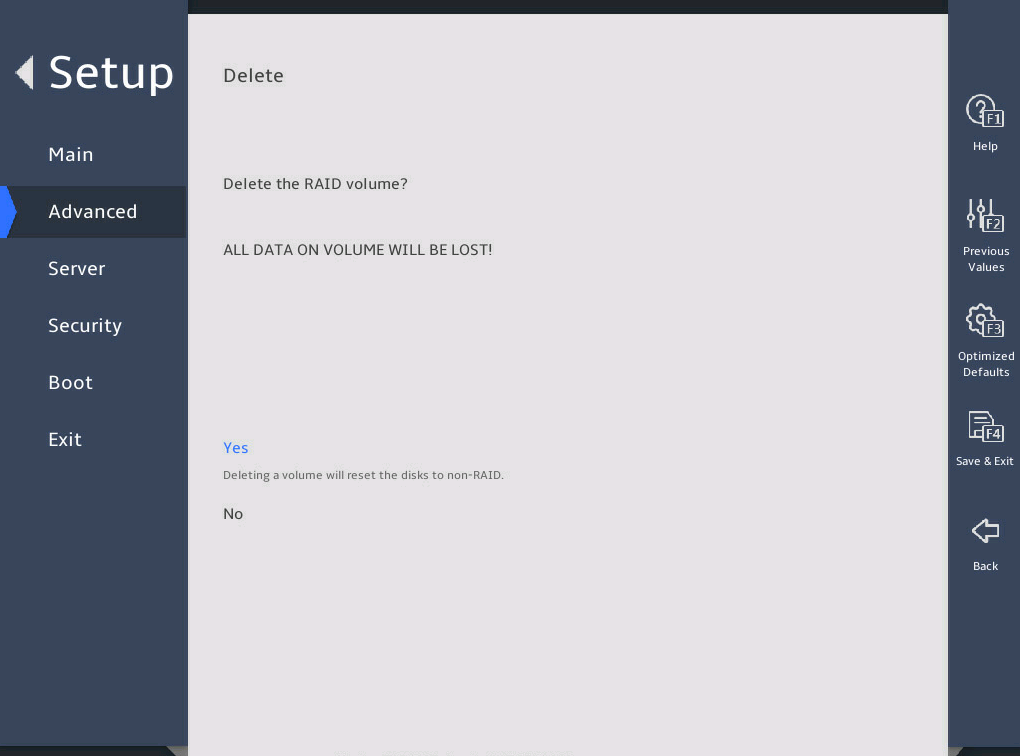
表3-75 Items on the Delete Confirm submenu screen
|
Item |
Description |
|
Delete the RAID volume. After deletion, all data on this volume will be lost. |
|
|
Yes |
Select Yes and press Enter to delete this volume. |
|
No |
Select No and press Enter to cancel the deletion of this volume. |
5. PHYSICAL DISK INFO submenu
图3-102 and 图3-103 show the PHYSICAL DISK INFO submenu screen. The submenu items are described in 表3-76.
图3-102 PHYSICAL DISK INFO submenu screen (1)
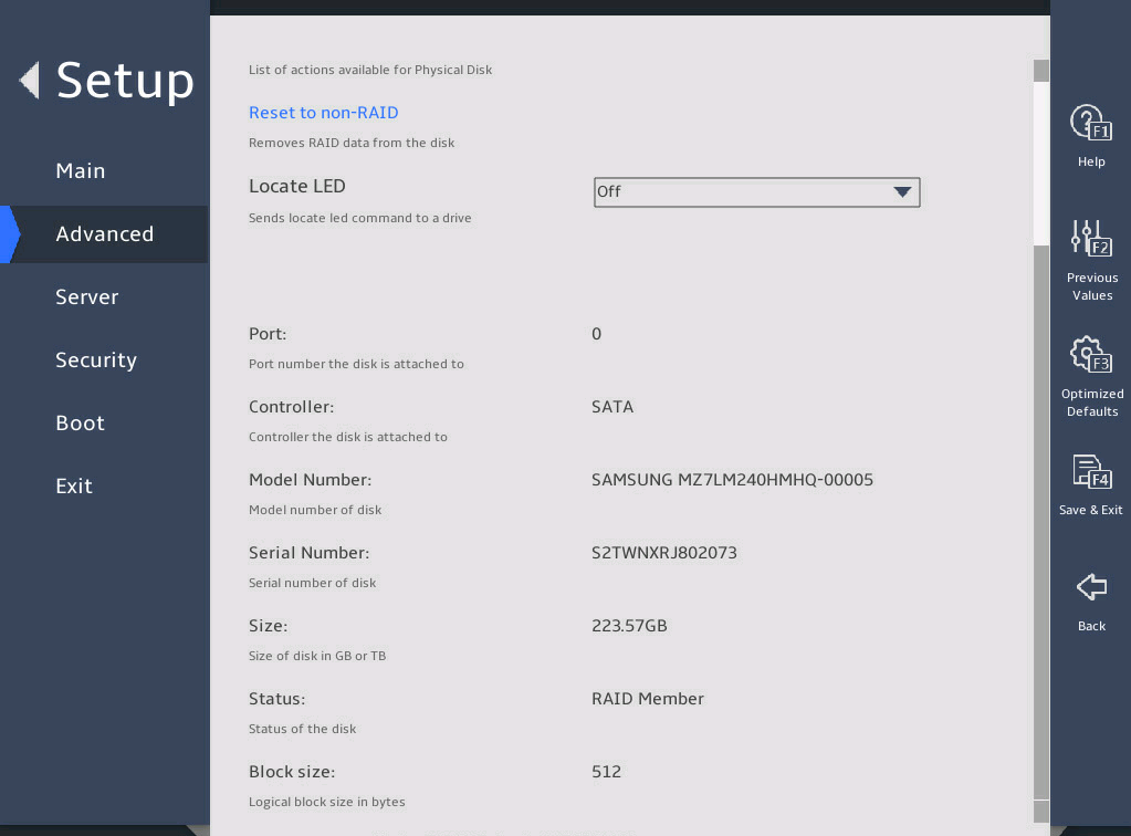
图3-103 PHYSICAL DISK INFO submenu screen (2)
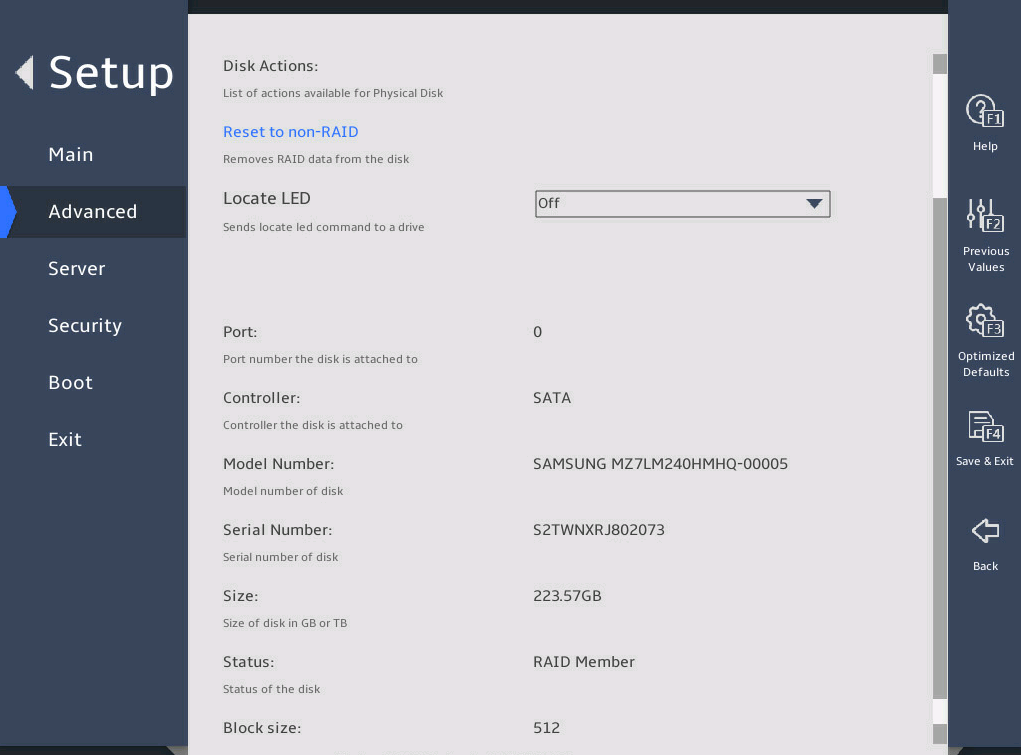
表3-76 Items on the PHYSICAL DISK INFO submenu screen
|
Item |
Description |
|
Disk Actions |
|
|
Reset to non-RAID |
This action deletes all data on the drive. As a best practice to avoid data loss, back up the data before you perform this action. To remove the drive from the RAID array, select this item, and then select Yes to confirm the deletion, as shown in 图3-104. |
|
Locate LED |
Turn on or turn off the locate LED. |
|
Port |
Displays the port number of the drive. |
|
Controller |
Displays the drive controller information, which is SATA in this example. |
|
Model Number |
Displays the model number of the drive. |
|
Serial Number |
Displays the serial number of the drive. |
|
Size |
Displays the capacity of the drive. |
|
Status |
Displays whether the drive is a RAID member. |
|
Block Size |
Displays the block size of the drive, in bytes. |
6. Reset to non-RAID submenu
图3-104 shows the Reset to non-RAID submenu screen. The submenu items are described in 表3-77.
图3-104 Reset to non-RAID submenu screen
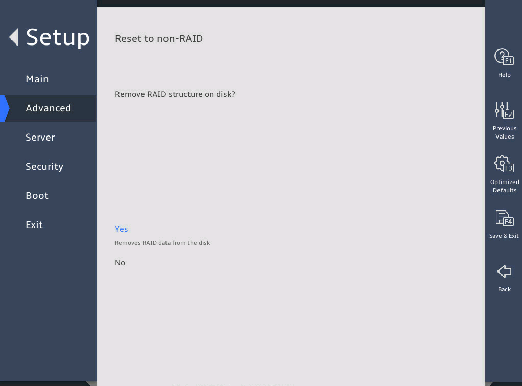
表3-77 Items on the Reset to non-RAID submenu screen
|
Item |
Description |
|
Reset the RAID volume. After resetting, all data on this volume will be deleted. |
|
|
Yes |
Select Yes and press Enter to reset this volume. |
|
No |
Select No and press Enter to cancel the deletion of this volume. |
7. Non-RAID Physical Disk submenu
图3-105 and 图3-106 show the Non-RAID Physical Disk submenu screen for a non-RAID physical drive. On the screen, you can view information about the drive and set the drive as a spare or journaling drive, as described in 表3-78.
图3-105 Non-RAID Physical Disk submenu screen (1)
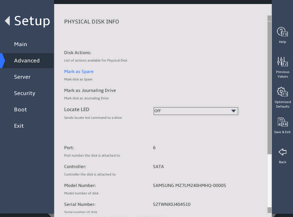
图3-106 Non-RAID Physical Disk submenu screen (2)
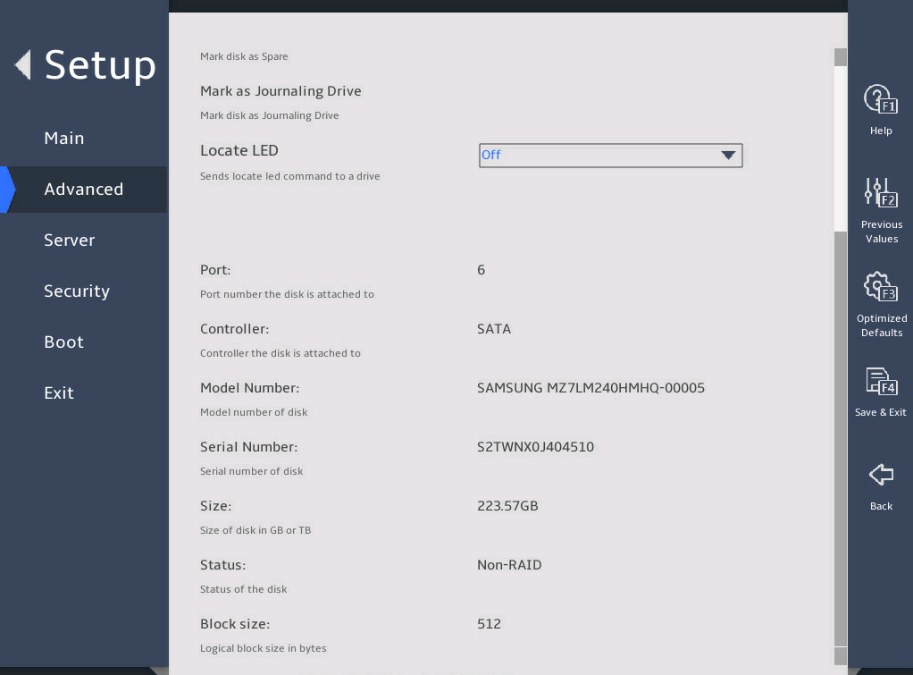
表3-78 Items on the Non-RAID Physical Disk submenu screen
|
Item |
Description |
|
Disk Actions |
|
|
Mark as Spare |
Setting a drive as a spare drive deletes all data on that drive. As a best practice to avoid data loss, back up the data before you perform this action. To specify the drive as a spare drive, select this item, and then select Yes to confirm the action, as shown in 图3-107 A spare drive cannot be used to build a RAID volume. |
|
Mark as Journaling Drive |
Setting a drive as a journaling drive deletes all data on that drive. As a best practice to avoid data loss, back up the data before you perform this action. To specify the drive as a journaling drive, select this item, and then select Yes to confirm the action, as shown in 图3-108. A journaling drive cannot be used to build a RAID volume. |
|
Locate LED |
Turn on or turn off the locate LED. |
|
Port |
Displays the port number of the drive. |
|
Controller |
Displays drive controller information, which is SATA in this example. |
|
Model Number |
Displays the model number of the drive. |
|
Serial Number |
Displays the serial number of the drive. |
|
Size |
Displays the capacity of the drive. |
|
Status |
Displays whether the drive is a RAID member. |
|
Block Size |
Displays the block size of the drive, in bytes. |
8. Mark as Spare submenu
图3-107 shows the Mark as Spare submenu screen. The submenu items are described in 表3-79.
图3-107 Mark as Spare submenu screen
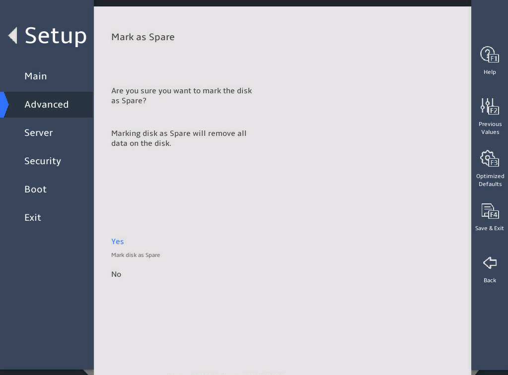
表3-79 Items on the Mark as Spare submenu screen
|
Item |
Description |
|
Yes |
Setting a drive as a spare drive deletes all data on that drive. As a best practice to avoid data loss, back up the data before you perform this action. To specify the drive as a spare drive, select this item, and then select Yes to confirm the action. |
|
No |
Select No and press Enter to cancel the marking of a disk as a spare drive. |
9. Mark as Journaling Drive submenu
图3-108 shows the Mark as Journaling Drive submenu screen. The submenu items are described in 表3-80.
图3-108 Mark as Journaling Drive submenu screen
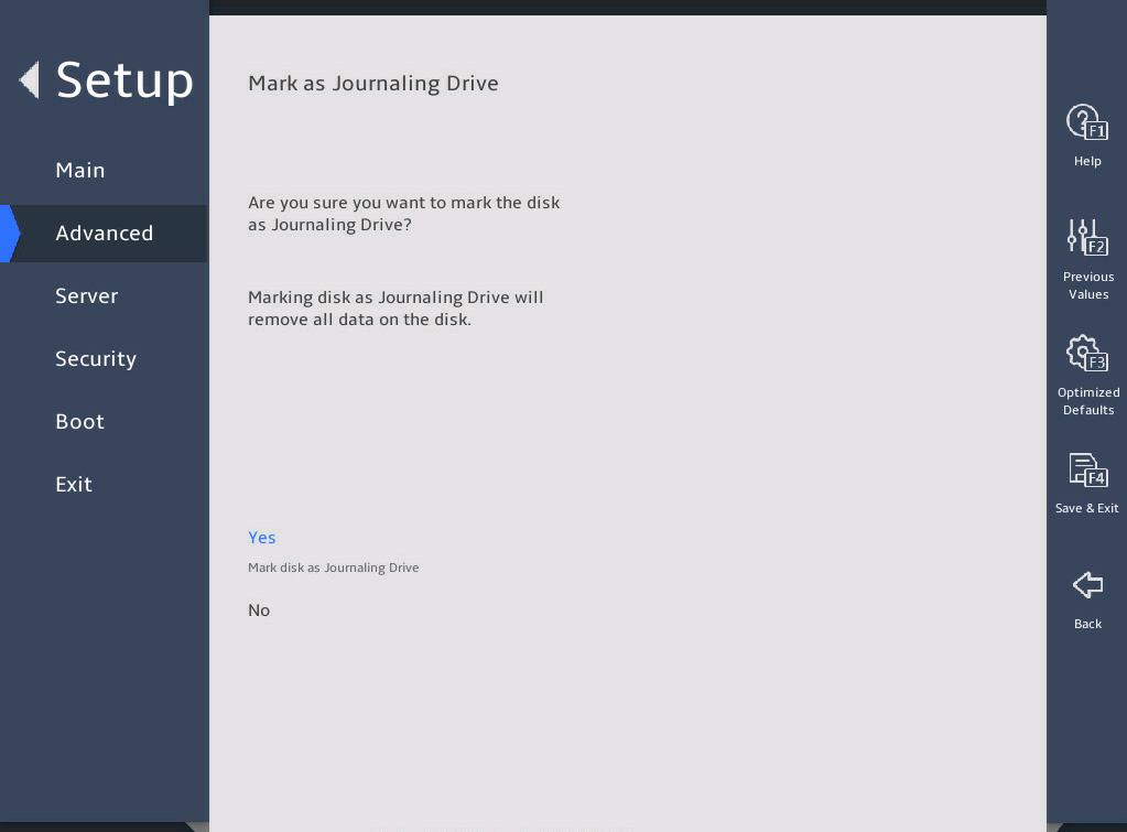
表3-80 Items on the Mark as Journaling Drive submenu screen
|
Item |
Description |
|
Yes |
Setting a drive as a journaling drive deletes all data on that drive. As a best practice to avoid data loss, back up the data before you perform this action. To specify the drive as a journaling drive, select this item, and then select Yes to confirm the action. |
|
No |
Select No and press Enter to cancel the marking of a disk as a journaling drive. |
3.2.13 Intel(R) Virtual RAID on CPU submenu
Intel® Virtual RAID on CPU (Intel VROC) is a RAID solution specifically designed for NVMe-based SSDs. 图3-109 displays the Intel(R) Virtual RAID on CPU submenu. The menu items are described in 表3-81.
The Intel® Virtual RAID on CPU submenu screen displays NVMe drive information only when VMD is enabled. If the VMD is disabled, NVMe drive information is displayed on the Advanced or NVMe Configuration screen, depending on whether NVMe drives contain OptionRom. For more information, see "Advanced menu" or "NVMe Configuration submenu."
图3-109 Intel(R) virtual RAID on CPU submenu screen

表3-81 Items on the Intel(R) Virtual RAID on CPU submenu screen
|
Item |
Description |
|
RAID Volumes |
Displays all the created RAID volumes. |
|
Volume0, RAID0(Stripe),796.44GB,Normal |
Displays information about the created RAID volumes. Volume0: RAID name. RAID0: RAID level. 796.44GB(Size): This size of the RAID. Normal: The status of the RAID. |
|
Non-RAID Physical Disks |
Displays physical drives that have not been used to create RAID volumes. |
2. Create RAID Volume submenu
图3-110 and 图3-111 show the Create RAID Volume submenu screen.
The menu items are described in 表3-82.
图3-110 Create RAID Volume submenu screen (1)

图3-111 Create RAID Volume submenu screen (2)

表3-82 Items on the Create RAID Volume submenu screen
|
Item |
Description |
Default |
|
|
Create RAID Volume |
|||
|
Name |
Specify the name of the RAID. Volume0: The name of the RAID to be created. To avoid operation errors, make sure the name does not contain tildes (~), exclamation points (!), at signs (@), pound signs (#), forward slashes (/), or parentheses (()) as a best practice. |
N/A |
|
|
RAID Level |
Specify the RAID level. Options: · RAID0(Stripe). · RAID1(Mirror). · RAID5(Parity). · RAID10(RAID0+1). |
RAID0 |
|
|
Enable RAID spanned over VMD Controllers |
Enable RAID spanned over VMD controllers. When this item is selected, you can choose the drives controlled by VMD0 and VMD1 controllers to create a RAID. |
N/A |
|
|
Select Disks |
Select drives over which you want to create the RAID volume. |
N/A |
|
|
INTEL SSDPE7KX020T7 SN:PHLF7330003S2P0LGN 1863.02GB Port 1:0,Slot 105,CPU0,VMD0,BDF 08:00.0 |
The selected drive is represented by the symbol X. |
No drives are selected. |
|
|
Strip Size |
Set the stripe size of the RAID volume. |
N/A |
|
|
Capacity(GB) |
Specify the capacity of the RAID volume, in GB. |
N/A |
|
|
Create Volume |
Select to create a RAID volume. Then, the confirm submenu screen opens as shown in 图3-112. |
N/A |
|
图3-112 Create Volume Confirm submenu screen
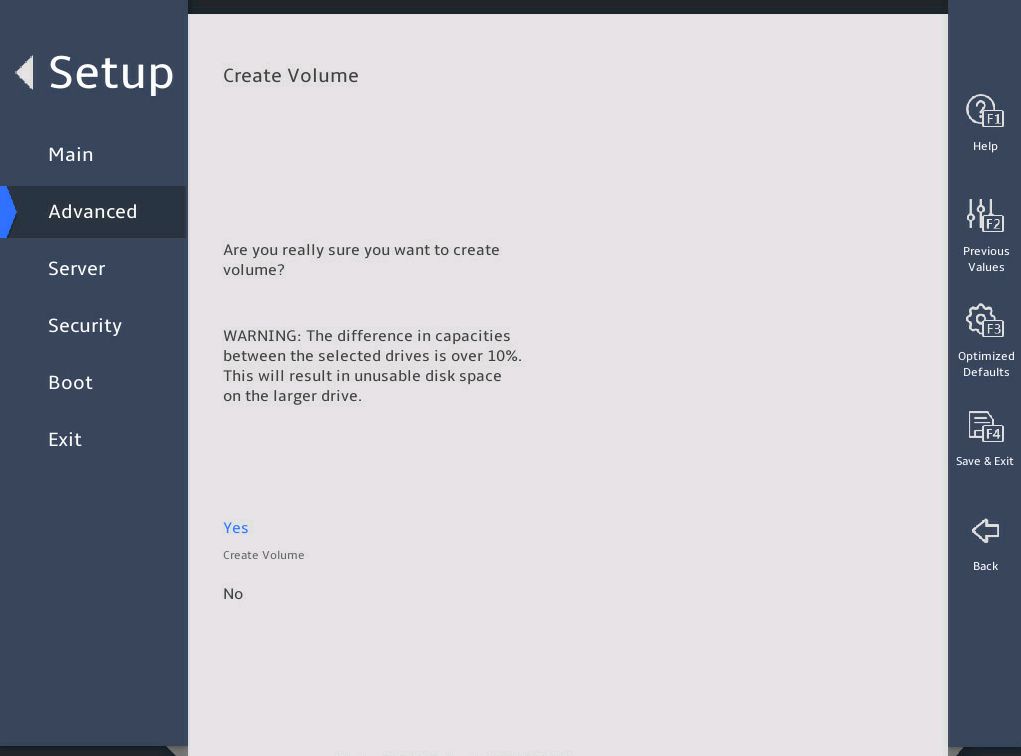
3. Created RAID volume information submenu
图3-113 and 图3-114 show the Created RAID Volume information submenu screen.
The menu items are described in 表3-83.
图3-113 Created RAID volume information submenu screen (1)
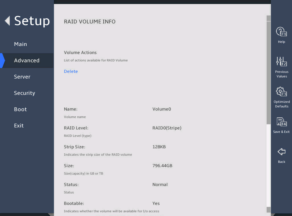
图3-114 Created RAID volume information submenu screen (2)
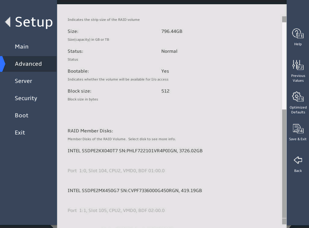
表3-83 Items on the Created RAID Volume submenu screen
|
Item |
Description |
|
Delete |
Select Delete and press Enter to delete a created RAID volume. |
|
Name |
Displays the name of the RAID volume. |
|
RAID Level |
Displays the level of the RAID. |
|
Strip Size |
Displays the size of the RAID strip. |
|
Size |
Displays the size of the RAID, in GB or TB. |
|
Status |
Displays the status of the RAID. |
|
Bootable |
Indicates whether the volume can be used for system boot. |
|
Block Size |
Displays the size of a block, in bytes. |
|
RAID Member Disks |
Displays the member disks of the RAID volume. |
4. Delete submenu
图3-115 shows the Delete submenu screen.
The menu items are described in 表3-84.
图3-115 Delete submenu screen

表3-84 Items on the Delete submenu screen
|
Item |
Description |
|
Delete the RAID volume. After deletion, all data on this volume will be lost. |
|
|
Yes |
Select Yes and press Enter to delete this volume. |
|
No |
Select No and press Enter to cancel the deletion of this volume. |
5. RAID Member Disks submenu
图3-116 and 图3-117 show the RAID Member Disks submenu screen. The screen is similar for all RAID member disks.
The menu items are described in 表3-85.
图3-116 RAID Member Disks submenu screen (1)
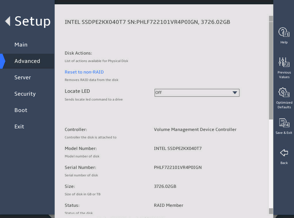
图3-117 RAID Member Disks submenu screen (2)
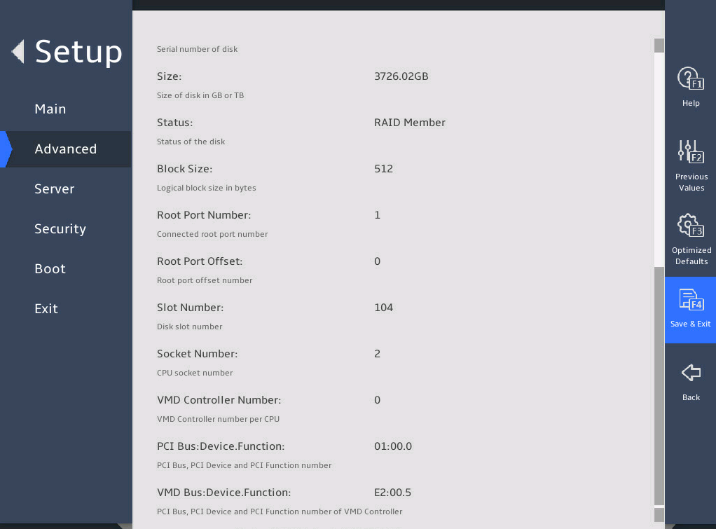
表3-85 Items on the RAID Member Disks submenu screen
|
Item |
Description |
|
Disk Actions |
|
|
Reset to non-RAID |
This action deletes all data on the drive. As a best practice to avoid data loss, back up the data before you perform this action. To remove the drive from the RAID array, select this item, and then select Yes to confirm the deletion, as shown in 图3-118. |
|
Locate LED |
Turn on or turn off the locate LED. |
|
Controller |
Displays controller information, which is Volume Management Device Controller in this example. |
|
Model Number |
Displays the model number of the drive. |
|
Serial Number |
Displays the serial number of the drive. |
|
Size |
Displays the capacity of the drive. |
|
Status |
Displays whether the drive is a RAID member. |
|
Block Size |
Displays the block size of the drive, in bytes. |
|
Root Port Number |
Displays the root port number of the drive. |
|
Root Port Offset |
Displays the root port offset of the drive. |
|
Slot Number |
Displays the slot number of the drive. |
|
Socket Number |
Displays the slot number of the processor for the drive. |
|
VMD Controller Number |
Displays controller information. |
|
PCI Bus:Device.Function |
Displays the Bus:Dev.Func of the drive. |
|
VMD Bus:Device.Function |
Displays the Bus:Dev.Func of VMD controller of the drive. |
6. Reset to non-RAID submenu
图3-118 shows the Reset to non-RAID screen. The submenu items are described in 表3-86.
图3-118 Reset to non-RAID submenu screen
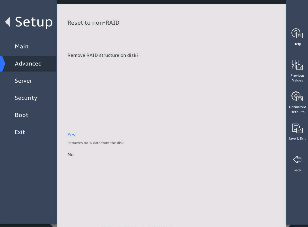
表3-86 Items on the Reset to non-RAID submenu screen
|
Item |
Description |
|
Reset the RAID volume. After resetting, all data on this volume will be deleted. |
|
|
Yes |
Select Yes and press Enter to reset this volume. |
|
No |
Select No and press Enter to cancel the deletion of this volume. |
7. Non-RAID Physical Disk submenu
图3-119 and 图3-120 shows the Non-RAID Physical Disk submenu screen for a non-RAID physical drive. The submenu items are described in 表3-87.
图3-119 Non-RAID Physical Disk submenu screen (1)
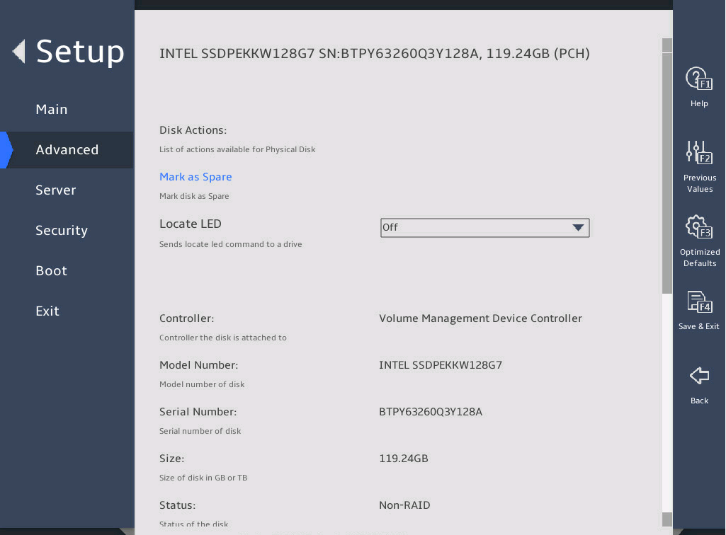
图3-120 Non-RAID Physical Disk submenu screen (2)
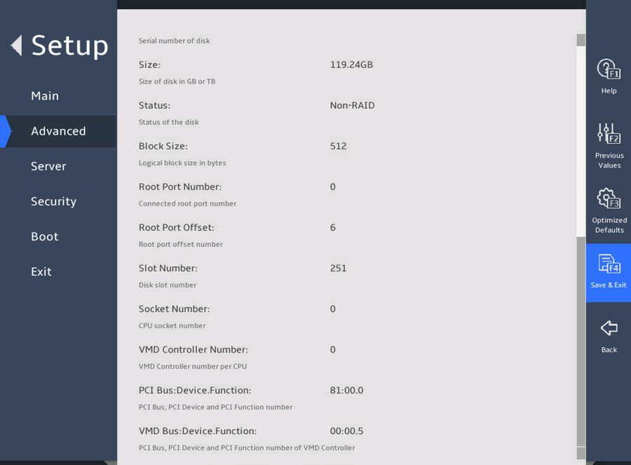
表3-87 Items on the Non-RAID Physical Disk submenu screen
|
Item |
Description |
|
Disk Actions |
|
|
Mark as Spare |
Setting a drive as a spare drive deletes all data on that drive. As a best practice to avoid data loss, back up the data before you perform this action. To specify the drive as a spare drive, select this item, and then select Yes to confirm the action, as shown in 图3-121. A spare drive cannot be used to build a RAID volume. |
|
Locate LED |
Turn on or turn off the locate LED. |
|
Controller |
Displays controller information, which is Volume Management Device Controller in this example. |
|
Model Number |
Displays the model number of the drive. |
|
Serial Number |
Displays the serial number of the drive. |
|
Size |
Displays the capacity of the drive. |
|
Status |
Displays whether the drive is a RAID member. |
|
Block Size |
Displays the block size of the drive. |
|
Root Port Number |
Displays the root port number of the drive. |
|
Root Port Offset |
Displays the root port offset of the drive. |
|
Slot Number |
Displays the slot number of the drive. |
|
Socket Number |
Displays the slot number of the processor for the drive. |
|
VMD Controller Number |
Displays controller information. |
|
PCI Bus:Device.Function |
Displays the Bus:Dev.Func of the drive. |
|
VMD Bus:Device.Function |
Displays the Bus:Dev.Func of the VMD controller of the drive. |
8. Mark as Spare submenu
图3-121 shows the Mark as Spare submenu screen. The submenu items are described in 表3-88.
图3-121 Mark as Spare submenu screen

表3-88 Items on the Mark as Spare submenu screen
|
Item |
Description |
|
Disk Actions |
|
|
Yes |
Setting a drive as a spare drive deletes all data on that drive. As a best practice to avoid data loss, back up the data before you perform this action. To specify the drive as a spare drive, select Yes to confirm the action, as shown in 图3-121. |
|
No |
Select No and press Enter to cancel this action. |
3.2.14 Driver Health submenu
图3-122 shows the Driver Health submenu screen, on which you can view the health state of a driver or controller. The submenu items are described in 表3-89.
图3-122 Driver Health submenu screen
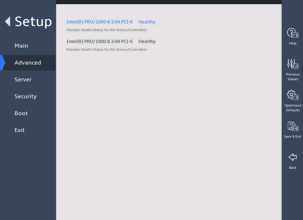
表3-89 Items on the Driver Health submenu screen
|
Item |
Description |
|
Intel® PRO/1000 8.3.04 PCI-E |
Displays the health state of a driver or a controller. Options: · Healthy—Normal. · Failed—Abnormal. If the state is Failed, press Enter and follow the instructions to repair the driver or controller. The repair method varies by driver or controller. |
3.2.15 iSCSI Configuration submenu (for the B5700, R5300, and R5500 servers)
图3-123 shows the iSCSI Configuration submenu screen, on which you can configure iSCSI settings as described in 3.2.15 (2).
图3-123 iSCSI Configuration submenu screen
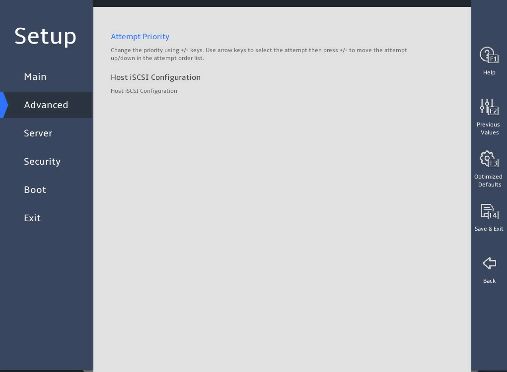
(2) Items on the iSCSI Configuration submenu screen
|
Item |
Description |
Default |
|
Attempt Priority |
Set the attempt priority. Options: · Host Attempt—Set the host with the highest priority. · Redfish Attempt—Set Redfish with the highest priority. |
Host Attempt |
|
Host iSCSI Configuration |
Submenu for configuring host iSCSI settings. |
N/A |
图3-124 shows the Host iSCSI Configuration submenu screen. The submenu items are described in 表3-90.
图3-124 Host iSCSI Configuration
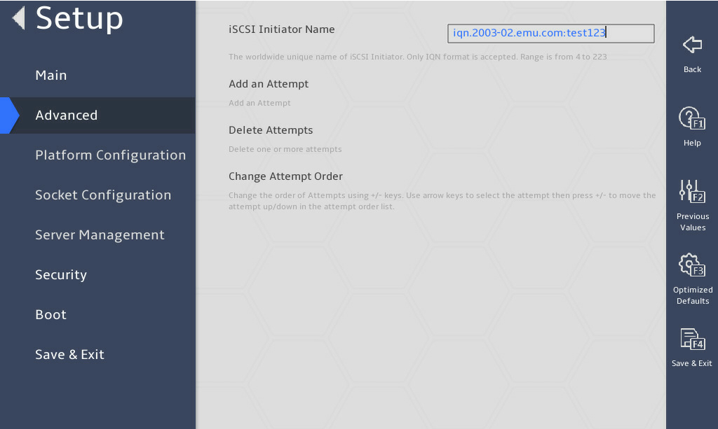
表3-90 Items on the Host iSCSI Configuration submenu screen
|
Item |
Description |
|
iSCSI Initiator Name |
Set the name of the iSCSI initiator. The name is a string of 4 to 223 characters. The name must be in the IQN format of iqn.YYYY-MM.Domain name:Device name. · YYYY—Year. · MM—Month. · Domain name—Domain name in the reversed order. · Device name. For example, iqn.2003-02.emu.com:test123. |
|
Add an Attempt |
Add an iSCSI attempt. |
|
Delete Attempts |
Delete an iSCSI attempt. |
|
Change Attempt Order |
Change the order of the attempts. |
2. Add an Attempt submenu
图3-125 shows the Add an Attempt submenu screen, on which all existing attempts are displayed. Each attempt is identified by the MAC address of an iSCSI Ethernet adapter port. The submenu items for each port are the same.
图3-125 Add an Attempt submenu screen
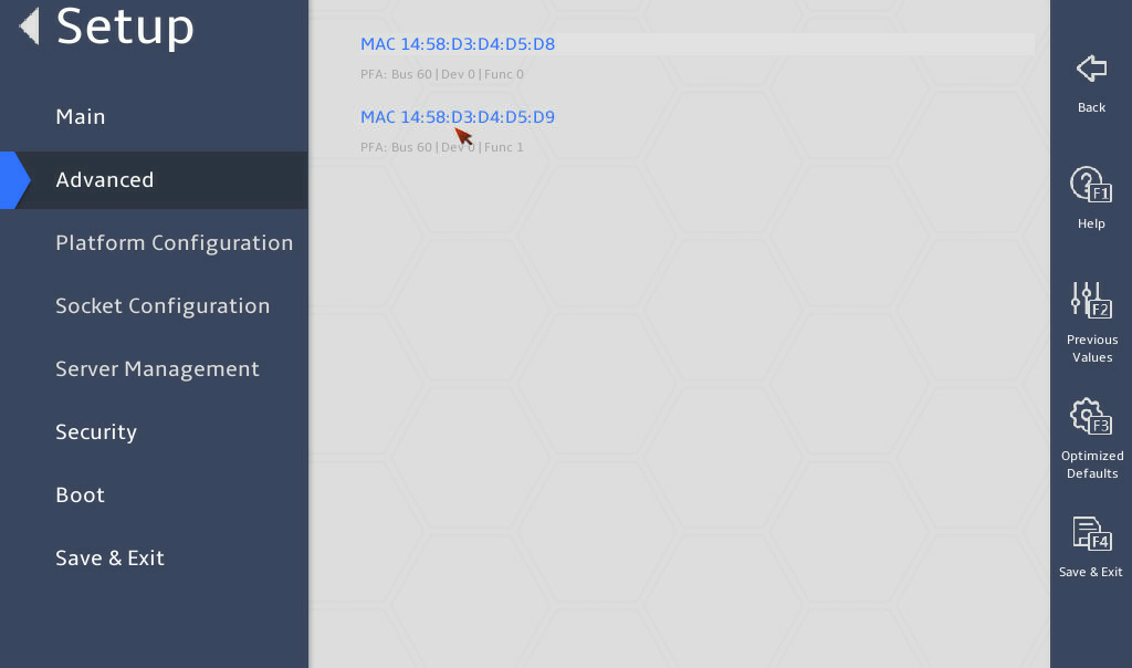
图3-126 shows the submenu for configuring an attempt. The submenu items are described in (2).
图3-126 Attempt Configuration submenu screen
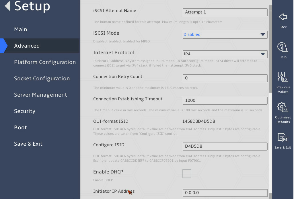
(2) Items on the Attempt Configuration submenu screen
|
Item |
Description |
Default |
|
iSCSI Attempt Name |
Set the name of the iSCSI attempt. The name is a case-sensitive string of 1 to 12 characters. |
N/A |
|
iSCSI Mode |
Set the iSCSI mode. Options: · Disabled—Disables iSCSI. · Enabled—Enables iSCSI. · Enabled for MPIO—Enables MPIO iSCSI. |
Disabled |
|
Internet Protocol |
Select the Internet protocol. Options: · IP4—Enables IPv4. · IP6—Enables IPv6. · Autoconfigure—Configures the Internet protocol automatically. IPv4 takes precedence over IPv6. |
IP4 |
|
Connection Retry Count |
Set the maximum number of connection retries. Value range: 0 to 16. A value of 0 indicates no connection retries. |
N/A |
|
Connection Establishing Timeout |
Set the connection timeout time, in milliseconds. |
1000 |
|
OUT-format ISID |
Displays the ID of the iSCSI initiator. |
N/A |
|
Configure ISID |
Configure the ID of the iSCSI initiator. |
The last six bits in the MAC address of the Ethernet adapter port. |
|
Enable DHCP |
Select Enabled or Disabled to enable or disable DHCP. |
Disabled |
|
Initiator IP Address |
Set the IP address of the iSCSI initiator. |
N/A |
|
Initiator Subnet Mask |
Set the subnet mask of the iSCSI initiator. |
N/A |
|
Gateway |
Set the gateway IP address. |
N/A |
|
Target Name |
Set the name of the iSCSI target. |
N/A |
|
Target Address |
Set the name of the iSCSI target. |
N/A |
|
Target Port |
Set the port number of the iSCSI target. |
3260 |
|
Boot LUN |
Set the LUN of the iSCSI target, in hexadecimal notation. |
N/A |
|
Authentication Type |
Select the authentication type. Options: · None. · CHAP. |
None |
|
CHAP Type |
Select the CHAP authentication type. Options: · Mutual—The iSCSI target and iSCSI initiator authenticate each other. · One way—Only the iSCSI target authenticates the iSCSI initiator. |
Mutual |
|
CHAP Name |
Set the name for CHAP authentication. |
N/A |
|
CHAP Secret |
Set the password for CHAP authentication. |
N/A |
|
CHAP Status |
Displays the status of CHAP authentication. |
N/A |
|
Reverse CHAP Name |
Set the name for reverse CHAP authentication. |
N/A |
|
Reverse CHAP Secret |
Set the password for reverse CHAP authentication. |
N/A |
|
Reverse CHAP Status |
Displays the status of reverse CHAP authentication. |
N/A |
|
Save Changes |
Save the changes. |
N/A |
|
Back to Previous Page |
Return to the previous submenu. |
N/A |
3. Delete Attempts submenu
图3-127 shows the Delete Attempts submenu screen. The items are described in (2).
图3-127 Delete Attempts submenu screen
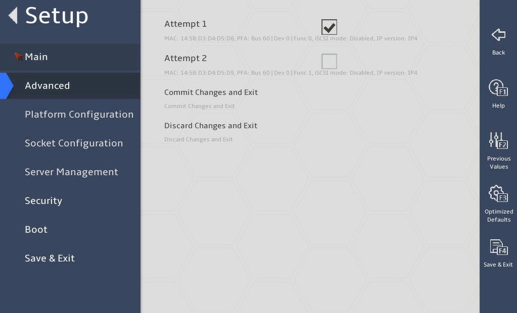
(2) Items on the Delete Attempts submenu screen
|
Item |
Description |
|
Attempt x |
Select the target attempts to delete. |
|
Commit Changes and Exit |
Commit the changes and return to the iSCSI Configuration submenu. |
|
Discard Changes and Exit |
Discard the changes and return to the iSCSI Configuration submenu. |
4. Change Attempt Order submenu
图3-128 shows the Change Attempt Order submenu screen. The items are described in (2).
图3-128 Change Attempt Order submenu screen
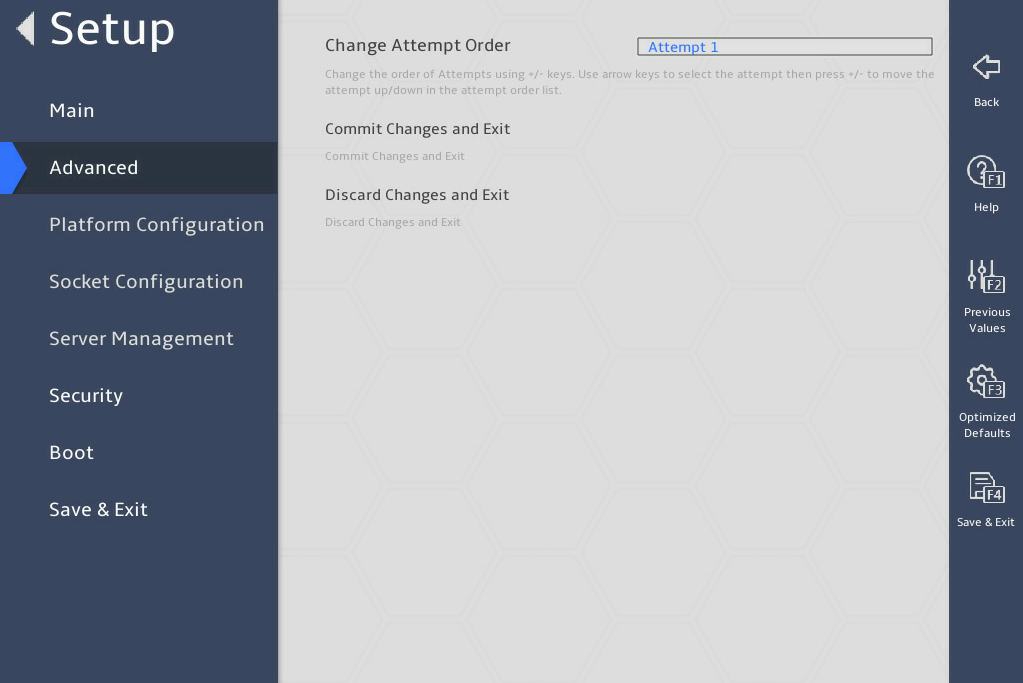
(2) Items on the Change Attempt Order submenu screen
|
Item |
Description |
|
Change Attempt Order |
Change the order of existing attempts. Select an attempt and press + or – key to change its order. |
|
Commit Changes and Exit |
Commit the changes and return to the iSCSI Configuration submenu. |
|
Discard Changes and Exit |
Discard the changes and return to the iSCSI Configuration submenu. |
3.3 Server menu
图3-129 and 图3-130 show the Server menu. From the menu, you can access the firmware information menu, and configure server management features such as the FRB-2 timer, OS watchdog timer, firmware information, HDM network configuration, and HDM user settings.
The menu items are described in 表3-91.
图3-129 Server menu (1)
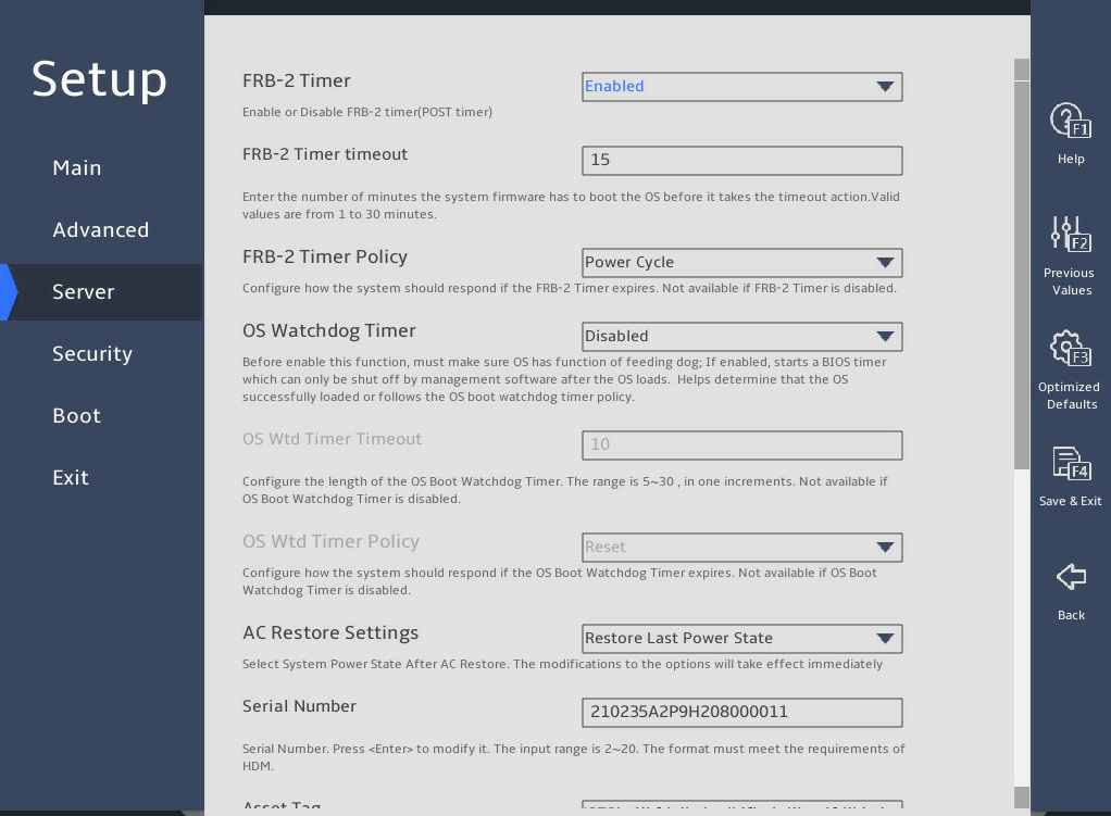
图3-130 Server menu (2)
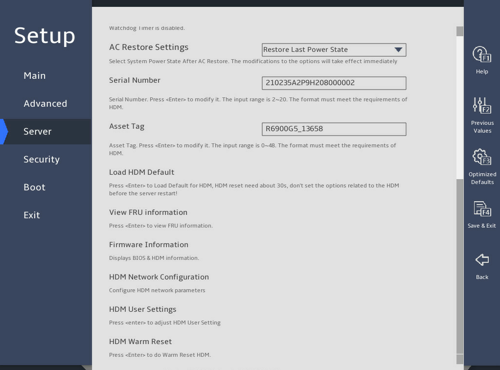
表3-91 Items on the Server menu screen
|
Item |
Description |
Default |
|
FRB-2 Timer |
Select Enabled or Disabled to enable or disable the FRB-2 timer. |
Enabled |
|
FRB-2 Timer timeout |
This item is available only when FRB-2 Timer is set to Enabled. Set the timeout for the FRB-2 timer in the range of 1 to 30 minutes. |
15 minutes |
|
FRB-2 Timer Policy |
This item is available only when FRB-2 Timer is set to Enabled. Select the action to take when the FRB-2 timer expires. Options: · Do Nothing—No action is taken. · Reset—Reboots the system. · Power Down—Removes the main power from the system. · Power Cycle—Power cycles the system. |
Power Cycle |
|
OS Watchdog Timer |
Select Enabled or Disabled to enable or disable the OS watchdog timer. The OS watchdog timer starts when the OS begins to run and restarts the operating system if the system gets stuck. This helps restore the system in case of system crush. |
Disabled |
|
OS Wtd Timer Timeout |
This item is configurable only when OS Watchdog Timer is set to Enabled. Set the timeout for the OS watchdog timer in the range of 5 to 30 minutes. |
10 minutes |
|
OS Wtd Timer Policy |
This item is configurable only when OS Watchdog Timer is set to Enabled. Select the action to take when the OS watchdog timer expires. Options: · Do Nothing—No action is taken. · Reset—Reboot the system. · Power Down—Removes the main power from the system. · Power Cycle—Power cycles the system. |
Reset |
|
AC Restore Settings |
This item is not available for the B5700 G5. Select the state to which the system is restored when the system AC power is restored. Options: · Always Power On—The system always returns to the power-on state. · Always Remain Off—The system always returns to the power-off state. · Restore Last Power State—The system returns to the power state when AC power was lost. The default state also depends on HDM settings. |
Restore Last Power State |
|
Serial Number |
Set the serial number for the server. It is 2-20 characters in length. The format must meet the HDM requirements. |
N/A |
|
Asset Tag |
Set the asses tag for the server. It is 0-48 characters in length. The format must meet the HDM requirements. |
N/A |
|
Load HDM Default |
This item is not available for the B5700 G5. To restore the factory default settings for HDM, select this item, and then press Enter. It takes one minute to restore the factory default HDM settings. After the restoration finishes, the server restarts automatically.
Do not configure HDM-related items before the server restarts. |
N/A |
|
View FRU information |
Access the submenu for viewing FRU information, as shown in 图3-131 and 图3-132. The submenu items are described in 表3-92. |
N/A |
|
Firmware Information |
Access the submenu that displays the firmware information, as shown in 图3-133. The submenu items are described in 表3-93. |
N/A |
|
HDM Network Configuration |
Access the network configuration submenu for HDM access, as shown in 图3-134. The submenu items are described in 表3-94. |
N/A |
|
HDM User Settings |
This item is not available for the B5700 G5. Access the submenu for managing HDM user accounts, as shown in 图3-140. The submenu items are described in 表3-98. |
N/A |
|
HDM Warm Reset |
This item is available only for the R6900 G5. Select to enable HDM warm reset. To perform the HDM warm reset, press Enter and select Yes in the prompt page. |
N/A |
2. View FRU information submenu
图3-131 and 图3-132 show the View FRU information menu screen, on which you can view FRU information. The menu items are described in 表3-92.
图3-131 View FRU information menu screen (1)
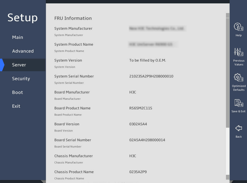
图3-132 View FRU information menu screen (2)
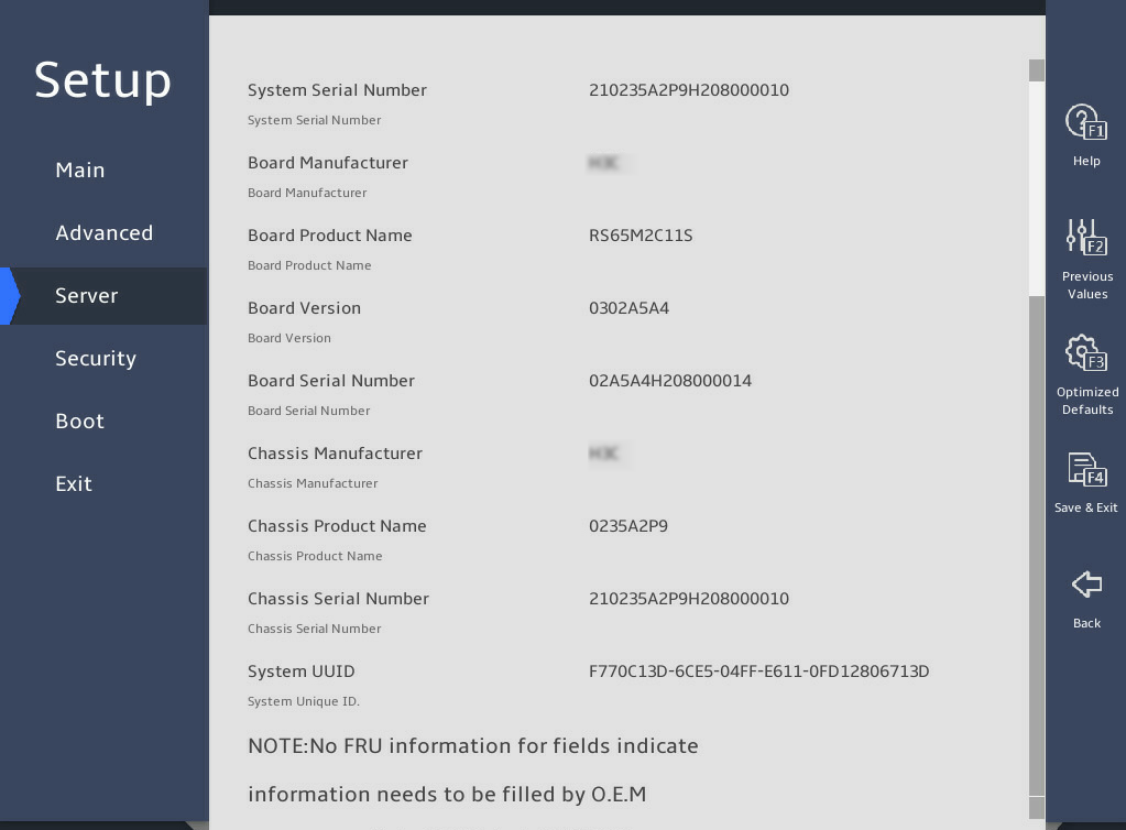
表3-92 Items on the View FRU information menu screen
|
Item |
Description |
|
System Manufacturer |
Displays the manufacturer of the system. |
|
System Product Name |
Displays the name of the system product. |
|
System Version |
Displays the version of the system. |
|
System Serial Number |
Displays the serial number of the system. |
|
Board Manufacturer |
Displays the manufacturer of the system board. |
|
Board Product Name |
Displays the product name of the system board. |
|
Board Version |
Displays the version of the system board. |
|
Board Serial Number |
Displays the serial number of the system board. |
|
Chassis Manufacturer |
Displays the manufacturer of the chassis. |
|
Chassis Product Number |
Displays the product name of the chassis. |
|
Chassis Serial Number |
Displays the serial number of the system product. |
|
System Uuid |
Displays the UUID of the system. |
3. Firmware Information submenu
图3-133 shows the Firmware Information submenu screen, on which you can view firmware information. The menu items are described in 表3-93.
图3-133 Firmware Information submenu screen
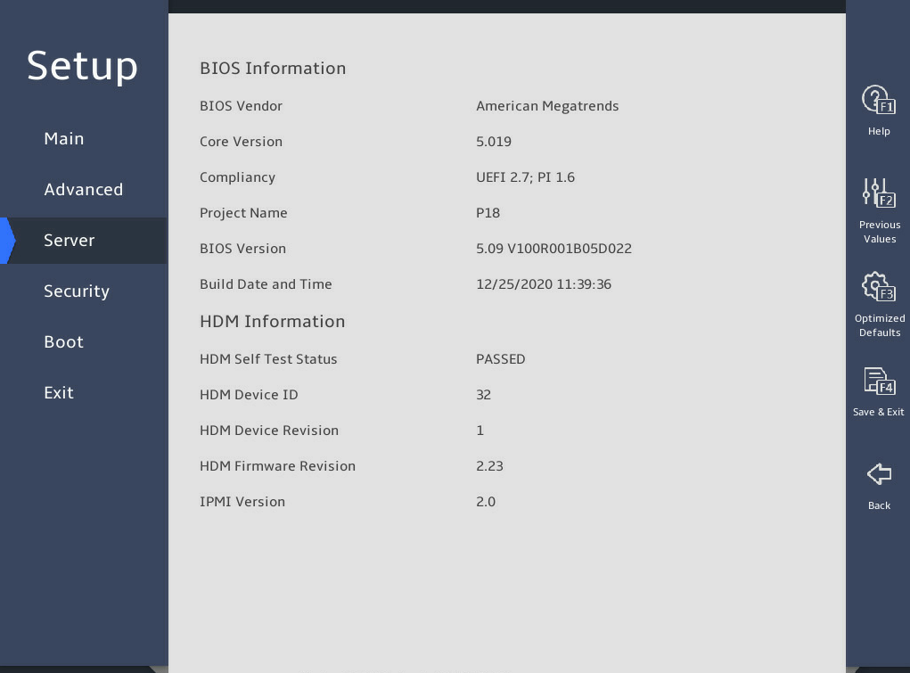
表3-93 Items on the Firmware Information submenu screen
|
Item |
Description |
|
BIOS Information |
|
|
BIOS Vendor |
Displays the BIOS vendor. |
|
Compliancy |
Displays the BIOS compliance standard. |
|
Project Name |
Displays the project name. |
|
BIOS Version |
Displays the BIOS version. |
|
Build Date and Time |
Displays the BIOS build date and time. |
|
HDM Information |
|
|
HDM Self Test Status |
Displays the HDM self test status. |
|
HDM Device ID |
Displays the HDM device ID. |
|
HDM Device Revision |
Displays the HDM device revision. |
|
HDM Firmware Revision |
Displays the HDM firmware revision. |
|
IPMI Version |
Display the IPMI version. |
4. HDM Network Configuration submenu
图3-134 shows the HDM Network Configuration submenu screen, on which you can view HDM network configuration information. The submenu items are described in 表3-94.
图3-134 HDM Network Configuration submenu screen
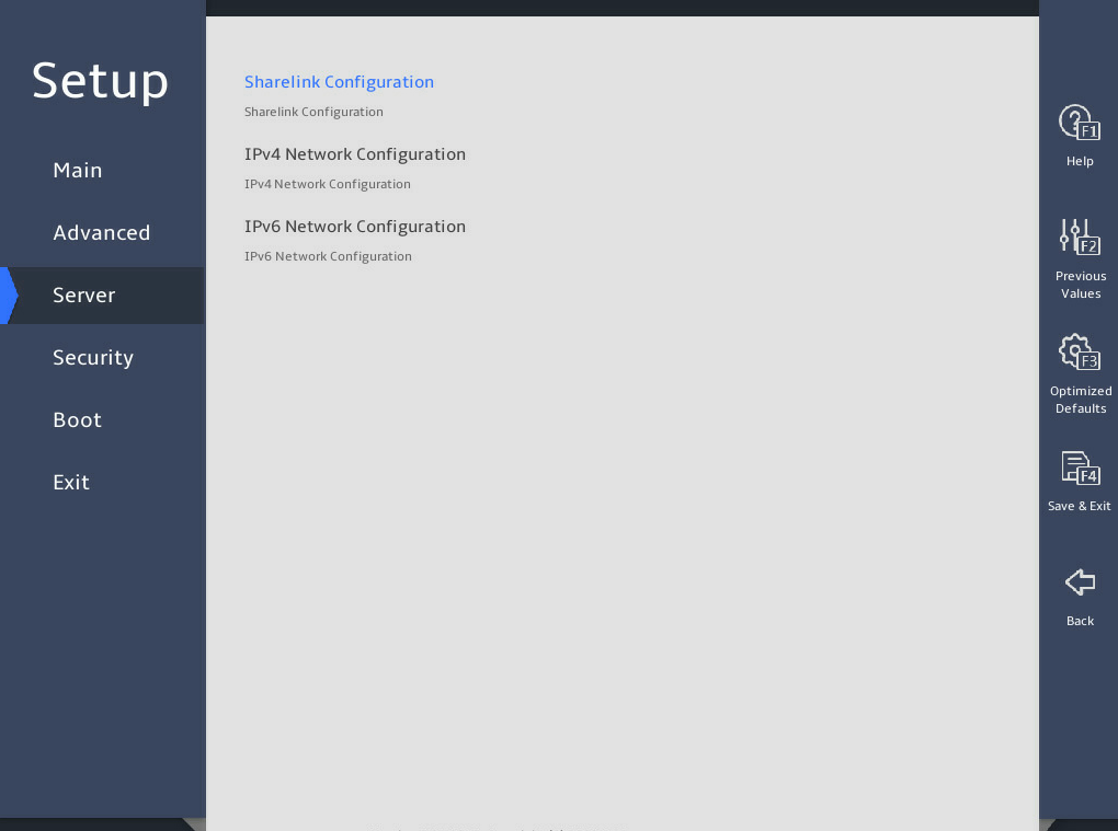
表3-94 Items on the HDM Network Configuration submenu screen
|
Item |
Description |
|
Sharelink Configuration |
This submenu is not available for the B5700 G5. Access the submenu for configuring the HDM sharelink. |
|
IPv4 Network Configuration |
Access the submenu for configuring the IPv4 network. |
|
IPv6 Network Configuration |
Access the submenu for configuring the IPv6 network. |
Sharelink Configuration submenu
图3-135 shows the Sharelink Configuration submenu screen, on which you can view Sharelink configuration information. The submenu items are described in 表3-95.
图3-135 Sharelink Configuration submenu screen
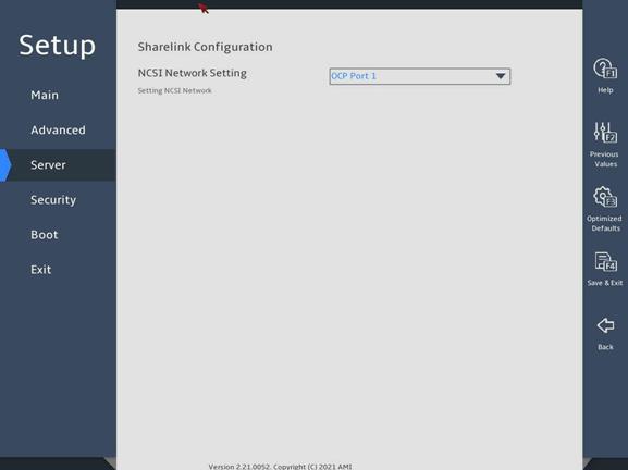
表3-95 Items on the Sharelink Configuration submenu screen
|
Item |
Description |
|
NCSI Network Setting |
Select HDM NCSI network port. This item is available when an NCSI-capable network adapter is installed on the server. You can select any network port of the present NCSI-capable network adapter. |
IPv4 Network Configuration submenu
The HDM shared network port and the HDM dedicated network port have the same parameters. The IP addresses of these ports cannot be in the same segment. The following takes the HDM dedicated network port for example.
图3-136 and 图3-137 show the IPv4 Network Configuration submenu screen, on which you can view IPv4 network configuration information. The menu items are described in 表3-96.
图3-136 IPv4 Network Configuration submenu screen (1)
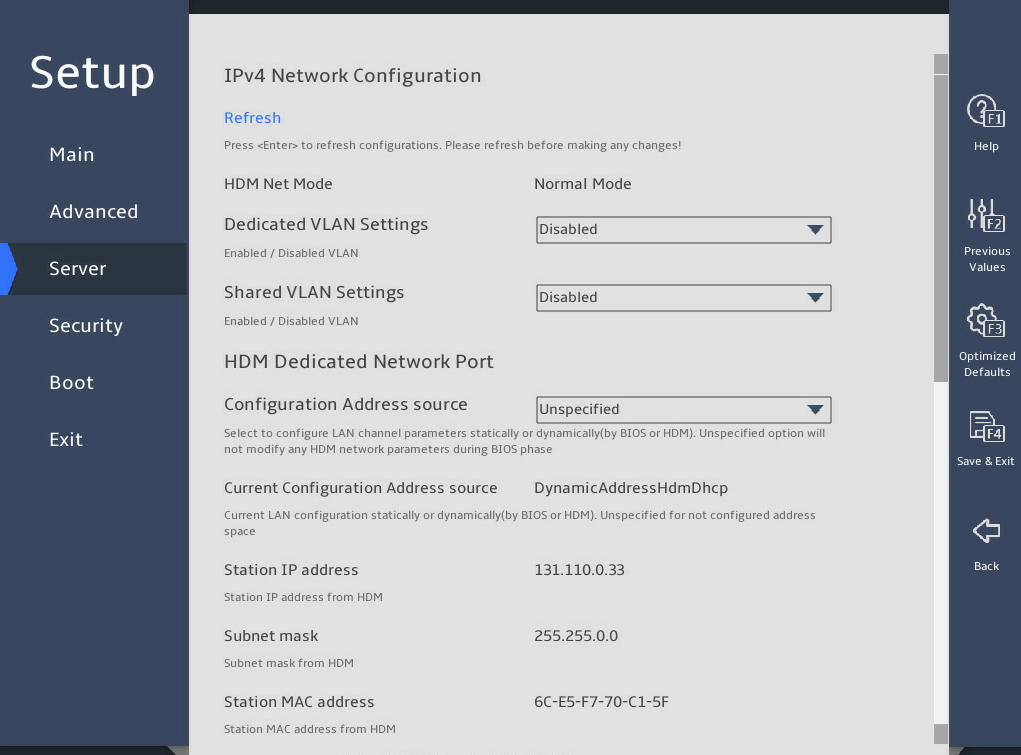
图3-137 IPv4 Network Configuration submenu screen (2)
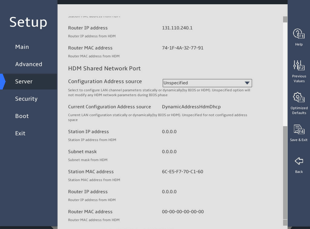
表3-96 Items on the IPv4 Network Configuration submenu screen
|
Item |
Description |
Default |
|
Refresh |
Refresh the HDM network configuration information. Press Enter to refresh configuration before making any changes. |
N/A |
|
HDM Net Mode |
Displays the HDM network mode dynamically. Options: · Normal Mode—In this mode, the HDM can be accessed through the HDM shared network port or the HDM dedicated network port. · Active/standby Mode—In this mode, the HDM dedicated port is used as the first choice to access the HDM. · Bonding Mode—In this mode, the HDM shared network port and the HDM dedicated network port are used as one logical network port. |
N/A |
|
Dedicated VLAN Setting |
Select Enabled or Disabled to enable or disable VLAN on the HDM dedicated network port. |
Disabled |
|
Dedicated VLAN id |
This item is available only when Dedicated VLAN Setting is set to Enabled. Configures the VLAN ID, in the range of 2 to 4094. |
2 |
|
Dedicated VLAN priority |
This item is available only when Dedicated VLAN Setting is set to Enabled. Specify the priority of a dedicated VLAN, in the range of 0 to 7. The larger the number, the higher the priority. When traffic congestion occurs, frames with the highest priority will be sent first. |
0 |
|
Shared VLAN Settings |
Select Enabled or Disabled to enable or disable VLAN on the HDM shared network port. |
Disabled |
|
Shared VLAN id |
This item is available only when Shared VLAN Setting is set to Enabled. Configures the VLAN ID, in the range of 2 to 4094. |
2 |
|
Shared VLAN priority |
This item is available only when Shared VLAN Setting is set to Enabled. Specify the priority of a shared VLAN, in the range of 0 to 7. The larger the number, the higher the priority. When traffic congestion occurs, frames with the highest priority will be sent first. |
0 |
|
HDM Dedicated/Shared Network Port The B5700 G5 displays only HDM dedicated network port information. |
||
|
Configuration Address source |
Configure the HDM network status parameters. Options: · Unspecified—Retains the current configuration. · Static—Uses manually specified configuration. · DynamicHdmDhcp—Uses network information obtained through DHCP. |
Unspecified |
|
Current Configuration Address source |
Displays the current address source. |
N/A |
|
Station IP Address |
This item is available only when Configuration Address source is set to Static. The configured HDM static IPv4 address takes effect only after both the Station IP Address and Subnet Mask are configured. Specify the station IP address for the port. |
192.168.1.2 |
|
Subnet Mask |
This item is available only when Configuration Address source is set to Static. This item must be specified before you set the HDM static IPv4 address. Specify the subnet mask. |
255.255.0.0 |
|
Station MAC Address |
Displays the MAC address of the port. |
N/A |
|
Router IP Address |
This item is available only when Configuration Address source is set to Static. Specify the gateway IP address. |
N/A |
|
Router MAC Address |
Displays the gateway MAC address. |
N/A |
IPv6 Network Configuration submenu
The HDM shared network port and the HDM dedicated network port have the same parameters. The IP addresses of these ports cannot be in the same segment. The following takes the HDM dedicated network port for example.
图3-138 and 图3-139 show the IPv6 Network Configuration submenu screen, on which you can view IPv4 network configuration information. The menu items are described in 表3-97.
图3-138 IPv6 Network Configuration submenu screen (1)
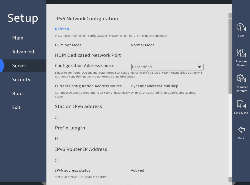
图3-139 IPv6 Network Configuration submenu screen (2)
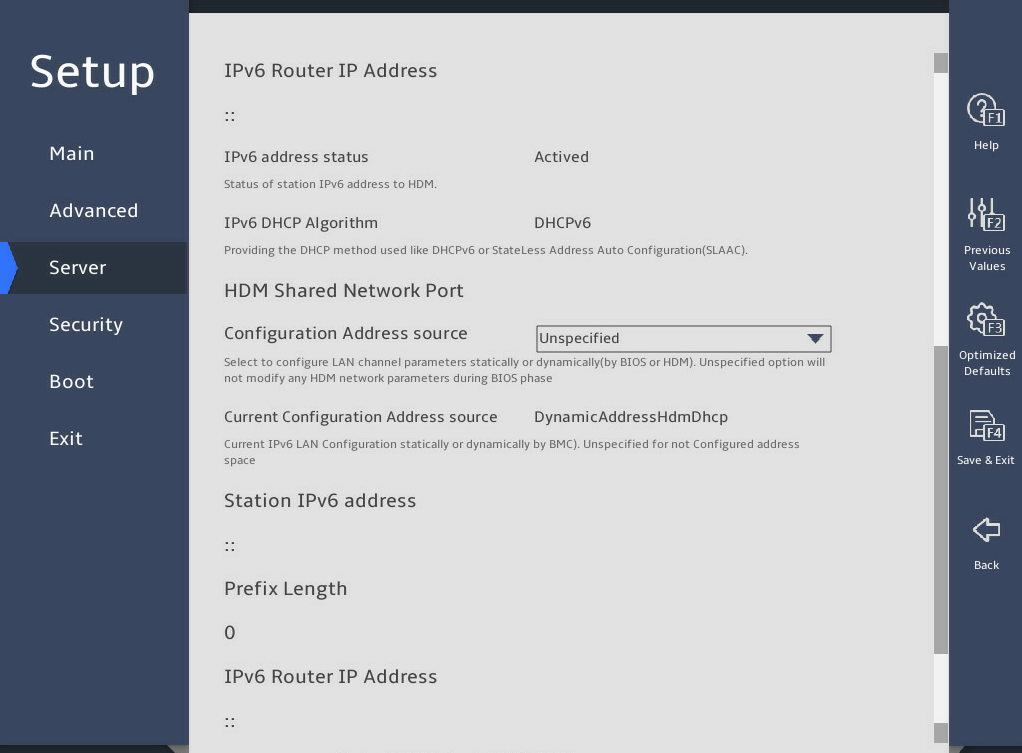
表3-97 Items on the IPv6 Network Configuration submenu screen
|
Item |
Description |
Default |
|
Refresh |
Refresh HDM network configuration information. Press Enter to refresh configuration before making any changes. |
N/A |
|
HDM Net Mode |
Displays the HDM network mode dynamically. Options: · Normal Mode—In this mode, the HDM can be accessed through the HDM shared network port or the HDM dedicated network port. · Active/standby Mode—In this mode, the HDM dedicated port is used as the first choice to access the HDM. · Bonding Mode—In this mode, the HDM shared network port and the HDM dedicated network port are used as one logical network port. |
N/A |
|
HDM Dedicated/Shared Network Port The B5700 G5 displays only HDM dedicated network port information. |
||
|
Configuration Address source |
Configure the HDM network status parameters. Options: · Unspecified—Retains the current configuration. · Static—Uses manually specified configuration. · DynamicHdmDhcp—Uses network information obtained through DHCP. |
Unspecified |
|
Current Configuration Address source |
Displays the current address source. |
N/A |
|
Station IP Address |
This item is available only when Configuration Address source is set to Static. The configured HDM static IPv6 address takes effect only after both the Station IPv6 Address and Prefix Length are configured. Specify the IPv6 address for the port. |
N/A |
|
Prefix Length |
This item is available only when Configuration Address source is set to Static. This item must be specified before you set the HDM static IPv6 address. Specify the prefix length, in the range of 0 to 127. 0 indicates that no prefix length is specified. |
0 |
|
IPv6 Router IP Address |
This item is available only when Configuration Address source is set to Static. The IPv6 gateway IPv6 address and the port IPv6 address must be in the same segment. Specify the IPv6 gateway IP address. |
N/A |
|
IPv6 address status |
Displays the status of the IPv6 address. Options: · Actived. · Disabled. · Pending. · Failed. · Deprecated. · Invalid. · Reserved. |
N/A |
|
IPv6 DHCP Algorithm |
Displays the IPv6 DHCP algorithm. |
N/A |
5. HDM User Settings submenu
图3-140 shows the HDM User Settings menu screen, on which you can configure HDM users. The menu items are described in 表3-98.
This submenu is not available for the B5700 G5.
图3-140 HDM User Settings submenu screen
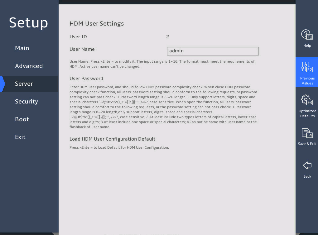
表3-98 Items on the HDM User Settings submenu screen
|
Item |
Description |
Default |
|
User ID |
Displays the current HDM user ID. User information is configurable only when the user ID is 2 (Admin). |
N/A |
|
User Name |
Press Enter to modify the HDM username. A username is a case-sensitive string of 1 to 16 characters and supports only letters, digits, and underscores (_). The name of the login user cannot be modified. |
N/A |
|
User Password |
Set the HDM user password. The password must follow these HDM password complexity check rules: · When password complexity check is enabled: ¡ The password must be a case-sensitive string of 8 to 20 characters and can contain only letters, digits, spaces, and special characters: `~!@#$%^&*()_+-=[]\{}|;':",./<>? ¡ It must contain at least two kinds of characters: uppercase letters, lowercase letters or numbers. ¡ It must contain at least one space or special character. ¡ It cannot be the same as the username or the reverse order of the username. · When password complexity check is disabled, the password must be a case-sensitive string of 2 to 20 characters and can contain only letters, digits, spaces, and the following special characters: `~!@#$%^&*()_+-=[]\{}|;':",./<>? By default, password complexity check is enabled. For more information about how to enable or disable password complexity check, see HDM online help. |
N/A |
|
Load HDM User Configuration |
Restore the default HDM user configuration. If the default HDM user is online, this feature is not available. |
N/A |
3.4 Security menu
图3-141 shows the Security menu, on which you can configure security features such as setting the BIOS administrator and user passwords.
The menu items are described in 表3-99.
图3-141 Security menu screen
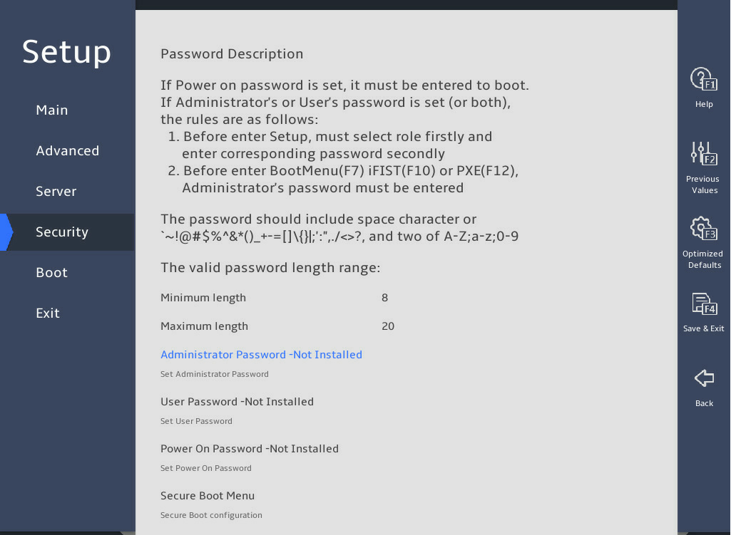
表3-99 Items on the Security menu screen
|
Item |
Description |
|
Password Description |
Displays the password description. |
|
Administrator Password |
Set the administrator password. For more information about restrictions for setting the administrator password, see "Restrictions and guidelines." |
|
User Password |
Set the user password. For more information about restrictions for setting the user password, see "Restrictions and guidelines." |
|
Power On Password |
Set the power-on password. For more information about restrictions for setting the power-on password, see "Restrictions and guidelines." |
|
HDD Security Configuration |
Displays hard disk drives that support security configuration, for example, P2:TS256GMTS800. To configure security settings for a hard disk drive, select the disk drive and press Enter. The screen that opens is as shown in 图3-142, and the submenu items are described in 表3-100. |
|
Secure Boot Menu |
This item is available only in UEFI boot mode. Access the submenu for configuring secure boot, as shown in 图3-143. The submenu items are described in 表3-101. |
图3-142 shows the HDD Security Configuration submenu. The menu items are described in 表3-100.
图3-142 HDD Security Configuration submenu screen
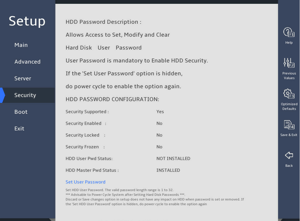
表3-100 Items on the HDD Security Configuration submenu screen
|
Item |
Description |
|
Security Supported |
Displays whether the hard disk drive supports security configuration. |
|
Security Enabled |
Displays whether an HDD user password has been set. If an HDD user password has been set, you must provide the password to unlock the hard disk drive before using it. |
|
Security Locked |
Displays whether the hard disk drive is locked. If the hard disk drive is locked, enter the user password to unlock it. |
|
Security Frozen |
Displays the security frozen status. You cannot format a drive in frozen state. |
|
HDD User Pwd Status |
Displays whether an HDD user password is set. |
|
Set User Password |
Set an HDD user password, 1 to 32 characters in length. If an HDD user password is set or removed, the setting on the BIOS will not affect the password. If this item is inaccessible or hidden, you can power cycle the server for this item to become accessible. |
图3-143 shows the Secure Boot submenu screen. The submenu items are described in 表3-101.
Secure boot is available only in UEFI mode. With this feature enabled, key authentication is required when you load any operating system or hardware driver program. This prevents intrusion of malware. The servers come with a secure boot key and you can import keys as needed. Secure boot does not require any hardware (for example, Trusted Platform Module).
图3-143 Secure Boot submenu screen
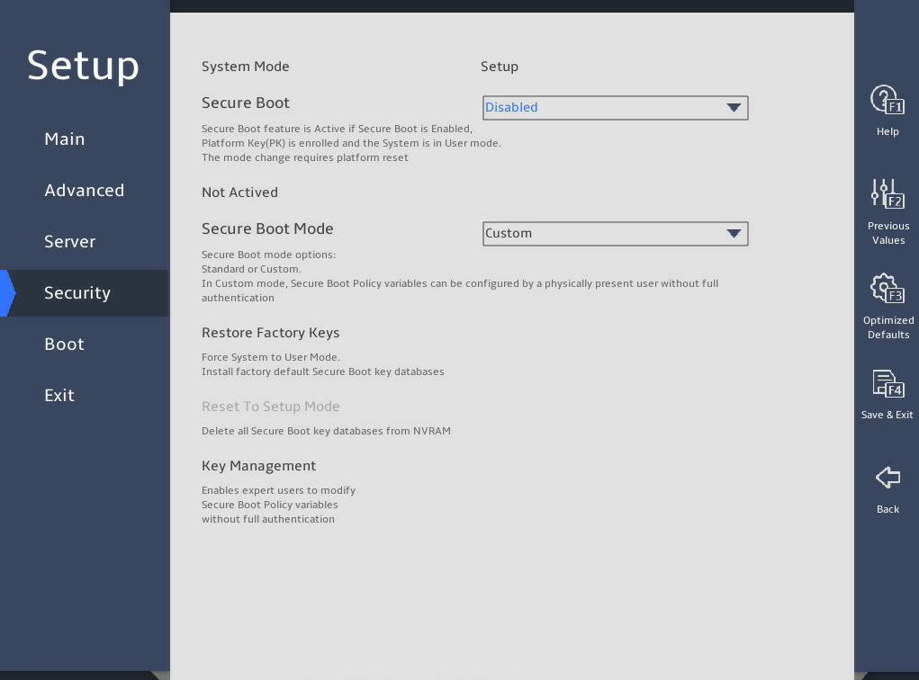
表3-101 Items on the Secure Boot menu screen
|
Item |
Description |
Default |
|
System Mode |
Displays the system mode. |
N/A |
|
Secure Boot |
Select Enabled or Disabled to enable or display secure boot. With this feature enabled, key authentication is required to load any operating system or hardware driver. |
Disabled |
|
Secure Boot Mode |
Select a secure boot mode. Options: · Standard—Uses the preset secure boot key and certificate. In standard boot mode, you can select whether to install the factory default secure boot key, as shown in 图3-144. · Custom—In custom boot mode, you can change the image execution policy and manage secure boot keys. |
Custom |
|
Restore Factory Keys |
Restore the factory default secure boot keys. |
N/A |
|
Reset To Setup Mode |
Reset the system mode to setup mode. |
N/A |
|
Key Management |
Access the submenu for key management, as shown in 图3-145 and 图3-146. The submenu items are described in 表3-102. |
N/A |
图3-144 Installing the factory default secure boot key
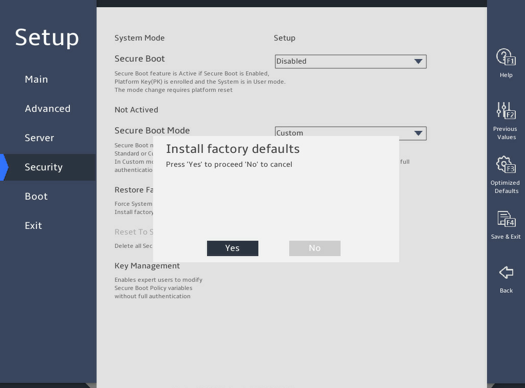
图3-145 and 图3-146 show the Key Management submenu. The submenu items are described in 表3-102.
图3-145 Key Management submenu screen (1)
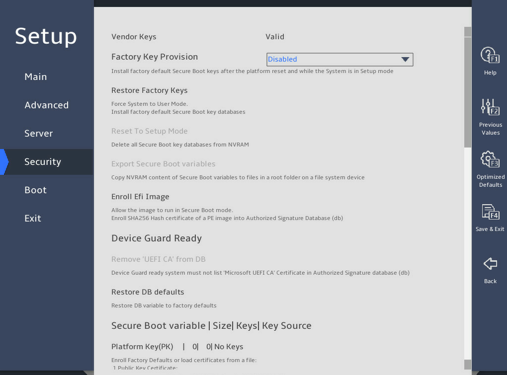
图3-146 Key Management submenu screen (2)
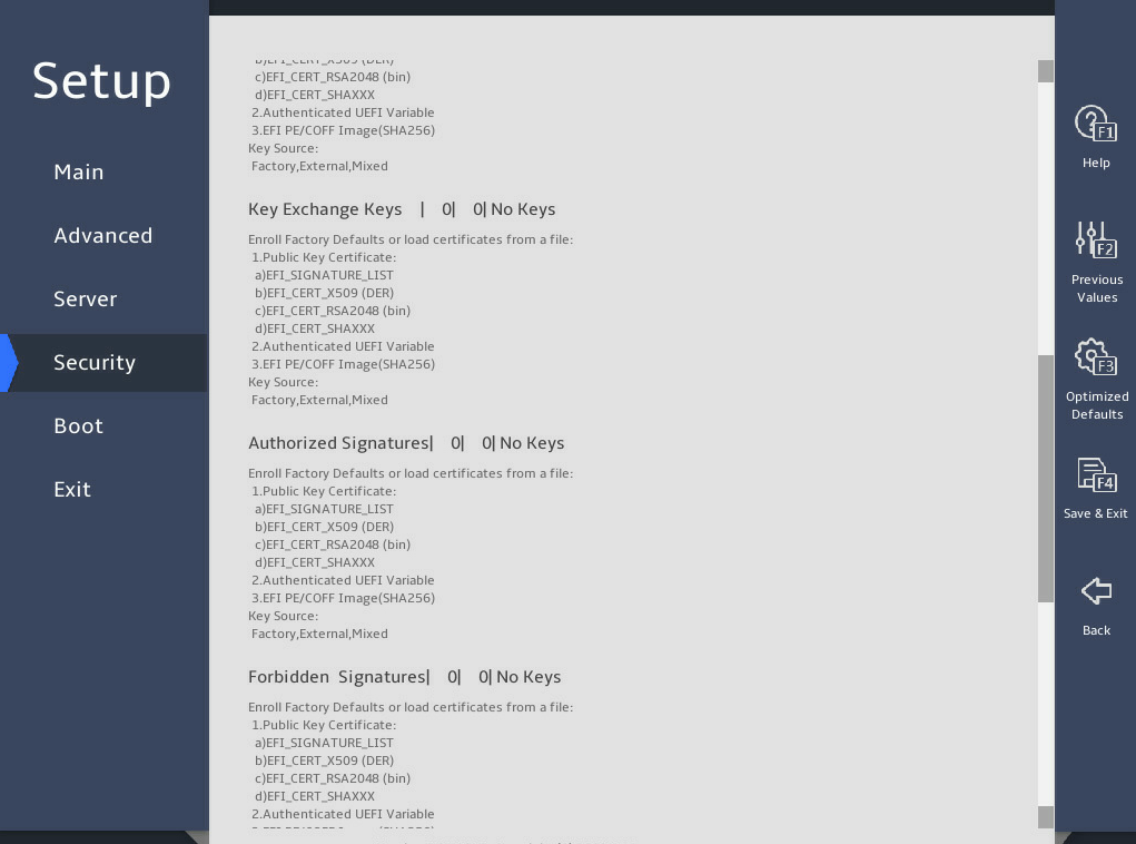
表3-102 Items on the Key Management submenu screen
|
Item |
Description |
Default |
|
Vendor Keys |
Displays whether the vendor keys have been modified. Options: · Valid—The vendor keys have not been modified and are valid. · Modified—The vendor keys have been modified or deleted. |
N/A |
|
Factory Key Provision |
Select Enabled or Disabled to enable or disable provisioning the factory default keys when the system is in setup mode. |
Disabled |
|
Restore Factory Keys |
Access the submenu for restoring factory default keys. This operation forces the system to enter user mode and installs factory default secure boot keys. |
N/A |
|
Reset To Setup Mode |
Access the submenu for resetting the system mode to setup mode. |
N/A |
|
Export Secure Boot Variables |
Access the submenu for exporting all secure boot variables. |
N/A |
|
Enroll Efi Image |
Access the submenu for enrolling the EFI image. This operation enables secure boot for the image and enrolls a SHA256 hash of the PE image in the Authorized Signature Database (DB). |
N/A |
|
Device Guard Ready |
Indicates the server is ready for device guard. |
N/A |
|
Remove ‘UEFI CA’ from DB |
Access the submenu for removing UEFI CA from DB. |
N/A |
|
Restore DB defaults |
Access the submenu for restoring all DB variables to factory defaults. |
N/A |
|
Platform Key(PK) |
Access the submenu for managing the platform key. Option is Update. |
N/A |
|
Key Exchange Keys |
Access the submenu for managing key exchange keys. Options: · Update. · Append. |
N/A |
|
Authorized Signatures |
Access the submenu for configuring authorized signatures. Options: · Update. · Append. |
N/A |
|
Forbidden Signatures |
Access the submenu for managing forbidden signatures. Options: · Update. · Append. |
N/A |
|
Authorized TimeStamps |
Access the submenu for managing authorized timestamps. Options: · Update. · Append. |
N/A |
|
OsRecovery Signatures |
Access the submenu for configuring operating system recovery signatures. Options: · Update. · Append. |
N/A |
3.5 Boot menu
图3-147 and 图3-148 show the Boot menu, on which you can configure boot settings such as the boot type and boot sequence.
The menu items are described in 表3-103.
图3-147 Boot menu screen (1)
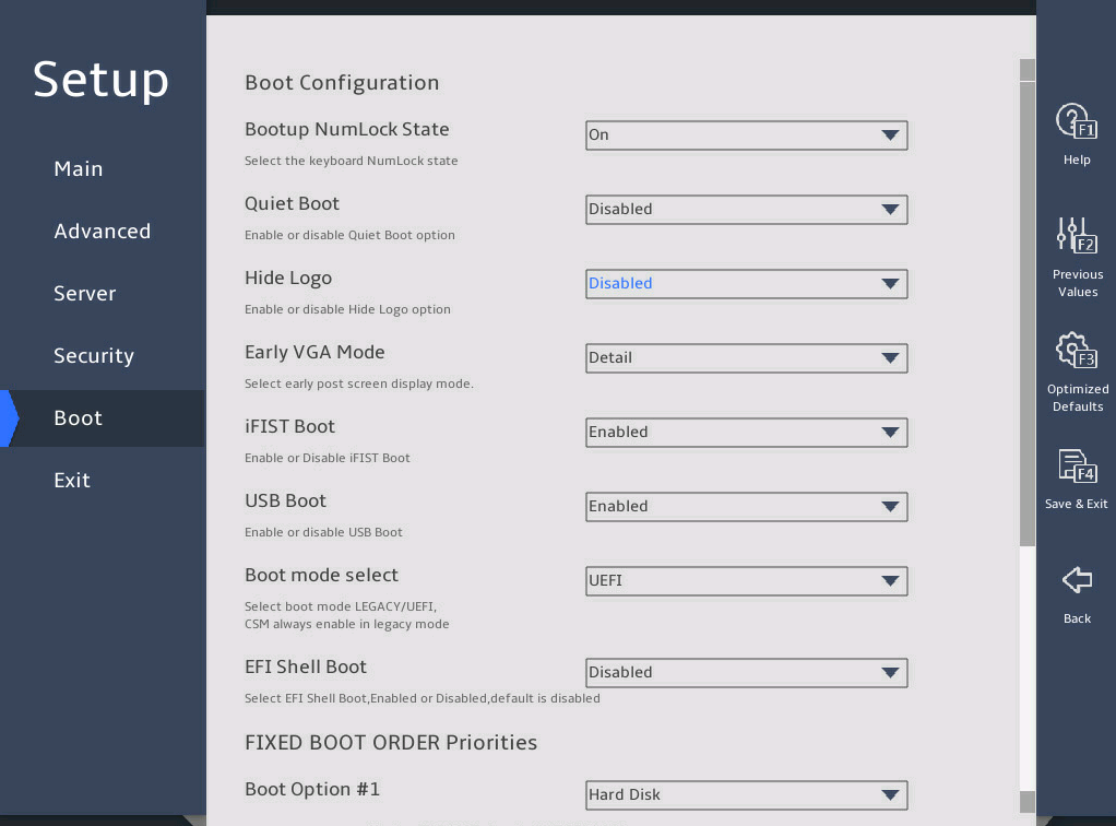
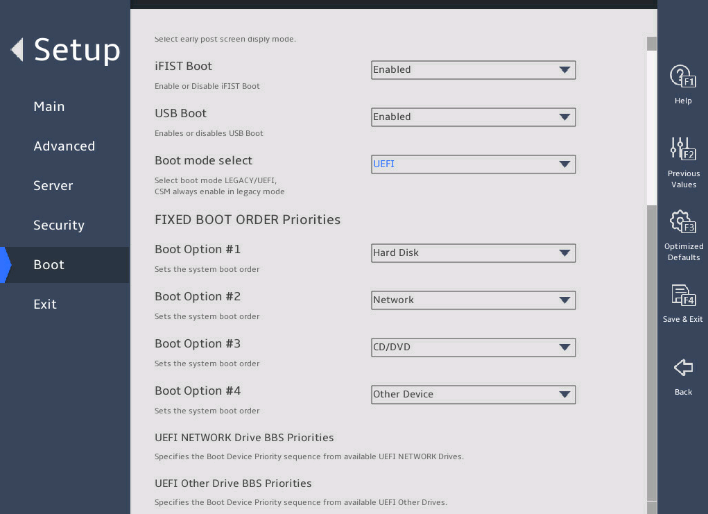
表3-103 Items on the Boot menu screen
|
Item |
Description |
Default |
|
Bootup NumLock State |
Select On or Off to turn on or turn off the NumLock key on the numeric keypad of the keyboard at system boot. |
On |
|
Quiet Boot |
Select On or Off to enable or disable quiet boot mode. Options: · Disabled—Enables the boot screen to display POST information during boot process. · Enabled—Enables the boot screen to display the product logo instead of POST information during boot process. |
Disabled |
|
Hide Logo |
Select Enabled or Disabled to display or hide the logo on the boot screen. |
Disabled |
|
Early VGA Mode |
Displays in the early VGA mode. Options: · Detail—Displays detail information, including logo, version, HDM IP address, progress, and alarm information. · Simple—Displays simple information, including logo, version, and HDM IP address. · LogoOnly—Display the logo only. |
Detail |
|
iFIST Boot |
Select Enabled or Disabled to enable or disable iFIST boot. If iFIST boot is disabled, the iFist item is not displayed on the BIOS startup screen as shown in 图2-1, and pressing F10 cannot boot iFIST. |
Enabled |
|
USB Boot |
Select Enabled or Disabled to enable or disable USB boot. |
Enabled |
|
Boot mode select |
Select a boot mode. Options: · LEGACY. · UEFI. |
UEFI |
|
EFI Shell Boot |
Select Enabled or Disabled to enable or disable shell boot. |
Disabled |
|
Displays the prioritized list of bootable devices from which the system can boot. In legacy mode, a drive is displayed in the list only if it has the highest boot priority (BBS priority) among all the drives of the same type. To display a drive in this list, enter the BBS priorities submenu for the drive type, and then set this drive as the first boot option. |
N/A |
|
|
Boot Option #1 |
Set the first boot option. To disable the first boot option, select Disabled for this item. |
N/A |
|
Boot Option #2 |
Set the second boot option. To disable the second boot option, select Disabled for this item. |
N/A |
|
Boot Option #3 |
Set the third boot option. To disable the third boot option, select Disabled for this item. |
N/A |
|
Boot Option #4 |
Set the fourth boot option. To disable the fourth boot option, select Disabled for this item. |
N/A |
|
UEFI Hard Disk Drive BBS Priorities |
This item is available only in UEFI boot mode. Access the submenu for configuring the boot priorities of hard disk drive, USB-HDD, SD card, and virtual hard disk drive, as shown in 图3-149. The submenu items are described in 表3-104. |
N/A |
|
Hard Disk Drive BBS Priorities |
This item is available only in legacy boot mode. Access the submenu for configuring the boot priorities of hard disk drive, USB-HDD, SD card, and virtual hard disk drive. |
N/A |
|
UEFI CDROM/DVD Drive BBS Priorities |
This item is available only in UEFI boot mode and when one or more CD- or DVD-ROM drives are connected. Access the submenu for configuring the boot priorities of connected CD- or DVD-ROM drives, as shown in 图3-150. The submenu items are described in 表3-105. |
N/A |
|
CDROM/DVD Drive BBS Priorities |
This item is available only in legacy boot mode and when one or more CD- or DVD-ROM drives are connected. Access the submenu for configuring the boot priorities of connected CD- or DVD-ROM drives. |
N/A |
|
UEFI Network Drive BBS Priorities |
This item is available only in UEFI boot mode. Access the submenu for configuring the boot priorities of available network drives, as shown in 图3-151. The submenu items are described in 表3-106. |
N/A |
|
Network Drive BBS Priorities |
This item is available only in legacy boot mode. Access the submenu for configuring the boot priorities of available network drives. |
N/A |
|
UEFI Other Drive BBS Priorities |
Set the boot device priority sequence from the available UEFI other drives. The options include but are not limited to: · Embedded UEFI shell. This option is available only when EFI Shell Boot is set to Enabled. · Other unidentified boot devices. Access the submenu for configuring the boot priorities of other devices, as shown in 图3-152. The submenu items are described in 表3-107. |
N/A |
图3-149 UEFI Hard Disk Drive BBS Priorities submenu screen
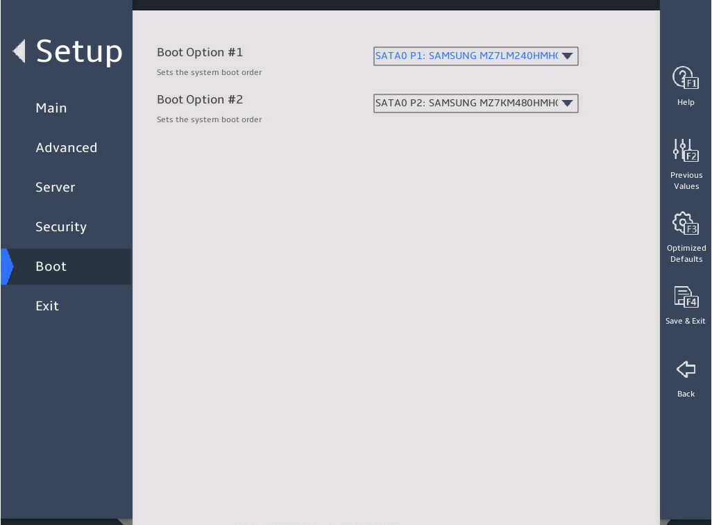
表3-104 Items on the UEFI Hard Disk Drive BBS Priorities submenu screen
|
Item |
Description |
|
Boot Option #1 |
Select a hard disk as the first boot option. To disable this boot option, select Disabled. |
|
The number of available options varies by server configuration. |
|
图3-150 UEFI CDROM/DVD Drive BBS Priorities screen menu
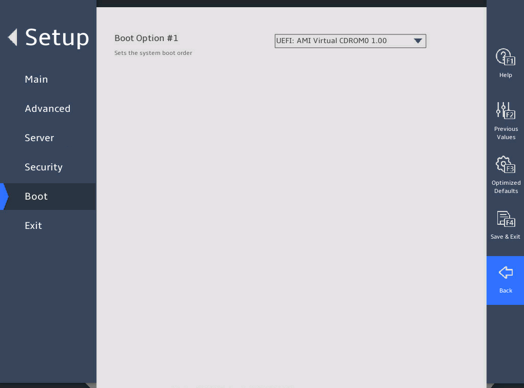
表3-105 Items on the UEFI CDROM/DVD Drive BBS Priorities submenu screen
|
Item |
Description |
|
Boot Option #1 |
Select a CD- or DVD-ROM drive as the first boot option. To disable this boot option, select Disabled. |
|
The number of available options varies by server configuration. |
|
图3-151 UEFI Network Drive BBS Priorities submenu screen

表3-106 Items on the UEFI Network Drive BBS Priorities submenu screen
|
Item |
Description |
|
Boot Option #1 |
Select a PXE boot device as the first boot option. To disable this boot option, select Disabled. |
|
Boot Option #2 |
Select a PXE boot device as the second boot option. To disable this boot option, select Disabled. |
|
The number of available options varies by server configuration. |
|
图3-152 UEFI Other Drive BBS Priorities submenu screen
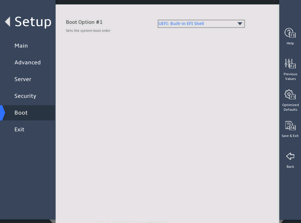
表3-107 Items on the UEFI Other Drive BBS Priorities submenu screen
|
Item |
Description |
|
Boot Option #1 |
Select the other type of boot devices as the first boot option. To disable this boot option, select Disabled. |
|
The number of available options varies by server configuration. |
|
3.6 Exit menu
图3-153 shows the Exit menu, on which you can modify BIOS parameter settings and exit the BIOS.
The menu items are described in 表3-108.
图3-153 Exit menu screen
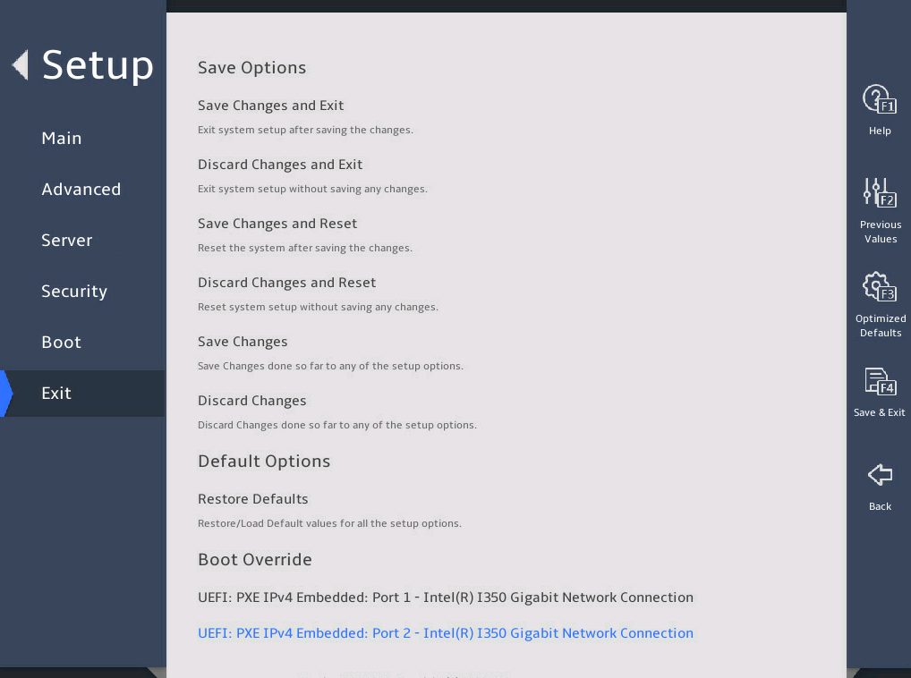
表3-108 Items on the Exit menu screen
|
Item |
Description |
|
Save Options |
|
|
Save Changes and Exit |
Exit with changes saved. |
|
Discard Changes and Exit |
Exit without saving changes. |
|
Save Changes and Reset |
Restart the server with changes saved. (Recommended) |
|
Discard Changes and Reset |
Restart the server without saving changes. |
|
Save Changes |
Save changes without exiting the BIOS. |
|
Discard Changes |
Discard changes without exiting the BIOS. |
|
Default Options |
|
|
Restore Defaults |
Restore the factory-default settings. NOTE: The following information is not restored: · System date and time on the Main screen. · Items except for FRB-2 Timer on the Server screen. · Password-related items on Security screen. |
|
Boot Override |
Select a boot device option and press Enter to boot from that device. This field displays all available boot options. This setting is a one-time setting that takes effect only at the next boot. Subsequent boots will use the boot order configured on the Boot menu screen. |
|
UEFI: PXE IPv4 Embedded: Port x – Intel(R) I350 Gigabit Network Connection |
This item is available only in UEFI boot mode. Select this item as a boot option for one-time boot override. This item is available when port X of the network adapter is connected to an IPv4 PXE server. |
|
IBA 40G Slot 3D00 v1066 |
This item is available only in Legacy boot mode. Select this item as a boot option for one-time boot override. This item is available when port X of the network adapter is connected to an IPv4 PXE server. |
4 Workload profiles (for the R6900 G5 only)
4.1 Introduction
A workload profile is a set of configuration options to deploy BIOS settings for server applications. The BIOS provides several profiles to match the selected workload. You can find the Workload Profile Configuration item from the Advanced > Miscellaneous Configuration screen.
These profiles include:
· General Power Efficient Compute
This profile applies the most common performance settings that benefit most application workloads while also enabling power management settings. In this profile, the CPU core can enter power efficient state, the processor chip can stay in sleep mode, and virtualization is usually disabled.
· General Peak Frequency Compute
This profile is a set of performance-first options. In this profile, power efficient options are disabled to keep all CPU cores staying in C0/C1 state, and virtualization is disabled as well.
· Advanced Reliability Mode
This profile is intended to improve maintainability. With performance policies, the latency for waking up CPU can be reduced, and the response time for system errors can be shortened. As a best practice, use x4 memory chips and enable ADDDC Sparing. If you use x8 memory chips, ADDDC is not supported.
· General Throughput Compute
This profile is intended to be used for workloads where the total maximum sustained workload throughput is needed. Increased throughput can occur when the processor is able to perform sustained work across all available cores during maximum utilization. When SNC is enabled, the average latency to LLC is reduced. Best throughput is achieved when the workload is also nonuniformed memory access (NUMA) aware and optimized.
· High Performance Compute
This profile is intended for clustered environments where each node performs at maximum utilization for extended periods of time to solve large-scale workloads. When virtualization environment is not used, virtualization IO support will be disabled to ensure high performance. Power management is disabled in favor of sustained available bandwidth and processor compute capacity.
· Virtualization-Power Efficient
This profile is intended to be used for virtualization environments. The profile ensures that all available virtualization options are enabled and allows the processor chips to go into sleep state. It is a set of virtualization profile in favor of power efficiency.
· Virtualization–Performance
This profile is intended to be used for virtualization environments to achieve maximum performance. The profile ensures that all available virtualization options are enabled. Power management settings are disabled in favor of delivering maximum performance, and virtual nodes runs at maximum utilization.
· Graphic Processing
This profile is intended for workloads that are run on servers installed with GPUs. GPUs typically depend on maximum bandwidth between I/O and memory. Power management features that have impact on the links between I/O and memory are disabled. Peer to Peer traffic is also critical and therefore virtualization is also disabled.
· Low Latency
This profile is intended to be used in an environment that desires the least amount of computational latency. Maximum speed and throughput are often sacrificed to lower overall computational latency. Power management and other management features that might introduce computational latency are also disabled.
· Transactional Application Processing
This profile is intended to be used for business processing environments, such as online transaction processing (OLTP) applications that require a database back-end. It balances the requirement of managing both peak frequency and throughput.
· Custom
This profile uses the default BIOS settings. You can modify the settings as needed. For information about the default settings, see "BIOS menus."
4.2 Workload profile dependencies matrixes
表4-1 through 表4-2 show the workload profile dependencies matrixes, in which an "X" means that the option setting has no requirement for the profile and can be modified.
Not all the options listed are shown on the BIOS. However, the options of profiles default to the values shown here.
表4-1 Workload profile dependencies matrix
|
Dependency |
General Power Efficient Compute |
General Peak Frequency Compute |
Advanced Reliability Mode |
General Throughput Compute |
High Performance Compute |
|
Hardware Prefetcher |
Enabled |
Enabled |
Enabled |
Enabled |
Enabled |
|
Adjacent Cache Prefetch |
Enabled |
Enabled |
Enabled |
Enabled |
Enabled |
|
DCU Streamer Prefetcher |
Enabled |
Enabled |
Enabled |
Enabled |
Enabled |
|
DCU IP Prefetcher |
Enabled |
Enabled |
Enabled |
Enabled |
Enabled |
|
LLC Prefetch |
X |
X |
X |
Enabled |
X |
|
Extended APIC |
X |
X |
X |
X |
Disabled |
|
VMX |
Disabled |
Disabled |
Disabled |
Disabled |
Disabled |
|
Numa |
Enabled |
Enabled |
Enabled |
Enabled |
Enabled |
|
SNC (Sub NUMA) |
Enabled |
Enabled |
X |
Enabled |
Enabled |
|
XPT Prefetcher |
X |
Enabled |
X |
Enabled |
Enabled |
|
2x Refresh Enable |
X |
Disabled |
X |
Disabled |
Disabled |
|
Patrol Scrub |
Disabled |
Disabled |
X |
X |
Disabled |
|
ADDDC Sparing |
X |
X |
Enabled |
X |
X |
|
Max Rank Interleaving in IMC |
1-way Interleave |
X |
X |
X |
X |
|
Intel VT for Directed I/O (VT-d) |
Disabled |
Disabled |
Disabled |
Disabled |
Disabled |
|
EIST PSD Function |
HW_ALL |
X |
X |
X |
X |
|
Boot performance mode |
Max Efficient |
X |
X |
X |
X |
|
Energy Efficient Turbo |
X |
Disabled |
X |
Disabled |
Disabled |
|
Turbo Mode |
X |
Enabled |
Enabled |
Enabled |
Enabled |
|
Hardware P-States |
Disabled |
Disabled |
X |
X |
Disabled |
|
EPP profile |
Power |
X |
X |
X |
X |
|
CPU C6 report |
Enabled |
X |
Disabled |
X |
Disabled |
|
Enhanced Halt State (C1E) |
Enabled |
X |
Disabled |
X |
Disabled |
|
Enable Monitor MWAIT |
Enabled |
Disabled |
Disabled |
Disabled |
Disabled |
|
Package C State |
C6(Retention) state |
C0/C1 state |
C0/C1 state |
C0/C1 state |
C0/C1 state |
|
Power Performance Tuning |
X |
BIOS Controls EPB |
X |
X |
BIOS Controls EPB |
|
ENERGY_PERF_BIAS_CFG mode |
Power |
Performance |
Performance |
Performance |
Performance |
|
SR-IOV Support |
Disabled |
Disabled |
Disabled |
Disabled |
Disabled |
表4-2 Workload profile dependencies matrix (2)
|
Dependency |
Virtualization-Power Efficient |
Virtualization–Performance |
Graphic Processing |
Low Latency |
Transactional Application Processing |
|
Hardware Prefetcher |
X |
X |
Enabled |
Enabled |
Disabled |
|
Adjacent Cache Prefetch |
X |
X |
Enabled |
Enabled |
Disabled |
|
DCU Streamer Prefetcher |
X |
X |
Enabled |
Enabled |
Disabled |
|
DCU IP Prefetcher |
X |
X |
Enabled |
Enabled |
Disabled |
|
LLC Prefetch |
X |
X |
X |
Enabled |
X |
|
Extended APIC |
X |
X |
Disabled |
Disabled |
X |
|
VMX |
Enabled |
Enabled |
Disabled |
Disabled |
Disabled |
|
Numa |
Enabled |
Enabled |
Enabled |
Enabled |
Enabled |
|
SNC (Sub NUMA) |
Enabled |
Enabled |
X |
Enabled |
X |
|
XPT Prefetcher |
X |
Enabled |
X |
X |
X |
|
2x Refresh Enable |
Disabled |
Disabled |
X |
Disabled |
X |
|
Patrol Scrub |
X |
Disabled |
X |
Disabled |
X |
|
ADDDC Sparing |
X |
X |
X |
X |
X |
|
Max Rank Interleaving in IMC |
1-way Interleave |
X |
X |
X |
X |
|
Intel VT for Directed I/O (VT-d) |
Enabled |
Enabled |
Disabled |
Disabled |
Disabled |
|
EIST PSD Function |
X |
X |
X |
X |
X |
|
Boot performance mode |
X |
X |
X |
X |
X |
|
Energy Efficient Turbo |
X |
Disabled |
X |
Disabled |
Disabled |
|
Turbo Mode |
X |
Enabled |
X |
Disabled |
Enabled |
|
Hardware P-States |
Disabled |
Disabled |
X |
X |
Disabled |
|
EPP profile |
Power |
X |
X |
X |
X |
|
CPU C6 report |
Enabled |
Disabled |
Disabled |
Disabled |
Disabled |
|
Enhanced Halt State (C1E) |
Enabled |
Disabled |
Disabled |
Disabled |
Disabled |
|
Enable Monitor MWAIT |
Enabled |
Disabled |
Disabled |
Disabled |
Disabled |
|
Package C State |
C6(Retention) state |
C0/C1 state |
C0/C1 state |
C0/C1 state |
C0/C1 state |
|
Power Performance Tuning |
X |
BIOS Controls EPB |
BIOS Controls EPB |
X |
X |
|
ENERGY_PERF_BIAS_CFG mode |
Power |
Performance |
Performance |
Performance |
Performance |
|
SR-IOV Support |
Enabled |
Enabled |
Disabled |
Disabled |
Disabled |
5 Acronyms and abbreviations
|
Term |
Definition |
|
A |
|
|
ACPI |
Advanced Configuration and Power Interface |
|
ADR |
Asynchronous Dram Refresh |
|
AHCI |
Advanced Host Controller Interface |
|
B |
|
|
BIOS |
Basic Input Output System |
|
C |
|
|
CFG |
Configure |
|
CSM |
Compatibility Support Module |
|
D |
|
|
DCU |
Drive Control Unit |
|
DMA |
Direct Memory Access |
|
DMI |
Direct Media Interface |
|
DRAM |
Dynamic Random Access Memory |
|
DCPMM |
Intel® OptaneTM DC PMEM module |
|
E |
|
|
ECC |
Error Checking and Correcting |
|
EFI |
Extensible Firmware Interface |
|
EIST |
Enhanced Intel SpeedStep Technology |
|
EMS |
Emergency Management Services |
|
EMCA |
Enhanced Machine Check Architecture |
|
G |
|
|
GPU |
Graphics Processing Unit |
|
H |
|
|
HBA |
Host Bus Adapter |
|
HDM |
Hardware Device Management |
|
I |
|
|
IDE |
Integrated Drive Electronics |
|
IIO |
Integrated I/O Module |
|
IMC |
Integrated Memory Controller |
|
IRQ |
Interrupt Request |
|
iSCSI |
Internet Small Computer System Interface |
|
L |
|
|
LLC |
Last Level Cache |
|
LLDP |
Link Layer Discovery Protocol |
|
LUN |
Logical Unit Number |
|
M |
|
|
MAC |
Media Access Control |
|
MCTP |
Management Component Transport Protocol |
|
ME |
Management Engine |
|
MMIO |
Memory mapping I/O |
|
MRC |
Memory Reference Code |
|
N |
|
|
NIC |
Network Interface Controller |
|
NMI |
Non-Maskable Interrupt |
|
NUMA |
Non Uniform Memory Access |
|
O |
|
|
OS |
Operating System |
|
P |
|
|
PCH |
Platform Controller Hub |
|
PCI |
Peripheral Component Interface |
|
PCIe |
Peripheral Component Interconnect Express |
|
PCU |
Power Controller Unit |
|
PECI |
Platform Environment Control Interface |
|
PMem |
Persistent memory |
|
PK |
Platform Key |
|
POR |
Plan Of Record |
|
POST |
Power On Self Test |
|
PXE |
Preboot Execute Environment |
|
R |
|
|
RAID |
Redundant Arrays of Independent Disks |
|
RAPL |
Running Average Power Limit |
|
RAS |
Reliability, Availability, Serviceability |
|
RFO |
Read For Ownership |
|
ROM |
Read-Only Memory |
|
RTS/CTS |
Request To Send/Clear To Send |
|
S |
|
|
SAS |
Serial Attached SCSI |
|
SATA |
Serial Advanced Technology Attachment |
|
SCSI |
Small Computer System Interface |
|
SEL |
System Event Log |
|
SMI |
System Management Interrupt |
|
SR-IOV |
Single-Root I/O Virtualization |
|
SMBIOS |
System Management BIOS |
|
T |
|
|
TCM |
Trusted Cryptography Module |
|
TDP |
Thermal Design Power |
|
TPM |
Trusted Platform Module |
|
TXT |
Trusted Execution Technologies |
|
U |
|
|
UEFI |
Unified Extensible Firmware Interface |
|
UID |
Unit Identification |
|
UPI |
Ultra Path Interconnect |
|
V |
|
|
VT-d |
Intel Virtualization Technology For Directed I/O |
|
VMD |
Volume Management Device |
|
VGA |
Video Graphics Array |
|
X |
|
|
XHCI |
eXtensible Host Controller Interface |
