- Table of Contents
- Related Documents
-
| Title | Size | Download |
|---|---|---|
| 01-Service chain configuration | 181.62 KB |
Contents
Restrictions and guidelines: Service chain configuration
Configuring an intra-device service chain
Configuring an inter-device service chain
Display and maintenance commands for service chains
Service chain configuration examples
Example: Configuring an intra-device service chain
Example: Configuring an inter-device service chain
Configuring service chains
About service chains
The service chain technology is used to guide network service packets through service nodes. The technology is used in combination with software defined network (SDN) for service orchestration. Service packets in a service chain are forwarded and processed by service nodes in a specific order.
Service chains can be classified into intra-device service chains and inter-device service chains.
Intra-device service chain
Intra-device service chains process IP packets on different types of service modules on a device. The device uses service chain policies to determine whether received IP packets can enter intra-device service chains. Each service chain policy includes an input interface and an ACL. Only the packets that match the ACL can enter the service chain.
Network model
Figure 1 shows the network model of an intra-device service chain. The service chain on the device guides received IP packets through anomaly flow cleaner (AFC) and firewall (FW) nodes in sequence.
Figure 1 Intra-device service chain network diagram
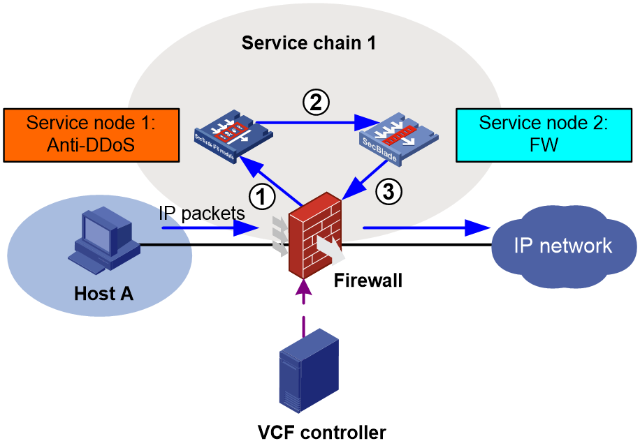
An intra-device service chain includes the following components:
· Service node—Each service node is a group of service modules on the device used to process a specific type of service. An intra-device service chain can contain multiple service nodes. Each service node is assigned a unique number. A service node processes packets based on its service type and the configuration of the load sharing team to which it belongs.
· Load sharing team—A team formed by service modules to load share a specific type of service traffic. Load sharing teams are predefined on the MPUs based on the service types supported by service modules. The device supports only load sharing teams for AFC and FW services. After the service modules start up, the active MPU adds the same type of service modules to the associated team.
Operating mechanisms
The device configured with intra-device service chains uses the policies of the service chains to match packets.
· If the packets match a service chain, the device forwards the packets into that service chain. These packets no longer match the remaining service chains on the device.
· If the packets do not match any service chains, the device forwards the packets according to the routing table.
The device forwards only received IP packets into an intra-device service chain. For locally generated IP packets, the device forwards them according to the routing table.
The device uses the following rules to match received IP packets:
· For packets received on the input interface that is specified in service chain policies, the device compares the packets with these service chains in their configuration order. The packets match a service chain if the source and destination IP addresses in the packets match the source and destination IP addresses in the ACL of the service chain policy, respectively. The matching packets are called forward packets.
· For packets not received on the input interface in service chain policies, the device compares the packets with all service chains in ascending order of service chain numbers. The packets match a service chain if the source and destination IP addresses in the packets match the destination and source IP addresses in the ACL of the service chain policy, respectively. The matching packets are called backward packets.
When the packets enter a service chain, they are processed by all service nodes in either of the following ways:
· Forward packets are guided through the service nodes in ascending order of service node numbers.
· Backward packets are guided through the service nodes in descending order of service node numbers.
After processing, the device forwards the packets to their destinations.
Inter-device service chain
Inter-device service chains apply only to VXLAN packets. Service chain policies are used to control packets in the Overlay network as follows:
1. Encapsulate IP packets into VXLAN packets for service chain processing.
2. Deliver the VXLAN packets through all service nodes in a service chain.
You can deploy service chain policies for different tenant applications from a VCF controller through OpenFlow.
For more information about VXLAN, see VXLAN Configuration Guide. For more information about VCF controllers, see the VCF controller configuration guide.
|
|
NOTE: A service chain applied to contexts of different users on a device is an inter-device service chain. |
Network model
As shown in Figure 2, based on different tenant applications, the VCF controller deploys service chain policies to the service nodes through OpenFlow for the following purposes:
· Match VXLAN packets in the Overlay network. Only matching packets are forwarded into the service chain.
· Make sure the matching packets traverse all service nodes in the service chain.
Figure 2 Inter-device service chain network diagram
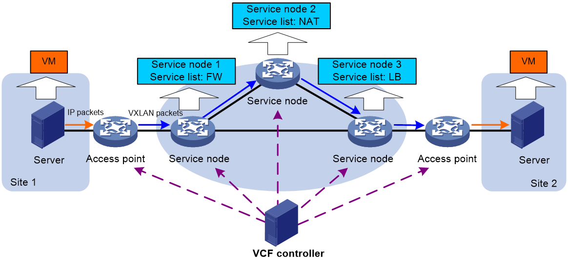
Access point
An access point is a VXLAN tunnel end point (VTEP) that processes packets based on the service chain policy deployed by a VCF controller.
Service node
A service node is a physical device or a network function virtualization (NFV) device that applies services in a service list to the received VXLAN packets. An inter-device service chain can have multiple service nodes.
A service list on a service node specifies the types and order of services to be applied to the VXLAN packets. Available services include FW, LB, ACG, DPI, IPS, IPsec, attack detection and prevention, connection limit, and NAT.
An inter-device service chain supports the following special types of service nodes:
· Head node—The first service node in a service chain that processes the VXLAN packets.
· End node—The last service node in a service chain that processes the VXLAN packets.
Packet format
Inter-device service chain packets use the VXLAN header. Figure 3 shows the format of a service chain packet.
Figure 3 Service chain packet format
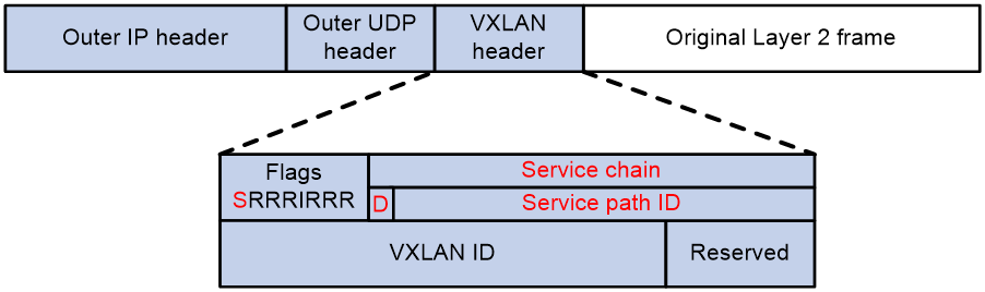
The service chain modifies the following fields in a VXLAN header:
· Flags—If the S bit is 1, the Service chain field is valid. If the S bit is 0, the Service chain field is invalid.
· Service chain—A 24-bit field that includes the D bit and service path ID. If the D bit is 0, the packet is a forward packet. If the D bit is 1, the packet is a backward packet. The 23-bit service path ID is used to identify an inter-device service chain.
Operating mechanisms
An inter-device service chain processes a packet in the following procedure:
1. Based on the service chain policy deployed from the VCF controller, the access point in the inbound packet direction (inbound access point) processes the received packet as follows:
a. Encapsulates the packet into a VXLAN packet.
b. Forwards the VXLAN packet to the head node.
2. The head node compares the service path ID in the VXLAN header of the received packet with the path IDs of the service chains.
¡ If the packet matches a service chain, the head node forwards the packet into the service chain.
¡ If the packet does not match any service chain, the head node performs a VXLAN forwarding for the packet.
3. After a service node completes processing the received VXLAN packet, it forwards the packet in one of the following ways:
¡ If the IP address of the next service node is specified, the node forwards the packet to the next service node.
¡ If no next service node address is specified, the current service node is the end node. The service node removes the service path ID field from the packet and forwards the packet to the access point in the outbound packet direction (outbound access point).
4. The outbound access point decapsulates the VXLAN packet and performs an IP forwarding for the packet.
Restrictions and guidelines: Service chain configuration
Service chains are supported only on non-default contexts. You cannot deploy service chains on the default context.
Configuring an intra-device service chain
Restrictions and guidelines
A load sharing team can be specified only for one service chain.
The service modules on one service chain must belong to the same security engine group. For more information about security engine groups, see context configuration in Virtual Technologies Configuration Guide.
The AFC load sharing team must be configured on service node 1. The firewall load sharing team must be configured on service node 2.
The AFC service modules in an intra-device service chain do not have Layer 2 or Layer 3 forwarding capabilities.
Procedure
1. Enter system view.
system-view
2. Create a service chain and enter its view.
service-chain path path-id
3. Configure a service chain policy for the service chain.
if-match input-interface interface-type interface-number acl { ipv4-acl-number | name ipv4-acl-name }
By default, no service chain policies are configured for an intra-device service chain.
This command takes effect only on IPv4 packets forwarded by the device.
4. Create a service node and enter its view.
service function function-id
5. Specify a load sharing team.
blade-load-balance-team team-name
By default, no load sharing team is specified.
Configuring an inter-device service chain
You can configure an inter-device service chain through VCF controller deployment or at the CLI. This document describes inter-device service chain configuration at the CLI. As a best practice, use a VCF controller to deploy the service chain configuration through a NETCONF session. For more information about the VCF controller deployment method, see the VCF controller configuration guide.
Configuring an access point
You can only use a VCF controller to deploy the service chain configuration to a device that acts as an access point. For more information, see the relevant VCF controller manuals.
Configuring a service node
Restrictions and guidelines
If the device is the end node in an inter-device service chain, you only need to specify the previous service node address.
If the device is the head node in an inter-device service chain, you only need to specify the next service node address.
Procedure
1. Enter system view.
system-view
2. Create a service chain and enter its view.
service-chain path path-id
3. Specify the next service node address for forward packets.
next-service-node ip-address
By default, no next service node address is specified for forward packets.
4. Specify the previous service node address for backward packets.
previous-service-node ip-address
By default, no previous service node address is specified for backward packets.
5. Create a service node and enter its view.
service function function-id
6. Configure a service list.
service list { acg | atk | connect-limit | dpi | fw | ips | ipsec | lb | nat } *
Display and maintenance commands for service chains
Execute display commands in any view.
|
Command |
|
|
Display IPv4 fast forwarding entries for intra-device service chains. |
In standalone mode: display service-chain cache ip [ ip-address ] [ slot slot-number cpu cpu-number ] In IRF mode: display service-chain cache ip [ ip-address ] [ chassis chassis-number slot slot-number cpu cpu-number ] |
|
Display fast forwarding entries of fragments for intra-device service chains. |
In standalone mode: display service-chain cache ip fragment [ ip-address ] [ slot slot-number cpu cpu-number ] In IRF mode: display service-chain cache ip fragment [ ip-address ] [ chassis chassis-number slot slot-number cpu cpu-number ] |
|
Display IPv6 fast forwarding entries for intra-device service chains. |
In standalone mode: display service-chain cache ipv6 [ ipv6-address ] [ slot slot-number cpu cpu-number ] In IRF mode: display service-chain cache ipv6 [ ipv6-address ] [ chassis chassis-number slot slot-number cpu cpu-number ] |
|
Display service chain information. |
display service-chain path { path-id | all } |
|
Display service chain statistics. |
display service-chain statistics |
Service chain configuration examples
Example: Configuring an intra-device service chain
Network configuration
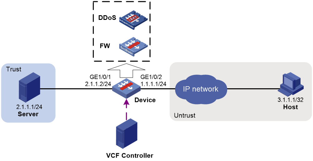
As shown in Figure 4, an AFC module and an FW module are installed in the device. Configure an intra-device service chain on the device to apply AFC and FW services in sequence to the packets from the host to the server.
Procedure
1. Assign IP addresses to interfaces:
# Assign an IP address to interface GigabitEthernet 1/0/1.
<Device> system-view
[Device] interface gigabitethernet 1/0/1
[Device-GigabitEthernet1/0/1] ip address 2.1.1.2 24
[Device-GigabitEthernet1/0/1] quit
# Assign IP addresses to other interfaces in the same way. (Details not shown.)
2. Add interfaces to security zones.
[Device] security-zone name trust
[Device-security-zone-Trust] import interface gigabitethernet 1/0/1
[Device-security-zone-Trust] quit
[Device] security-zone name untrust
[Device-security-zone-Untrust] import interface gigabitethernet 1/0/2
[Device-security-zone-Untrust] quit
3. Configure a security policy:
# Configure a rule named untrust-trust to permit the packets from Host to Server.
[Device] security-policy ip
[Device-security-policy-ip] rule name untrust-trust
[Device-security-policy-ip-1-untrust-trust] source-zone untrust
[Device-security-policy-ip-1-untrust-trust] destination-zone trust
[Device-security-policy-ip-1-untrust-trust] source-ip-host 3.1.1.1
[Device-security-policy-ip-1-untrust-trust] destination-ip-host 2.1.1.1
[Device-security-policy-ip-1-untrust-trust] action pass
[Device-security-policy-ip-1-untrust-trust] quit
[Device-security-policy-ip] quit
4. Configure service chain settings:
# Configure advanced ACL 3000 to permit packets from the host and destined for the server.
[Device] acl advanced 3000
[Device-acl-ipv4-adv-3000] rule permit ip source 3.1.1.1 0.0.0.255 destination 2.1.1.1 0
[Device-acl-ipv4-adv-3000] quit
# Create intra-device service chain 1 and enter its view.
[Device] service-chain path 1
# Configure a policy to direct packets from the host to the service chain by specifying input interface GigabitEthernet 1/70/2 and ACL 3000.
[Device-spath1] if-match input-interface gigabitethernet 1/7/0/2 acl 3000
# Create service nodes. Make sure the load sharing team is the AFC module for service node 1, and is the firewall module for service node 2.
[Device-spath1] service function 1
[Device-spath1-func1] blade-load-balance-team AFC
[Device-spath1-func1] quit
[Device-spath1] service function 2
[Device-spath1-func2] blade-load-balance-team Blade4fw
Verifying the configuration
# Verify that packets from the host to the server enter service chain 1, and the service chain provides AFC and FW services in sequence for the packets. (Details not shown.)
Example: Configuring an inter-device service chain
Network configuration
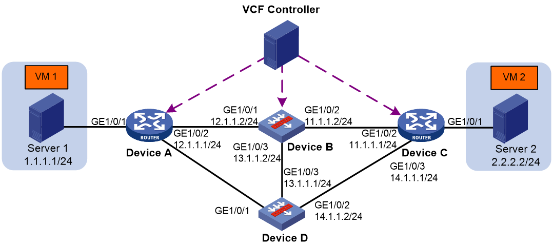
As shown in Figure 5, Device A and Device C act as access points. Device B and Device D act as service nodes. VM 1 and VM 2 are internal network devices. The inter-device service chain processes the traffic from VM 1 to VM 2 as follows:
1. On Device B, apply the FW service to the traffic.
2. On Device D, apply the LB service to the traffic.
Procedure
1. Configure IP addresses for interfaces to ensure IP connectivity between neighboring nodes. (Details not shown.)
2. Use a VCF controller to deploy service chain policies to Device A and Device C and label the VXLAN packets from VM 1 to VM 2 with service path ID 1. (Details not shown.)
3. Configure Device B:
a. Assign IP addresses to interfaces:
# Assign an IP address to interface GigabitEthernet 1/0/1.
<DeviceB> system-view
[DeviceB] interface gigabitethernet 1/0/1
[DeviceB-GigabitEthernet1/0/1] ip address 12.1.1.2 24
[DeviceB-GigabitEthernet1/0/1] quit
# Assign IP addresses to other interfaces in the same way. (Details not shown.)
b. Add interfaces to security zones.
[DeviceB] security-zone name trust
[DeviceB-security-zone-Trust] import interface gigabitethernet 1/0/1
[DeviceB-security-zone-Trust] import interface gigabitethernet 1/0/2
[DeviceB-security-zone-Trust] import interface gigabitethernet 1/0/3
[DeviceB-security-zone-Trust] quit
c. Configure settings for routing.
This example configures a static route, and the next hop in the route is 12.1.1.1.
[DeviceB] ip route-static 1.1.1.0 24 12.1.1.1
d. Configure a security policy:
# Configure a rule named trust-trust to permit the packets from VM 1 to VM 2.
[DeviceB] security-policy ip
[DeviceB-security-policy-ip] rule name trust-trust
[DeviceB-security-policy-ip-1-trust-untrust] source-zone trust
[DeviceB-security-policy-ip-1-trust-untrust] destination-zone trust
[DeviceB-security-policy-ip-1-trust-untrust] source-ip-subnet 1.1.1.0 24
[DeviceB-security-policy-ip-1-trust-untrust] destination-ip-subnet 2.2.2.0 24
[DeviceB-security-policy-ip-1-trust-untrust] action pass
[DeviceB-security-policy-ip-1-trust-untrust] quit
[DeviceB-security-policy-ip] quit
e. Configure service chain settings:
# Create service chain 1 and enter its view.
[DeviceB] service-chain path 1
# Specify the next service node address as 20.1.1.1, which is the loopback interface address of Device D. The loopback interface is specified as the VXLAN tunnel source interface.
[DeviceB-spath1] next-service-node 20.1.1.1
# Create service node 1.
[DeviceB-spath1] service function 1
# Create a service list that includes the FW service.
[DeviceB-spath1-func1] service list fw
4. Configure Device D:
a. Assign IP addresses to interfaces:
# Assign an IP address to interface GigabitEthernet 1/0/2.
<DeviceD> system-view
[DeviceD] interface gigabitethernet 1/0/2
[DeviceD-GigabitEthernet1/0/2] ip address 14.1.1.2 24
[DeviceD-GigabitEthernet1/0/2] quit
# Assign IP addresses to other interfaces in the same way. (Details not shown.)
b. Add interfaces to security zones.
[DeviceD] security-zone name trust
[DeviceD-security-zone-Trust] import interface gigabitethernet 1/0/2
[DeviceD-security-zone-Trust] import interface gigabitethernet 1/0/3
[DeviceD-security-zone-Trust] quit
c. Configure settings for routing.
This example configures a static route, and the next hop in the route is 14.1.1.1.
[DeviceD] ip route-static 2.2.2.0 24 14.1.1.1
d. Configure a security policy:
# Configure a rule named trust-trust to permit the packets from VM 1 to VM 2.
[DeviceD] security-policy ip
[DeviceD-security-policy-ip] rule name trust-trust
[DeviceD-security-policy-ip-1-trust-untrust] source-zone trust
[DeviceD-security-policy-ip-1-trust-untrust] destination-zone trust
[DeviceD-security-policy-ip-1-trust-untrust] source-ip-subnet 1.1.1.0 24
[DeviceD-security-policy-ip-1-trust-untrust] destination-ip-subnet 2.2.2.0 24
[DeviceD-security-policy-ip-1-trust-untrust] action pass
[DeviceD-security-policy-ip-1-trust-untrust] quit
[DeviceD-security-policy-ip] quit
e. Configure service chain settings:
# Create service chain 1 and enter its view..
[DeviceD] service-chain path 1
# Specify the previous service node address as 20.1.1.2, which is the loopback interface address of Device B. The loopback interface is specified as the VXLAN tunnel source interface.
[DeviceD-spath1] previous-service-node 20.1.1.2
# Create service node 1.
[DeviceD-spath1] service function 1
# Create a service list that includes the LB service.
[DeviceD-spath1-func1] service list lb
Verifying the configuration
# Verify the following information: (Details not shown.)
· VXLAN packets from VM 1 to VM 2 are labeled with the path ID of the service chain.
· The FW and LB services are applied to the packets in sequential order.
