- Table of Contents
- Related Documents
-
| Title | Size | Download |
|---|---|---|
| 01-NAT configuration | 1.01 MB |
Contents
Restrictions: Hardware compatibility with NAT
Destination address translation
Device access with overlapping addresses
Configuring outbound bidirectional NAT for internal-to-external access through domain name
Configuring the global NAT policy
Restrictions and guidelines for global NAT policy configuration
Creating the global NAT policy
Rearranging NAT rules in the policy to adjust their priority
Configuring the HA group for NAT
Configuring the active/standby mode
Configuring the dual-active mode
Configuring NAT in specific networks
Enabling NAT reply redirection
Enabling the deletion of timestamps in TCP SYN and SYN ACK packets
Configuring periodic NAT statistics collection
Enabling statistics collection for NAT session creation rate
Specifying a probe method for detecting reachability of NAT address group members
Enabling sending ICMP error messages for NAT failures
Configuring NAT session logging
Configuring NAT444 user logging
Enabling logging for IP usage of a NAT address group in NO-PAT mode
Display and maintenance commands for global NAT
Global NAT configuration examples
Example: Configuring outbound one-to-one static NAT
Example: Configuring outbound dynamic NAT (non-overlapping addresses)
Example: Configuring NAT Server for external-to-internal access
Example: Configuring NAT hairpin in P2P mode
Example: Configuring the global NAT policy for NAT444 dynamic port mapping
Configuring interface-based NAT
Restrictions and guidelines: interface-based NAT configuration
Interface-based NAT tasks at a glance
Configuring static NAT on an interface
Restrictions and guidelines for static NAT configuration on an interface
Configuring outbound one-to-one static NAT
Configuring outbound net-to-net static NAT
Configuring object group-based outbound static NAT
Configuring inbound one-to-one static NAT
Configuring inbound net-to-net static NAT
Configuring object group-based inbound static NAT
Configuring dynamic NAT on an interface
Restrictions and guidelines dynamic NAT configuration on an interface
Configuring outbound dynamic NAT
Configuring inbound dynamic NAT
Configuring NAT server mappings on an interface
Restrictions and guidelines for NAT server mapping configuration on an interface
Configuring common NAT server mappings
Configuring load sharing NAT server mappings
Configuring ACL-based NAT server mappings
Configuring object group-based NAT server mappings
Configuring NAT444 on an interface
Restrictions and guidelines for NAT444 configuration on an interface
Configuring static port block mapping for NAT444
Configuring dynamic port block mapping for NAT444
Enabling port block global sharing
Configuring DS-Lite B4 address translation on an interface
Configuring the interface-based NAT policy
About the interface-based NAT policy
Restrictions and guidelines for interface-based NAT policy configuration
Creating the interface-based NAT policy
Rearranging NAT rules in the policy to adjust their priority
Using failover groups for dynamic NAT
About using failover groups for dynamic NAT
Restrictions and guidelines for using a failover group
Specifying a failover group for a NAT address group
Specifying a failover group for Easy IP
Specifying a port range for a failover group to implement Easy IP
Redistributing NAT load on service engines
Enabling dynamic NAT load sharing
Enabling static NAT load sharing
Specifying a load sharing group for NAT
Configuring the active/standby mode
Configuring the dual-active mode
Configuring periodic NAT statistics collection
Enabling statistics collection for NAT session creation rate
Specifying a probe method for detecting reachability of NAT address group members
Enabling sending ICMP error messages for NAT failures
Configuring NAT session logging
Configuring NAT444 user logging
Enabling logging for IP usage of a NAT address group in NO-PAT mode
Configuring NAT in specific networks
Enabling NAT reply redirection
Enabling the deletion of timestamps in TCP SYN and SYN ACK packets
Enabling NAT session recreation after link switchover
Display and maintenance commands for NAT
Example: Configuring outbound one-to-one static NAT
Example: Configuring outbound dynamic NAT (non-overlapping addresses)
Example: Configuring outbound bidirectional NAT
Example: Configuring NAT Server for external-to-internal access
Example: Configuring NAT Server for external-to-internal access through domain name
Example: Configuring NAT Server for external-to-internal access through domain name
Example: Configuring NAT hairpin in C/S mode
Example: Configuring NAT hairpin in P2P mode
Example: Configuring twice NAT
Example: Configuring load sharing NAT Server
Example: Configuring NAT DNS mapping
Example: Configuring static port block mapping NAT444
Example: Configuring dynamic port block mapping for NAT444
Example: Configuring DS-Lite B4 address translation
Example: Configuring an HA group in active/standby mode in collaboration with VRRP for NAT
Example: Configuring an HA group in dual-active mode in collaboration with VRRP for NAT
NAT overview
Network Address Translation (NAT) translates an IP address in the IP packet header to another IP address. Typically, NAT is configured on gateways to enable private hosts to access external networks and external hosts to access private network resources such as a Web server.
Restrictions and guidelines
The global NAT policy has priority over interface-based NAT. If both are configured, a packet is translated based on the global NAT policy when the packet matches an ACL rule in the global NAT policy. The interface-based source and destination address translation rules do not take effect. As a best practice, do not configure the global NAT and interface-based NAT policies both.
The device does not perform AFT translation on NATed packets.
Restrictions: Hardware compatibility with NAT
|
Hardware platform |
Module type |
NAT compatibility |
|
M9006 M9010 M9014 |
Blade IV firewall module |
Yes |
|
Blade V firewall module |
Yes |
|
|
NAT module |
Yes |
|
|
Application delivery engine (ADE) module |
Yes |
|
|
Anomaly flow cleaner (AFC) module |
No |
|
|
M9010-GM |
Encryption module |
Yes |
|
M9016-V |
Blade V firewall module |
Yes |
|
M9008-S M9012-S |
Blade IV firewall module |
Yes |
|
Application delivery engine (ADE) module |
Yes |
|
|
Intrusion prevention service (IPS) module |
Yes |
|
|
Video network gateway module |
Yes |
|
|
Anomaly flow cleaner (AFC) module |
No |
|
|
M9008-S-6GW |
IPv6 module |
Yes |
|
M9008-S-V |
Blade IV firewall module |
Yes |
|
M9000-AI-E8 |
Blade V firewall module |
Yes |
|
Application delivery engine (ADE) module |
Yes |
|
|
M9000-AI-E16 |
Blade V firewall module |
Yes |
Basic NAT concepts
The following describes basic NAT concepts:
· NAT device—A device configured with NAT. Typically, NAT is configured on the edge device that connects the internal and external networks.
· NAT interface—An interface configured with NAT.
· NAT rule—Rules that define how to perform address translation.
· NAT address—A public IP address used for address translation, and this address is reachable from the external network. The NAT address can be manually assigned or dynamically obtained.
· NAT entry—Stores the mapping between a private IP address and a public IP address. For more information, see "NAT entries."
· Easy IP—Uses the IP address of an interface as the NAT address. The IP address of the interface can be manually assigned or be obtained through DHCP.
· Global NAT—Uses NAT rules configured for the global NAT policy to translate packets.
· Interface-based NAT—Uses NAT rules configured on a per interface basis to translate packets.
Basic NAT operating mechanism
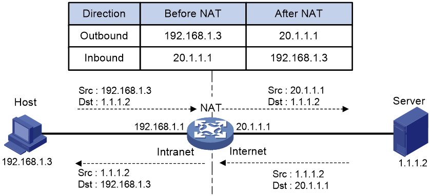
Figure 1 shows the basic NAT operating mechanism.
2. Upon receiving a response from the server, NAT translates the destination public address to the private address, and forwards the packet to the host.
The NAT operation is transparent to the terminals (the host and the server). NAT hides the private network from the external users and shows that the IP address of the internal host is 20.1.1.1.
NAT control
You can use ACLs to implement NAT control. The match criteria in the ACLs include the source IP address, source port number, destination IP address, destination port number, transport layer protocol, and VPN instance. Only packets permitted by an ACL are processed by NAT.
NAT translation methods
Static NAT
Static NAT creates a fixed mapping between a private address and a public address. It supports connections initiated from internal users to external network and from external users to the internal network. Static NAT applies to regular communications.
Source address translation
Source address translation is dynamic NAT translation that uses an address pool to translate addresses. It applies to the scenario where a large number of internal users access the external network.
The NO-PAT, port-based PAT, and port block-based PAT modes are supported.
NO-PAT
Not Port Address Translation (NO-PAT) translates a private IP address to an IP public address. The public IP address cannot be used by another internal host until it is released.
NO-PAT supports all IP packets.
Port-based PAT
Port Address Translation (PAT) translates multiple private IP addresses to a single public IP address by mapping the private IP address and source port to the public IP address and a unique port. PAT supports TCP and UDP packets, and ICMP request packets.
Figure 2 PAT operation
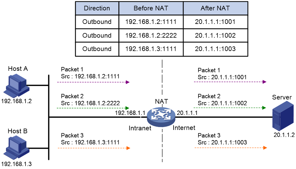
As shown in Figure 2, PAT translates the source IP addresses of the three packets to the same IP public address and translates their port numbers to different port numbers. Upon receiving a response, PAT translates the destination address and port number of the response, and forwards it to the target host.
PAT supports the following mappings:
· Endpoint-Independent Mapping (EIM)—Uses the same IP and port mapping (EIM entry) for packets from the same source IP and port to any destinations. EIM allows external hosts to initiate connections to the NAT IP addresses and ports of internal hosts. It allows internal hosts behind different NAT gateways to access each other.
· Address and Port-Dependent Mapping (APDM)—Uses different IP and port mappings for packets from the same source IP and port to different destination IP addresses and ports. APDM allows an external host to initiate connections to an internal host only under the condition that the internal host has previously accessed the external host. It is secure, but it does not allow internal hosts behind different NAT gateways to access each other.
Port block-based NAT
Port block-based NAT is a PAT translation based on port ranges. It maps multiple private IP addresses to one public IP address and uses a different port block for each private IP address. For example, the private IP address 10.1.1.1 of an internal host is mapped to the public IP address 202.1.1.1 and port block 10001 to 10256. When the internal host accesses public hosts, the source IP address 10.1.1.1 is translated to 202.1.1.1, and the source ports are translated to ports in the port block 10001 to 10256.
Port block-based NAT includes static and dynamic mappings. It applies to NAT444 and DS-Lite networks.
Static port block mapping
The NAT gateway computes a static port block mapping before address translation. The mapping is between a private IP address and a public IP address with a port block.
When an internal user initiates a connection to the external network, the system performs the following operations:
· Locates a static mapping based on the private IP address of the user and obtains the public IP address and the port block in the mapping.
· Selects a public port number in the port block.
· Translates the private IP address to the public IP address and assigns the selected public port number.
The NAT gateway uses private IP addresses, public IP addresses, a port range, and a port block size to compute static mappings:
1. Divides the port range by the port block size to get the number of available port blocks for each public IP address.
This value is the base number for mapping.
2. Sorts the port blocks in ascending order of the start port number in each block.
3. Sorts the private IP addresses and the public IP addresses separately in ascending order.
4. Maps the first base number of private IP addresses to the first public IP address and its port blocks in ascending order.
For example, the number of available port blocks of each public IP address is m. The first m private IP addresses are mapped to the first public IP address and the m port blocks in ascending order. The next m private IP addresses are mapped to the second IP address and the m port blocks in ascending order. The other static port block mappings are created by analogy.
Dynamic port block mapping
When an internal user initiates a connection to the external network, the dynamic port block-based NAT operates as follows:
1. Uses ACLs to implement translation control. It processes only packets that match an ACL permit rule.
2. Creates a mapping from the internal user's private IP address to a public IP address and a port block.
3. Translates the private IP address to the public IP address, and the source ports to ports in the selected port block for subsequent connections from the private IP address.
4. Withdraws the port block and deletes the dynamic port block mapping when all connections from the private IP address are disconnected.
Dynamic port block mapping supports port block extending. If the ports in the port block for a private address are all occupied, dynamic port block mapping translates the source port to a port in an extended port block.
Destination address translation
Destination address translation maps a public address and port number to the private IP address and port number of an internal server. This feature allows servers in the private network to provide services for external users.
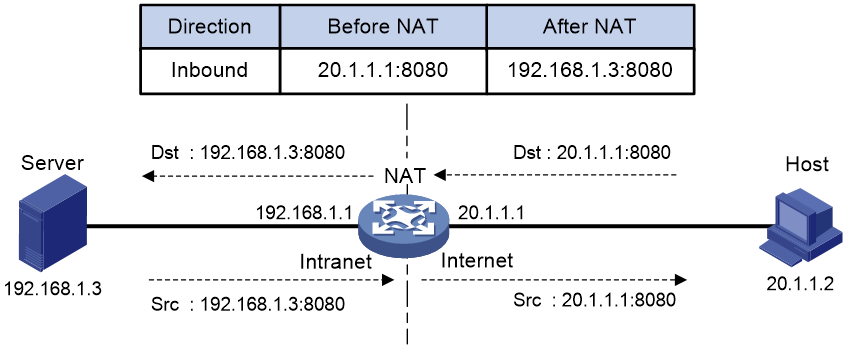
Figure 3 shows how destination address translation works:
1. Upon receiving a request from the host, NAT translates the public destination IP address and port number to the private IP address and port number of the internal server.
2. Upon receiving a response from the server, NAT translates the private source IP address and port number to the public IP address and port number.
Figure 3 Destination address translation operation
NAT entries
NAT session entry
NAT creates a NAT session entry for a session and creates an address mapping for the first packet in the session.
A NAT session entry contains extended NAT information, such as interface and translation method. Subsequent packets of the session are translated by using this entry.
· If the direction of the subsequent packets is the same as the direction of the first translated packet, NAT performs the source and destination address translation the same as the first packet.
· If the direction of the subsequent packets is opposite to the direction of the first translated packet, NAT perform reverse address translation. For example, if the source address of the first packet is translated, then the destination address of the subsequent packets is translated.
The session management module maintains the updating and aging of NAT session entries. For information about session management, see Security Configuration Guide.
EIM entry
If EIM is configured on the NAT device, the PAT mode will first create a NAT session entry, and then an EIM entry. The EIM entry is a 3-tuple entry, and it maps a private address/port to a public address/port. The EIM entry ensures:
· Subsequent new connections originating from the same source IP and port uses the same translation as the initial connection.
· Translates the address for new connections initiated from external hosts to the NAT address and port number based on the EIM entry.
An EIM entry ages out after all related NAT session entries age out.
NO-PAT entry
A NO-PAT entry maps a private address to a public address. The same mapping applies to subsequent connections originating from the same source IP.
A NO-PAT entry can also be created during the ALG process for NAT. For information about NAT ALG, see "NAT ALG."
A NO-PAT entry ages out after all related NAT session entries age out.
Port block-based entry
A port block-based entry maps a private IP address to a public IP address and a port block.
Port block-based entries include static and dynamic port block mappings. For information about these mappings, see "Static port block mapping" and "Dynamic port block mapping."
VRF-aware NAT
VRF-aware NAT allows users from different VRF (VPN instances) to access external networks and to access each other.
1. Upon receiving a request from a user in a VRF to an external network, NAT performs the following tasks:
¡ Translates the private source IP address and port number to a public IP address and port number.
¡ Records the VRF information, such as the VRF name.
2. When a response packet arrives, NAT performs the following tasks:
¡ Translates the destination public IP address and port number to the private IP address and port number.
¡ Forwards the packet to the target VRF.
The NAT Server feature supports VRF-aware NAT for external users to access the servers in a VPN instance. For example, to enable a host at 10.110.1.1 in VPN 1 to provide Web services for Internet users, configure NAT Server to use 202.110.10.20 as the public IP address of the Web server.
VRF-aware NAT is supported only in the global NAT policy in the current software version.
NAT hairpin
NAT hairpin allows internal hosts to access each other through NAT. The source and destination IP address of the packets are translated on the interface connected to the internal network.
NAT hairpin includes P2P and C/S modes:
· P2P—Allows internal hosts to access each other through NAT. The internal hosts first register their public addresses to an external server. Then, the hosts communicate with each other by using the registered IP addresses.
· C/S—Allows internal hosts to access internal servers through NAT addresses.
NAT ALG
NAT ALG (Application Level Gateway) translates address or port information in the application layer payloads to ensure connection establishment.
For example, an FTP application includes a data connection and a control connection. The IP address and port number for the data connection depend on the payload information of the control connection. This requires NAT ALG to translate the address and port information for data connection establishment.
NAT DNS mapping
The DNS server is typically on the public network. For the users on the public network to access an internal server, you can configure the NAT Server feature on the NAT device. The NAT Server maps the public IP address and port number to the private IP address and port number of the internal server. Then the public users can access the internal server through the server's domain name or public IP address.
When a user is in the private network, the user cannot access the internal server by using the domain name of the server. This is because the DNS response contains the public IP address of the server. In this case, you can configure NAT DNS mapping to solve the problem.
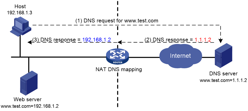
As shown in Figure 4, NAT DNS mapping works as follows:
1. The host sends a DNS request containing the domain name of the internal Web server.
2. Upon receiving the DNS response, the NAT device performs a DNS mapping lookup by using the domain name in the response. A NAT DNS mapping maps the domain name to the public IP address, public port number, and the protocol type for the internal server.
3. If a match is found, the NAT continues to compare the public address, public port number, and the protocol type with the NAT Server configuration. The NAT Server configuration maps the public IP address and port number to the private IP address and port number for the internal server.
4. If a match is found, NAT translates the public IP address in the response into the private IP address of the Web server.
5. The internal host receives the DNS response, and obtains the private IP address of the Web server.
NAT DNS mapping is supported in the interface-based NAT policy in the current software version.
NAT444
About NAT444
NAT444 provides carrier-grade NAT by unifying the NAT444 gateway, AAA server, and log server. NAT444 introduces a second layer of NAT on the carrier side, with few changes on the customer side and the application server side. With port block assignment, NAT444 supports user tracking. It has become a preferred solution for carriers in transition to IPv6.
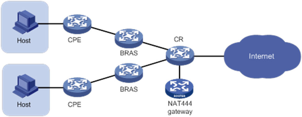
Centralized NAT444 deployment
Centralized NAT444 deployment is implemented by installing a NAT processing slot on the CR device or by connecting a NAT444 device to the CR.
As shown in Figure 5, when an internal user accesses the external network, NAT444 is implemented as follows:
1. The CPE device performs the first NAT.
2. After the user passes AAA authentication on the BRAS device, this user is assigned a private IP address.
3. When the packet destined to the external network, the NAT444 gateway performs the second NAT.
Figure 5 Centralized NAT444 deployment
Device access with overlapping addresses
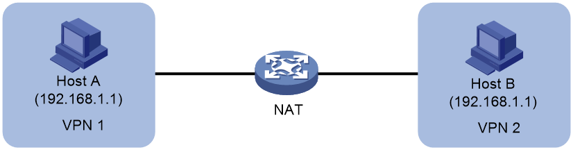
Configuring twice NAT
As shown in Figure 6, two hosts are in different VPN instances with overlapping addresses. For the hosts to access each other, both the source and destination addresses of packets between the two VPNs need to be translated. Configure static NAT on both interfaces connected to the VPNs on the NAT device.
1. Configure a static outbound NAT mapping between 192.168.1.1 in VPN 1 and 172.16.1.1 in VPN 2.
2. Configure a static outbound NAT mapping between 192.168.1.1 in VPN 2 and 172.16.2.1 in VPN 1.
3. When the twice NAT takes effect, the hosts can access each other.
Figure 6 VPN access with overlapping address
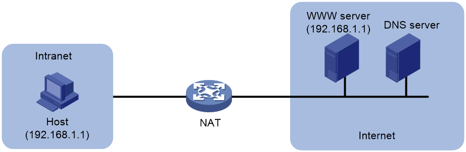
Configuring outbound bidirectional NAT for internal-to-external access through domain name
As shown in Figure 7, the IP address of the Web server overlaps with the private host at 192.168.1.0/24. Configure dynamic NAT ALG and outbound dynamic NAT to allow the internal host to access the external Web server by using the server's domain name.
1. The host sends a DNS request to the DNS server in the external network.
2. After receiving a DNS reply, the NAT device with NAT ALG configured translates the Web server's IP address in the DNS reply payload to a dynamically assigned public address 10.1.1.1.
3. Configure inbound dynamic NAT ALG to make sure the internal host reaches the Web server instead of another internal host. NAT ALG can translate the Web server's IP address in the DNS reply payload to a dynamically assigned public address 10.1.1.1.
4. After receiving the DNS reply from the NAT device, the host sends a packet with the source IP address 192.168.1.1 and destination IP address 10.1.1.1.
5. The NAT device with outbound dynamic NAT configured translates the source IP address of the packet to a dynamically assigned public address 20.1.1.1. NAT ALG translates the destination IP address of the packet to the IP address of the Web server.
Figure 7 Internal-to-external access through domain name
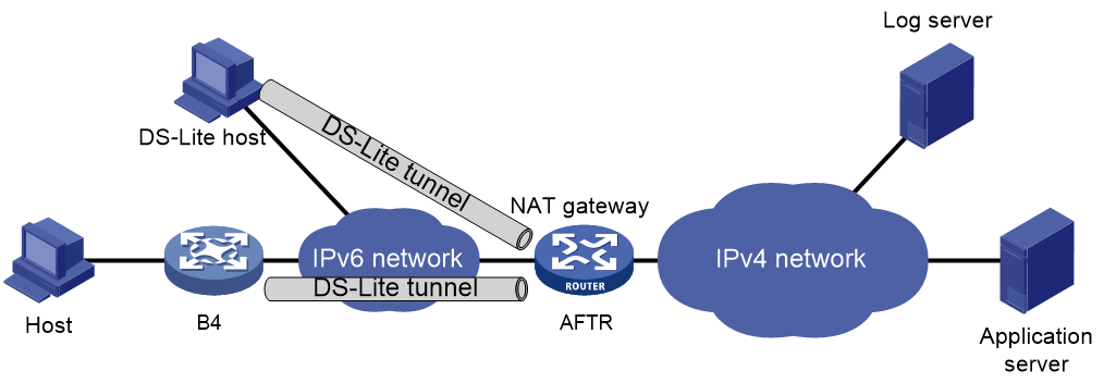
NAT in the DS-Lite network
DS-Lite combines tunneling and NAT to allow an IPv4 private network to access the IPv4 public network over an IPv6 network. For more information about DS-Lite, see tunneling configuation in VPN Configuration Guide.
DS-Lite B4 address translation is configured on the AFTR and performs port block-based translation based on the IPv6 address of the B4 element. The B4 element refers to a B4 router or a DS-Lite host. DS-Lite B4 address translation dynamically maps a public IPv4 address and a port block to the IPv6 address of the B4 element. The DS-Lite host or hosts behind the B4 router use the mapped public IPv4 address and port block to access the public IPv4 network.
DS-Lite B4 address translation supports user tracing for DS-Lite hosts based on the port block.
Only dynamic port block mapping is supported for B4 address translation.
Figure 8 DS-Lite B4 address translation
Configuring global NAT
About the global NAT policy
The global NAT policy is applicable to the scenario where the external interface is not fixed. Compared with interface-based NAT policies, you do not need to change relevant configurations if the external interface changes, which reduces maintenance costs.
The global NAT policy contains NAT rules. A NAT rule contains the following elements:
· Packet match criteria—The packet match criteria can match packets by source IP address, destination IP address, service type, source security zone, or destination security zone. You can configure different packet match criteria for different NAT rules. The device translates the IP addresses of the matching packets. A matching packet refers to a packet that matches all match criteria in a NAT rule.
· Action—Action to take on matching packets, which can be source address translation (SNAT) or destination address translation (DNAT). SNAT can hide the IP addresses of internal hosts to external devices. DNAT is commonly used for internal servers to access external users. A combination of SNAT and DNAT translates the source and destination IP addresses of packets.
NAT rules include the following types:
· SNAT rule—Used for source address translation.
· DNAT rule—Used for destination address translation.
· SNAT+ DNAT rule—Used for source address translation and destination address translation both.
Global NAT tasks at a glance
1. Configuring the global NAT policy
a. Creating the global NAT policy
c. Rearranging NAT rules in the policy to adjust their priority
2. (Optional.) Configuring NAT ALG
3. (Optional.) Configuring high availability for NAT
¡ Configuring the HA group for NAT
4. (Optional.) Configuring NAT in specific networks
¡ Enabling NAT reply redirection
¡ Enabling the deletion of timestamps in TCP SYN and SYN ACK packets
5. (Optional.) Configuring NAT maintenance
¡ Configuring periodic NAT statistics collection
¡ Enabling statistics collection for NAT session creation rate
¡ Specifying a probe method for detecting reachability of NAT address group members
¡ Enabling sending ICMP error messages for NAT failures
6. (Optional.) Configuring NAT logging
¡ Configuring NAT session logging
¡ Configuring NAT444 user logging
¡ Configuring NAT alarm logging
¡ Enabling logging for IP usage of a NAT address group in NO-PAT mode
Configuring the global NAT policy
About the global NAT policy
The global NAT policy contains a set of NAT rules to identify and translate matching packets. Compared with interface-based NAT policies, you do not need to apply the global NAT policy to any interface.
The global NAT policy contains NAT rules. A NAT rule contains the following elements:
· Packet match criteria—The packet match criteria can match packets by source IP address, destination IP address, service type, source security zone, or destination security zone. You can configure different packet match criteria for different NAT rules. The device translates the IP addresses of the matching packets. A matching packet refers to a packet that matches all match criteria in a NAT rule.
· Action—Action to take on matching packets, which can be source address translation or destination address translation.
Restrictions and guidelines for global NAT policy configuration
If no object group or security zone is specified for a NAT rule, this rule matches all packets.
NAT rules in the global NAT policy take effect only when the Config status of the policy is Active. You can use the display nat global-policy command to verify the status of the global policy.
· When the status is Active, the NAT rules in the global NAT policy are sorted in descending order of their configuration order. A rule configured earlier has a higher priority. The matching process stops when a packet matches a NAT rule. You can use the display this command to view the configuration order of the NAT rules.
· If the status is Inactive, the NAT rules are not used to match packets.
Up to 10000 NAT rules can be created for the global NAT policy.
When you configure a security policy, the device performs address translation in the following descending order:
1. Destination address translation.
2. Security policy rule matching.
3. Source address translation.
Make sure the destination address in the matched packet has been NATed and the source address in the matched packet is not NATed.
Creating the global NAT policy
1. Enter system view
system-view
2. Create the global NAT policy and enter its view.
nat global-policy
Configuring NAT rules
Restrictions and guidelines
When you configure a DNAT or SNAT+DNAT rule, follow these restrictions and guidelines:
· The packet match criteria cannot match packets by destination security zone.
· Only one destination address after NAT is supported:
¡ You cannot configure the action dnat ip-address local-address [ local-port local-port ] command multiple times to configure multiple destination addresses after NAT.
¡ Specify an object group that has only one IP address when you configure the action dnat object-group ipv4-object-group-name [ local-port local-port ] command.
For an object group-based static mapping to take effect, the object group cannot have excluded addresses.
Procedure
1. Enter system view.
system-view
2. Enter the global NAT policy view.
nat global-policy
3. Create a NAT rule and enter its view.
rule name rule-name
By default, no NAT rule exists.
4. (Optional.) Configure a description for the NAT rule.
description text
By default, no description is configured for the NAT rule.
5. Specify packet match criteria for the rule.
¡ Specify a source IP address match criterion.
source-ip { object-group-name | host ip-address | subnet subnet-ip-address mask-length }
By default, no source IP address match criterion is specified for the NAT rule.
The address object group must already exist, or source IP addresses in all packets can match the criteria.
¡ Specify a destination IP address match criterion.
destination-ip { object-group-name | host ip-address | subnet subnet-ip-address mask-length }
By default, no destination IP address match criterion is specified for the NAT rule.
The address object group must already exist, or destination IP addresses in all packets can match the criteria.
¡ Specify a service object group.
service object-group-name
By default, no service type is specified for the NAT rule.
¡ Specify a source security zone.
source-zone source-zone-name
By default, no source security zone is specified for the NAT rule.
¡ Specify a destination security zone.
destination-zone destination-zone-name
By default, no destination security zone is specified for the NAT rule.
6. Specify an address translation method for the NAT rule.
¡ Specify a source address translation method.
NO-PAT:
action snat address-group { group-id | name group-name } no-pat [ reversible ]
PAT:
action snat address-group { group-id | name group-name } [ port-preserved ]
Easy IP:
action snat easy-ip [ port-preserved ]
Static NAT:
action snat static { ip-address global-address | object-group object-group-name | subnet subnet-ip-address mask-length }
NO-NAT:
action snat no-nat
By default, no source address translation method is specified for the NAT rule.
¡ Specify a destination address translation method.
Static translation:
action dnat ip-address local-address [ port local-port ]
NO-NAT:
action dnat no-nat
By default, no destination address translation method is specified for the NAT rule.
7. (Optional.) Enable hit counting for the NAT rule.
counting enable
By default, hit counting is disabled for the NAT rule.
Rearranging NAT rules in the policy to adjust their priority
About this task
In the global NAT policy, the priority of NAT rules are determined by the configuration order. A rule configured earlier has a higher priority. You can use the rule move command to rearrange the NAT rules to adjust their priority.
Restrictions and guidelines
In the global NAT policy, the priority of NAT rules of the same type are determined by the priority value. The smaller the value, the higher the priority. You can move the location of the NAT rules to adjust their priority as the following rules:
· Move the rule nat-rule-name1 to the line after the rule nat-rule-name2 (called the reference rule). The priority value of the reference rule is not changed. The priority value of the moved rule equals the priority value of the reference rule plus one.
· Move the rule nat-rule-name1 to the line before the rule nat-rule-name2. The priority value of the reference rule is not changed. The priority value of the moved rule equals the priority value of the reference rule minus one.
Procedure
1. Enter system view.
system-view
2. Enter the global NAT policy view.
nat global-policy
3. Rearrange NAT rules to change their priority.
rule move rule-name1 { after | before } [ rule-name2 ]
Disabling NAT rules
Restrictions and guidelines
This feature does not delete a NAT rule, but makes the rule ineffective. To delete a NAT rule, use the undo rule name command.
Procedure
1. Enter system view.
system-view
2. Enter the global NAT policy view.
nat global-policy
3. Enter the view of a NAT rule.
rule name rule-name
4. Disable the NAT rule.
disable
By default, NAT rules are enabled.
Configuring NAT ALG
1. Enter system view.
system-view
2. Configure NAT ALG for a protocol or all protocols.
nat alg { all | dns | ftp | h323 | icmp-error | ils | mgcp | nbt | pptp | rsh | rtsp | sccp | sctp | sip | sqlnet | tftp | xdmcp }
By default, NAT ALG is enabled for the DNS, FTP, PPTP, RSTP protocols and ICMP error messages only.
Enabling NAT port halving
About this task
After you enable NAT port halving in VRRP load balancing on an IRF fabric, each port block will be equally divided between the two devices. The two devices will use different ports to translate packets from the same IP address, avoiding port assignment conflicts.
For more information about the IRF fabric, see Virtual Technologies Configuration Guide.
Restrictions and guidelines
Do not use this feature in VRRP standard mode on an IRF fabric or when the device works in standalone mode.
Procedure
1. Enter system view.
system-view
2. Enable NAT port halving.
nat port-load-balance enable slot slot-number
By default, NAT port halving is disabled.
Configuring the HA group for NAT
About the HA group for NAT
If only one NAT device is deployed in the internal network, internal users cannot access the external network when the NAT device fails. To avoid this situation, configure the HA group for NAT. In the HA group plan, the two devices in an HA group are capable of processing NAT services. Session entries, session relation entries, NAT port block entries, and NAT configurations are synchronized through the HA channel. When one device fails, the other device takes over.
For more information about configuring the HA group, see High Availability Configuration Guide.
Operating mechanism
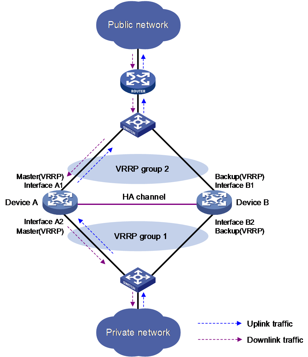
Typically, the master device in the VRRP group processes NAT services in the HA network. The following example illustrates how the HA group in active/standby mode ensures uninterrupted NAT services when the master device fails.
As shown in Figure 17, Device A acts as the primary device and Device B acts as the secondary device in an HA group. Device A synchronizes its session entries, session relation entries, and port block entries to Device B in real time through the HA channel. Downlinks of Device A and Device B are in VRRP group 1 and uplinks of Device A and Device B are in VRRP group 2. VRRP groups are associated with the HA group. RBM selects Device A as the master device for address translation based on the link status or forwarding capability of Device A.
When the two devices receive ARP requests for MAC addresses corresponding to public IP addresses in the NAT address group or port block group, Device A uses the virtual MAC address of the VRRP group to answer the requests. This mechanism ensures that Device A performs address translation for forward and reverse traffic.
Figure 9 HA group in active/standby mode
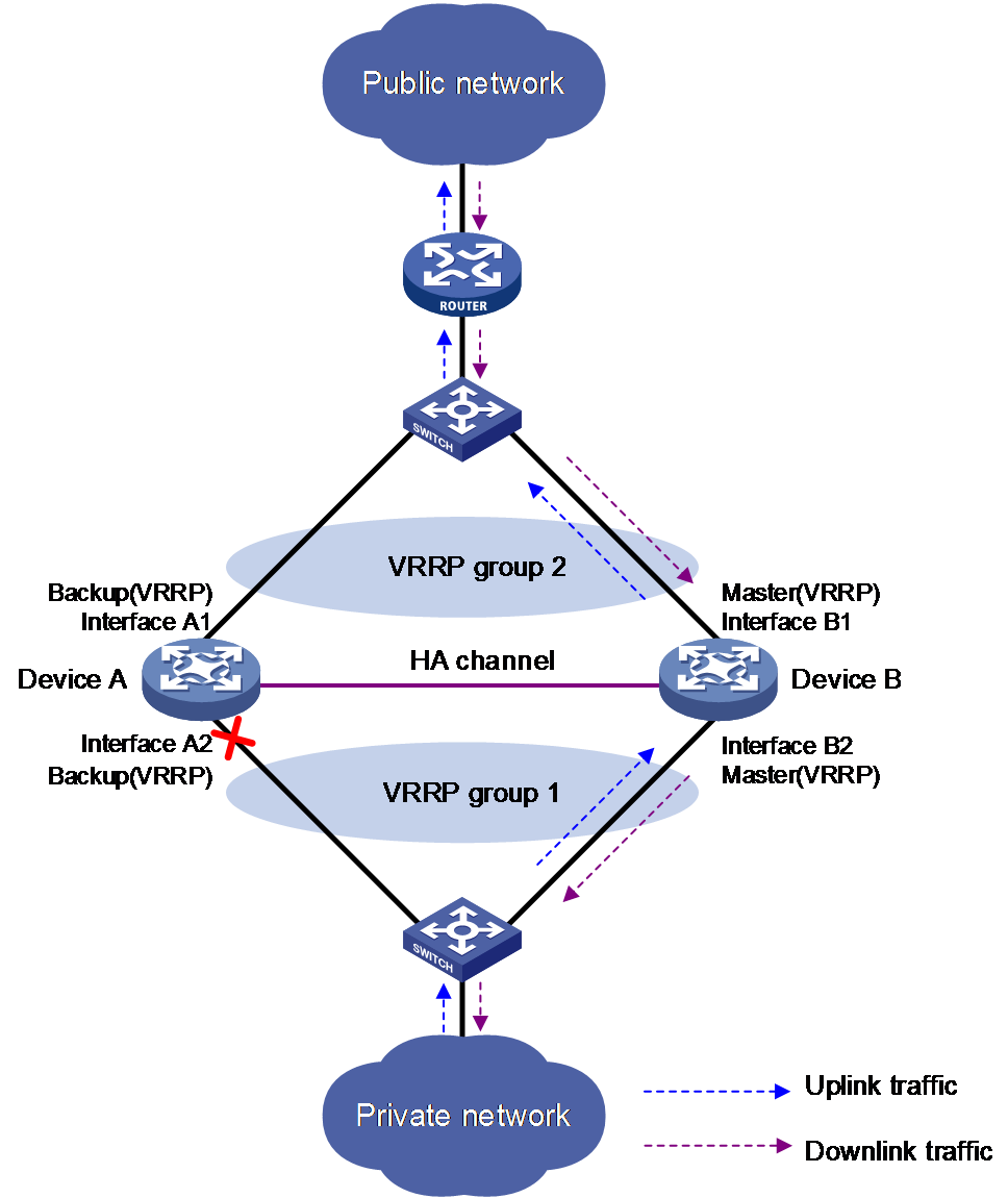
As shown in Figure 18, when Interface A2 of Device A fails, Device B becomes the master device in the VRRP group. Because Device B has NAT configuration information and service entries, NAT services are not interrupted after link switchover.
Figure 10 Traffic switchover in active/standby mode
Configuring the active/standby mode
Restrictions and guidelines
Execute the vrrp command in NAT rule view on the primary device in the HA group.
Procedure
1. Enter system view.
system-view
2. Enter global NAT policy view.
nat global-policy
3. Enter NAT rule view.
rule name rule-name
4. Bind the NAT rule to a VRRP group.
vrrp virtual-router-id
By default, a NAT rule is not bound to any VRRP group.
Configuring the dual-active mode
Restrictions and guidelines
Select one of the following methods for VRRP group binding according to the NAT resource allocation between the two devices in the HA group:
· If the two devices share addresses in the same NAT address group, execute the vrrp command on the primary device. To prevent different master devices from using the same IP-port mapping for different hosts, specify the PAT translation mode for NAT rules and execute the nat remote-backup port-alloc command on the primary device.
· If the two devices use addresses in different NAT address groups, user traffic with different source IP addresses is identified by source IP address match criteria in NAT rules. To enable different master devices to translate the forward user traffic, specify different gateway addresses for different internal users. To direct the reverse traffic to different master devices, bind NAT rules to different VRRP groups on the primary device for load sharing.
Procedure
1. Enter system view.
system-view
2. Enter global NAT policy view.
nat global-policy
3. Enter NAT rule view.
rule name rule-name
4. Bind the NAT rule to a VRRP group.
vrrp virtual-router-id
By default, a NAT rule is not bound to any VRRP group.
5. (Optional.) Specify NAT port block ranges for the two devices in the HA group.
a. Return to global NAT policy view.
quit
b. Return to system view.
quit
c. Specify NAT port ranges for the two devices in the HA group.
nat remote-backup port-alloc { primary | secondary }
By default, the two devices in the HA group share NAT port resources.
The following table describes port ranges indicated by the keywords:
|
Keyword |
Port ranges |
|
primary |
If you do not configure a port range for public addresses, the available port range includes 1 to 255, 512 to 769, 1024 to 3513, and 6000 to 35769. If a port range is configured by executing the port-range command, the first half of the configured port range is available. |
|
secondary |
If you do not configure a port range for public addresses, the available port range includes 256 to 511, 770 to 1023, 3514 to 5999, and 35770 to 65535. If a port range is configured by executing the port-range command, the second half of the configured port range is available. |
Configuring NAT in specific networks
Enabling NAT reply redirection
About this task
In some network scenarios, the inbound dynamic NAT is configured with tunneling, and multiple tunnel interfaces use the same NAT address group. In this case, the device will translate the source IP addresses of packets from different tunnels into the same NAT address before forwarding them. When the forwarding interface receives the reply packets, the device, by default, will not look up the NAT session table. This will cause the incorrect forwarding of the reply packets. To solve the problem, you can enable the NAT reply redirection feature on the forwarding interface. NAT reply redirection allows the interface to use the NAT session table to translate the destination IP addresses for NAT reply packets and find the correct output interfaces for those NATed reply packets.
Procedure
1. Enter system view.
system-view
2. Enter interface view.
interface interface-type interface-number
3. Enable NAT reply redirection.
nat redirect reply-route enable
By default, NAT reply redirection is disabled.
Enabling the deletion of timestamps in TCP SYN and SYN ACK packets
About this task
With this feature configured, the system deletes the timestamps from the TCP SYN and SYN ACK packets after dynamic address translation.
If PAT mode is configured on an interface by using nat inbound or nat outbound, and the tcp_timestams and tcp_tw_recycle function is configured on the TCP server, TCP connections might not be established. To solve the problem, you can shut down the tcp_tw_recycle function or configure the nat timestamp delete command.
Procedure
1. Enter system view.
system-view
2. Enable the deletion of timestamps in TCP SYN and SYN ACK packets
nat timestamp delete [ vpn-instance vpn-instance-name ]
By default, the deletion of timestamps in TCP SYN and SYN ACK packets is disabled.
You can enable this feature for multiple VPN instances by repeating the command with different VPN parameters.
Configuring NAT maintenance
Configuring periodic NAT statistics collection
About this task
This feature periodically counts sessions and port block assignment failures for address groups.
Restrictions and guidelines
This feature might cause intensive CPU usage. You can disable the feature when CPU resources are insufficient.
Procedure
1. Enter system view.
system-view
2. Enable periodic NAT statistics collection.
nat periodic-statistics enable
By default, periodic NAT statistics collection is disabled.
3. Configure the interval for periodic NAT statistics collection.
nat periodic-statistics interval interval
By default, the interval for periodic NAT statistics collection is 300 seconds.
A narrower interval indicates intensive CPU usage. As a best practice, use the default interval value.
Enabling statistics collection for NAT session creation rate
About this task
This feature collects information about NAT session creation rates. To view the statistics, use the display nat statistics command.
Procedure
1. Enter system view.
system-view
2. Enable statistics collection for NAT session creation rate.
nat session create-rate enable
By default, statistics collection for NAT session creation rate is disabled.
Specifying a probe method for detecting reachability of NAT address group members
About this task
The NAT address group probing uses an NQA template to detect the reachability of the addresses in the group. For information about NQA, see Network Management and Monitoring Configuration Guide.
The device periodically sends probe packets to the specified destination address in the NQA template. The source IP addresses in the probe packets are the IP addresses in the NAT address group.
· If the device receives a response packet for a probe, the probed source IP address can be used for address translation.
· If the device does not receive a response packet for a probe, the probed source IP address will be excluded from address translation temporarily. However, in the next NQA operation period, this excluded IP address is also probed. If a response is received in this round, the IP address can be used for address translation.
Restrictions and guidelines
You can specify multiple NQA templates in one NAT address group view. An IP address in the address group is identified as reachable as long as one probe for this IP address succeeds.
This feature is applicable to NAT address groups used for outbound address translation. The manually configured excluded IP addresses are not probed.
Make sure the NQA template used for NAT address group probing does not have source IP address configured.
Procedure
1. Enter system view.
system-view
2. Enter NAT address group view.
nat address-group group-id [ name group-name ]
3. Specify a probe method for the NAT address group.
probe template-name
By default, no probe method is specified for a NAT address group.
You can specify a nonexistent probe method. The probing takes effect only after you create and configure the NQA template.
Enabling sending ICMP error messages for NAT failures
About this task
By default, the device does not send ICMP error messages when NAT fails. Disabling sending ICMP error messages for NAT failures reduces useless packets, saves bandwidth, and avoids exposing the firewall IP address to the public network.
Procedure
1. Enter system view.
system-view
2. Enable sending ICMP error messages for NAT failures.
nat icmp-error reply
By default, no ICMP error messages are sent for ICMP packet translation failures.
Configuring NAT logging
Configuring NAT session logging
About this task
NAT session logging records NAT session information, including translation information and access information.
A NAT device generates NAT session logs for the following events:
· NAT session establishment.
· NAT session removal. This event occurs when you add a configuration with a higher priority, remove a configuration, change ACLs, when a NAT session ages out, or when you manually delete a NAT session.
· Active NAT session logging. Active NAT flows refer to NAT sessions that exist within a period of time. When the specified interval for logging active NAT flows expires, the device records the existing NAT session information and generates a log. Logging for active NAT flows only supports flow log output to log hosts. For more information, see flow log configuration in Network Management and Monitoring Configuration Guide.
Procedure
1. Enter system view.
system-view
2. Enable NAT logging.
nat log enable [ acl { ipv4-acl-number | name ipv4-acl-name } ]
By default, NAT logging is disabled.
3. Enable NAT session logging.
¡ For NAT session establishment events:
nat log flow-begin
¡ For NAT session removal events:
nat log flow-end
¡ For active NAT flows:
nat log flow-active time-value
By default, NAT session logging is disabled.
Configuring NAT444 user logging
About this task
NAT444 user logs are used for user tracing. The NAT444 gateway generates a user log whenever it assigns or withdraws a port block. The log includes the private IP address, public IP address, and port block. You can use the public IP address and port numbers to locate the user's private IP address from the user logs.
A NAT444 gateway generates NAT user logs when one of the following events occurs:
· A port block is assigned.
For the NAT444 static port block mapping, the NAT444 gateway generates a user log when it translates the first connection from a private IP address.
For the NAT444 dynamic port block mapping, the NAT444 gateway generates a user log when it assigns or extends a port block for a private IP address.
· A port block is withdrawn.
For the NAT444 static port block mapping, the NAT444 gateway generates a user log when all connections from a private IP address are disconnected.
For the NAT444 dynamic port block mapping, the NAT444 gateway generates a user log when all the following conditions are met:
¡ All connections from a private IP address are disconnected.
¡ The port blocks (including the extended ones) assigned to the private IP address are withdrawn.
¡ The corresponding mapping entry is deleted.
Prerequisites
Before configuring NAT444 user logging, you must configure the custom NAT444 log generation and outputting features. For more information, see the information center in Network Management and Monitoring Configuration Guide.
Procedure
1. Enter system view.
system-view
2. Enable NAT logging.
nat log enable [ acl { ipv4-acl-number | name ipv4-acl-name } ]
By default, NAT logging is disabled.
The acl keyword does not take effect on NAT444 user logging.
3. Enable NAT444 user logging. Choose the options to configure as needed:
¡ For port block assignment:
nat log port-block-assign
¡ For port block withdrawal:
nat log port-block-withdraw
By default, NAT444 user logging is disabled.
Configuring NAT alarm logging
About this task
Packets that need to be translated are dropped if the NAT resources are not enough. In NO-PAT, the NAT resources refer to the public IP addresses. In EIM PAT, the NAT resources refer to public IP addresses and ports. In NAT444, the NAT resources refer to public IP addresses, port blocks, or ports in port blocks. NAT alarm logging monitors the usage of NAT resources and outputs logs if the NAT resources are not enough.
For NAT444 dynamic port block mappings, an alarm log is generated upon the port block assignment failure or the failure that port resources cannot meet the user address translation requirement.
Restrictions and guidelines
The nat log alarm command take effect only after you use the nat log enable command to enable NAT logging.
Prerequisites
Before configuring NAT alarm logging, you must configure the custom NAT log generation and outputting features. For more information, see the information center in Network Management and Monitoring Configuration Guide.
Procedure
1. Enter system view.
system-view
2. Enable NAT logging.
nat log enable [ acl { ipv4-acl-number | name ipv4-acl-name } ]
By default, NAT logging is disabled.
The acl keyword does not take effect on NAT alarm logging.
3. Enable NAT alarm logging.
nat log alarm
By default, NAT alarm logging is disabled.
An NAT alarm log is output when NAT resources run out.
4. (Optional.) Set the NAT444 port block usage threshold.
nat log port-block usage threshold threshold-value
By default, the NAT444 port block usage threshold is 90%.
The system generates alarm logs if the port block usage exceeds the threshold.
Enabling logging for IP usage of a NAT address group in NO-PAT mode
About this task
The system generates a log if the IP usage of a NAT address group exceeds the threshold.
Restrictions and guidelines
This feature takes effect only after you enable NAT logging by using the nat log enable command.
Procedure
1. Enter system view.
system-view
2. Enable NAT logging.
nat log enable [ acl { ipv4-acl-number | name ipv4-acl-name } ]
By default, NAT logging is disabled.
The acl keyword does not take effect on the logging for IP usage of a NAT address group in NO-PAT mode.
3. Enable logging for the IP usage of a NAT address group in NO-PAT mode and set a threshold.
nat log no-pat ip-usage [ threshold value ]
By default, logging is disabled for the IP usage of a NAT address group.
Display and maintenance commands for global NAT
Execute display commands in any view and reset commands in user view.
|
Task |
Command |
|
Display the NAT ALG status for all supported protocols |
display nat alg |
|
Display all NAT configuration information. |
display nat all |
|
Display NAT address group information. |
display nat address-group [ group-id ] |
|
Display NAT logging configuration. |
display nat log |
|
Display information about NAT NO-PAT entries. |
In standalone mode: display nat no-pat [ slot slot-number [ cpu cpu-number ] ] In IRF mode: display nat no-pat [ chassis chassis-number slot slot-number [ cpu cpu-number ] ] |
|
Display IP usage of NAT address groups in NO-PAT mode. |
In standalone mode: display nat no-pat ip-usage [ address-group { group-id | name group-name } ] [ slot slot-number [ cpu cpu-number ] ] In IRF mode: display nat no-pat ip-usage [ address-group { group-id | name group-name } ] [ chassis chassis-number slot slot-number [ cpu cpu-number ] ] |
|
Display periodic NAT statistics. |
In standalone mode: display nat periodic-statistics { address-group [ group-id | name group-name ] | ip global-ip } [ slot slot-number [ cpu cpu-number ] ] In IRF mode: display nat periodic-statistics { address-group [ group-id | name group-name ] | ip global-ip } [ chassis chassis-number slot slot-number [ cpu cpu-number ] ] |
|
Display NAT sessions. |
In standalone mode: display nat session [ [ responder ] { source-ip source-ip | destination-ip destination-ip } * [ vpn-instance vpn-instance-name ] ] [ slot slot-number [ cpu cpu-number ] ] [ verbose ] In IRF mode: display nat session [ [ responder ] { source-ip source-ip | destination-ip destination-ip } * [ vpn-instance vpn-instance-name ] ] [ chassis chassis-number slot slot-number [ cpu cpu-number ] ] [ verbose ] |
|
Display NAT statistics. |
In standalone mode: display nat statistics [ summary ] [ slot slot-number [ cpu cpu-number ] ] In IRF mode: display nat statistics [ summary ] [ chassis chassis-number slot slot-number [ cpu cpu-number ] ] |
|
Display NAT port block mappings. |
In standalone mode: display nat port-block { dynamic [ address-group { group-id | name group-name } ] [ ds-lite-b4 ] | static [ port-block-group group-id ] } [ slot slot-number [ cpu cpu-number ] ] In IRF mode: display nat port-block { dynamic [ address-group { group-id | name group-name } ] [ ds-lite-b4 ] | static [ port-block-group group-id ] } [ chassis chassis-number slot slot-number [ cpu cpu-number ] ] |
|
Display the port block usage for address groups. |
In standalone mode: display nat port-block-usage [ address-group group-id ] [ slot slot-number [ cpu cpu-number ] ] In IRF mode: display nat port-block-usage [ address-group group-id ] [ chassis chassis-number slot slot-number [ cpu cpu-number ] ] |
|
Display NAT address group probe information. |
display nat probe address-group [ group-id ] |
|
Clear NAT counting statistics. |
reset nat count statistics { all | dynamic | global-policy | server | static | static-port-block } |
|
Clear periodic NAT statistics. |
In standalone mode: reset nat periodic-statistics [ slot slot-number [ cpu cpu-number ] ] In IRF mode: reset nat periodic-statistics [ chassis chassis-number slot slot-number [ cpu cpu-number ] ] |
|
Clear NAT sessions. |
In standalone mode: reset nat session [ slot slot-number [ cpu cpu-number ] ] In IRF mode: reset nat session [ chassis chassis-number slot slot-number [ cpu cpu-number ] ] |
Global NAT configuration examples
Example: Configuring outbound one-to-one static NAT
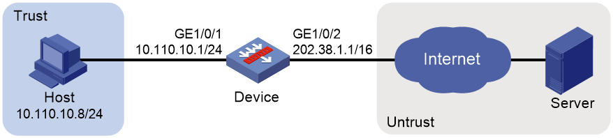
Network configuration
Configure static NAT to allow the host at 10.110.10.8/24 to access the server at 201.20.1.1/24 on the Internet.
Figure 11 Network diagram
Procedure
1. Assign IP addresses to interfaces:
# Assign an IP address to interface GigabitEthernet 1/0/1.
<Device> system-view
[Device] interface gigabitethernet 1/0/1
[Device-GigabitEthernet1/0/1] ip address 10.110.10.1 24
[Device-GigabitEthernet1/0/1] quit
# Assign IP addresses to other interfaces in the same way. (Details not shown.)
2. Add interfaces to security zones.
[Device] security-zone name trust
[Device-security-zone-Trust] import interface gigabitethernet 1/0/1
[Device-security-zone-Trust] quit
[Device] security-zone name untrust
[Device-security-zone-Untrust] import interface gigabitethernet 1/0/2
[Device-security-zone-Untrust] quit
3. Configure settings for routing.
This example configures a static route, and the next hop in the routes is 202.38.1.2.
[Device] ip route-static 201.20.1.0 24 202.38.1.2
4. Configure a security policy:
# Configure a rule named trust-untrust to permit the packets from the host to the server.
[Device] security-policy ip
[Device-security-policy-ip] rule name trust-untrust
[Device-security-policy-ip-1-trust-untrust] source-zone trust
[Device-security-policy-ip-1-trust-untrust] destination-zone untrust
[Device-security-policy-ip-1-trust-untrust] source-ip-host 10.110.10.8
[Device-security-policy-ip-1-trust-untrust] destination-ip-host 201.20.1.1
[Device-security-policy-ip-1-trust-untrust] action pass
[Device-security-policy-ip-1-trust-untrust] quit
[Device-security-policy-ip] quit
5. Configure NAT:
# Configure a one-to-one static NAT mapping between the private address 10.110.10.8 and the public address 202.38.1.100.
[Device] nat global-policy
[Device-nat-global-policy] rule name rule1
[Device-nat-global-policy-rule-rule1] source-ip host 10.110.10.8
[Device-nat-global-policy-rule-rule1] source-zone trust
[Device-nat-global-policy-rule-rule1] destination-zone untrust
[Device-nat-global-policy-rule-rule1] action snat static ip-address 202.38.1.100
Verifying the configuration
# Verify that the host at 10.110.10.8/24 can access the server on the Internet. (Details not shown.)
# Display static NAT configuration.
[Device] display nat global-policy
NAT global-policy information:
Totally 1 NAT global-policy rules.
Rule name: rule1
Type : nat
SrcIP address : 10.110.10.8
Source-zone name : Trust
Destination-zone name : Untrust
SNAT action:
Ipv4 address: 202.38.1.100
NAT counting : 0
Config status: Active
# Display NAT sessions.
[Device] display nat session verbose
Slot 1:
Initiator:
Source IP/port: 10.110.10.8/54765
Destination IP/port: 201.20.1.1/23
DS-Lite tunnel peer: -
VPN instance/VLAN ID/Inline ID: -/-/-
Protocol: TCP(6)
Inbound interface: GigabitEthernet1/0/1
Source security zone: Trust
Responder:
Source IP/port: 201.20.1.1/23
Destination IP/port: 202.38.1.100/54765
DS-Lite tunnel peer: -
VPN instance/VLAN ID/Inline ID: -/-/-
Protocol: TCP(6)
Inbound interface: GigabitEthernet1/0/2
Source security zone: Untrust
State: TCP_ESTABLISHED
Application: TELNET
Rule ID: -/-/-
Rule name:
Start time: 2017-05-19 10:57:47 TTL: 1195s
Initiator->Responder: 8 packets 375 bytes
Responder->Initiator: 10 packets 851 bytes
Total sessions found: 1
Example: Configuring outbound dynamic NAT (non-overlapping addresses)
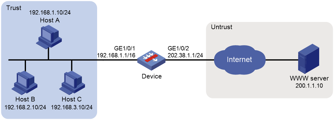
Network configuration
As shown in Figure 12, a company has a private address 192.168.0.0/16 and two public IP addresses 202.38.1.2 and 202.38.1.3. Configure outbound dynamic NAT to allow only internal users on subnet 192.168.1.0/24 to access the Internet.
Procedure
1. Assign IP addresses to interfaces:
# Assign an IP address to interface GigabitEthernet 1/0/1.
<Device> system-view
[Device] interface gigabitethernet 1/0/1
[Device-GigabitEthernet1/0/1] ip address 192.168.1.1 16
[Device-GigabitEthernet1/0/1] quit
# Assign IP addresses to other interfaces in the same way. (Details not shown.)
2. Add interfaces to security zones.
[Device] security-zone name trust
[Device-security-zone-Trust] import interface gigabitethernet 1/0/1
[Device-security-zone-Trust] quit
[Device] security-zone name untrust
[Device-security-zone-Untrust] import interface gigabitethernet 1/0/2
[Device-security-zone-Untrust] quit
3. Configure settings for routing.
This example configures a static route, and the next hop in the routes is 202.38.1.20.
[Device] ip route-static 200.1.1.0 24 202.38.1.20
4. Configure a security policy:
# Configure a rule named trust-untrust to permit the packets from the hosts to the server.
[Device] security-policy ip
[Device-security-policy-ip] rule name trust-untrust
[Device-security-policy-ip-1-trust-untrust] source-zone trust
[Device-security-policy-ip-1-trust-untrust] destination-zone untrust
[Device-security-policy-ip-1-trust-untrust] source-ip-subnet 192.168.1.0 24
[Device-security-policy-ip-1-trust-untrust] destination-ip-host 200.1.1.10
[Device-security-policy-ip-1-trust-untrust] action pass
[Device-security-policy-ip-1-trust-untrust] quit
[Device-security-policy-ip] quit
5. Configure NAT:
# Configure address group 0, and add an address range from 202.38.1.2 to 202.38.1.3 to the group.
[Device] nat address-group 0
[Device-address-group-0] address 202.38.1.2 202.38.1.3
[Device-address-group-0] quit
# Configure address object group obj1 to identify packets from subnet 192.168.1.0/24.
[Device] object-group ip address obj1
[Device-obj-grp-ip-obj1] network subnet 192.168.1.0 24
[Device-obj-grp-ip-obj1] quit
# Configure a NAT rule for the global policy, and specify address object group obj1 as the packet match criterion and use NAT address group 0 for source address and port translation.
[Device] nat global-policy
[Device-nat-global-policy] rule name rule1
[Device-nat-global-policy-rule-rule1] source-ip obj1
[Device-nat-global-policy-rule-rule1] action snat address-group 0
Verifying the configuration
# Verify that Host A can access the WWW server, while Host B or Host C cannot. (Details not shown.)
# Display all NAT configuration and statistics.
[Device] display nat all
NAT address group information:
Totally 1 NAT address groups.
Address group ID: 0
Port range: 1-65535
Address information:
Start address End address
202.38.1.2 202.38.1.3
Exclude address information:
Start address End address
--- ---
NAT global-policy information:
Totally 1 NAT global-policy rules.
Rule name: rule1
Type : nat
SrcIP object group : obj1
SNAT action:
Address group ID: 0
NO-PAT: N
Reversible: N
Port-preserved: N
NAT counting : 0
Config status: Active
NAT logging:
Log enable : Disabled
Flow-begin : Disabled
Flow-end : Disabled
Flow-active : Disabled
Port-block-assign : Disabled
Port-block-withdraw : Disabled
Alarm : Disabled
NO-PAT IP usage : Disabled
NAT mapping behavior:
Mapping mode : Address and Port-Dependent
ACL : ---
Config status: Active
NAT ALG:
DNS : Enabled
FTP : Enabled
H323 : Disabled
ICMP-ERROR : Enabled
ILS : Disabled
MGCP : Disabled
NBT : Disabled
PPTP : Enabled
RTSP : Enabled
RSH : Disabled
SCCP : Disabled
SIP : Disabled
SQLNET : Disabled
TFTP : Disabled
XDMCP : Disabled
Static NAT load balancing: Disabled
# Display NAT sessions that are generated when Host A accesses the WWW server.
[Device] display nat session verbose
Slot 1:
Initiator:
Source IP/port: 192.168.1.10/52082
Destination IP/port: 200.1.1.10/80
DS-Lite tunnel peer: -
VPN instance/VLAN ID/Inline ID: -/-/-
Protocol: TCP(6)
Inbound interface: GigabitEthernet1/0/1
Source security zone: Trust
Responder:
Source IP/port: 200.1.1.10/80
Destination IP/port: 202.38.1.2/1036
DS-Lite tunnel peer: -
VPN instance/VLAN ID/Inline ID: -/-/-
Protocol: TCP(6)
Inbound interface: GigabitEthernet1/0/2
Source security zone: Untrust
State: TCP_ESTABLISHED
Application: HTTP
Rule ID: -/-/-
Rule name:
Start time: 2017-05-19 16:16:59 TTL: 9995s
Initiator->Responder: 551 packets 32547 bytes
Responder->Initiator: 956 packets 1385514 bytes
Total sessions found: 1
Example: Configuring NAT Server for external-to-internal access
Network configuration
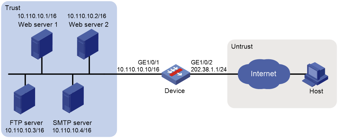
As shown in Figure 13, two Web servers, one FTP server and one SMTP server, are in the internal network to provide services for external users. The internal network address is 10.110.0.0/16. The company has three public IP addresses from 202.38.1.1/24 to 202.38.1.3/24.
Configure the NAT Server feature to allow the external user to access the internal servers with public address 202.38.1.1/24.
Procedure
1. Assign IP addresses to interfaces:
# Assign an IP address to interface GigabitEthernet 1/0/1.
<Device> system-view
[Device] interface gigabitethernet 1/0/1
[Device-GigabitEthernet1/0/1] ip address 10.110.10.10 16
[Device-GigabitEthernet1/0/1] quit
# Assign IP addresses to other interfaces in the same way. (Details not shown.)
2. Add interfaces to security zones.
[Device] security-zone name trust
[Device-security-zone-Trust] import interface gigabitethernet 1/0/1
[Device-security-zone-Trust] quit
[Device] security-zone name untrust
[Device-security-zone-Untrust] import interface gigabitethernet 1/0/2
[Device-security-zone-Untrust] quit
3. Configure a security policy:
# Configure a rule named untrust-trust to permit the packets from the host to the servers.
[Device] security-policy ip
[Device-security-policy-ip] rule name untrust-trust
[Device-security-policy-ip-1-untrust-trust] source-zone untrust
[Device-security-policy-ip-1-untrust-trust] destination-zone trust
[Device-security-policy-ip-1-untrust-trust] destination-ip-host 10.110.10.1
[Device-security-policy-ip-1-untrust-trust] destination-ip-host 10.110.10.2
[Device-security-policy-ip-1-untrust-trust] destination-ip-host 10.110.10.3
[Device-security-policy-ip-1-untrust-trust] destination-ip-host 10.110.10.4
[Device-security-policy-ip-1-untrust-trust] action pass
[Device-security-policy-ip-1-untrust-trust] quit
[Device-security-policy-ip] quit
4. Configure NAT:
# Configure service object groups for FTP, Web, and SMTP services.
[Device] object-group service service1
[Device-obj-grp-service-service1] service tcp destination eq 21
[Device-obj-grp-service-service1] quit
[Device] object-group service service2
[Device-obj-grp-service-service2] service tcp destination eq 80
[Device-obj-grp-service-service2] quit
[Device] object-group service service3
[Device-obj-grp-service-service3] service tcp destination eq 8080
[Device-obj-grp-service-service3] quit
[Device] object-group service service4
[Device-obj-grp-service-service4] service tcp destination eq 25
[Device-obj-grp-service-service4] quit
# Configure global NAT rules to allow external users to access the internal servers.
[Device] nat global-policy
[Device-nat-global-policy] rule name rule1
[Device-nat-global-policy-rule-rule1] destination-ip host 202.38.1.1
[Device-nat-global-policy-rule-rule1] source-zone untrust
[Device-nat-global-policy-rule-rule1] service service1
[Device-nat-global-policy-rule-rule1] action dnat ip-address 10.110.10.3 local-port 21
[Device-nat-global-policy-rule-rule1] quit
[Device-nat-global-policy] rule name rule2
[Device-nat-global-policy-rule-rule2] destination-ip host 202.38.1.1
[Device-nat-global-policy-rule-rule2] source-zone untrust
[Device-nat-global-policy-rule-rule2] service service2
[Device-nat-global-policy-rule-rule2] action dnat ip-address 10.110.10.1 local-port 80
[Device-nat-global-policy-rule-rule2] quit
[Device-nat-global-policy] rule name rule3
[Device-nat-global-policy-rule-rule3] destination-ip host 202.38.1.1
[Device-nat-global-policy-rule-rule3] source-zone untrust
[Device-nat-global-policy-rule-rule3] service service3
[Device-nat-global-policy-rule-rule3] action dnat ip-address 10.110.10.2 local-port 80
[Device-nat-global-policy-rule-rule3] quit
[Device-nat-global-policy] rule name rule4
[Device-nat-global-policy-rule-rule4] destination-ip host 202.38.1.1
[Device-nat-global-policy-rule-rule4] source-zone untrust
[Device-nat-global-policy-rule-rule4] service service4
[Device-nat-global-policy-rule-rule4] action dnat ip-address 10.110.10.4 local-port 25
[Device-nat-global-policy-rule-rule4] quit
[Device-nat-global-policy] quit
Verifying the configuration
# Verify that the host on the external network can access the internal servers by using the public addresses. (Details not shown.)
# Display all NAT configuration and statistics.
[Device] display nat all
NAT global-policy information:
Totally 4 NAT global-policy rules.
Rule name: rule1
Type : nat
DestIP address : 202.38.1.1
Source-zone name : untrust
Service object group : service1
DNAT action:
IPv4 address: 10.110.10.3
Port: 21
NAT counting : 0
Config status: Active
Rule name: rule2
Type : nat
DestIP address : 202.38.1.1
Source-zone name : untrust
Destination-zone name : trust
Service object group : service2
DNAT action:
IPv4 address: 10.110.10.1
Port: 80
NAT counting : 0
Config status: Active
Rule name: rule3
Type : nat
DestIP address : 202.38.1.1
Source-zone name : untrust
Destination-zone name : trust
Service object group : service3
DNAT action:
IPv4 address: 10.110.10.2
Port: 80
NAT counting : 0
Config status: Active
Rule name: rule4
Type : nat
DestIP address : 202.38.1.1
Source-zone name : untrust
Destination-zone name : trust
Service object group : service4
DNAT action:
IPv4 address: 10.110.10.4
Port: 25
NAT counting : 0
Config status: Active
NAT logging:
Log enable : Disabled
Flow-begin : Disabled
Flow-end : Disabled
Flow-active : Disabled
Port-block-assign : Disabled
Port-block-withdraw : Disabled
Alarm : Disabled
NO-PAT IP usage : Disabled
NAT mapping behavior:
Mapping mode : Address and Port-Dependent
ACL : ---
Config status: Active
NAT ALG:
DNS : Enabled
FTP : Enabled
H323 : Disabled
ICMP-ERROR : Enabled
ILS : Disabled
MGCP : Disabled
NBT : Disabled
PPTP : Enabled
RTSP : Enabled
RSH : Disabled
SCCP : Disabled
SIP : Disabled
SQLNET : Disabled
TFTP : Disabled
XDMCP : Disabled
Static NAT load balancing: Disabled
# Display NAT sessions that are generated when Host accesses the FTP server.
[Device] display nat session verbose
Slot 1:
Initiator:
Source IP/port: 202.38.1.2/52802
Destination IP/port: 202.38.1.1/21
DS-Lite tunnel peer: -
VPN instance/VLAN ID/Inline ID: -/-/-
Protocol: TCP(6)
Inbound interface: GigabitEthernet1/0/2
Source security zone: Untrust
Responder:
Source IP/port: 10.110.10.3/21
Destination IP/port: 202.38.1.2/52802
DS-Lite tunnel peer: -
VPN instance/VLAN ID/Inline ID: -/-/-
Protocol: TCP(6)
Inbound interface: GigabitEthernet1/0/1
Source security zone: Trust
State: TCP_ESTABLISHED
Application: FTP
Rule ID: -/-/-
Rule name:
Start time: 2017-05-21 11:13:39 TTL: 3597s
Initiator->Responder: 7 packets 313 bytes
Responder->Initiator: 6 packets 330 bytes
Total sessions found: 1
Example: Configuring NAT Server for external-to-internal access through domain name (non-overlapping addresses)
Network configuration
As shown in Figure 14, Web server at 10.110.10.2/24 in the internal network provides services for external users. A DNS server at 10.110.10.3/24 is used to resolve the domain name of the Web server. The company has two public IP addresses: 202.38.1.2 and 202.38.1.3.
Configure NAT Server to allow external users to access the internal Web server by using the domain name.

Requirements analysis
To meet the network requirements, you must perform the following tasks:
· Configure a NAT server mapping to map the private IP address and port of the DNS server to a public address and port. The mapping allows the external host to access the internal DNS server for domain name resolution.
· Enable ALG for DNS and configure outbound dynamic NAT to translate the private IP address of the Web server in the payload of the DNS response packet into a public IP address.
Procedure
1. Assign IP addresses to interfaces:
# Assign an IP address to interface GigabitEthernet 1/0/1.
<Device> system-view
[Device] interface gigabitethernet 1/0/1
[Device-GigabitEthernet1/0/1] ip address 10.110.10.1 24
[Device-GigabitEthernet1/0/1] quit
# Assign IP addresses to other interfaces in the same way. (Details not shown.)
2. Add interfaces to security zones.
[Device] security-zone name trust
[Device-security-zone-Trust] import interface gigabitethernet 1/0/1
[Device-security-zone-Trust] quit
[Device] security-zone name untrust
[Device-security-zone-Untrust] import interface gigabitethernet 1/0/2
[Device-security-zone-Untrust] quit
3. Configure a security policy:
# Configure a rule named untrust-trust to permit the packets from the host to the servers.
[Device] security-policy ip
[Device-security-policy-ip] rule name untrust-trust
[Device-security-policy-ip-1-untrust-trust] source-zone untrust
[Device-security-policy-ip-1-untrust-trust] destination-zone trust
[Device-security-policy-ip-1-untrust-trust] destination-ip-host 10.110.10.2
[Device-security-policy-ip-1-untrust-trust] destination-ip-host 10.110.10.3
[Device-security-policy-ip-1-untrust-trust] destination-ip-host 10.110.10.4
[Device-security-policy-ip-1-untrust-trust] action pass
[Device-security-policy-ip-1-untrust-trust] quit
[Device-security-policy-ip] quit
4. Configure NAT:
# Enable NAT with ALG for DNS.
[Device] nat alg dns
# Create an address group.
[Device] nat address-group 1
[Device-address-group-1] address 202.38.1.3 202.38.1.3
[Device-address-group-1] quit
# Create service object group service1 for DNS service.
[Device] object-group service service1
[Device-obj-grp-service-service1] service tcp destination eq 53
[Device-obj-grp-service-service1] service udp destination eq 53
[Device-obj-grp-service-service1] quit
# Configure a global NAT rule to map the address 202.38.1.1 to 10.110.10.3. External users can access the internal DNS server.
[Device] nat global-policy
[Device-nat-global-policy] rule name rule1
[Device-nat-global-policy-rule-rule1] source-zone untrust
[Device-nat-global-policy-rule-rule1] destination-ip host 202.38.1.2
[Device-nat-global-policy-rule-rule1] service service1
[Device-nat-global-policy-rule-rule1] action dnat ip-address 10.110.10.3 local-port 53
[Device-nat-global-policy-rule-rule1] quit
# Configure a global NAT rule. Use the address in address group 1 to translate the private address in DNS response payload, and allow reversible NAT.
[Device-nat-global-policy] rule name rule2
[Device-nat-global-policy-rule-rule2] source-ip host 10.110.10.2
[Device-nat-global-policy-rule-rule2] source-zone trust
[Device-nat-global-policy-rule-rule2] destination-zone untrust
[Device-nat-global-policy-rule-rule2] action snat address-group 1 no-pat reversible
[Device-nat-global-policy-rule-rule2] quit
[Device-nat-global-policy] quit
Verifying the configuration
# Verify that the host on the external network can access the internal Web server by using the server's domain name. (Details not shown.)
# Display all NAT configuration and statistics.
[Device] display nat all
NAT address group information:
Totally 1 NAT address groups.
Address group ID: 1
Port range: 1-65535
Address information:
Start address End address
202.38.1.3 202.38.1.3
NAT global-policy information:
Totally 2 NAT global-policy rules.
Rule name: rule1
Type : nat
DestIP address : 202.38.1.2
Source-zone name : untrust
Service object group : service1
DNAT action:
IPv4 address: 10.110.10.3
Port: 53
NAT counting : 0
Config status: Active
Rule name: rule2
Type : nat
SrcIP address : 10.110.10.2
Source-zone name : trust
Destination-zone name : untrust
SNAT action:
Address group ID: 1
NO-PAT: Y
Reversible: Y
Port-preserved: N
NAT counting : 0
Config status: Active
NAT logging:
Log enable : Disabled
Flow-begin : Disabled
Flow-end : Disabled
Flow-active : Disabled
Port-block-assign : Disabled
Port-block-withdraw : Disabled
Alarm : Disabled
NO-PAT IP usage : Disabled
NAT mapping behavior:
Mapping mode : Address and Port-Dependent
ACL : ---
Config status: Active
NAT ALG:
DNS : Enabled
FTP : Enabled
H323 : Disabled
ICMP-ERROR : Enabled
ILS : Disabled
MGCP : Disabled
NBT : Disabled
PPTP : Enabled
RTSP : Enabled
RSH : Disabled
SCCP : Disabled
SIP : Disabled
SQLNET : Disabled
TFTP : Disabled
XDMCP : Disabled
Static NAT load balancing: Disabled
# Display NAT sessions that are generated when Host accesses Web server.
[Device] display nat session verbose
Slot 1:
Initiator:
Source IP/port: 200.1.1.2/1694
Destination IP/port: 202.38.1.3/8080
DS-Lite tunnel peer: -
VPN instance/VLAN ID/Inline ID: -/-/-
Protocol: TCP(6)
Inbound interface: GigabitEthernet1/0/2
Source security zone: Untrust
Responder:
Source IP/port: 10.110.10.2/8080
Destination IP/port: 200.1.1.2/1694
DS-Lite tunnel peer: -
VPN instance/VLAN ID/Inline ID: -/-/-
Protocol: TCP(6)
Inbound interface: GigabitEthernet1/0/1
Source security zone: Trust
State: TCP_ESTABLISHED
Application: HTTP
Rule ID: -/-/-
Rule name:
Start time: 2017-06-15 14:53:29 TTL: 3597s
Initiator->Responder: 7 packets 308 bytes
Responder->Initiator: 5 packets 312 bytes
Total sessions found: 1
Example: Configuring NAT hairpin in P2P mode
Network configuration
In the P2P application, internal clients must register their IP address to the external server and the server records the registered IP addresses and port numbers of the internal clients. An internal client must request the IP address and port number of another client from the external server before accessing the client.
Configure NAT hairpin so that:
· The internal clients can register the same public address to the external server.
· The internal clients can access each other through the IP address and port number obtained from the server.
Figure 15 Network diagram

Requirements analysis
To meet the network requirements, you must perform the following tasks:
· Configure outbound dynamic PAT on the NAT device, so the internal clients can access the external server for registration.
· Configure the mapping behavior for PAT as Endpoint-Independent Mapping because the registered IP address and port number should be accessible for any source address.
Procedure
1. Assign IP addresses to interfaces:
# Assign an IP address to interface GigabitEthernet 1/0/1.
<Device> system-view
[Device] interface gigabitethernet 1/0/1
[Device-GigabitEthernet1/0/1] ip address 192.168.1.1 24
[Device-GigabitEthernet1/0/1] quit
# Assign IP addresses to other interfaces in the same way. (Details not shown.)
2. Add interfaces to security zones.
[Device] security-zone name trust
[Device-security-zone-Trust] import interface gigabitethernet 1/0/1
[Device-security-zone-Trust] quit
[Device] security-zone name untrust
[Device-security-zone-Untrust] import interface gigabitethernet 1/0/2
[Device-security-zone-Untrust] quit
3. Configure settings for routing.
This example configures a static route, and the next hop in the routes is 202.38.1.1.
[Device] ip route-static 200.2.2.0 24 202.38.1.1
4. Configure a security policy:
# Configure a rule named trust-untrust to permit the packets from the clients to the server.
[Device] security-policy ip
[Device-security-policy-ip] rule name trust-untrust
[Device-security-policy-ip-1-trust-untrust] source-zone trust
[Device-security-policy-ip-1-trust-untrust] destination-zone untrust
[Device-security-policy-ip-1-trust-untrust] source-ip-subnet 192.168.1.0 24
[Device-security-policy-ip-1-trust-untrust] destination-ip-host 200.2.2.2
[Device-security-policy-ip-1-trust-untrust] action pass
[Device-security-policy-ip-1-trust-untrust] quit
# Configure a rule named trust-trust to permit the packets between the clients in the Trust security zone.
[Device-security-policy-ip] rule name trust-trust
[Device-security-policy-ip-2-trust-trust] source-zone trust
[Device-security-policy-ip-2-trust-trust] destination-zone trust
[Device-security-policy-ip-2-trust-trust] source-ip-host 202.38.1.3
[Device-security-policy-ip-2-trust-trust] destination-ip-subnet 192.168.1.0 24
[Device-security-policy-ip-2-trust-trust] action pass
[Device-security-policy-ip-2-trust-trust] quit
[Device-security-policy-ip] quit
5. Configure NAT:
# Configure address object group obj1 to identify packets from subnet 192.168.1.0/24.
[Device] object-group ip address obj1
[Device-obj-grp-ip-obj1] network subnet 192.168.1.0 24
[Device-obj-grp-ip-obj1] quit
# Configure a NAT rule for the global policy with Easy IP. IP address 202.38.1.1 is used as the public address for the source address translation of the packets from internal to external.
[Device] nat global-policy
[Device-nat-global-policy] rule name rule1
[Device-nat-global-policy-rule-rule1] source-zone trust
[Device-nat-global-policy-rule-rule1] destination-zone untrust
[Device-nat-global-policy-rule-rule1] source-ip obj1
[Device-nat-global-policy-rule-rule1] action snat easy-ip
[Device-nat-global-policy-rule-rule1] quit
[Device-nat-global-policy] quit
# Configure ACL 2000 to identify packets from subnet 192.168.1.0/24 to be translated.
[Device] acl basic 2000
[Device-acl-ipv4-basic-2000] rule permit source 192.168.1.0 0.0.0.255
[Device-acl-ipv4-basic-2000] quit
# Configure the Endpoint-Independent Mapping mode for PAT. For packets with the same source address and port number and permitted by ACL 2000, the source address and port number are translated to the same public address and port number.
[Device] nat mapping-behavior endpoint-independent acl 2000
Verifying the configuration
# Verify that Host A, Host B, and Host C can access each other after they register their IP addresses and port numbers to the external server. (Details not shown.)
# Display all NAT configuration and statistics.
[Device] display nat all
NAT global-policy information:
Totally 2 NAT global-policy rules.
Rule name: rule1
Type : nat
SrcIP object group : obj1
Source-zone name : trust
Destination-zone name : untrust
SNAT action:
Easy-IP
Reversible: N
Port-preserved: N
NAT counting : 0
Config status: Active
NAT logging:
Log enable : Disabled
Flow-begin : Disabled
Flow-end : Disabled
Flow-active : Disabled
Port-block-assign : Disabled
Port-block-withdraw : Disabled
Alarm : Disabled
NO-PAT IP usage : Disabled
NAT mapping behavior:
Mapping mode : Endpoint-Independent
ACL : 2000
Config status: Active
NAT ALG:
DNS : Enabled
FTP : Enabled
H323 : Disabled
ICMP-ERROR : Enabled
ILS : Disabled
MGCP : Disabled
NBT : Disabled
PPTP : Enabled
RTSP : Enabled
RSH : Disabled
SCCP : Disabled
SIP : Disabled
SQLNET : Disabled
TFTP : Disabled
XDMCP : Disabled
Static NAT load balancing: Disabled
# Display NAT sessions that are generated when Client A accesses Client B.
[Device] display nat session verbose
Slot 1:
Initiator:
Source IP/port: 192.168.1.3/44929
Destination IP/port: 202.38.1.3/1
DS-Lite tunnel peer: -
VPN instance/VLAN ID/Inline ID: -/-/-
Protocol: UDP(17)
Inbound interface: GigabitEthernet1/0/1
Source security zone: Trust
Responder:
Source IP/port: 192.168.1.2/69
Destination IP/port: 202.38.1.3/1024
DS-Lite tunnel peer: -
VPN instance/VLAN ID/Inline ID: -/-/-
Protocol: UDP(17)
Inbound interface: GigabitEthernet1/0/1
Source security zone: Trust
State: UDP_READY
Application: TFTP
Rule ID: -/-/-
Rule name:
Start time: 2012-08-15 15:53:36 TTL: 46s
Initiator->Responder: 1 packets 56 bytes
Responder->Initiator: 1 packets 72 bytes
Total sessions found: 1
Example: Configuring the global NAT policy for NAT444 dynamic port mapping
Network configuration
As shown in Figure 16, a company uses private IP address on network 192.168.0.0/16 and public IP addresses 202.38.1.2 and 202.38.1.3. Configure the global NAT policy to meet the following requirements:
· Only users on subnet 192.168.1.0/24 can use public IP addresses 202.38.1.2 and 202.38.1.3 to access the server at 200.2.2.1 on the Internet.
· The port range for the public IP addresses is 1024 to 65535.
· The port block size is 300.
· If the ports in the assigned port block are all used, extend another port block for users.
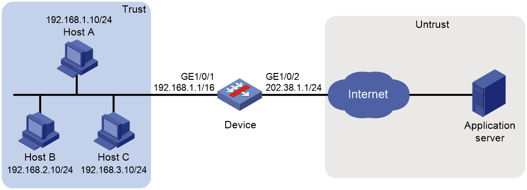
Procedure
1. Assign IP addresses to interfaces:
# Assign an IP address to interface GigabitEthernet 1/0/1.
<Device> system-view
[Device] interface gigabitethernet 1/0/1
[Device-GigabitEthernet1/0/1] ip address 192.168.1.1 16
[Device-GigabitEthernet1/0/1] quit
# Assign IP addresses to other interfaces in the same way. (Details not shown.)
2. Add interfaces to security zones.
[Device] security-zone name trust
[Device-security-zone-Trust] import interface gigabitethernet 1/0/1
[Device-security-zone-Trust] quit
[Device] security-zone name untrust
[Device-security-zone-Untrust] import interface gigabitethernet 1/0/2
[Device-security-zone-Untrust] quit
3. Configure settings for routing.
This example configures a static route, and the next hop in the routes is 202.38.1.20.
[Device] ip route-static 200.2.2.1 32 202.38.1.20
4. Configure a security policy:
# Configure a rule named trust-untrust to permit the packets from the hosts to the application server.
[Device] security-policy ip
[Device-security-policy-ip] rule name trust-untrust
[Device-security-policy-ip-1-trust-untrust] source-zone trust
[Device-security-policy-ip-1-trust-untrust] destination-zone untrust
[Device-security-policy-ip-1-trust-untrust] source-ip-subnet 192.168.1.0 24
[Device-security-policy-ip-1-trust-untrust] destination-ip-host 200.2.2.1
[Device-security-policy-ip-1-trust-untrust] action pass
[Device-security-policy-ip-1-trust-untrust] quit
[Device-security-policy-ip] quit
5. Configure NAT:
# Create NAT address group 0.
[Device] nat address-group 0
# Add public IP addresses 202.38.1.2 and 202.38.1.3 to the NAT address group.
[Device-address-group-0] address 202.38.1.2 202.38.1.3
# Configure the port range as 1024 to 65535.
[Device-address-group-0] port-range 1024 65535
# Set the port block size to 300 and the extended port block number to 1.
[Device-address-group-0] port-block block-size 300 extended-block-number 1
[Device-address-group-0] quit
# Configure address object group obj1 to identify packets from subnet 192.168.1.0/24.
[Device] object-group ip address obj1
[Device-obj-grp-ip-obj1] network subnet 192.168.1.0 24
[Device-obj-grp-ip-obj1] quit
# Configure a NAT rule for the global policy, and specify address object group obj1 as the packet match criterion and use NAT address group 0 for source address and port translation.
[Device] nat global-policy
[Device-nat-global-policy] rule name rule1
[Device-nat-global-policy-rule-rule1] source-ip obj1
[Device-nat-global-policy-rule-rule1] action snat address-group 0
Verifying the configuration
# Verify that Host A can access external servers, but Host B and Host C cannot. (Details not shown.)
# Display all NAT configurations and statistics.
[Device]display nat all
NAT address group information:
Totally 1 NAT address groups.
Address group ID: 0
Port range: 1024-65535
Blade-load-sharing-group: Blade4fw-m90001
Port block size: 300
Extended block number: 1
Address information:
Start address End address
202.38.1.2 202.38.1.3
Exclude address information:
Start address End address
NAT global-policy information:
Totally 1 NAT global-policy rules.
Rule name: rule1
SrcIP object group : obj1
SNAT action:
Address group ID: 0
NO-PAT: N
Reversible: N
Port-preserved: N
NAT counting : 0
Config status: Active
NAT logging:
Log enable : Disabled
Flow-begin : Disabled
Flow-end : Disabled
Flow-active : Disabled
Port-block-assign : Disabled
Port-block-withdraw : Disabled
Alarm : Disabled
NO-PAT IP usage : Disabled
NAT mapping behavior:
Mapping mode : Address and Port-Dependent
ACL : ---
Config status: Active
NAT ALG:
DNS : Enabled
FTP : Enabled
H323 : Disabled
ICMP-ERROR : Enabled
ILS : Disabled
MGCP : Disabled
NBT : Disabled
PPTP : Enabled
RTSP : Enabled
RSH : Disabled
SCCP : Disabled
SIP : Disabled
SQLNET : Disabled
TFTP : Disabled
XDMCP : Disabled
Static NAT load balancing: Disabled
# Display NAT statistics.
[Device] display nat statistics
Slot 1:
Total session entries: 1
Session creation rate: 0
Total EIM entries: 0
Total inbound NO-PAT entries: 0
Total outbound NO-PAT entries: 0
Total static port block entries: 0
Total dynamic port block entries: 430
Active static port block entries: 0
Active dynamic port block entries: 1
# Display dynamic port block entries.
[Device] display nat port-block dynamic
Slot 1:
Local VPN Local IP Global IP Port block Connections
--- 192.168.1.10 202.38.1.2 45724-46023 1
Total mappings found: 1
Configuring interface-based NAT
Restrictions and guidelines: interface-based NAT configuration
The general restrictions and guidelines are as follows:
· You can use an ACL in a NAT rule to identify the IP addresses to be translated. The match criteria include the source IP address, source port number, destination IP address, destination port number, transport layer protocol, and VPN instance.
· If NAT is configured on only one output interface in a dual uplink network, do not add the two output interfaces to the same security zone. Doing so will cause communication interruption. For more information about security zone, see Security Configuration Guide.
· As a best practice, configure interface-based NAT on a logical interface of the device with multiple slots so that all packets to be NATed can be processed on the logical interface. If you fail to do so, the slots for input and output packets might be different and address translation will fail.
· If you perform all the translation methods on an interface, the NAT rules are sorted in the following descending order:
a. NAT Server.
b. Static NAT.
c. NAT444 static port blocking mapping.
d. Dynamic NAT, NAT444 dynamic port block mapping, and DS-Lite B4 address translation.
Dynamic NAT, NAT444 dynamic port block mapping, and DS-Lite B4 address translation have the same priority. Dynamic NAT rules and NAT444 dynamic port block mapping rules are sorted in descending order of ACL numbers and are effective for IPv4 packets. DS-Lite B4 address translation rules are effective for IPv6 packets.
Interface-based NAT tasks at a glance
To configure NAT, perform the following tasks:
1. Configuring an address translation method on an interface
¡ Configuring static NAT on an interface
¡ Configuring dynamic NAT on an interface
¡ Configuring NAT server mappings on an interface
¡ Configuring NAT444 on an interface
¡ Configuring DS-Lite B4 address translation on an interface
¡ Configuring the interface-based NAT policy
The NAT policy allows flexible address translation rules for multiple interfaces.
2. (Optional.) Using failover groups for dynamic NAT
You have to configure a QoS policy to redirect the traffic to the failover groups on the device. For information about failover groups, see Virtual Technologies Configuration Guide.
3. (Optional.) Configuring NAT hairpin
4. (Optional.) Configuring NAT ALG
1. (Optional.) Configuring NAT load sharing features
¡ Enabling static NAT load sharing
¡ Specifying a load sharing group for NAT
2. (Optional.) Configuring NAT maintenance
¡ Configuring periodic NAT statistics collection
¡ Enabling statistics collection for NAT session creation rate
¡ Specifying a probe method for detecting reachability of NAT address group members
¡ Enabling sending ICMP error messages for NAT failures
3. (Optional.) Configuring NAT logging
4. (Optional.) Enabling sending ICMP error messages for NAT failures
5. (Optional.) Configuring NAT in specific networks
¡ Enabling NAT reply redirection
¡ Enabling the deletion of timestamps in TCP SYN and SYN ACK packets
¡ Enabling NAT session recreation after link switchover
Configuring static NAT on an interface
Restrictions and guidelines for static NAT configuration on an interface
Typically, configure inbound static NAT with outbound dynamic NAT, NAT Server, or outbound static NAT to implement source address translation and destination address translation.
Prerequisites
Before configuring static NAT, you must perform the following tasks:
· Configure an ACL to identify the IP addresses to be translated. For more information about ACLs, see ACL and QoS Configuration Guide.
· Manually add a route for inbound static NAT. Use local-ip or local-network as the destination address, and use global-ip, an address in global-network, or the next hop directly connected to the output interface as the next hop.
Configuring outbound one-to-one static NAT
About this task
For address translation from a private IP address to a public IP address, configure outbound one-to-one static NAT on the interface connected to the external network.
· When the source IP address of an outgoing packet matches the local-ip, the source IP address is translated into the global-ip.
· When the destination IP address of an incoming packet matches the global-ip, the destination IP address is translated into the local-ip.
Restrictions and guidelines
If multiple outbound one-to-one static mappings uses different ACL rules, you can map a private address to different public addresses.
If you do not specify the acl keyword for a one-to-one mapping NAT rule, the rule can process reversible traffic. If the acl keyword is specified for the NAT rule, you must specify the reversible keyword for the rule to process reversible traffic.
Procedure
1. Enter system view.
system-view
2. Configure a one-to-one mapping for outbound static NAT.
nat static outbound local-ip [ vpn-instance local-vpn-instance-name ] global-ip [ vpn-instance global-vpn-instance-name ] [ acl { ipv4-acl-number | name ipv4-acl-name } [ reversible ] ] [ vrrp virtual-router-id ] [ rule rule-name ] [ priority priority ] [ disable ] [ counting ] [ description text ]
3. (Optional.) Rearrange outbound one-to-one mapping NAT rules to adjust their priorities.
nat static outbound rule move nat-rule-name1 { after | before } nat-rule-name2
4. Enter interface view.
interface interface-type interface-number
5. Enable static NAT on the interface.
nat static enable
By default, static NAT is disabled.
Configuring outbound net-to-net static NAT
About this task
For address translation from a private network to a public network, configure outbound net-to-net static NAT on the interface connected to the external network.
· When the source IP address of an outgoing packet matches the private address range, the source IP address is translated into a public address in the public address range.
· When the destination IP address of an incoming packet matches the public address range, the destination IP address is translated into a private address in the private address range.
Procedure
1. Enter system view.
system-view
2. Configure a net-to-net mapping for outbound static NAT.
nat static outbound net-to-net local-start-address local-end-address [ vpn-instance local-vpn-instance-name ] global global-network { mask-length | mask } [ vpn-instance global-vpn-instance-name ] [ acl { ipv4-acl-number | name ipv4-acl-name } [ reversible ] ] [ vrrp virtual-router-id ] [ rule rule-name ] [ priority priority ] [ disable ] [ counting ]
3. Enter interface view.
interface interface-type interface-number
4. Enable static NAT on the interface.
nat static enable
By default, static NAT is disabled.
Configuring object group-based outbound static NAT
About this task
Configure object group-based outbound static NAT on the interface connected to the external network to translate private IP addresses into public IP addresses.
· When the source address of an outgoing packet matches the private address object group, the source address is translated into a public address in the public address object group.
· When the destination address of an incoming packet matches the public address object group, the destination address is translated into a private address in the private address object group.
Restrictions and guidelines
If you specify the acl keyword, NAT processes only packets permitted by the ACL.
For an object group-based outbound static NAT mapping to take effect, make sure the following requirements are met:
· One address object group contains only one host object or subnet object.
· A subnet object cannot have excluded addresses.
Procedure
1. Enter system view.
system-view
2. Configure an object group-based outbound static NAT mapping.
nat static outbound object-group local-object-group-name [ vpn-instance local-vpn-instance-name ] object-group global-object-group-name [ vpn-instance global-vpn-instance-name ] [ acl { ipv4-acl-number | name ipv4-acl-name } [ reversible ] ] [ vrrp virtual-router-id ] [ disable ] [ counting ]
By default, no mappings exist.
3. Enter interface view.
interface interface-type interface-number
4. Enable static NAT on the interface.
nat static enable
By default, static NAT is disabled.
Configuring inbound one-to-one static NAT
About this task
For address translation from a public IP address to a private IP address, configure inbound one-to-one static NAT.
· When the source IP address of an incoming packet matches the global-ip, the source IP address is translated into the local-ip.
· When the destination IP address of an outgoing packet matches the local-ip, the destination IP address is translated into the global-ip.
Procedure
1. Enter system view.
system-view
2. Configure a one-to-one mapping for inbound static NAT.
nat static inbound global-ip [ vpn-instance global-vpn-instance-name ] local-ip [ vpn-instance local-vpn-instance-name ] [ acl { ipv4-acl-number | name ipv4-acl-name } [ reversible ] ] [ rule rule-name ] [ priority priority ] [ disable ] [ counting ] [ description text ]
3. Enter interface view.
interface interface-type interface-number
4. Enable static NAT on the interface.
nat static enable
By default, static NAT is disabled.
Configuring inbound net-to-net static NAT
About this task
For address translation from a public network to a private network, configure inbound net-to-net static NAT.
· When the source IP address of an incoming packet matches the public address range, the source IP address is translated into a private address in the private address range.
· When the destination IP address of an outgoing packet matches the private address range, the destination IP address is translated into a public address in the public address range.
Procedure
1. Enter system view.
system-view
2. Configure a net-to-net mapping for inbound static NAT.
nat static inbound net-to-net global-start-address global-end-address [ vpn-instance global-vpn-instance-name ] local local-network { mask-length | mask } [ vpn-instance local-vpn-instance-name ] [ acl { ipv4-acl-number | name ipv4-acl-name } [ reversible ] ] [ rule rule-name ] [ priority priority ] [ disable ] [ counting ]
3. Enter interface view.
interface interface-type interface-number
4. Enable static NAT on the interface.
nat static enable
By default, static NAT is disabled.
Configuring object group-based inbound static NAT
About this task
Configure object group-based inbound static NAT to translate public IP addresses into private IP addresses.
· When the destination address of an outgoing packet matches the private address object group, the destination address is translated into a public address in the public address object group.
· When the source address of an incoming packet matches the public address object group, the source address is translated into a private address in the private address object group.
Restrictions and guidelines
If you specify the acl keyword, NAT processes only packets permitted by the ACL.
For an object group-based inbound static NAT mapping to take effect, make sure the following requirements are met:
· One address object group contains only one host object or subnet object.
· A subnet object cannot have excluded addresses.
For an inbound static mapping, if its private IPv4 object group contains a host address, the host address cannot be on the same subnet as the interface configured with this mapping.
Procedure
1. Enter system view
system-view
2. Configure an object group-based inbound static NAT mapping.
nat static inbound object-group global-object-group-name [ vpn-instance global-vpn-instance-name ] object-group local-object-group-name [ vpn-instance local-vpn-instance-name ] [ acl { ipv4-acl-number | name ipv4-acl-name } [ reversible ] ] [ disable ] [ counting ]
By default, no NAT mappings exist.
3. Enter interface view.
interface interface-type interface-number
4. Enable static NAT on the interface.
nat static enable
By default, static NAT is disabled.
Configuring dynamic NAT on an interface
Restrictions and guidelines dynamic NAT configuration on an interface
You can configure multiple inbound or outbound dynamic NAT rules.
· A NAT rule with an ACL takes precedence over a rule without any ACL.
· If two ACL-based dynamic NAT rules are configured, the rule with the higher ACL number has higher priority.
When configuring NO-PAT and DNS ALG for internal server access through a domain name, make sure the NAT address group for NO-PAT has sufficient IP addresses. The minimum number of IP addresses must be equal to the number of security engines multiplied by the number of internal servers. For more information about security engines, see context configuration in Virtual Technologies Configuration Guide.
Prerequisites
Before configuring dynamic NAT, you must perform the following tasks:
· Configure an ACL to identify the IP addresses to be translated. For more information about ACLs, see ACL and QoS Configuration Guide.
· Determine whether to enable the Easy IP feature. If you use the IP address of an interface as the NAT address, you are configuring Easy IP.
· Determine a public IP address pool for address translation.
· Determine whether to translate port numbers. Use NO-PAT to translate only IP addresses and PAT to translate both IP addresses and port numbers.
Configuring outbound dynamic NAT
About this task
To translate private IP addresses into public IP addresses, configure outbound dynamic NAT on the interface connected to the external network.
Procedure
1. Enter system view.
system-view
2. Create a NAT address group and enter its view.
nat address-group group-id
3. Add an address range to the address group.
address start-address end-address [ name group-name ]
You can add multiple address ranges to an address group.
The address ranges must not overlap.
4. (Optional.) Exclude IP addresses from being used in address translation.
exclude-ip start-address end-address
The end-address must not be lower than the start-address. If they are the same, you specify only one IP address.
5. Return to system view.
quit
6. Enter interface view.
interface interface-type interface-number
7. Configure outbound dynamic NAT. Choose the options to configure as needed:
¡ Configure NO-PAT.
nat outbound [ ipv4-acl-number | name ipv4-acl-name ] address-group { group-id | name group-name } [ vpn-instance vpn-instance-name ] no-pat [ reversible ] [ rule rule-name ] [ priority priority ] [ disable ] [ counting ] [ description text ]
¡ Configure PAT.
nat outbound [ ipv4-acl-number | name ipv4-acl-name ][ address-group { group-id | name group-name } ] [ vpn-instance vpn-instance-name ] [ port-preserved ] [ rule rule-name ] [ priority priority ] [ disable ] [ counting ] [ description text ]
You can configure multiple outbound dynamic NAT rules on an interface.
|
Parameter |
Description |
|
address-group |
If you do not specify this keyword, the IP address of the interface is used as the NAT address. Easy IP is implemented. |
|
no-pat reversible |
If you specify these keywords, you enable reverse address translation. Reverse address translation uses existing NO-PAT entries to translate the destination address for connections actively initiated from the external network to the internal network. The destination address is translated into the private IP address in the matching NO-PAT entry. |
8. (Optional.) Configure a PAT mapping mode.
a. Return to system view.
quit
b. Configure a PAT mapping mode.
nat mapping-behavior endpoint-independent [ acl { ipv4-acl-number | name ipv4-acl-name } ]
The default mapping mode is Address and Port-Dependent Mapping.
This command takes effect only on outbound dynamic NAT for PAT.
9. (Optional.) Rearrange outbound dynamic NAT rules to adjust their priorities.
nat outbound rule move nat-rule-name1 { after | before } nat-rule-name2
Configuring inbound dynamic NAT
Restrictions and guidelines
Do not configure inbound dynamic NAT alone. Typically, inbound dynamic NAT functions with outbound dynamic NAT, NAT Server, or outbound static NAT to implement source address translation and destination address translation.
As a best practice, manually create a route because it takes time to automatically add routes.
Procedure
1. Enter system view.
system-view
2. Create a NAT address group and enter its view.
nat address-group group-id
3. Add an address range to the address group.
address start-address end-address [ name group-name ]
You can add multiple address ranges to an address group.
The address ranges in address groups must not overlap.
4. (Optional.) Exclude IP addresses from being used in address translation.
exclude-ip start-address end-address
The end-address must not be lower than the start-address. If they are the same, you specify only one IP address.
5. Return to system view.
quit
6. Enter interface view.
interface interface-type interface-number
7. Configure inbound dynamic NAT.
nat inbound { ipv4-acl-number | name ipv4-acl-name } address-group { group-id | name group-name } [ vpn-instance vpn-instance-name ] [ no-pat [ reversible ] [ add-route ] ] [ rule rule-name ] [ priority priority ] [ disable ] [ counting ] [ description text ]
You can configure multiple inbound dynamic NAT rules on an interface.
|
Parameter |
Description |
|
no-pat reversible |
If you specify these keywords, you enable reverse address translation. Reverse address translation uses existing NO-PAT entries to translate the destination address for connections actively initiated from the external network to the internal network. The destination address is translated into the private IP address in the matching NO-PAT entry. |
|
add-route |
This keyword enables the device to automatically add a route destined for the private address when an inbound dynamic NAT rule is matched. The output interface is the NAT interface, and the next hop is the source address before translation. If you do not specify this keyword, you must manually add the route. |
8. (Optional.) Rearrange inbound dynamic NAT rules to adjust their priorities.
nat inbound rule move nat-rule-name1 { after | before } nat-rule-name2
Configuring NAT server mappings on an interface
About NAT server mappings
Typically, the NAT Server feature is configured on the interface connected to the external network to allow servers in the internal network or an MPLS VPN instance to provide services for external users. A NAT server mapping (also called NAT server rule) maps a public IP address and port number to the private IP address and port number of the internal server.
The NAT Server feature can be implemented by configuring the following server mappings:
· Common NAT server mapping—Maps the private IP address and the port number of the internal server to a public IP address and a port number. This method allows external hosts to access the internal server by using the specified public IP address.
· Load sharing NAT server mapping—You can add multiple internal servers to an internal server group so that these servers provide the same service for external hosts. The NAT device chooses one internal server based on the weight and number of connections of the servers to respond to a request from an external host to the public address of the internal server group.
· ACL-based NAT server mapping—An extension of common NAT server mapping. A common NAT server mapping maps the private IP address of the internal server to a single public IP address. An ACL-based NAT server mapping maps the private IP address of the internal server to a set of public IP addresses defined by an ACL. If the destination address of a packet matches a permit rule in the ACL, the destination address is translated into the private IP address of the internal server.
· Object group-based server mapping—Uses the address object group and service object group as the packet match criteria. The destination IP addresses and port numbers of the matching packets are translated to the same address and port number. For more information about object groups, see Security Configuration Guide.
Restrictions and guidelines for NAT server mapping configuration on an interface
In a scenario where Real-Time Transport Protocol (RTP) is used to transmit audio and video flows, the server and client send Real-Time Control Protocol (RTCP) packets periodically during the course of a session. If the server is on the private network, you must specify the reversible keyword when executing the nat server command. If you do not specify the reversible keyword, the NAT device discards the RTCP packets sent to the client on the public network and audio and video transmission services fail.
When you configure a load shared NAT server mapping, you must make sure a user uses the same public address and public port to access the same service on an internal server. For this purpose, make sure value N in the following mappings is equal to or less than the number of servers in the internal server group:
· One public address and N consecutive public port numbers are mapped to one internal server group.
· N consecutive public addresses and one public port number are mapped to one internal server group.
When you roll back configuration in a version that supports the automatic NAT rule name assignment, a rollback failure message is displayed if the no automatically assigned names exist in the replacement configuration file.
For example, the system compares the configuration in the replacement configuration file and the configuration after the rollback and displays a rollback failure message in the following conditions:
· The replacement configuration file has the following configuration: nat server global 112.1.1.1 inside 192.168.20.1.
· The NAT rule configuration after the rollback is nat server global 112.1.1.1 inside 192.168.20.1 rule NAT server rule_10 (NAT server rule_10 indicating an NAT rule name automatically assigned by the system).
In this case, the NAT rule configuration in the replacement configuration file has been issued and you can ignore this failure message.
Configuring common NAT server mappings
1. Enter system view.
system-view
2. Enter interface view.
interface interface-type interface-number
3. Configure common NAT server mappings. Choose the options to configure as needed:
¡ A single public address with a single or no public port:
nat server [ protocol pro-type ] global { global-address | current-interface | interface interface-type interface-number } [ global-port ] [ vpn-instance global-vpn-instance-name ] inside local-address [ local-port ] [ vpn-instance local-vpn-instance-name ] [ acl { ipv4-acl-number | name ipv4-acl-name } ] [ reversible ] [ vrrp virtual-router-id ] [ rule rule-name ] [ disable ] [ counting ] [ description text ]
¡ A single public address with consecutive public ports:
nat server protocol pro-type global { global-address | current-interface | interface interface-type interface-number } global-port1 global-port2 [ vpn-instance global-vpn-instance-name ] inside { { local-address | local-address1 local-address2 } local-port | local-address local-port1 local-port2 } [ vpn-instance local-vpn-instance-name ] [ acl { ipv4-acl-number | name ipv4-acl-name } ] [ vrrp virtual-router-id ] [ rule rule-name ] [ disable ] [ counting ] [ description text ]
¡ Consecutive public addresses with no public port:
nat server protocol pro-type global global-address1 global-address2 [ vpn-instance global-vpn-instance-name ] inside { local-address | local-address1 local-address2 } [ local-port ] [ vpn-instance local-vpn-instance-name ] [ acl { ipv4-acl-number | name ipv4-acl-name } ] [ vrrp virtual-router-id ] [ rule rule-name ] [ disable ] [ counting ] [ description text ]
¡ Consecutive public addresses with a single public port:
nat server protocol pro-type global global-address1 global-address2 global-port [ vpn-instance global-vpn-instance-name ] inside { local-address [ local-port1 local-port2 ] | [ local-address | local-address1 local-address2 ] [ local-port ] } [ vpn-instance local-vpn-instance-name ] [ acl { ipv4-acl-number | name ipv4-acl-name } ] [ vrrp virtual-router-id ] [ rule rule-name ] [ disable ] [ counting ] [ description text ]
You can configure multiple NAT server mappings on an interface.
Configuring load sharing NAT server mappings
1. Enter system view.
system-view
2. Create a NAT server group and enter its view.
nat server-group group-id
By default, no NAT server groups exist.
3. Add an internal server into the group.
inside ip inside-ip port port-number [ weight weight-value ]
You can add multiple internal servers to a group.
4. Return to system view.
quit
5. Enter interface view.
interface interface-type interface-number
6. Configure a load sharing NAT server mapping.
nat server protocol pro-type global { { global-address | nat server protocol pro-type global { { global-address | current-interface | interface interface-type interface-number } { global-port | global-port1 global-port2 } | global-address1 global-address2 global-port } [ vpn-instance global-vpn-instance-name ] inside server-group group-id [ vpn-instance local-vpn-instance-name ] [ acl { ipv4-acl-number | name ipv4-acl-name } ] [ vrrp virtual-router-id ] [ rule rule-name ] [ disable ] [ counting ] [ description text ]
You can configure multiple load sharing NAT server mappings on an interface.
Configuring ACL-based NAT server mappings
1. Enter system view.
system-view
2. Enter interface view.
interface interface-type interface-number
3. Configure an ACL-based NAT server mapping.
nat server global { ipv4-acl-number | name ipv4-acl-name } inside local-address [ local-port ] [ vpn-instance local-vpn-instance-name ] [ vrrp virtual-router-id ] [ rule rule-name ] [ priority priority ] [ disable ] [ counting ] [ description text ]
You can configure multiple NAT server mappings on an interface.
4. (Optional.) Rearrange ACL-based NAT server mappings to adjust their priorities.
nat server rule move nat-rule-name1 { after | before } nat-rule-name2
Configuring object group-based NAT server mappings
About this task
An object group-based NAT server mapping uses the address object group and service object group as the packet match criteria. The destination IP addresses and port numbers of the matching packets are translated to the same address and port number. For more information about object groups, see Security Configuration Guide.
When multiple object group-based NAT server mappings are configured, the mapping configured earlier has a higher priority. The match process of a packet stops when the packet matches a mapping.
Restrictions and guidelines
The private port number in the NAT server mapping takes effect only when the protocol type is TCP or UDP for the service object group used by the mapping.
One NAT server mapping supports a maximum of five address object groups and one service object group.
Prerequisites
Before you create a mapping, the IPv4 address object groups and service object group must already exist. An IPv4 address object group cannot have excluded IPv4 address configuration.
Procedure
1. Enter system view
system-view
2. Enter interface view.
interface interface-type interface-number
3. Create an object group-based NAT server mapping.
nat server rule rule-name global destination-ip object-group-name&<1-5> [ service object-group-name ] inside local-address [ local-port ] [ vrrp virtual-router-id ] [ disable ] [ counting ] [ description text ]
By default, no object group-based NAT server mapping exists.
4. Add object groups to the NAT server mapping.
nat server rule rule-name global { destination-ip object-group-name&<1-5> | service object-group-name }
You can add object groups only to existing object group-based NAT server mappings.
Configuring NAT444 on an interface
About NAT444
NAT444 provides outbound address translation, and it is configured on the interface connected to the public network. By configuring NAT444 address translation on the NAT444 gateway, multiple private IP addresses are mapped to one public IP address and a different port block is used for each private IP address
Restrictions and guidelines for NAT444 configuration on an interface
To configure dynamic port block mapping for NAT444, you must configure port block parameters in the NAT address group.
Configuring static port block mapping for NAT444
1. Enter system view.
system-view
2. Create a NAT port block group, and enter its view.
nat port-block-group group-id
3. Add a private IP address range to the port block group.
local-ip-address start-address end-address [ vpn-instance vpn-instance-name ]
You can add multiple private IP address ranges to one port block group, but they cannot overlap.
4. Add a public IP address range to the port block group.
global-ip-pool start-address end-address
You can add multiple public IP address ranges to one port block group, but they cannot overlap.
5. Configure the port range for the public IP addresses.
port-range start-port-number end-port-number
By default, the port range is 1 to 65535.
6. Set the port block size.
block-size block-size
By default, the port block size is 256.
7. Return to system view.
quit
8. Enter interface view.
interface interface-type interface-number
9. Configure a static outbound port block mapping rule on the interface.
nat outbound port-block-group group-id [ rule rule-name ] [ counting ]
By default, no port block mapping rule is configured on an interface.
You can configure multiple port block mapping rules on one interface.
10. (Optional.) Configure a PAT mapping mode.
a. Return to system view.
quit
b. Configure a PAT mapping mode.
nat mapping-behavior endpoint-independent [ acl { ipv4-acl-number | name ipv4-acl-name } ]
The default mapping mode is Address and Port-Dependent Mapping.
Configuring dynamic port block mapping for NAT444
You can use one of the following methods to add IP addresses to a NAT address group:
· Method 1—Adding one or multiple address ranges.
· Method 2—Adding the IP address of the specified interface. This method supports the cooperation between dynamic NAT port block mappings and Easy IP and supports user tracing.
Only one method is supported for a NAT address group.
Use Method 2 if the IP address after translation is the IP address of the interface connected to the external network and the IP address is dynamically obtained through DHCP. This method avoids the inaccurate NAT IP address information caused by the IP address change of the interface.
Procedure
1. Enter system view.
system-view
2. (Optional.) Configure a PAT mapping mode.
nat mapping-behavior endpoint-independent [ acl { ipv4-acl-number | name ipv4-acl-name } ]
The default mapping mode is Address and Port-Dependent Mapping.
3. Create a NAT address group, and enter its view.
nat address-group group-id [ name group-name ]
4. Add addresses to the NAT address group. Choose one option as needed:
¡ Add IP address ranges to the NAT address group.
address start-address end-address
You can add multiple public IP address ranges to an address group.
The IP address ranges in address groups cannot overlap.
Execute the following command to exclude IP addresses from being used in address translation.
exclude-ip start-address end-address
The end-address must not be lower than the start-address. If they are the same, you specify only one IP address.
¡ Add the IP address of an interface to the NAT address group.
address interface interface-type interface-number
By default, no interface address exists in the NAT address group.
You can specify only one interface for a NAT address group.
5. (Optional.) Configure the port range for the public IP addresses.
port-range start-port-number end-port-number
By default, the port range is 1 to 65535.
The configuration takes effect only on PAT translation mode.
6. Configure port block parameters.
port-block block-size block-size [ extended-block-number extended-block-number ]
The configuration takes effect only on PAT translation mode.
7. Return to system view.
quit
8. Enter interface view.
interface interface-type interface-number
9. Configure PAT for outbound dynamic NAT.
nat outbound [ ipv4-acl-number | name ipv4-acl-name ] [ address-group { group-id | name group-name } ] [ vpn-instance vpn-instance-name ] [ port-preserved ] [ rule rule-name ] [ priority priority ] [ disable ] [ counting ] [ description text ]
By default, no outbound dynamic NAT rules exist.
The port-preserved keyword does not take effect on dynamic NAT444.
10. (Optional.) Enable dynamic port block mapping synchronization.
a. Return to system view.
quit
b. Enable dynamic port block mapping synchronization.
nat port-block synchronization enable
By default, dynamic port block mapping synchronization is disabled.
Enabling port block global sharing
About this task
When multiple interfaces have dynamic NAT port block mapping configured, the interfaces might create different port block mappings for packets from the same IP address. You can use this command to configure the interfaces to use the same port block mapping for translating packets from the same IP address.
Procedure
1. Enter system view
system-view
2. Enable port block global sharing.
nat port-block global-share enable
By default, port block global sharing is disabled.
Configuring DS-Lite B4 address translation on an interface
About this task
DS-Lite B4 address translation is configured on the AFTR's interface connected to the external network. It uses an IPv6 ACL to identify packets to be NATed.
DS-Lite B4 address translation supports only the dynamic port block mapping method.
Prerequisites
Before configuring DS-Lite B4 address translation, make sure the B4 element and the AFTR can reach each other through IPv6.
Procedure
1. Enter system view.
system-view
2. (Optional.) Configure a PAT mapping mode.
nat mapping-behavior endpoint-independent [ acl { ipv4-acl-number | name ipv4-acl-name } ]
The default mapping mode is Address and Port-Dependent Mapping.
3. Create a NAT address group, and enter its view.
nat address-group group-id [ name group-name ]
4. Add a public IP address range to the NAT address group.
address start-address end-address
You can add multiple public IP address ranges to an address group.
The IP address ranges in address groups cannot overlap.
5. (Optional.) Exclude IP addresses from being used in address translation.
exclude-ip start-address end-address
The end-address must not be lower than the start-address. If they are the same, you specify only one IP address.
6. Configure the port range for the public IP addresses.
port-range start-port-number end-port-number
By default, the port range is 1 to 65535.
The configuration takes effect only on PAT translation mode.
7. Configure port block parameters.
port-block block-size block-size [ extended-block-number extended-block-number ]
By default, no port block parameters exist.
The configuration takes effect only on PAT translation mode.
8. Return to system view.
quit
9. Enter interface view.
interface interface-type interface-number
10. Configure DS-Lite B4 address translation.
nat outbound ds-lite-b4 { ipv6-acl-number | name ipv6-acl-name } address-group group-id
By default, DS-Lite B4 address translation is not configured.
11. (Optional.) Enable dynamic port block mapping synchronization.
a. Return to system view.
quit
b. Enable dynamic port block mapping synchronization.
nat port-block synchronization enable
By default, dynamic port block mapping synchronization is disabled.
Configuring the interface-based NAT policy
About the interface-based NAT policy
The interface-based NAT policy performs address translation for outgoing packets on the interfaces that the rules are applied. The NAT policy can contain a set of NAT rules. The device identifies the packets based on the object groups in the NAT rules, and translates addresses according to the method in the matching rule.
Restrictions and guidelines for interface-based NAT policy configuration
If a NAT rule does not use any object group, this rule matches all packets.
The NAT policy supports only dynamic address translation, and the policy has a higher priority than the dynamic address translation configuration on interfaces.
Creating the interface-based NAT policy
1. Enter system view
system-view
2. Create the interface-based NAT policy and enter its view.
nat policy
By default, the interface-based NAT policy does not exist.
Configuring NAT rules
Restrictions and guidelines
The NAT rules in the interface-based NAT policy are sorted in descending order of their configuration order. A rule configured earlier has a higher priority. The matching process stops when a packet matches a NAT rule. You can use the display this command to view the configuration order of the NAT rules.
Procedure
1. Enter system view.
system-view
2. Enter the interface-based NAT policy view.
nat policy
3. Create a NAT rule and enter its view.
rule name rule-name
By default, no NAT rule exists.
4. (Optional.) Configure a description for the rule.
description text
By default, a NAT rule does not have any description.
5. Apply the NAT rule to the outgoing traffic on an interface.
outbound-interface interface-type interface-name
By default, a NAT rule is not applied to the outgoing traffic on an interface.
6. Specify an object group for the NAT rule. Choose the options to configure as needed:
¡ Specify a source IP address object group.
source-ip object-group-name
The source IP address object groups is used to match the source IP address in the packet.
¡ Specify a destination IP address object group.
destination-ip object-group-name
The destination IP address object groups is used to match the destination IP address in the packet.
¡ Specify a service object group.
service object-group-name
The service object groups is used to match the service type in the packet.
By default, the NAT rule does not have any object groups.
Make sure the specified object groups already exist.
7. Specify an address translation method for the NAT rule. Choose the options to configure as needed:
¡ Specify the Easy IP method.
action easy-ip
¡ Specify the NO-NAT method.
action no-nat
¡ Specify the NO-PAT method.
action address-group { group-id | name group-name } no-pat [ reversible ]
¡ Specify the PAT method.
action address-group { group-id | name group-name } [ port-preserved ]
By default, no address translation method is specified in a NAT rule.
8. (Optional.) Enable hit counting for the NAT rule.
counting enable
By default, hit counting is disabled for the NAT rule.
Rearranging NAT rules in the policy to adjust their priority
About this task
In the interface-based NAT policy, the priority of NAT rules are determined by the configuration order. A rule configured earlier has a higher priority. You can use the rule move command to rearrange the NAT rules to adjust their priority.
Restrictions and guidelines
In the interface-based NAT policy, the priority of NAT rules of the same type are determined by the priority value. The smaller the value, the higher the priority. You can move the location of the NAT rules to adjust their priority as the following rules:
· Move the rule nat-rule-name1 to the line after the rule nat-rule-name2 (called the reference rule). The priority value of the reference rule is not changed. The priority value of the moved rule equals the priority value of the reference rule plus one.
Move the rule nat-rule-name1 to the line before the rule nat-rule-name2. The priority value of the reference rule is not changed. The priority value of the moved rule equals the priority value of the reference rule minus one.
Procedure
1. Enter system view.
system-view
2. Enter the interface-based NAT policy view.
nat policy
3. Rearrange NAT rules to change their priority.
rule move rule-name1 { after | before } [ rule-name2 ]
Disabling NAT rules
Restrictions and guidelines
This feature does not delete a NAT rule, but makes the rule ineffective. You can use the display nat policy command to view the status of the NAT rules. If you want to delete a NAT rule, use the undo rule name command.
Procedure
1. Enter system view.
system-view
2. Enter the interface-based NAT policy view.
nat policy
3. Enter the view of a NAT rule.
rule name rule-name
4. Disable the NAT rule.
disable
By default, NAT rules are enabled.
Using failover groups for dynamic NAT
About using failover groups for dynamic NAT
After you specify a failover group, traffic to be translated by dynamic NAT (including dynamic address translation and dynamic NAT444) will be directed to the specified channel in the specified failover group. For more information about failover groups, see Virtual Technologies Configuration Guide.
Restrictions and guidelines for using a failover group
If manual failover groups exist, you must specify a manual failover group rather than an automatic failover group for dynamic NAT.
Specifying a failover group for a NAT address group
Restrictions and guidelines
You can specify both a load sharing group and a failover group for a NAT address group. The security engines in the failover group must also be in the load sharing group. To specify a load sharing group for a NAT address group, use the blade-load-sharing-group command.
Procedure
1. Enter system view
system-view
2. Create a NAT address group and enter its view.
nat address-group group-id [ name group-name ]
By default, no NAT address groups exist.
3. Specify a failover group for the NAT address group.
failover-group group-name [ channel channel-id ]
By default, no failover group is specified for a NAT address group.
Specifying a failover group for Easy IP
Restrictions and guidelines
On each interface, only one failover group can be specified to implement Easy IP.
If you configure nat outbound easy-ip failover-group in interface view and configure nat outbound easy-ip port-range in system view, the latter command does not take effect.
Prerequisites
Configure a QoS policy to redirect traffic to the failover group for Easy IP and specify the failover group for Easy IP in the QoS traffic behavior. If you specify the channel channel-id option, make sure the same channel ID is specified for both Easy IP and QoS traffic behavior. For more information, see traffic redirecting configuration in ACL and QoS Configuration Guide.
Procedure
1. Enter system view
system-view
2. Enter interface view.
interface interface-type interface-number
3. Specify a failover group for Easy IP.
nat outbound easy-ip failover-group group-name [ channel channel-id ]
By default, no failover group is specified for Easy IP.
Specifying a port range for a failover group to implement Easy IP
About this task
This task allows multiple failover groups to use the IP address of the same interface as the NAT IP address without port conflict.
After you specify different mask values and lengths of the leftmost bits for failover groups, the port ranges differ by failover groups. The mask value and length of the leftmost bits define the port range as follows:
1. The mask value and length of the leftmost bits are converted to a binary string. For example, if the mask value is 2 and the length of the leftmost bits is 5, the binary string is 00010.
2. The remaining rightmost binary bits are filled to get the highest and lowest values.
a. All remaining rightmost binary bits are set to 0 to get the lowest value.
b. All remaining rightmost binary bits are set to 1 to get the highest value.
3. The binary highest and lowest values are converted to decimal values to define a port range.
For example, if the mask value is 2 and the length of the leftmost bits is 5, the binary string is 00010. Then lowest and highest binary strings are 0001000000000000 and 0001011111111111. The decimal value range is 4096 to 6142 for these two binary strings.
Restrictions and guidelines
If you configure nat outbound easy-ip failover-group in interface view and configure nat outbound easy-ip port-range in system view, the latter command does not take effect.
Prerequisites
Configure a QoS policy to redirect traffic to the failover group for Easy IP and specify the failover group for Easy IP in the QoS traffic behavior. If you specify the channel channel-id option, make sure the same channel ID is specified for both Easy IP and QoS traffic behavior. For more information, see traffic redirecting configuration in ACL and QoS Configuration Guide.
Procedure
1. Enter system view
system-view
2. Specify a port range for a failover group to implement Easy IP.
nat outbound easy-ip port-range mask-value mask-length failover-group group-name [ channel channel-id ]
By default, no port range is specified for the failover group to implement Easy IP.
Configuring NAT hairpin
About this task
NAT hairpin allows internal hosts to access each other or allows internal hosts to access internal servers. The source and destination IP addresses of the packets are translated on the interface connected to the internal network.
Restrictions and guidelines
NAT hairpin works in conjunction with the following address translation methods:
· NAT Server and outbound dynamic NAT.
· NAT Server and outbound static NAT.
To provide service correctly, you must configure NAT hairpin on the same interface module as its collaborative NAT features.
When NAT hairpin works in conjunction with NAT Server, you must configure NAT server mappings in one of the following methods with a protocol type specified:
· Configuring common NAT server mappings
· Configuring load sharing NAT server mappings
To configure the P2P mode, you must configure outbound PAT on the interface connected to the external network and enable the EIM mapping mode.
For NAT hairpin to work correctly on a physical interface on an IRF fabric, you must enable NAT hairpin on the same interface module as its collaborative NAT features.
Procedure
1. Enter system view.
system-view
2. Enter interface view.
interface interface-type interface-number
3. Enable NAT hairpin.
nat hairpin enable
By default, NAT hairpin is disabled.
Configuring NAT ALG
About this task
NAT ALG translates address or port information in the application layer payload to ensure connection establishment.
For example, an FTP application includes a data connection and a control connection. The IP address and port number for the data connection depend on the payload information of the control connection. This requires NAT ALG to translate the address and port information to establish the data connection.
Procedure
1. Enter system view
system-view
2. Configure NAT ALG for a protocol or all protocols.
nat alg { all | dns | ftp | h323 | icmp-error | ils | mgcp | nbt | pptp | rsh | rtsp | sccp | sip | sqlnet | tftp | xdmcp }
By default, NAT ALG is enabled for DNS, FTP, ICMP error messages, PPTP, and RTSP, and is disabled for the other supported protocols.
Configuring NAT DNS mapping
About this task
NAT DNS mapping is applicable to scenarios that internal users accesses an interval server by using the domain name of the server when the DNS server is located at the external network. In the scenario, NAT DNS mapping cooperates with DNS ALG and NAT server mappings.
1. The DNS reply from the external DNS server contains only the domain name and public IP address of the internal server in the payload.
2. The NAT device might have multiple NAT server mappings with the same public IP address but different private IP addresses. DNS ALG might find an incorrect internal server by using only the public IP address. With a NAT DNS mapping is configured, DNS ALG obtains the correct public IP address, public port number, and protocol type of the internal server by using the domain name.
3. A NAT server mapping maps the public IP and port to the private IP and port of the internal server.
4. The NAT device sends the DNS reply to the internal user.
Restrictions and guidelines
NAT DNS mapping works in conjunction with NAT Server. NAT DNS mapping maps the domain name of an internal server to the public IP address, public port number, and protocol type of the internal server. NAT Server maps the public IP and port to the private IP and port of the internal server.
Procedure
1. Enter system view.
system-view
2. Enable NAT ALG for DNS.
nat alg dns
By default, NAT ALG is enabled for DNS.
3. Configure a NAT DNS mapping.
nat dns-map domain domain-name protocol pro-type { interface interface-type interface-number | ip global-ip } port global-port
You can configure multiple NAT DNS mappings.
Redistributing NAT load on service engines
Enabling dynamic NAT load sharing
About this task
The term "dynamic NAT" in this section refers to dynamic NAT and NAT dynamic port block mappings.
With this feature enabled, the device distributes dynamic NAT load to different security engines based on all dynamic configurations or dynamic configurations of specified address groups.
Procedure
Execute the following command in user view to redistribute dynamic NAT traffic to different service engines:
reset nat dynamic-load-balance [ address-group group-id ]
|
|
CAUTION: Executing the command will cause a temporary traffic interruption. Make sure you fully understand the impacts of the command before you use it on a live network. |
Enabling static NAT load sharing
About this task
The term "static NAT" in this section refers to static NAT, NAT Server, and static NAT444.
By default, the main service engine processes all static NAT traffic. If the main service engine is overwhelmed by processing static NAT, enable this feature to distribute the static NAT load to different security engines.
Restrictions and guidelines
After you enable or disable this feature, execute the reset nat session and reset session table commands to clear session entries. Otherwise, static NAT cannot function correctly. Use this feature with caution because deleting session entries can result in service interruption.
Procedure
1. Enter system view.
system-view
2. Enable static NAT load sharing.
nat static-load-balance enable
By default, static NAT load sharing is disabled.
3. (Optional.) Redistribute static NAT traffic to different NAT service engines.
a. Return to user view.
quit
b. Redistribute static NAT traffic to different NAT service engines.
reset nat static-load-balance
|
|
CAUTION: Executing the command will cause a temporary traffic interruption. Make sure you fully understand the impacts of the command before you use it on a live network. |
Specifying a load sharing group for NAT
About specifying a load sharing group for NAT
By default, the main service engine processes all NAT traffic. If the main service engine is overwhelmed by processing NAT, specify a load sharing group to distribute the static NAT load to different service engines.
Specifying a load sharing group for static NAT
1. Enter system view.
system-view
2. Specify a load sharing group for static NAT.
nat static blade-load-sharing-group group-name
By default, no load sharing group is specified for static NAT.
Specify a load sharing group for dynamic NAT
1. Enter system view.
system-view
2. Create a NAT address group and enter its view.
nat address-group group-id [ name group-name ]
By default, no NAT address groups exist.
3. Specify a load sharing group for the NAT address group.
blade-load-sharing-group group-name
By default, no load sharing group is specified for a NAT address group.
Configuring HA for NAT
About HA for NAT
If only one NAT device is deployed in the internal network, internal users cannot access the external network when the NAT device fails. To avoid this situation, configure HA for NAT. In the HA plan, the two devices in the HA group are capable of processing NAT services. Session entries, session relation entries, NAT port block entries, and NAT configurations are synchronized through the HA channel. When one device fails, the other device takes over.
For more information about configuring an HA group, see High Availability Configuration Guide.
Operating mechanism
Typically, the master device in the HA group processes NAT services in the HA network. The following example illustrates how an HA group in active/standby mode ensures uninterrupted NAT services when the master device fails.
As shown in Figure 17, Device A acts as the primary device and Device B acts as the secondary device in an HA group. Device A synchronizes its session entries, session relation entries, and port block entries to Device B in real time through the HA channel. Downlinks of Device A and Device B are in VRRP group 1 and uplinks of Device A and Device B are in VRRP group 2. VRRP groups are associated with the HA group. HA selects Device A as the master device for address translation based on the link status or forwarding capability of Device A.
When the two devices receive ARP requests for MAC addresses corresponding to public IP addresses in the NAT address group or port block group, Device A uses the virtual MAC address of the VRRP group to answer the requests. This mechanism ensures that Device A performs address translation for forward and reverse traffic.
Figure 17 HA in active/standby mode
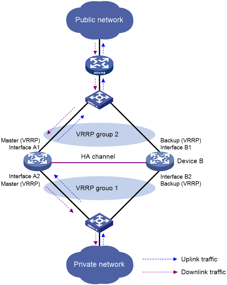
As shown in Figure 18, when Interface A2 of Device A fails, Device B becomes the master device in the VRRP group. Because Device B has NAT configuration information and service entries, NAT services are not interrupted after link switchover.
Figure 18 Traffic switchover in active/standby mode
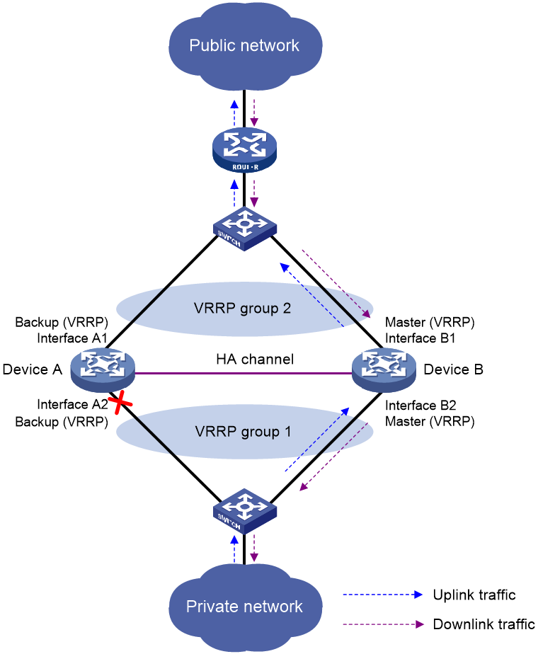
Configuring the active/standby mode
Restrictions and guidelines
Execute the vrrp vrid command in NAT address group view or port block group view on the primary device in the HA group.
Procedure
1. Enter system view.
system-view
2. Enter NAT address group view or NAT port block group view.
¡ Enter NAT address group view.
nat address-group group-id [ name group-name ]
¡ Enter NAT port block group view.
nat port-block-group group-id
3. Bind a VRRP group to the NAT address group or port block group.
vrrp vrid virtual-router-id
By default, a NAT address group or port block group is not bound to any VRRP group.
Configuring the dual-active mode
Restrictions and guidelines
Select one of the following methods for VRRP group binding according to the NAT resource allocation between the two devices in the HA group:
· If the two devices share the same NAT address group or port block group, execute the vrrp vrid command on the primary device. To prevent different master devices from using the same IP-port mapping for different hosts, specify the PAT translation mode and execute the nat remote-backup port-alloc command on the primary device.
· If the two devices use different NAT address groups or port block groups, user traffic with different source IP addresses is identified by ACLs in NAT rules. To enable different master devices to translate the forward user traffic, specify different gateway addresses for different internal users. To direct the reverse traffic to different master devices, bind NAT address groups or port block groups to different VRRP groups on the primary device.
Procedure
1. Enter system view.
system-view
2. Enter NAT address group view or NAT port block group view.
¡ Enter NAT address group view.
nat address-group group-id [ name group-name ]
¡ Enter NAT port block group view.
nat port-block-group group-id
3. Bind a VRRP group to the NAT address group or port block group.
vrrp vrid virtual-router-id
By default, a NAT address group or port block group is not bound to any VRRP group.
If you execute this command multiple times, the most recent configuration takes effect.
4. (Optional.) Specify NAT port block ranges for the two devices in the HA group.
a. Return to system view.
quit
b. Specify NAT port ranges for the two devices in the HA group.
nat remote-backup port-alloc { primary | secondary }
By default, the two devices in the HA group share NAT port resources.
The following table describes port ranges indicated by the keywords:
|
Keyword |
Port ranges |
|
primary |
If you do not configure a port range for public addresses, the available port range includes 1 to 255, 512 to 769, 1024 to 3513, and 6000 to 35769. If a port range is configured by executing the port-range command, the first half of the configured port range is available. |
|
secondary |
If you do not configure a port range for IP public addresses, the available port range includes 256 to 511, 770 to 1023, 3514 to 5999, and 35770 to 65535. If a port range is configured by executing the port-range command, the second half of the configured port range is available. |
Configuring NAT maintenance
Configuring periodic NAT statistics collection
About this task
This feature periodically counts sessions and port block assignment failures for address groups.
Restrictions and guidelines
This feature might cause intensive CPU usage. You can disable the feature when CPU resources are insufficient.
Procedure
1. Enter system view.
system-view
2. Enable periodic NAT statistics collection.
nat periodic-statistics enable
By default, periodic NAT statistics collection is disabled.
3. Configure the interval for periodic NAT statistics collection.
nat periodic-statistics interval interval
By default, the interval for periodic NAT statistics collection is 300 seconds.
A narrower interval indicates intensive CPU usage. As a best practice, use the default interval value.
Enabling statistics collection for NAT session creation rate
About this task
This feature collects information about NAT session creation rates. To view the statistics, use the display nat statistics command.
Procedure
1. Enter system view.
system-view
2. Enable statistics collection for NAT session creation rate.
nat session create-rate enable
By default, statistics collection for NAT session creation rate is disabled.
Specifying a probe method for detecting reachability of NAT address group members
About this task
The NAT address group probing uses an NQA template to detect the reachability of the addresses in the group. For information about NQA, see Network Management and Monitoring Configuration Guide.
The device periodically sends probe packets to the specified destination address in the NQA template. The source IP addresses in the probe packets are the IP addresses in the NAT address group.
· If the device receives a response packet for a probe, the probed source IP address can be used for address translation.
· If the device does not receive a response packet for a probe, the probed source IP address will be excluded from address translation temporarily. However, in the next NQA operation period, this excluded IP address is also probed. If a response is received in this round, the IP address can be used for address translation.
Restrictions and guidelines
You can specify multiple NQA templates in one NAT address group view. An IP address in the address group is identified as reachable as long as one probe for this IP address succeeds.
This feature is applicable to NAT address groups used for outbound address translation. The manually configured excluded IP addresses are not probed.
Make sure the NQA template used for NAT address group probing does not have source IP address configured.
Procedure
1. Enter system view.
system-view
2. Enter NAT address group view.
nat address-group group-id [ name group-name ]
3. Specify a probe method for the NAT address group.
probe template-name
By default, no probe method is specified for a NAT address group.
You can specify a nonexistent probe method. The probing takes effect only after you create and configure the NQA template.
Enabling sending ICMP error messages for NAT failures
About this task
By default, the device does not send ICMP error messages when NAT fails. Disabling sending ICMP error messages for NAT failures reduces useless packets, saves bandwidth, and avoids exposing the firewall IP address to the public network.
Restrictions and guidelines
Enable this feature for traceroute because the traceroute function requires ICMP error packets.
Procedure
1. Enter system view.
system-view
2. Enable sending ICMP error messages for NAT failures.
nat icmp-error reply
By default, no ICMP error messages are sent for NAT failures.
Configuring NAT logging
Configuring NAT session logging
About this task
NAT session logging records NAT session information, including translation information and access information.
A NAT device generates NAT session logs for the following events:
· NAT session establishment.
· NAT session removal. This event occurs when you add a configuration with a higher priority, remove a configuration, change ACLs, when a NAT session ages out, or when you manually delete a NAT session.
· Active NAT session logging. Active NAT flows refer to NAT sessions that exist within a period of time. When the specified interval for logging active NAT flows expires, the device records the existing NAT session information and generates a log. Logging for active NAT flows only supports flow log output to log hosts. For more information, see flow log configuration in Network Management and Monitoring Configuration Guide.
Procedure
1. Enter system view.
system-view
2. Enable NAT logging.
nat log enable [ acl { ipv4-acl-number | name ipv4-acl-name } ]
By default, NAT logging is disabled.
3. Enable NAT session logging.
¡ For NAT session establishment events:
nat log flow-begin
¡ For NAT session removal events:
nat log flow-end
¡ For active NAT flows:
nat log flow-active minutes
By default, NAT session logging is disabled.
Configuring NAT444 user logging
About this task
NAT444 user logs are used for user tracing. The NAT444 gateway generates a user log whenever it assigns or withdraws a port block. The log includes the private IP address, public IP address, and port block. You can use the public IP address and port numbers to locate the user's private IP address from the user logs.
A NAT444 gateway generates NAT user logs when one of the following events occurs:
· A port block is assigned.
For the NAT444 static port block mapping, the NAT444 gateway generates a user log when it translates the first connection from a private IP address.
For the NAT444 dynamic port block mapping, the NAT444 gateway generates a user log when it assigns or extends a port block for a private IP address.
· A port block is withdrawn.
For the NAT444 static port block mapping, the NAT444 gateway generates a user log when all connections from a private IP address are disconnected.
For the NAT444 dynamic port block mapping, the NAT444 gateway generates a user log when all the following conditions are met:
¡ All connections from a private IP address are disconnected.
¡ The port blocks (including the extended ones) assigned to the private IP address are withdrawn.
¡ The corresponding mapping entry is deleted.
Prerequisites
Before configuring NAT444 user logging, you must configure the custom NAT444 log generation and outputting features. For more information, see the information center in Network Management and Monitoring Configuration Guide.
Procedure
1. Enter system view.
system-view
2. Enable NAT logging.
nat log enable [ acl { ipv4-acl-number | name ipv4-acl-name } ]
By default, NAT logging is disabled.
The acl keyword does not take effect on NAT444 user logging.
3. Enable NAT444 user logging. Choose the options to configure as needed:
¡ For port block assignment:
nat log port-block-assign
¡ For port block withdrawal:
nat log port-block-withdraw
By default, NAT444 user logging is disabled.
Configuring NAT alarm logging
About this task
Packets that need to be translated are dropped if the NAT resources are not enough. In NO-PAT, the NAT resources refer to the public IP addresses. In EIM PAT, the NAT resources refer to public IP addresses and ports. In NAT444, the NAT resources refer to public IP addresses, port blocks, or ports in port blocks. NAT alarm logging monitors the usage of NAT resources and outputs logs if the NAT resources are not enough.
For NAT444 dynamic port block mappings, an alarm log is generated upon the port block assignment failure or the failure that port resources cannot meet the user address translation requirement.
Restrictions and guidelines
The nat log alarm command take effect only after you use the nat log enable command to enable NAT logging.
Prerequisites
Before configuring NAT alarm logging, you must configure the custom NAT log generation and outputting features. For more information, see the information center in Network Management and Monitoring Configuration Guide.
Procedure
1. Enter system view.
system-view
2. Enable NAT logging.
nat log enable [ acl { ipv4-acl-number | name ipv4-acl-name } ]
By default, NAT logging is disabled.
The acl keyword does not take effect on NAT alarm logging.
3. Enable NAT alarm logging.
nat log alarm
By default, NAT alarm logging is disabled.
An NAT alarm log is output when NAT resources run out.
4. (Optional.) Set the NAT444 port block usage threshold.
nat log port-block usage threshold threshold-value
By default, the NAT444 port block usage threshold is 90%.
The system generates alarm logs if the port block usage exceeds the threshold.
Enabling logging for IP usage of a NAT address group in NO-PAT mode
About this task
The system generates a log if the IP usage of a NAT address group exceeds the threshold.
Restrictions and guidelines
This feature takes effect only after you enable NAT logging by using the nat log enable command.
Procedure
1. Enter system view.
system-view
2. Enable NAT logging.
nat log enable [ acl { ipv4-acl-number | name ipv4-acl-name } ]
By default, NAT logging is disabled.
The acl keyword does not take effect on the logging for IP usage of a NAT address group in NO-PAT mode.
3. Enable logging for the IP usage of a NAT address group in NO-PAT mode and set a threshold.
nat log no-pat ip-usage [ threshold value ]
By default, logging is disabled for the IP usage of a NAT address group.
Configuring NAT in specific networks
Enabling NAT reply redirection
About this task
In some network scenarios, the inbound dynamic NAT is configured with tunneling, and multiple tunnel interfaces use the same NAT address group. In this case, the device will translate the source IP addresses of packets from different tunnels into the same NAT address before forwarding them. When the forwarding interface receives the reply packets, the device, by default, will not look up the NAT session table. This will cause the incorrect forwarding of the reply packets. To solve the problem, you can enable the NAT reply redirection feature on the forwarding interface. NAT reply redirection allows the interface to use the NAT session table to translate the destination IP addresses for NAT reply packets and find the correct output interfaces for those NATed reply packets.
Procedure
1. Enter system view.
system-view
2. Enter interface view.
interface interface-type interface-number
3. Enable NAT reply redirection.
nat redirect reply-route enable
By default, NAT reply redirection is disabled.
Enabling the deletion of timestamps in TCP SYN and SYN ACK packets
About this task
With this feature configured, the system deletes the timestamps from the TCP SYN and SYN ACK packets after dynamic address translation.
If PAT mode is configured on an interface by using nat inbound or nat outbound, and the tcp_timestams and tcp_tw_recycle function is configured on the TCP server, TCP connections might not be established. To solve the problem, you can shut down the tcp_tw_recycle function or configure the nat timestamp delete command.
Procedure
1. Enter system view.
system-view
2. Enable the deletion of timestamps in TCP SYN and SYN ACK packets
nat timestamp delete [ vpn-instance vpn-instance-name ]
By default, the deletion of timestamps in TCP SYN and SYN ACK packets is disabled.
You can enable this feature for multiple VPN instances by repeating the command with different VPN parameters.
Enabling NAT session recreation after link switchover
About this task
This feature is applicable to a WAN network where two interfaces of the NAT device are configured with outbound dynamic NAT rules using different address groups. When the link of one interface fails, traffic on this link is switched to the link of another interface and the NAT device operates as follows:
· If the two interfaces are in different security zones, the NAT device deletes old session entries after link switchover. When user traffic later arrives, it triggers the NAT session recreation. This mechanism ensures that internal users can access the external network.
· If the two interfaces are in the same security zone, the NAT device retains old session entries after link switchover. Internal users cannot access the external network because the device uses old session entries to match the user traffic. To avoid this issue, enable this feature to ensure availability of NAT services.
Procedure
1. Enter system view.
system-view
2. Enable NAT session recreation after link switchover.
nat link-switch recreate-session
By default, NAT session recreation is disabled after link switchover.
Display and maintenance commands for NAT
Execute display commands in any view and reset commands in user view.
|
Task |
Command |
|
Display the NAT ALG status for all supported protocols |
display nat alg |
|
Display all NAT configuration information. |
display nat all |
|
Display NAT address group information. |
display nat address-group [ group-id ] |
|
Display NAT DNS mapping configuration. |
display nat dns-map |
|
Display port ranges used by failover groups to implement Easy IP. |
display nat easy-ip failover-group port-range |
|
Display information about NAT EIM entries. |
In standalone mode: display nat eim [ slot slot-number [ cpu cpu-number ] ] In IRF mode: display nat eim [ chassis chassis-number slot slot-number [ cpu cpu-number ] ] |
|
Display inbound dynamic NAT configuration. |
display nat inbound |
|
Display NAT logging configuration. |
display nat log |
|
Display information about NAT NO-PAT entries. |
In standalone mode: display nat no-pat [ slot slot-number [ cpu cpu-number ] ] In IRF mode: display nat no-pat [ chassis chassis-number slot slot-number [ cpu cpu-number ] ] |
|
Display IP usage of NAT address groups in NO-PAT mode. |
In standalone mode: display nat no-pat ip-usage [ address-group { group-id | name group-name } ] [ slot slot-number [ cpu cpu-number ] ] In IRF mode: display nat no-pat ip-usage [ address-group { group-id | name group-name } ] [ chassis chassis-number slot slot-number [ cpu cpu-number ] ] |
|
Display outbound dynamic NAT configuration. |
display nat outbound |
|
display periodic NAT statistics |
In standalone mode: display nat periodic-statistics { address-group [ group-id | name group-name ] | ip global-ip } [ slot slot-number [ cpu cpu-number ] ] In IRF mode: display nat periodic-statistics { address-group [ group-id | name group-name ] | ip global-ip } [ chassis chassis-number slot slot-number [ cpu cpu-number ] ] |
|
Display the interface-based NAT policy configuration. |
display nat policy |
|
Display NAT server mappings. |
display nat server |
|
Display internal server group configuration. |
display nat server-group [ group-id ] |
|
Display NAT sessions. |
In standalone mode: display nat session [ [ responder ] { source-ip source-ip | destination-ip destination-ip } * [ vpn-instance vpn -instance-name ] ] [ slot slot-number [ cpu cpu-number ] ] [ verbose ] In IRF mode: display nat session [ [ responder ] { source-ip source-ip | destination-ip destination-ip } * [ vpn-instance vpn -instance-name ] ] [ chassis chassis-number slot slot-number [ cpu cpu-number ] ] [ verbose ] |
|
Display static NAT mappings. |
display nat static |
|
Display NAT statistics. |
In standalone mode: display nat statistics [ summary ] [ slot slot-number [ cpu cpu-number ] ] In IRF mode: display nat statistics [ summary ] [ chassis chassis-number slot slot-number [ cpu cpu-number ] ] |
|
Display static outbound port block mapping rules for NAT444 |
display nat outbound port-block-group |
|
Display NAT port block group configuration. |
display nat port-block-group [ group-id ] |
|
Display NAT port block mappings. |
In standalone mode: display nat port-block { dynamic [ address-group { group-id | name group-name } ] [ ds-lite-b4 ] | static [ port-block-group group-id ] } [ slot slot-number [ cpu cpu-number ] ] In IRF mode: display nat port-block { dynamic [ address-group { group-id | name group-name } ] [ ds-lite-b4 ] | static [ port-block-group group-id ] } [ chassis chassis-number slot slot-number [ cpu cpu-number ] ] |
|
In standalone mode: display nat port-block-usage [ address-group group-id ] [ slot slot-number [ cpu cpu-number ] ] In IRF mode: display nat port-block-usage [ address-group group-id ] [ chassis chassis-number slot slot-number [ cpu cpu-number ] ] |
|
|
Display NAT address group probe information. |
display nat probe address-group [ group-id ] |
|
Clear NAT counting statistics. |
reset nat count statistics { all | dynamic | global-policy | server | static | static-port-block } |
|
Clear periodic NAT statistics |
In standalone mode: reset nat periodic-statistics [ slot slot-number [ cpu cpu-number ] ] In IRF mode: reset nat periodic-statistics [ chassis chassis-number slot slot-number [ cpu cpu-number ] ] |
|
Clear NAT sessions. |
In standalone mode: reset nat session [ slot slot-number [ cpu cpu-number ] ] In IRF mode: reset nat session [ chassis chassis-number slot slot-number [ cpu cpu-number ] ] |
NAT configuration examples
Example: Configuring outbound one-to-one static NAT
Network configuration
Configure static NAT to allow the host at 10.110.10.8/24 to access the server at 201.20.1.1/24 on the Internet.
Figure 19 Network diagram

Procedure
1. Assign IP addresses to interfaces:
# Assign an IP address to interface GigabitEthernet 1/0/1.
<Device> system-view
[Device] interface gigabitethernet 1/0/1
[Device-GigabitEthernet1/0/1] ip address 10.110.10.1 24
[Device-GigabitEthernet1/0/1] quit
# Assign IP addresses to other interfaces in the same way. (Details not shown.)
2. Add interfaces to security zones.
[Device] security-zone name trust
[Device-security-zone-Trust] import interface gigabitethernet 1/0/1
[Device-security-zone-Trust] quit
[Device] security-zone name untrust
[Device-security-zone-Untrust] import interface gigabitethernet 1/0/2
[Device-security-zone-Untrust] quit
3. Configure settings for routing.
This example configures a static route, and the next hop in the routes is 202.38.1.2.
[Device] ip route-static 201.20.1.0 24 202.38.1.2
4. Configure a security policy:
# Configure a rule named trust-untrust to permit the packets from the host to the server.
[Device] security-policy ip
[Device-security-policy-ip] rule name trust-untrust
[Device-security-policy-ip-1-trust-untrust] source-zone trust
[Device-security-policy-ip-1-trust-untrust] destination-zone untrust
[Device-security-policy-ip-1-trust-untrust] source-ip-host 10.110.10.8
[Device-security-policy-ip-1-trust-untrust] destination-ip-host 201.20.1.1
[Device-security-policy-ip-1-trust-untrust] action pass
[Device-security-policy-ip-1-trust-untrust] quit
[Device-security-policy-ip] quit
5. Configure NAT:
# Configure a one-to-one static NAT mapping between the private address 10.110.10.8 and the public address 202.38.1.100.
[Device] nat static outbound 10.110.10.8 202.38.1.100
[Device] interface gigabitethernet 1/0/2
[Device-GigabitEthernet1/0/2] nat static enable
[Device-GigabitEthernet1/0/2] quit
Verifying the configuration
# Verify that the host at 10.110.10.8/24 can access the server on the Internet. (Details not shown.)
# Display static NAT configuration.
[Device] display nat static
Static NAT mappings:
Totally 1 outbound static NAT mappings.
IP-to-IP:
Local IP : 10.110.10.8
Global IP : 202.38.1.100
Config status: Active
Interfaces enabled with static NAT:
Totally 1 interfaces enabled with static NAT.
Interface: GigabitEthernet1/0/2
NAT counting : 0
Config status: Active
Global flow-table status: Active
Local flow-table status: Active
# Display NAT sessions.
[Device] display nat session verbose
Slot 1:
Initiator:
Source IP/port: 10.110.10.8/54765
Destination IP/port: 202.38.1.2/23
DS-Lite tunnel peer: -
VPN instance/VLAN ID/Inline ID: -/-/-
Protocol: TCP(6)
Inbound interface: GigabitEthernet1/0/1
Source security zone: Trust
Responder:
Source IP/port: 202.38.1.2/23
Destination IP/port: 202.38.1.100/54765
DS-Lite tunnel peer: -
VPN instance/VLAN ID/Inline ID: -/-/-
Protocol: TCP(6)
Inbound interface: GigabitEthernet1/0/2
Source security zone: Untrust
State: TCP_ESTABLISHED
Application: TELNET
Rule ID: -/-/-
Rule name:
Start time: 2017-05-19 10:57:47 TTL: 1195s
Initiator->Responder: 8 packets 375 bytes
Responder->Initiator: 10 packets 851 bytes
Total sessions found: 1
Example: Configuring outbound dynamic NAT (non-overlapping addresses)
Network configuration
As shown in Figure 20, a company has a private address 192.168.0.0/16 and two public IP addresses 202.38.1.2 and 202.38.1.3. Configure outbound dynamic NAT to allow only internal users on subnet 192.168.1.0/24 to access the Internet.

Procedure
1. Assign IP addresses to interfaces:
# Assign an IP address to interface GigabitEthernet 1/0/1.
<Device> system-view
[Device] interface gigabitethernet 1/0/1
[Device-GigabitEthernet1/0/1] ip address 192.168.1.1 16
[Device-GigabitEthernet1/0/1] quit
# Assign IP addresses to other interfaces in the same way. (Details not shown.)
2. Add interfaces to security zones.
[Device] security-zone name trust
[Device-security-zone-Trust] import interface gigabitethernet 1/0/1
[Device-security-zone-Trust] quit
[Device] security-zone name untrust
[Device-security-zone-Untrust] import interface gigabitethernet 1/0/2
[Device-security-zone-Untrust] quit
3. Configure settings for routing.
This example configures a static route, and the next hop in the routes is 202.38.1.4.
[Device] ip route-static 200.1.1.0 24 202.38.1.4
4. Configure a security policy:
# Configure a rule named trust-untrust to permit the packets from the hosts to the server.
[Device] security-policy ip
[Device-security-policy-ip] rule name trust-untrust
[Device-security-policy-ip-1-trust-untrust] source-zone trust
[Device-security-policy-ip-1-trust-untrust] destination-zone untrust
[Device-security-policy-ip-1-trust-untrust] source-ip-subnet 192.168.1.0 24
[Device-security-policy-ip-1-trust-untrust] destination-ip-host 200.1.1.10
[Device-security-policy-ip-1-trust-untrust] action pass
[Device-security-policy-ip-1-trust-untrust] quit
[Device-security-policy-ip] quit
5. Configure NAT:
# Configure address group 0, and add an address range from 202.38.1.2 to 202.38.1.3 to the group.
[Device] nat address-group 0
[Device-address-group-0] address 202.38.1.2 202.38.1.3
[Device-address-group-0] quit
# Configure ACL 2000 to identify packets from subnet 192.168.1.0/24.
[Device] acl basic 2000
[Device-acl-ipv4-basic-2000] rule permit source 192.168.1.0 0.0.0.255
[Device-acl-ipv4-basic-2000] quit
# Enable outbound dynamic PAT on GigabitEthernet 1/0/2. The source IP addresses of the packets permitted by the ACL rule is translated into the addresses in address group 0.
[Device] interface gigabitethernet 1/0/2
[Device-GigabitEthernet1/0/2] nat outbound 2000 address-group 0
Verifying the configuration
# Verify that Host A can access the WWW server, while Host B cannot. (Details not shown.)
# Display all NAT configuration and statistics.
[Device] display nat all
NAT address group information:
Totally 1 NAT address groups.
Address group ID: 0
Port range: 1-65535
Blade-load-sharing-group: Blade4fw-m90001
Address information:
Start address End address
202.38.1.2 202.38.1.3
NAT outbound information:
Totally 1 NAT outbound rules.
Interface: GigabitEthernet1/0/2
ACL: 2000
Address group ID: 0
Port-preserved: N NO-PAT: N Reversible: N
Config status: Active
NAT logging:
Log enable : Disabled
Flow-begin : Disabled
Flow-end : Disabled
Flow-active : Disabled
Port-block-assign : Disabled
Port-block-withdraw : Disabled
Alarm : Disabled
NO-PAT IP usage : Disabled
NAT mapping behavior:
Mapping mode : Address and Port-Dependent
ACL : ---
Config status: Active
NAT ALG:
DNS : Enabled
FTP : Enabled
H323 : Disabled
ICMP-ERROR : Enabled
ILS : Disabled
MGCP : Disabled
NBT : Disabled
PPTP : Enabled
RTSP : Enabled
RSH : Disabled
SCCP : Disabled
SIP : Disabled
SQLNET : Disabled
TFTP : Disabled
XDMCP : Disabled
Static NAT load balancing: Disabled
# Display NAT sessions that are generated when Host A accesses the WWW server.
[Device] display nat session verbose
Slot 1:
Initiator:
Source IP/port: 192.168.1.10/52082
Destination IP/port: 200.1.1.10/80
DS-Lite tunnel peer: -
VPN instance/VLAN ID/Inline ID: -/-/-
Protocol: TCP(6)
Inbound interface: GigabitEthernet1/0/1
Source security zone: Trust
Responder:
Source IP/port: 200.1.1.10/80
Destination IP/port: 202.38.1.2/1036
DS-Lite tunnel peer: -
VPN instance/VLAN ID/Inline ID: -/-/-
Protocol: TCP(6)
Inbound interface: GigabitEthernet1/0/2
Source security zone: Untrust
State: TCP_ESTABLISHED
Application: HTTP
Rule ID: -/-/-
Rule name:
Start time: 2017-05-19 16:16:59 TTL: 9995s
Initiator->Responder: 551 packets 32547 bytes
Responder->Initiator: 956 packets 1385514 bytes
Total sessions found: 1
Example: Configuring outbound bidirectional NAT
Network configuration
As shown in Figure 21, the private network where the Web server resides overlaps with the company private network 192.168.1.0/24. The company has two public IP addresses 202.38.1.2 and 202.38.1.3. Configure NAT to allow internal users to access the external Web server by using the server's domain name.
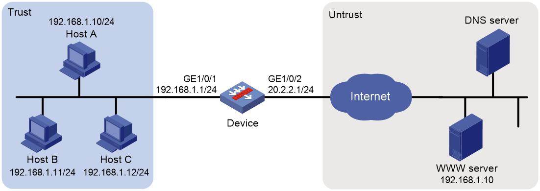
Requirements analysis
To meet the network requirements, you must perform the following tasks:
· Configure inbound dynamic NAT ALG to make sure the internal host reaches the Web server instead of another internal host. NAT ALG can translate the Web server's IP address in the DNS reply payload to a dynamically assigned public address.
· Configure outbound dynamic NAT to translate the source IP address of packets from an internal host to a dynamically assigned public address.
· Add a static route to the public IP address of the external Web server.
Procedure
1. Assign IP addresses to interfaces:
# Assign an IP address to interface GigabitEthernet 1/0/1.
<Device> system-view
[Device] interface gigabitethernet 1/0/1
[Device-GigabitEthernet1/0/1] ip address 192.168.1.1 24
[Device-GigabitEthernet1/0/1] quit
# Assign IP addresses to other interfaces in the same way. (Details not shown.)
2. Add interfaces to security zones.
[Device] security-zone name trust
[Device-security-zone-Trust] import interface gigabitethernet 1/0/1
[Device-security-zone-Trust] quit
[Device] security-zone name untrust
[Device-security-zone-Untrust] import interface gigabitethernet 1/0/2
[Device-security-zone-Untrust] quit
3. Configure settings for routing.
This example configures a static route, and the next hop in the routes is 20.2.2.2.
[Device] ip route-static 202.38.1.2 32 20.2.2.2
4. Configure a security policy:
# Configure a rule named trust-untrust to permit the packets from the hosts to the servers.
[Device] security-policy ip
[Device-security-policy-ip] rule name trust-untrust
[Device-security-policy-ip-1-trust-untrust] source-zone trust
[Device-security-policy-ip-1-trust-untrust] destination-zone untrust
[Device-security-policy-ip-1-trust-untrust] source-ip-subnet 192.168.1.0 24
[Device-security-policy-ip-1-trust-untrust] destination-ip-host 202.38.1.2
[Device-security-policy-ip-1-trust-untrust] action pass
[Device-security-policy-ip-1-trust-untrust] quit
[Device-security-policy-ip] quit
5. Configure NAT:
# Enable NAT ALG for DNS.
[Device] nat alg dns
# Configure ACL 2000 to identify packets from subnet 192.168.1.0/24.
[Device] acl basic 2000
[Device-acl-ipv4-basic-2000] rule permit source 192.168.1.0 0.0.0.255
[Device-acl-ipv4-basic-2000] quit
# Create address groups.
[Device] nat address-group 1
[Device-address-group-1] address 202.38.1.2 202.38.1.2
[Device-address-group-1] quit
[Device] nat address-group 2
[Device-address-group-2] address 202.38.1.3 202.38.1.3
[Device-address-group-2] quit
# Enable inbound NO-PAT on GigabitEthernet 1/0/2 to translate the source IP address in the DNS reply payload into the address in address group 1, and allow reversible NAT.
[Device] interface gigabitethernet 1/0/2
[Device-GigabitEthernet1/0/2] nat inbound 2000 address-group 1 no-pat reversible
# Enable outbound PAT on GigabitEthernet 1/0/2 to translate the source address of outgoing packets into the address in address group 2.
[Device-GigabitEthernet1/0/2] nat outbound 2000 address-group 2
[Device-GigabitEthernet1/0/2] quit
Verifying the configuration
# Verify that Host A can access the Web server by using its domain name. (Details not shown.)
# Display all NAT configuration and statistics.
[Device] display nat all
NAT address group information:
Totally 2 NAT address groups.
Address group ID: 1
Port range: 1-65535
Blade-load-sharing-group: Blade4fw-m90001
Address information:
Start address End address
202.38.1.2 202.38.1.2
Address group ID: 2
Port range: 1-65535
Blade-load-sharing-group: Blade4fw-m90001
Address information:
Start address End address
202.38.1.3 202.38.1.3
NAT inbound information:
Totally 1 NAT inbound rules.
Interface: GigabitEthernet1/0/2
ACL: 2000
Address group ID: 1
Add route: N NO-PAT: Y Reversible: Y
Config status: Active
NAT outbound information:
Totally 1 NAT outbound rules.
Interface: GigabitEthernet1/0/2
ACL: 2000
Address group ID: 2
Port-preserved: N NO-PAT: N Reversible: N
Config status: Active
NAT logging:
Log enable : Disabled
Flow-begin : Disabled
Flow-end : Disabled
Flow-active : Disabled
Port-block-assign : Disabled
Port-block-withdraw : Disabled
Alarm : Disabled
NO-PAT IP usage : Disabled
NAT mapping behavior:
Mapping mode : Address and Port-Dependent
ACL : ---
Config status: Active
NAT ALG:
DNS : Enabled
FTP : Enabled
H323 : Disabled
ICMP-ERROR : Enabled
ILS : Disabled
MGCP : Disabled
NBT : Disabled
PPTP : Enabled
RTSP : Enabled
RSH : Disabled
SCCP : Disabled
SIP : Disabled
SQLNET : Disabled
TFTP : Disabled
XDMCP : Disabled
Static NAT load balancing: Disabled
# Display NAT sessions that are generated when Host A accesses the Web server.
[Device] display nat session verbose
Slot 1:
Initiator:
Source IP/port: 192.168.1.10/51716
Destination IP/port: 202.38.1.2/80
DS-Lite tunnel peer: -
VPN instance/VLAN ID/Inline ID: -/-/-
Protocol: TCP(6)
Inbound interface: GigabitEthernet1/0/1
Source security zone: Trust
Responder:
Source IP/port: 202.38.1.2/80
Destination IP/port: 202.38.1.3/1059
DS-Lite tunnel peer: -
VPN instance/VLAN ID/Inline ID: -/-/-
Protocol: TCP(6)
Inbound interface: GigabitEthernet1/0/2
Source security zone: Untrust
State: TCP_ESTABLISHED
Application: HTTP
Rule ID: -/-/-
Rule name:
Start time: 2017-05-21 15:36:29 TTL: 1197s
Initiator->Responder: 125 packets 6304 bytes
Responder->Initiator: 223 packets 325718 bytes
Total sessions found: 1
Example: Configuring NAT Server for external-to-internal access
Network configuration
As shown in Figure 22, two Web servers, one FTP server and one SMTP server, are in the internal network to provide services for external users. The internal network address is 10.110.0.0/16. The company has three public IP addresses from 202.38.1.1/24 to 202.38.1.3/24.
Configure the NAT Server feature to allow the external user to access the internal servers with public address 202.38.1.1/24.

Procedure
1. Assign IP addresses to interfaces:
# Assign an IP address to interface GigabitEthernet 1/0/1.
<Device> system-view
[Device] interface gigabitethernet 1/0/1
[Device-GigabitEthernet1/0/1] ip address 10.110.10.10 16
[Device-GigabitEthernet1/0/1] quit
# Assign IP addresses to other interfaces in the same way. (Details not shown.)
2. Add interfaces to security zones.
[Device] security-zone name trust
[Device-security-zone-Trust] import interface gigabitethernet 1/0/1
[Device-security-zone-Trust] quit
[Device] security-zone name untrust
[Device-security-zone-Untrust] import interface gigabitethernet 1/0/2
[Device-security-zone-Untrust] quit
3. Configure a security policy:
# Configure a rule named untrust-trust to permit the packets from the host to the servers.
[Device] security-policy ip
[Device-security-policy-ip] rule name untrust-trust
[Device-security-policy-ip-1-untrust-trust] source-zone untrust
[Device-security-policy-ip-1-untrust-trust] destination-zone trust
[Device-security-policy-ip-1-untrust-trust] destination-ip-host 10.110.10.1
[Device-security-policy-ip-1-untrust-trust] destination-ip-host 10.110.10.2
[Device-security-policy-ip-1-untrust-trust] destination-ip-host 10.110.10.3
[Device-security-policy-ip-1-untrust-trust] destination-ip-host 10.110.10.4
[Device-security-policy-ip-1-untrust-trust] action pass
[Device-security-policy-ip-1-untrust-trust] quit
[Device-security-policy-ip] quit
4. Configure NAT:
# Configure a NAT server mapping to allow external users to access the FTP server by using the address 202.38.1.1 and port 21.
[Device] interface gigabitethernet 1/0/2
[Device-GigabitEthernet1/0/2] nat server protocol tcp global 202.38.1.1 21 inside 10.110.10.3 ftp
# Configure a NAT server mapping to allow external users to access the Web server 1 by using the address 202.38.1.1 and port 80.
[Device-GigabitEthernet1/0/2] nat server protocol tcp global 202.38.1.1 80 inside 10.110.10.1 http
# Configure a NAT server mapping to allow external users to access the Web server 2 by using the address 202.38.1.1 and port 8080.
[Device-GigabitEthernet1/0/2] nat server protocol tcp global 202.38.1.1 8080 inside 10.110.10.2 http
# Configure a NAT server mapping to allow external users to access the SMTP server by using the address 202.38.1.1 and port number defined by SMTP.
[Device-GigabitEthernet1/0/2] nat server protocol tcp global 202.38.1.1 smtp inside 10.110.10.4 smtp
[Device-GigabitEthernet1/0/2] quit
Verifying the configuration
# Verify that the host on the external network can access the internal servers by using the public addresses. (Details not shown.)
# Display all NAT configuration and statistics.
[Device] display nat all
NAT internal server information:
Totally 4 internal servers.
Interface: GigabitEthernet1/0/2
Protocol: 6(TCP)
Global IP/port: 202.38.1.1/21
Local IP/port : 10.110.10.3/21
Rule name : ServerRule_1
NAT counting : 0
Config status : Active
Interface: GigabitEthernet1/0/2
Protocol: 6(TCP)
Global IP/port: 202.38.1.1/25
Local IP/port : 10.110.10.4/25
Rule name : ServerRule_4
NAT counting : 0
Config status : Active
Interface: GigabitEthernet1/0/2
Protocol: 6(TCP)
Global IP/port: 202.38.1.1/80
Local IP/port : 10.110.10.1/80
Rule name : ServerRule_2
NAT counting : 0
Config status : Active
Interface: GigabitEthernet1/0/2
Protocol: 6(TCP)
Global IP/port: 202.38.1.1/8080
Local IP/port : 10.110.10.2/80
Rule name : ServerRule_3
NAT counting : 0
Config status : Active
NAT logging:
Log enable : Disabled
Flow-begin : Disabled
Flow-end : Disabled
Flow-active : Disabled
Port-block-assign : Disabled
Port-block-withdraw : Disabled
Alarm : Disabled
NO-PAT IP usage : Disabled
NAT mapping behavior:
Mapping mode : Address and Port-Dependent
ACL : ---
Config status: Active
NAT ALG:
DNS : Enabled
FTP : Enabled
H323 : Disabled
ICMP-ERROR : Enabled
ILS : Disabled
MGCP : Disabled
NBT : Disabled
PPTP : Enabled
RTSP : Enabled
RSH : Disabled
SCCP : Disabled
SIP : Disabled
SQLNET : Disabled
TFTP : Disabled
XDMCP : Disabled
Static NAT load balancing: Disabled
# Display NAT sessions that are generated when Host accesses the FTP server.
[Device] display nat session verbose
Slot 1:
Initiator:
Source IP/port: 202.38.1.2/52802
Destination IP/port: 202.38.1.1/21
DS-Lite tunnel peer: -
VPN instance/VLAN ID/Inline ID: -/-/-
Protocol: TCP(6)
Inbound interface: GigabitEthernet1/0/2
Source security zone: Untrust
Responder:
Source IP/port: 10.110.10.3/21
Destination IP/port: 202.38.1.2/52802
DS-Lite tunnel peer: -
VPN instance/VLAN ID/Inline ID: -/-/-
Protocol: TCP(6)
Inbound interface: GigabitEthernet1/0/1
Source security zone: Trust
State: TCP_ESTABLISHED
Application: FTP
Rule ID: -/-/-
Rule name:
Start time: 2017-05-21 11:13:39 TTL: 3597s
Initiator->Responder: 7 packets 313 bytes
Responder->Initiator: 6 packets 330 bytes
Total sessions found: 1
Example: Configuring NAT Server for external-to-internal access through domain name
Network configuration
As shown in Figure 23, Web server at 10.110.10.2/24 in the internal network provides services for external users. A DNS server at 10.110.10.3/24 is used to resolve the domain name of the Web server. The company has two public IP addresses: 202.38.1.2 and 202.38.1.3.
Configure NAT Server to allow external users to access the internal Web server by using the domain name.
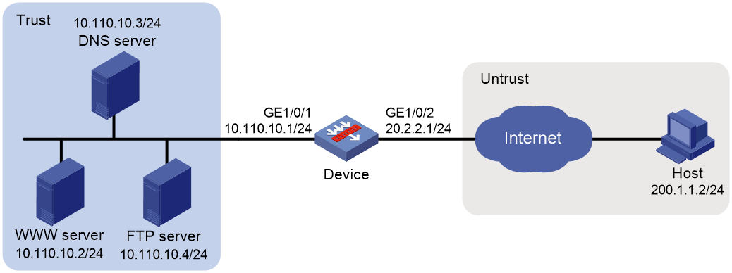
Requirements analysis
To meet the network requirements, you must perform the following tasks:
· Configure a NAT server mapping to map the private IP address and port of the DNS server to a public address and port. The mapping allows the external host to access the internal DNS server for domain name resolution.
· Enable ALG for DNS and configure outbound dynamic NAT to translate the private IP address of the Web server in the payload of the DNS response packet into a public IP address.
Procedure
1. Assign IP addresses to interfaces:
# Assign an IP address to interface GigabitEthernet 1/0/1.
<Device> system-view
[Device] interface gigabitethernet 1/0/1
[Device-GigabitEthernet1/0/1] ip address 10.110.10.1 24
[Device-GigabitEthernet1/0/1] quit
# Assign IP addresses to other interfaces in the same way. (Details not shown.)
2. Add interfaces to security zones.
[Device] security-zone name trust
[Device-security-zone-Trust] import interface gigabitethernet 1/0/1
[Device-security-zone-Trust] quit
[Device] security-zone name untrust
[Device-security-zone-Untrust] import interface gigabitethernet 1/0/2
[Device-security-zone-Untrust] quit
3. Configure a security policy:
# Configure a rule named untrust-trust to permit the packets from the host to the servers.
[Device] security-policy ip
[Device-security-policy-ip] rule name untrust-trust
[Device-security-policy-ip-1-untrust-trust] source-zone untrust
[Device-security-policy-ip-1-untrust-trust] destination-zone trust
[Device-security-policy-ip-1-untrust-trust] destination-ip-host 10.110.10.2
[Device-security-policy-ip-1-untrust-trust] destination-ip-host 10.110.10.3
[Device-security-policy-ip-1-untrust-trust] destination-ip-host 10.110.10.4
[Device-security-policy-ip-1-untrust-trust] action pass
[Device-security-policy-ip-1-untrust-trust] quit
[Device-security-policy-ip] quit
4. Configure NAT:
# Enable NAT with ALG for DNS.
[Device] nat alg dns
# Configure ACL 2000, and create a rule to permit packets only from 10.110.10.2 to pass through.
[Device] acl basic 2000
[Device-acl-ipv4-basic-2000] rule permit source 10.110.10.2 0
[Device-acl-ipv4-basic-2000] quit
# Create an address group.
[Device] nat address-group 1
[Device-address-group-1] address 202.38.1.3 202.38.1.3
[Device-address-group-1] quit
# Configure a NAT server mapping on GigabitEthernet 1/0/2 to map the address 202.38.1.1 to 10.110.10.3. External users can access the internal DNS server.
[Device] interface gigabitethernet 1/0/2
[Device-GigabitEthernet1/0/2] nat server protocol udp global 202.38.1.2 inside 10.110.10.3 dns
# Enable outbound NO-PAT on GigabitEthernet 1/0/2. Use the address in address group 1 to translate the private address in DNS response payload, and allow reversible NAT.
[Device-GigabitEthernet1/0/2] nat outbound 2000 address-group 1 no-pat reversible
[Device-GigabitEthernet1/0/2] quit
Verifying the configuration
# Verify that the host on the external network can access the internal Web server by using the server's domain name. (Details not shown.)
# Display all NAT configuration and statistics.
[Device] display nat all
NAT address group information:
Totally 1 NAT address groups.
Address group ID: 1
Port range: 1-65535
Blade-load-sharing-group: Blade4fw-m90001
Address information:
Start address End address
202.38.1.3 202.38.1.3
NAT outbound information:
Totally 1 NAT outbound rules.
Interface: GigabitEthernet1/0/2
ACL: 2000
Address group ID: 1
Port-preserved: N NO-PAT: Y Reversible: Y
Config status: Active
NAT internal server information:
Totally 1 internal servers.
Interface: GigabitEthernet1/0/2
Protocol: 17(UDP)
Global IP/port: 202.38.1.2/53
Local IP/port : 10.110.10.3/53
Rule name : ServerRule_1
NAT counting : 0
Config status : Active
NAT logging:
Log enable : Disabled
Flow-begin : Disabled
Flow-end : Disabled
Flow-active : Disabled
Port-block-assign : Disabled
Port-block-withdraw : Disabled
Alarm : Disabled
NO-PAT IP usage : Disabled
NAT mapping behavior:
Mapping mode : Address and Port-Dependent
ACL : ---
Config status: Active
NAT ALG:
DNS : Enabled
FTP : Enabled
H323 : Disabled
ICMP-ERROR : Enabled
ILS : Disabled
MGCP : Disabled
NBT : Disabled
PPTP : Enabled
RTSP : Enabled
RSH : Disabled
SCCP : Disabled
SIP : Disabled
SQLNET : Disabled
TFTP : Disabled
XDMCP : Disabled
Static NAT load balancing: Disabled
# Display NAT sessions that are generated when Host accesses Web server.
[Device] display nat session verbose
Slot 1:
Initiator:
Source IP/port: 200.1.1.2/1694
Destination IP/port: 202.38.1.3/8080
DS-Lite tunnel peer: -
VPN instance/VLAN ID/Inline ID: -/-/-
Protocol: TCP(6)
Inbound interface: GigabitEthernet1/0/2
Source security zone: Untrust
Responder:
Source IP/port: 10.110.10.2/8080
Destination IP/port: 200.1.1.2/1694
DS-Lite tunnel peer: -
VPN instance/VLAN ID/Inline ID: -/-/-
Protocol: TCP(6)
Inbound interface: GigabitEthernet1/0/1
Source security zone: Trust
State: TCP_ESTABLISHED
Application: HTTP
Rule ID: -/-/-
Rule name:
Start time: 2017-06-15 14:53:29 TTL: 3597s
Initiator->Responder: 7 packets 308 bytes
Responder->Initiator: 5 packets 312 bytes
Total sessions found: 1
Example: Configuring NAT Server for external-to-internal access through domain name
Network configuration
As shown in Figure 24, an intranet uses the subnet 192.168.1.0/24. The Web server at 192.168.1.2/24 provides Web services for external users and the DNS server at 192.168.1.3/24 resolves the domain name of the Web server. The company has 3 public addresses 202.38.1.2, 202.38.1.3, and 202.38.1.4.
Configure NAT to allow external host at 192.168.1.2 in the external network to use the domain name to access the internal Web server.
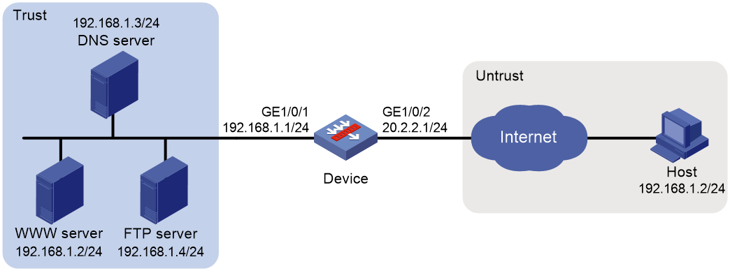
Requirements analysis
To meet the network requirements, you must perform the following tasks:
· Configure a NAT server mapping to map the private IP address and port of the DNS server to a public IP address and port. NAT Server allows the external host to access the internal DNS server for domain name resolution.
· Configure outbound dynamic NAT and enable NAT ALG for DNS. The Web server's IP address is the same as the external host's IP address. NAT ALG can translate the Web server's private address in the payload of the DNS response packet to a dynamically assigned public address.
· Configure inbound dynamic NAT. The external host's IP address is the same as the Web server's IP address. Inbound dynamic NAT can translate the external host's IP address into a dynamically assigned public address.
· Add a static route to the public IP address of the external host with GigabitEthernet 1/0/2 as the output interface.
Procedure
1. Assign IP addresses to interfaces:
# Assign an IP address to interface GigabitEthernet 1/0/1.
<Device> system-view
[Device] interface gigabitethernet 1/0/1
[Device-GigabitEthernet1/0/1] ip address 192.168.1.1 24
[Device-GigabitEthernet1/0/1] quit
# Assign IP addresses to other interfaces in the same way. (Details not shown.)
2. Add interfaces to security zones.
[Device] security-zone name trust
[Device-security-zone-Trust] import interface gigabitethernet 1/0/1
[Device-security-zone-Trust] quit
[Device] security-zone name untrust
[Device-security-zone-Untrust] import interface gigabitethernet 1/0/2
[Device-security-zone-Untrust] quit
3. Configure settings for routing.
This example configures a static route, and the next hop in the routes is 20.2.2.2.
[Device] ip route-static 202.38.1.3 32 20.2.2.2
4. Configure a security policy:
# Configure a rule named untrust-trust to permit the packets from the host to the servers.
[Device] security-policy ip
[Device-security-policy-ip] rule name untrust-trust
[Device-security-policy-ip-1-untrust-trust] source-zone untrust
[Device-security-policy-ip-1-untrust-trust] destination-zone trust
[Device-security-policy-ip-1-untrust-trust] destination-ip-host 192.168.1.2
[Device-security-policy-ip-1-untrust-trust] destination-ip-host 192.168.1.3
[Device-security-policy-ip-1-untrust-trust] destination-ip-host 192.168.1.4
[Device-security-policy-ip-1-untrust-trust] action pass
[Device-security-policy-ip-1-untrust-trust] quit
[Device-security-policy-ip] quit
5. Configure NAT:
# Enable NAT ALG for DNS.
[Device] nat alg dns
# Configure ACL 2000 to identify packets from subnet 192.168.1.0/24.
[Device] acl basic 2000
[Device-acl-ipv4-basic-2000] rule permit source 192.168.1.0 0.0.0.255
[Device-acl-ipv4-basic-2000] quit
# Create address groups.
[Device] nat address-group 1
[Device-address-group-1] address 202.38.1.2 202.38.1.2
[Device-address-group-1] quit
[Device] nat address-group 2
[Device-address-group-2] address 202.38.1.3 202.38.1.3
[Device-address-group-2] quit
# Configure a NAT server mapping on GigabitEthernet 1/0/2 to allow external hosts to access the internal DNS server by using the address 202.38.1.4.
[Device] interface gigabitethernet 1/0/2
[Device-GigabitEthernet1/0/2] nat server protocol udp global 202.38.1.4 inside 192.168.1.3 dns
# Enable outbound NO-PAT on GigabitEthernet 1/0/2 to translate IP address of the Web server in the DNS response payload into the address in address group 1, and allow reversible NAT.
[Device-GigabitEthernet1/0/2] nat outbound 2000 address-group 1 no-pat reversible
# Enable inbound PAT on interface GigabitEthernet 1/0/2 to translate the source address of packets going to the internal network to the address in address group 2.
[Device-GigabitEthernet1/0/2] nat inbound 2000 address-group 2
[Device-GigabitEthernet1/0/2] quit
Verifying the configuration
# Verify that the host on the external network can use the domain name to access the internal Web server whose address is the same as the host. (Details not shown.)
# Display all NAT configuration and statistics.
[Device] display nat all
NAT address group information:
Totally 2 NAT address groups.
Address group ID: 1
Port range: 1-65535
Blade-load-sharing-group: Blade4fw-m90001
Address information:
Start address End address
202.38.1.2 202.38.1.2
Address group ID: 2
Port range: 1-65535
Address information:
Start address End address
202.38.1.3 202.38.1.3
NAT inbound information:
Totally 1 NAT inbound rules.
Interface: GigabitEthernet1/0/2
ACL: 2000
Address group ID: 2
Add route: N NO-PAT: N Reversible: N
Config status: Active
NAT outbound information:
Totally 1 NAT outbound rules.
Interface: GigabitEthernet1/0/2
ACL: 2000
Address group ID: 1
Port-preserved: N NO-PAT: Y Reversible: Y
Config status: Active
NAT internal server information:
Totally 1 internal servers.
Interface: GigabitEthernet1/0/2
Protocol: 17(UDP)
Global IP/port: 202.38.1.4/53
Local IP/port : 200.1.1.3/53
Rule name : ServerRule_1
NAT counting : 0
Config status : Active
NAT logging:
Log enable : Disabled
Flow-begin : Disabled
Flow-end : Disabled
Flow-active : Disabled
Port-block-assign : Disabled
Port-block-withdraw : Disabled
Alarm : Disabled
NO-PAT IP usage : Disabled
NAT mapping behavior:
Mapping mode : Address and Port-Dependent
ACL : ---
Config status: Active
NAT ALG:
DNS : Enabled
FTP : Enabled
H323 : Disabled
ICMP-ERROR : Enabled
ILS : Disabled
MGCP : Disabled
NBT : Disabled
PPTP : Enabled
RTSP : Enabled
RSH : Disabled
SCCP : Disabled
SIP : Disabled
SQLNET : Disabled
TFTP : Disabled
XDMCP : Disabled
Static NAT load balancing: Disabled
# Display NAT sessions that are generated when Host accesses the Web server.
[Device] display nat session verbose
Slot 1:
Initiator:
Source IP/port: 192.168.1.2/1694
Destination IP/port: 202.38.1.2/8080
DS-Lite tunnel peer: -
VPN instance/VLAN ID/Inline ID: -/-/-
Protocol: TCP(6)
Inbound interface: GigabitEthernet1/0/2
Source security zone: Untrust
Responder:
Source IP/port: 192.168.1.2/8080
Destination IP/port: 202.38.1.3/1025
DS-Lite tunnel peer: -
VPN instance/VLAN ID/Inline ID: -/-/-
Protocol: TCP(6)
Inbound interface: GigabitEthernet1/0/1
Source security zone: Trust
State: TCP_ESTABLISHED
Application: HTTP
Rule ID: -/-/-
Rule name:
Start time: 2017-06-15 14:53:29 TTL: 3597s
Initiator->Responder: 7 packets 308 bytes
Responder->Initiator: 5 packets 312 bytes
Total sessions found: 1
Example: Configuring NAT hairpin in C/S mode
Network configuration
As shown in Figure 25, the internal FTP server at 192.168.1.4/24 provides services for internal and external users. The private network uses two public IP addresses 202.38.1.1 and 202.38.1.2.
Configure NAT hairpin in C/S mode to allow external and internal users to access the internal FTP server by using public IP address 202.38.1.2.
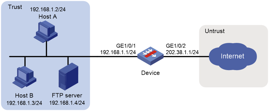
Requirements analysis
To allow external hosts to access the internal FTP server by using a public IP address, configure NAT Server on the interface connected to the external network.
To allow internal hosts to access the internal FTP server by using a public IP address, perform the following tasks:
· Enable NAT hairpin on the interface connected to the internal network.
· Configure outbound NAT on the interface where NAT Server is configured. The destination address is translated by matching the NAT server mapping. The source address is translated by matching the outbound NAT.
Procedure
1. Assign IP addresses to interfaces:
# Assign an IP address to interface GigabitEthernet 1/0/1.
<Device> system-view
[Device] interface gigabitethernet 1/0/1
[Device-GigabitEthernet1/0/1] ip address 10.110.10.1 24
[Device-GigabitEthernet1/0/1] quit
# Assign IP addresses to other interfaces in the same way. (Details not shown.)
2. Add interfaces to security zones.
[Device] security-zone name trust
[Device-security-zone-Trust] import interface gigabitethernet 1/0/1
[Device-security-zone-Trust] quit
[Device] security-zone name untrust
[Device-security-zone-Untrust] import interface gigabitethernet 1/0/2
[Device-security-zone-Untrust] quit
3. Configure a security policy:
# Configure a rule named trust-trust to permit the packets from the hosts to the server in the Trust security zone.
[Device] security-policy ip
[Device-security-policy-ip] rule name trust-trust
[Device-security-policy-ip-1-trust-trust] source-zone trust
[Device-security-policy-ip-1-trust-trust] destination-zone trust
[Device-security-policy-ip-1-trust-trust] source-ip-host 202.38.1.1
[Device-security-policy-ip-1-trust-trust] destination-ip-host 192.168.1.4
[Device-security-policy-ip-1-trust-trust] action pass
[Device-security-policy-ip-1-trust-trust] quit
4. Configure a security policy:
# Configure a rule named untrust-trust to permit the packets from the hosts in the Untrust security zone to the server.
[Device-security-policy-ip] rule name untrust-trust
[Device-security-policy-ip-2-untrust-trust] source-zone untrust
[Device-security-policy-ip-2-untrust-trust] destination-zone trust
[Device-security-policy-ip-2-untrust-trust] destination-ip-host 192.168.1.4
[Device-security-policy-ip-2-untrust-trust] action pass
[Device-security-policy-ip-2-untrust-trust] quit
[Device-security-policy-ip] quit
5. Configure NAT:
# Configure ACL 2000 to identify packets from subnet 192.168.1.0/24 to be translated.
[Device] acl basic 2000
[Device-acl-ipv4-basic-2000] rule permit source 192.168.1.0 0.0.0.255
[Device-acl-ipv4-basic-2000] quit
# Configure a NAT server mapping on GigabitEthernet 1/0/2 to map the IP address of the FTP server to a public address, allowing external users to access the internal FTP server.
[Device] interface gigabitethernet 1/0/2
[Device-GigabitEthernet1/0/2] nat server protocol tcp global 202.38.1.2 inside 192.168.1.4 ftp
# Enable outbound NAT with Easy IP on GigabitEthernet 1/0/2 so that NAT translates the source addresses of the packets from internal hosts into the IP address of interface GigabitEthernet 1/0/2.
[Device-GigabitEthernet1/0/2] nat outbound 2000
# Enable NAT hairpin on GigabitEthernet 1/0/1.
[Device] interface gigabitethernet 1/0/1
[Device-GigabitEthernet1/0/1] nat hairpin enable
[Device-GigabitEthernet1/0/1] quit
Verifying the configuration
# Verify that both internal and external hosts can access the internal FTP server through the public address. (Details not shown.)
# Display all NAT configuration and statistics.
[Device] display nat all
NAT outbound information:
Totally 1 NAT outbound rules.
Interface: GigabitEthernet1/0/2
ACL: 2000
Address group ID: ---
Port-preserved: N NO-PAT: N Reversible: N
Config status: Active
NAT internal server information:
Totally 1 internal servers.
Interface: GigabitEthernet1/0/2
Protocol: 6(TCP)
Global IP/port: 202.38.1.2/21
Local IP/port : 192.168.1.4/21
Rule name : ServerRule_1
NAT counting : 0
Config status : Active
NAT logging:
Log enable : Disabled
Flow-begin : Disabled
Flow-end : Disabled
Flow-active : Disabled
Port-block-assign : Disabled
Port-block-withdraw : Disabled
Alarm : Disabled
NO-PAT IP usage : Disabled
NAT hairpinning:
Totally 1 interfaces enabled with NAT hairpinning.
Interface: GigabitEthernet1/0/1
Config status: Active
NAT mapping behavior:
Mapping mode : Address and Port-Dependent
ACL : ---
Config status: Active
NAT ALG:
DNS : Enabled
FTP : Enabled
H323 : Disabled
ICMP-ERROR : Enabled
ILS : Disabled
MGCP : Disabled
NBT : Disabled
PPTP : Enabled
RTSP : Enabled
RSH : Disabled
SCCP : Disabled
SIP : Disabled
SQLNET : Disabled
TFTP : Disabled
XDMCP : Disabled
Static NAT load balancing: Disabled
# Display NAT sessions that are generated when Host A accesses the FTP server.
[Device] display nat session verbose
Slot 1:
Initiator:
Source IP/port: 192.168.1.2/1694
Destination IP/port: 202.38.1.2/21
DS-Lite tunnel peer: -
VPN instance/VLAN ID/Inline ID: -/-/-
Protocol: TCP(6)
Inbound interface: GigabitEthernet1/0/1
Source security zone: Trust
Responder:
Source IP/port: 192.168.1.4/21
Destination IP/port: 202.38.1.1/1025
DS-Lite tunnel peer: -
VPN instance/VLAN ID/Inline ID: -/-/-
Protocol: TCP(6)
Inbound interface: GigabitEthernet1/0/1
Source security zone: Trust
State: TCP_ESTABLISHED
Application: FTP
Rule ID: -/-/-
Rule name:
Start time: 2017-06-15 14:53:29 TTL: 3597s
Initiator->Responder: 7 packets 308 bytes
Responder->Initiator: 5 packets 312 bytes
Total sessions found: 1
Example: Configuring NAT hairpin in P2P mode
Network configuration
In the P2P application, internal clients must register their IP address to the external server and the server records the registered IP addresses and port numbers of the internal clients. An internal client must request the IP address and port number of another client from the external server before accessing the client.
Configure NAT hairpin so that:
· The internal clients can register the same public address to the external server.
· The internal clients can access each other through the IP address and port number obtained from the server.
Figure 26 Network diagram
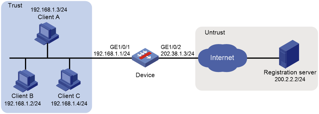
Requirements analysis
To meet the network requirements, you must perform the following tasks:
· Configure outbound dynamic PAT on the interface connected to the external network, so the internal clients can access the external server for registration.
· Configure the mapping behavior for PAT as Endpoint-Independent Mapping because the registered IP address and port number should be accessible for any source address.
· Enable NAT hairpin on the interface connected to the internal network so that internal clients can access each other through the public address.
Procedure
1. Assign IP addresses to interfaces:
# Assign an IP address to interface GigabitEthernet 1/0/1.
<Device> system-view
[Device] interface gigabitethernet 1/0/1
[Device-GigabitEthernet1/0/1] ip address 192.168.1.1 24
[Device-GigabitEthernet1/0/1] quit
# Assign IP addresses to other interfaces in the same way. (Details not shown.)
2. Add interfaces to security zones.
[Device] security-zone name trust
[Device-security-zone-Trust] import interface gigabitethernet 1/0/1
[Device-security-zone-Trust] quit
[Device] security-zone name untrust
[Device-security-zone-Untrust] import interface gigabitethernet 1/0/2
[Device-security-zone-Untrust] quit
3. Configure settings for routing.
This example configures a static route, and the next hop in the routes is 202.38.1.1.
[Device] ip route-static 200.2.2.0 24 202.38.1.1
4. Configure a security policy:
# Configure a rule named trust-untrust to permit the packets from the clients to the server.
[Device] security-policy ip
[Device-security-policy-ip] rule name trust-untrust
[Device-security-policy-ip-1-trust-untrust] source-zone trust
[Device-security-policy-ip-1-trust-untrust] destination-zone untrust
[Device-security-policy-ip-1-trust-untrust] source-ip-subnet 192.168.1.0 24
[Device-security-policy-ip-1-trust-untrust] destination-ip-host 200.2.2.2
[Device-security-policy-ip-1-trust-untrust] action pass
[Device-security-policy-ip-1-trust-untrust] quit
# Configure a rule named trust-trust to permit the packets between the clients in the Trust security zone.
[Device-security-policy-ip] rule name trust-trust
[Device-security-policy-ip-2-trust-trust] source-zone trust
[Device-security-policy-ip-2-trust-trust] destination-zone trust
[Device-security-policy-ip-2-trust-trust] source-ip-host 202.38.1.3
[Device-security-policy-ip-2-trust-trust] destination-ip-subnet 192.168.1.0 24
[Device-security-policy-ip-2-trust-trust] action pass
[Device-security-policy-ip-2-trust-trust] quit
[Device-security-policy-ip] quit
5. Configure NAT:
# Configure ACL 2000 to identify packets from subnet 192.168.1.0/24 to be translated.
[Device] acl basic 2000
[Device-acl-ipv4-basic-2000] rule permit source 192.168.1.0 0.0.0.255
[Device-acl-ipv4-basic-2000] quit
# Configure outbound dynamic PAT with Easy IP on GigabitEthernet 1/0/2. The IP address of GigabitEthernet 1/0/2 is used as the public address for the source address translation of the packets from internal to external.
[Device] interface gigabitethernet 1/0/2
[Device-GigabitEthernet1/0/2] nat outbound 2000
# Configure the Endpoint-Independent Mapping mode for PAT. For packets with the same source address and port number and permitted by ACL 2000, the source address and port number are translated to the same public address and port number.
[Device] nat mapping-behavior endpoint-independent acl 2000
# Enable NAT hairpin on GigabitEthernet 1/0/1.
[Device] interface gigabitethernet 1/0/1
[Device-GigabitEthernet1/0/1] nat hairpin enable
[Device-GigabitEthernet1/0/1] quit
Verifying the configuration
# Verify that Host A, Host B, and Host C can access each other after they register their IP addresses and port numbers to the external server. (Details not shown.)
# Display all NAT configuration and statistics.
[Device] display nat all
NAT outbound information:
Totally 1 NAT outbound rules.
Interface: GigabitEthernet1/0/2
ACL: 2000
Address group ID: ---
Port-preserved: N NO-PAT: N Reversible: N
Config status: Active
NAT logging:
Log enable : Disabled
Flow-begin : Disabled
Flow-end : Disabled
Flow-active : Disabled
Port-block-assign : Disabled
Port-block-withdraw : Disabled
Alarm : Disabled
NO-PAT IP usage : Disabled
NAT hairpinning:
Totally 1 interfaces enabled with NAT hairpinning.
Interface: GigabitEthernet1/0/1
Config status: Active
NAT mapping behavior:
Mapping mode : Endpoint-Independent
ACL : 2000
Config status: Active
NAT ALG:
DNS : Enabled
FTP : Enabled
H323 : Disabled
ICMP-ERROR : Enabled
ILS : Disabled
MGCP : Disabled
NBT : Disabled
PPTP : Enabled
RTSP : Enabled
RSH : Disabled
SCCP : Disabled
SIP : Disabled
SQLNET : Disabled
TFTP : Disabled
XDMCP : Disabled
Static NAT load balancing: Disabled
# Display NAT sessions that are generated when Client A accesses Client B.
[Device] display nat session verbose
Slot 1:
Initiator:
Source IP/port: 192.168.1.3/44929
Destination IP/port: 202.38.1.3/1
DS-Lite tunnel peer: -
VPN instance/VLAN ID/Inline ID: -/-/-
Protocol: UDP(17)
Inbound interface: GigabitEthernet1/0/1
Source security zone: Trust
Responder:
Source IP/port: 192.168.1.2/69
Destination IP/port: 202.38.1.3/1024
DS-Lite tunnel peer: -
VPN instance/VLAN ID/Inline ID: -/-/-
Protocol: UDP(17)
Inbound interface: GigabitEthernet1/0/1
Source security zone: Trust
State: UDP_READY
Application: TFTP
Rule ID: -/-/-
Rule name:
Start time: 2012-08-15 15:53:36 TTL: 46s
Initiator->Responder: 1 packets 56 bytes
Responder->Initiator: 1 packets 72 bytes
Total sessions found: 1
Example: Configuring twice NAT
Network configuration
As shown in Figure 27, two departments are in different VPN instances with overlapping addresses. Configure twice NAT so that Host A and Host B in different departments can access each other.
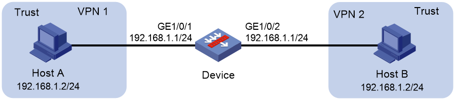
Requirements analysis
This is a typical application of twice NAT. Both the source and destination addresses of packets between the two VPNs need to be translated. Configure static NAT on both interfaces connected to the VPNs on the NAT device.
To allow VPNs to access each other, configure the interzone policies to allow VPN packets to pass through.
Procedure
1. Assign IP addresses to interfaces:
# Assign an IP address to interface GigabitEthernet 1/0/1.
<Device> system-view
[Device] interface gigabitethernet 1/0/1
[Device-GigabitEthernet1/0/1] ip binding vpn-instance vpn1
[Device-GigabitEthernet1/0/1] ip address 192.168.1.1 24
[Device-GigabitEthernet1/0/1] quit
# Assign IP addresses to other interfaces in the same way. (Details not shown.)
2. Add interfaces to security zones.
[Device] security-zone name trust
[Device-security-zone-Trust] import interface gigabitethernet 1/0/1
[Device-security-zone-Trust] import interface gigabitethernet 1/0/2
[Device-security-zone-Trust] quit
3. Configure a security policy:
# Configure a rule named vpn1-vpn2 to permit the packets from Host A to Host B.
[Device] security-policy ip
[Device-security-policy-ip] rule name vpn1-vpn2
[Device-security-policy-ip-1-vpn1-vpn2] source-zone trust
[Device-security-policy-ip-1-vpn1-vpn2] destination-zone trust
[Device-security-policy-ip-1-vpn1-vpn2] source-ip-host 192.168.1.2
[Device-security-policy-ip-1-vpn1-vpn2] destination-ip-host 192.168.1.2
[Device-security-policy-ip-1-vpn1-vpn2] vrf vpn1
[Device-security-policy-ip-1-vpn1-vpn2] action pass
[Device-security-policy-ip-1-vpn1-vpn2] quit
# Configure a rule named vpn2-vpn1 to permit the packets from Host B to Host A.
[Device-security-policy-ip] rule name vpn2-vpn1
[Device-security-policy-ip-1-vpn2-vpn1] source-zone trust
[Device-security-policy-ip-1-vpn2-vpn1] destination-zone trust
[Device-security-policy-ip-1-vpn2-vpn1] source-ip-host 192.168.1.2
[Device-security-policy-ip-1-vpn2-vpn1] destination-ip-host 192.168.1.2
[Device-security-policy-ip-1-vpn2-vpn1] vrf vpn2
[Device-security-policy-ip-1-vpn2-vpn1] action pass
[Device-security-policy-ip-1-vpn2-vpn1] quit
[Device-security-policy-ip] quit
4. Configure NAT:
# Configure a static outbound NAT mapping between 192.168.1.2 in vpn 1 and 172.16.1.2 in vpn 2.
[Device] nat static outbound 192.168.1.2 vpn-instance vpn1 172.16.1.2 vpn-instance vpn2
# Configure a static outbound NAT mapping between 192.168.1.2 in vpn 2 and 172.16.2.2 in vpn 1.
[Device] nat static outbound 192.168.1.2 vpn-instance vpn2 172.16.2.2 vpn-instance vpn1
# Enable static NAT on the two sides of the device.
[Device] interface gigabitethernet 1/0/2
[Device-GigabitEthernet1/0/2] nat static enable
[Device-GigabitEthernet1/0/2] quit
[Device] interface gigabitethernet 1/0/1
[Device-GigabitEthernet1/0/1] nat static enable
[Device-GigabitEthernet1/0/1] quit
Verifying the configuration
# Verify that Host A and Host B can access each other. The public address for Host A is 172.16.1.2 and that for Host B is 172.16.2.2. (Details not shown.)
# Display all NAT configuration and statistics.
[Device] display nat all
Static NAT mappings:
Totally 2 outbound static NAT mappings.
IP-to-IP:
Local IP : 192.168.1.2
Global IP : 172.16.1.2
Local VPN : vpn1
Global VPN : vpn2
Config status: Active
Local flow-table status: Active
Global flow-table status: Active
IP-to-IP:
Local IP : 192.168.1.2
Global IP : 172.16.2.2
Local VPN : vpn2
Global VPN : vpn1
Config status: Active
Local flow-table status: Active
Global flow-table status: Active
Interfaces enabled with static NAT:
Totally 2 interfaces enabled with static NAT.
Interface: GigabitEthernet1/0/1
Config status: Active
Interface: GigabitEthernet1/0/2
Config status: Active
NAT logging:
Log enable : Disabled
Flow-begin : Disabled
Flow-end : Disabled
Flow-active : Disabled
Port-block-assign : Disabled
Port-block-withdraw : Disabled
Alarm : Disabled
NO-PAT IP usage : Disabled
NAT mapping behavior:
Mapping mode : Address and Port-Dependent
ACL : ---
Config status: Active
NAT ALG:
DNS : Enabled
FTP : Enabled
H323 : Disabled
ICMP-ERROR : Enabled
ILS : Disabled
MGCP : Disabled
NBT : Disabled
PPTP : Enabled
RTSP : Enabled
RSH : Disabled
SCCP : Disabled
SIP : Disabled
SQLNET : Disabled
TFTP : Disabled
XDMCP : Disabled
Static NAT load balancing: Disabled
# Display NAT sessions that are generated when Host A accesses Host B.
[Device] display nat session verbose
Slot 1:
Initiator:
Source IP/port: 192.168.1.2/42496
Destination IP/port: 172.16.2.2/2048
DS-Lite tunnel peer: -
VPN instance/VLAN ID/Inline ID: vpn1/-/-
Protocol: ICMP(1)
Inbound interface: GigabitEthernet1/0/1
Source security zone: Trust
Responder:
Source IP/port: 192.168.1.2/42496
Destination IP/port: 172.16.1.2/0
DS-Lite tunnel peer: -
VPN instance/VLAN ID/Inline ID: vpn2/-/-
Protocol: ICMP(1)
Inbound interface: GigabitEthernet1/0/2
Source security zone: Trust
State: ICMP_REPLY
Application: INVALID
Rule ID: -/-/-
Rule name:
Start time: 2012-08-16 09:30:49 TTL: 27s
Initiator->Responder: 5 packets 420 bytes
Responder->Initiator: 5 packets 420 bytes
Total sessions found: 1
Example: Configuring load sharing NAT Server
Network configuration
As shown in Figure 28, three FTP servers are in the intranet to provide FTP services for external users. Configure NAT so that these external users use the address 202.38.1.1/16 to access the servers and the three FTP servers implement load sharing.
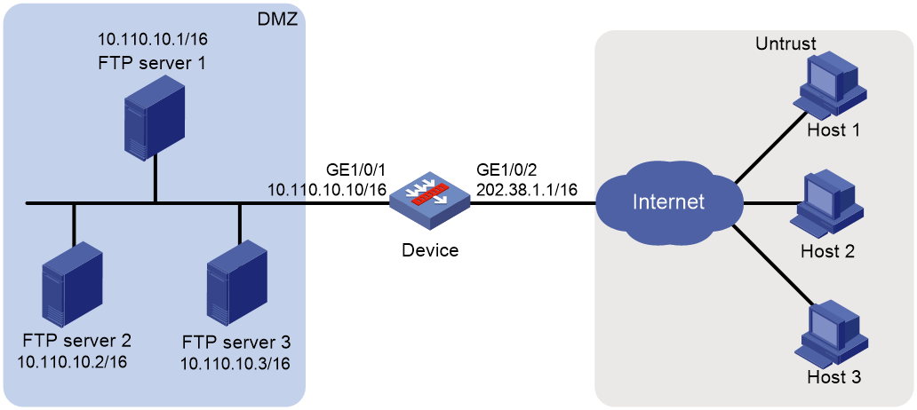
Procedure
1. Assign IP addresses to interfaces:
# Assign an IP address to interface GigabitEthernet 1/0/1.
<Device> system-view
[Device] interface gigabitethernet 1/0/1
[Device-GigabitEthernet1/0/1] ip address 10.110.10.10 16
[Device-GigabitEthernet1/0/1] quit
# Assign IP addresses to other interfaces in the same way. (Details not shown.)
2. Add interfaces to security zones.
[Device] security-zone name dmz
[Device-security-zone-DMZ] import interface gigabitethernet 1/0/1
[Device-security-zone-DMZ] quit
[Device] security-zone name untrust
[Device-security-zone-Untrust] import interface gigabitethernet 1/0/2
[Device-security-zone-Untrust] quit
3. Configure a security policy:
# Configure a rule named untrust-dmz to permit the packets from the hosts to the servers.
[Device] security-policy ip
[Device-security-policy-ip] rule name untrust-dmz
[Device-security-policy-ip-1-untrust-dmz] source-zone untrust
[Device-security-policy-ip-1-untrust-dmz] destination-zone dmz
[Device-security-policy-ip-1-untrust-dmz] destination-ip-host 10.110.10.1
[Device-security-policy-ip-1-untrust-dmz] destination-ip-host 10.110.10.2
[Device-security-policy-ip-1-untrust-dmz] destination-ip-host 10.110.10.3
[Device-security-policy-ip-1-untrust-dmz] action pass
[Device-security-policy-ip-1-untrust-dmz] quit
[Device-security-policy-ip] quit
4. Configure NAT:
# Create NAT server group 0, and add members to the group.
[Device] nat server-group 0
[Device-nat-server-group-0] inside ip 10.110.10.1 port 21
[Device-nat-server-group-0] inside ip 10.110.10.2 port 21
[Device-nat-server-group-0] inside ip 10.110.10.3 port 21
[Device-nat-server-group-0] quit
# Associate NAT server group 0 with GigabitEthernet 1/0/2 so that servers in the server group can provide FTP services.
[Device] interface gigabitethernet 1/0/2
[Device-GigabitEthernet1/0/2] nat server protocol tcp global 202.38.1.1 ftp inside server-group 0
[Device-GigabitEthernet1/0/2] quit
Verifying the configuration
# Verify that external hosts can access the internal FTP server group. (Details not shown.)
# Display all NAT configuration and statistics.
[Device] display nat all
NAT server group information:
Totally 1 NAT server groups.
Group Number Inside IP Port Weight
0 10.110.10.1 21 100
10.110.10.2 21 100
10.110.10.3 21 100
NAT internal server information:
Totally 1 internal servers.
Interface: GigabitEthernet1/0/2
Protocol: 6(TCP)
Global IP/port: 202.38.1.1/21
Local IP/port : server group 0
10.110.10.1/21 (Connections: 1)
10.110.10.2/21 (Connections: 1)
10.110.10.3/21 (Connections: 1)
Rule name : ServerRule_1
NAT counting : 0
Config status : Active
NAT logging:
Log enable : Disabled
Flow-begin : Disabled
Flow-end : Disabled
Flow-active : Disabled
Port-block-assign : Disabled
Port-block-withdraw : Disabled
Alarm : Disabled
NO-PAT IP usage : Disabled
NAT mapping behavior:
Mapping mode : Address and Port-Dependent
ACL : ---
Config status: Active
NAT ALG:
DNS : Enabled
FTP : Enabled
H323 : Disabled
ICMP-ERROR : Enabled
ILS : Disabled
MGCP : Disabled
NBT : Disabled
PPTP : Enabled
RTSP : Enabled
RSH : Disabled
SCCP : Disabled
SIP : Disabled
SQLNET : Disabled
TFTP : Disabled
XDMCP : Disabled
Static NAT load balancing: Disabled
# Display NAT sessions that are generated when external hosts access an internal FTP server.
[Device] display nat session verbose
Slot 1:
Initiator:
Source IP/port: 202.38.1.27/5760
Destination IP/port: 202.38.1.1/21
DS-Lite tunnel peer: -
VPN instance/VLAN ID/Inline ID: -/-/-
Protocol: TCP(6)
Inbound interface: GigabitEthernet1/0/2
Source security zone: Untrust
Responder:
Source IP/port: 10.110.10.3/21
Destination IP/port: 202.38.1.27/5760
DS-Lite tunnel peer: -
VPN instance/VLAN ID/Inline ID: -/-/-
Protocol: TCP(6)
Inbound interface: GigabitEthernet1/0/1
Source security zone: DMZ
State: TCP_ESTABLISHED
Application: FTP
Rule ID: -/-/-
Rule name:
Start time: 2017-05-19 16:10:27 TTL: 3598s
Initiator->Responder: 15 packets 702 bytes
Responder->Initiator: 16 packets 891 bytes
Initiator:
Source IP/port: 202.38.1.26/30018
Destination IP/port: 202.38.1.1/21
DS-Lite tunnel peer: -
VPN instance/VLAN ID/Inline ID: -/-/-
Protocol: TCP(6)
Inbound interface: GigabitEthernet1/0/2
Source security zone: Untrust
Responder:
Source IP/port: 10.110.10.2/21
Destination IP/port: 202.38.1.26/30018
DS-Lite tunnel peer: -
VPN instance/VLAN ID/Inline ID: -/-/-
Protocol: TCP(6)
Inbound interface: GigabitEthernet1/0/1
Source security zone: DMZ
State: TCP_ESTABLISHED
Application: FTP
Start time: 2017-05-19 16:09:58 TTL: 3576s
Initiator->Responder: 15 packets 702 bytes
Responder->Initiator: 16 packets 891 bytes
Initiator:
Source IP/port: 202.38.1.25/35652
Destination IP/port: 202.38.1.1/21
DS-Lite tunnel peer: -
VPN instance/VLAN ID/Inline ID: -/-/-
Protocol: TCP(6)
Inbound interface: GigabitEthernet1/0/2
Source security zone: Untrust
Responder:
Source IP/port: 10.110.10.1/21
Destination IP/port: 202.38.1.25/35652
DS-Lite tunnel peer: -
VPN instance/VLAN ID/Inline ID: -/-/-
Protocol: TCP(6)
Inbound interface: GigabitEthernet1/0/1
Source security zone: DMZ
State: TCP_ESTABLISHED
Application: FTP
Start time: 2017-05-19 16:09:46 TTL: 3579s
Initiator->Responder: 15 packets 702 bytes
Responder->Initiator: 16 packets 891 bytes
Total sessions found: 3
Example: Configuring NAT DNS mapping
Network configuration
As shown in Figure 29, the internal Web server at 10.110.10.1/16 and FTP server at 10.110.10.2/16 provide services for external user. The company has three public addresses 202.38.1.1 through 202.38.1.3. The DNS server at 202.38.1.4 is on the external network.
Configure NAT so that:
· The public IP address 202.38.1.2 is used by external users to access the Web and FTP servers.
· External users can use the public address or domain name of internal servers to access them.
· Internal users can access the internal servers by using their domain names.
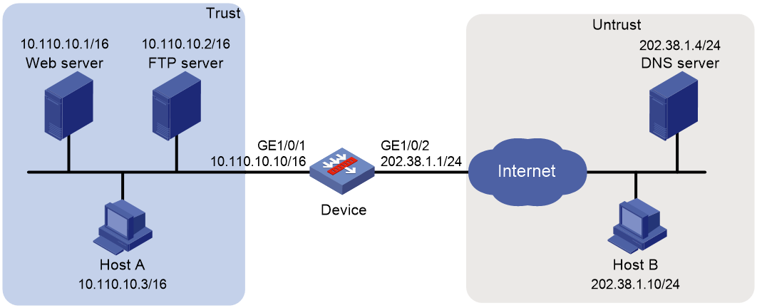
Requirements analysis
To meet the network requirements, perform the following tasks:
· Configure a NAT server mapping by mapping the public IP addresses and port numbers of the internal servers to a public address and port numbers so that external users can access the internal servers.
· Configure NAT DNS mapping and NAT ALG so that the public IP address of the internal server in the payload of the DNS response packet can be translated to the private IP address.
Procedure
1. Assign IP addresses to interfaces:
# Assign an IP address to interface GigabitEthernet 1/0/1.
<Device> system-view
[Device] interface gigabitethernet 1/0/1
[Device-GigabitEthernet1/0/1] ip address 10.110.10.10 16
[Device-GigabitEthernet1/0/1] quit
# Assign IP addresses to other interfaces in the same way. (Details not shown.)
2. Add interfaces to security zones.
[Device] security-zone name trust
[Device-security-zone-Trust] import interface gigabitethernet 1/0/1
[Device-security-zone-Trust] quit
[Device] security-zone name untrust
[Device-security-zone-Untrust] import interface gigabitethernet 1/0/2
[Device-security-zone-Untrust] quit
3. Configure a security policy:
# Configure a rule named trust-untrust to permit the packets from Host A to the DNS server.
[Device] security-policy ip
[Device-security-policy-ip] rule name trust-untrust
[Device-security-policy-ip-1-trust-untrust] source-zone trust
[Device-security-policy-ip-1-trust-untrust] destination-zone untrust
[Device-security-policy-ip-1-trust-untrust] source-ip-subnet 10.110.0.0 16
[Device-security-policy-ip-1-trust-untrust] destination-ip-host 202.38.1.4
[Device-security-policy-ip-1-trust-untrust] action pass
[Device-security-policy-ip-1-trust-untrust] quit
# Configure a rule named untrust-trust to permit the packets from Host B to the servers in the Trust security zone.
[Device-security-policy-ip] rule name untrust-trust
[Device-security-policy-ip-2-untrust-trust] source-zone untrust
[Device-security-policy-ip-2-untrust-trust] destination-zone trust
[Device-security-policy-ip-2-untrust-trust] destination-ip-host 10.110.10.1
[Device-security-policy-ip-2-untrust-trust] destination-ip-host 10.110.10.2
[Device-security-policy-ip-2-untrust-trust] action pass
[Device-security-policy-ip-2-untrust-trust] quit
# Configure a rule named trust-trust to permit the packets from Host A to the servers in the Trust security zone.
[Device-security-policy-ip] rule name trust-trust
[Device-security-policy-ip-3-trust-trust] source-zone trust
[Device-security-policy-ip-3-trust-trust] destination-zone trust
[Device-security-policy-ip-3-trust-trust] source-ip-host 202.38.1.1
[Device-security-policy-ip-3-trust-trust] destination-ip-host 10.110.10.1
[Device-security-policy-ip-3-trust-trust] destination-ip-host 10.110.10.2
[Device-security-policy-ip-3-trust-trust] action pass
[Device-security-policy-ip-3-trust-trust] quit
[Device-security-policy-ip] quit
4. Configure NAT:
# Enable NAT ALG for DNS.
[Device] nat alg dns
# Configure a NAT server mapping to allow external hosts to access the internal Web server by using the address 202.38.1.2.
[Device] interface gigabitethernet 1/0/2
[Device-GigabitEthernet1/0/2] nat server protocol tcp global 202.38.1.2 inside 10.110.10.1 http
# Configure a NAT server mapping to allow external hosts to access the internal FTP server by using the address 202.38.1.2.
[Device-GigabitEthernet1/0/2] nat server protocol tcp global 202.38.1.2 inside 10.110.10.2 ftp
# Enable outbound NAT with Easy IP on GigabitEthernet 1/0/2.
[Device-GigabitEthernet1/0/2] nat outbound
# Configure two NAT DNS entries by mapping the domain name www.server.com of the Web server to 202.38.1.2, and ftp.server.com of the FTP server to 202.38.1.2.
[Device] nat dns-map domain www.server.com protocol tcp ip 202.38.1.2 port http
[Device] nat dns-map domain ftp.server.com protocol tcp ip 202.38.1.2 port ftp
[Device] quit
Verifying the configuration
# Verify that both internal and external hosts can access the internal servers by using domain names. (Details not shown.)
# Display all NAT configuration and statistics.
[Device] display nat all
NAT outbound information:
Totally 1 NAT outbound rules.
Interface: GigabitEthernet1/0/2
ACL: ---
Address group ID: ---
Port-preserved: N NO-PAT: N Reversible: N
Config status: Active
NAT internal server information:
Totally 2 internal servers.
Interface: GigabitEthernet1/0/2
Protocol: 6(TCP)
Global IP/port: 202.38.1.2/21
Local IP/port : 10.110.10.2/21
Rule name : ServerRule_2
NAT counting : 0
Config status : Active
Interface: GigabitEthernet1/0/2
Protocol: 6(TCP)
Global IP/port: 202.38.1.2/80
Local IP/port : 10.110.10.1/80
Rule name : ServerRule_1
NAT counting : 0
Config status : Active
NAT DNS mapping information:
Totally 2 NAT DNS mappings.
Domain name: ftp.server.com
Global IP : 202.38.1.2
Global port: 21
Protocol : TCP(6)
Config status: Active
Domain name: www.server.com
Global IP : 202.38.1.2
Global port: 80
Protocol : TCP(6)
Config status: Active
NAT logging:
Log enable : Disabled
Flow-begin : Disabled
Flow-end : Disabled
Flow-active : Disabled
Port-block-assign : Disabled
Port-block-withdraw : Disabled
Alarm : Disabled
NO-PAT IP usage : Disabled
NAT mapping behavior:
Mapping mode : Address and Port-Dependent
ACL : ---
Config status: Active
NAT ALG:
DNS : Enabled
FTP : Enabled
H323 : Disabled
ICMP-ERROR : Enabled
ILS : Disabled
MGCP : Disabled
NBT : Disabled
PPTP : Enabled
RTSP : Enabled
RSH : Disabled
SCCP : Disabled
SIP : Disabled
SQLNET : Disabled
TFTP : Disabled
XDMCP : Disabled
Static NAT load balancing: Disabled
# Verify that NAT sessions have been created for external host access to internal Web server.
[Device] display nat session verbose
Slot 1:
Initiator:
Source IP/port: 202.38.1.10/63593
Destination IP/port: 202.38.1.2/80
DS-Lite tunnel peer: -
VPN instance/VLAN ID/Inline ID: -/-/-
Protocol: TCP(6)
Inbound interface: GigabitEthernet1/0/2
Source security zone: Untrust
Responder:
Source IP/port: 10.110.10.1/80
Destination IP/port: 202.38.1.10/63593
DS-Lite tunnel peer: -
VPN instance/VLAN ID/Inline ID: -/-/-
Protocol: TCP(6)
Inbound interface: GigabitEthernet1/0/1
Source security zone: Trust
State: TCP_ESTABLISHED
Application: HTTP
Rule ID: -/-/-
Rule name:
Start time: 2017-05-21 15:09:11 TTL: 11s
Initiator->Responder: 5 packets 1145 bytes
Responder->Initiator: 3 packets 1664 bytes
Total sessions found: 1
Example: Configuring static port block mapping NAT444
Network configuration
As shown in Figure 30, configure static NAT444 to allow users at private IP addresses 10.110.10.1 to 10.110.10.10 to use public IP address 202.38.1.100 for accessing Sever at 200.2.2.1 on the Internet. Configure the port range as 10001 to 15000, and set the port block size to 500.
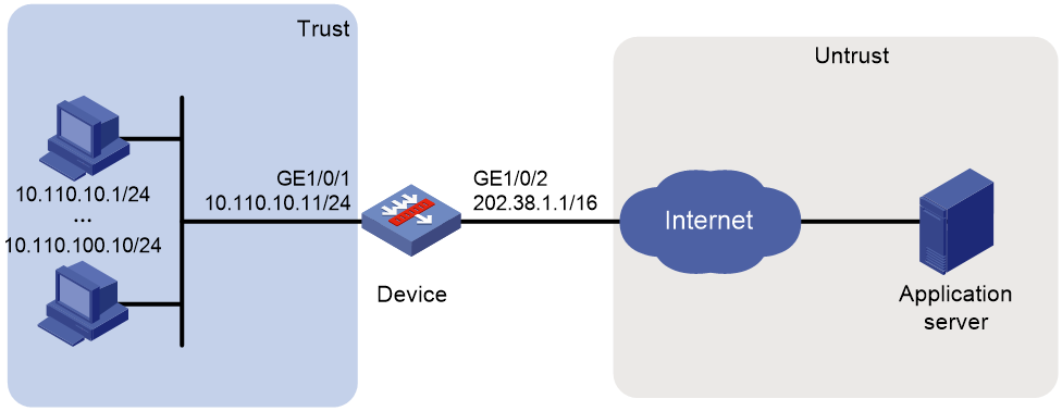
Procedure
1. Assign IP addresses to interfaces:
# Assign an IP address to interface GigabitEthernet 1/0/1.
<Device> system-view
[Device] interface gigabitethernet 1/0/1
[Device-GigabitEthernet1/0/1] ip address 10.110.10.11 24
[Device-GigabitEthernet1/0/1] quit
# Assign IP addresses to other interfaces in the same way. (Details not shown.)
2. Add interfaces to security zones.
[Device] security-zone name trust
[Device-security-zone-Trust] import interface gigabitethernet 1/0/1
[Device-security-zone-Trust] quit
[Device] security-zone name untrust
[Device-security-zone-Untrust] import interface gigabitethernet 1/0/2
[Device-security-zone-Untrust] quit
3. Configure settings for routing.
This example configures a static route, and the next hop in the routes is 202.38.1.2.
[Device] ip route-static 200.2.2.1 32 202.38.1.2
4. Configure a security policy:
# Configure a rule named trust-untrust to permit the packets from the hosts to the application server.
[Device] security-policy ip
[Device-security-policy-ip] rule name trust-untrust
[Device-security-policy-ip-1-trust-untrust] source-zone trust
[Device-security-policy-ip-1-trust-untrust] destination-zone untrust
[Device-security-policy-ip-1-trust-untrust] source-ip-range 10.110.10.1 10.110.10.10
[Device-security-policy-ip-1-trust-untrust] destination-ip-host 200.2.2.1
[Device-security-policy-ip-1-trust-untrust] action pass
[Device-security-policy-ip-1-trust-untrust] quit
[Device-security-policy-ip] quit
5. Configure NAT:
# Create NAT port block group 1.
[Device] nat port-block-group 1
# Add the private IP addresses from 10.110.10.1 to 10.110.10.10 to the port block group.
[Device-port-block-group-1] local-ip-address 10.110.10.1 10.110.10.10
# Add the public IP address 202.38.1.100 to the port block group.
[Device-port-block-group-1] global-ip-pool 202.38.1.100 202.38.1.100
# Set the port block size to 500.
[Device-port-block-group-1] block-size 500
# Configure the port range as 10001 to 15000.
[Device-port-block-group-1] port-range 10001 15000
[Device-port-block-group-1] quit
# Configure a static outbound port block mapping on GigabitEthernet 1/0/2.
[Device] interface gigabitethernet 1/0/2
[Device-GigabitEthernet1/0/2] nat outbound port-block-group 1
[Device-GigabitEthernet1/0/2] quit
Verifying the configuration
# Verify that users at the private IP addresses can access the Internet. (Details not shown.)
# Display all NAT configuration and statistics.
[Device] display nat all
NAT logging:
Log enable : Disabled
Flow-begin : Disabled
Flow-end : Disabled
Flow-active : Disabled
Port-block-assign : Disabled
Port-block-withdraw : Disabled
Alarm : Disabled
NO-PAT IP usage : Disabled
NAT mapping behavior:
Mapping mode : Address and Port-Dependent
ACL : ---
Config status: Active
NAT ALG:
DNS : Enabled
FTP : Enabled
H323 : Disabled
ICMP-ERROR : Enabled
ILS : Disabled
MGCP : Disabled
NBT : Disabled
PPTP : Enabled
RTSP : Enabled
RSH : Disabled
SCCP : Disabled
SIP : Disabled
SQLNET : Disabled
TFTP : Disabled
XDMCP : Disabled
NAT port block group information:
Totally 1 NAT port block groups.
Port block group 1:
Port range: 10001-15000
Block size: 500
Local IP address information:
Start address End address VPN instance
10.110.10.1 10.110.10.10 ---
Global IP pool information:
Start address End address
202.38.1.100 202.38.1.100
NAT outbound port block group information:
Totally 1 outbound port block group items.
Interface: GigabitEthernet1/0/2
port-block-group: 1
Config status : Active
Static NAT load balancing: Disabled
# Display static NAT444 mappings.
[Device] display nat port-block static
Slot 1:
Local VPN Local IP Global IP Port block Connections
--- 10.110.10.7 202.38.1.100 13001-13500 1
--- 10.110.10.5 202.38.1.100 12001-12500 1
--- 10.110.10.9 202.38.1.100 14001-14500 1
--- 10.110.10.3 202.38.1.100 11001-11500 1
--- 10.110.10.2 202.38.1.100 10501-11000 1
--- 10.110.10.4 202.38.1.100 11501-12000 1
--- 10.110.10.6 202.38.1.100 12501-13000 1
--- 10.110.10.1 202.38.1.100 10001-10500 1
--- 10.110.10.10 202.38.1.100 14501-15000 1
--- 10.110.10.8 202.38.1.100 13501-14000 1
Total mappings found: 10
Example: Configuring dynamic port block mapping for NAT444
Network configuration
As shown in Figure 31, a company uses private IP address on network 192.168.0.0/16 and public IP addresses 202.38.1.2 and 202.38.1.3. Configure dynamic NAT444 to meet the following requirements:
· Only users on subnet 192.168.1.0/24 can use public IP addresses 202.38.1.2 and 202.38.1.3 to access the server at 200.2.2.1 on the Internet.
· The port range for the public IP addresses is 1024 to 65535.
· The port block size is 300.
· If the ports in the assigned port block are all used, extend another port block for users.

Procedure
1. Assign IP addresses to interfaces:
# Assign an IP address to interface GigabitEthernet 1/0/1.
<Device> system-view
[Device] interface gigabitethernet 1/0/1
[Device-GigabitEthernet1/0/1] ip address 192.168.1.1 16
[Device-GigabitEthernet1/0/1] quit
# Assign IP addresses to other interfaces in the same way. (Details not shown.)
2. Add interfaces to security zones.
[Device] security-zone name trust
[Device-security-zone-Trust] import interface gigabitethernet 1/0/1
[Device-security-zone-Trust] quit
[Device] security-zone name untrust
[Device-security-zone-Untrust] import interface gigabitethernet 1/0/2
[Device-security-zone-Untrust] quit
3. Configure settings for routing.
This example configures a static route, and the next hop in the routes is 202.38.1.20.
[Device] ip route-static 200.2.2.1 32 202.38.1.20
4. Configure a security policy:
# Configure a rule named trust-untrust to permit the packets from the hosts to the application server.
[Device] security-policy ip
[Device-security-policy-ip] rule name trust-untrust
[Device-security-policy-ip-1-trust-untrust] source-zone trust
[Device-security-policy-ip-1-trust-untrust] destination-zone untrust
[Device-security-policy-ip-1-trust-untrust] source-ip-subnet 192.168.1.0 24
[Device-security-policy-ip-1-trust-untrust] destination-ip-host 200.2.2.1
[Device-security-policy-ip-1-trust-untrust] action pass
[Device-security-policy-ip-1-trust-untrust] quit
[Device-security-policy-ip] quit
5. Configure NAT:
# Create NAT address group 0.
[Device] nat address-group 0
# Add public IP addresses 202.38.1.2 and 202.38.1.3 to the NAT address group.
[Device-address-group-0] address 202.38.1.2 202.38.1.3
# Configure the port range as 1024 to 65535.
[Device-address-group-0] port-range 1024 65535
# Set the port block size to 300 and the extended port block number to 1.
[Device-address-group-0] port-block block-size 300 extended-block-number 1
[Device-address-group-0] quit
# Configure an ACL to identify packets from subnet 192.168.1.0/24.
[Device] acl basic 2000
[Device-acl-ipv4-basic-2000] rule permit source 192.168.1.0 0.0.0.255
[Device-acl-ipv4-basic-2000] quit
# Configure outbound NAT on GigabitEthernet 1/0/2.
[Device] interface gigabitethernet 1/0/2
[Device-GigabitEthernet1/0/2] nat outbound 2000 address-group 0
[Device-GigabitEthernet1/0/2] quit
Verifying the configuration
# Verify that Host A can access external servers, but Host B and Host C cannot. (Details not shown.)
# Display all NAT configurations and statistics.
[Device] display nat all
NAT address group information:
Totally 1 NAT address groups.
Address group ID: 0
Port range: 1024-65535
Blade-load-sharing-group: Blade4fw-m90001
Port block size: 300
Extended block number: 1
Address information:
Start address End address
202.38.1.2 202.38.1.3
NAT outbound information:
Totally 1 NAT outbound rules.
Interface: GigabitEthernet1/0/2
ACL: 2000
Address group ID: 0
Port-preserved: N NO-PAT: N Reversible: N
Config status: Active
NAT logging:
Log enable : Disabled
Flow-begin : Disabled
Flow-end : Disabled
Flow-active : Disabled
Port-block-assign : Disabled
Port-block-withdraw : Disabled
Alarm : Disabled
NO-PAT IP usage : Disabled
NAT mapping behavior:
Mapping mode : Address and Port-Dependent
ACL : ---
Config status: Active
NAT ALG:
DNS : Enabled
FTP : Enabled
H323 : Disabled
ICMP-ERROR : Enabled
ILS : Disabled
MGCP : Disabled
NBT : Disabled
PPTP : Enabled
RTSP : Enabled
RSH : Disabled
SCCP : Disabled
SIP : Disabled
SQLNET : Disabled
TFTP : Disabled
XDMCP : Disabled
Static NAT load balancing: Disabled
# Display NAT statistics.
[Device] display nat statistics
Total session entries: 1
Session creation rate: 0
Total EIM entries: 0
Total inbound NO-PAT entries: 0
Total outbound NO-PAT entries: 0
Total static port block entries: 0
Total dynamic port block entries: 430
Active static port block entries: 0
Active dynamic port block entries: 1
# Display the dynamic port block entries.
[Device] display nat port-block dynamic
Slot 1:
Local VPN Local IP Global IP Port block Connections
--- 192.168.1.10 202.38.1.2 65224-65523 1
Total mappings found: 1
Example: Configuring DS-Lite B4 address translation
Network configuration
As shown in Figure 32, configure DS-Lite tunneling and NAT to allow the DS-Lite host to access the IPv4 network over the IPv6 network.
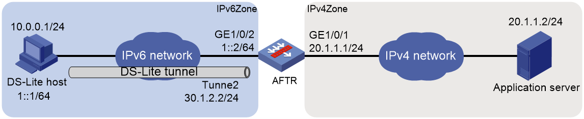
Restrictions and guidelines
Add DS-Lite tunnel interfaces to security zones, and allow traffic between zone pairs to pass through. In this example, Tunnel 2 is added to security zone IPv6Zone, and allow traffic between zones IPv6Zone and IPv4Zone.
Procedure
1. Configure the AFTR:
a. Assign IP addresses to interfaces:
# Assign IP addresses to interfaces GigabitEthernet 1/0/1 and GigabitEthernet 1/0/2.
<Device> system-view
[Device] interface gigabitethernet 1/0/1
[Device-GigabitEthernet1/0/1] ip address 20.1.1.1 24
[Device-GigabitEthernet1/0/1] quit
[Device] interface gigabitethernet 1/0/2
[Device-GigabitEthernet1/0/2] ipv6 address 1::2 64
[Device-GigabitEthernet1/0/2] quit
# Create a tunnel interface on the AFTR.
[Device] interface tunnel 2 mode ds-lite-aftr
# Specify an IP address for the tunnel interface.
[Device-Tunnel2] ip address 30.1.2.2 255.255.255.0
# Specify GigabitEthernet 1/0/2 as the source interface for the tunnel.
[Device-Tunnel2] source gigabitethernet 1/0/2
[Device-Tunnel2] quit
b. Add interfaces to security zones.
[Device] security-zone name IPv4Zone
[Device-security-zone-IPv4Zone] import interface gigabitethernet 1/0/1
[Device-security-zone-IPv4Zone] quit
[Device] security-zone name IPv6Zone
[Device-security-zone-IPv6Zone] import interface gigabitethernet 1/0/2
[Device-security-zone-IPv6Zone] import interface Tunnel 2
[Device-security-zone-IPv6Zone] quit
c. Configure a security policy:
# Configure a rule named v6-v4 to permit the packets from the host to the application server.
[Device] security-policy ip
[Device-security-policy-ip] rule name v6-v4
[Device-security-policy-ip-1-v6-v4] source-zone IPv6Zone
[Device-security-policy-ip-1-v6-v4] destination-zone IPv4Zone
[Device-security-policy-ip-1-v6-v4] source-ip-host 10.0.0.1
[Device-security-policy-ip-1-v6-v4] destination-ip-host 20.1.1.2
[Device-security-policy-ip-1-v6-v4] action pass
[Device-security-policy-ip-1-v6-v4] quit
[Device-security-policy-ip] quit
# Configure a rule named v6-local to allow the device to encapsulate and decapsulate the packets transmitted through the DS-Lite tunnel.
[Device] security-policy ipv6
[Device-security-policy-ipv6] rule name v6-local
[Device-security-policy-ipv6-1-v6-local] source-zone IPv6Zone
[Device-security-policy-ipv6-1-v6-local] destination-zone local
[Device-security-policy-ipv6-1-v6-local] source-ip-host 1::1
[Device-security-policy-ipv6-1-v6-local] destination-ip-host 1::2
[Device-security-policy-ipv6-1-v6-local] action pass
[Device-security-policy-ipv6-1-v6-local] quit
[Device-security-policy-ipv6] quit
d. Enable DS-Lite tunneling:
# Enable DS-Lite tunneling on GigabitEthernet 1/0/1.
[Device] interface gigabitethernet 1/0/1
[Device-GigabitEthernet1/0/1] ds-lite enable
[Device-GigabitEthernet1/0/1] quit
e. Configure NAT:
# Create public address group 0.
[AFTR] nat address-group 0
# Add public IP addresses 20.1.1.11 and 20.1.1.12 to the NAT address group.
[AFTR-address-group-0] address 20.1.1.11 20.1.1.12
# Configure the port range as 1024 to 65535.
[AFTR-address-group-0] port-range 1024 65535
# Set the port block size to 300.
[AFTR-address-group-0] port-block block-size 300
[AFTR-address-group-0] quit
# Configure an IPv6 ACL to identify packets from subnet 1::/64.
[AFTR] acl ipv6 basic 2100
[AFTR-acl-ipv4-basic-2100] rule permit source 1::/64
[AFTR-acl-ipv4-basic-2100] quit
# Configure DS-Lite NAT444 on GigabitEthernet 1/0/1.
[AFTR] interface gigabitethernet 1/0/1
[AFTR-GigabitEthernet1/0/1] nat outbound ds-lite-b4 2100 address-group 0
[AFTR-GigabitEthernet1/0/1] quit
2. Configure the DS-Lite host:
# Configure the IPv4 and IPv6 addresses of the DS-Lite host as 10.0.0.1 and 1::1/64. (Details not shown.)
# Configure a static route to the destination IPv4 network. (Details not shown.)
Verifying the configuration
# Use the display tunnel interface command to verify that the tunnel interface is up on the AFTR. (Details not shown.)
# Verify that the DS-Lite host can ping the IPv4 application server.
C:\> ping 20.1.1.2
Pinging 20.1.1.2 with 32 bytes of data:
Reply from 20.1.1.2: bytes=32 time=51ms TTL=255
Reply from 20.1.1.2: bytes=32 time=44ms TTL=255
Reply from 20.1.1.2: bytes=32 time=1ms TTL=255
Reply from 20.1.1.2: bytes=32 time=1ms TTL=255
Ping statistics for 20.1.1.2:
Packets: Sent = 4, Received = 4, Lost = 0 (0% loss),
Approximate round trip times in milli-seconds:
Minimum = 1ms, Maximum = 51ms, Average = 24ms
# Verify that the DS-Lite NAT444 configuration is correct.
[AFTR] display nat outbound
NAT outbound information:
Totally 1 NAT outbound rules.
Interface: GigabitEthernet1/0/1
DS-Lite B4 ACL: 2100
Address group ID: 0
Port-preserved: N NO-PAT: N Reversible: N
Config status: Active
# Verify that the DS-Lite NAT444 configuration takes effect by checking the port block assignment.
[AFTR] display nat statistics
Slot 1:
Total session entries: 1
Session creation rate: 0
Total EIM entries: 0
Total inbound NO-PAT entries: 0
Total outbound NO-PAT entries: 0
Total static port block entries: 0
Total dynamic port block entries: 430
Active static port block entries: 0
Active dynamic port block entries: 1
# Verify that a NAT444 mapping has been created for the DS-Lite host.
[Device] display nat port-block dynamic ds-lite-b4
Slot 1:
Local VPN DS-Lite B4 addr Global IP Port block Connections
--- 1::1 20.1.1.11 65224-65523 1
Total mappings found: 1
Example: Configuring an HA group in active/standby mode in collaboration with VRRP for NAT
For more information, see high availability group configuration in High Availability Configuration Guide.
Example: Configuring an HA group in dual-active mode in collaboration with VRRP for NAT
For more information, see high availability group configuration in High Availability Configuration Guide.
