- Table of Contents
- Related Documents
-
| Title | Size | Download |
|---|---|---|
| 01-High availability group configuration | 1.05 MB |
Contents
Operating modes of the HA group
Associating the HA group with VRRP
Associating the HA group with routing protocols
Transparent in-path deployment of the HA group
Restrictions: Hardware compatibility with the HA group
Restrictions and guidelines: HA group configuration
Member device restrictions and guidelines
Configuration synchronization restrictions and guidelines
Interface restrictions and guidelines
HA channel restrictions and guidelines
HA group deployment restrictions and guidelines
Feature compatibility restrictions
Hardware environment consistency
Software environment consistency
Network interconnection restrictions
Configuring the HA control channel
Configuring the HA data channel
Enabling service entry hot backup
Configuring HA configuration synchronization
Enabling traffic switchover upon failure recovery
Configuring the active/standby mode
Configuring the dual-active mode
Associating the HA group with VRRP
Associating the HA group with routing protocols
Enabling the HA group to adjust the link cost for a routing protocol
Disabling the standby device from sending or receiving protocol packets of a routing protocol.
Configuring HA group transparent in-path deployment
Enabling the HA group to monitor interfaces
Enabling the HA group to monitor VLANs
Associating the HA group with Track
Performing an active/standby switchover
Enabling transparent service traffic transmission between the HA group members
Configuring service features on the HA group
HA group support for DPI services
Routed in-path deployment in active/standby mode
Routed in-path deployment in dual-active mode
Transparent in-path deployment in active/standby mode
Transparent in-path deployment in dual-active mode
Display and maintenance commands for the HA group
HA group configuration examples (IPv4)
Example: Configuring the HA group in active/standby mode in collaboration with VRRP
Example: Configuring the HA group in dual-active mode in collaboration with VRRP
Example: Configuring the HA group in active/standby mode in collaboration with a routing protocol
Example: Configuring the HA group in dual-active mode in collaboration with a routing protocol
Example: Configuring a transparent in-path HA group in active/standby mode
Example: Configuring a transparent in-path HA group in dual-active mode
Example: Configuring global NAT on the HA group in active/standby mode in collaboration with VRRP
Example: Configuring global NAT on the HA group in dual-active mode in collaboration with VRRP
HA group configuration examples (IPv6)
Example: Configuring the HA group in active/standby mode in collaboration with VRRP
Example: Configuring the HA group in dual-active mode in collaboration with a routing protocol
Configuring the HA group
About the HA group
The high availability (HA) group is a device-level HA solution. It enables two devices to back up each other dynamically to ensure user service continuity upon failure of one of the devices.
The HA group works with H3C proprietary Remote Backup Management (RBM) to manage multiple VRRP groups or adjust the link costs for routing protocols on two member devices to ensure that the devices have consistent roles and states. The HA group can synchronize important configuration and service entries between the devices to ensure service continuity. Two devices must have the same software and hardware environments to join the HA group.
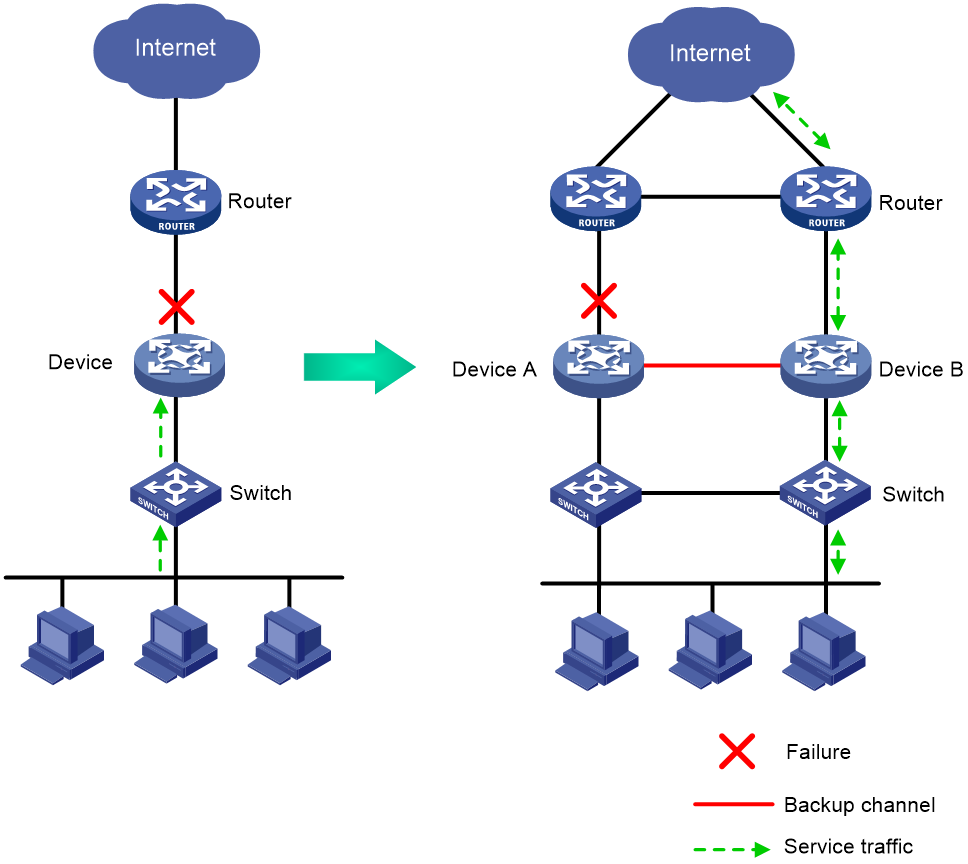
Application scenario
As shown in Figure 1, typically redundant egress devices are deployed at the border between the external and internal networks to prevent a single point of failure from interrupting traffic forwarding. When one egress device fails, traffic is switched to a different path.
Figure 1 HA group network model
Basic HA group concepts
Basic HA group concepts are as follows:
· Primary and secondary roles—In the control plane, the primary and secondary roles are assigned to the two devices in the HA group to control the configuration synchronization between the devices.
Each HA group member device adds a prefix to the view prompt to identify its HA role. The primary device adds the RBM_P prefix, RBM_P<Sysname> for example. The secondary device adds the RBM_S prefix, RBM_S<Sysname> for example.
· Active and standby states—Determine which device forwards and processes traffic in the data plane. The active device forwards traffic of services and backs up service entries to the standby device in real time. When the active device fails, the standby device takes over the active role to ensure service continuity.
· HA channels—Transmit status information, important configuration, and service entries between the HA group members.
· HA group modes—Include active/standby mode and dual-active mode. In active/standby mode, the active device processes all services. In dual-active mode, both devices process services to increase the capability of the HA group and load share traffic.
· HA packets—RBM packets transmitted through TCP over the HA channels between the HA group members.
Operating modes of the HA group
The HA group supports the active/standby and dual-active modes.
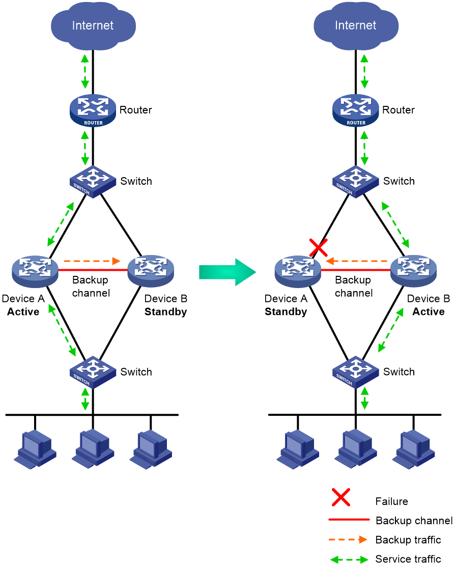
Active/standby mode
In active/standby mode, one device is active to process services, and the other device stands by, as shown in Figure 2. When an interface or link on the active device fails or when the active device fails, the standby device becomes active to process services.
Figure 2 Active/standby mode of the HA group
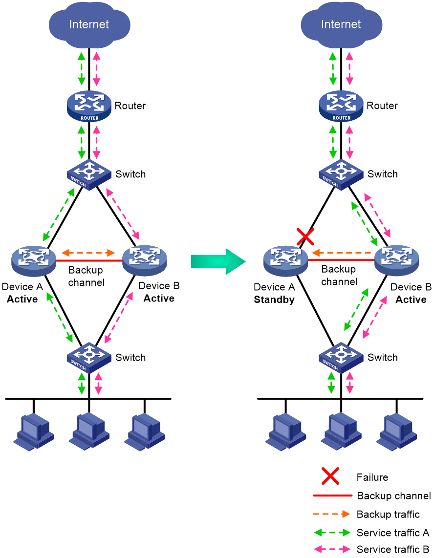
Dual-active mode
In dual-active mode, both devices process services to increase capability of the HA group, as shown in Figure 3. When one device fails, its traffic is switched to the other device for forwarding.
Figure 3 Dual-active mode of the HA group
HA data synchronization
HA packets
HA packets include the following:
· Keepalive packets—Transmitted periodically between the HA group members for peer availability detection.
· Control packets—Control active/standby switchovers based on the running status.
· Backup packets—Back up configuration and service entries between the HA group members.
· Configuration consistency check packets—Check whether the HA group members have consistent configuration.
· Transparent transmission packets—Transmit or replicate asymmetric-path traffic between the HA group members.
HA channels
The HA group transmits HA group status, important configuration, and service entries between the HA group members through the following channels:
· Control channel—Transmits data by using packets, including HA group status packets, configuration consistency check packets, and packets used for configuration synchronization.
· Data channel—Transmits backup packets and packets that require transparent transmission. The data channel uses the hardware driver for data transmission and supports only Layer 2 forwarding.
The control channel uses the keepalive mechanism of TCP for reachability detection. Each member device periodically sends HA keepalive packets to the HA peer over the HA control channel. If a device has not received any responses from the peer when the maximum number of HA keepalive attempts is reached, the HA control channel is disconnected.
Service entry backup
The HA group backs up the service entries generated on the active device to the standby device to prevent service interruption when an active/standby switchover occurs.
Security devices generate a session entry for each dynamic connection. In the HA group, only the active device processes traffic and generates session entries. To ensure service continuity, the active device backs up its session entries to the standby device in real time. After an active/standby switchover, the new active device can forward the packets of the existing services based on the session entries without interruption.
The HA group can perform hot backup for the following service entries:
· NAT port blocks.
· AFT port blocks.
· Session entries.
· Session relation entries.
· Entries generated by security service modules.
Configuration backup
The HA group backs up important configuration from the primary device to the secondary device to prevent service interruption when an active/standby switchover occurs.
· When both devices are operating correctly, the primary device synchronizes configuration to the secondary device. The configuration on the secondary device is overwritten. As a best practice to ensure correct operation of the HA group, enable configuration backup on the primary device.
· When one of the devices reboots, the device that completes reboot obtains configuration from the device that is not rebooted. The configuration on the rebooted device is overwritten.
The HA group supports both automatic backup and manual backup.
The HA group can perform configuration backup for the following services:
· Resources—VPN instance, ACL (excluding the acl copy command), object group, time range, security zone, session management, APR, and AAA (excluding the commands for local users and local guests).
· DPI—Application layer inspection engine, IPS, URL filter, data filter, file filter, anti-virus, data analysis center, and WAF.
· Polices—Security policy, ASPF, attack detection and prevention (excluding the blacklist ip command), connection limit, NAT, AFT, load balancing, bandwidth management, application auditing and management, shared network access management, and proxy policy.
· Logs—Fast log output (excluding the customlog host source command) and flow log (excluding the userlog flow export source-ip command).
· VPN—SSL VPN.
· Any other services—VLAN and cloud connection.
Configuration consistency check
The HA group verifies configuration consistency between the HA group members by using configuration consistency check packets. If a device detects configuration inconsistency, it generates a log for you to manually synchronize configuration.
Configuration consistency check operates as follows:
1. The primary device sends configuration consistency check packets to the secondary device and collects configuration digests of related modules at the same time.
2. The secondary device receives the packets, encapsulates its configuration digests into configuration consistency check packets, and sends these packets to the primary device.
3. The primary device compares its configuration digests with those of the secondary device. If inconsistency is detected, the primary device generates a log.
Running status switchover
The HA role is determined based on configuration. The running status is determined based on HA role election and can be switched over.
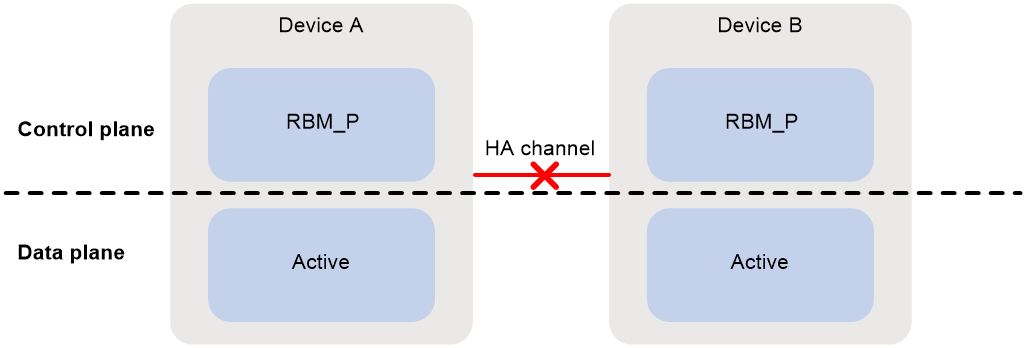
Running status switchover process
As shown in Figure 4, both devices are primary in the control plane and active in the data plane when the HA channels are not established. This is not a correct condition because the HA group has not set up.
Figure 4 HA channels not established
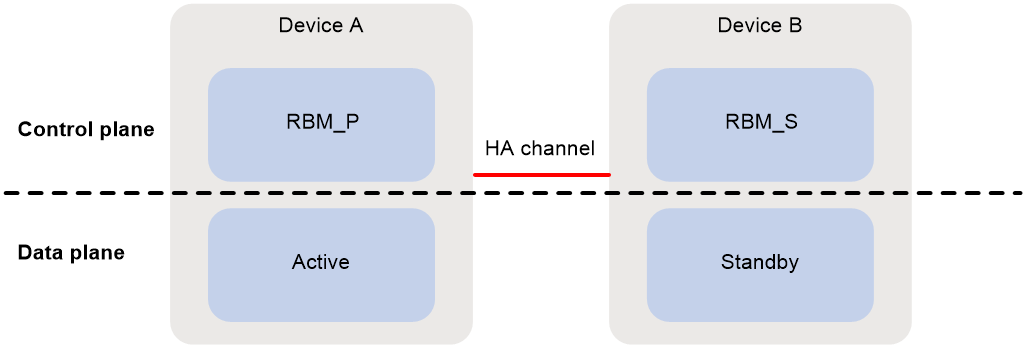
As shown Figure 5, when the HA channels are established and both devices are operating correctly, the HA roles of the devices are determined based on configuration and do not change in any condition. In the data plane, the running status of the devices is consistent with their HA roles. In active/standby mode, the primary device is the active device, and the secondary device is the standby device. In dual-active mode, both devices are active.
Figure 5 HA group in active/standby mode
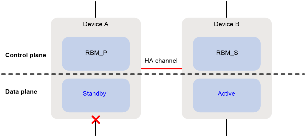
As shown in Figure 6, when the uplink or downlink fails on a device, the status of the devices changes in the data plane. The device that operates correctly processes all traffic. In the control plane, the HA roles of the devices do not change.
Figure 6 Uplink or downlink failure
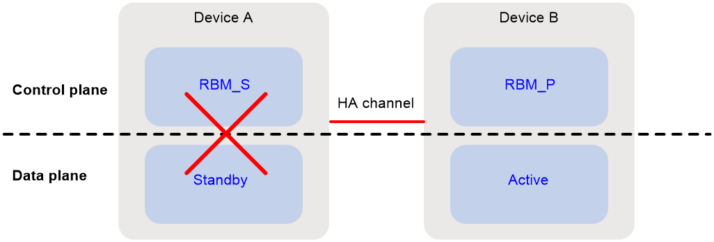
As shown in Figure 7, the HA role changes in the control plane only when the primary device fails or restarts, and the running status in the data plane will change accordingly. The secondary device will take over the primary role. When the original primary device recovers, it takes over the primary role.
Figure 7 Device failure or restart
Running status switchover triggers
In the HA group, an active/standby switchover occurs if one device fails or its links fail. The other device that operates correctly will take over to process all traffic that traverse the HA group to ensure service continuity. The following events can trigger an active/standby switchover.
· Disconnection of the HA control channel.
If the HA control channel is disconnected when both member devices are operating correctly, both devices become active devices. However, the devices will leave the HA group in this situation, and forwarding of asymmetric-path traffic will be interrupted.
· Failure of the active device.
· Failure of the interface monitored by the HA group on the active device.
· State change to Negative of any track entry monitored by the HA group on the active device.
This event triggers an active device election. If both member devices have track entries in Negative state, the following rules apply:
¡ In active/standby mode, the primary device is the active device, and the secondary device is the standby device.
¡ In dual-active mode, both member devices are active.
When an active/standby switchover occurs, the HA group collaborates with other modules to direct traffic to the new active device.
· When working with VRRP, the HA group places all VRRP groups on the failed device to backup state.
· When working with a routing protocol, the HA group increases the link costs of routes on the failed device.
Associating the HA group with VRRP
About HA group and VRRP association
You can use the HA group and VRRP in combination to control master/backup switchover for device role consistency (master or backup) in multiple VRRP groups. This ensures that both inbound and outbound traffic can be switched to the new master for symmetric forwarding upon device failure.
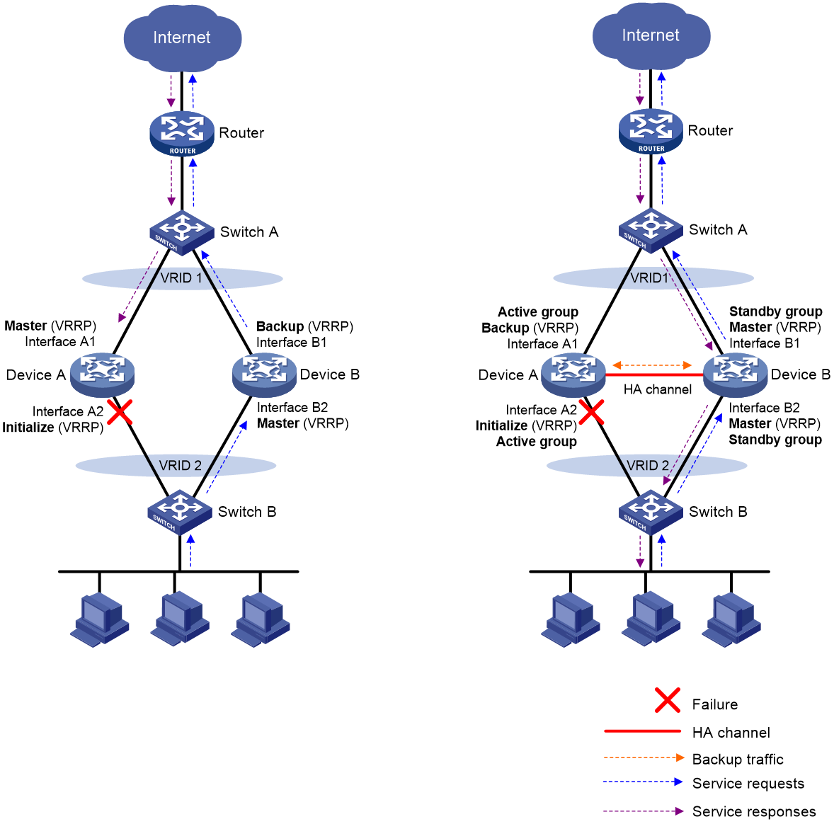
Figure 8 illustrates VRRP association with the HA group in active/standby mode.
· As shown in the left, VRRP cannot ensure symmetric forwarding upon failure on a device, which causes traffic interruption.
· As shown in the right, after the HA control channel is established, the HA group determines the roles of the devices in all VRRP groups. The master election mechanism of VRRP no longer takes effect. If the HA control channel is disconnected, the master election mechanism of VRRP takes effect again.
Figure 8 VRRP and HA group association
VRRP active/standby group
The HA group is associated with VRRP by VRRP active and standby groups.
A VRRP active/standby group can be in master or backup state, which determines the state of devices in the associated VRRP groups. For example, if a VRRP active group is in master state, all devices in the associated VRRP groups are masters.
The initial state of a VRRP active/standby group is depends on the HA group mode.
· Active/Standby mode—On the primary device, the initial state is master for the VRRP active and standby groups. On the secondary device, the initial state is backup for the VRRP active and standby groups.
· Dual-active mode—The state of a VRRP active/standby group is not affected by the HA roles. The initial state is master for the VRRP active group and is backup for the VRRP standby group.
VRRP master election in the HA group environment
After the HA group is associated with VRRP, the HA group determines the roles of the devices in the VRRP groups. As shown in Figure 8, Device A is the master in VRRP group 1 and VRRP group 2, and Device B is the backup in VRRP group 1 and VRRP group 2. When Interface A2 on Device A fails, the following events occur:
1. The HA group receives an interface failure event and sends the status change information of the VRRP active and standby groups to Device B.
2. Device B sets its role to master in the VRRP standby group and then becomes the master in VRRP group 1 and VRRP group 2.
3. Device B sends a response to Device A after the master/backup switchover.
4. Device A sets its role to backup in the VRRP active group and then becomes the backup in VRRP group 1 and VRRP group 2.
When Interface A2 recovers, the HA group performs another master/backup switchover following the same procedure. Traffic is switched back to Device A after the switchover.
ARP and MAC learning in VRRP
When the members of a VRRP group receive an ARP request for the group's virtual IP address, the master replies with the group's virtual MAC address. This allows the upstream and downstream Layer 2 devices and hosts to learn the virtual MAC address.
Associating the HA group with routing protocols
You can use the HA group to enable the routing protocols on the standby device to advertise modified link cost. The feature ensures that both inbound and outbound traffic can be switched to the new active device for symmetric forwarding.
This feature requires associating the HA group with Track to perform active/standby switchover upon link or interface failures.
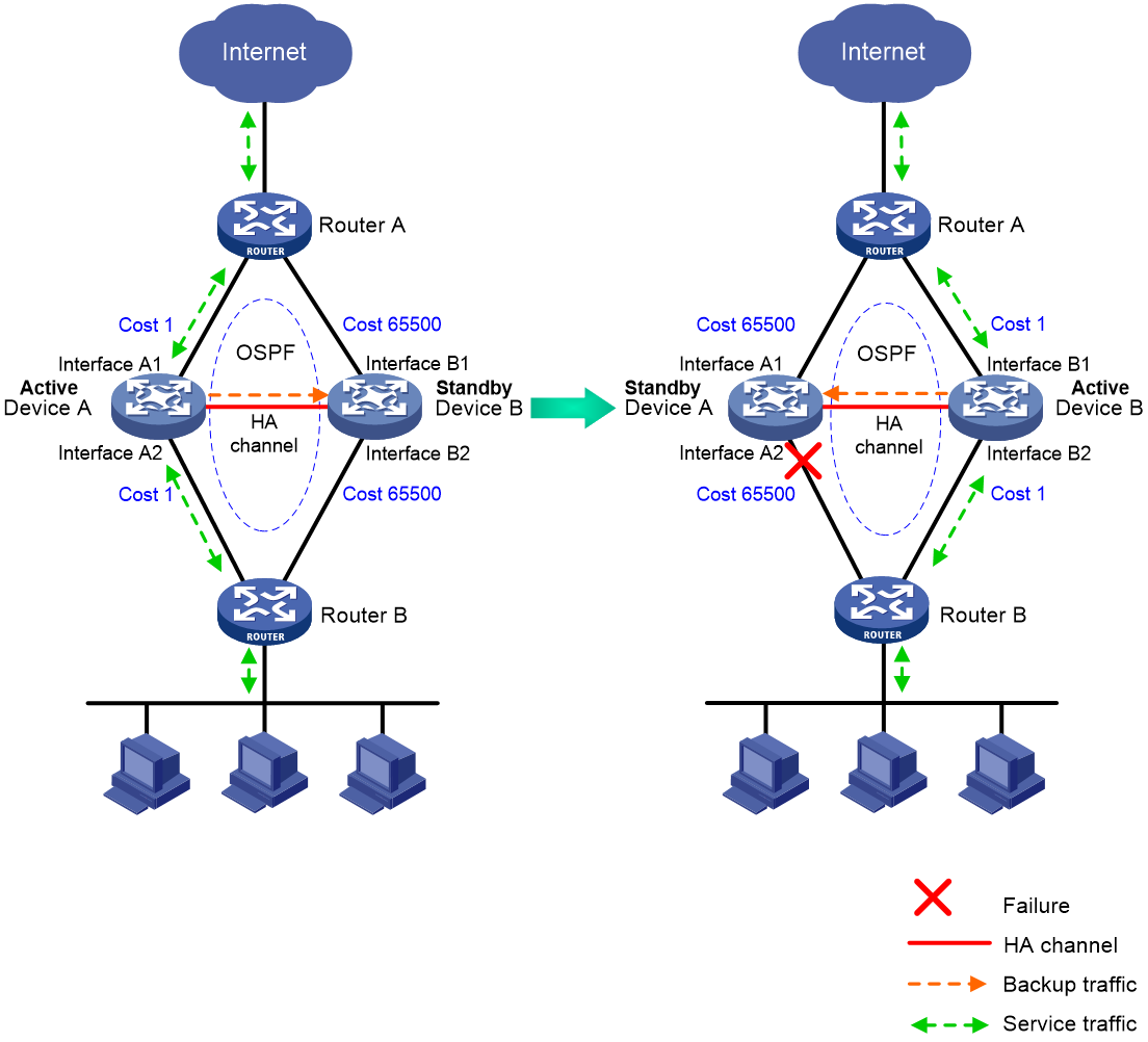
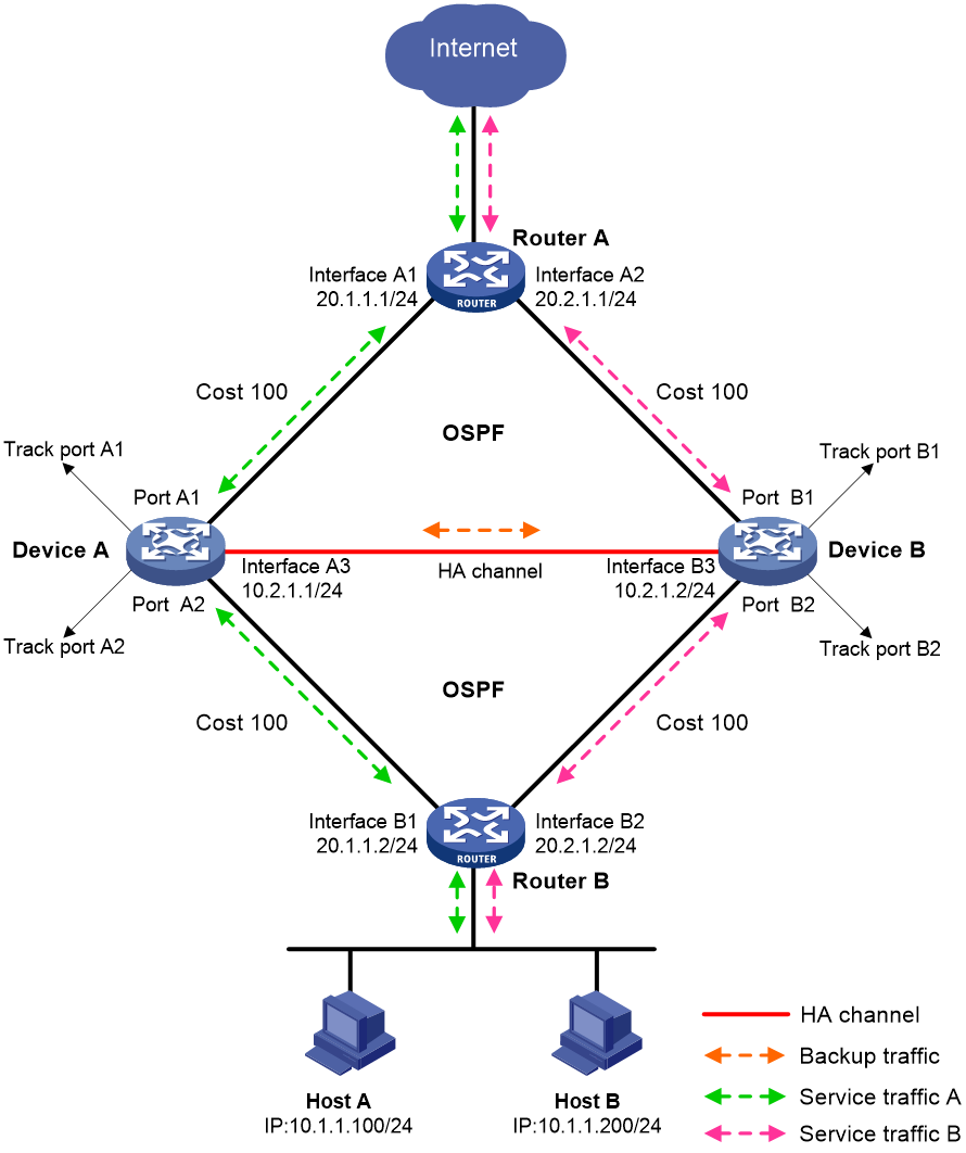
Figure 9 illustrates OSPF association with the HA group in active/standby mode.
· As shown in the left, Device A (active device) advertises link cost 1 based on OSPF configuration. Device B (standby device) advertises link cost 65500 modified by the HA group. Both inbound and outbound traffic are forwarded through Device A.
· As shown in the right, when interface A2 fails, Device A and Device B perform an active/standby switchover. After the switchover is complete, Device B (active device) advertises link cost 1 based on OSPF configuration. Device A (standby device) advertises link cost 65500 modified by the HA group. Both inbound and outbound traffic are forwarded through Device B.
Figure 9 OSPF and HA group association
Transparent in-path deployment of the HA group
When you use this networking scheme, you can use the track vlan or track interface command to enable collaboration between uplink and downlink interfaces. The Track configuration ensures that a group of interfaces have the same status, and uplink and downlink traffic can be switched simultaneously between the member devices.
The following information uses the track vlan setting as an example to describe how interfaces collaborate:
· As shown in Figure 10, when both Device A (active) and Device B (standby) are operating correctly, tracked VLAN 10 is in active state on Device A and in inactive state on Device B. As a result, Device A forwards all traffic that traverses the HA group.
· As shown in Figure 10, when downlink Port A2 of Device A fails, Device A and Device B switch their roles. Then, the HA group places VLAN 10 in inactive state on Device A (standby) and in active state on Device B (active). As a result, Device B forwards all traffic that traverses the HA group.
Figure 10 Transparent in-path deployment of the HA group

Restrictions: Hardware compatibility with the HA group
|
F1000 series |
Models |
HA group compatibility |
|
F1000-X-G5 series |
F1000-A-G5, F1000-C-G5, F1000-C-G5-LI, F1000-E-G5, F1000-H-G5, F1000-S-G5 |
Yes |
|
F1000-X-G3 series |
F1000-A-G3, F1000-C-G3, F1000-E-G3, F1000-S-G3 |
Yes |
|
F1000-X-G2 series |
F1000-A-G2, F1000-C-G2, F1000-E-G2, F1000-S-G2 |
Yes |
|
F1000-9X0-AI series |
F1000-9390-AI, F1000-9385-AI, F1000-9380-AI, F1000-9370-AI, F1000-9360-AI, F1000-9350-AI, F1000-9330-AI, F1000-9320-AI, F1000-990-AI, F1000-980-AI, F1000-970-AI, F1000-960-AI, F1000-950-AI, F1000-930-AI, F1000-920-AI , F1000-910-AI, F1000-905-AI |
Yes |
|
F1000-C83X0 series |
F1000-C8395, F1000-C8390, F1000-C8385, F1000-C8380, F1000-C8370, F1000-C8360, F1000-C8350, F1000-C8330 |
Yes |
|
F1000-C81X0 series |
F1000-C8180, F1000-C8170, F1000-C8160, F1000-C8150, F1000-C8130, F1000-C8120, F1000-C8110 |
Yes |
|
F1000-7X0-HI series |
F1000-770-HI, F1000-750-HI, F1000-740-HI, F1000-730-HI, F1000-720-HI, F1000-710-HI |
Yes |
|
F1000-C-X series |
F1000-C-EI, F1000-C-HI, F1000-C-XI, F1000-E-XI |
Yes |
|
F1000-V series |
F1000-E-VG, F1000-S-VG |
Yes |
|
SecBlade IV |
LSPM6FWD8, LSQM2FWDSC8 |
Yes |
|
F100 series |
Models |
HA group compatibility |
|
F100-X-G5 series |
F100-A-G5, F100-C-G5, F100-E-G5, F100-M-G5, F100-S-G5 |
Yes |
|
F100-X-G3 series |
F100-A-G3, F100-C-G3, F100-E-G3, F100-M-G3, F100-S-G3 |
Yes |
|
F100-X-G2 series |
F100-A-G2, F100-C-G2, F100-E-G2, F100-M-G2, F100-S-G2 |
Yes |
|
F100-WiNet series |
F100-A80-WiNet, F100-C80-WiNet, F100-C60-WiNet, F100-S80-WiNet, F100-A81-WiNet, F100-A91-WiNet, F100-C50-WiNet |
Yes |
|
F100-C-A series |
F100-C-A6, F100-C-A5, F100-C-A3 |
Yes |
|
F100-C-A6-WL, F100-C-A5-W, F100-C-A3-W |
No |
|
|
F100-X-XI series |
F100-A-EI, F100-A-HI, F100-A-SI, F100-C-EI, F100-C-HI, F100-C-XI, F100-E-EI, F100-S-HI, F100-S-XI |
Yes |
Restrictions and guidelines: HA group configuration
Member device restrictions and guidelines
The HA group can contain a maximum of two devices.
To ensure that the traffic size is within the processing capability of one device upon failure of the other device, make sure the throughput of each device does not exceed 50% of its capability.
Configuration synchronization restrictions and guidelines
For the service modules for which HA supports configuration synchronization, you need to configure relevant settings only on the primary device. For the service modules that do not support configuration synchronization, you need to configure relevant settings on all devices in the HA group. For support of HA for configuration synchronization of service modules, see "Configuration backup."
For resource file associated functions or files (such as public key information, ISP address library file, and signature file), you need import the file with the same content to all devices in the HA group.
For the features or signature libraries that require licenses, purchase separate licenses and activate them on the HA group member devices.
Interface restrictions and guidelines
On each member device, you must assign all interfaces that transmit service traffic to security zones and configure security policies to enable inter-zone communication.
Do not use the HA group in combination with the features that obtain IP addresses automatically, DHCP client for example. The interfaces on the HA group must use static IP addresses.
If service interfaces work in Layer 2 mode, assign uplink and downlink service interfaces to the same VLAN.
HA channel restrictions and guidelines
The HA channels are set up over the keepalive link that is a direct link or traverses only Layer 2 switches.
When you select interfaces for HA channel setup, follow these restrictions and guidelines:
· Use physical interfaces or aggregate interfaces. Do not use subinterfaces or aggregation member ports.
· As a best practice, use the same physical or logical link to convey the HA data and control channels. Use the default MTU on the interfaces used for setting up the link.
When configuration backup is in progress, do not perform active/standby switchovers, remove or install service modules, or change the configuration. To view the backup progress, execute the display remote-backup-group status command.
If the HA group performs asymmetric forwarding, use the session aging-time state fin command to set the aging time for TCP sessions in FIN_WAIT state to 15 seconds. This configuration speeds up session entry aging when TCP connections disconnect and thus saves system resources. For more information about the session aging-time state command, see session management commands in Security Command Reference.
HA group deployment restrictions and guidelines
When you deploy the HA group, follow the restrictions and guidelines for the network scheme you have chosen.
Routed in-path HA group deployment between upstream and downstream routers
You can use either active/standby or dual-active mode.
If you use the HA group with a routing protocol, use the adjust-cost enable command to enable the HA group to adjust the link costs for the routing protocol. In addition, associate the HA group with track entries to monitor the status of uplink and downlink interfaces.
If you use the HA group with static routes, use the track interface command to monitor uplink and downlink Layer 3 Ethernet interfaces.
Routed in-path HA group deployment between upstream and downstream switches
You can use either active/standby or dual-active mode.
You must use the HA group with VRRP and configure the HA group to work with track entries to monitor the status of uplink and downlink interfaces.
Transparent in-path HA group deployment between upstream and downstream routers
You can use either active/standby or dual-active mode.
You must use the track interface command to enable the HA group to monitor the status of uplink and downlink Layer 2 Ethernet interfaces.
Transparent in-path HA group deployment between upstream and downstream switches
You can use only active/standby mode.
You must use the track vlan command to enable the HA group to monitor the status of uplink and downlink VLANs.
Feature compatibility restrictions
Compatibility with contexts
You can configure the HA group only on the default context. The configuration will be issued to all non-default contexts.
When an active/standby switchover occurs on any context, the other contexts will perform an active/standby switchover accordingly. As a best practice, place the active member devices of all contexts on the same device.
If you use the HA group feature on a non-default context, you must assign service interfaces to the non-default context in shared mode.
Compatibility with NAT
When you use NAT on the HA group, follow these restrictions:
· The HA group does not support detecting reachability of NAT address group members or Easy IP.
· NAT address groups cannot contain the IP addresses of any interfaces on the HA group member devices. If you violate this restriction, both HA group member devices will respond to the ARP packets that an upstream device sends to request the IP addresses in the NAT address groups. As a result, ARP conflicts occur.
· The source or destination IP address in a NAT policy does not belong to the interface used for setting up the HA channels. Violation of this restriction causes keepalive link faults.
· If you cannot ensure that a flow identified by a five-tuple is processed by the same device in one direction, you must use the nat remote-backup port-alloc { primary | secondary } command to specify NAT port ranges for both HA group member devices.
When you use NAT on the HA group operating in dual-active mode, follow these restrictions:
· NAT address groups do not support EIM.
· If NAT operates in PAT mode, you must execute the following commands on the NAT group members, one command on one device:
¡ nat remote-backup port-alloc primary
¡ nat remote-backup port-alloc secondary
These commands divide an address group into two halves to avoid conflicts.
· If NAT operates in NO-PAT mode, you must configure two address groups to avoid resource assignment conflicts.
Compatibility with other protocols
Make sure the control and data packets of a multi-channel protocol such as FTP or SIP are processed by the same HA group member device.
In the HA environment, to process traffic based on the SCTP protocol, make sure both the outbound and inbound packets of the same flow are processed by the same device.
Hardware environment consistency
Before you configure the HA group, verify that the following hardware settings are the same on the devices to be assigned to the HA group:
· Device model.
· Number and type of management interfaces, service interfaces, and interfaces for setting up the HA channels. Do not use one interface for multiple purposes.
· Location, number, and type of disks. A device not with disks installed has small log storage and do not support some types of logs or reports.
Software environment consistency
Before you configure the HA group, verify that the following software settings are the same on the devices to be assigned to the HA group:
· Software environment and version, including boot packages, system packages, feature packages, and patches.
· Licensed signature libraries and features, such as signature library types, signature library version, validation time, and number of licensed resources.
· Interface numbers.
· Type, speed, and number of the interfaces for setting up the HA channels. As a best practice, use aggregate interfaces.
· Aggregate interface numbers and aggregation member port numbers.
· Security zone configuration on the interfaces at the same location.
· Multi-CPU packet distribution policy (configurable with the forwarding policy command).
Network interconnection restrictions
Configure security policies for the HA group members to correctly exchange the packets required in forwarding over the HA channels, routing protocol packets for example. As a best practice, make sure only those packets are transmitted between the security zone that accommodates service interfaces and the Local security zone.
The device by default permits the HA packets transmitted over the HA channels. You do not need to configure security policies for the HA packets.
Configure a feature prior to HA group deployment if the HA group cannot back up configuration of the feature. For more information about the features that can be backed up by the HA group, see "Configuration backup."
HA group configuration flow
Figure 11 shows the configuration flow for the HA group.
Figure 11 HA group configuration flow chart
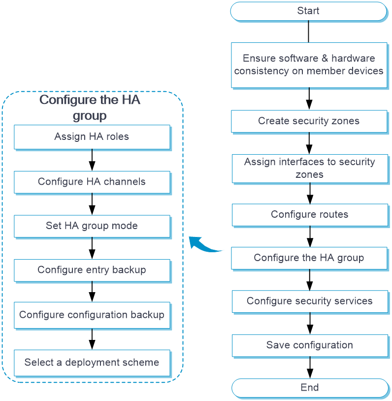
HA group tasks at a glance
To configure the HA group, perform the following tasks:
2. Configuring HA data synchronization settings
a. Configuring the HA control channel
b. Configuring the HA data channel
c. Enabling service entry hot backup
d. Configuring HA configuration synchronization
3. Enabling traffic switchover upon failure recovery
4. Setting the HA group mode
Choose one of the following tasks:
¡ Configuring the active/standby mode
¡ Configuring the dual-active mode
5. Configuring HA group associations
Choose one of the following tasks:
¡ Associating the HA group with VRRP
¡ Associating the HA group with routing protocols
¡ Configuring HA group transparent in-path deployment
6. (Optional.) Associating the HA group with Track
7. (Optional.) Performing an active/standby switchover
8. (Optional.) Enabling transparent service traffic transmission between the HA group members
9. (Optional.) Configuring service features on the HA group
Configuring the HA role
About this task
The HA group backs up important configuration from the primary device to the secondary device to prevent service interruption when an active/standby switchover occurs. The configuration on the secondary device is overwritten. The unidirectional backup mechanism avoids configuration conflicts, especially in dual-active mode. The HA roles can only be manually assigned to devices.
Each HA group member device adds a prefix to the view prompt to identify its HA role.
· The primary device adds the RBM_P prefix, RBM_P<Sysname> for example.
· The secondary device adds the RBM_S prefix, RBM_S<Sysname> for example.
After you assign HA roles to the HA group member devices, both devices add the RBM_P prefix to their view prompts. The devices display view prompt prefixes according to their HA roles after they set up the HA control channel.
Restrictions and guidelines
You must assign the primary and secondary roles to the two member devices in the HA group, respectively.
As a best practice to ensure correct operation of the HA group, enable configuration backup on the primary device.
Procedure
1. Enter system view.
system-view
2. Enter HA group view.
remote-backup group
3. Configure the HA role.
device-role { primary | secondary }
By default, the HA role is not configured.
Configuring the HA control channel
About this task
The HA group compares the specified local and peer IP address to determine the device role for setting up the control channel. The device with higher IP address acts as the server, and the other device acts as the client to initiate the TCP connection.
If the port number is configured on the server, the port provides services for the client. If the port number is configured on the client, the port serves as the destination port to establish TCP connection to the server. The source port is randomly generated on the client.
Restrictions and guidelines
You can specify only one peer IP address with the same port number on the HA group member devices. The specified port cannot be the same as the TCP listening port in use.
The local and peer IP addresses used for setting up the control channel cannot be identical.
You can set up an IPv4 control channel or IPv6 control channel, but not both.
Procedure
1. Enter system view.
system-view
2. Enter HA group view.
remote-backup group
3. Set up an HA control channel. Choose one of the following options:
¡ Set up an IPv4 control channel.
- Configure the peer IPv4 address for setting up the HA control channel.
remote-ip ipv4-address [ port port-number ]
By default, the peer IPv4 address is not configured.
- Configure the local IPv4 address for setting up the HA control channel.
local-ip ipv4-address
By default, the local IPv4 address is not configured.
¡ Set up an IPv6 control channel.
- Configure the peer IPv6 address for setting up the HA control channel.
remote-ipv6 ipv6-address [ port port-number ]
By default, the peer IPv6 address is not configured.
- Configure the local IPv6 address for setting up the HA control channel.
local-ipv6 ipv6-address
By default, the local IPv6 address is not configured.
4. Set the interval for sending HA keepalive packets.
keepalive interval interval
By default, the device sends HA keepalive packets at one-second intervals.
5. Set the maximum number of HA keepalive attempts.
keepalive count counts
By default, the maximum number of HA keepalive attempts is 10.
Configuring the HA data channel
1. Enter system view.
system-view
2. Enter HA group view.
remote-backup group
3. Configure an HA data channel.
data-channel interface interface-type interface-number
By default, no HA data channel is configured.
Enabling service entry hot backup
About this task
Service entry hot backup enables the active device to back up service entries to the standby device in real time.
Enable HTTP and DNS backup if asymmetric-path traffic traverses the HA group. HTTP and DNS backup ensures that a flow and its return traffic are processed correctly on the HA group members.
If HA active/standby mode is used or only symmetric-path traffic traverses the HA group, disabling HTTP and DNS backup can improve performance of the HA group members at the expense of delayed data synchronization. When you disable HTTP and DNS backup, make sure you are fully aware of the impact on the network. A device removes a DNS or HTTP connection if packet exchange is inactive. When a switchover interrupts a connection, the DNS or HTTP client re-initiates the connection immediately, which has little impact on user services.
Restrictions and guidelines
When the HA group is operating stably and is processing traffic, do not execute the reset session table command. If you execute the command, traffic might be interrupted, and the session entries might become inconsistent on the primary and backup devices. For more information about session management, see Security Configuration Guide.
Procedure
1. Enter system view.
system-view
2. Enter HA group view.
remote-backup group
3. Enable service entry hot backup.
hot-backup enable
By default, service entry hot backup is enabled.
4. Enable hot backup for the session entries of application layer protocols.
hot-backup protocol { dns | http } * enable
By default, the HA group performs hot backup for the session entries of application layer protocols.
The hot-backup protocol enable command takes effect only on DNS and HTTP. The device automatically backs up the session entries of other application layer protocols after you enable service entry hot backup.
Configuring HA configuration synchronization
About this task
The HA group member devices can synchronize configuration changes in real time and synchronize all configuration in bulk.
· Real-time synchronization—The primary device copies added, deleted, or modified configuration to the secondary device in real time to maintain configuration consistency.
· Bulk synchronization—The primary device backs up important configuration in bulk to the secondary device. The secondary device will delete the settings that are inconsistent with those on the primary device.
The HA group can perform HA configuration synchronization only when automatic configuration synchronization is enabled and the HA control channel is set up.
A bulk synchronization is triggered by the following events:
· The HA control channel is set up and automatic configuration synchronization is enabled (including the default status) for the first time. The primary device will send all its key configuration in bulk to overwrite the configuration on the secondary device. The HA group does not perform bulk synchronization afterwards, even if automatic configuration synchronization is enabled again or the HA control channel is set up again.
· An HA group member device reboots, or the HA process restarts, and automatic configuration synchronization is enabled on the other device. After the reboot or restart and the HA control channel is set up again, the device that does not reboot will send all its key configuration in bulk to overwrite the configuration on the rebooted device.
Restrictions and guidelines
After the HA control channel is set up and automatic configuration synchronization is enabled for the first time, do not disable automatic configuration synchronization. If you fail to do so, the devices will not perform bulk configuration, and configuration inconsistency will affect services.
If the amount of configuration to be synchronized is large, bulk synchronization might take one to two hours. To avoid the issue, you can perform one of the following operations:
· Enable automatic configuration synchronization first when you configure the HA group.
· Copy the configuration file to the secondary device during initial network deployment and then enable configuration consistency check.
Procedure
1. Enter system view.
system-view
2. Enter HA group view.
remote-backup group
3. Enable automatic configuration synchronization.
configuration auto-sync enable
By default, automatic configuration synchronization is enabled.
4. Enable configuration consistency check.
configuration sync-check [ interval interval ]
By default, configuration consistency check is enabled.
5. (Optional.) Perform a one-off configuration consistency check.
configuration manual-sync-check
This command applies only to the primary device.
6. (Optional.) Manually synchronize the configuration of the primary device to the secondary device.
configuration manual-sync
This command applies only to the primary device.
Enabling traffic switchover upon failure recovery
About this task
After an active/standby switchover occurs, if the original active device recovers, traffic will not be switched back by default. Perform this task to enable traffic switchover to the original active device upon failure recovery. You can set a delay timer to ensure smooth service switchover.
Restrictions and guidelines
In dual-active mode, you must enable this feature to ensure that both devices can operate after the failure is recovered.
This feature does not take effect on ongoing traffic switchovers. It applies only to subsequent traffic switchovers.
Procedure
1. Enter system view.
system-view
2. Enter HA group view.
remote-backup group
3. Enable traffic switchover upon failure recovery.
delay-time delay-time
By default, traffic switchover upon failure recovery is disabled.
Configuring the active/standby mode
1. Enter system view.
system-view
2. Enter HA group view.
remote-backup group
3. Configure the active/standby mode.
undo backup-mode dual-active
By default, the HA group mode is active/standby.
Configuring the dual-active mode
1. Enter system view.
system-view
2. Enter HA group view.
remote-backup group
3. Configure the dual-active mode.
backup-mode dual-active
By default, the HA group mode is active/standby.
Associating the HA group with VRRP
Restrictions and guidelines
You can associate only VRRP groups operating in standard mode with the HA group.
Use the HA group in combination with VRRP groups only for in-path HA group deployment between upstream and downstream switches. As a best practice, assign the primary device to the VRRP active group, and assign the secondary device to the VRRP standby group.
You can assign multiple virtual IP addresses to a VRRP group associated with the HA group. Make sure the interfaces in the VRRP group do not own the virtual IP addresses.
You cannot associate a VRRP group with both the HA group and Track.
For an IPv6 VRRP group to work correctly, you must assign it a link-local address and a global unicast address as virtual IPv6 addresses.
Procedure
1. Enter system view.
system-view
2. Enter interface view.
interface interface-type interface-number
3. Associate the HA group with VRRP. Choose one of the following options:
¡ Create an IPv4 VRRP group and associate it with the HA group.
vrrp vrid virtual-router-id virtual-ip virtual-address [ mask | mask-length ] { active | standby }
By default, no IPv4 VRRP groups exist.
¡ Create an IPv6 VRRP group and associate it with the HA group. Assign a link-local address and a global unicast address as virtual IPv6 addresses to the VRRP group.
vrrp ipv6 vrid virtual-router-id virtual-ip virtual-address [ prefix-length ] link-local { active | standby }
vrrp ipv6 vrid virtual-router-id virtual-ip virtual-address
By default, no IPv6 VRRP groups exist.
Associating the HA group with routing protocols
Enabling the HA group to adjust the link cost for a routing protocol
About this task
When you use the HA group together with a routing protocol, you can enable the HA group to adjust the link cost for a routing protocol on the standby device. This feature applies to the scenario where the HA group member devices run the same routing protocol. If you configure this feature, the active device advertises the original link costs for a routing protocol, and the standby device advertises one of the following link costs:
· Absolute cost—The device advertises an absolute link cost for the routing protocol.
· Calculated cost—The device advertises the original link cost plus the configured increment cost for the specified routing protocol.
The feature takes effect on only the standby device.
Restrictions and guidelines
This feature applies to the scenario where the HA group member devices run the same routing protocol.
To ensure switchover of both uplink and downlink traffic to the new active device, configure this feature with the same parameters on both HA group member devices.
Do not use the silent-backup-interface and adjust-cost enable commands together.
In the HA group in dual-active mode in collaboration with a routing protocol, as a best practice, configure per-flow load sharing for IP forwarding on both the uplink and downlink devices.
Procedure
1. Enter system view.
system-view
2. Enter HA group view.
remote-backup group
3. Enable the HA group to adjust the link cost for the specified routing protocol on the standby device.
adjust-cost { bgp | isis | ospf | ospfv3 } enable { absolute [ absolute-cost ] | increment [ increment-cost ] }
By default, the HA group does not adjust the link cost for the specified routing protocol on the standby device.
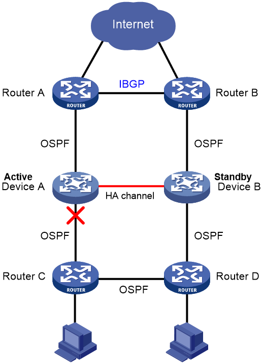
Disabling the standby device from sending or receiving protocol packets of a routing protocol.
This feature applies to the scenario where the HA group member devices run multiple routing protocols. As shown in Figure 12, IBGP and OSPF have different default priorities. When the link between Device A and Router C fails, traffic destined for the hosts might be forwarded to Device A as OSPF has higher priority than IBGP. To resolve this issue, disable Device A from sending or receiving OSPF protocol packets to disconnect its OSPF neighbors. Then, Device B will forward all uplink and downlink traffic.
Figure 12 HA group member devices running multiple routing protocols
Restrictions and guidelines
This feature applies to the scenario where the HA group member devices run multiple routing protocols.
To ensure switchover of both uplink and downlink traffic to the new active device, configure this feature with the same parameters on both HA group member devices.
Do not use the silent-backup-interface and adjust-cost enable commands together.
Procedure
1. Enter system view.
system-view
2. Enter HA group view.
remote-backup group
3. Disable the standby device from sending or receiving protocol packets of a dynamic routing protocol.
silent-backup-interface { ospf | ospfv3 }
By default, the standby device can send and receive protocol packets of a dynamic routing protocol.
Configuring HA group transparent in-path deployment
Enabling the HA group to monitor interfaces
About this task
Perform this task to enable the HA group to monitor the interfaces connecting the uplink and downlink devices in HA group transparent in-path deployment. The monitored interfaces can forward packets only when they are all up. If any of the monitored interfaces goes down, none of them will be able to forward packets.
Restrictions and guidelines
You can use the track interface and track commands in conjunction, but you cannot use these commands to monitor the same interfaces.
The track vlan and track interface commands are mutually exclusive. You cannot configure both of them.
The HA group does not support monitoring member ports of aggregate interfaces.
Procedure
1. Enter system view.
system-view
2. Enter HA group view.
remote-backup group
3. Enable the HA group to monitor a Layer 2 or Layer 3 Ethernet interface.
track interface interface-type interface-number
By default, the HA group does not monitor any interfaces.
Enabling the HA group to monitor VLANs
About this task
Perform this task to enable the HA group to monitor the VLANs of the uplink and downlink devices in HA group transparent in-path deployment. The monitored VLANs are active and the member ports can forward packets only when the member ports are all up. If any of the member ports goes down, none of them will be able to forward packets, and all the monitored VLANs will become inactive.
In active/standby mode, the state of monitored VLANs is active on the primary device and inactive on the secondary device.
In dual-active mode, the state of monitored VLANs is active on both the primary and secondary devices.
Restrictions and guidelines
The track vlan command is mutually exclusive with the track interface and track commands. You cannot use the track vlan command in conjunction with the track interface or track command.
Do not enable the HA group to monitor VLAN 1 (to which all access ports belong by default). This restriction prevents an unused interface in down state from interrupting operation of other interfaces in VLAN 1.
Procedure
1. Enter system view.
system-view
2. Enter HA group view.
remote-backup group
3. Enable the HA group to monitor a VLAN.
track vlan vlan-id
By default, the HA group does not monitor any VLANs.
Associating the HA group with Track
About this task
Perform this task to associate the HA group with Track to monitor links. If one of the monitored track entries becomes Negative, the HA group performs an active/standby switchover and switches traffic to the new active device to ensure service continuity. For more information about Track, see Network Management and Monitoring Configuration Guide.
Procedure
1. Enter system view.
system-view
2. Enter HA group view.
remote-backup group
3. Associate the HA group with Track.
track track-entry-number
By default, the HA group is not associated with Track.
Performing an active/standby switchover
About this task
If you want to replace components or upgrade software on the current active device, you can perform this task to switch services to the standby device.
Restrictions and guidelines
This feature applies only when the HA group operates in active/standby mode, and it takes effect on only the active device.
In an HA group and VRRP associated network, performing this task might cause temporary virtual IP address conflict in the VRRP group, which is considered a normal condition.
For stable operation of the HA group, do not repeatedly perform this task within one minute.
Procedure
1. Enter system view.
system-view
2. Enter HA group view.
remote-backup group
3. Perform an active/standby switchover.
switchover request
Enabling transparent service traffic transmission between the HA group members
About this task
Enable transparent service traffic transmission only when asymmetric-path traffic traverses the HA group operating in dual-active mode.
If an asymmetric-path flow traverses the HA group operating in dual-active mode, the flow and its return traffic are processed by different HA group members. This will degrade the traffic processing performance of modules such as NBAR, DPI, and load balancing. For example, the packet recognition rate of NBAR might drop. For an asymmetric-path flow and its return traffic to be processed by the same HA group member, enable transparent service traffic transmission. Transparent service traffic transmission is resource-intensive. Make sure you are fully aware of the impact of this feature when you use it on a live network.
Procedure
1. Enter system view.
system-view
2. Enter HA group view.
remote-backup group
3. Enable transparent service traffic transmission between the HA group members.
transparent-transmit enable
By default, transparent service traffic transmission is enabled.
Configuring service features on the HA group
NAT on the HA group
For NAT to operate correctly on the HA group, you must associate NAT features with the VRRP groups. For example, when you use dynamic NAT, static NAT, NAT server, or NAT444, you must associate the feature with the VRRP groups. For more information about NAT features, see NAT Configuration Guide.
NAT features have similar mechanisms, and the operating mode of the HA group does not change the IP address translation process. This section uses dynamic NAT on the HA group in active/standby mode to explain how NAT works on the HA group.
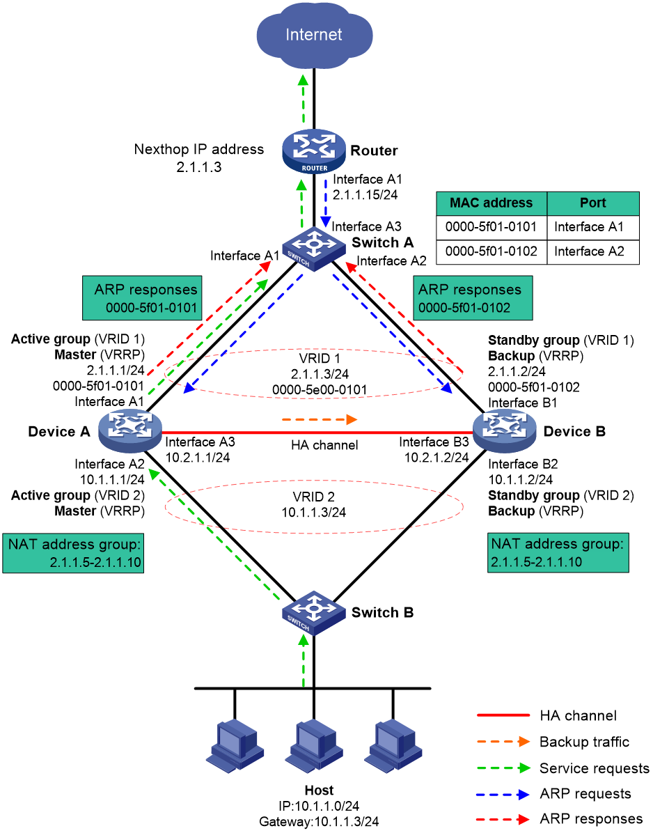
About NAT on the HA group
When receiving an ARP request with a target IP address that belongs to the subnet of the IP address of a NAT interface, a NAT device replies with the MAC address of the NAT interface.
As shown in Figure 13, dynamic NAT is configured on the HA group that is operating in active/standby mode. If dynamic NAT is not associated with any VRRP group, the devices process the traffic as follows when the host accesses the Internet:
1. When receiving the packets sent by the host, Device A translates the source IP address into a public IP address in the NAT address group and forwards the packets to the router. In this example, the public IP address is in the same subnet as the virtual IP address of uplink VRRP group 1.
2. The router receives the return packets and broadcasts an ARP request for the destination public IP address.
3. Device A and Device B receive the ARP request and reply with the MAC address of their respective uplink interface because they have the same NAT address group configuration.
4. The router might send the return packets to the uplink interface of Device A or Device B, which affects service continuity.
For the router to learn the virtual MAC address of the uplink VRRP group, you must associate NAT features with the VRRP group.
Figure 13 NAT not associated with a VRRP group
Traffic forwarding process
The master in a VRRP group relies with the virtual MAC address of the VRRP group to an ARP request if the following requirements are met:
· NAT features are associated with the VRRP group.
· The target IP address belongs to the subnet that contains the IP address of a NAT interface.
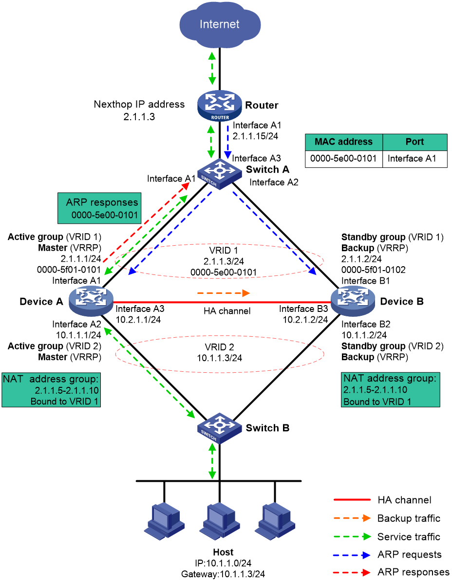
As shown in Figure 14, dynamic NAT is configured on the HA group that is operating in active/standby mode. If NAT is associated with the uplink VRRP group, the devices process the traffic as follows when the host accesses the Internet:
1. When receiving the packets sent by the host, Device A translates the source IP address into a public IP address in the NAT address group and forwards the packets to the router. In this example, the public IP address is in the same subnet as the virtual IP address of uplink VRRP group 1.
2. The router receives the return packets and broadcasts an ARP request for the destination public IP address.
3. Device A and Device B receive the ARP request, and Device A (master) replies with the virtual MAC addresses of the uplink VRRP group.
4. Router A sends the return packets to Device A.
Figure 14 NAT on the HA group
For more information about VRRP group association with dynamic NAT, static NAT, NAT server, and NAT444, see Layer 3—IP Services Configuration Guide.
HA group support for SSL VPN
The HA channels are used to back up SSL VPN data, including user data, entries, and configuration. For more information about SSL VPN configuration, see VPN Configuration Guide.
The HA group supports SSL VPN only when it is operating in active/standby mode and collaborating with VRRP groups.
HA group support for DPI services
When you use DPI services on the HA group operating in dual-active mode, you must enable DPI support for the HA group if asymmetric-path traffic exists. If you do not enable this feature, DPI services might fail to correctly identify and process packets. For more information about DPI support for the HA group, see DPI engine configuration in DPI Configuration Guide.
HA group support for contexts
You can configure the HA group only on the default context. The configuration will be issued to all non-default contexts.
To ensure configuration and service entry consistency, all non-default contexts use the HA channels created for the default context to back up configuration and service entries and transmit service traffic.
All non-default contexts use the keepalive detection and configuration consistency check mechanisms of the default context. When an active/standby switchover occurs on any context, the other contexts will perform an active/standby switchover accordingly.
HA group deployment schemes
The HA group supports the following deployment schemes:
· Routed in-path deployment in active/standby mode.
· Routed in-path deployment in dual-active mode.
· Transparent in-path deployment in active/standby mode.
· Transparent in-path deployment in dual-active mode.
Routed in-path deployment in active/standby mode
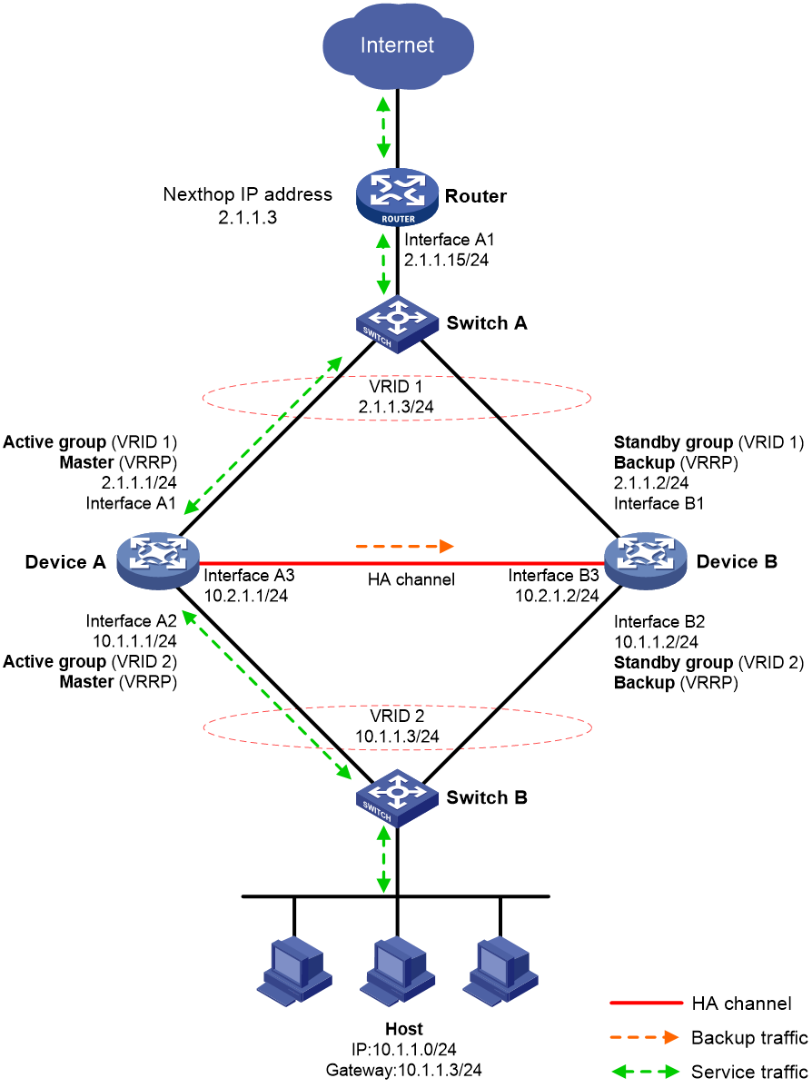
Figure 15 shows a typical model of routed in-path deployment in active/standby mode. The HA group is directly connected to the upstream and downstream Layer 2 switches by Layer 3 interfaces. To use this scheme in collaboration with VRRP, perform the following tasks:
· Establish HA channels between Device A and Device B.
· On Device A and Device B, create uplink VRRP group 1 and downlink VRRP group 2 and associate them with the HA group.
· On Device A, associate VRRP group 1 and VRRP group 2 with the VRRP active group. On Device B, associate VRRP group 1 and VRRP group 2 with the VRRP standby group.
· On Device A and Device B, specify the IP address of Interface A1 on the router (2.1.1.15) as the next hop of the route to the Internet.
· On the router, specify the virtual IP address of VRRP group 1 (2.1.1.3) as the next hop of the route to the host's subnet.
· On the host, specify the virtual IP address of VRRP group 2 (10.1.1.3) as the default gateway.
· On Switch A, assign the interfaces attached to the router, Device A, and Device B to the same VLAN.
· On Switch B, assign the interfaces attached to the host, Device A, and Device B to the same VLAN.
Figure 15 Routed in-path deployment in active/standby mode
The following shows how traffic is forwarded when the host accesses the Internet in Figure 15:
1. The host identifies that the destination IP address is on a different subnet and sends an ARP request to obtain the MAC address of the default gateway. In this example, the host does not have the ARP entry for the default gateway.
2. Switch B broadcasts the ARP request and learns the MAC address of the host.
3. Device A and Device B receives the ARP request, and Device A (master) replies with the virtual MAC address of VRRP group 2.
4. Switch B learns the MAC address entry for the virtual MAC address of VRRP group 2 and forwards the ARP reply to the host.
5. The host learns the virtual MAC address and sends the packets destined for the Internet to the default gateway.
6. Switch B forwards the packets to Device A (master). The traffic of the host will be processed and forwarded by Device A as long as it is the master.
7. Device A does not have the ARP entry for the next hop of the route to the Internet and sends an ARP request to obtain the MAC address of the next hop. In the ARP request, the source MAC address is the virtual MAC address of VRRP group 1.
8. Switch A and the router then perform typical forwarding and ARP and MAC address learning.
The forwarding process for the traffic sent from the Internet to the host is similar to the above process.
Routed in-path deployment in dual-active mode
Figure 16 shows a typical model of routed in-path deployment in dual-active mode. The HA group is directly connected to the upstream and downstream Layer 2 switches by Layer 3 interfaces. To use this scheme in collaboration with VRRP, perform the following tasks:
· Establish HA channels between Device A and Device B.
· On Device A and Device B, create two uplink VRRP groups and two downlink VRRP groups.
· Create VRRP group 3 and VRRP group 4 on the downlink interfaces of Device A and Device B.
· On Device A, associate VRRP group 1 and VRRP group 3 with the VRRP active group, and associate VRRP group 2 and VRRP group 4 with the VRRP standby group.
· On Device B, associate VRRP group 1 and VRRP group 3 with the VRRP standby group, and associate VRRP group 2 and VRRP group 4 with the VRRP active group.
· On Device A and Device B, specify the IP address of Interface A1 on the router (2.1.1.15) as the next hop of the route to the Internet.
· On the router, configure routes as follows:
¡ Specify the virtual IP address of VRRP group 1 (2.1.1.3) as the next hop of the route to Host A's subnet.
¡ Specify the virtual IP address of VRRP group 2 (2.1.1.4) as the next hop of the route to Host B's subnet.
· On Host A, specify the virtual IP address of VRRP group 3 (10.1.1.3) as the default gateway.
· On Host B, specify the virtual IP address of VRRP group 4 (10.1.1.4) as the default gateway.
· On Switch A, assign the interfaces attached to the router, Device A, and Device B to the same VLAN.
· On Switch B, assign the interfaces attached to the hosts, Device A, and Device B to the same VLAN.
Figure 16 Routed in-path deployment in dual-active mode
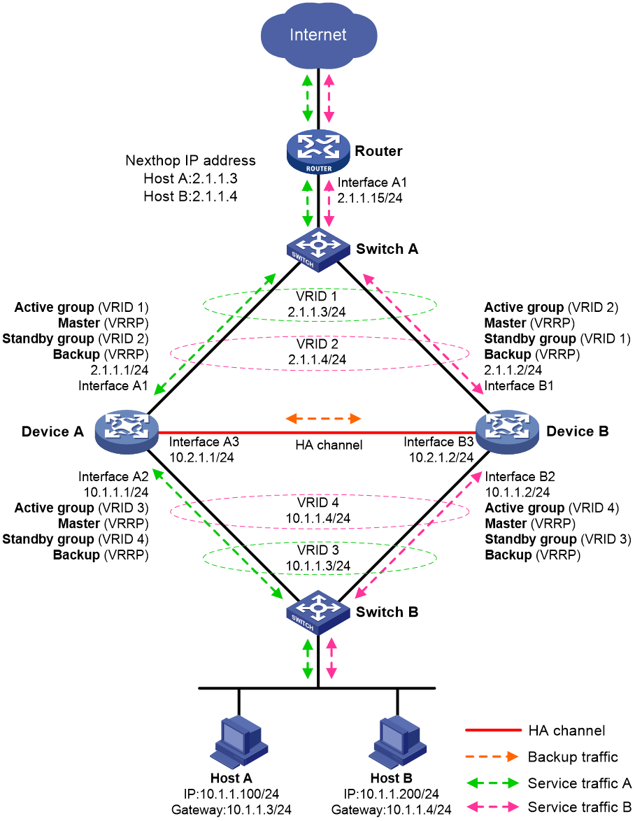
As shown in Figure 16, the traffic of Host A and Host B is distributed to Device A and Device B, respectively. The traffic forwarding process is similar to that in active/standby mode.
Transparent in-path deployment in active/standby mode
Figure 17 shows a typical model of transparent in-path deployment in active/standby mode. The Layer 2 HA group is directly connected to the upstream and downstream Layer 2 switches by Layer 2 interfaces. To use this scheme, perform the following tasks:
· Establish HA channels between Device A and Device B.
· On Device A and Device B, assign uplink and downlink interfaces to the same VLAN.
· Configure the HA group to monitor one of the following objects:
¡ The VLAN where Device A and Device B reside.
You do not need to enable spanning tree on the upstream and downstream switches.
¡ Uplink and downlink interfaces of Device A and Device B.
You must enable spanning tree on the upstream and downstream switches.
· On Switch A, assign the interfaces attached to the upstream router, Device A, and Device B to the same VLAN.
· On Switch B, assign the interfaces attached to the hosts, Device A, and Device B to the same VLAN.
Figure 17 Transparent in-path deployment in active/standby mode
Transparent in-path deployment in dual-active mode
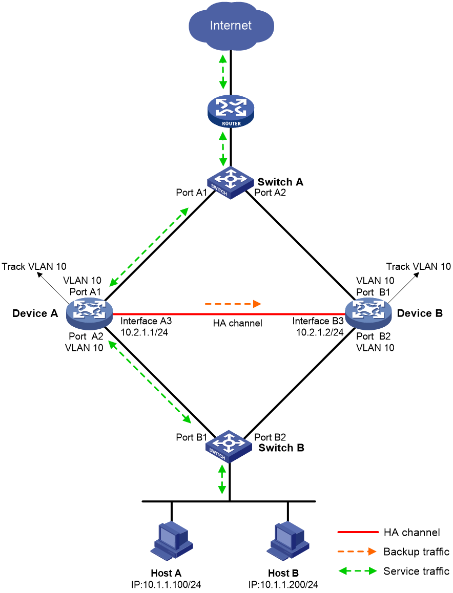
Figure 18 shows a typical model of transparent in-path deployment in dual-active mode. The Layer 2 HA group is directly connected to the upstream and downstream routers by Layer 2 interfaces. To use this scheme, perform the following tasks:
· Establish HA channels between Device A and Device B.
· On Device A and Device B, assign uplink and downlink interfaces to the same VLAN.
· On Device A and Device B, configure the HA group to monitor the status of the uplink and downlink interfaces.
· On Router A and Router B, configure the same cost for OSPF routes and enable per-flow load sharing among ECMP routes.
Figure 18 Transparent in-path deployment in dual-active mode
Display and maintenance commands for the HA group
Execute display commands in any view.
|
Task |
Command |
|
Display HA group status information. |
display remote-backup-group status |
|
Display the configuration consistency check result for the HA group. |
display remote-backup-group sync-check |
HA group configuration examples (IPv4)
Example: Configuring the HA group in active/standby mode in collaboration with VRRP
Network configuration
As shown in Figure 19, set up the HA group at the border between the Internet and the internal network of an enterprise to ensure service continuity.
· Configure the HA group to collaborate with VRRP.
· Configure the HA group to operate in active/standby mode.
· Configure Device A and Device B as the primary device and the secondary device, respectively.

Procedure
1. Verify that Device A and Device B have software and hardware environment consistency.
2. Configure Switch A:
|
|
NOTE: This step only provides the brief configuration procedure. |
# Create VLAN 10.
# Configure the interfaces attached to the HA group and the router to operate at Layer 2. Assign them to VLAN 10 as access interfaces.
3. Configure Switch B:
|
|
NOTE: This step only provides the brief configuration procedure. |
# Create VLAN 10.
# Configure the interfaces attached to the HA group and the host to operate at Layer 2. Assign them to VLAN 10 as access interfaces.
4. Configure the router:
|
|
NOTE: This step only provides the brief configuration procedure. |
# Assign 2.1.1.15/24 to GigabitEthernet 1/0/7.
# Configure routes as follows:
¡ Specify 2.1.1.3 (virtual IP address of VRRP group 1) as the next hop of the routes to the internal network.
¡ Specify the IP address of the peer interface attached to the traffic outgoing interface as the next hop of the route to the Internet.
5. Configure Device A:
a. Assign an IP address to GigabitEthernet 1/0/1.
<DeviceA> system-view
[DeviceA] interface gigabitethernet 1/0/1
[DeviceA-GigabitEthernet1/0/1] ip address 2.1.1.1 255.255.255.0
[DeviceA-GigabitEthernet1/0/1] quit
# Assign IP addresses to other interfaces in the same way. (Details not shown.)
b. Add interfaces to security zones.
[DeviceA] security-zone name untrust
[DeviceA-security-zone-Untrust] import interface gigabitethernet 1/0/1
[DeviceA-security-zone-Untrust] quit
[DeviceA] security-zone name trust
[DeviceA-security-zone-Trust] import interface gigabitethernet 1/0/2
[DeviceA-security-zone-Trust] quit
c. Configure settings for routing. This example configures a static route, and the next hop in the route is 2.1.1.15.
[DeviceA] ip route-static 0.0.0.0 0.0.0.0 2.1.1.15
d. Configure a security policy.
Perform this task only on the primary device. After the HA group is set up, the secondary device automatically synchronizes its security policy configuration with the primary device.
# Configure a rule named trust-untrust to permit the packets from 10.1.1.0/24 to the Internet.
[DeviceA] security-policy ip
[DeviceA-security-policy-ip] rule name trust-untrust
[DeviceA-security-policy-ip-3-trust-untrust] source-zone trust
[DeviceA-security-policy-ip-3-trust-untrust] destination-zone untrust
[DeviceA-security-policy-ip-3-trust-untrust] source-ip-subnet 10.1.1.0 24
[DeviceA-security-policy-ip-3-trust-untrust] action pass
[DeviceA-security-policy-ip-3-trust-untrust] quit
# Configure rules to permit VRRP protocol packets. When the HA channel is disconnected, Device A and Device B can exchange VRRP protocol packets to elect a VRRP master.
[DeviceA-security-policy-ip] rule name vrrp1
[DeviceA-security-policy-ip-4-vrrp1] source-zone trust
[DeviceA-security-policy-ip-4-vrrp1] destination-zone local
[DeviceA-security-policy-ip-4-vrrp1] service vrrp
[DeviceA-security-policy-ip-4-vrrp1] action pass
[DeviceA-security-policy-ip-4-vrrp1] quit
[DeviceA-security-policy-ip] rule name vrrp2
[DeviceA-security-policy-ip-5-vrrp2] source-zone local
[DeviceA-security-policy-ip-5-vrrp2] destination-zone trust
[DeviceA-security-policy-ip-5-vrrp2] service vrrp
[DeviceA-security-policy-ip-5-vrrp2] action pass
[DeviceA-security-policy-ip-5-vrrp2] quit
[DeviceA-security-policy-ip] rule name vrrp3
[DeviceA-security-policy-ip-6-vrrp3] source-zone untrust
[DeviceA-security-policy-ip-6-vrrp3] destination-zone local
[DeviceA-security-policy-ip-6-vrrp3] service vrrp
[DeviceA-security-policy-ip-6-vrrp3] action pass
[DeviceA-security-policy-ip-6-vrrp3] quit
[DeviceA-security-policy-ip] rule name vrrp4
[DeviceA-security-policy-ip-7-vrrp4] source-zone local
[DeviceA-security-policy-ip-7-vrrp4] destination-zone untrust
[DeviceA-security-policy-ip-7-vrrp4] service vrrp
[DeviceA-security-policy-ip-7-vrrp4] action pass
[DeviceA-security-policy-ip-7-vrrp4] quit
[DeviceA-security-policy-ip] quit
e. Configure HA group settings.
# Set up an HA group.
[DeviceA] remote-backup group
[DeviceA-remote-backup-group] remote-ip 10.2.1.2
[DeviceA-remote-backup-group] local-ip 10.2.1.1
[DeviceA-remote-backup-group] data-channel interface gigabitethernet 1/0/3
[DeviceA-remote-backup-group] device-role primary
RBM_P[DeviceA-remote-backup-group] undo backup-mode
RBM_P[DeviceA-remote-backup-group] hot-backup enable
RBM_P[DeviceA-remote-backup-group] configuration auto-sync enable
RBM_P[DeviceA-remote-backup-group] configuration sync-check interval 12
RBM_P[DeviceA-remote-backup-group] quit
# Create VRRP groups and associate them with the HA group.
RBM_P[DeviceA] interface gigabitethernet 1/0/1
RBM_P[DeviceA-GigabitEthernet1/0/1] vrrp vrid 1 virtual-ip 2.1.1.3 active
RBM_P[DeviceA-GigabitEthernet1/0/1] quit
RBM_P[DeviceA] interface gigabitethernet 1/0/2
RBM_P[DeviceA-GigabitEthernet1/0/2] vrrp vrid 2 virtual-ip 10.1.1.3 active
RBM_P[DeviceA-GigabitEthernet1/0/2] quit
f. Configure security services on Device A. (Details not shown.)
6. Configure Device B:
a. Assign an IP address to GigabitEthernet 1/0/1.
<DeviceB> system-view
[DeviceB] interface gigabitethernet 1/0/1
[DeviceB-GigabitEthernet1/0/1] ip address 2.1.1.2 255.255.255.0
[DeviceB-GigabitEthernet1/0/1] quit
# Assign IP addresses to other interfaces in the same way. (Details not shown.)
b. Add interfaces to security zones.
[DeviceB] security-zone name untrust
[DeviceB-security-zone-Untrust] import interface gigabitethernet 1/0/1
[DeviceB-security-zone-Untrust] quit
[DeviceB] security-zone name trust
[DeviceB-security-zone-Trust] import interface gigabitethernet 1/0/2
[DeviceB-security-zone-Trust] quit
c. Configure settings for routing. This example configures a static route, and the next hop in the route is 2.1.1.15.
[DeviceB] ip route-static 0.0.0.0 0.0.0.0 2.1.1.15
d. Configure HA group settings.
# Set up an HA group.
[DeviceB] remote-backup group
[DeviceB-remote-backup-group] remote-ip 10.2.1.1
[DeviceB-remote-backup-group] local-ip 10.2.1.2
[DeviceB-remote-backup-group] data-channel interface gigabitethernet 1/0/3
[DeviceB-remote-backup-group] device-role secondary
RBM_S[DeviceB-remote-backup-group] undo backup-mode
RBM_S[DeviceB-remote-backup-group] hot-backup enable
RBM_S[DeviceB-remote-backup-group] configuration auto-sync enable
RBM_S[DeviceB-remote-backup-group] configuration sync-check interval 12
RBM_S[DeviceB-remote-backup-group] quit
# Create VRRP groups and associate them with the HA group.
RBM_S[DeviceB] interface gigabitethernet 1/0/1
RBM_S[DeviceB-GigabitEthernet1/0/1] vrrp vrid 1 virtual-ip 2.1.1.3 standby
RBM_S[DeviceB-GigabitEthernet1/0/1] quit
RBM_S[DeviceB] interface gigabitethernet 1/0/2
RBM_S[DeviceB-GigabitEthernet1/0/2] vrrp vrid 2 virtual-ip 10.1.1.3 standby
RBM_S[DeviceB-GigabitEthernet1/0/2] quit
7. On the host, specify 10.1.1.3 (virtual IP address of VRRP group 2) as the default gateway. (Details not shown.)
Verifying the configuration
1. Verify the configuration on Device A:
# Verify that the HA channels have been set up.
RBM_P[DeviceA] display remote-backup-group status
Remote backup group information:
Backup mode: Active/standby
Device management role: Primary
Device running status: Active
Data channel interface: GigabitEthernet1/0/3
Local IP: 10.2.1.1
Remote IP: 10.2.1.2 Destination port: 60064
Control channel status: Connected
Keepalive interval: 1s
Keepalive count: 10
Configuration consistency check interval: 12 hour
Configuration consistency check result: Not Performed
Configuration backup status: Auto sync enabled
Session backup status: Hot backup enabled
Delay-time: 0 min
Uptime since last switchover: 0 days, 3 hours, 11 minutes
Switchover records:
Time Status change Cause
2021-06-22 13:33:33 Initial to Active Interface status changed
# Verify that Device A is the master in all VRRP groups.
RBM_P[DeviceA] display vrrp
IPv4 Virtual Router Information:
Running mode : Standard
RBM control channel is established
VRRP active group status : Master
VRRP standby group status: Master
Total number of virtual routers : 2
Interface VRID State Running Adver Auth Virtual
Pri Timer Type IP
---------------------------------------------------------------------
GE1/0/1 1 Master 100 100 None 2.1.1.3
GE1/0/2 2 Master 100 100 None 10.1.1.3
# Enable logging for the security policy that permits communication between security zones Trust and Untrust. Verity that Device A generates log messages when the host communicates with the Internet. (Details not shown.)
2. Verify the configuration on Device B:
# Verify that the HA channels have been set up.
RBM_S[DeviceB] display remote-backup-group status
Remote backup group information:
Backup mode: Active/standby
Device management role: Secondary
Device running status: Standby
Data channel interface: GigabitEthernet1/0/3
Local IP: 10.2.1.2
Remote IP: 10.2.1.1 Destination port: 60064
Control channel status: Connected
Keepalive interval: 1s
Keepalive count: 10
Configuration consistency check interval: 12 hour
Configuration consistency check result: Not Performed
Configuration backup status: Auto sync enabled
Session backup status: Hot backup enabled
Delay-time: 0 min
Uptime since last switchover: 0 days, 3 hours, 11 minutes
Switchover records:
Time Status change Cause
2021-06-22 13:33:33 Initial to Active Interface status changed
# Verify that Device A is the backup in all VRRP groups.
RBM_S[DeviceB] display vrrp
IPv4 Virtual Router Information:
Running mode : Standard
RBM control channel is established
VRRP active group status : Backup
VRRP standby group status: Backup
Total number of virtual routers : 2
Interface VRID State Running Adver Auth Virtual
Pri Timer Type IP
---------------------------------------------------------------------
GE1/0/1 1 Backup 100 100 None 2.1.1.3
GE1/0/2 2 Backup 100 100 None 10.1.1.3
# Enable logging for the security policy that permits communication between security zones Trust and Untrust. Verity that Device B does not generate log messages when the host communicates with the Internet. (Details not shown.)
Example: Configuring the HA group in dual-active mode in collaboration with VRRP
Network configuration
As shown in Figure 20, set up the HA group at the border between the Internet and the internal network of an enterprise to ensure service continuity.
· Configure the HA group to collaborate with VRRP.
· Configure the HA group to operate in dual-active mode.
· Configure Device A and Device B to load share traffic.

Procedure
1. Verify that Device A and Device B have software and hardware environment consistency.
2. Configure Switch A:
|
|
NOTE: This step only provides the brief configuration procedure. |
# Create VLAN 10.
# Configure the interfaces attached to the HA group and the router to operate at Layer 2. Assign them to VLAN 10 as access interfaces.
3. Configure Switch B:
|
|
NOTE: This step only provides the brief configuration procedure. |
# Create VLAN 10.
# Configure the interfaces attached to the HA group and the host to operate at Layer 2. Assign them to VLAN 10 as access interfaces.
4. Configure the router:
|
|
NOTE: This step only provides the brief configuration procedure. |
# Assign 2.1.1.15/24 to GigabitEthernet 1/0/7.
# Configure routes as follows:
¡ Specify 2.1.1.3 (virtual IP address of VRRP group 1) as the next hop of the routes to some subnets of the internal network. Specify 2.1.1.4 (virtual IP address of VRRP group 2) as the next hop of the routes to the other subnets of the internal network.
¡ Specify the IP address of the peer interface attached to the traffic outgoing interface as the next hop of the route to the Internet.
5. Configure Device A:
a. Assign an IP address to GigabitEthernet 1/0/1.
<DeviceA> system-view
[DeviceA] interface gigabitethernet 1/0/1
[DeviceA-GigabitEthernet1/0/1] ip address 2.1.1.1 255.255.255.0
[DeviceA-GigabitEthernet1/0/1] quit
# Assign IP addresses to other interfaces in the same way. (Details not shown.)
b. Add interfaces to security zones.
[DeviceA] security-zone name untrust
[DeviceA-security-zone-Untrust] import interface gigabitethernet 1/0/1
[DeviceA-security-zone-Untrust] quit
[DeviceA] security-zone name trust
[DeviceA-security-zone-Trust] import interface gigabitethernet 1/0/2
[DeviceA-security-zone-Trust] quit
c. Configure settings for routing. This example configures a static route, and the next hop in the route is 2.1.1.15.
[DeviceA] ip route-static 0.0.0.0 0.0.0.0 2.1.1.15
d. Configure a security policy.
Perform this task only on the primary device. After the HA group is set up, the secondary device automatically synchronizes its security policy configuration with the primary device.
# Configure a rule named trust-untrust to permit the packets from 10.1.1.0/24 to the Internet.
[DeviceA] security-policy ip
[DeviceA-security-policy-ip] rule name trust-untrust
[DeviceA-security-policy-ip-3-trust-untrust] source-zone trust
[DeviceA-security-policy-ip-3-trust-untrust] destination-zone untrust
[DeviceA-security-policy-ip-3-trust-untrust] source-ip-subnet 10.1.1.0 24
[DeviceA-security-policy-ip-3-trust-untrust] action pass
[DeviceA-security-policy-ip-3-trust-untrust] quit
# Configure rules to permit VRRP protocol packets. When the HA channel is disconnected, Device A and Device B can exchange VRRP protocol packets to elect a VRRP master.
[DeviceA-security-policy-ip] rule name vrrp1
[DeviceA-security-policy-ip-4-vrrp1] source-zone trust
[DeviceA-security-policy-ip-4-vrrp1] destination-zone local
[DeviceA-security-policy-ip-4-vrrp1] service vrrp
[DeviceA-security-policy-ip-4-vrrp1] action pass
[DeviceA-security-policy-ip-4-vrrp1] quit
[DeviceA-security-policy-ip] rule name vrrp2
[DeviceA-security-policy-ip-5-vrrp2] source-zone local
[DeviceA-security-policy-ip-5-vrrp2] destination-zone trust
[DeviceA-security-policy-ip-5-vrrp2] service vrrp
[DeviceA-security-policy-ip-5-vrrp2] action pass
[DeviceA-security-policy-ip-5-vrrp2] quit
[DeviceA-security-policy-ip] rule name vrrp3
[DeviceA-security-policy-ip-6-vrrp3] source-zone untrust
[DeviceA-security-policy-ip-6-vrrp3] destination-zone local
[DeviceA-security-policy-ip-6-vrrp3] service vrrp
[DeviceA-security-policy-ip-6-vrrp3] action pass
[DeviceA-security-policy-ip-6-vrrp3] quit
[DeviceA-security-policy-ip] rule name vrrp4
[DeviceA-security-policy-ip-7-vrrp4] source-zone local
[DeviceA-security-policy-ip-7-vrrp4] destination-zone untrust
[DeviceA-security-policy-ip-7-vrrp4] service vrrp
[DeviceA-security-policy-ip-7-vrrp4] action pass
[DeviceA-security-policy-ip-7-vrrp4] quit
[DeviceA-security-policy-ip] quit
e. Configure HA group settings.
# Set up an HA group.
[DeviceA] remote-backup group
[DeviceA-remote-backup-group] remote-ip 10.2.1.2
[DeviceA-remote-backup-group] local-ip 10.2.1.1
[DeviceA-remote-backup-group] data-channel interface gigabitethernet 1/0/3
[DeviceA-remote-backup-group] device-role primary
RBM_P[DeviceA-remote-backup-group] backup-mode dual-active
RBM_P[DeviceA-remote-backup-group] hot-backup enable
RBM_P[DeviceA-remote-backup-group] configuration auto-sync enable
RBM_P[DeviceA-remote-backup-group] configuration sync-check interval 12
RBM_P[DeviceA-remote-backup-group] delay-time 1
RBM_P[DeviceA-remote-backup-group] quit
# Create VRRP groups and associate them with the HA group.
RBM_P[DeviceA] interface gigabitethernet 1/0/1
RBM_P[DeviceA-GigabitEthernet1/0/1] vrrp vrid 1 virtual-ip 2.1.1.3 active
RBM_P[DeviceA-GigabitEthernet1/0/1] vrrp vrid 2 virtual-ip 2.1.1.4 standby
RBM_P[DeviceA-GigabitEthernet1/0/1] quit
RBM_P[DeviceA] interface gigabitethernet 1/0/2
RBM_P[DeviceA-GigabitEthernet1/0/2] vrrp vrid 3 virtual-ip 10.1.1.3 active
RBM_P[DeviceA-GigabitEthernet1/0/2] vrrp vrid 4 virtual-ip 10.1.1.4 standby
RBM_P[DeviceA-GigabitEthernet1/0/2] quit
f. Configure security services on Device A. (Details not shown.)
6. Configure Device B:
a. Assign an IP address to GigabitEthernet 1/0/1.
<DeviceB> system-view
[DeviceB] interface gigabitethernet 1/0/1
[DeviceB-GigabitEthernet1/0/1] ip address 2.1.1.2 255.255.255.0
[DeviceB-GigabitEthernet1/0/1] quit
# Assign IP addresses to other interfaces in the same way. (Details not shown.)
b. Add interfaces to security zones.
[DeviceB] security-zone name untrust
[DeviceB-security-zone-Untrust] import interface gigabitethernet 1/0/1
[DeviceB-security-zone-Untrust] quit
[DeviceB] security-zone name trust
[DeviceB-security-zone-Trust] import interface gigabitethernet 1/0/2
[DeviceB-security-zone-Trust] quit
c. Configure settings for routing. This example configures a static route, and the next hop in the route is 2.1.1.15.
[DeviceB] ip route-static 0.0.0.0 0.0.0.0 2.1.1.15
d. Configure HA group settings.
# Set up an HA group.
[DeviceB] remote-backup group
[DeviceB-remote-backup-group] remote-ip 10.2.1.1
[DeviceB-remote-backup-group] local-ip 10.2.1.2
[DeviceB-remote-backup-group] data-channel interface gigabitethernet 1/0/3
[DeviceB-remote-backup-group] device-role secondary
RBM_S[DeviceB-remote-backup-group] backup-mode dual-active
RBM_S[DeviceB-remote-backup-group] hot-backup enable
RBM_S[DeviceB-remote-backup-group] configuration auto-sync enable
RBM_S[DeviceB-remote-backup-group] configuration sync-check interval 12
RBM_S[DeviceB-remote-backup-group] delay-time 1
RBM_S[DeviceB-remote-backup-group] quit
# Create VRRP groups and associate them with the HA group.
RBM_S[DeviceB] interface gigabitethernet 1/0/1
RBM_S[DeviceB-GigabitEthernet1/0/1] vrrp vrid 1 virtual-ip 2.1.1.3 standby
RBM_S[DeviceB-GigabitEthernet1/0/1] vrrp vrid 2 virtual-ip 2.1.1.4 active
RBM_S[DeviceB-GigabitEthernet1/0/1] quit
RBM_S[DeviceB] interface gigabitethernet 1/0/2
RBM_S[DeviceB-GigabitEthernet1/0/2] vrrp vrid 3 virtual-ip 10.1.1.3 standby
RBM_S[DeviceB-GigabitEthernet1/0/2] vrrp vrid 4 virtual-ip 10.1.1.4 active
RBM_S[DeviceB-GigabitEthernet1/0/2] quit
7. On some hosts, specify 10.1.1.3 (virtual IP address of VRRP group 3) as the default gateway. On the other hosts, specify 10.1.1.4 (virtual IP address of VRRP group 4) as the default gateway. (Details not shown.)
Verifying the configuration
1. Verify the configuration on Device A:
# Verify that the HA channels have been set up.
RBM_P[DeviceA] display remote-backup-group status
Remote backup group information:
Backup mode: Dual-active
Device management role: Primary
Device running status: Active
Data channel interface: GigabitEthernet1/0/3
Local IP: 10.2.1.1
Remote IP: 10.2.1.2 Destination port: 60064
Control channel status: Connected
Keepalive interval: 1s
Keepalive count: 10
Configuration consistency check interval: 12 hour
Configuration consistency check result: Not Performed
Configuration backup status: Auto sync enabled
Session backup status: Hot backup enabled
Delay-time: 1 min
Uptime since last switchover: 0 days, 3 hours, 11 minutes
Switchover records:
Time Status change Cause
2021-06-22 13:33:33 Initial to Active Interface status changed
# Verify that Device A is the master in VRRP groups 1 and 3 and the backup in VRRP groups 2 and 4.
RBM_P[DeviceA] display vrrp
IPv4 Virtual Router Information:
Running mode : Standard
RBM control channel is established
VRRP active group status : Master
VRRP standby group status: Backup
Total number of virtual routers : 4
Interface VRID State Running Adver Auth Virtual
Pri Timer Type IP
---------------------------------------------------------------------
GE1/0/1 1 Master 100 100 None 2.1.1.3
GE1/0/1 2 Backup 100 100 None 2.1.1.4
GE1/0/2 3 Master 100 100 None 10.1.1.3
GE1/0/2 4 Backup 100 100 None 10.1.1.4
# Enable logging for the security policy that permits communication between security zones Trust and Untrust. Verity that Device A generates log messages when a host for which Device A forwards traffic communicates with the Internet. Verity that Device A does not generate log messages when a host for which Device B forwards traffic communicates with the Internet. (Details not shown.)
2. Verify the configuration on Device B:
# Verify that the HA channels have been set up.
RBM_S[DeviceB] display remote-backup-group status
Remote backup group information:
Backup mode: Dual-active
Device management role: Secondary
Device running status: Active
Data channel interface: GigabitEthernet1/0/3
Local IP: 10.2.1.2
Remote IP: 10.2.1.1 Destination port: 60064
Control channel status: Connected
Keepalive interval: 1s
Keepalive count: 10
Configuration consistency check interval: 12 hour
Configuration consistency check result: Not Performed
Configuration backup status: Auto sync enabled
Session backup status: Hot backup enabled
Delay-time: 1 min
Uptime since last switchover: 0 days, 3 hours, 11 minutes
Switchover records:
Time Status change Cause
2021-06-22 13:33:33 Initial to Active Interface status changed
# Verify that Device B is the master in VRRP groups 2 and 4 and the backup in VRRP groups 1 and 3.
RBM_S[DeviceB] display vrrp
IPv4 Virtual Router Information:
Running mode : Standard
RBM control channel is established
VRRP active group status : Master
VRRP standby group status: Backup
Total number of virtual routers : 4
Interface VRID State Running Adver Auth Virtual
Pri Timer Type IP
---------------------------------------------------------------------
GE1/0/1 1 Backup 100 100 None 2.1.1.3
GE1/0/1 2 Master 100 100 None 2.1.1.4
GE1/0/2 3 Backup 100 100 None 10.1.1.3
GE1/0/2 4 Master 100 100 None 10.1.1.4
# Enable logging for the security policy that permits communication between security zones Trust and Untrust. Verity that Device B generates log messages when a host for which Device B forwards traffic communicates with the Internet. Verity that Device B does not generate log messages when a host for which Device A forwards traffic communicates with the Internet. (Details not shown.)
Example: Configuring the HA group in active/standby mode in collaboration with a routing protocol
Network configuration
As shown in Figure 21, set up the HA group at the border between the Internet and the internal network of an enterprise to ensure service continuity.
· Configure the HA group to collaborate with OSPF.
· Configure the HA group to operate in active/standby mode.
· Configure Device A and Device B as the primary device and the secondary device, respectively.
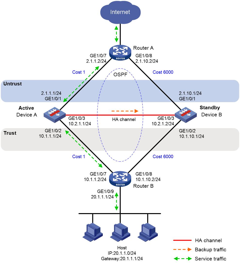
Procedure
1. Verify that Device A and Device B have software and hardware environment consistency.
2. Configure Router A:
|
|
NOTE: This step only provides the brief configuration procedure. |
# Assign 2.1.1.2/24 to GigabitEthernet 1/0/7.
# Assign 2.1.10.2/24 to GigabitEthernet 1/0/8.
# Configure OSPF for Device A, Device B, and the routers to have Layer 3 reachability.
3. Configure Router B:
|
|
NOTE: This step only provides the brief configuration procedure. |
# Assign 10.1.1.2/24 to GigabitEthernet 1/0/7.
# Assign 10.1.10.2/24 to GigabitEthernet 1/0/8.
# Configure OSPF for Device A, Device B, and the routers to have Layer 3 reachability.
4. Configure Device A:
a. Assign an IP address to GigabitEthernet 1/0/1.
<DeviceA> system-view
[DeviceA] interface gigabitethernet 1/0/1
[DeviceA-GigabitEthernet1/0/1] ip address 2.1.1.1 255.255.255.0
[DeviceA-GigabitEthernet1/0/1] quit
# Assign IP addresses to other interfaces in the same way. (Details not shown.)
b. Add interfaces to security zones.
[DeviceA] security-zone name untrust
[DeviceA-security-zone-Untrust] import interface gigabitethernet 1/0/1
[DeviceA-security-zone-Untrust] quit
[DeviceA] security-zone name trust
[DeviceA-security-zone-Trust] import interface gigabitethernet 1/0/2
[DeviceA-security-zone-Trust] quit
c. Configure OSPF. Use the default OSPF link cost configuration.
[DeviceA] router id 2.1.1.1
[DeviceA] ospf
[DeviceA-ospf-1] area 0
[DeviceA-ospf-1-area-0.0.0.0] network 2.1.1.0 0.0.0.255
[DeviceA-ospf-1-area-0.0.0.0] network 10.1.1.0 0.0.0.255
[DeviceA-ospf-1-area-0.0.0.0] quit
[DeviceA-ospf-1] quit
d. Configure a security policy.
Perform this task only on the primary device. After the HA group is set up, the secondary device automatically synchronizes its security policy configuration with the primary device.
# Configure a rule named trust-untrust to permit the packets from 20.1.1.0/24 to the Internet.
[DeviceA] security-policy ip
[DeviceA-security-policy-ip] rule name trust-untrust
[DeviceA-security-policy-ip-3-trust-untrust] source-zone trust
[DeviceA-security-policy-ip-3-trust-untrust] destination-zone untrust
[DeviceA-security-policy-ip-3-trust-untrust] source-ip-subnet 20.1.1.0 24
[DeviceA-security-policy-ip-3-trust-untrust] action pass
[DeviceA-security-policy-ip-3-trust-untrust] quit
# Configure rules to permit OSPF protocol packets.
[DeviceA-security-policy-ip] rule name ospf1
[DeviceA-security-policy-ip-4-ospf1] source-zone trust
[DeviceA-security-policy-ip-4-ospf1] destination-zone local
[DeviceA-security-policy-ip-4-ospf1] service ospf
[DeviceA-security-policy-ip-4-ospf1] action pass
[DeviceA-security-policy-ip-4-ospf1] quit
[DeviceA-security-policy-ip] rule name ospf2
[DeviceA-security-policy-ip-5-ospf2] source-zone local
[DeviceA-security-policy-ip-5-ospf2] destination-zone trust
[DeviceA-security-policy-ip-5-ospf2] service ospf
[DeviceA-security-policy-ip-5-ospf2] action pass
[DeviceA-security-policy-ip-5-ospf2] quit
[DeviceA-security-policy-ip] rule name ospf3
[DeviceA-security-policy-ip-6-ospf3] source-zone untrust
[DeviceA-security-policy-ip-6-ospf3] destination-zone local
[DeviceA-security-policy-ip-6-ospf3] service ospf
[DeviceA-security-policy-ip-6-ospf3] action pass
[DeviceA-security-policy-ip-6-ospf3] quit
[DeviceA-security-policy-ip] rule name ospf4
[DeviceA-security-policy-ip-7-ospf4] source-zone local
[DeviceA-security-policy-ip-7-ospf4] destination-zone untrust
[DeviceA-security-policy-ip-7-ospf4] service ospf
[DeviceA-security-policy-ip-7-ospf4] action pass
[DeviceA-security-policy-ip-7-ospf4] quit
[DeviceA-security-policy-ip] quit
e. Configure HA group settings.
# Associate track entries with interfaces.
[DeviceA] track 1 interface gigabitethernet 1/0/1
[DeviceA-track-1] quit
[DeviceA] track 2 interface gigabitethernet 1/0/2
[DeviceA-track-2] quit
# Set up an HA group.
[DeviceA] remote-backup group
[DeviceA-remote-backup-group] remote-ip 10.2.1.2
[DeviceA-remote-backup-group] local-ip 10.2.1.1
[DeviceA-remote-backup-group] data-channel interface gigabitethernet 1/0/3
[DeviceA-remote-backup-group] device-role primary
RBM_P[DeviceA-remote-backup-group] undo backup-mode
RBM_P[DeviceA-remote-backup-group] hot-backup enable
RBM_P[DeviceA-remote-backup-group] configuration auto-sync enable
RBM_P[DeviceA-remote-backup-group] configuration sync-check interval 12
# Configure the HA group to change the link costs advertised in OSPF routes to 6000.
RBM_P[DeviceA-remote-backup-group] adjust-cost ospf enable absolute 6000
# Configure the HA group to monitor the status of track entry 1 and track entry 2.
RBM_P[DeviceA-remote-backup-group] track 1
RBM_P[DeviceA-remote-backup-group] track 2
RBM_P[DeviceA-remote-backup-group] quit
f. Configure security services on Device A. (Details not shown.)
5. Configure Device B:
a. Assign an IP address to GigabitEthernet 1/0/1.
<DeviceB> system-view
[DeviceB] interface gigabitethernet 1/0/1
[DeviceB-GigabitEthernet1/0/1] ip address 2.1.10.1 255.255.255.0
[DeviceB-GigabitEthernet1/0/1] quit
# Assign IP addresses to other interfaces in the same way. (Details not shown.)
b. Add interfaces to security zones.
[DeviceB] security-zone name untrust
[DeviceB-security-zone-Untrust] import interface gigabitethernet 1/0/1
[DeviceB-security-zone-Untrust] quit
[DeviceB] security-zone name trust
[DeviceB-security-zone-Trust] import interface gigabitethernet 1/0/2
[DeviceB-security-zone-Trust] quit
c. Configure OSPF. Use the default OSPF link cost configuration.
[DeviceB] router id 2.1.10.1
[DeviceB] ospf
[DeviceB-ospf-1] area 0
[DeviceB-ospf-1-area-0.0.0.0] network 2.1.10.0 0.0.0.255
[DeviceB-ospf-1-area-0.0.0.0] network 10.1.10.0 0.0.0.255
[DeviceB-ospf-1-area-0.0.0.0] quit
[DeviceB-ospf-1] quit
# Associate track entries with interfaces.
[DeviceB] track 1 interface gigabitethernet 1/0/1
[DeviceB-track-1] quit
[DeviceB] track 2 interface gigabitethernet 1/0/2
[DeviceB-track-2] quit
# Set up an HA group.
[DeviceB] remote-backup group
[DeviceB-remote-backup-group] remote-ip 10.2.1.1
[DeviceB-remote-backup-group] local-ip 10.2.1.2
[DeviceB-remote-backup-group] data-channel interface gigabitethernet 1/0/3
[DeviceB-remote-backup-group] device-role secondary
RBM_S[DeviceB-remote-backup-group] undo backup-mode
RBM_S[DeviceB-remote-backup-group] hot-backup enable
RBM_S[DeviceB-remote-backup-group] configuration auto-sync enable
RBM_S[DeviceB-remote-backup-group] configuration sync-check interval 12
# Configure the HA group to change the link costs advertised in OSPF routes to 6000.
RBM_S[DeviceB-remote-backup-group] adjust-cost ospf enable absolute 6000
# Configure the HA group to monitor the status of track entry 1 and track entry 2.
RBM_S[DeviceB-remote-backup-group] track 1
RBM_S[DeviceB-remote-backup-group] track 2
RBM_S[DeviceB-remote-backup-group] quit
6. On the host, specify 20.1.1.1 as the default gateway. (Details not shown.)
Verifying the configuration
1. Verify the configuration on Device A:
# Verify that the HA channels have been set up.
RBM_P[DeviceA] display remote-backup-group status
Remote backup group information:
Backup mode: Active/standby
Device management role: Primary
Device running status: Active
Data channel interface: GigabitEthernet1/0/3
Local IP: 10.2.1.1
Remote IP: 10.2.1.2 Destination port: 60064
Control channel status: Connected
Keepalive interval: 1s
Keepalive count: 10
Configuration consistency check interval: 12 hour
Configuration consistency check result: Not Performed
Configuration backup status: Auto sync enabled
Session backup status: Hot backup enabled
Delay-time: 0 min
Uptime since last switchover: 0 days, 3 hours, 11 minutes
Switchover records:
Time Status change Cause
2021-06-22 13:33:33 Initial to Active Interface status changed
# Verify that the OSPF routes advertised by Device A include a smaller link cost than that advertised by Device B.
RBM_P[DeviceA] display ospf interface
OSPF Process 1 with Router ID 2.1.1.1
Interfaces
Area: 0.0.0.0
IP Address Type State Cost Pri DR BDR
2.1.1.1 Broadcast BDR 1 1 2.1.1.2 2.1.1.1
10.1.1.1 Broadcast DR 1 1 10.1.1.1 10.1.1.2
2. Verify the configuration on Device B:
# Verify that the HA channels have been set up.
RBM_S[DeviceB] display remote-backup-group status
Remote backup group information:
Backup mode: Active/standby
Device management role: Secondary
Device running status: Standby
Data channel interface: GigabitEthernet1/0/3
Local IP: 10.2.1.2
Remote IP: 10.2.1.1 Destination port: 60064
Control channel status: Connected
Keepalive interval: 1s
Keepalive count: 10
Configuration consistency check interval: 12 hour
Configuration consistency check result: Not Performed
Configuration backup status: Auto sync enabled
Session backup status: Hot backup enabled
Delay-time: 0 min
Uptime since last switchover: 0 days, 3 hours, 11 minutes
Switchover records:
Time Status change Cause
2021-06-22 13:33:33 Initial to Active Interface status changed
# Verify that the OSPF routes advertised by Device B include a larger link cost than that advertised by Device A.
RBM_S[DeviceB] display ospf interface
OSPF Process 1 with Router ID 2.1.10.1
Interfaces
Area: 0.0.0.0
IP Address Type State Cost Pri DR BDR
2.1.10.1 Broadcast BDR 6000 1 2.1.10.2 2.1.10.1
10.1.10.1 Broadcast BDR 6000 1 10.1.10.2 10.1.10.1
Example: Configuring the HA group in dual-active mode in collaboration with a routing protocol
Network configuration
As shown in Figure 22, set up the HA group at the border between the Internet and the internal network of an enterprise to ensure service continuity.
· Configure the HA group to collaborate with OSPF.
· Configure the HA group to operate in dual-active mode.
· Configure Device A and Device B to load share traffic.
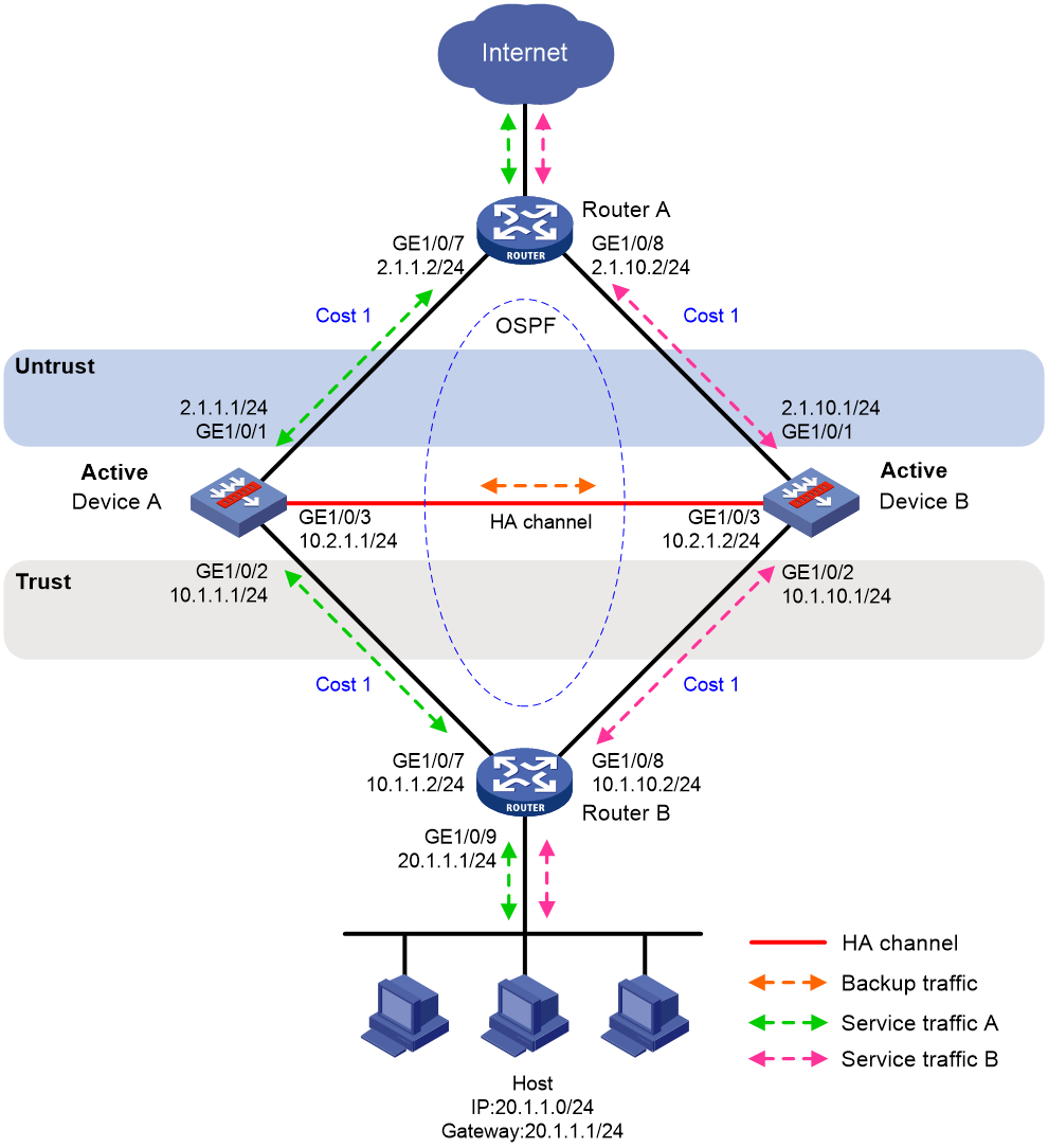
Procedure
1. Verify that Device A and Device B have software and hardware environment consistency.
2. Configure Router A:
|
|
NOTE: This step only provides the brief configuration procedure. |
# Assign 2.1.1.2/24 to GigabitEthernet 1/0/7.
# Assign 2.1.10.2/24 to GigabitEthernet 1/0/8.
# Configure OSPF for Device A, Device B, and the routers to have Layer 3 reachability.
# Configure per-flow load sharing for IP forwarding.
3. Configure Router B:
|
|
NOTE: This step only provides the brief configuration procedure. |
# Assign 10.1.1.2/24 to GigabitEthernet 1/0/7.
# Assign 10.1.10.2/24 to GigabitEthernet 1/0/8.
# Configure OSPF for Device A, Device B, and the routers to have Layer 3 reachability.
# Configure per-flow load sharing for IP forwarding.
4. Configure Device A:
a. Assign an IP address to GigabitEthernet 1/0/1.
<DeviceA> system-view
[DeviceA] interface gigabitethernet 1/0/1
[DeviceA-GigabitEthernet1/0/1] ip address 2.1.1.1 255.255.255.0
[DeviceA-GigabitEthernet1/0/1] quit
# Assign IP addresses to other interfaces in the same way. (Details not shown.)
b. Add interfaces to security zones.
[DeviceA] security-zone name untrust
[DeviceA-security-zone-Untrust] import interface gigabitethernet 1/0/1
[DeviceA-security-zone-Untrust] quit
[DeviceA] security-zone name trust
[DeviceA-security-zone-Trust] import interface gigabitethernet 1/0/2
[DeviceA-security-zone-Trust] quit
c. Configure OSPF. Use the default OSPF link cost configuration.
[DeviceA] router id 2.1.1.1
[DeviceA] ospf
[DeviceA-ospf-1] area 0
[DeviceA-ospf-1-area-0.0.0.0] network 2.1.1.0 0.0.0.255
[DeviceA-ospf-1-area-0.0.0.0] network 10.1.1.0 0.0.0.255
[DeviceA-ospf-1-area-0.0.0.0] quit
[DeviceA-ospf-1] quit
d. Configure a security policy.
Perform this task only on the primary device. After the HA group is set up, the secondary device automatically synchronizes its security policy configuration with the primary device.
# Configure a rule named trust-untrust to permit the packets from 20.1.1.0/24 to the Internet.
[DeviceA] security-policy ip
[DeviceA-security-policy-ip] rule name trust-untrust
[DeviceA-security-policy-ip-3-trust-untrust] source-zone trust
[DeviceA-security-policy-ip-3-trust-untrust] destination-zone untrust
[DeviceA-security-policy-ip-3-trust-untrust] source-ip-subnet 20.1.1.0 24
[DeviceA-security-policy-ip-3-trust-untrust] action pass
[DeviceA-security-policy-ip-3-trust-untrust] quit
# Configure rules to permit OSPF protocol packets.
[DeviceA-security-policy-ip] rule name ospf1
[DeviceA-security-policy-ip-4-ospf1] source-zone trust
[DeviceA-security-policy-ip-4-ospf1] destination-zone local
[DeviceA-security-policy-ip-4-ospf1] service ospf
[DeviceA-security-policy-ip-4-ospf1] action pass
[DeviceA-security-policy-ip-4-ospf1] quit
[DeviceA-security-policy-ip] rule name ospf2
[DeviceA-security-policy-ip-5-ospf2] source-zone local
[DeviceA-security-policy-ip-5-ospf2] destination-zone trust
[DeviceA-security-policy-ip-5-ospf2] service ospf
[DeviceA-security-policy-ip-5-ospf2] action pass
[DeviceA-security-policy-ip-5-ospf2] quit
[DeviceA-security-policy-ip] rule name ospf3
[DeviceA-security-policy-ip-6-ospf3] source-zone untrust
[DeviceA-security-policy-ip-6-ospf3] destination-zone local
[DeviceA-security-policy-ip-6-ospf3] service ospf
[DeviceA-security-policy-ip-6-ospf3] action pass
[DeviceA-security-policy-ip-6-ospf3] quit
[DeviceA-security-policy-ip] rule name ospf4
[DeviceA-security-policy-ip-7-ospf4] source-zone local
[DeviceA-security-policy-ip-7-ospf4] destination-zone untrust
[DeviceA-security-policy-ip-7-ospf4] service ospf
[DeviceA-security-policy-ip-7-ospf4] action pass
[DeviceA-security-policy-ip-7-ospf4] quit
[DeviceA-security-policy-ip] quit
e. Configure HA group settings.
# Associate track entries with interfaces.
[DeviceA] track 1 interface gigabitethernet 1/0/1
[DeviceA-track-1] quit
[DeviceA] track 2 interface gigabitethernet 1/0/2
[DeviceA-track-2] quit
# Set up an HA group.
[DeviceA] remote-backup group
[DeviceA-remote-backup-group] remote-ip 10.2.1.2
[DeviceA-remote-backup-group] local-ip 10.2.1.1
[DeviceA-remote-backup-group] data-channel interface gigabitethernet 1/0/3
[DeviceA-remote-backup-group] device-role primary
RBM_P[DeviceA-remote-backup-group] backup-mode dual-active
RBM_P[DeviceA-remote-backup-group] hot-backup enable
RBM_P[DeviceA-remote-backup-group] configuration auto-sync enable
RBM_P[DeviceA-remote-backup-group] configuration sync-check interval 12
RBM_P[DeviceA-remote-backup-group] delay-time 1
# Configure the HA group to change the link costs advertised in OSPF routes to 1.
RBM_P[DeviceA-remote-backup-group] adjust-cost ospf enable absolute 1
# Configure the HA group to monitor the status of track entry 1 and track entry 2.
RBM_P[DeviceA-remote-backup-group] track 1
RBM_P[DeviceA-remote-backup-group] track 2
RBM_P[DeviceA-remote-backup-group] quit
f. Configure security services on Device A. (Details not shown.)
5. Configure Device B:
a. Assign an IP address to GigabitEthernet 1/0/1.
<DeviceB> system-view
[DeviceB] interface gigabitethernet 1/0/1
[DeviceB-GigabitEthernet1/0/1] ip address 2.1.10.1 255.255.255.0
[DeviceB-GigabitEthernet1/0/1] quit
# Assign IP addresses to other interfaces in the same way. (Details not shown.)
b. Add interfaces to security zones.
[DeviceB] security-zone name untrust
[DeviceB-security-zone-Untrust] import interface gigabitethernet 1/0/1
[DeviceB-security-zone-Untrust] quit
[DeviceB] security-zone name trust
[DeviceB-security-zone-Trust] import interface gigabitethernet 1/0/2
[DeviceB-security-zone-Trust] quit
c. Configure OSPF. Use the default OSPF link cost configuration.
[DeviceB] router id 2.1.10.1
[DeviceB] ospf
[DeviceB-ospf-1] area 0
[DeviceB-ospf-1-area-0.0.0.0] network 2.1.10.0 0.0.0.255
[DeviceB-ospf-1-area-0.0.0.0] network 10.1.10.0 0.0.0.255
[DeviceB-ospf-1-area-0.0.0.0] quit
[DeviceB-ospf-1] quit
d. Configure HA group settings.
# Associate track entries with interfaces.
[DeviceB] track 1 interface gigabitethernet 1/0/1
[DeviceB-track-1] quit
[DeviceB] track 2 interface gigabitethernet 1/0/2
[DeviceB-track-2] quit
# Set up an HA group.
[DeviceB] remote-backup group
[DeviceB-remote-backup-group] remote-ip 10.2.1.1
[DeviceB-remote-backup-group] local-ip 10.2.1.2
[DeviceB-remote-backup-group] data-channel interface gigabitethernet 1/0/3
[DeviceB-remote-backup-group] device-role secondary
RBM_S[DeviceB-remote-backup-group] backup-mode dual-active
RBM_S[DeviceB-remote-backup-group] hot-backup enable
RBM_S[DeviceB-remote-backup-group] configuration auto-sync enable
RBM_S[DeviceB-remote-backup-group] configuration sync-check interval 12
RBM_S[DeviceB-remote-backup-group] delay-time 1
# Configure the HA group to change the link costs advertised in OSPF routes to 1.
RBM_S[DeviceB-remote-backup-group] adjust-cost ospf enable absolute 1
# Configure the HA group to monitor the status of track entry 1 and track entry 2.
RBM_S[DeviceB-remote-backup-group] track 1
RBM_S[DeviceB-remote-backup-group] track 2
RBM_S[DeviceB-remote-backup-group] quit
6. On the hosts, specify 20.1.1.1 as the default gateway. (Details not shown.)
Verifying the configuration
1. Verify the configuration on Device A:
# Verify that the HA channels have been set up.
RBM_P[DeviceA] display remote-backup-group status
Remote backup group information:
Backup mode: Dual-active
Device management role: Primary
Device running status: Active
Data channel interface: GigabitEthernet1/0/3
Local IP: 10.2.1.1
Remote IP: 10.2.1.2 Destination port: 60064
Control channel status: Connected
Keepalive interval: 1s
Keepalive count: 10
Configuration consistency check interval: 12 hour
Configuration consistency check result: Not Performed
Configuration backup status: Auto sync enabled
Session backup status: Hot backup enabled
Delay-time: 1 min
Uptime since last switchover: 0 days, 3 hours, 11 minutes
Switchover records:
Time Status change Cause
2021-06-22 13:33:33 Initial to Active Interface status changed
# Verify that the OSPF routes advertised by Device A and Device B include the same link cost.
RBM_P[DeviceA] display ospf interface
OSPF Process 1 with Router ID 2.1.1.1
Interfaces
Area: 0.0.0.0
IP Address Type State Cost Pri DR BDR
2.1.1.1 Broadcast BDR 1 1 2.1.1.2 2.1.1.1
10.1.1.1 Broadcast DR 1 1 10.1.1.1 10.1.1.2
2. Verify the configuration on Device B:
# Verify that the HA channels have been set up.
RBM_S[DeviceB] display remote-backup-group status
Remote backup group information:
Backup mode: Dual-active
Device management role: Secondary
Device running status: Active
Data channel interface: GigabitEthernet1/0/3
Local IP: 10.2.1.2
Remote IP: 10.2.1.1 Destination port: 60064
Control channel status: Connected
Keepalive interval: 1s
Keepalive count: 10
Configuration consistency check interval: 12 hour
Configuration consistency check result: Not Performed
Configuration backup status: Auto sync enabled
Session backup status: Hot backup enabled
Delay-time: 1 min
Uptime since last switchover: 0 days, 3 hours, 11 minutes
Switchover records:
Time Status change Cause
2021-06-22 13:33:33 Initial to Active Interface status changed
# Verify that the OSPF routes advertised by Device A and Device B include the same link cost.
RBM_S[DeviceB] display ospf interface
OSPF Process 1 with Router ID 2.1.10.1
Interfaces
Area: 0.0.0.0
IP Address Type State Cost Pri DR BDR
2.1.10.1 Broadcast BDR 1 1 2.1.10.2 2.1.10.1
10.1.10.1 Broadcast BDR 1 1 10.1.10.2 10.1.10.1
Example: Configuring a transparent in-path HA group in active/standby mode
Network configuration
As shown in Figure 23, set up a transparent in-path HA group at the border between the Internet and the internal network of an enterprise to ensure service continuity.
· Configure the HA group to operate in active/standby mode.
· Connect Switch A and Switch B to Layer 2 interfaces of the HA group.
· Configure Device A and Device B as the primary device and the secondary device, respectively.
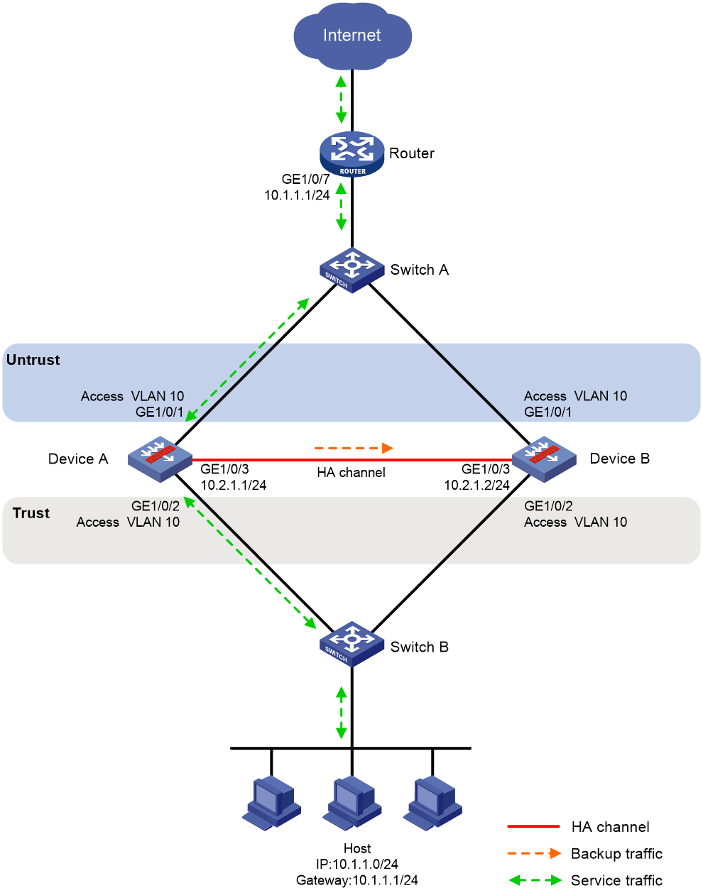
Procedure
1. Verify that Device A and Device B have software and hardware environment consistency.
2. Configure Switch A:
|
|
NOTE: This step only provides the brief configuration procedure. |
# Create VLAN 10.
# Configure the interfaces attached to the HA group and the router to operate at Layer 2. Assign them to VLAN 10 as access interfaces.
3. Configure Switch B:
|
|
NOTE: This step only provides the brief configuration procedure. |
# Create VLAN 10.
# Configure the interfaces attached to the HA group and the host to operate at Layer 2. Assign them to VLAN 10 as access interfaces.
4. Configure Device A:
a. Configure VLANs.
# Configure the uplink and downlink interfaces to operate at Layer 2.
<DeviceA> system-view
[DeviceA] interface range gigabitethernet 1/0/1 to gigabitethernet 1/0/2
[DeviceA-if-range] port link-mode bridge
[DeviceA-if-range] quit
# Assign the uplink and downlink interfaces to VLAN 10.
[DeviceA] vlan 10
[DeviceA-vlan10] port gigabitethernet 1/0/1
[DeviceA-vlan10] port gigabitethernet 1/0/2
[DeviceA-vlan10] quit
b. Assign an IP address to GigabitEthernet 1/0/3.
[DeviceA] interface gigabitethernet 1/0/3
[DeviceA-GigabitEthernet1/0/3] ip address 10.2.1.1 255.255.255.0
[DeviceA-GigabitEthernet1/0/3] quit
# Assign IP addresses to other interfaces in the same way. (Details not shown.)
c. Add interfaces to security zones.
[DeviceA] security-zone name untrust
[DeviceA-security-zone-Untrust] import interface gigabitethernet 1/0/1 vlan 10
[DeviceA-security-zone-Untrust] quit
[DeviceA] security-zone name trust
[DeviceA-security-zone-Trust] import interface gigabitethernet 1/0/2 vlan 10
[DeviceA-security-zone-Trust] quit
d. Configure a rule named trust-untrust to permit the packets from 10.1.1.0/24 to the Internet.
Perform this task only on the primary device. After the HA group is set up, the secondary device automatically synchronizes its security policy configuration with the primary device.
[DeviceA] security-policy ip
[DeviceA-security-policy-ip] rule name trust-untrust
[DeviceA-security-policy-ip-3-trust-untrust] source-zone trust
[DeviceA-security-policy-ip-3-trust-untrust] destination-zone untrust
[DeviceA-security-policy-ip-3-trust-untrust] source-ip-subnet 10.1.1.0 24
[DeviceA-security-policy-ip-3-trust-untrust] action pass
[DeviceA-security-policy-ip-3-trust-untrust] quit
[DeviceA-security-policy-ip] quit
e. Configure HA group settings.
# Set up an HA group.
[DeviceA] remote-backup group
[DeviceA-remote-backup-group] remote-ip 10.2.1.2
[DeviceA-remote-backup-group] local-ip 10.2.1.1
[DeviceA-remote-backup-group] data-channel interface gigabitethernet 1/0/3
[DeviceA-remote-backup-group] device-role primary
RBM_P[DeviceA-remote-backup-group] undo backup-mode
RBM_P[DeviceA-remote-backup-group] hot-backup enable
RBM_P[DeviceA-remote-backup-group] configuration auto-sync enable
RBM_P[DeviceA-remote-backup-group] configuration sync-check interval 12
# Configure the HA group to monitor the status of VLAN 10.
RBM_P[DeviceA-remote-backup-group] track vlan 10
RBM_P[DeviceA-remote-backup-group] quit
f. Configure security services on Device A. (Details not shown.)
5. Configure Device B:
a. Configure VLANs.
# Configure the uplink and downlink interfaces to operate at Layer 2.
<DeviceB> system-view
[DeviceB] interface range gigabitethernet 1/0/1 to gigabitethernet 1/0/2
[DeviceB-if-range] port link-mode bridge
[DeviceB-if-range] quit
# Assign the uplink and downlink interfaces to VLAN 10.
[DeviceB] vlan 10
[DeviceB-vlan10] port gigabitethernet 1/0/1
[DeviceB-vlan10] port gigabitethernet 1/0/2
[DeviceB-vlan10] quit
b. Assign an IP address to GigabitEthernet 1/0/3.
[DeviceB] interface gigabitethernet 1/0/3
[DeviceB-GigabitEthernet1/0/3] ip address 10.2.1.2 255.255.255.0
[DeviceB-GigabitEthernet1/0/3] quit
# Assign IP addresses to other interfaces in the same way. (Details not shown.)
c. Add interfaces to security zones.
[DeviceB] security-zone name untrust
[DeviceB-security-zone-Untrust] import interface gigabitethernet 1/0/1 vlan 10
[DeviceB-security-zone-Untrust] quit
[DeviceB] security-zone name trust
[DeviceB-security-zone-Trust] import interface gigabitethernet 1/0/2 vlan 10
[DeviceB-security-zone-Trust] quit
d. Configure HA group settings.
# Set up an HA group.
[DeviceB] remote-backup group
[DeviceB-remote-backup-group] remote-ip 10.2.1.1
[DeviceB-remote-backup-group] local-ip 10.2.1.2
[DeviceB-remote-backup-group] data-channel interface gigabitethernet 1/0/3
[DeviceB-remote-backup-group] device-role secondary
RBM_S[DeviceB-remote-backup-group] undo backup-mode
RBM_S[DeviceB-remote-backup-group] hot-backup enable
RBM_S[DeviceB-remote-backup-group] configuration auto-sync enable
RBM_S[DeviceB-remote-backup-group] configuration sync-check interval 12
# Configure the HA group to monitor the state of VLAN 10.
RBM_S[DeviceB-remote-backup-group] track vlan 10
RBM_S[DeviceB-remote-backup-group] quit
6. On the host, specify 10.1.1.1 as the default gateway. (Details not shown.)
Verifying the configuration
1. Verify that the HA channels have been set up on Device A.
RBM_P[DeviceA] display remote-backup-group status
Remote backup group information:
Backup mode: Active/standby
Device management role: Primary
Device running status: Active
Data channel interface: GigabitEthernet1/0/3
Local IP: 10.2.1.1
Remote IP: 10.2.1.2 Destination port: 60064
Control channel status: Connected
Keepalive interval: 1s
Keepalive count: 10
Configuration consistency check interval: 12 hour
Configuration consistency check result: Not Performed
Configuration backup status: Auto sync enabled
Session backup status: Hot backup enabled
Delay-time: 0 min
Uptime since last switchover: 0 days, 3 hours, 11 minutes
Switchover records:
Time Status change Cause
2021-06-22 13:33:33 Initial to Active Interface status changed
2. Verify that the HA channels have been set up on Device B.
RBM_S[DeviceB] display remote-backup-group status
Remote backup group information:
Backup mode: Active/standby
Device management role: Secondary
Device running status: Standby
Data channel interface: GigabitEthernet1/0/3
Local IP: 10.2.1.2
Remote IP: 10.2.1.1 Destination port: 60064
Control channel status: Connected
Keepalive interval: 1s
Keepalive count: 10
Configuration consistency check interval: 12 hour
Configuration consistency check result: Not Performed
Configuration backup status: Auto sync enabled
Session backup status: Hot backup enabled
Delay-time: 0 min
Uptime since last switchover: 0 days, 3 hours, 11 minutes
Switchover records:
Time Status change Cause
2021-06-22 13:33:33 Initial to Active Interface status changed
Example: Configuring a transparent in-path HA group in dual-active mode
Network configuration
As shown in Figure 24, set up a transparent in-path HA group at the border between the Internet and the internal network of an enterprise to ensure service continuity.
· Configure the HA group to operate in dual-active mode.
· Connect Router A and Router B to Layer 2 interfaces of the HA group.
· Configure Device A and Device B to load share traffic.
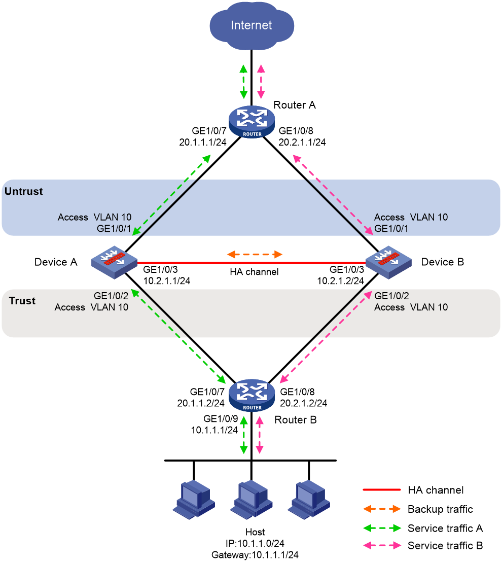
Procedure
1. Verify that Device A and Device B have software and hardware environment consistency.
2. Configure OSPF on Router A for the host to access the Internet and for Device A and Device B to load share the traffic sent to the host.
3. Configure OSPF on Router B for the host to access the Internet and for Device A and Device B to load share the traffic sent to the Internet.
4. Configure Device A:
a. Configure VLANs.
# Configure the uplink and downlink interfaces to operate at Layer 2.
<DeviceA> system-view
[DeviceA] interface range gigabitethernet 1/0/1 to gigabitethernet 1/0/2
[DeviceA-if-range] port link-mode bridge
[DeviceA-if-range] quit
# Assign the uplink and downlink interfaces to VLAN 10.
[DeviceA] vlan 10
[DeviceA-vlan10] port gigabitethernet 1/0/1
[DeviceA-vlan10] port gigabitethernet 1/0/2
[DeviceA-vlan10] quit
b. Assign an IP address to GigabitEthernet 1/0/3.
[DeviceA] interface GigabitEthernet 1/0/3
[DeviceA-GigabitEthernet1/0/3] ip address 10.2.1.1 255.255.255.0
[DeviceA-GigabitEthernet1/0/3] quit
# Assign IP addresses to other interfaces in the same way. (Details not shown.)
c. Add interfaces to security zones.
[DeviceA] security-zone name untrust
[DeviceA-security-zone-Untrust] import interface gigabitethernet 1/0/1 vlan 10
[DeviceA-security-zone-Untrust] quit
[DeviceA] security-zone name trust
[DeviceA-security-zone-Trust] import interface gigabitethernet 1/0/2 vlan 10
[DeviceA-security-zone-Trust] quit
d. Configure a security policy.
Perform this task only on the primary device. After the HA group is set up, the secondary device automatically synchronizes its security policy configuration with the primary device.
# Configure a rule named trust-untrust to permit the packets from 10.1.1.0/24 to the Internet.
[DeviceA] security-policy ip
[DeviceA-security-policy-ip] rule name trust-untrust
[DeviceA-security-policy-ip-3-trust-untrust] source-zone trust
[DeviceA-security-policy-ip-3-trust-untrust] destination-zone untrust
[DeviceA-security-policy-ip-3-trust-untrust] source-ip-subnet 10.1.1.0 24
[DeviceA-security-policy-ip-3-trust-untrust] action pass
[DeviceA-security-policy-ip-3-trust-untrust] quit
# Configure rules to permit OSPF protocol packets.
[DeviceA-security-policy-ip] rule name ospf1
[DeviceA-security-policy-ip-4-ospf1] source-zone trust
[DeviceA-security-policy-ip-4-ospf1] destination-zone untrust
[DeviceA-security-policy-ip-4-ospf1] service ospf
[DeviceA-security-policy-ip-4-ospf1] action pass
[DeviceA-security-policy-ip-4-ospf1] quit
[DeviceA-security-policy-ip] rule name ospf2
[DeviceA-security-policy-ip-5-ospf2] source-zone untrust
[DeviceA-security-policy-ip-5-ospf2] destination-zone trust
[DeviceA-security-policy-ip-5-ospf2] service ospf
[DeviceA-security-policy-ip-5-ospf2] action pass
[DeviceA-security-policy-ip-5-ospf2] quit
[DeviceA-security-policy-ip] quit
e. Configure HA group settings.
# Set up an HA group.
[DeviceA] remote-backup group
[DeviceA-remote-backup-group] remote-ip 10.2.1.2
[DeviceA-remote-backup-group] local-ip 10.2.1.1
[DeviceA-remote-backup-group] data-channel interface gigabitethernet 1/0/3
[DeviceA-remote-backup-group] device-role primary
RBM_P[DeviceA-remote-backup-group] backup-mode dual-active
RBM_P[DeviceA-remote-backup-group] hot-backup enable
RBM_P[DeviceA-remote-backup-group] configuration auto-sync enable
RBM_P[DeviceA-remote-backup-group] configuration sync-check interval 12
RBM_P[DeviceA-remote-backup-group] delay-time 1
# Configure the HA group to monitor the status of GigabitEthernet 1/0/1 and GigabitEthernet 1/0/2.
RBM_P[DeviceA-remote-backup-group] track interface gigabitethernet 1/0/1
RBM_P[DeviceA-remote-backup-group] track interface gigabitethernet 1/0/2
RBM_P[DeviceA-remote-backup-group] quit
f. Configure security services on Device A. (Details not shown.)
5. Configure Device B:
a. Configure VLANs.
# Configure the uplink and downlink interfaces to operate at Layer 2.
<DeviceB> system-view
[DeviceB] interface range gigabitethernet 1/0/1 to gigabitethernet 1/0/2
[DeviceB-if-range] port link-mode bridge
[DeviceB-if-range] quit
# Assign the uplink and downlink interfaces to VLAN 10.
[DeviceB] vlan 10
[DeviceB-vlan10] port gigabitethernet 1/0/1
[DeviceB-vlan10] port gigabitethernet 1/0/2
[DeviceB-vlan10] quit
b. Assign an IP address to GigabitEthernet 1/0/3.
[DeviceB] interface gigabitethernet 1/0/3
[DeviceB-GigabitEthernet1/0/3] ip address 10.2.1.2 255.255.255.0
[DeviceB-GigabitEthernet1/0/3] quit
# Assign IP addresses to other interfaces in the same way. (Details not shown.)
c. Add interfaces to security zones.
[DeviceB] security-zone name untrust
[DeviceB-security-zone-Untrust] import interface gigabitethernet 1/0/1 vlan 10
[DeviceB-security-zone-Untrust] quit
[DeviceB] security-zone name trust
[DeviceB-security-zone-Trust] import interface gigabitethernet 1/0/2 vlan 10
[DeviceB-security-zone-Trust] quit
d. Configure HA group settings.
# Set up an HA group.
[DeviceB] remote-backup group
[DeviceB-remote-backup-group] remote-ip 10.2.1.1
[DeviceB-remote-backup-group] local-ip 10.2.1.2
[DeviceB-remote-backup-group] data-channel interface gigabitethernet 1/0/3
[DeviceB-remote-backup-group] device-role secondary
RBM_S[DeviceB-remote-backup-group] backup-mode dual-active
RBM_S[DeviceB-remote-backup-group] hot-backup enable
RBM_S[DeviceB-remote-backup-group] configuration auto-sync enable
RBM_S[DeviceB-remote-backup-group] delay-time 1
RBM_S[DeviceB-remote-backup-group] configuration sync-check interval 12
# Configure the HA group to monitor the status of GigabitEthernet 1/0/1 and GigabitEthernet 1/0/2.
RBM_S[DeviceB-remote-backup-group] track interface gigabitethernet 1/0/1
RBM_S[DeviceB-remote-backup-group] track interface gigabitethernet 1/0/2
RBM_S[DeviceB-remote-backup-group] quit
6. On the host, specify 10.1.1.1 as the default gateway. (Details not shown.)
Verifying the configuration
1. Verify that the HA channels have been set up on Device A.
RBM_P[DeviceA] display remote-backup-group status
Remote backup group information:
Backup mode: Dual-active
Device management role: Primary
Device running status: Active
Data channel interface: GigabitEthernet1/0/3
Local IP: 10.2.1.1
Remote IP: 10.2.1.2 Destination port: 60064
Control channel status: Connected
Keepalive interval: 1s
Keepalive count: 10
Configuration consistency check interval: 12 hour
Configuration consistency check result: Not Performed
Configuration backup status: Auto sync enabled
Session backup status: Hot backup enabled
Delay-time: 1 min
Uptime since last switchover: 0 days, 3 hours, 11 minutes
Switchover records:
Time Status change Cause
2021-06-22 13:33:33 Initial to Active Interface status changed
2. Verify that the HA channels have been set up on Device B.
RBM_S[DeviceB] display remote-backup-group status
Remote backup group information:
Backup mode: Dual-active
Device management role: Secondary
Device running status: Active
Data channel interface: GigabitEthernet1/0/3
Local IP: 10.2.1.2
Remote IP: 10.2.1.1 Destination port: 60064
Control channel status: Connected
Keepalive interval: 1s
Keepalive count: 10
Configuration consistency check interval: 12 hour
Configuration consistency check result: Not Performed
Configuration backup status: Auto sync enabled
Session backup status: Hot backup enabled
Delay-time: 1 min
Uptime since last switchover: 0 days, 3 hours, 11 minutes
Switchover records:
Time Status change Cause
2021-06-22 13:33:33 Initial to Active Interface status changed
Example: Configuring interface-based NAT on the HA group in active/standby mode in collaboration with VRRP
Network configuration
As shown in Figure 25, set up the HA group at the border between the Internet and the internal network of an enterprise to ensure service continuity.
· Configure the HA group to collaborate with VRRP.
· Configure the HA group to operate in active/standby mode.
· Configure Device A and Device B as the primary device and the secondary device, respectively.
· Configure dynamic NAT to translate the private IP addresses in the internal network into public IP addresses 2.1.1.1 through 2.1.1.10.

Procedure
1. Set up the HA group as described in "Example: Configuring the HA group in active/standby mode in collaboration with VRRP."
2. Configure dynamic NAT on Device A (primary):
# Create NAT address group 1 and add address range 2.1.1.5 to 2.1.1.10. Associate NAT address group 1 with VRRP group 1.
RBM_P<DeviceA> system-view
RBM_P[DeviceA] nat address-group 1
RBM_P[DeviceA-address-group-1] address 2.1.1.5 2.1.1.10
RBM_P[DeviceA-address-group-1] vrrp vrid 1
RBM_P[DeviceA-address-group-1] quit
# Configure outbound dynamic NAT to use NAT address group 1 for address translation on GigabitEthernet 1/0/1.
RBM_P[DeviceA] interface gigabitethernet 1/0/1
RBM_P[DeviceA-GigabitEthernet1/0/1] nat outbound address-group 1
RBM_P[DeviceA-GigabitEthernet1/0/1] quit
Verifying the configuration
# Verify that the host can communicate with the Internet. (Details not shown.)
# Verify that Device A has generated a NAT session entry.
RBM_P[DeviceA] display nat session verbose
Slot 1:
Initiator:
Source IP/port: 10.1.1.10/52082
Destination IP/port: 202.38.1.10/80
DS-Lite tunnel peer: -
VPN instance/VLAN ID/Inline ID: -/-/-
Protocol: TCP(6)
Inbound interface: GigabitEthernet1/0/2
Source security zone: Trust
Responder:
Source IP/port: 202.38.1.10/80
Destination IP/port: 2.1.1.5/1036
DS-Lite tunnel peer: -
VPN instance/VLAN ID/Inline ID: -/-/-
Protocol: TCP(6)
Inbound interface: GigabitEthernet1/0/1
Source security zone: Untrust
State: TCP_ESTABLISHED
Application: HTTP
Rule ID: 2
Rule name: 3
Start time: 2019-1-29 16:16:59 TTL: 9995s
Initiator->Responder: 551 packets 32547 bytes
Responder->Initiator: 956 packets 1385514 bytes
Total sessions found: 1
Example: Configuring interface-based NAT on the HA group in dual-active mode in collaboration with VRRP
Network configuration
As shown in Figure 26, set up the HA group at the border between the Internet and the internal network of an enterprise to ensure service continuity.
· Configure the HA group to collaborate with VRRP.
· Configure the HA group to operate in dual-active mode.
· Configure Device A and Device B to load share traffic.
· Configure dynamic NAT to translate the private IP addresses in the internal network into public IP addresses 2.1.1.1 through 2.1.1.10.
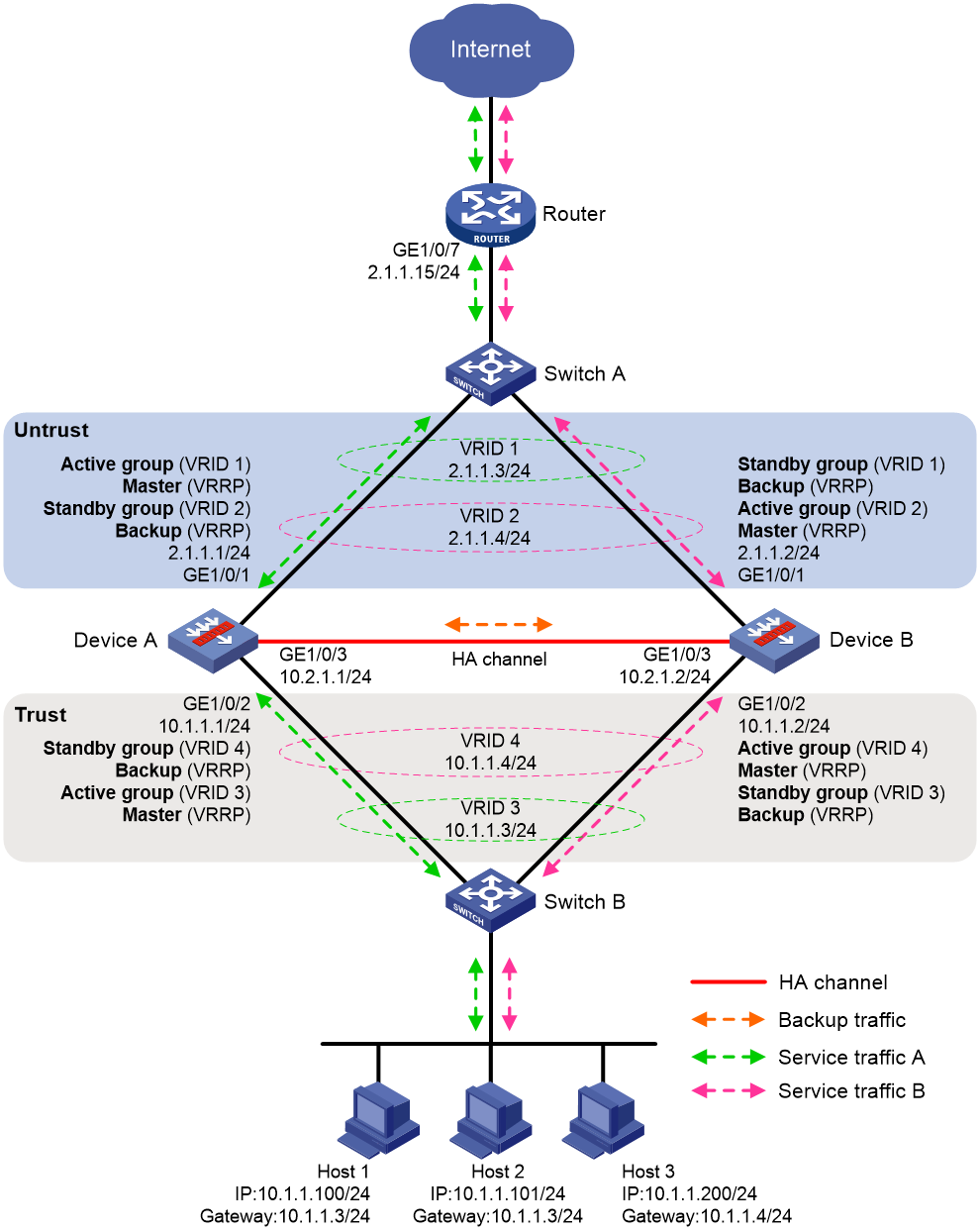
Procedure
1. Set up the HA group as described in "Example: Configuring the HA group in dual-active mode in collaboration with VRRP".
2. Configure dynamic NAT on Device A (primary):
# Create NAT address group 1 and add address range 2.1.1.5 to 2.1.1.7. Associate NAT address group 1 with VRRP group 1.
RBM_P<DeviceA> system-view
RBM_P[DeviceA] nat address-group 1
RBM_P[DeviceA-address-group-1] address 2.1.1.5 2.1.1.7
RBM_P[DeviceA-address-group-1] vrrp vrid 1
RBM_P[DeviceA-address-group-1] quit
# Create NAT address group 2 and add address range 2.1.1.8 to 2.1.1.10. Associate NAT address group 2 with VRRP group 2.
RBM_P[DeviceA] nat address-group 2
RBM_P[DeviceA-address-group-2] address 2.1.1.8 2.1.1.10
RBM_P[DeviceA-address-group-2] vrrp vrid 2
RBM_P[DeviceA-address-group-2] quit
# Configure ACL 3000 to permit packets from 10.1.1.1/25. Configure ACL 3001 to permit packets from 10.1.1.129/25.
RBM_P[DeviceA] acl advanced 3000
RBM_P[DeviceA-ipv4-adv-3000] rule permit ip source 10.1.1.1 0.0.0.127
RBM_P[DeviceA-ipv4-adv-3000] quit
RBM_P[DeviceA] acl advanced 3001
RBM_P[DeviceA-ipv4-adv-3001] rule permit ip source 10.1.1.129 0.0.0.127
RBM_P[DeviceA-ipv4-adv-3001] quit
# Configure outbound dynamic NAT on GigabitEthernet 1/0/1. The source IP addresses of the packets permitted by ACL 3000 are translated into the addresses in NAT address group 1. The source IP addresses of the packets permitted by ACL 3001 are translated into the addresses in NAT address group 2.
RBM_P[DeviceA] interface gigabitethernet 1/0/1
RBM_P[DeviceA-GigabitEthernet1/0/1] nat outbound 3000 address-group 1
RBM_P[DeviceA-GigabitEthernet1/0/1] nat outbound 3001 address-group 2
RBM_P[DeviceA-GigabitEthernet1/0/1] quit
Verifying the configuration
# Verify that Host 1 can communicate with the Internet. (Details not shown.)
# Verify that Device A has generated a NAT session entry.
RBM_P[DeviceA] display nat session verbose
Slot 1:
Initiator:
Source IP/port: 10.1.1.100/52082
Destination IP/port: 202.38.1.10/80
DS-Lite tunnel peer: -
VPN instance/VLAN ID/Inline ID: -/-/-
Protocol: TCP(6)
Inbound interface: GigabitEthernet1/0/2
Source security zone: Trust
Responder:
Source IP/port: 202.38.1.10/80
Destination IP/port: 2.1.1.5/1036
DS-Lite tunnel peer: -
VPN instance/VLAN ID/Inline ID: -/-/-
Protocol: TCP(6)
Inbound interface: GigabitEthernet1/0/1
Source security zone: Untrust
State: TCP_ESTABLISHED
Application: HTTP
Rule ID: 2
Rule name: 3
Start time: 2019-1-29 16:16:59 TTL: 9995s
Initiator->Responder: 551 packets 32547 bytes
Responder->Initiator: 956 packets 1385514 bytes
Total sessions found: 1
# Verify that Host 3 can communicate with the Internet. (Details not shown.)
# Verify that Device B has generated a NAT session entry.
RBM_S[DeviceB] display nat session verbose
Slot 1:
Initiator:
Source IP/port: 10.1.1.200/52082
Destination IP/port: 202.38.1.10/80
DS-Lite tunnel peer: -
VPN instance/VLAN ID/Inline ID: -/-/-
Protocol: TCP(6)
Inbound interface:
Source security zone: Trust
Responder:
Source IP/port: 202.38.1.10/80
Destination IP/port: 2.1.1.8/1036
DS-Lite tunnel peer: -
VPN instance/VLAN ID/Inline ID: -/-/-
Protocol: TCP(6)
Inbound interface:
Source security zone: Untrust
State: TCP_ESTABLISHED
Application: HTTP
Rule ID: 2
Rule name: 3
Start time: 2019-1-29 16:17:59 TTL: 9995s
Initiator->Responder: 551 packets 32547 bytes
Responder->Initiator: 956 packets 1385514 bytes
Total sessions found: 1
Example: Configuring global NAT on the HA group in active/standby mode in collaboration with VRRP
Network configuration
As shown in Figure 27, set up the HA group at the border between the Internet and the internal network of an enterprise to ensure service continuity.
· Configure the HA group to collaborate with VRRP.
· Configure the HA group to operate in active/standby mode.
· Configure Device A and Device B as the primary device and the secondary device, respectively.
· Configure dynamic NAT to translate the private IP addresses in the internal network into public IP addresses 2.1.1.1 through 2.1.1.10.
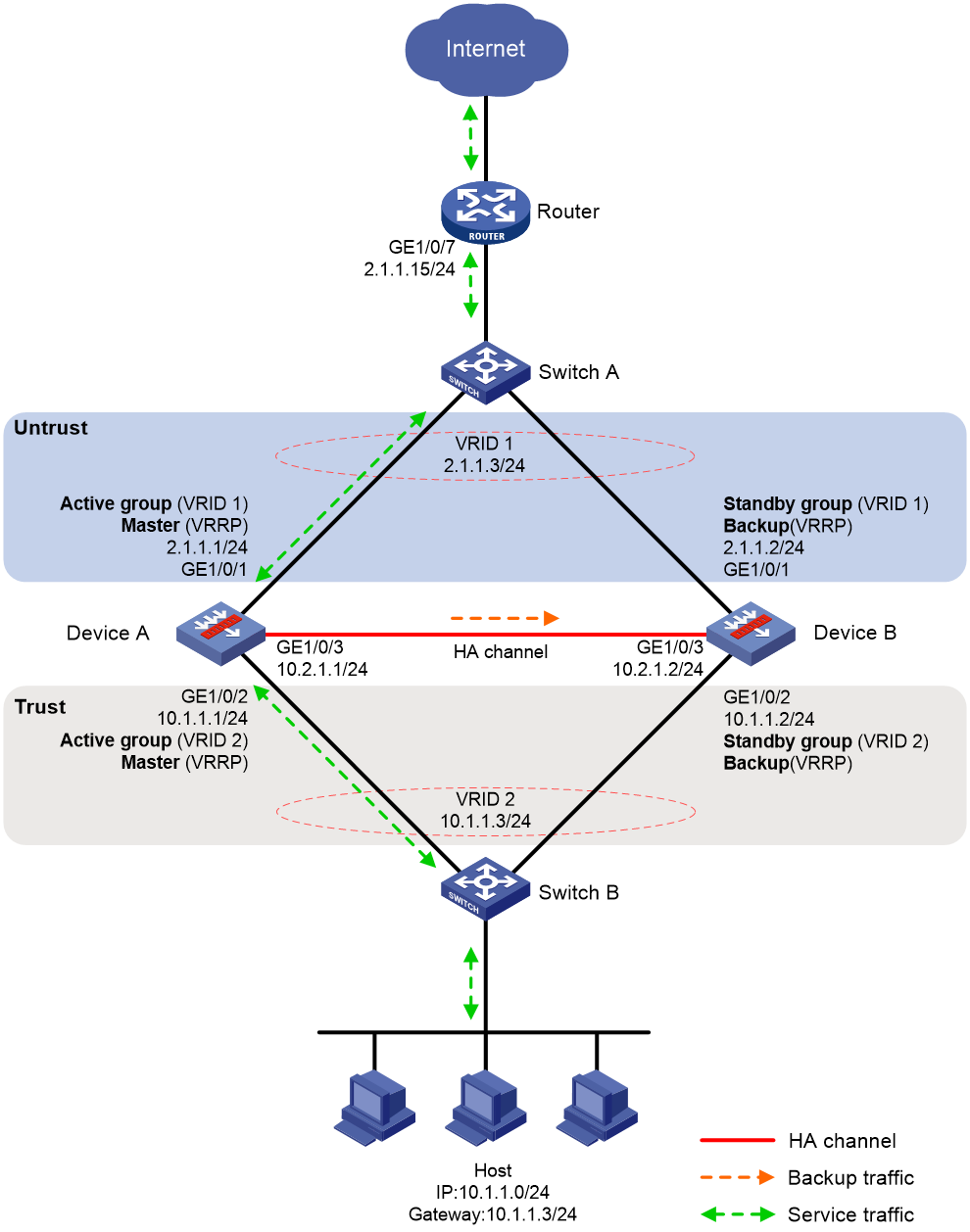
Procedure
1. Set up the HA group as described in "Example: Configuring the HA group in active/standby mode in collaboration with VRRP."
2. Configure dynamic NAT globally on Device A (primary):
# Create NAT address group 1 and add address range 2.1.1.5 to 2.1.1.10. Associate NAT address group 1 with VRRP group 1.
RBM_P<DeviceA> system-view
RBM_P[DeviceA] nat address-group 1
RBM_P[DeviceA-address-group-1] address 2.1.1.5 2.1.1.10
RBM_P[DeviceA-address-group-1] vrrp vrid 1
RBM_P[DeviceA-address-group-1] quit
# Configure a global NAT policy to use NAT address group 1 for address translation of the traffic sent from the internal network to the Internet.
RBM_P[DeviceA] nat global-policy
RBM_P[DeviceA-nat-global-policy] rule name rule1
RBM_P[DeviceA-nat-global-policy-rule1] source-zone Trust
RBM_P[DeviceA-nat-global-policy-rule1] destination-zone Untrust
RBM_P[DeviceA-nat-global-policy-rule1] source-ip subnet 10.1.1.0 24
RBM_P[DeviceA-nat-global-policy-rule1] action snat address-group 1 vrrp 1
RBM_P[DeviceA-nat-global-policy-rule1] quit
RBM_P[DeviceA-nat-global-policy] quit
Verifying the configuration
# Verify that the host can communicate with the Internet. (Details not shown.)
# Verify that Device A has generated a NAT session entry.
RBM_P[DeviceA] display nat session verbose
Slot 1:
Initiator:
Source IP/port: 10.1.1.10/52082
Destination IP/port: 202.38.1.10/80
DS-Lite tunnel peer: -
VPN instance/VLAN ID/Inline ID: -/-/-
Protocol: TCP(6)
Inbound interface: GigabitEthernet1/0/2
Source security zone: Trust
Responder:
Source IP/port: 202.38.1.10/80
Destination IP/port: 2.1.1.5/1036
DS-Lite tunnel peer: -
VPN instance/VLAN ID/Inline ID: -/-/-
Protocol: TCP(6)
Inbound interface: GigabitEthernet1/0/1
Source security zone: Untrust
State: TCP_ESTABLISHED
Application: HTTP
Rule ID: 2
Rule name: 3
Start time: 2019-1-29 16:16:59 TTL: 9995s
Initiator->Responder: 551 packets 32547 bytes
Responder->Initiator: 956 packets 1385514 bytes
Total sessions found: 1
Example: Configuring global NAT on the HA group in dual-active mode in collaboration with VRRP
Network configuration
As shown in Figure 28, set up the HA group at the border between the Internet and the internal network of an enterprise to ensure service continuity.
· Configure the HA group to collaborate with VRRP.
· Configure the HA group to operate in dual-active mode.
· Configure Device A and Device B to load share traffic.
· Configure dynamic NAT to translate the private IP addresses in the internal network into public IP addresses 2.1.1.1 through 2.1.1.10.

Procedure
1. Set up the HA group as described in "Example: Configuring the HA group in dual-active mode in collaboration with VRRP".
2. Configure dynamic NAT on Device A (primary):
# Create NAT address group 1 and add address range 2.1.1.5 to 2.1.1.7. Associate NAT address group 1 with VRRP group 1.
RBM_P<DeviceA> system-view
RBM_P[DeviceA] nat address-group 1
RBM_P[DeviceA-address-group-1] address 2.1.1.5 2.1.1.7
RBM_P[DeviceA-address-group-1] vrrp vrid 1
RBM_P[DeviceA-address-group-1] quit
# Create NAT address group 2 and add address range 2.1.1.8 to 2.1.1.10. Associate NAT address group 2 with VRRP group 2.
RBM_P[DeviceA] nat address-group 2
RBM_P[DeviceA-address-group-2] address 2.1.1.8 2.1.1.10
RBM_P[DeviceA-address-group-2] vrrp vrid 2
RBM_P[DeviceA-address-group-2] quit
# Configure global NAT rule 1 to use NAT address group 1 for address translation of the traffic sent from the 10.1.1.1/25 network to the Internet.
RBM_P[DeviceA] nat global-policy
RBM_P[DeviceA-nat-global-policy] rule name rule1
RBM_P[DeviceA-nat-global-policy-rule1] source-zone Trust
RBM_P[DeviceA-nat-global-policy-rule1] destination-zone Untrust
RBM_P[DeviceA-nat-global-policy-rule1] source-ip subnet 10.1.1.1 25
RBM_P[DeviceA-nat-global-policy-rule1] action snat address-group 1 vrrp 1
RBM_P[DeviceA-nat-global-policy-rule1] quit
# Configure global NAT rule 2 to use NAT address group 2 for address translation of the traffic sent from the 10.1.1.129/25 network to the Internet.
RBM_P[DeviceA-nat-global-policy] rule name rule2
RBM_P[DeviceA-nat-global-policy-rule2] source-zone Trust
RBM_P[DeviceA-nat-global-policy-rule2] destination-zone Untrust
RBM_P[DeviceA-nat-global-policy-rule2] source-ip subnet 10.1.1.129 25
RBM_P[DeviceA-nat-global-policy-rule2] action snat address-group 2 vrrp 2
RBM_P[DeviceA-nat-global-policy-rule2] quit
RBM_P[DeviceA-nat-global-policy] quit
Verifying the configuration
# Verify that Host 1 can communicate with the Internet. (Details not shown.)
# Verify that Device A has generated a NAT session entry.
RBM_P[DeviceA] display nat session verbose
Slot 1:
Initiator:
Source IP/port: 10.1.1.100/52082
Destination IP/port: 202.38.1.10/80
DS-Lite tunnel peer: -
VPN instance/VLAN ID/Inline ID: -/-/-
Protocol: TCP(6)
Inbound interface: GigabitEthernet1/0/2
Source security zone: Trust
Responder:
Source IP/port: 202.38.1.10/80
Destination IP/port: 2.1.1.5/1036
DS-Lite tunnel peer: -
VPN instance/VLAN ID/Inline ID: -/-/-
Protocol: TCP(6)
Inbound interface: GigabitEthernet1/0/1
Source security zone: Untrust
State: TCP_ESTABLISHED
Application: HTTP
Rule ID: 2
Rule name: 3
Start time: 2019-1-29 16:16:59 TTL: 9995s
Initiator->Responder: 551 packets 32547 bytes
Responder->Initiator: 956 packets 1385514 bytes
Total sessions found: 1
# Verify that Host 3 can communicate with the Internet. (Details not shown.)
# Verify that Device B has generated a NAT session entry.
RBM_S[DeviceB] display nat session verbose
Slot 1:
Initiator:
Source IP/port: 10.1.1.200/52082
Destination IP/port: 202.38.1.10/80
DS-Lite tunnel peer: -
VPN instance/VLAN ID/Inline ID: -/-/-
Protocol: TCP(6)
Inbound interface:
Source security zone: Trust
Responder:
Source IP/port: 202.38.1.10/80
Destination IP/port: 2.1.1.8/1036
DS-Lite tunnel peer: -
VPN instance/VLAN ID/Inline ID: -/-/-
Protocol: TCP(6)
Inbound interface:
Source security zone: Untrust
State: TCP_ESTABLISHED
Application: HTTP
Rule ID: 2
Rule name: 3
Start time: 2019-1-29 16:17:59 TTL: 9995s
Initiator->Responder: 551 packets 32547 bytes
Responder->Initiator: 956 packets 1385514 bytes
Total sessions found: 1
HA group configuration examples (IPv6)
Example: Configuring the HA group in active/standby mode in collaboration with VRRP
Network configuration
As shown in Figure 19, set up the HA group at the border between the Internet and the internal network of an enterprise to ensure service continuity.
· Configure the HA group to collaborate with VRRP.
· Configure the HA group to operate in active/standby mode.
· Configure Device A and Device B as the primary device and the secondary device, respectively.
Figure 29 Network diagram
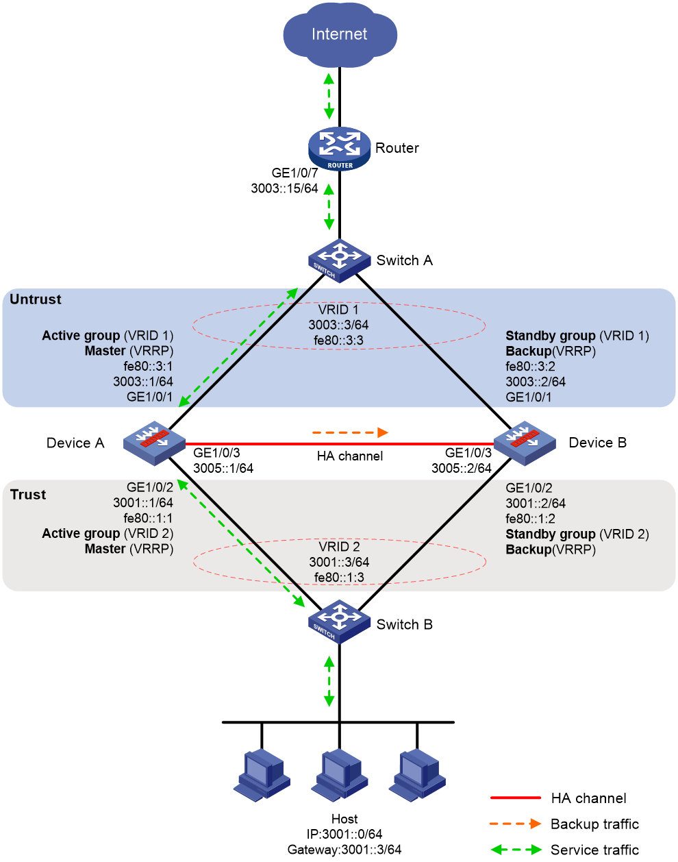
Procedure
1. Verify that Device A and Device B have software and hardware environment consistency.
2. Configure Switch A:
|
|
NOTE: This step only provides the brief configuration procedure. |
# Create VLAN 10.
# Configure the interfaces attached to the HA group and the router to operate at Layer 2. Assign them to VLAN 10 as access interfaces.
3. Configure Switch B:
|
|
NOTE: This step only provides the brief configuration procedure. |
# Create VLAN 10.
# Configure the interfaces attached to the HA group and the host to operate at Layer 2. Assign them to VLAN 10 as access interfaces.
4. Configure the router:
|
|
NOTE: This step only provides the brief configuration procedure. |
# Assign 3003::15/64 to GigabitEthernet 1/0/7.
# Configure routes as follows:
¡ Specify 3003::3/64 (virtual IP address of VRRP group 1) as the next hop of the routes to the internal network.
¡ Specify the IP address of the peer interface attached to the traffic outgoing interface as the next hop of the route to the Internet.
5. Configure Device A:
a. Assign IP addresses to interfaces.
<DeviceA> system-view
[DeviceA] interface gigabitethernet 1/0/1
[DeviceA-GigabitEthernet1/0/1] ipv6 address 3003::1/64
[DeviceA-GigabitEthernet1/0/1] ipv6 address fe80::3:1 link-local
[DeviceA-GigabitEthernet1/0/1] quit
[DeviceA] interface gigabitethernet 1/0/2
[DeviceA-GigabitEthernet1/0/2] ipv6 address 3001::1/64
[DeviceA-GigabitEthernet1/0/2] ipv6 address fe80::1:1 link-local
[DeviceA-GigabitEthernet1/0/2] undo ipv6 nd ra halt
[DeviceA-GigabitEthernet1/0/2] quit
[DeviceA] interface gigabitethernet 1/0/3
[DeviceA-GigabitEthernet1/0/3] ipv6 address 3005::1/64
[DeviceA-GigabitEthernet1/0/3] ipv6 address auto link-local
[DeviceA-GigabitEthernet1/0/3] quit
b. Add interfaces to security zones.
[DeviceA] security-zone name untrust
[DeviceA-security-zone-Untrust] import interface gigabitethernet 1/0/1
[DeviceA-security-zone-Untrust] quit
[DeviceA] security-zone name trust
[DeviceA-security-zone-Trust] import interface gigabitethernet 1/0/2
[DeviceA-security-zone-Trust] quit
c. Configure settings for routing. This example configures a static route, and the next hop in the route is 3003::15.
[DeviceA] ipv6 route-static 0::0 0 3003::15
d. Configure a security policy.
Perform this task only on the primary device. After the HA group is set up, the secondary device automatically synchronizes its security policy configuration with the primary device.
# Configure security policy rule named trust-untrust to permit the packets from 3001::0/64 to the Internet.
[DeviceA] security-policy ipv6
[DeviceA-security-policy-ipv6] rule name trust-untrust
[DeviceA-security-policy-ipv6-3-trust-untrust] source-zone trust
[DeviceA-security-policy-ipv6-3-trust-untrust] destination-zone untrust
[DeviceA-security-policy-ipv6-3-trust-untrust] source-ip-subnet 3001::0 64
[DeviceA-security-policy-ipv6-3-trust-untrust] action pass
[DeviceA-security-policy-ipv6-3-trust-untrust] quit
# Configure rules to permit VRRP protocol packets. When the HA channel is disconnected, Device A and Device B can exchange VRRP protocol packets to elect a VRRP master.
[DeviceA-security-policy-ipv6] rule name vrrp1
[DeviceA-security-policy-ipv6-4-vrrp1] source-zone trust
[DeviceA-security-policy-ipv6-4-vrrp1] destination-zone local
[DeviceA-security-policy-ipv6-4-vrrp1] service vrrp
[DeviceA-security-policy-ipv6-4-vrrp1] action pass
[DeviceA-security-policy-ipv6-4-vrrp1] quit
[DeviceA-security-policy-ipv6] rule name vrrp2
[DeviceA-security-policy-ipv6-5-vrrp2] source-zone local
[DeviceA-security-policy-ipv6-5-vrrp2] destination-zone trust
[DeviceA-security-policy-ipv6-5-vrrp2] service vrrp
[DeviceA-security-policy-ipv6-5-vrrp2] action pass
[DeviceA-security-policy-ipv6-5-vrrp2] quit
[DeviceA-security-policy-ipv6] rule name vrrp3
[DeviceA-security-policy-ipv6-6-vrrp3] source-zone untrust
[DeviceA-security-policy-ipv6-6-vrrp3] destination-zone local
[DeviceA-security-policy-ipv6-6-vrrp3] service vrrp
[DeviceA-security-policy-ipv6-6-vrrp3] action pass
[DeviceA-security-policy-ipv6-6-vrrp3] quit
[DeviceA-security-policy-ipv6] rule name vrrp4
[DeviceA-security-policy-ipv6-7-vrrp4] source-zone local
[DeviceA-security-policy-ipv6-7-vrrp4] destination-zone untrust
[DeviceA-security-policy-ipv6-7-vrrp4] service vrrp
[DeviceA-security-policy-ipv6-7-vrrp4] action pass
[DeviceA-security-policy-ipv6-7-vrrp4] quit
[DeviceA-security-policy-ipv6] quit
e. Configure HA group settings.
# Set up an HA group.
[DeviceA] remote-backup group
[DeviceA-remote-backup-group] remote-ipv6 3005::2
[DeviceA-remote-backup-group] local-ipv6 3005::1
[DeviceA-remote-backup-group] data-channel interface gigabitethernet 1/0/3
[DeviceA-remote-backup-group] device-role primary
RBM_P[DeviceA-remote-backup-group] undo backup-mode
RBM_P[DeviceA-remote-backup-group] hot-backup enable
RBM_P[DeviceA-remote-backup-group] configuration auto-sync enable
RBM_P[DeviceA-remote-backup-group] configuration sync-check interval 12
RBM_P[DeviceA-remote-backup-group] quit
# Create VRRP groups and associate them with the HA group.
RBM_P[DeviceA] interface gigabitethernet 1/0/1
RBM_P[DeviceA-GigabitEthernet1/0/1] vrrp ipv6 vrid 1 virtual-ip fe80::3:3 link-local active
RBM_P[DeviceA-GigabitEthernet1/0/1] vrrp ipv6 vrid 1 virtual-ip 3003::3
RBM_P[DeviceA-GigabitEthernet1/0/1] quit
RBM_P[DeviceA] interface gigabitethernet 1/0/2
RBM_P[DeviceA-GigabitEthernet1/0/2] vrrp ipv6 vrid 1 virtual-ip fe80::1:3 link-local active
RBM_P[DeviceA-GigabitEthernet1/0/2] vrrp ipv6 vrid 1 virtual-ip 3001::3
RBM_P[DeviceA-GigabitEthernet1/0/2] quit
f. Configure security services on Device A. (Details not shown.)
6. Configure Device B:
a. Assign IP addresses to interfaces.
<DeviceB> system-view
[DeviceB] interface gigabitethernet 1/0/1
[DeviceB-GigabitEthernet1/0/1] ipv6 address 3003::2/64
[DeviceB-GigabitEthernet1/0/1] ipv6 address fe80::3:2 link-local
[DeviceB-GigabitEthernet1/0/1] quit
[DeviceB] interface gigabitethernet 1/0/2
[DeviceB-GigabitEthernet1/0/2] ipv6 address 3001::2/64
[DeviceB-GigabitEthernet1/0/2] ipv6 address fe80::1:2 link-local
[DeviceB-GigabitEthernet1/0/2] undo ipv6 nd ra halt
[DeviceB-GigabitEthernet1/0/2] quit
[DeviceB] interface gigabitethernet 1/0/3
[DeviceB-GigabitEthernet1/0/3] ipv6 address 3005::2/64
[DeviceB-GigabitEthernet1/0/3] ipv6 address auto link-local
[DeviceB-GigabitEthernet1/0/3] quit
b. Add interfaces to security zones.
[DeviceB] security-zone name untrust
[DeviceB-security-zone-Untrust] import interface gigabitethernet 1/0/1
[DeviceB-security-zone-Untrust] quit
[DeviceB] security-zone name trust
[DeviceB-security-zone-Trust] import interface gigabitethernet 1/0/2
[DeviceB-security-zone-Trust] quit
c. Configure settings for routing. This example configures a static route, and the next hop in the route is 3003::15.
[DeviceB] ipv6 route-static 0::0 0 3003::15
d. Configure HA group settings.
# Set up an HA group.
[DeviceB] remote-backup group
[DeviceB-remote-backup-group] remote-ipv6 3005::1
[DeviceB-remote-backup-group] local-ipv6 3005::2
[DeviceB-remote-backup-group] data-channel interface gigabitethernet 1/0/3
[DeviceB-remote-backup-group] device-role secondary
RBM_S[DeviceB-remote-backup-group] undo backup-mode
RBM_S[DeviceB-remote-backup-group] hot-backup enable
RBM_S[DeviceB-remote-backup-group] configuration auto-sync enable
RBM_S[DeviceB-remote-backup-group] configuration sync-check interval 12
RBM_S[DeviceB-remote-backup-group] quit
# Create VRRP groups and associate them with the HA group.
RBM_S[DeviceB] interface gigabitethernet 1/0/1
RBM_S[DeviceB-GigabitEthernet1/0/1] vrrp ipv6 vrid 1 virtual-ip fe80::3:3 link-local standby
RBM_S[DeviceB-GigabitEthernet1/0/1] vrrp ipv6 vrid 1 virtual-ip 3003::3
RBM_S[DeviceB-GigabitEthernet1/0/1] quit
RBM_S[DeviceB] interface gigabitethernet 1/0/2
RBM_S[DeviceB-GigabitEthernet1/0/2] vrrp ipv6 vrid 1 virtual-ip fe80::1:3 link-local standby
RBM_S[DeviceB-GigabitEthernet1/0/2] vrrp ipv6 vrid 1 virtual-ip 3001::3
RBM_S[DeviceB-GigabitEthernet1/0/2] quit
7. On the host, specify 3001::3 (virtual IP address of VRRP group 2) as the default gateway. (Details not shown.)
Verifying the configuration
1. Verify the configuration on Device A:
# Verify that the HA channels have been set up.
RBM_P[DeviceA] display remote-backup-group status
Remote backup group information:
Backup mode: Active/standby
Device management role: Primary
Device running status: Active
Data channel interface: GigabitEthernet1/0/3
Keepalive interval: 1s
Keepalive count: 10
Configuration consistency check interval: 12 hour
Configuration consistency check result: Not Performed
Configuration backup status: Auto sync enabled
Session backup status: Hot backup enabled
Delay-time: 0 min
Uptime since last switchover: 0 days, 3 hours, 11 minutes
Switchover records:
Time Status change Cause
2021-06-22 13:33:33 Initial to Active Interface status changed
# Verify that Device A is the master in all VRRP groups.
RBM_P[DeviceA] display vrrp ipv6
IPv6 Virtual Router Information:
Running mode : Standard
RBM control channel is established
IPv6 VRRP active group status : Master
IPv6 VRRP standby group status: Master
Total number of virtual routers : 2
Interface VRID State Running Adver Auth Virtual
Pri Timer Type IP
---------------------------------------------------------------------
GE1/0/1 1 Master 100 100 None FE80::3:3
GE1/0/2 1 Master 100 100 None FE80::1:3
# Enable logging for the security policy that permits communication between security zones Trust and Untrust. Verity that Device A generates log messages when the host communicates with the Internet. (Details not shown.)
2. Verify the configuration on Device B:
# Verify that the HA channels have been set up.
RBM_S[DeviceB] display remote-backup-group status
Remote backup group information:
Backup mode: Active/standby
Device management role: Secondary
Device running status: Standby
Data channel interface: GigabitEthernet1/0/3
Local IPv6: 3005::2
Remote IPv6: 3005::1 Destination port: 60064
Control channel status: Connected
Keepalive interval: 1s
Keepalive count: 10
Configuration consistency check interval: 12 hour
Configuration consistency check result: Not Performed
Configuration backup status: Auto sync enabled
Session backup status: Hot backup enabled
Delay-time: 0 min
Uptime since last switchover: 0 days, 3 hours, 11 minutes
Switchover records:
Time Status change Cause
2021-06-22 13:33:33 Initial to Active Interface status changed
# Verify that Device A is the backup in all VRRP groups.
RBM_S[DeviceB] display vrrp ipv6
IPv6 Virtual Router Information:
Running mode : Standard
RBM control channel is established
IPv6 VRRP active group status : Backup
IPv6 VRRP standby group status: Backup
Total number of virtual routers : 2
Interface VRID State Running Adver Auth Virtual
Pri Timer Type IP
---------------------------------------------------------------------
GE1/0/1 1 Backup 100 100 None FE80::3:3
GE1/0/2 1 Backup 100 100 None FE80::1:3
# Enable logging for the security policy that permits communication between security zones Trust and Untrust. Verity that Device B does not generate log messages when the host communicates with the Internet. (Details not shown.)
Example: Configuring the HA group in dual-active mode in collaboration with a routing protocol
Network configuration
As shown in Figure 22, set up the HA group at the border between the Internet and the internal network of an enterprise to ensure service continuity.
· Configure the HA group to collaborate with OSPFv3.
· Configure the HA group to operate in dual-active mode.
· Configure Device A and Device B to load share traffic.
Figure 30 Network diagram
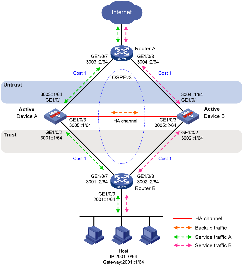
Procedure
1. Verify that Device A and Device B have software and hardware environment consistency.
2. Configure Router A:
|
|
NOTE: This step only provides the brief configuration procedure. |
# Assign 3003::2/64 to GigabitEthernet 1/0/7.
# Assign 3004::2/64 to GigabitEthernet 1/0/8.
# Configure OSPFv3 for Device A, Device B, and the routers to have Layer 3 reachability.
# Configure per-flow load sharing for IP forwarding.
3. Configure Router B:
|
|
NOTE: This step only provides the brief configuration procedure. |
# Assign 3001::2/64 to GigabitEthernet 1/0/7.
# Assign 3002::2/64 to GigabitEthernet 1/0/8.
# Configure OSPFv3 for Device A, Device B, and the routers to have Layer 3 reachability.
# Configure per-flow load sharing for IP forwarding.
4. Configure Device A:
a. Assign an IP address to GigabitEthernet 1/0/1.
<DeviceA> system-view
[DeviceA] interface gigabitethernet 1/0/1
[DeviceA-GigabitEthernet1/0/1] ipv6 address 3003::1/64
[DeviceA-GigabitEthernet1/0/1] ipv6 address auto link-local
[DeviceA-GigabitEthernet1/0/1] quit
# Assign IP addresses to other interfaces in the same way. (Details not shown.)
b. Add interfaces to security zones.
[DeviceA] security-zone name untrust
[DeviceA-security-zone-Untrust] import interface gigabitethernet 1/0/1
[DeviceA-security-zone-Untrust] quit
[DeviceA] security-zone name trust
[DeviceA-security-zone-Trust] import interface gigabitethernet 1/0/2
[DeviceA-security-zone-Trust] quit
c. Configure OSPFv3. Use the default OSPFv3 link cost configuration.
[DeviceA] ospfv3 1
[DeviceA-ospfv3-1] router-id 2.1.1.1
[DeviceA-ospfv3-1] quit
[DeviceA] interface gigabitethernet 1/0/1
[DeviceA-GigabitEthernet1/0/1] ospfv3 1 area 0
[DeviceA-GigabitEthernet1/0/1] quit
[DeviceA] interface GigabitEthernet1/0/2
[DeviceA-GigabitEthernet1/0/2] ospfv3 1 area 0
[DeviceA-GigabitEthernet1/0/2] quit
d. Configure a security policy.
Perform this task only on the primary device. After the HA group is set up, the secondary device automatically synchronizes its security policy configuration with the primary device.
# Configure security policy rule named trust-untrust to permit the packets from 2001::0/64 to the Internet.
[DeviceA] security-policy ipv6
[DeviceA-security-policy-ipv6] rule name trust-untrust
[DeviceA-security-policy-ipv6-3-trust-untrust] source-zone trust
[DeviceA-security-policy-ipv6-3-trust-untrust] destination-zone untrust
[DeviceA-security-policy-ipv6-3-trust-untrust] source-ip-subnet 2001::0 64
[DeviceA-security-policy-ipv6-3-trust-untrust] action pass
[DeviceA-security-policy-ipv6-3-trust-untrust] quit
# Configure rules to permit OSPFv3 protocol packets.
[DeviceA-security-policy-ipv6] rule name ospf1
[DeviceA-security-policy-ipv6-4-ospf1] source-zone trust
[DeviceA-security-policy-ipv6-4-ospf1] destination-zone local
[DeviceA-security-policy-ipv6-4-ospf1] service ospf
[DeviceA-security-policy-ipv6-4-ospf1] action pass
[DeviceA-security-policy-ipv6-4-ospf1] quit
[DeviceA-security-policy-ipv6] rule name ospf2
[DeviceA-security-policy-ipv6-5-ospf2] source-zone local
[DeviceA-security-policy-ipv6-5-ospf2] destination-zone trust
[DeviceA-security-policy-ipv6-5-ospf2] service ospf
[DeviceA-security-policy-ipv6-5-ospf2] action pass
[DeviceA-security-policy-ipv6-5-ospf2] quit
[DeviceA-security-policy-ipv6] rule name ospf3
[DeviceA-security-policy-ipv6-6-ospf3] source-zone untrust
[DeviceA-security-policy-ipv6-6-ospf3] destination-zone local
[DeviceA-security-policy-ipv6-6-ospf3] service ospf
[DeviceA-security-policy-ipv6-6-ospf3] action pass
[DeviceA-security-policy-ipv6-6-ospf3] quit
[DeviceA-security-policy-ipv6] rule name ospf4
[DeviceA-security-policy-ipv6-7-ospf4] source-zone local
[DeviceA-security-policy-ipv6-7-ospf4] destination-zone untrust
[DeviceA-security-policy-ipv6-7-ospf4] service ospf
[DeviceA-security-policy-ipv6-7-ospf4] action pass
[DeviceA-security-policy-ipv6-7-ospf4] quit
[DeviceA-security-policy-ipv6] quit
e. Configure HA group settings.
# Associate track entries with interfaces.
[DeviceA] track 1 interface gigabitethernet 1/0/1
[DeviceA-track-1] quit
[DeviceA] track 2 interface gigabitethernet 1/0/2
[DeviceA-track-2] quit
# Set up an HA group.
[DeviceA] remote-backup group
[DeviceA-remote-backup-group] remote-ipv6 3005::2
[DeviceA-remote-backup-group] local-ipv6 3005::1
[DeviceA-remote-backup-group] data-channel interface gigabitethernet 1/0/3
[DeviceA-remote-backup-group] device-role primary
RBM_P[DeviceA-remote-backup-group] backup-mode dual-active
RBM_P[DeviceA-remote-backup-group] hot-backup enable
RBM_P[DeviceA-remote-backup-group] configuration auto-sync enable
RBM_P[DeviceA-remote-backup-group] configuration sync-check interval 12
RBM_P[DeviceA-remote-backup-group] delay-time 1
# Configure the HA group to change the link costs advertised in OSPFv3 routes to 1.
RBM_P[DeviceA-remote-backup-group] adjust-cost ospfv3 enable absolute 1
# Configure the HA group to monitor the status of track entry 1 and track entry 2.
RBM_P[DeviceA-remote-backup-group] track 1
RBM_P[DeviceA-remote-backup-group] track 2
RBM_P[DeviceA-remote-backup-group] quit
f. Configure security services on Device A. (Details not shown.)
5. Configure Device B:
a. Assign IP addresses to interfaces.
<DeviceB> system-view
[DeviceB] interface gigabitethernet 1/0/1
[DeviceB-GigabitEthernet1/0/1] ipv6 address 3004::1/64
[DeviceB-GigabitEthernet1/0/1] ipv6 address auto link-local
[DeviceB-GigabitEthernet1/0/1] quit
# Assign IP addresses to other interfaces in the same way. (Details not shown.)
b. Add interfaces to security zones.
[DeviceB] security-zone name untrust
[DeviceB-security-zone-Untrust] import interface gigabitethernet 1/0/1
[DeviceB-security-zone-Untrust] quit
[DeviceB] security-zone name trust
[DeviceB-security-zone-Trust] import interface gigabitethernet 1/0/2
[DeviceB-security-zone-Trust] quit
c. Configure OSPFv3. Use the default OSPFv3 link cost configuration.
[DeviceB] ospfv3 1
[DeviceB-ospfv3-1] router-id 3.1.1.1
[DeviceB-ospfv3-1] quit
[DeviceB] interface gigabitethernet 1/0/1
[DeviceB-GigabitEthernet1/0/1] ospfv3 1 area 0
[DeviceB-GigabitEthernet1/0/1] quit
[DeviceB] interface GigabitEthernet1/0/2
[DeviceB-GigabitEthernet1/0/2] ospfv3 1 area 0
[DeviceB-GigabitEthernet1/0/2] quit
d. Configure HA group settings.
# Associate track entries with interfaces.
[DeviceB] track 1 interface gigabitethernet 1/0/1
[DeviceB-track-1] quit
[DeviceB] track 2 interface gigabitethernet 1/0/2
[DeviceB-track-2] quit
# Set up an HA group.
[DeviceB] remote-backup group
[DeviceB-remote-backup-group] remote-ipv6 3005::1
[DeviceB-remote-backup-group] local-ipv6 3005::2
[DeviceB-remote-backup-group] data-channel interface gigabitethernet 1/0/3
[DeviceB-remote-backup-group] device-role secondary
RBM_S[DeviceB-remote-backup-group] backup-mode dual-active
RBM_S[DeviceB-remote-backup-group] hot-backup enable
RBM_S[DeviceB-remote-backup-group] configuration auto-sync enable
RBM_S[DeviceB-remote-backup-group] configuration sync-check interval 12
RBM_S[DeviceB-remote-backup-group] delay-time 1
# Configure the HA group to change the link costs advertised in OSPFv3 routes to 1.
RBM_S[DeviceB-remote-backup-group] adjust-cost ospfv3 enable absolute 1
# Configure the HA group to monitor the status of track entry 1 and track entry 2.
RBM_S[DeviceB-remote-backup-group] track 1
RBM_S[DeviceB-remote-backup-group] track 2
RBM_S[DeviceB-remote-backup-group] quit
6. On the hosts, specify 2002::1 as the default gateway. (Details not shown.)
Verifying the configuration
1. Verify the configuration on Device A:
# Verify that the HA channels have been set up.
RBM_P[DeviceA] display remote-backup-group status
Remote backup group information:
Backup mode: Dual-active
Device management role: Primary
Device running status: Active
Data channel interface: GigabitEthernet1/0/3
Local IPv6: 3005::1
Remote IPv6: 3005::2 Destination port: 60064
Control channel status: Connected
Keepalive interval: 1s
Keepalive count: 10
Configuration consistency check interval: 12 hour
Configuration consistency check result: Not Performed
Configuration backup status: Auto sync enabled
Session backup status: Hot backup enabled
Delay-time: 1 min
Uptime since last switchover: 0 days, 3 hours, 11 minutes
Switchover records:
Time Status change Cause
2021-06-22 13:33:33 Initial to Active Interface status changed
# Verify that the OSPFv3 routes advertised by Device A and Device B include the same link cost.
RBM_P[DeviceA] display ospfv3 interface
OSPFv3 Process 1 with Router ID 2.1.1.1
Area: 0.0.0.0
-------------------------------------------------------------------------
ID State Cost Pri DR BDR Ins Name
2 DR 1 1 2.1.1.1 1.1.1.1 0 GE1/0/1
3 BDR 1 1 4.1.1.1 2.1.1.1 0 GE1/0/2
2. Verify the configuration on Device B:
# Verify that the HA channels have been set up.
RBM_S[DeviceB] display remote-backup-group status
Remote backup group information:
Backup mode: Dual-active
Device management role: Secondary
Device running status: Active
Data channel interface: GigabitEthernet1/0/3
Local IPv6: 3005::2
Remote IPv6: 3005::1 Destination port: 60064
Control channel status: Connected
Keepalive interval: 1s
Keepalive count: 10
Configuration consistency check interval: 12 hour
Configuration consistency check result: Not Performed
Configuration backup status: Auto sync enabled
Session backup status: Hot backup enabled
Delay-time: 1 min
Uptime since last switchover: 0 days, 3 hours, 11 minutes
Switchover records:
Time Status change Cause
2021-06-22 13:33:33 Initial to Active Interface status changed
# Verify that the OSPFv3 routes advertised by Device A and Device B include the same link cost.
RBM_S[DeviceB] display ospfv3 interface
OSPFv3 Process 1 with Router ID 3.1.1.1
Area: 0.0.0.0
-------------------------------------------------------------------------
ID State Cost Pri DR BDR Ins Name
2 DR 1 1 3.1.1.1 1.1.1.1 0 GE1/0/1
3 BDR 1 1 4.1.1.1 3.1.1.1 0 GE1/0/2
