- Table of Contents
- Related Documents
-
| Title | Size | Download |
|---|---|---|
| 01-Text | 11.29 MB |
Determining the installation position
Connecting the grounding cable
Connecting the AP to the network
Verifying network connectivity when the AP operates in fit mode
Verifying network connectivity when the AP operates in fat mode
Connecting the AP to a configuration terminal from the console port
Setting parameters for the configuration terminal
Logging in to the AP from the console port
Login from the Web interface or through Telnet
4 Appendix A Technical specifications
6 Appendix C Transceiver modules
1 Preparing for installation
Safety recommendations
|
|
WARNING! Only professional technical engineers are allowed to install and remove the AP and its accessories. Read the safety instructions carefully before installing or servicing the AP. |
To avoid possible bodily injury and equipment damage, read the following safety recommendations before installing the AP. Note that the recommendations do not cover every possible hazardous condition.
· To avoid bodily injury and device damage, take adequate safety measures.
· Place the AP in a dry, flat location and take anti-slip measures.
· Keep the AP clean and dust-free.
· Do not place the AP in a moist area and avoid liquid splashes.
· Keep the AP and installation tools away from walkways.
· Before installation, locate the emergency power switch in the equipment room so that you can cut off power immediately in case of an emergency.
· Before you install, remove, move, or service the AP, turn off power to the AP and remove the power cord and cables from the AP.
· When performing electrical operations, you must comply with local laws and regulations. The relevant staff must have corresponding qualifications.
· To avoid electric shocks, use a yellow-green grounding cable to ground the AP.
· Before connecting or disconnecting the power cord, you must disconnect power from the AP.
· Use a waterproof enclosure to protect the AP from water and other adverse environmental elements.
Site preparation
Before installing the AP, examine the installation site and make sure the AP will operate in a favorable environment. Make sure the temperate and humidity at the installation site meets the requirements in Table1-1.
Table1-1 Temperature and humidity requirements
|
Item |
Specification |
|
Operating temperature |
–40°C to +70°C (–40°F to +158°F) |
|
Storage temperature |
–40°C to +85°C (–40°F to +185°F) |
|
Operating humidity (RH), noncondensing |
5% to 95% |
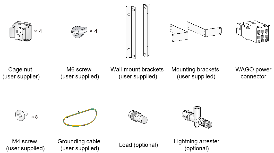
Installation accessories
Figure1-1 Installation accessories
Installation tools
When installing the AP, you might need the following tools. Prepare the installation tools yourself as required.
Figure1-2 Installation tools

2 Installing the AP
Installation flowchart
Figure2-1 Installation flowchart

Pre-installation tasks
Before installing the AP, perform the following tasks:
· Connect the AP to a power source and the network. Examine the LEDs to verify that the AP can operate correctly. For information about AP LEDs, see "Appendix B Ports and LEDs."
· Record the MAC address and serial number of the AP for future use.
Determining the installation position
When selecting an installation position for the AP, follow these guidelines:
· Keep the AP away from electronic equipment or devices (such as microwave ovens) that might generate radio frequency noise.
· Make sure the AP does not hinder people’s daily work and life.
· Do not install the AP under water seeping, dripping, soaking, or condensing environment and prevent water droplets from flowing into the AP along cables.
· Install the AP in a location accessible only to professional technical engineers, and the installation and maintenance of AP must be performed by professional technical engineers.
· Ensure that the AP is installed in a weak electric box or device with a protection level of IP54 or higher.
Mounting the AP
The AP can be installed only indoors. You can mount the AP on a wall or in a rack.
Installation brackets
Wall-mount brackets are required for wall-mounting the AP. Mounting brackets are required for rack-mounting the AP.
No wall-mount brackets or mounting brackets are provided with the AP. Purchase or order the brackets yourself as required. See Figure2-2 for the required dimensions of the wall-mount brackets and mounting brackets.

Figure2-3 Mounting brackets

Mounting the AP on a wall
1. Use M4 screws to attach the wall-mount brackets to the AP and fasten the screws.
Figure2-4 Attaching the wall-mount brackets to the AP

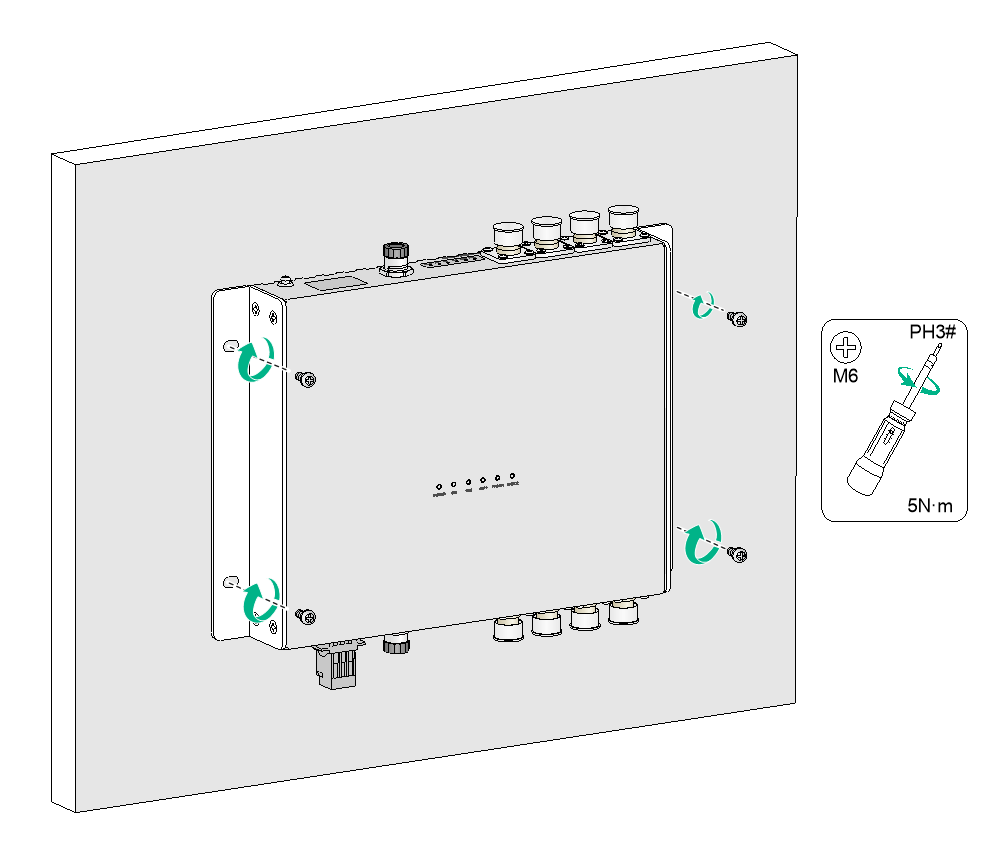
2. Use M6 screws to attach the AP to a power distribution cabinet.
Figure2-5 Attaching the AP to a power distribution cabinet
Mounting the AP in a rack
1. Wear an ESD wrist strap. Make sure the wrist strap makes good skin contact and is reliably grounded.
2. Make sure the rack is stable and reliably grounded.
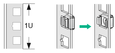
3. Use the mounting brackets to mark the cage nut installation positions on the rack posts and then install cage nuts.
Figure2-6 Installing cage nuts
4. Use the M4 mounting bracket screws to attach the mounting brackets to the AP.
Figure2-7 Attaching mounting brackets to the AP

5. Supporting the bottom of the AP with one hand and holding the front of the AP with the other, gently push the AP into the rack. Then use M6 rack screws and cage nuts to attach the mounting brackets to the rack posts. Make sure the AP is attached securely to the rack.
Figure2-8 Mounting the AP in a rack

Connecting the grounding cable
|
|
CAUTION: · Correctly connecting the grounding cable is crucial to lightning protection and EMI protection. Before installing or using the AP, connect a grounding cable to the AP correctly. · Connect the grounding cable to the engineering ground in the equipment room. Do not connect it to a fire main or lightning rod. · Lightning arresters are not required for antenna ports if the AP is grounded reliably. |
To connect the grounding cable to the AP:
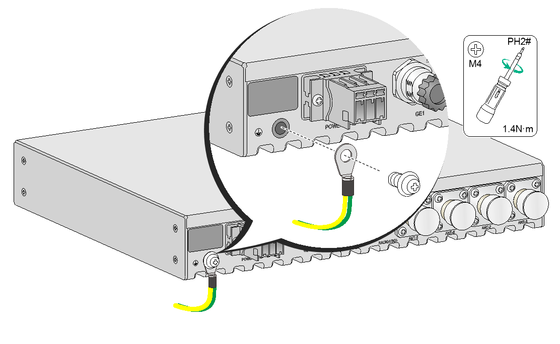
1. Use a Phillips screwdriver to remove the grounding screw from the grounding hole in the rear panel of the AP.
2. Attach the grounding screw to the ring terminal of the grounding cable.
3. Use a Phillips screwdriver to fasten the grounding screw into the grounding hole.
4. Connect the other end of the grounding cable to the grounding cable in the train compartment or the power distribution cabinet.
Figure2-9 Connecting the grounding cable
Connecting RF cables
|
|
CAUTION: · In areas where thunderstorms frequently occur, purchase and install lightning arresters for the antenna ports. · Install lightning arresters for the antenna ports in sequence from left to right or from right to left. · Lightning arresters are not required for the antenna ports if the AP is grounded reliably. |
|
|
IMPORTANT: Radio 1 operates in the 5 GHz band. Radio 2 can operate in either 2.4 GHz or 5 GHz band. |
|
|
CAUTION: To avoid device damage or bodily injury caused by excessive radiation exposure, make sure the antennas and RF cables comply with local regulations. As a best practice, purchase H3C recommended antennas and RF cables. To enure correct operatison of the AP, make sure the antennas and RF cables meet the following basic requirements: · The VSWR for RF cables is less than or equal to 1.4. · The VSWR for antennas is less than or equal to 1.8. · The maximum gain can ensure that the AP's EIRP complies with local regulations. |
An RF cable is used to connect an antenna port to an external antenna.
To connect an RF cable:
1. Remove the weatherproof cap from the antenna port on the AP.
2. Connect a lightning arrester to the antenna port.
3. Connect the RF cable to the lightning arrester.
Figure2-10 Connecting an RF cable
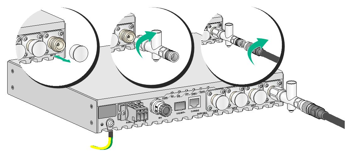
4. Install a load for each unused antenna port.
Figure2-11 Installing a load for an antenna port

Connecting an optical fiber
To connect the fiber port on the AP to the network, first install a transceiver module in the fiber port and then connect an optical fiber to the transceiver module. The fiber port on the AP supports only optical fibers with an LC connector. No transceiver modules are provided with the AP. Purchase one as required. For more information about transceiver modules available for the AP, see "Appendix C Transceiver modules."
To connect an optical fiber:
1. Remove the dust plug from the fiber port.
2. Pull the bail latch on the transceiver module upwards to catch the knob on the top of the transceiver module. Take the transceiver module by its two sides and push the end without the bail latch gently into the port until it snaps into place.
3. Identify the Rx and Tx ports on the transceiver module. Use the optical fiber with LC connectors to connect the Rx port and Tx port on the AP to the Tx port and Rx port on the peer device, respectively.
4. Observe the port LED to verify link connectivity.
¡ If the LED is on, the link is connected.
¡ If the LED is off, the link is not connected. Identify the issue and resolve it.
Figure2-12 Connecting an optical fiber

Connecting an M12 cable
Remove the dust plug from the M12 connector on the AP. Align the projection on the M12 cable connector with the groove on the AP-side connector and insert the cable connector into the AP. Then fasten the connector to secure it into place.
Figure2-13 Connecting an M12 cable

No M12 cable is provided with the AP, you can purchase or make an M12 cable yourself as required. Table2-1 describes the M12 connector pinouts against the RJ-45 connector.
Table2-1 M12 connector pinouts against the RJ-45 connector

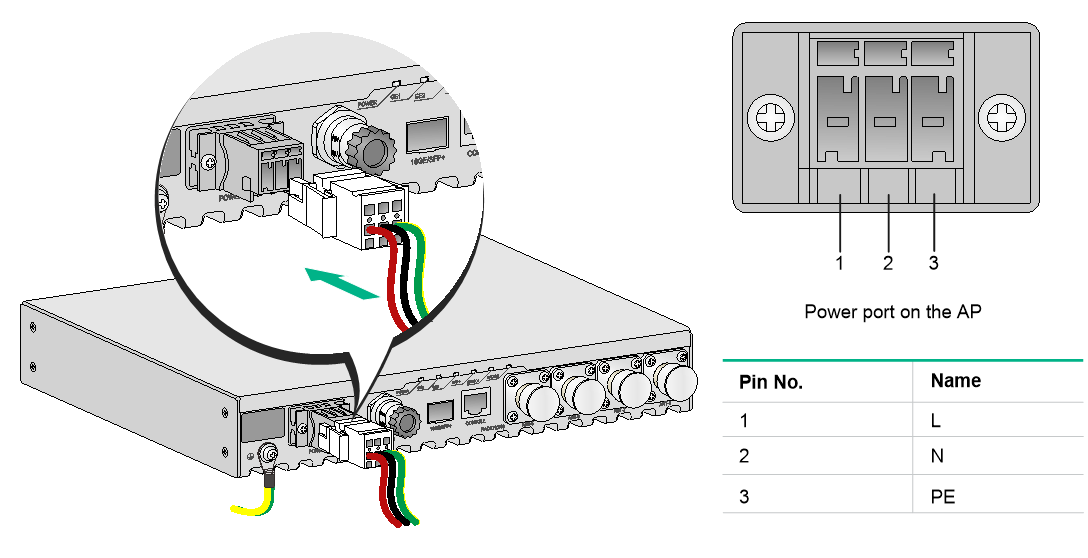
Connecting the power cord
|
|
WARNING! · When connecting the power cord, first connect it to the AP, and then connect it to the power source. · Verify that the local power source is reliably grounded each time before powering on the AP. |
The AP supports AC or DC power input. See Table2-2 for the power input specifications.
Table2-2 Power input specifications
|
Item |
Specification |
|
DC power input |
70 V to 130 V |
|
AC power input |
100 V to 240 V @ 50/60 Hz |
Connecting the power cord to a Wago connector
1. Strip 10 mm (0.39 in) of insulation off one end of the power cord.
2. Use a flathead screwdriver to press down the movable tab in the target hole.
3. Insert the power cord into the wire inlet.
4. Take away the flathead screwdriver.
Figure2-14 Connecting the power cord to a Wago connector

Connecting a DC power cord
1. Make sure the AP is reliably grounded.
2. Connect one end of the DC power cord to the power port on the AP and the other end to a local power source.
Figure2-15 Connecting a DC power cord

Connecting an AC power cord
1. Make sure the AP is reliably grounded.
2. Connect one end of the AC power cord to the power port on the AP and the other end to a local power source.
Figure2-16 Connecting an AC power cord
Verifying the power cord connection
Observe the LEDs on the AP to verify the power cord connection. For more information about the LEDs, see "Appendix B Ports and LEDs."
Connecting the AP to the network
For the AP to access the Internet or MAN, connect an Ethernet port on the AP to an Ethernet switch.
Verifying network connectivity when the AP operates in fit mode
When the AP operates in fit mode, all its settings are configured on the AC. Execute the display wlan ap all command on the AC. If the AP status in the command output is R/M, the AP has associated with the AC and connected to the network.
Total number of APs: 1
Total number of connected APs: 1
Total number of connected manual APs: 1
Total number of connected auto APs: 0
Total number of connected common APs: 1
Total number of connected WTUs: 0
Total number of inside APs: 0
Maximum supported APs: 3072
Remaining APs: 3071
Total AP licenses: 128
Remaining AP licenses: 127
AP information
State : I = Idle, J = Join, JA = JoinAck, IL = ImageLoad
C = Config, DC = DataCheck, R = Run M = Master, B = Backup
AP name AP ID State Model Serial ID
ap1 1 R/M WA6628E-T 219801A2ES8209E00014
Verifying network connectivity when the AP operates in fat mode
When the AP operates in fat mode, use the ping command on it to ping the uplink network device. If the ping operation succeeds, the AP is connected to the network successfully.
3 Accessing the AP
|
|
IMPORTANT: The AP is typically installed on a high position. As a best practice, log in to and configure the AP before installing it. |
This section applies only when the AP operates in fat mode. When the AP operates in fat mode, you can log in to the AP from the console port, Web interface, or through Telnet.
Before logging in to the device, you must obtain the AP's IP address. To access the AP for the first time, you must log in to the AP from the console port. Then you can configure other login methods.
Login from the console port
Prepare the following items for accessing the device through the console port:
· An 8-core console cable, with a crimped RJ-45 connector at one end, and a DB-9 connector at the other end.
· A configuration terminal. It can be a standard character terminal with an RS-232 port, or a PC.
Connecting the AP to a configuration terminal from the console port
|
|
CAUTION: · The serial ports on PCs do not support hot swapping. To connect a PC to an operating device, first connect the PC end. To disconnect a PC from an operating device, first disconnect the device end. · If the PC does not have an RS-232 port but a USB port, use a USB-to-RS-232 converter to connect the USB port to the console cable and install the corresponding driver on the PC. |
To connect the AP to a configuration terminal from the console port:
1. Connect the DB-9 connector of the console cable to the serial port on the configuration terminal, for example, a PC.
2. Connect the RJ-45 connector of the console cable to the console port on the AP.
Figure3-1 Connecting the AP to a PC from the console port

Setting parameters for the configuration terminal
To configure and manage the AP from the console port, you must run a terminal emulator program, such as TeraTermPro, on your configuration terminal. You can use the emulator program to connect a network device, a Telnet site, or an SSH site. For more information about the terminal emulator programs, see the user guides for these programs.
Configure the terminal parameters as follows:
· Bits per second—9,600.
· Data bits—8.
· Parity—None.
· Stop bits—1.
· Flow control—None.
Logging in to the AP from the console port
Verify that the AP is connected correctly to the configuration terminal and the configuration terminal parameters are configured correctly. Then power on the AP. You can see the following information on the configuration terminal:
System is starting...
Booting Normal Extend BootWare.
……
System application is starting...
Startup configuration file does not exist.
User interface con0 is available.
Press ENTER to get started.
Login from the Web interface or through Telnet
By default, you can log in to the device from the Web interface or through Telnet. The following default login information is defined for your login:
· Username—admin.
· Password—h3capadmin.
· Management IP address of VLAN-interface 1—192.168.0.50 with subnet mask 255.255.255.0. If the default IP address has been changed, contact the administrator to get the new IP address.
4 Appendix A Technical specifications
Table4-1 Technical specifications
|
Item |
Specification |
|
Dimensions (H × W × D) |
40 × 260 × 210 mm (1.57 × 10.24 × 8.27 in) |
|
Weight |
2.4 kg (5.29 lb) |
|
Antenna |
External antenna |
|
Power consumption |
8 W to 40 W |
|
Radios |
2 |
|
Protocols and standards |
IEEE802.11a/b/g/n/ac/ax |
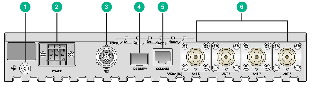
5 Appendix B Ports and LEDs
Ports
The AP provides the following ports:
· One power port
· One 10 GE Ethernet fiber port
· Two 10/100/1000M Ethernet ports with an M12 connector
· One console port
· Four 5G antenna ports
· Four 2.4G/5G antenna ports
Figure5-1 Ports on the front panel of the AP
|
(1) Grounding screw |
(2) Power port |
|
(3) 10/100/1000M Ethernet port with an M12 connector |
|
|
(4) 10 GE Ethernet fiber port |
(5) Console port |
|
(6) 5G antenna port |
|
Figure5-2 Ports on the rear panel of the AP

|
(1) 2.4G/5G antenna port |
(2) 10/100/1000M Ethernet port with an M12 connector |
|
(3) Grounding screw |
|
Table5-1 Port descriptions
|
Port |
Standards and protocols |
Description |
|
Console port |
RS/EIA-232 |
Used only for device configuration and management by technical support. |
|
GE1/GE2 |
· IEEE802.3 · IEEE802.3u |
Used for connecting the AP to an uplink device for Internet or MAN access. It is represented by interface number GE1/0/1 and GE1/0/2 in the MAP file and GigabitEthernet 1 and GigabitEthernet 2 for configuration on the AC. |
|
10GE/SFP+ |
· IEEE802.3 · IEEE802.3u |
Used for connecting the AP to an uplink device for Internet or MAN access. It is represented by interface number XGE1/0/1 in the MAP file and Ten-GigabitEthernet 1 for configuration on the AC. |
|
5G antenna port |
· IEEE802.11a · IEEE802.11an · IEEE802.11ac · IEEE802.11ax |
Used for connecting to a 5G antenna. |
|
2.4G/5G antenna port |
· IEEE802.11b · IEEE802.11g · IEEE802.11gn · IEEE802.11gac · IEEE802.11a · IEEE802.11an · IEEE802.11ac · IEEE802.11ax |
Used for connecting to a 2.4G/5G antenna. |
|
Power port |
N/A |
Used for receiving power from the local power source. |
LEDs
Figure5-3 Front view of the AP

Figure5-4 Rear view of the AP
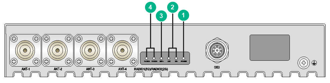
Figure5-5 Top view of the AP
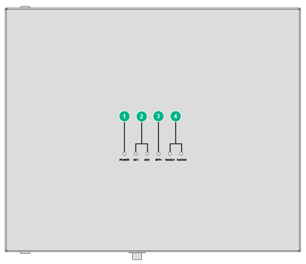
|
(1) Power LED |
(2) Ethernet port LEDs |
|
(3) 10GE/SFP+ port LED |
(4) Radio LEDs |
Table5-2 LED descriptions
|
LED |
Status |
Description |
|
|
POWER |
Yellow |
Steady on |
The AP is initializing, or an initialization exception has occurred. |
|
Flashing at 2 Hz |
The Ethernet interfaces are down and no mesh links are established. |
||
|
Green |
Steady on |
The AP has registered to an AC, but does not have any associated clients. |
|
|
Flashing at 0.5 Hz |
The AP has started up but has not registered to any AC. |
||
|
Flashing at 2 Hz |
The AP is upgrading the image. |
||
|
Off |
The AP has not been powered on or the LEDs on the AP have been turned off. |
||
|
RADIO1 |
Green |
Flashing at 1 Hz |
The radio has associated clients. |
|
Off |
The radio is disabled or the LED has been turned off. |
||
|
RADIO2 |
Green |
Flashing at 1 Hz |
The radio has associated clients. |
|
Off |
The radio is disabled or the LED has been turned off. |
||
|
GE1/GE2 |
Yellow |
Steady on |
The port rate is negotiated to 100/10 Mbps. |
|
Flashing |
The port is operating at 100/10 Mbps. |
||
|
Green |
Steady on |
The port rate is negotiated to 1000 Mbps. |
|
|
Flashing |
The port is operating at 1000 Mbps. |
||
|
Off |
No Ethernet ports are connected. |
||
|
10GE/SFP+ |
Yellow |
Steady on |
The port rate is negotiated to 1000 Mbps. |
|
Flashing |
The port is operating at 1000 Mbps. |
||
|
Green |
Steady on |
The port rate is negotiated to 10 Gbps. |
|
|
Flashing |
The port is operating at 10 Gbps. |
||
|
Off |
No 10 GE or SFP+ ports are connected. |
||
6 Appendix C Transceiver modules
Views
You must use an SFP transceiver module and optical fiber with an LC connector to connect the fiber port on the AP.
Figure6-1 SFP transceiver module
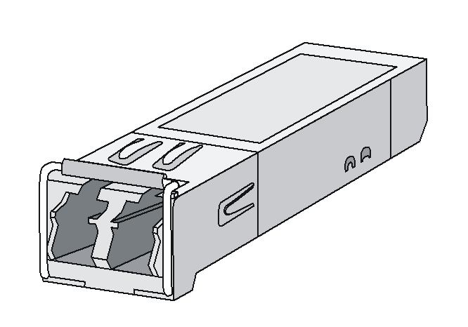
Figure6-2 Optical fibers with LC connectors
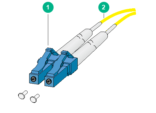
|
(1) LC connector |
(2) Optical fiber |
Specifications
Table6-1 SFP-XG-CPRI-IR-SM1310 transceiver module specifications
|
Item |
SFP-XG-CPRI-IR-SM1310 |
|
Central wavelength |
1310 nm |
|
Max transmission distance |
1.4 km (0.87 miles) |
|
Data rate |
4920 to 10310 Mb/s |
|
Connector type |
LC connector |
|
Fiber mode |
SMF |
|
Fiber diameter |
9/125 μm |
|
Output power |
–8.2 to +0.5 dBm |
Table6-2 SFP-XG-CPRI-LR-SM1310 specifications
|
Item |
SFP-XG-CPRI-LR-SM1310 |
|
Central wavelength |
1310 nm |
|
Max transmission distance |
10 km (6.21 miles) |
|
Data rate |
4920 to 10310 Mb/s |
|
Connector type |
LC connector |
|
Fiber mode |
SMF |
|
Fiber diameter |
9/125 μm |
|
Output power |
–8.2 to +0.5 dBm |
