- Table of Contents
-
- 20-Network Management and Monitoring Configuration Guide
- 00-Preface
- 01-System maintenance and debugging configuration
- 02-NQA configuration
- 03-SNMP configuration
- 04-RMON configuration
- 05-NETCONF configuration
- 06-EAA configuration
- 07-Process monitoring and maintenance configuration
- 08-Flow log configuration
- 09-Packet capture configuration
- 10-Mirroring configuration
- 11-Fast log output configuration
- 12-UCC configuration
- 13-SQA configuration
- Related Documents
-
| Title | Size | Download |
|---|---|---|
| 08-Flow log configuration | 140.45 KB |
Contents
Specifying a flow log export destination
Restrictions and guidelines for flow log export destination configuration
Specifying a log host as the flow log export destination
Specifying the information center as the flow log export destination
Configuring the flow log version
Specifying a source IP address for flow log packets
Configuring the timestamp of flow log entries
Enabling load balancing for flow log entries
Configuring flow log host groups
Prerequisites for log host group configuration
Configuring an IPv4 flow log host group
Configuring an IPv6 flow log host group
Display and maintenance commands for flow log
Flow log configuration examples
Example: Configuring flow log export
Example: Configuring flow log export to a flow log host group
Configuring flow log
About flow log
Flow log records users' access to external networks based on flows. Each flow is identified by a 5-tuple of the source IP address, destination IP address, source port, destination port, and protocol number.
Flow log creates entries based on NAT sessions.
Flow log export
You can export flow log entries in the following methods:
· Export flow log entries to log hosts. Flow log entries are sent as binary characters in UDP. One UDP packet can contain multiple log entries.
· Export flow log entries to the information center. Flow log entries are converted to syslog entries in ASCII format, with the informational severity level. The information center specifies the output destinations for the logs. Available output destinations include the console, log host, and log file. For more information about the information center, see System Management Configuration Guide.
Log entries in ASCII format are human readable. However, the log data volume is higher in ASCII format than in binary format.
Flow log versions
Flow log has three versions: version 1.0, version 3.0, and version 5.0. Table 1, Table 2, and Table 3 show the fields available in the versions.
|
Field |
Description |
|
SrcIP |
Source IP address before NAT. |
|
DestIP |
Destination IP address before NAT. |
|
SrcPort |
Source TCP/UDP port number before NAT. |
|
DestPort |
Destination TCP/UDP port number before NAT. |
|
StartTime |
Start time of the flow, in seconds. |
|
EndTime |
End time of the flow, in seconds. This field is 0 if the Operator field is 6 (regular connectivity check record for the active flow). |
|
Protocol |
Protocol number. |
|
Operator |
Reasons why a flow log entry was generated: · 0—Reserved. · 1—Flow was ended normally. · 2—Flow was aged out because of aging timer expiration. · 3—Flow was aged out because of configuration change or manual deletion. · 4—Flow was aged out because of insufficient resources. · 5—Reserved. · 6—Regular connectivity check record for the active flow. · 7—Flow was deleted because a new flow was created when the flow table was full. · 8—Flow was created. · FE—Other reasons. · 10-FE-1—Reserved for future use. |
|
Reserved |
Reserved for future use. |
Table 2 Flow log 3.0 fields
|
Field |
Description |
|
Protocol |
Protocol number. |
|
Operator |
Reasons why a flow log was generated: · 0—Reserved. · 1—Flow was ended normally. · 2—Flow was aged out because of aging timer expiration. · 3—Flow was aged out because of configuration change. · 4—Flow was aged out because of insufficient resources. · 5—Reserved. · 6—Regular connectivity check record for the active flow. · 7—Flow was deleted because a new flow was created when the flow table was full. · 8—Flow was created. · FE—Other reasons. · 10-FE-1—Reserved for future use. |
|
IPVersion |
IP packet version. |
|
TosIPv4 |
ToS field of the IPv4 packet. |
|
SourceIP |
Source IP address before NAT. |
|
SrcNatIP |
Source IP address after NAT. |
|
DestIP |
Destination IP address before NAT. |
|
DestNatIP |
Destination IP address after NAT. |
|
SrcPort |
Source TCP/UDP port number before NAT. |
|
SrcNatPort |
Source TCP/UDP port number after NAT. |
|
DestPort |
Destination TCP/UDP port number before NAT. |
|
DestNatPort |
Destination TCP/UDP port number after NAT. |
|
StartTime |
Start time of the flow, in seconds. |
|
EndTime |
End time of the flow, in seconds. This field is 0 when the Operator field is 6 (regular connectivity check record for the active flow). |
|
InTotalPkg |
Number of packets received for the session. |
|
InTotalByte |
Number of bytes received for the session. |
|
OutTotalPkg |
Number of packets sent for the session. |
|
OutTotalByte |
Number of bytes sent for the session. |
|
InVPNID |
ID of the source VPN instance. |
|
OutVPNID |
ID of the destination VPN instance. |
|
Reserved1 |
Reserved field. |
|
AppID |
Application protocol ID. |
|
Reserved3 |
Reserved field. |
|
Field |
Description |
|
Protocol |
Protocol number. |
|
Operator |
Reasons why a flow log was generated: · 0—Reserved. · 1—Flow was ended normally. · 2—Flow was aged out because of aging timer expiration. · 3—Flow was aged out because of configuration change. · 4—Flow was aged out because of insufficient resources. · 5—Reserved. · 6—Regular connectivity check record for the active flow. · 7—Flow was deleted because a new flow was created when the flow table was full. · 8—Flow was created. · FE—Other reasons. · 10-FE-1—Reserved for future use. |
|
IPVersion |
IP packet version. |
|
TosIPv4 |
ToS field of the IPv4 packet. |
|
SourceIP |
Source IP address before NAT. |
|
SrcNatIP |
Source IP address after NAT. |
|
DestIP |
Destination IP address before NAT. |
|
DestNatIP |
Destination IP address after NAT. |
|
SrcPort |
Source TCP/UDP port number before NAT. |
|
SrcNatPort |
Source TCP/UDP port number after NAT. |
|
DestPort |
Destination TCP/UDP port number before NAT. |
|
DestNatPort |
Destination TCP/UDP port number after NAT. |
|
StartTime |
Start time of the flow, in seconds. |
|
EndTime |
End time of the flow, in seconds. This field is 0 when the Operator field is 6 (regular connectivity check record for the active flow). |
|
InTotalPkg |
Number of packets received for the session. |
|
InTotalByte |
Number of bytes received for the session. |
|
OutTotalPkg |
Number of packets sent for the session. |
|
OutTotalByte |
Number of bytes sent for the session. |
|
InVPNID |
ID of the source VPN instance. |
|
OutVPNID |
ID of the destination VPN instance. |
|
AppID |
Application protocol ID. |
|
UserName |
Username. |
|
Reserved1 Reserved2 Reserved3 |
Reserved fields. |
Flow log tasks at a glance
To configure flow log, perform the following tasks:
1. Specifying a flow log export destination
Choose one of the following tasks:
¡ Specifying a log host as the flow log export destination
¡ Specifying the information center as the flow log export destination
2. (Optional.) Configuring the flow log version
3. (Optional.) Specifying a source IP address for flow log packets
4. (Optional.) Configuring the timestamp of flow log entries
5. (Optional.) Enabling load balancing for flow log entries
6. (Optional.) Configuring flow log host groups
Prerequisites for flow log
Before you configure the flow log feature, complete the following tasks:
· Enable NAT logging by using the nat log enable command.
· Enable the following NAT logging features as needed:
¡ Logging of active NAT flows.
¡ Logging of NAT session establishment events.
¡ Logging of NAT session removal events.
For more information about the NAT logging commands, see Network Connectivity Command Reference.
Specifying a flow log export destination
Restrictions and guidelines for flow log export destination configuration
You can export flow log entries to a log host or the information center, but not both. If you configure both methods, the system exports flow log entries to the information center.
Flow log entries exported to the information center has the informational severity level.
Specifying a log host as the flow log export destination
1. Enter system view.
system-view
2. Specify a log host as the destination for flow log export.
userlog flow export host { hostname | ipv4-address | ipv6 ipv6-address } port udp-port
By default, no log hosts are specified.
You can specify multiple log hosts.
Specifying the information center as the flow log export destination
1. Enter system view.
system-view
2. Specify the information center as the destination for flow log export.
userlog flow syslog
By default, flow log entries are not exported to the information center.
Configuring the flow log version
Restrictions and guidelines
Make sure the specified flow log version is supported on the log host.
If you configure the flow log version multiple times, the most recent configuration takes effect.
Procedure
1. Enter system view.
system-view
2. Configure the flow log version.
userlog flow export version version-number
The default flow log version is 1.0.
Specifying a source IP address for flow log packets
About this task
By default, the source IP address for flow log packets is the IP address of their outgoing interface. For the log hosts to filter log entries by log sender, specify a source IP address for all flow log packets.
Restrictions and guidelines
As a best practice, use a Loopback interface's address as the source IP address for flow log packets. A Loopback interface is always up. The setting avoids export failure on interfaces that might go down.
Procedure
1. Enter system view.
system-view
2. Specify a source IP address for flow log packets.
userlog flow export source-ip { ipv4-address | ipv6 ipv6-address }
By default, the source IP address for flow log packets is the IP address of their outgoing interface.
Configuring the timestamp of flow log entries
About this task
The device uses either the local time or the UTC time in the timestamp of flow logs.
· UTC time—Standard Greenwich Mean Time (GMT).
· Local time—Standard GMT plus or minus the time zone offset.
The time zone offset can be configured by using the clock timezone command. For more information, see device management in System Management Command Reference.
Procedure
1. Enter system view.
system-view
2. Configure the device to use the local time in the flow log timestamp.
userlog flow export timestamp localtime
By default, the UTC time is used in the flow log timestamp.
Enabling load balancing for flow log entries
About this task
By default, the device sends a copy of each flow log entry to all configured log hosts. When one log host fails, other log hosts still have complete flow log entries.
In load balancing mode, flow log entries are distributed among log hosts based on the source IP addresses (before NAT) that are recorded in the entries. The flow log entries generated for the same source IP address are sent to the same log host.
Restrictions and guidelines
In load balancing mode, flow logs are load balanced among all configured log hosts, regardless of whether the log hosts are reachable. If a log host is unreachable, the flow logs sent to it will be lost.
Procedure
1. Enter system view.
system-view
2. Enable load balancing for flow log entries.
userlog flow export load-balancing
By default, load balancing is disabled.
Configuring flow log host groups
About flow log host group
By default, the device sends a copy of each flow log entry to all available log hosts. To filter logs and reduce the log sending and processing workload of the device, configure the flow log host group feature.
The flow log host group feature allows you to classify flow log hosts into groups and specify an ACL for each group. A flow log matches a log host group if it matches the group's ACL, and it is sent only to the log hosts in the matching group.
If a flow log matches multiple log host groups, the device sends the log to the group that comes first in alphabetical order of the matching group names.
If a flow log does not match any log host groups, the device ignores the log host group configuration and sends the log to all configured log hosts.
If load balancing is enabled, flow logs sent to a log host group will be load-shared among the log hosts in the group. Flow logs generated for the same source IP address are sent to the same log host.
Prerequisites for log host group configuration
Before you configure flow log host groups, complete the following tasks:
· Configure the ACLs to be used by the flow log host groups.
· Use the userlog flow export host command to configure the log hosts to be assigned to the flow log host groups.
Configuring an IPv4 flow log host group
1. Enter system view.
system-view
2. Create an IPv4 flow log host group and enter its view.
userlog host-group host-group-name acl { name acl-name | number acl-number }
By default, no IPv4 flow log host groups exist.
3. Assign an IPv4 log host to the flow log host group.
userlog host-group host flow { hostname | ipv4-address }
By default, an IPv4 flow log host group does not contain any log hosts.
Configuring an IPv6 flow log host group
1. Enter system view.
system-view
2. Create an IPv6 flow log host group and enter its view.
userlog host-group ipv6 host-group-name acl { name acl-name | number acl-number }
By default, no IPv6 flow log host groups exist.
3. Assign an IPv6 log host to the flow log host group.
userlog host-group host flow ipv6 { hostname | ipv6-address }
By default, an IPv6 flow log host group does not contain any log hosts.
Display and maintenance commands for flow log
Execute display commands in any view.
|
Task |
Command |
|
Display flow log configuration and statistics. |
display userlog export |
|
Display flow log host group information. |
display userlog host-group [ ipv6 ] [ host-group-name ] |
|
Clear flow log statistics. |
reset userlog flow export |
Flow log configuration examples
Example: Configuring flow log export
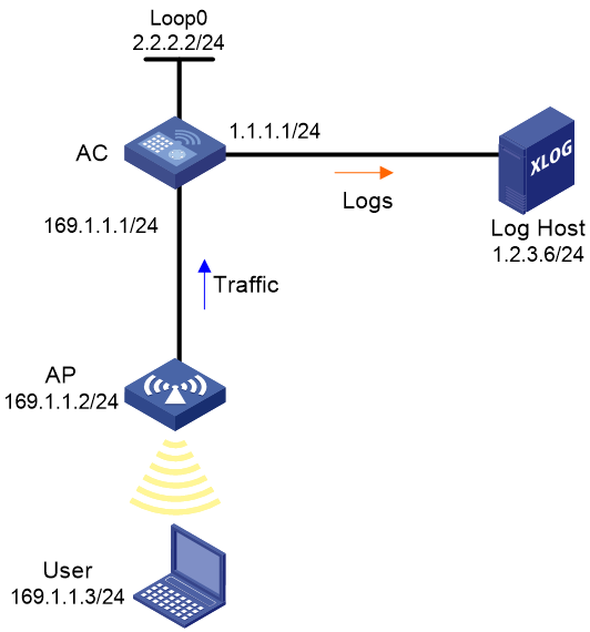
Network configuration
As shown in Figure 1, configure flow log on the AC to send flow log entries generated for the user to the log host.
Procedure
# Configure IP addresses, as shown in Figure 1. Make sure the AC, AP, user, and the log host can reach one another. (Details not shown.)
# Enable NAT logging.
<AC> system-view
[AC] nat log enable
# Enable NAT logging for session establishment events, session removal events, and active flows.
[AC] nat log flow-begin
[AC] nat log flow-end
[AC] nat log flow-active 10
# Set the flow log version to 3.0.
[AC] userlog flow export version 3
# Specify the log host at 1.2.3.6 as the destination for flow log export. Set the UDP port number to 2000.
[AC] userlog flow export host 1.2.3.6 port 2000
# Specify 2.2.2.2 as the source IP address for flow log packets.
[AC] userlog flow export source-ip 2.2.2.2
[AC] quit
Verifying the configuration
# Display the flow log configuration and statistics.
<AC> display userlog export
Flow:
Export flow log as UDP Packet.
Version: 3.0
Source ipv4 address: 2.2.2.2
Source ipv6 address:
Log load balance function: Disabled
Local time stamp: Disabled
Number of log hosts: 1
Log host 1:
Host/Port: 1.2.3.6/2000
Total logs/UDP packets exported: 112/87
Example: Configuring flow log export to a flow log host group
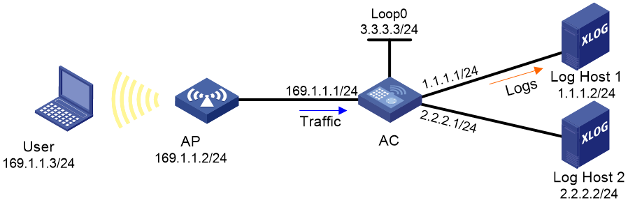
Network configuration
As shown in Figure 2, configure a flow log host group on the AC to send flow log entries generated for the user only to Log Host 1.
Procedure
# Assign IP addresses to interfaces. Make sure the AC, AP, user, and the log hosts can reach one another. (Details not shown.)
# Enable NAT logging.
<AC> system-view
[AC] nat log enable
# Enable NAT logging for session establishment events, session removal events, and active flows.
[AC] nat log flow-begin
[AC] nat log flow-end
[AC] nat log flow-active 10
# Specify Log Host 1 and Log Host 2 for flow log export.
[AC] userlog flow export host 1.1.1.2 port 2000
[AC] userlog flow export host 2.2.2.2 port 2000
# Specify 3.3.3.3 as the source IP address for flow log packets.
[AC] userlog flow export source-ip 3.3.3.3
# Create ACL 2000 to match packets sent by the user.
[AC] acl basic 2000
[AC-acl-ipv4-basic-2000] rule 1 permit source 169.1.1.3 0.0.0.0
[AC-acl-ipv4-basic-2000] quit
# Create an IPv4 flow log host group named test and specify ACL 2000 for it.
[AC] userlog host-group test acl number 2000
# Assign Log Host 1 to flow log host group test.
[AC-userlog-host-group-test] userlog host-group host flow 1.1.1.2
[AC-userlog-host-group-test] quit
Verifying the configuration
# Display information about flow log host group test.
[AC] display userlog host-group test
Userlog host-group test:
ACL number: 2000
Flow log host numbers: 1
Log host 1:
Host/port: 1.1.1.2/2000
# After the user comes online, display flow log export statistics.
[AC] display userlog export
Flow:
Export flow log as UDP Packet.
Version: 1.0
Source ipv4 address: 3.3.3.3
Source ipv6 address:
Log load balance function: Disabled
Local time stamp: Disabled
Number of log hosts: 2
Log host 1:
Host/Port: 1.1.1.2/2000
Total logs/UDP packets exported: 13/13
Log host 2:
Host/Port: 2.2.2.2/2000
Total logs/UDP packets exported: 0/0