- Table of Contents
- Related Documents
-
| Title | Size | Download |
|---|---|---|
| 05-Interface backup configuration | 164.57 KB |
Contents
Restrictions: Hardware compatibility with interface backup
Restrictions and guidelines: Interface backup configuration
Interface backup tasks at a glance
Prerequisites for configuring interface backup
Explicitly specifying backup interfaces without traffic thresholds
Using interface backup with the Track module
Configuring load-shared interface backup
Display and maintenance commands for interface backup
Interface backup configuration examples
Example: Configuring strict active/standby interface backup
Example: Configuring strict active/standby interface backup with the Track module
Example: Configuring load-shared interface backup
Configuring interface backup
About interface backup
Interface backup enables you to configure multiple backup interfaces for a Layer 3 interface to increase link availability. When the primary interface fails or is overloaded, its backup interfaces can take over or participate in traffic forwarding.
Compatible interfaces
Table 1 Interfaces that support interface backup
|
Category |
Interfaces |
Remarks |
|
Ethernet |
Layer 3 Ethernet interfaces/subinterfaces |
N/A |
|
WAN |
Eth-channel interface |
N/A |
|
Others |
Dialer interfaces Tunnel interfaces |
A dialer interface can be used as the primary interface only when it is a PPPoE client in permanent session mode. |
Backup modes
The primary interface and its backup interfaces can operate in strict active/standby mode or load sharing mode.
· Strict active/standby mode—Only one interface transmits traffic. All the other interfaces are in STANDBY state.
· Load sharing mode—Backup interfaces participate in traffic forwarding when the amount of traffic on the primary interface reaches the upper threshold. They are activated and deactivated depending on the amount of traffic.
In strict active/standby mode, traffic loss occurs when the active interface is overloaded. Load sharing mode improves link efficiency and reduces the risk of packet loss.
Strict active/standby mode
In strict active/standby mode, the primary interface always has higher priority than all backup interfaces.
· When the primary interface is operating correctly, all traffic is transmitted through the primary interface.
· When the primary interface fails, the highest-priority backup interface takes over. If the highest-priority backup interface also fails, the second highest-priority backup interface takes over, and so forth.
|
|
NOTE: If two backup interfaces have the same priority, the one configured first has preference. |
An active backup interface is always preempted by the primary interface. However, a higher-priority backup interface cannot preempt a lower-priority backup interface that has taken over the primary interface.
· The primary interface takes over when it recovers from a failure condition.
· The higher-priority backup interface cannot take over when it recovers from a failure condition while the primary interface is still down.
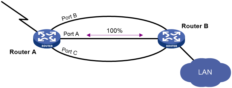
As shown in Figure 1, Port A on Router A is the primary interface. Port B (with a priority of 30) and Port C (with a priority of 20) are its backup interfaces.
· When Port A is operating correctly, all traffic is transmitted through Port A.
· When Port A fails, Port B takes over because it has higher priority than Port C. If Port B also fails, Port C takes over.
· When Port A is recovered, it preempts the active backup interface because it is the primary interface. If Port B is recovered while Port A is still down, Port B cannot preempt Port C to forward traffic.
Figure 1 Strict active/backup mode
Load sharing mode
In load sharing mode, the backup interfaces are activated to transmit traffic depending on the traffic load on the primary interface.
· When the amount of traffic on the primary interface exceeds the upper threshold, the backup interfaces are activated in descending order of priority. This action continues until the traffic drops below the upper threshold.
· When the total amount of traffic on all load-shared interfaces decreases below the lower threshold, the backup interfaces are deactivated in ascending order of priority. This action continues until the total amount of traffic exceeds the lower threshold.
· When the primary interface fails (in DOWN state), the strict active/standby mode applies. Only one backup interface can forward traffic.
The upper and lower thresholds are user configurable.
|
|
NOTE: · "Traffic" on an interface refers to the amount of incoming or outgoing traffic, whichever is higher. · If two backup interfaces have the same priority, the one configured first has preference. |
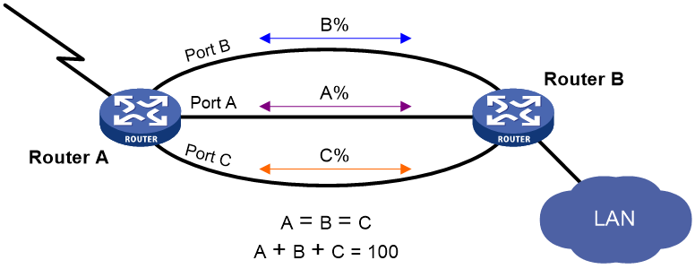
As shown in Figure 2, Port A on Router A is the primary interface. Port B (with a priority of 30) and Port C (with a priority of 20) are its backup interfaces.
· When the amount of traffic on Port A exceeds the upper threshold, Port B is activated, because it has higher priority than Port C. If the amount of traffic on Port A still exceeds the upper threshold, Port C is activated.
· When the total amount of traffic on all load-shared interfaces decreases below the lower threshold, Port C is first deactivated, because its priority is lower than Port B. If the total amount of traffic on Port A and Port B is still below the lower threshold, Port B is deactivated.
Restrictions: Hardware compatibility with interface backup
|
Hardware series |
Model |
Product code |
Interface backup compatibility |
|
WX1800H series |
WX1804H-PWR |
EWP-WX1804H-PWR-CN |
Yes |
|
WX2500H series |
WX2508H-PWR-LTE WX2510H-PWR WX2510H-F-PWR WX2540H WX2540H-F WX2560H |
EWP-WX2508H-PWR-LTE EWP-WX2510H-PWR EWP-WX2510H-F-PWR EWP-WX2540H EWP-WX2540H-F EWP-WX2560H |
Yes |
|
MAK series |
MAK204 MAK206 |
EWP-MAK204 EWP-MAK206 |
Yes |
|
WX3000H series |
WX3010H WX3010H-X-PWR WX3010H-L-PWR WX3024H WX3024H-L-PWR WX3024H-F |
EWP-WX3010H EWP-WX3010H-X-PWR EWP-WX3010H-L-PWR EWP-WX3024H EWP-WX3024H-L-PWR EWP-WX3024H-F |
WX3010H: Yes WX3010H-X-PWR: No WX3010H-L-PWR: No WX3024H: Yes WX3024H-L-PWR: No WX3024H-F: Yes |
|
WX3500H series |
WX3508H WX3510H WX3520H WX3520H-F WX3540H |
EWP-WX3508H EWP-WX3508H-F EWP-WX3510H EWP-WX3510H-F EWP-WX3520H EWP-WX3520H-F EWP-WX3540H EWP-WX3540H-F |
No |
|
WX5500E series |
WX5510E WX5540E |
EWP-WX5510E EWP-WX5540E |
No |
|
WX5500H series |
WX5540H WX5560H WX5580H |
EWP-WX5540H EWP-WX5560H EWP-WX5580H |
No |
|
Access controller modules |
LSUM1WCME0 EWPXM1WCME0 LSQM1WCMX20 LSUM1WCMX20RT LSQM1WCMX40 LSUM1WCMX40RT EWPXM2WCMD0F EWPXM1MAC0F |
LSUM1WCME0 EWPXM1WCME0 LSQM1WCMX20 LSUM1WCMX20RT LSQM1WCMX40 LSUM1WCMX40RT EWPXM2WCMD0F EWPXM1MAC0F |
No |
|
Hardware series |
Model |
Product code |
Interface backup compatibility |
|
WX1800H series |
WX1804H-PWR WX1810H-PWR WX1820H WX1840H |
EWP-WX1804H-PWR EWP-WX1810H-PWR EWP-WX1820H EWP-WX1840H-GL |
Yes |
|
WX3800H series |
WX3820H WX3840H |
EWP-WX3820H-GL EWP-WX3840H-GL |
No |
|
WX5800H series |
WX5860H |
EWP-WX5860H-GL |
No |
Restrictions and guidelines: Interface backup configuration
When you configure interface backup, follow these restrictions and guidelines:
· The device supports up to 10 primary interfaces.
· An interface can be configured as a backup only for one interface.
· An interface cannot be both a primary and backup interface.
· The strict active/standby mode and load sharing mode cannot be configured at the same time.
Interface backup tasks at a glance
To configure interface backup, perform the following tasks:
· Configuring strict active/standby interface backup
Choose one of the following tasks:
¡ Explicitly specifying backup interfaces without traffic thresholds
Use this method if you want to monitor the interface state of the primary interface for a switchover to occur.
¡ Using interface backup with the Track module
Use this method if you want to monitor any other state, such as the link state of the primary interface.
· Configuring load-shared interface backup
Prerequisites for configuring interface backup
Make sure the primary and backup interfaces have routes to the destination network.
Explicitly specifying backup interfaces without traffic thresholds
About this task
Perform this task if you want to monitor the interface state of the primary interface for a switchover to occur. For the primary and backup interfaces to operate in strict active/standby mode, do not specify the traffic thresholds on the primary interface. If the traffic thresholds are configured, the interfaces will operate in load sharing mode.
You can assign priority to backup interfaces. When the primary interface fails, the backup interfaces are activated in descending order of priority, with the highest-priority interface activated first. If two backup interfaces have the same priority, the one configured first has preference.
To prevent link flapping from causing frequent interface switchovers, you can configure the following switchover delay timers:
· Up delay timer—Number of seconds that the primary or backup interface must wait before it can come up.
· Down delay timer—Number of seconds that the active primary or backup interface must wait before it is set to down state.
When the link of the active interface fails, the interface state does not change immediately. Instead, a down delay timer starts. If the link recovers before the timer expires, the interface state does not change. If the link is still down when the timer expires, the interface state changes to down.
Procedure
1. Enter system view.
system-view
2. Enter interface view.
interface interface-type interface-number
This interface must be the primary interface.
3. Specify a backup interface.
backup interface interface-type interface-number [ priority ]
By default, an interface does not have any backup interfaces.
Repeat this command to specify up to three backup interfaces for the interface.
4. Set the switchover delay timers.
backup timer delay up-delay down-delay
By default, the up and down delay timers are both 5 seconds.
Using interface backup with the Track module
About this task
Perform this task if you want to monitor any other state, such as the link state of the primary interface. To use interface backup with the Track module to provide strict active/standby backup for a primary interface:
· Configure a track entry to monitor state information of the primary interface. For example, monitor its link state.
· Associate the track entry with a backup interface.
Interface backup changes the state of the backup interface in response to the track entry state, as shown in Table 2.
Table 2 Action on the backup interface in response to the track entry state change
|
Track entry state |
State of the monitored primary link |
Action on the backup interface |
|
Positive |
The primary link is operating correctly. |
Places the backup interface in STANDBY state. |
|
Negative |
The primary link has failed. |
Activates the backup interface to take over. |
|
NotReady |
The primary link is not monitored. This situation occurs when the track module or the monitoring module is not ready, for example, because the Track module is restarting or the monitoring settings are incomplete. In this situation, interface backup cannot obtain information about the primary link from the track module. |
· If the track entry state stays in NotReady state after it is created, interface backup does not change the state of the backup interface. · If the track entry state changes to NotReady from Positive or Negative, the backup interface changes back to the forwarding state before it was used for interface backup. |
For more information about configuring a track entry, see "Configuring Track."
Restrictions and guidelines
· You can associate an interface with only one track entry.
· You can create the associated track entry before or after the association. The association takes effect after the track entry is created.
· To maintain performance, limit the number of associations to 64.
Procedure
1. Enter system view.
system-view
2. Enter interface view.
interface interface-type interface-number
This interface must be the interface you are using as a backup.
3. Associate the interface with a track entry.
backup track track-entry-number
By default, an interface is not associated with a track entry.
Configuring load-shared interface backup
About this task
To implement load-balanced interface backup, you must configure the traffic thresholds on the primary interface. Interface backup regularly compares the amount of traffic with the thresholds to determine whether to activate or deactivate a backup interface. The traffic polling interval is user configurable.
You can assign priority to backup interfaces.
· When the amount of traffic on the primary interface exceeds the upper threshold, the backup interfaces are activated in descending order of priority.
· When the total amount of traffic on all load-shared interfaces decreases below the lower threshold, the backup interfaces are deactivated in ascending order of priority.
If two backup interfaces have the same priority, the one configured first has preference.
Procedure
1. Enter system view.
system-view
2. Enter interface view.
interface interface-type interface-number
You must enter the view of the primary interface.
3. Configure a backup interface for the interface.
backup interface interface-type interface-number [ priority ]
By default, an interface does not have any backup interfaces.
Repeat this command to specify up to three backup interfaces.
4. Set backup load sharing thresholds.
backup threshold upper-threshold lower-threshold
By default, no traffic thresholds are configured.
5. Set the traffic polling interval.
backup timer flow-check interval
The default interval is 30 seconds.
Display and maintenance commands for interface backup
Execute display commands in any view.
|
Command |
|
|
Display traffic statistics for load-shared interfaces. |
display interface-backup statistics |
|
Display the status of primary and backup interfaces. |
display interface-backup state |
Interface backup configuration examples
Example: Configuring strict active/standby interface backup
Network configuration
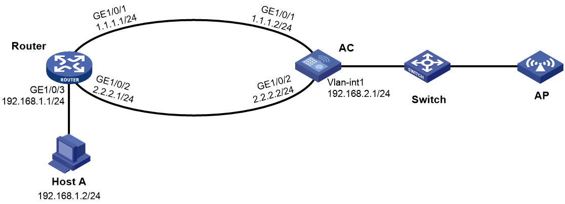
As shown in Figure 3:
· Specify GigabitEthernet 1/0/2 on the AC to back up GigabitEthernet 1/0/1.
· Set the up and down delay timers to 10 seconds for the backup interface.
Procedure
1. Assign IP addresses to the interfaces, as shown in Figure 3. (Details not shown.)
2. Configure static routes:
# On the router, configure static routes to 192.168.2.0/24 through the primary and backup interfaces.
<Router> system-view
[Router] ip route-static 192.168.2.0 24 gigabitethernet 1/0/1 1.1.1.2
[Router] ip route-static 192.168.2.0 24 gigabitethernet 1/0/2 2.2.2.2
# On the AC, configure static routes to 192.168.1.0/24.
<AC> system-view
[AC] ip route-static 192.168.1.0 24 gigabitethernet 1/0/1 1.1.1.1
[AC] ip route-static 192.168.1.0 24 gigabitethernet 1/0/2 2.2.2.1
3. On the AC, configure backup interfaces and switchover delays:
# Specify GigabitEthernet 1/0/2 to back up GigabitEthernet 1/0/1.
[AC] interface gigabitethernet 1/0/1
[AC-GigabitEthernet1/0/1] backup interface gigabitethernet 1/0/2
# Set both up and down delay timers to 10 seconds.
[AC-GigabitEthernet1/0/1] backup timer delay 10 10
Verifying the configuration
# Display states of the primary and backup interfaces.
[AC-GigabitEthernet1/0/1] display interface-backup state
Interface: GE1/0/1
UpDelay: 10 s
DownDelay: 10 s
State: UP
Backup interfaces:
GE1/0/2 Priority: 0 State: STANDBY
The output shows that GigabitEthernet 1/0/1 is in UP state and the backup interface is in STANDBY state.
# Shut down the primary interface GigabitEthernet 1/0/1.
[AC-GigabitEthernet1/0/1] shutdown
# Verify that the backup interface GigabitEthernet 1/0/2 comes up 10 seconds after the primary interface goes down.
[AC-GigabitEthernet1/0/1] display interface-backup state
Interface: GE1/0/1
UpDelay: 10 s
DownDelay: 10 s
State: DOWN
Backup interfaces:
GE1/0/2 Priority: 0 State: UP
Example: Configuring strict active/standby interface backup with the Track module
Network configuration
As shown in Figure 4, configure a track entry to monitor the link state of GigabitEthernet 1/0/1. When the link of GigabitEthernet 1/0/1 fails, the backup interface GigabitEthernet 1/0/2 comes up to take over.

Procedure
1. Assign IP addresses to the interfaces, as shown in Figure 4. (Details not shown.)
2. Configure static routes:
# On the router, configure static routes to 192.168.2.0/24 through the primary and backup interfaces.
<Router> system-view
[Router] ip route-static 192.168.2.0 24 gigabitethernet 1/0/1 1.1.1.2
[Router] ip route-static 192.168.2.0 24 gigabitethernet 1/0/2 2.2.2.2
# On the AC, configure static routes to 192.168.1.0/24.
<AC> system-view
[AC] ip route-static 192.168.1.0 24 gigabitethernet 1/0/1 1.1.1.1
[AC] ip route-static 192.168.1.0 24 gigabitethernet 1/0/2 2.2.2.1
3. On the AC, configure Track settings:
# Configure track entry 1 to monitor the link state of GigabitEthernet 1/0/1.
[AC] track 1 interface gigabitethernet 1/0/1
# Associate track entry 1 with the backup interface GigabitEthernet 1/0/2.
[AC] interface gigabitethernet 1/0/2
[AC-GigabitEthernet1/0/2] backup track 1
[AC-GigabitEthernet1/0/2] quit
Verifying the configuration
# Verify that the backup interface GigabitEthernet 1/0/2 is in STANDBY state while the primary link is operating correctly.
[AC] display interface-backup state
IB Track Information:
GE1/0/2 Track: 1 State: STANDBY
# Shut down the primary interface GigabitEthernet 1/0/1.
[AC] interface gigabitethernet 1/0/1
[AC-GigabitEthernet1/0/1] shutdown
# Verify that the backup interface GigabitEthernet 1/0/2 comes up after the primary link goes down.
[AC-GigabitEthernet1/0/1] display interface-backup state
IB Track Information:
GE1/0/2 Track: 1 State: UP
Example: Configuring load-shared interface backup
Network configuration
As shown in Figure 5:
· Configure GigabitEthernet 1/0/2 on the router to back up the primary interface GigabitEthernet 1/0/1.
· On the primary interface:
¡ Specify the interface bandwidth used for traffic load calculation.
¡ Set the upper and lower thresholds to 80 and 20, respectively.

Procedure
1. Assign IP addresses to the interfaces, as shown in Figure 5. (Details not shown.)
2. Configure static routes:
# On the router, configure static routes to 192.168.2.0/24 through the primary and backup interfaces.
<Router> system-view
[Router] ip route-static 192.168.2.0 24 gigabitethernet 1/0/1 1.1.1.2
[Router] ip route-static 192.168.2.0 24 gigabitethernet 1/0/2 2.2.2.2
# On the AC, configure static routes to 192.168.1.0/24.
<AC> system-view
[AC] ip route-static 192.168.1.0 24 gigabitethernet 1/0/1 1.1.1.1
[AC] ip route-static 192.168.1.0 24 gigabitethernet 1/0/2 2.2.2.1
3. On the AC, configure backup interfaces and traffic thresholds:
# Specify GigabitEthernet 1/0/2 to back up GigabitEthernet 1/0/1.
[AC] interface gigabitethernet 1/0/1
[AC-GigabitEthernet1/0/1] backup interface gigabitethernet 1/0/2
# Set the expected bandwidth to 10000 kbps on the primary interface.
[AC-GigabitEthernet1/0/1] bandwidth 10000
# Set the upper and lower thresholds to 80 and 20, respectively.
[AC-GigabitEthernet1/0/1] backup threshold 80 20
Verifying the configuration
# Display traffic statistics for load-shared interfaces.
[AC-GigabitEthernet1/0/1] display interface-backup statistics
Interface: GigabitEthernet1/0/1
Statistics interval: 30 s
Bandwidth: 10000000 bps
PrimaryTotalIn: 102 bytes
PrimaryTotalOut: 108 bytes
PrimaryIntervalIn: 102 bytes
PrimaryIntervalOut: 108 bytes
Primary used bandwidth: 28 bps
TotalIn: 102 bytes
TotalOut: 108 bytes
TotalIntervalIn: 102 bytes
TotalIntervalOut: 108 bytes
Total used bandwidth: 28 bps
The output shows that the upper traffic threshold has not been exceeded. All traffic is transmitted through the primary interface GigabitEthernet 1/0/1.
# Verify that the backup interface is in STANDBY state because the upper threshold has not been exceeded.
[AC-GigabitEthernet1/0/1] display interface-backup state
Interface: GE1/0/1
UpDelay: 5 s
DownDelay: 5 s
Upper threshold: 80
Lower threshold: 20
State: UP
Backup interfaces:
GE1/0/2 Priority: 0 State: STANDBY
# Increase the incoming or outgoing traffic rate to be higher than 8000 kbps (80% of the specified bandwidth) on the primary interface. (Details not shown.)
# Verify that the backup interface GigabitEthernet 1/0/2 comes up to participate in traffic forwarding.
[AC-GigabitEthernet1/0/1] display interface-backup state
Interface: GE1/0/1
UpDelay: 5 s
DownDelay: 5 s
Upper threshold: 80
Lower threshold: 20
State: UP
Backup interfaces:
GE1/0/2 Priority: 0 State: UP