- Table of Contents
- Related Documents
-
| Title | Size | Download |
|---|---|---|
| 01-WLAN high availability configuration | 228.71 KB |
Restrictions and guidelines: Dual-link backup configuration
Dual-link backup tasks at a glance
Setting AP connection priority and specifying a backup AC
Configuring master CAPWAP tunnel preemption
Dual-link backup configuration examples
Example: Configuring dual-link backup
Restrictions: Hardware compatibility with AP load balancing and backup
Setting the keepalive timeout for AP backup
Display and maintenance commands for AP backup
AP backup configuration examples
Example: Configuring AP backup
Restrictions: Hardware compatibility with client backup
Restrictions and guidelines: Client backup configuration
Prerequisites for client backup
Setting the client backup delay
Display and maintenance commands for client backup
Client backup configuration examples
Example: Configuring client backup
Configuring WLAN uplink detection
Restrictions and guidelines: WLAN uplink detection
Configuring WLAN uplink detection
WLAN uplink detection configuration examples
Example: Configuring WLAN uplink detection
Configuring dual-link backup
About dual-link backup
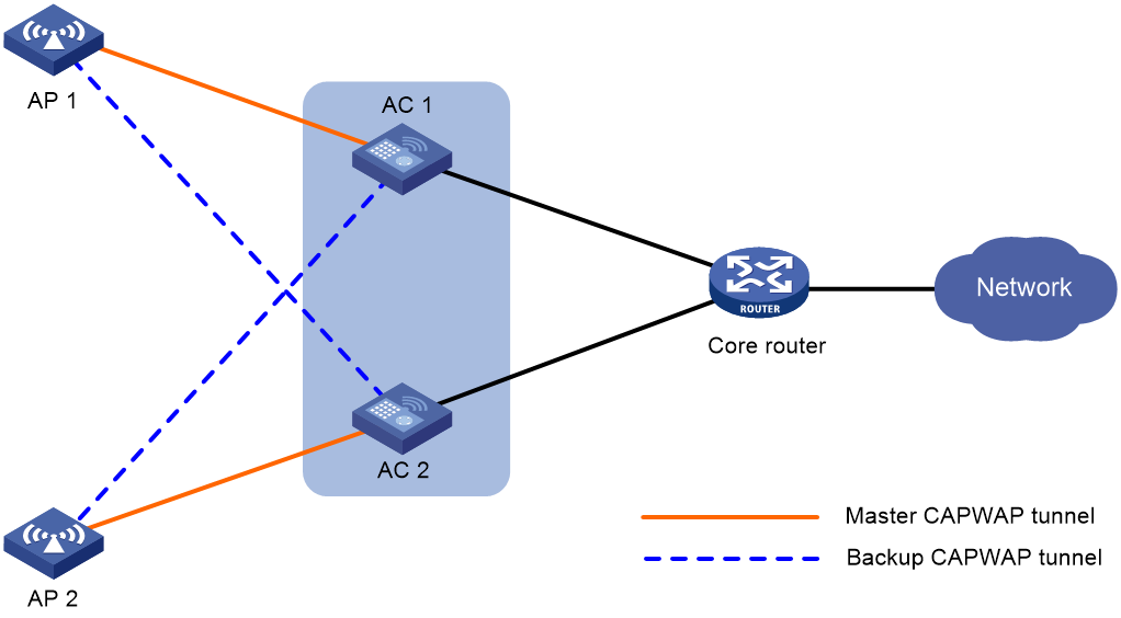
Dual-link backup enables two ACs to back up each other to reduce risks of service interruption caused by single-AC failures.
Dual-link backup is applicable to networks that are service continuity insensitive.
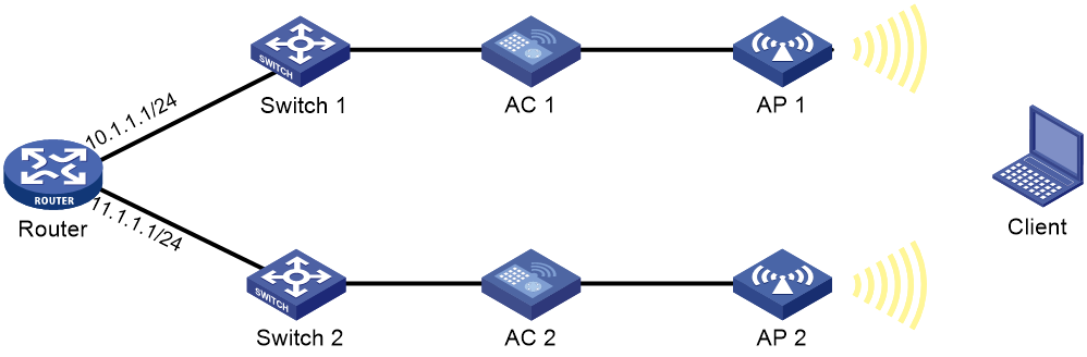
Figure 1 Network diagram for dual-link backup
Restrictions and guidelines: Dual-link backup configuration
For the dual-link backup feature to function correctly, configure auto AP or manual APs on the two ACs. The manual AP configuration must be identical on both ACs. For more information, see managing APs in AP and WT Management Configuration Guide.
You can configure APs by using the following methods:
· Configure APs one by one in AP view.
· Assign APs to an AP group and configure the AP group in AP group view.
· Configure all APs in global configuration view.
For an AP, the settings made in these views for the same parameter take effect in descending order of AP view, AP group view, and global configuration view.
Dual-link backup tasks at a glance
To configure dual-link backup, perform the following tasks:
1. Setting AP connection priority and specifying a backup AC
2. (Optional.) Configuring master CAPWAP tunnel preemption
Setting AP connection priority and specifying a backup AC
About this task
Set a higher AP connection priority for the master AC to ensure that APs can associate with the master AC first.
After an AP establishes a CAPWAP tunnel with the master AC, the AP will establish a backup CAPWAP tunnel with the specified backup AC.
Procedure
1. Enter system view.
system-view
2. Enter AP view or AP group view.
¡ Enter AP view.
wlan ap ap-name
¡ Enter AP group view.
wlan ap-group group-name
3. Set the AP connection priority.
priority priority
By default:
¡ In AP view, an AP uses the configuration in AP group view.
¡ In AP group view, the AP connection priority is 4.
4. Specify a backup AC.
backup-ac { ip ipv4-address | ipv6 ipv6-address }
By default:
¡ In AP view, an AP uses the configuration in AP group view.
¡ In AP group view, no backup AC is specified.
Configuring master CAPWAP tunnel preemption
About this task
This feature enables a backup CAPWAP tunnel to become a master tunnel after the specified delay time if the backup AC has higher AP connection priority than the master AC.
Procedure
1. Enter system view.
system-view
2. Enter AP view, AP group view, or global configuration view.
¡ Enter AP view.
wlan ap ap-name
¡ Enter AP group view.
wlan ap-group group-name
¡ Enter global configuration view.
wlan global-configuration
3. Configure master CAPWAP tunnel preemption.
wlan tunnel-preempt { disable | enable }
By default:
¡ In AP view, an AP uses the configuration in AP group view. If no configuration exists in AP group view, the AP uses the configuration in global configuration view.
¡ In AP group view, an AP uses the configuration in global configuration view.
¡ In global configuration view, master CAPWAP tunnel preemption is disabled.
Dual-link backup configuration examples
The AP models and serial numbers in this document are used only as examples. Support for AP models and serial numbers depends on the AC model.
Example: Configuring dual-link backup
Network configuration
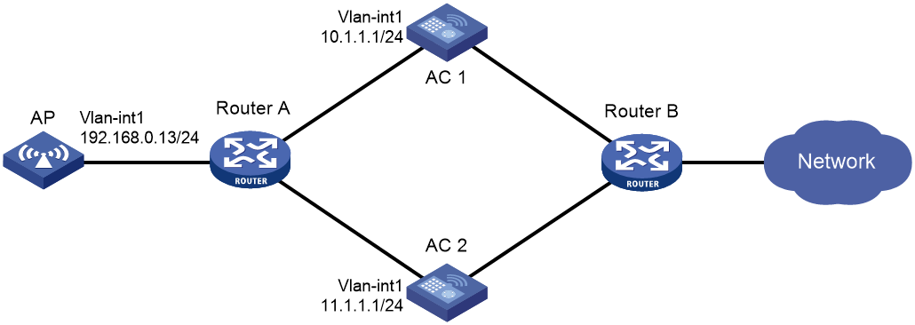
As shown in Figure 2, configure AC 1 to act as the master AC and AC 2 as the backup AC. When AC 1 fails and AC 2 takes over, the AP can communicate through AC 2. Configure the master CAPWAP tunnel preemption feature on the two ACs so that the AP reconnects to AC 1 when AC 1 recovers.
Procedure
1. Configure AC 1:
# Create VLAN-interface 1 and assign an IP address to it.
<AC1> system-view
[AC1] interface vlan-interface 1
[AC1-Vlan-interface1] ip address 10.1.1.1 24
[AC1-Vlan-interface1] quit
# Create an AP named ap1, and specify the AP model and serial ID. Set the AP connection priority to 7.
[AC1] wlan ap ap1 model WA6320
[AC1-wlan-ap-ap1] serial-id 219801A28N819CE0002T
[AC1-wlan-ap-ap1] priority 7
[AC1-wlan-ap-ap1] backup-ac ip 11.1.1.1
# Enable master CAPWAP tunnel preemption.
[AC1-wlan-ap-ap1] wlan tunnel-preempt enable
[AC1-wlan-ap-ap1] quit
2. Configure AC 2:
# Create VLAN-interface 1 and assign an IP address to it.
<AC2> system-view
[AC2] interface Vlan-interface 1
[AC2-Vlan-interface1] ip address 11.1.1.1 24
[AC2-Vlan-interface1] quit
# Create an AP named ap1, and specify the AP model and serial ID. Set the AP connection priority to 5.
[AC2] wlan ap ap1 model WA6320
[AC2-wlan-ap-ap1] serial-id 219801A28N819CE0002T
[AC2-wlan-ap-ap1] priority 5
# Specify a backup AC.
[AC2-wlan-ap-ap1] backup-ac ip 10.1.1.1
# Enable master CAPWAP tunnel preemption.
[AC2-wlan-ap-ap1] wlan tunnel-preempt enable
[AC2-wlan-ap-ap1] quit
Verifying the configuration
# Get the AP online on AC 1. (Details not shown.)
# Shut down VLAN-interface 1 on AC 1 and wait no longer than 3 minutes, during which service interruption occurs. (Details not shown.)
# Verify that the AP comes online on AC 2 and the AP state is R/M on AC 2. (Details not shown.)
# Bring up VLAN-interface 1 on AC 1. (Details not shown.)
# Verify that the AP comes online on AC 1 again and the AP state is R/M on AC 1 and R/B in AC 2. (Details not shown.)
Configuring AP backup
About AP backup
AP backup use IRF to enable multiple ACs to form an IRF fabric to ensure centralized AP management and avoid wireless service interruption in case of AC failures.
AC roles
An AC has the following roles:
|
Role |
Description |
|
Master AC |
Master in an IRF fabric. A master AC manages the entire IRF fabric. |
|
Subordinate AC |
Subordinate in an IRF fabric. A subordinate AC processes services, forwards packets, and acts as a backup for the master AC. When the master AC fails, the system automatically elects a new master AC from the subordinate ACs in the IRF fabric. |
|
Active AC |
An AC that can establish CAPWAP tunnels with APs. The master AC is always an active AC. |
|
Non-active AC |
An AC that cannot establish CAPWAP tunnels with APs. Non-active ACs can only be subordinate ACs. When an active AC fails, a non-active AC will be elected as an active AC. |
|
Directly connected AC |
An AC that receives the first packet from an AP when the AP launches a CAPWAP tunnel establishment process. |
|
Non-directly connected AC |
An AC that does not receive the first packet from an AP when the AP launches a CAPWAP tunnel establishment process. |
AP backup and recovery
AP backup enables the active AC (master AC) in an IRF fabric to synchronize information about connected APs to all the non-active ACs. When the active AC fails, one of the non-active ACs becomes active to provide services, ensuring service continuity.
Restrictions: Hardware compatibility with AP load balancing and backup
|
Hardware series |
Model |
Product code |
AP backup compatibility |
|
WX1800H series |
WX1804H |
EWP-WX1804H-PWR-CN |
No |
|
WX2500H series |
WX2508H-PWR-LTE WX2510H WX2510H-F WX2540H WX2540H-F WX2560H |
EWP-WX2508H-PWR-LTE EWP-WX2510H-PWR EWP-WX2510H-F-PWR EWP-WX2540H EWP-WX2540H-F EWP-WX2560H |
No |
|
MAK series |
MAK204 MAK206 |
EWP-MAK204 EWP-MAK206 |
No |
|
WX3000H series |
WX3010H WX3010H-X WX3010H-L WX3024H WX3024H-L WX3024H-F |
EWP-WX3010H EWP-WX3010H-X-PWR EWP-WX3010H-L-PWR EWP-WX3024H EWP-WX3024H-L-PWR EWP-WX3024H-F |
No |
|
WX3500H series |
WX3508H WX3510H WX3520H WX3520H-F WX3540H |
EWP-WX3508H EWP-WX3510H EWP-WX3520H EWP-WX3520H-F EWP-WX3540H |
Yes |
|
WX5500E series |
WX5510E WX5540E |
EWP-WX5510E EWP-WX5540E |
Yes |
|
WX5500H series |
WX5540H WX5560H WX5580H |
EWP-WX5540H EWP-WX5560H EWP-WX5580H |
Yes |
|
Access controller modules |
LSUM1WCME0 EWPXM1WCME0 LSQM1WCMX20 LSUM1WCMX20RT LSQM1WCMX40 LSUM1WCMX40RT EWPXM2WCMD0F EWPXM1MAC0F |
LSUM1WCME0 EWPXM1WCME0 LSQM1WCMX20 LSUM1WCMX20RT LSQM1WCMX40 LSUM1WCMX40RT EWPXM2WCMD0F EWPXM1MAC0F |
Yes |
|
Hardware series |
Model |
Product code |
AP load balancing and backup compatibility |
|
WX1800H series |
WX1804H WX1810H WX1820H WX1840H |
EWP-WX1804H-PWR EWP-WX1810H-PWR EWP-WX1820H EWP-WX1840H-GL |
No |
|
WX3800H series |
WX3820H WX3840H |
EWP-WX3820H-GL EWP-WX3840H-GL |
No |
|
WX5800H series |
WX5860H |
EWP-WX5860H-GL |
No |
AP backup tasks at a glance
To configure AP backup, perform the following tasks:
2. (Optional.) Setting the keepalive timeout for AP backup
Prerequisites for AP backup
Before configuring AP backup, set up an IRF fabric for the target ACs. For information about IRF, see "Configuring an IRF fabric."
Enabling AP backup
About this task
This feature enables the active AC to synchronize information about connected APs to all the non-active ACs. When the active AC fails, one of the non-active AC becomes active to provide services.
Restrictions and guidelines
Disabling this feature removes backup AP information from all ACs.
Procedure
1. Enter system view.
system-view
2. Enable AP backup.
wlan ap-backup hot-backup enable global
By default, AP backup is disabled.
Setting the keepalive timeout for AP backup
About this task
By default, member ACs use the IRF hello packet mechanism to identify AC status. You can set the keepalive timeout for AP backup as required. Each IRF member AC periodically broadcasts keepalive packets and determines that a member fails If no keepalive packets are received from that member within the keepalive timeout time.
· If the master AC fails, the system will automatically select a new master AC from the subordinate ACs.
· If a subordinate AC fails, the master AC will record the AC failure and transfer services on the subordinate AC to another subordinate AC.
Procedure
1. Enter system view.
system-view
2. Set the keepalive timeout for AP backup.
wlan hot-backup keepalive timeout milliseconds
The default setting is 10000 milliseconds.
Display and maintenance commands for AP backup
Execute display commands in any view.
|
Task |
Command |
|
Display AP backup status for all IRF member ACs. |
display wlan ap backup multislot |
AP backup configuration examples
The AP models and serial numbers in this document are used only as examples. Support for AP models and serial numbers depends on the AC model.
Example: Configuring AP backup
Network configuration
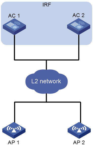
As shown in Figure 3, AC 1 and AC 2 form an IRF fabric. To keep APs online in case of AC failures, configure one AC as the active AC and configure the other AC to back up AP information.
Procedure
# Set up an IRF fabric. (Details not shown.)
For more information, see "Configuring an IRF fabric."
# Configure wireless services on the IRF fabric. (Details not shown.)
For more information, see WLAN Access Configuration Guide.
# Enable AP backup.
[AC] wlan ap-backup hot-backup enable global
Verifying the configuration
Verify that the AP is still online after the active AC fails. (Details not shown.)
Configuring client backup
About client backup
Client backup enables IRF member ACs to backup client information with each other to keep clients online in case of AC failures.
Client backup must work with AP backup. After both features are enabled, active ACs back up connected AP and client information to other member ACs. When an active AC fails, the master AC will select another AC in the IRF fabric to recover information of AP and clients connected to the failed AC. For information about AP backup and AC selection, see "Configuring AP backup."
Restrictions: Hardware compatibility with client backup
|
Hardware series |
Model |
Product code |
Client backup compatibility |
|
WX1800H series |
WX1804H |
EWP-WX1804H-PWR-CN |
No |
|
WX2500H series |
WX2508H-PWR-LTE WX2510H WX2510H-F WX2540H WX2540H-F WX2560H |
EWP-WX2508H-PWR-LTE EWP-WX2510H-PWR EWP-WX2510H-F-PWR EWP-WX2540H EWP-WX2540H-F EWP-WX2560H |
No |
|
MAK series |
MAK204 MAK206 |
EWP-MAK204 EWP-MAK206 |
No |
|
WX3000H series |
WX3010H WX3010H-X WX3010H-L WX3024H WX3024H-L WX3024H-F |
EWP-WX3010H EWP-WX3010H-X-PWR EWP-WX3010H-L-PWR EWP-WX3024H EWP-WX3024H-L-PWR EWP-WX3024H-F |
No |
|
WX3500H series |
WX3508H WX3510H WX3520H WX3520H-F WX3540H |
EWP-WX3508H EWP-WX3510H EWP-WX3520H EWP-WX3520H-F EWP-WX3540H |
Yes |
|
WX5500E series |
WX5510E WX5540E |
EWP-WX5510E EWP-WX5540E |
Yes |
|
WX5500H series |
WX5540H WX5560H WX5580H |
EWP-WX5540H EWP-WX5560H EWP-WX5580H |
Yes |
|
Access controller modules |
LSUM1WCME0 EWPXM1WCME0 LSQM1WCMX20 LSUM1WCMX20RT LSQM1WCMX40 LSUM1WCMX40RT EWPXM2WCMD0F EWPXM1MAC0F |
LSUM1WCME0 EWPXM1WCME0 LSQM1WCMX20 LSUM1WCMX20RT LSQM1WCMX40 LSUM1WCMX40RT EWPXM2WCMD0F EWPXM1MAC0F |
Yes |
|
Hardware series |
Model |
Product code |
Client backup compatibility |
|
WX1800H series |
WX1804H WX1810H WX1820H WX1840H |
EWP-WX1804H-PWR EWP-WX1810H-PWR EWP-WX1820H EWP-WX1840H-GL |
No |
|
WX3800H series |
WX3820H WX3840H |
EWP-WX3820H-GL EWP-WX3840H-GL |
No |
|
WX5800H series |
WX5860H |
EWP-WX5860H-GL |
No |
Restrictions and guidelines: Client backup configuration
Active ACs back up client information only for clients that come online after client backup is enabled. Disabling client backup deletes client backup information from all member ACs.
Prerequisites for client backup
Enable AP backup.
Enabling client backup
1. Enter system view.
system-view
2. Enable client backup.
wlan client-backup hot-backup enable
By default, client backup is disabled.
Setting the client backup delay
Restrictions and guidelines
This feature takes effect only when client backup is enabled.
This feature takes effect only on clients that come online after the client backup delay is set.
If an active/standby switchover occurs during the delay time, online clients whose information has not been backed up will be logged off and need to come online again. An active/standby switchover can be triggered by a restart of the active AC process.
Procedure
1. Enter system view.
system-view
2. Set the client backup delay.
wlan client-backup hot-backup delay delay-time
By default, the client backup delay is 60 seconds.
Display and maintenance commands for client backup
Execute display commands in any view.
|
Task |
Command |
|
Display backup information about 802.1X clients associated with the specified IRF member device. |
display dot1x connection-backup [ ap ap-name [ radio radio-id ] ] slot slot-number |
|
Display backup information about MAC authentication clients associated with the specified IRF member device. |
display mac-authentication connection-backup [ ap ap-name [ radio radio-id ] ] slot slot-number |
|
Display client backup information for the specified IRF member device. |
display wlan client-backup [ ap ap-name [ radio radio-id ] | mac-address mac-address ] [ verbose ] [ slot slot-number ] |
Client backup configuration examples
The AP models and serial numbers in this document are used only as examples. Support for AP models and serial numbers depends on the AC model.
Example: Configuring client backup
Network configuration
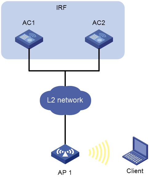
As shown in Figure 4, AC 1 and AC 2 form an IRF fabric. To keep clients online in case of AC failures, configure one AC as the active AC and configure the other AC to back up AP information and client information.
Procedure
# Set up an IRF fabric. (Details not shown.)
For more information, see "Configuring an IRF fabric."
# Configure wireless services on the IRF fabric. (Details not shown.)
For more information, see WLAN Access Configuration Guide.
# Enable AP backup.
[AC] wlan ap-backup hot-backup enable global
# Enable client backup.
[AC] wlan client-backup hot-backup enable
Verifying the configuration
# Verify that AC 2 has backed up client information.
[AC] display wlan client-backup slot 2
Total number of clients: 1
MAC address Username AP name RID IP address IPv6 address VLAN
7854-2e1c-c59e user ap1 1 1.1.1.1 1::2:0:0:3 1
Configuring WLAN uplink detection
About WLAN uplink detection
When the uplink of an AC fails, clients cannot access external networks through the APs that are connected to the AC. WLAN uplink detection associates the uplink state of an AC with the radio state of the connected APs. When the uplink fails, the AC disables the radios of the APs. When the uplink recovers, the AC enables the radios of the APs. The association ensures that clients can associate with APs connected to another AC when the uplink of an AC fails.
This feature collaborates with a detection module and the Track module to function.
· When the track entry is in Positive state, the AC enables the radios of the connected APs.
· When the track entry is in Negative state, the AC disables the radios of the connected APs.
· When the track entry is in Invalid state, the AC does not change the radio state of the connected APs.
For more information about the track module, see "Configuring Track."
Restrictions and guidelines: WLAN uplink detection
For the WLAN uplink detection feature to function correctly, configure a detection module to detect the uplink state, and associate a track entry with the detection module. For more information, see "Configuring Track."
Configuring WLAN uplink detection
1. Enter system view.
system-view
2. Associate a track entry with the WLAN uplink detection feature.
wlan uplink track track-entry-number
By default, WLAN uplink detection is not associated with any track entry.
WLAN uplink detection configuration examples
Example: Configuring WLAN uplink detection
Network configuration
As shown in Figure 5, use an NQA operation to test the reachability of each AC's uplink. Configure WLAN uplink detection on each AC so that clients can associate with the AP connected to another AC when the uplink of an AC fails.
Procedure
1. Configure AC 1:
# Create an ICMP echo operation.
<AC1> system-view
[AC1] nqa entry admin test
[AC1-nqa-admin-test] type icmp-echo
# Specify 10.1.1.1 as the destination IP address of ICMP echo requests.
[AC1-nqa-admin-test-icmp-echo] destination ip 10.1.1.1
# Configure the ICMP echo operation to repeat every 1000 milliseconds.
[AC1-nqa-admin-test-icmp-echo] frequency 1000
# Create reaction entry 1. If the number of consecutive probe failures reaches 5, collaboration is triggered.
[AC1-nqa-admin-test-icmp-echo] reaction 1 checked-element probe-fail threshold-type consecutive 5 action-type trigger-only
[AC1-nqa-admin-test-icmp-echo] quit
# Start the ICMP echo operation.
[AC1] nqa schedule admin test start-time now lifetime forever
# Configure track entry 1, and associate it with reaction entry 1 of the NQA operation (with administrator admin and operation tag test).
[AC1] track 1 nqa entry admin test reaction 1
[AC1-track-1] quit
# Associate track entry 1 with WLAN uplink detection.
[AC1] wlan uplink track 1
[AC1] quit
2. Configure AC 2:
# Create an ICMP echo operation.
<AC2> system-view
[AC2] nqa entry admin test
[AC2-nqa-admin-test] type icmp-echo
# Specify 11.1.1.1 as the destination IP address of ICMP echo requests.
[AC2-nqa-admin-test-icmp-echo] destination ip 11.1.1.1
# Create reaction entry 1. If the number of consecutive probe failures reaches 5, collaboration is triggered.
[AC2-nqa-admin-test-icmp-echo] reaction 1 checked-element probe-fail threshold-type consecutive 5 action-type trigger-only
[AC2-nqa-admin-test-icmp-echo] quit
# Start the ICMP echo operation.
[AC2] nqa schedule admin test start-time now lifetime forever
# Configure track entry 1, and associate it with reaction entry 1 of the NQA operation (with administrator admin and operation tag test).
[AC2] track 1 nqa entry admin test reaction 1
# Associate track entry 1 with WLAN uplink detection.
[AC2] wlan uplink track 1
[AC2] quit
Verifying the configuration
This example uses AC 1 to verify the configuration.
1. Verify that the radio state of AP 1 is Up when the state of track entry 1 is Positive:
# Display information about track entry 1.
<AC1> display track 1
Track ID: 1
State: Positive
Duration: 0 days 1 hours 5 minutes 48 seconds
Notification delay: Positive 0, Negative 0 (in seconds)
Tracked object:
NQA entry: admin test
Reaction: 1
# Display detailed information about AP ap1.
<AC1> display wlan ap name ap1 verbose
AP name : ap1
AP ID : 1
AP group name : default-group
State : Run
Backup type : Idle
Backup Type : Master
Online time : 0 days 2 hours 25 minutes 12 seconds
System up time : 0 days 1 hours 22 minutes 12 seconds
Model : WA6320
Region code : CN
Region code lock : Disable
Serial ID : 219801A28N819CE0002T
MAC address : 83D5-AB43-67FF
IP address : 1.1.1.2
UDP control port number : N/A
UDP data port number : N/A
H/W version : Ver.C
S/W version : V700R001B64D029
Boot version : 1.01
USB state : N/A
Power level : N/A
Power info : N/A
Description : wtp1
Priority : 4
Echo interval : 10 seconds
Echo count : 3 counts
Keepalive interval : 10 seconds
Discovery-response wait-time : 2 seconds
Statistics report interval : 50 seconds
Fragment size (data) : 1500
Fragment size (control) : 1450
Jumbo frame value : Disabled
MAC type : Local MAC & Split MAC
Tunnel mode : Local Bridging & 802.3 Frame & Native Frame
CAPWAP data-tunnel status : Up
Discovery type : N/A
Retransmission count : 3
Retransmission interval : 5 seconds
Firmware upgrade : Disabled
Sent control packets : 0
Received control packets : 0
Echo requests : 0
Lost echo responses : 0
Average echo delay : 0
Last reboot reason : N/A
Latest IP address : N/A
Current AC IP : N/A
Tunnel down reason : N/A
Connection count : 0
Backup IPv4 : Not configured
Backup IPv6 : Not configured
Ctrl-tunnel encryption : Disabled
Ctrl-tunnel encryption state : Not encrypted
Data-tunnel encryption : Disabled
Data-tunnel encryption state : Not encrypted
LED mode : Normal
Remote configuration : Disabled
EnergySaving Level : 0
AP type : Unknown
Radio 1:
BSSID : N/A
State : Up
Type : 802.11ax
Antenna type : internal
Client dot11ac-only : Disabled
Client dot11n-only : Disabled
Channel bandwidth : 20/40/80MHz
Operating bandwidth : 20/40/80MHz
Secondary channel mode : SCA
Short GI for 20MHz : Supported
Short GI for 40MHz : Supported
Short GI for 80MHz : Supported
Short GI for 160MHz : Not supported
MIMO : Not Config
Green-Energy-Management : Disabled
A-MSDU : Enabled
A-MPDU : Enabled
LDPC : Supported
STBC : Supported
Operational VHT-MCS set:
Mandatory : Not configured
Supported : NSS1 0,1,2,3,4,5,6,7,8,9
NSS2 0,1,2,3,4,5,6,7,8,9
Multicast : Not configured
Operational HT MCS set:
Mandatory : Not configured
Supported : 0, 1, 2, 3, 4, 5, 6, 7, 8, 9,
10, 11, 12, 13, 14, 15
Multicast : Not configured
Channel : 52(auto)
Channel usage(%) : 0
Max power : 20 dBm
Operational rate:
Mandatory : 6, 12, 24 Mbps
Multicast : Auto
Supported : 9, 18, 36, 48, 54 Mbps
Disabled : Not configured
Distance : 1 km
ANI : Enabled
Fragmentation threshold : 2346 bytes
Beacon interval : 100 TU
Protection threshold : 2346 bytes
Long retry threshold : 4
Short retry threshold : 7
Frame aging time in cache : 2000 ms
Noise floor : 0 dBm
Protection mode : cts-to-self
MU-TxBF : Enabled
SU-TxBF : Enabled
Continuous mode : N/A
Client dot11ax-only : Disabled
Operational HE-MCS Set:
Mandatory : Not configured
Supported : NSS1 0,1,2,3,4,5,6,7,8,9,10,11
NSS2 0,1,2,3,4,5,6,7,8,9,10,11
Multicast : Not configured
OFDMA random access RUs : Not Supported
Channel Width Set : 0x02
HT protection mode : No protection
Radio 2:
BSSID : N/A
State : Up
Type : 802.11gax
Antenna type : internal
Client dot11ac-only : Disabled
Client dot11n-only : Disabled
Channel bandwidth : 20MHz
Operating bandwidth : 20MHz
Secondary channel mode : SCN
Short GI for 20MHz : Supported
Short GI for 40MHz : Supported
Short GI for 80MHz : Not Supported
Short GI for 160MHz : Not Supported
MIMO : Not Config
Green-Energy-Management : Disabled
A-MSDU : Enabled
A-MPDU : Enabled
LDPC : Supported
STBC : Supported
Operational VHT-MCS set:
Mandatory : Not configured
Supported : Not configured
Multicast : Not configured
Operational HT MCS set:
Mandatory : Not configured
Supported : 0, 1, 2, 3, 4, 5, 6, 7, 8, 9,
10, 11, 12, 13, 14, 15
Multicast : Not configured
Channel : 1(auto)
Channel usage(%) : 0
Max power : 20 dBm
Operational rate:
Mandatory : 1, 2, 5.5, 11 Mbps
Multicast : Auto
Supported : 6, 9, 12, 18, 24, 36, 48, 54 Mbps
Disabled : Not configured
Distance : 1 km
ANI : Enabled
Fragmentation threshold : 2346 bytes
Beacon interval : 100 TU
Protection threshold : 2346 bytes
Long retry threshold : 4
Short retry threshold : 7
Frame aging time in cache : 2000 ms
Noise floor : 0 dBm
Protection mode : cts-to-self
MU-TxBF : Enabled
SU-TxBF : Enabled
Continuous mode : N/A
Client dot11ax-only : Disabled
Operational HE-MCS Set:
Mandatory : Not configured
Supported : NSS1 0,1,2,3,4,5,6,7,8,9,10,11
NSS2 0,1,2,3,4,5,6,7,8,9,10,11
Multicast : Not configured
OFDMA random access RUs : Not Supported
Channel Width Set : 0x01
HT protection mode : No protection
2. Verify that the radio state of AP 1 is Down when the state of track entry 1 is Negative:
# Display information about track entry 1.
<AC1> display track 1
Track ID: 1
State: Negative
Duration: 0 days 2 hours 5 minutes 48 seconds
Notification delay: Positive 0, Negative 0 (in seconds)
Tracked object:
NQA entry: admin test
Reaction: 1
# Display detailed information about AP ap1.
<AC1> display wlan ap name ap1 verbose
AP name : ap1
AP ID : 1
AP group name : default-group
State : Run
Backup type : Idle
Backup Type : Master
Online time : 0 days 3 hours 25 minutes 12 seconds
System up time : 0 days 2 hours 22 minutes 12 seconds
Model : WA6320
Region code : CN
Region code lock : Disabled
Serial ID : 219801A28N819CE0002T
MAC address : 83D5-AB43-67FF
IP address : 1.1.1.2
UDP control port number : N/A
UDP data port number : N/A
H/W version : Ver.C
S/W version : V700R001B64D029
Boot version : 1.01
USB state : N/A
Power level : N/A
Power info : N/A
Description : wtp1
Priority : 4
Echo interval : 10 seconds
Echo count : 3 counts
Keepalive interval : 10 seconds
Discovery-response wait-time : 2 seconds
Statistics report interval : 50 seconds
Fragment size (data) : 1500
Fragment size (control) : 1450
MAC type : Local MAC & Split MAC
Tunnel mode : Local Bridging & 802.3 Frame & Native Frame
CAPWAP data-tunnel status : Up
Discovery type : N/A
Retransmission count : 3
Retransmission interval : 5 seconds
Firmware upgrade : Disabled
Sent control packets : 0
Received control packets : 0
Echo requests : 0
Lost echo responses : 0
Average echo delay : 0
Last reboot reason : N/A
Latest IP address : N/A
Current AC IP : N/A
Tunnel down reason : N/A
Connection count : 0
Backup IPv4 : Not configured
Backup IPv6 : Not configured
Ctrl-tunnel encryption : Disabled
Ctrl-tunnel encryption state : Not encrypted
Data-tunnel encryption : Disabled
Data-tunnel encryption state : Not encrypted
LED mode : Normal
Remote configuration : Disabled
EnergySaving Level : 0
AP type : Unknown
Radio 1:
BSSID : N/A
State : Down
Type : 802.11ax
Antenna type : internal
Client dot11ac-only : Disabled
Client dot11n-only : Disabled
Channel bandwidth : 20/40/80MHz
Operating bandwidth : 20/40/80MHz
Secondary channel mode : SCA
Short GI for 20MHz : Supported
Short GI for 40MHz : Supported
Short GI for 80MHz : Supported
Short GI for 160MHz : Not supported
MIMO : Not Config
Green-Energy-Management : Disabled
A-MSDU : Enabled
A-MPDU : Enabled
LDPC : Supported
STBC : Supported
Operational VHT-MCS set:
Mandatory : Not configured
Supported : NSS1 0,1,2,3,4,5,6,7,8,9
NSS2 0,1,2,3,4,5,6,7,8,9
Multicast : Not configured
Operational HT MCS set:
Mandatory : Not configured
Supported : 0, 1, 2, 3, 4, 5, 6, 7, 8, 9,
10, 11, 12, 13, 14, 15
Multicast : Not configured
Channel : 52(auto)
Channel usage(%) : 0
Max power : 20 dBm
Operational rate:
Mandatory : 6, 12, 24 Mbps
Multicast : Auto
Supported : 9, 18, 36, 48, 54 Mbps
Disabled : Not configured
Distance : 1 km
ANI : Enabled
Fragmentation threshold : 2346 bytes
Beacon interval : 100 TU
Protection threshold : 2346 bytes
Long retry threshold : 4
Short retry threshold : 7
Frame aging time in cache : 2000 ms
Noise floor : 0 dBm
Protection mode : cts-to-self
MU-TxBF : Enabled
SU-TxBF : Enabled
Continuous mode : N/A
Client dot11ax-only : Disabled
Operational HE-MCS Set:
Mandatory : Not configured
Supported : NSS1 0,1,2,3,4,5,6,7,8,9,10,11
NSS2 0,1,2,3,4,5,6,7,8,9,10,11
Multicast : Not configured
OFDMA random access RUs : Not Supported
Channel Width Set : 0x02
HT protection mode : No protection
Radio 2:
BSSID : N/A
State : Down
Type : 802.11gax
Antenna type : internal
Client dot11ac-only : Disabled
Client dot11n-only : Disabled
Channel bandwidth : 20MHz
Operating bandwidth : 20MHz
Secondary channel mode : SCN
Short GI for 20MHz : Supported
Short GI for 40MHz : Supported
Short GI for 80MHz : Not Supported
Short GI for 160MHz : Not Supported
MIMO : Not Config
Green-Energy-Management : Disabled
A-MSDU : Enabled
A-MPDU : Enabled
LDPC : Supported
STBC : Supported
Operational VHT-MCS set:
Mandatory : Not configured
Supported : Not configured
Multicast : Not configured
Operational HT MCS set:
Mandatory : Not configured
Supported : 0, 1, 2, 3, 4, 5, 6, 7, 8, 9,
10, 11, 12, 13, 14, 15
Multicast : Not configured
Channel : 1(auto)
Channel usage(%) : 0
Max power : 20 dBm
Operational rate:
Mandatory : 1, 2, 5.5, 11 Mbps
Multicast : Auto
Supported : 6, 9, 12, 18, 24, 36, 48, 54 Mbps
Disabled : Not configured
Distance : 1 km
ANI : Enabled
Fragmentation threshold : 2346 bytes
Beacon interval : 100 TU
Protection threshold : 2346 bytes
Long retry threshold : 4
Short retry threshold : 7
Frame aging time in cache : 2000 ms
Noise floor : 0 dBm
Protection mode : cts-to-self
MU-TxBF : Enabled
SU-TxBF : Enabled
Continuous mode : N/A
Client dot11ax-only : Disabled
Operational HE-MCS Set:
Mandatory : Not configured
Supported : NSS1 0,1,2,3,4,5,6,7,8,9,10,11
NSS2 0,1,2,3,4,5,6,7,8,9,10,11
Multicast : Not configured
OFDMA random access RUs : Not Supported
Channel Width Set : 0x01
HT protection mode : No protection