- Table of Contents
- Related Documents
-
| Title | Size | Download |
|---|---|---|
| 04-Load balancing configuration | 556.73 KB |
Contents
Configuring outbound link load balancing
About outbound link load balancing
Restrictions: Hardware compatibility with outbound link load balancing
Outbound link load balancing tasks at a glance
Relationship between configuration items
Configuring a scheduling algorithm for a link group
Setting the availability criteria
Enabling the slow online feature
Specifying a fault processing method
Configuring the proximity feature
Creating a link and specifying a link group
Specifying an outbound next hop for a link
Specifying an outgoing interface for a link
Configuring the bandwidth and connection parameters
Enabling the slow offline feature
Setting the link cost for proximity calculation
Setting the bandwidth ratio and maximum expected bandwidth
Virtual server tasks at a glance
Specifying the VSIP and port number
Specifying a parameter profile
Configuring the bandwidth and connection parameters
Enabling the link protection feature
Enabling bandwidth statistics collection by interfaces
Creating a match rule that references an LB class
Creating a source IP address match rule
Creating a destination IP address match rule
Creating an input interface match rule
Creating a user group match rule
Creating a domain name match rule
Creating an application group match rule
Configuring a forwarding LB action
Configuring the ToS field in IP packets sent to the server
Specifying the default LB action
Sticky group tasks at a glance
Configuring the IP sticky method
Configuring the timeout time for sticky entries
Ignoring the limits for sessions that match sticky entries
Configuring a parameter profile
About configuring a parameter profile
Configuring the ToS field in IP packets sent to the client
About configuring ISP information
Configuring ISP information manually
Performing a load balancing test
Enabling load balancing logging
Enabling load balancing basic logging
Enabling load balancing NAT logging
Enabling load balancing link busy state logging
Displaying and maintaining outbound link load balancing
Outbound link load balancing configuration examples
Example: Configuring outbound link load balancing
Configuring transparent DNS proxies
Transparent DNS proxy on the LB device
Restrictions: Hardware compatibility with transparent DNS proxies
Transparent DNS proxy tasks at a glance
Configuring a transparent DNS proxy
Transparent DNS proxy tasks at a glance
Creating a transparent DNS proxy
Specifying an IP address and port number
Specifying the default DNS server pool
Enabling the link protection feature
Enabling the transparent DNS proxy
Configuring a scheduling algorithm for a DNS server pool
Creating a DNS server and specifying a DNS server pool
Specifying an IP address and port number
Enabling the device to automatically obtain the IP address of a DNS server
Associating a link with a DNS server
Specifying an outbound next hop for a link
Specifying an outgoing interface for a link
Configuring the maximum bandwidth
Setting the bandwidth ratio and maximum expected bandwidth
Creating a match rule that references an LB class
Creating a source IP address match rule
Creating a destination IP address match rule
Creating a domain name match rule
Configuring a forwarding LB action
Configuring the ToS field in IP packets sent to the DNS server
Specifying the default LB action
Sticky group tasks at a glance
Configuring the IP sticky method
Configuring the timeout time for sticky entries
Enabling load balancing logging
Enabling load balancing NAT logging
Enabling load balancing link busy state logging
Displaying and maintaining transparent DNS proxy
Transparent DNS proxy configuration examples
Example: Configuring transparent DNS proxy
Load balancing overview
Load balancing (LB) is a cluster technology that distributes services among multiple network devices or links.
Advantages of load balancing
Load balancing has the following advantages:
· High performance—Improves overall system performance by distributing services to multiple devices or links.
· Scalability—Meets increasing service requirements without compromising service quality by easily adding devices or links.
· High availability—Improves overall availability by using backup devices or links.
· Manageability—Simplifies configuration and maintenance by centralizing management on the load balancing device.
· Transparency—Preserves the transparency of the network topology for end users. Adding or removing devices or links does not affect services.
Load balancing types
Link load balancing is supported to implement dynamic link selection among multiple carrier links, enhancing link utilization. Link load balancing supports IPv4 and IPv6, but does not support IPv4-to-IPv6 packet translation. Link load balancing is classified into the following types:
· Outbound link load balancing—Load balances traffic among the links from the internal network to the external network.
· Transparent DNS proxy—Load balances DNS requests among the links from the internal network to the external network.
Configuring outbound link load balancing
About outbound link load balancing
Outbound link load balancing load balances traffic among the links from the internal network to the external network.
Typical network diagram
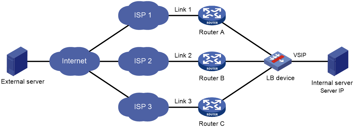
As shown in Figure 1, outbound link load balancing contains the following elements:
· LB device—Distributes outbound traffic among multiple links.
· Link—Physical links provided by ISPs.
· VSIP—Virtual service IP address of the cluster, which identifies the destination network for packets from the internal network.
· Server IP—IP address of a server.
Workflow
Figure 2 shows the outbound link load balancing workflow.
Figure 2 Outbound link load balancing workflow

The workflow for outbound link load balancing is as follows:
1. The LB device receives traffic from the internal server.
2. The LB device selects the optimal link based on the LB policy, sticky method, proximity algorithm, and scheduling algorithm (typically the bandwidth algorithm or maximum bandwidth algorithm) in turn.
3. The LB device forwards the traffic to the external server through the optimal link.
4. The LB device receives traffic from the external server.
5. The LB device forwards the traffic to the internal server.
Restrictions: Hardware compatibility with outbound link load balancing
|
Hardware series |
Model |
Product code |
Outbound link load balancing compatibility |
|
WX1800H series |
WX1804H-PWR |
EWP-WX1804H-PWR-CN |
Yes |
|
WX2500H series |
WX2508H-PWR-LTE WX2510H-PWR WX2510H-F-PWR WX2540H WX2540H-F WX2560H |
EWP-WX2508H-PWR-LTE EWP-WX2510H-PWR EWP-WX2510H-F-PWR EWP-WX2540H EWP-WX2540H-F EWP-WX2560H |
Yes |
|
MAK series |
MAK204 MAK206 |
EWP-MAK204 EWP-MAK206 |
Yes |
|
WX3000H series |
WX3010H WX3010H-X-PWR WX3010H-L-PWR WX3024H WX3024H-L-PWR WX3024H-F |
EWP-WX3010H EWP-WX3010H-X-PWR EWP-WX3010H-L-PWR EWP-WX3024H EWP-WX3024H-L-PWR EWP-WX3024H-F |
No |
|
WX3500H series |
WX3508H WX3508H WX3510H WX3510H WX3520H WX3520H-F WX3540H WX3540H |
EWP-WX3508H EWP-WX3508H-F EWP-WX3510H EWP-WX3510H-F EWP-WX3520H EWP-WX3520H-F EWP-WX3540H EWP-WX3540H-F |
No |
|
WX5500E series |
WX5510E WX5540E |
EWP-WX5510E EWP-WX5540E |
No |
|
WX5500H series |
WX5540H WX5560H WX5580H |
EWP-WX5540H EWP-WX5560H EWP-WX5580H |
No |
|
Access controller modules |
LSUM1WCME0 EWPXM1WCME0 LSQM1WCMX20 LSUM1WCMX20RT LSQM1WCMX40 LSUM1WCMX40RT EWPXM2WCMD0F EWPXM1MAC0F |
LSUM1WCME0 EWPXM1WCME0 LSQM1WCMX20 LSUM1WCMX20RT LSQM1WCMX40 LSUM1WCMX40RT EWPXM2WCMD0F EWPXM1MAC0F |
No |
|
Hardware series |
Model |
Product code |
Outbound link load balancing compatibility |
|
WX1800H series |
WX1804H-PWR WX1810H-PWR WX1820H WX1840H |
EWP-WX1804H-PWR EWP-WX1810H-PWR EWP-WX1820H EWP-WX1840H-GL |
Yes |
|
WX3800H series |
WX3820H WX3840H |
EWP-WX3820H-GL EWP-WX3840H-GL |
No |
|
WX5800H series |
WX5860H |
EWP-WX5860H-GL |
No |
Outbound link load balancing tasks at a glance
Relationship between configuration items
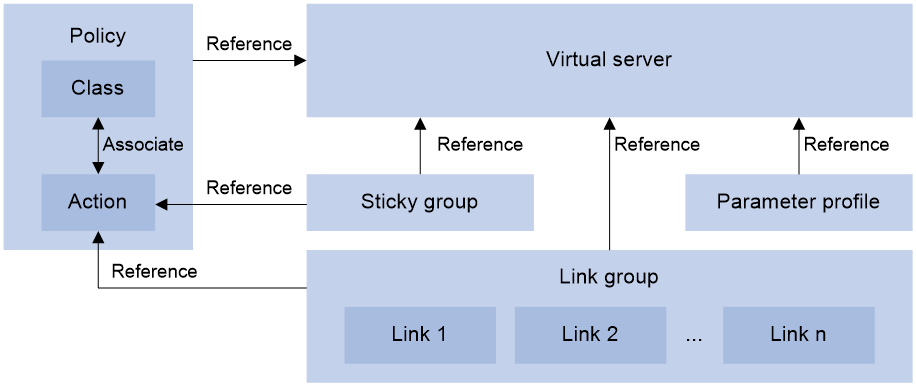
Figure 3 shows the relationship between the following configuration items:
· Link group—A collection of links that contain similar functions. A link group can be referenced by a virtual server or an LB action.
· Link—Physical links provided by ISPs.
· Virtual server—A virtual service provided by the LB device to determine whether to perform load balancing for packets received on the LB device. Only the packets that match a virtual server are load balanced.
· LB class—Classifies packets to implement load balancing based on packet type.
· LB action—Drops, forwards, or modifies packets.
· LB policy—Associates an LB class with an LB action. An LB policy can be referenced by a virtual server.
· Sticky group—Uses a sticky method to distribute similar sessions to the same link. A sticky group can be referenced by a virtual server or an LB action.
· Parameter profile—Defines advanced parameters to process packets. A parameter profile can be referenced by a virtual server.
Figure 3 Relationship between the main configuration items
Tasks at a glance
To configure outbound link load balancing, perform the following tasks:
3. Configuring a virtual server
4. (Optional.) Configuring an LB policy
5. (Optional.) Configuring a sticky group
6. (Optional.) Configuring a parameter profile
7. (Optional.) Configuring ISP information
8. (Optional.) Configuring the ALG feature
9. (Optional.) Performing a load balancing test
10. (Optional.) Configuring SNMP notifications and logging for load balancing
¡ Enabling load balancing logging
Configuring a link group
You can add links that contain similar functions to a link group to facilitate management.
Link group tasks at a glance
To configure a link group, perform the following tasks:
2. Configuring a scheduling algorithm for a link group
3. Setting the availability criteria
5. (Optional.) Configuring SNAT
6. (Optional.) Enabling the slow online feature
7. (Optional.) Configuring health monitoring
8. (Optional.) Specifying a fault processing method
9. (Optional.) Configuring the proximity feature
Creating a link group
1. Enter system view.
system-view
2. Create a link group and enter link group view.
loadbalance link-group link-group-name
3. (Optional.) Configure a description for the link group.
description text
By default, no description is configured for a link group.
Configuring a scheduling algorithm for a link group
About this task
Perform this task to specify a scheduling algorithm for a link group and specify the number of links to participate in scheduling. The LB device calculates the links to process user requests based on the specified scheduling algorithm.
The device provides the following scheduling algorithms for a link group:
· Weighted least connection algorithm (link-based)—Always assigns user requests to the link with the fewest number of weighted active connections (the total number of active connections in all link groups divided by weight). The weight value used in this algorithm is configured in real server view.
· Random algorithm—Randomly assigns user requests to links.
· Round robin algorithm—Assigns user requests to links based on the weights of links. A higher weight indicates more user requests will be assigned.
· Bandwidth algorithm—Distributes user requests to links according to the weights and remaining bandwidth of links.
· Maximum bandwidth algorithm—Distributes user requests always to an idle link that has the largest remaining bandwidth.
· Source IP address hash algorithm—Hashes the source IP address of user requests and distributes user requests to different links according to the hash values.
· Source IP address and port hash algorithm—Hashes the source IP address and port number of user requests and distributes user requests to different links according to the hash values.
· Destination IP address hash algorithm—Hashes the destination IP address of user requests and distributes user requests to different links according to the hash values.
Procedure
1. Enter system view.
system-view
2. Enter link group view.
loadbalance link-group link-group-name
3. Specify a scheduling algorithm for the link group.
predictor hash address { destination | source | source-ip-port } [ mask mask-length ] [ prefix prefix-length ]
predictor { least-connection | { bandwidth | max-bandwidth } [ inbound | outbound ] | random | round-robin }
By default, the scheduling algorithm for a link group is weighted round robin.
4. Specify the number of links to participate in scheduling.
selected-link min min-number max max-number
By default, the links with the highest priority participate in scheduling.
Setting the availability criteria
About this task
Perform this task to set the criteria (lower percentage and higher percentage) to determine whether a link group is available. This helps implement traffic switchover between the master and backup link groups.
· When the number of available links to the total number of links in the master link group is smaller than the lower percentage, traffic is switched to the backup link group.
· When the number of available links to the total number of links in the master link group is greater than the upper percentage, traffic is switched back to the master link group.
Procedure
1. Enter system view.
system-view
2. Enter link group view.
loadbalance link-group link-group-name
3. Set the criteria to determine whether the link group is available.
activate lower lower-percentage upper upper-percentage
By default, when a minimum of one link is available, the link group is available.
Disabling NAT
Restrictions and guidelines
Typically, outbound link load balancing networking requires disabling NAT for a link group.
Procedure
1. Enter system view.
system-view
2. Enter link group view.
loadbalance link-group link-group-name
3. Disable NAT for the link group.
transparent enable
By default, NAT is enabled for a link group.
Configuring SNAT
About this task
After a link group references the SNAT address pool, the LB device replaces the source address of the packets it receives with an SNAT address before forwarding the packets.
Restrictions and guidelines
An SNAT address pool can have a maximum of 256 IPv4 addresses and 65536 IPv6 addresses. No overlapping IPv4 or IPv6 addresses are allowed in different SNAT address pools.
As a best practice, do not use SNAT because its application scope is limited for outbound link load balancing.
Procedure
1. Enter system view.
system-view
2. Create an SNAT address pool and enter SNAT address pool view.
loadbalance snat-pool pool-name
3. (Optional.) Configure a description for the SNAT address pool.
description text
By default, no description is configured for an SNAT address pool.
4. Specify an address range for the SNAT address pool.
IPv4:
ip range start start-ipv4-address end end-ipv4-address
IPv6:
ipv6 range start start-ipv6-address end end-ipv6-address
By default, an SNAT address pool does not contain address ranges.
5. Return to system view.
quit
6. Enter link group view.
loadbalance link-group link-group-name
7. Specify the SNAT address pool to be referenced by the link group.
snat-pool pool-name
By default, no SNAT address pool is referenced by a link group.
Enabling the slow online feature
About this task
Links newly added to a link group might be unable to immediately process large numbers of services assigned by the LB device. To resolve this issue, enable the slow online feature for the link group. The feature uses the standby timer and ramp-up timer. When the links are brought online, the LB device does not assign any services to the links until the standby timer expires.
When the standby timer expires, the ramp-up timer starts. During the ramp-up time, the LB device increases the service amount according to the processing capability of the links, until the ramp-up timer expires.
Procedure
1. Enter system view.
system-view
2. Enter link group view.
loadbalance link-group link-group-name
3. Enable the slow online feature for the link group.
slow-online [ standby-time standby-time ramp-up-time ramp-up-time ]
By default, the slow online feature is disabled for a link group.
Configuring health monitoring
About this task
Perform this task to enable health monitoring to detect the availability of links.
Restrictions and guidelines
The health monitoring configuration in link view takes precedence over the configuration in link group view.
You can specify an NQA template or load balancing template for health monitoring. For information about NQA templates, see NQA configuration in Network Management and Monitoring Configuration Guide.
Procedure
1. Enter system view.
system-view
2. Enter link group view.
loadbalance link-group link-group-name
3. Specify a health monitoring method for the link group.
probe template-name
By default, no health monitoring method is specified for a link group.
4. Specify the health monitoring success criteria for the link group.
success-criteria { all | at-least min-number }
By default, health monitoring succeeds only when all the specified health monitoring methods succeed.
Specifying a fault processing method
About this task
Perform this task to specify one of the following fault processing methods for a link group:
· Keep—Does not actively terminate the connection with the failed link. Keeping or terminating the connection depends on the timeout mechanism of the protocol.
· Reschedule—Redirects the connection to another available link in the link group.
· Reset—Terminates the connection with the failed link by sending RST packets (for TCP packets) or ICMP unreachable packets (for other types of packets).
Procedure
1. Enter system view.
system-view
2. Enter link group view.
loadbalance link-group link-group-name
3. Specify a fault processing method for the link group.
fail-action { keep | reschedule | reset }
By default, the fault processing method is keep. All available connections are kept.
Configuring the proximity feature
About this task
The proximity feature performs link detection to select the optimal link to a destination. If no proximity information for a destination is available, the load balancing module selects a link based on the scheduling algorithm. It then performs proximity detection to generate proximity entries for forwarding subsequent traffic.
You can specify an NQA template or load-balancing probe template to perform link detection. The device generates proximity entries according to the detection results and proximity parameter settings. For information about NQA templates, see NQA configuration in Network Management and Monitoring Configuration Guide.
Restrictions and guidelines
To configure the proximity feature, first configure proximity parameters in proximity view, and then enable the proximity feature in link group view.
Configuring a load balancing probe template
1. Enter system view.
system-view
2. Create a load balancing probe template and enter load balancing probe template view.
loadbalance probe-template icmp template-name
3. Set the probe interval.
frequency interval
The default setting is 300 seconds.
4. Set the timeout time for probe responses.
timeout timeout-value
The default setting is 3 seconds.
Configuring proximity parameters
1. Enter system view.
system-view
2. Enter proximity view.
loadbalance proximity
3. Specify the proximity probe method for packets.
match [ match-id ] { tcp } { lb-probe lb-template | probe nqa-template }
By default, no proximity probe method is specified.
4. Specify the default proximity probe method.
match default { lb-probe lb-template | probe nqa-template }
By default, the default proximity probe method is not specified.
5. Set the mask length for IPv4 proximity entries.
ip mask { mask-length | mask }
By default, the mask length for IPv4 proximity entries is 24.
6. Set the prefix length for IPv6 proximity entries.
ipv6 prefix prefix-length
By default, the prefix length for IPv6 proximity entries is 96.
7. Set the network delay weight for proximity calculation.
rtt weight rtt-weight
By default, the network delay weight for proximity calculation is 100.
8. Set the TTL weight for proximity calculation.
ttl weight ttl-weight
By default, the TTL weight for proximity calculation is 100.
9. Set the bandwidth weight for proximity calculation.
bandwidth { inbound | outbound } weight bandwidth-weight
By default, the inbound or outbound bandwidth weight for proximity calculation is 100.
10. Set the cost weight for proximity calculation.
cost weight cost-weight
By default, the cost weight for proximity calculation is 100.
11. Set the aging timer for proximity entries.
timeout timeout-value
By default, the aging timer for proximity entries is 60 seconds.
12. Set the maximum number of proximity entries.
max-number number
By default, the number of proximity entries is not limited.
Enabling the proximity feature
1. Enter system view.
system-view
2. Enter link group view.
loadbalance link-group link-group-name
3. Enable the proximity feature.
proximity enable
By default, the proximity feature is disabled for a link group.
Configuring a link
A link is a physical link provided by an ISP. A link can belong to only one link group. A link group can have multiple links.
Link tasks at a glance
To configure a link, perform the following tasks:
1. Creating a link and specifying a link group
2. Specifying a next hop IP address or an outgoing interface
Choose one of the following tasks:
¡ Specifying an outbound next hop for a link
¡ Specifying an outgoing interface for a link
3. Setting a weight and priority
4. (Optional.) Configuring the bandwidth and connection parameters
5. (Optional.) Configuring health monitoring
6. (Optional.) Enabling the slow offline feature
7. (Optional.) Setting the link cost for proximity calculation
8. (Optional.) Setting the bandwidth ratio and maximum expected bandwidth
Creating a link and specifying a link group
1. Enter system view.
system-view
2. Create a link and enter link view.
loadbalance link link-name
By default, no links exist.
3. (Optional.) Configure a description for the link.
description text
By default, no description is configured for a link.
4. Specify a link group for the link.
link-group link-group-name
By default, a link does not belong to any link group.
Specifying an outbound next hop for a link
1. Enter system view.
system-view
2. Enter link view.
loadbalance link link-name
3. Specify an outbound next hop for the link.
IPv4:
router ip ipv4-address
IPv6:
router ipv6 ipv6-address
By default, a link does not have an outbound next hop.
Specifying an outgoing interface for a link
About this task
In scenarios where IP addresses are obtained through PPPoE, an LB device can dynamically obtain the outbound next hop IP address through the specified outgoing interface.
Procedure
1. Enter system view.
system-view
2. Enter link view.
loadbalance link link-name
3. Specify an outgoing interface for the link.
router interface interface-type interface-number
By default, no outgoing interface is specified for a link.
Setting a weight and priority
About this task
Perform this task to configure a weight for the weighted round robin and weighted least connection algorithms of a link, and the scheduling priority in the link group for the server.
Procedure
1. Enter system view.
system-view
2. Enter link view.
loadbalance link link-name
3. Set a weight for the link.
weight weight-value
By default, the weight of a link is 100.
4. Set a priority for the link.
priority priority
By default, the priority of a link is 4.
Configuring the bandwidth and connection parameters
1. Enter system view.
system-view
2. Enter link view.
loadbalance link link-name
3. Set the maximum bandwidth for the link.
rate-limit bandwidth [ inbound | outbound ] bandwidth-value
By default, the maximum bandwidth, inbound bandwidth, and outbound bandwidth are 0 KBps for a link. The bandwidths are not limited.
4. Set the maximum number of connections for the link.
connection-limit max max-number
By default, the maximum number of connections is 0 for a link. The number is not limited.
5. Set the maximum number of connections per second for the link.
rate-limit connection connection-number
By default, the maximum number of connections per second is 0 for a link. The number is not limited.
Configuring health monitoring
About this task
Perform this task to enable health monitoring to detect the availability of a link.
Restrictions and guidelines
The health monitoring configuration in link view takes precedence over the configuration in link group view.
Procedure
1. Enter system view.
system-view
2. Enter link view.
loadbalance link link-name
3. Specify a health monitoring method for the link.
probe template-name
By default, no health monitoring method is specified for a link.
4. Specify the health monitoring success criteria for the link.
success-criteria { all | at-least min-number }
By default, the health monitoring succeeds only when all the specified health monitoring methods succeed.
Enabling the slow offline feature
About this task
The shutdown command immediately terminates existing connections of a link. The slow offline feature ages out the connections, and does not establish new connections.
Restrictions and guidelines
To enable the slow offline feature for a link, you must execute the slow-shutdown enable command and then the shutdown command. If you execute the shutdown command and then the slow-shutdown enable command, the slow offline feature does not take effect and the link is shut down.
Procedure
1. Enter system view.
system-view
2. Enter link view.
loadbalance link link-name
3. Enable the slow offline feature for the link.
slow-shutdown enable
By default, the slow offline feature is disabled.
4. Shut down the link.
shutdown
By default, the link is activated.
Setting the link cost for proximity calculation
1. Enter system view.
system-view
2. Enter link view.
loadbalance link link-name
3. Set the link cost for proximity calculation.
cost cost-value
By default, the link cost for proximity calculation is 0.
Setting the bandwidth ratio and maximum expected bandwidth
About this task
When the traffic exceeds the maximum expected bandwidth multiplied by the bandwidth ratio of a link, new traffic (traffic that does not match any sticky entries) is not distributed to the link. When the traffic drops below the maximum expected bandwidth multiplied by the bandwidth recovery ratio of the link, the link participates in scheduling again.
In addition to being used for link protection, the maximum expected bandwidth is used for remaining bandwidth calculation in the bandwidth algorithm, maximum bandwidth algorithm, and dynamic proximity algorithm.
Procedure
1. Enter system view.
system-view
2. Enter link view.
loadbalance link link-name
3. Set the bandwidth ratio.
bandwidth [ inbound | outbound ] busy-rate busy-rate-number [ recovery recovery-rate-number ]
By default, the total bandwidth ratio is 70.
4. Set the maximum expected bandwidth.
max-bandwidth [ inbound | outbound ] bandwidth-value
By default, the maximum expected bandwidth, maximum uplink expected bandwidth, and maximum downlink expected bandwidth are 0 KBps. The bandwidths are not limited.
Configuring a virtual server
A virtual server is a virtual service provided by the LB device to determine whether to perform load balancing for packets received on the LB device. Only the packets that match a virtual server are load balanced.
Restrictions and guidelines
Outbound link load balancing supports only the link-IP virtual server.
Virtual server tasks at a glance
To configure a virtual server, perform the following tasks:
2. Specifying the VSIP and port number
3. Configuring a packet processing policy
Choose the following tasks as needed:
4. (Optional.) Specifying a parameter profile
5. (Optional.) Configuring the bandwidth and connection parameters
6. (Optional.) Enabling the link protection feature
7. (Optional.) Enabling bandwidth statistics collection by interfaces
Creating a virtual server
1. Enter system view.
system-view
2. Create a link-IP virtual server and enter virtual server view.
virtual-server virtual-server-name type link-ip
3. (Optional.) Configure a description for the virtual server.
description text
By default, no description is configured for the virtual server.
Specifying the VSIP and port number
1. Enter system view.
system-view
2. Enter link-IP virtual server view.
virtual-server virtual-server-name
3. Specify the VSIP for the virtual server.
IPv4:
virtual ip address ipv4-address [ mask-length | mask ]
IPv6:
virtual ipv6 address ipv6-address [ prefix-length ]
By default, no IPv4 or IPv6 address is specified for a virtual server.
4. Specify the port number for the virtual server.
port port-number
By default, the port number is 0 (meaning any port number) for a link-IP virtual server.
Specifying link groups
About this task
When the primary link group is available (contains available links), the virtual server forwards packets through the primary link group. When the primary link group is not available, the virtual server forwards packets through the backup link group.
Procedure
1. Enter system view.
system-view
2. Enter virtual server view.
virtual-server virtual-server-name
3. Specify link groups.
default link-group link-group-name [ backup backup-link-group-name ] [ sticky sticky-name ]
By default, no link group is specified for a virtual server.
Specifying an LB policy
About this task
By referencing an LB policy, the virtual server load balances matching packets based on the packet contents.
Procedure
1. Enter system view.
system-view
2. Enter virtual server view.
virtual-server virtual-server-name
3. Specify an LB policy for the virtual server.
lb-policy policy-name
By default, the virtual server does not reference any LB policies.
A virtual server can only reference a policy profile of the specified type. For example, a virtual server of the link-IP type can only reference a policy profile of the link-generic type.
Specifying a parameter profile
About this task
You can configure advanced parameters through a parameter profile. The virtual server references the parameter profile to analyze, process, and optimize service traffic.
Procedure
1. Enter system view.
system-view
2. Enter virtual server view.
virtual-server virtual-server-name
3. Specify a parameter profile for the virtual server.
parameter ip profile-name
By default, the virtual server does not reference any parameter profiles.
Configuring the bandwidth and connection parameters
1. Enter system view.
system-view
2. Enter virtual server view.
virtual-server virtual-server-name
3. Set the maximum bandwidth for the virtual server.
rate-limit bandwidth [ inbound | outbound ] bandwidth-value
By default, the maximum bandwidth, inbound bandwidth, and outbound bandwidth for the virtual server are 0 KBps. The bandwidths are not limited.
4. Set the maximum number of connections for the virtual server.
connection-limit max max-number
By default, the maximum number of connections of the virtual server is 0. The number is not limited.
5. Set the maximum number of connections per second for the virtual server.
rate-limit connection connection-number
By default, the maximum number of connections per second for the virtual server is 0. The number is not limited.
Enabling the link protection feature
About this task
Perform this task to prevent traffic from overwhelming a busy link. If traffic exceeds the bandwidth ratio of a link, the LB device distributes new traffic that does not match any sticky entries to other links.
Restrictions and guidelines
This feature takes effect only when bandwidth statistics collection by interfaces is enabled.
Procedure
1. Enter system view.
system-view
2. Enter virtual server view.
virtual-server virtual-server-name
3. Enable the link protection feature.
bandwidth busy-protection enable
By default, the link protection feature is disabled.
Enabling bandwidth statistics collection by interfaces
About this task
By default, the load balancing module automatically collects link bandwidth statistics. Perform this task to enable interfaces to collect bandwidth statistics.
Procedure
1. Enter system view.
system-view
2. Enter virtual server view.
virtual-server virtual-server-name
3. Enable bandwidth statistics collection by interfaces.
bandwidth interface statistics enable
By default, bandwidth statistics collection by interfaces is disabled.
Enabling a virtual server
About this task
After you configure a virtual server, you must enable the virtual server for it to work.
Procedure
1. Enter system view.
system-view
2. Enter virtual server view.
virtual-server virtual-server-name
3. Enable the virtual server.
service enable
By default, the virtual server is disabled.
Configuring an LB class
An LB class classifies packets by comparing packets against specific rules. Matching packets are further processed by LB actions. You can create a maximum of 65535 rules for an LB class.
LB class tasks at a glance
To configure an LB class, perform the following tasks:
2. Creating a match rule
Choose the following tasks as needed:
¡ Creating a match rule that references an LB class
¡ Creating a source IP address match rule
¡ Creating a destination IP address match rule
¡ Creating an input interface match rule
¡ Creating a user group match rule
¡ Creating a domain name match rule
¡ Creating an application group match rule
Creating an LB class
1. Enter system view.
system-view
2. Create a link-generic LB class, and enter LB class view.
loadbalance class class-name type link-generic [ match-all | match-any ]
When you create an LB class, you must specify the class type. You can enter an existing LB class view without specifying the class type. If you specify the class type when entering an existing LB class view, the class type must be the one specified when you create the LB class.
3. (Optional.) Configure a description for the LB class.
description text
By default, no description is configured for the LB class.
Creating a match rule that references an LB class
1. Enter system view.
system-view
2. Enter LB class view.
loadbalance class class-name
3. Create a match rule that references an LB class.
match [ match-id ] class class-name
Creating a source IP address match rule
1. Enter system view.
system-view
2. Enter LB class view.
loadbalance class class-name
3. Create a source IP address match rule.
match [ match-id ] source { ip address ipv4-address [ mask-length | mask ] | ipv6 address ipv6-address [ prefix-length ] }
Creating a destination IP address match rule
1. Enter system view.
system-view
2. Enter LB class view.
loadbalance class class-name
3. Create a destination IP address match rule.
match [ match-id ] destination { ip address ipv4-address [ mask-length | mask ] | ipv6 address ipv6-address [ prefix-length ] }
Creating an ACL match rule
1. Enter system view.
system-view
2. Enter LB class view.
loadbalance class class-name
3. Create an ACL match rule.
match [ match-id ] acl [ ipv6 ] { acl-number | name acl-name }
Creating an input interface match rule
1. Enter system view.
system-view
2. Enter LB class view.
loadbalance class class-name
3. Create an input interface match rule.
match [ match-id ] interface interface-type interface-number
Creating a user match rule
1. Enter system view.
system-view
2. Enter LB class view.
loadbalance class class-name
3. Create a user match rule.
match [ match-id ] [ identity-domain domain-name ] user user-name
Creating a user group match rule
1. Enter system view.
system-view
2. Enter LB class view.
loadbalance class class-name
3. Create a user group match rule.
match [ match-id ] [ identity-domain domain-name ] user-group user-group-name
Creating a domain name match rule
About this task
The LB device stores mappings between domain names and IP addresses in the DNS cache. If the destination IP address of an incoming packet matches an IP address in the DNS cache, the LB device queries the domain name for the IP address. If the queried domain name matches the domain name configured in a match rule, the LB device takes the LB action on the packet.
Procedure
1. Enter system view.
system-view
2. Enter LB class view.
loadbalance class class-name
3. Create a domain name match rule.
match [ match-id ] destination domain-name domain-name
By default, an LB class does not have any match rules.
Creating an ISP match rule
1. Enter system view.
system-view
2. Enter LB class view.
loadbalance class class-name
3. Create an ISP match rule.
match [ match-id ] isp isp-name
Creating an application group match rule
1. Enter system view.
system-view
2. Enter LB class view.
loadbalance class class-name
3. Create an application group match rule.
match [ match-id ] app-group group-name
Configuring an LB action
About LB actions
LB actions include the following modes:
· Forwarding mode—Determines whether and how to forward packets. If no forwarding action is specified, packets are dropped.
· Modification mode—Modifies packets. To prevent the LB device from dropping the modified packets, the modification action must be used together with a forwarding action.
If you create an LB action without specifying any of the previous action modes, packets are dropped.
Restrictions and guidelines
The "Configuring the forwarding mode" and "Specifying link groups" tasks are mutually exclusive. Configuring one task automatically cancels the other task that you have configured.
LB action tasks at a glance
To configure an LB action, perform the following tasks:
2. (Optional.) Configuring a forwarding LB action
¡ Configuring the forwarding mode
¡ (Optional.) Matching the next rule upon failure to find a link
3. (Optional.) Configuring a modification LB action
¡ Configuring the ToS field in IP packets sent to the server
Creating an LB action
1. Enter system view.
system-view
2. Create a link-generic LB action and enter LB action view.
loadbalance action action-name type link-generic
When you create an LB action, you must specify the action type. You can enter an existing LB action view without specifying the action type. If you specify the action type when entering an existing LB action view, the action type must be the one specified when you create the LB action.
3. (Optional.) Configure a description for the LB action.
description text
By default, no description is configured for the LB action.
Configuring a forwarding LB action
About this task
Three forwarding LB action types are available:
· Forward—Forwards matching packets.
· Specify link groups—When the primary link group is available (contains available real servers), the primary link group is used to guide packet forwarding. When the primary link group is not available, the backup link group is used to guide packet forwarding.
· Match the next rule upon failure to find a link—If the device fails to find a link according to the LB action, it matches the packet with the next rule in the LB policy.
Configuring the forwarding mode
1. Enter system view.
system-view
2. Enter LB action view.
loadbalance action action-name
3. Configure the forwarding mode.
forward all
By default, the forwarding mode is to discard packets.
Specifying link groups
1. Enter system view.
system-view
2. Enter LB action view.
loadbalance action action-name
3. Specify link groups.
link-group link-group-name [ backup backup-link-group-name ] [ sticky sticky-name ]
By default, no link group is specified.
Matching the next rule upon failure to find a link
1. Enter system view.
system-view
2. Enter LB action view.
loadbalance action action-name
3. Match the next rule upon failure to find a link.
fallback-action continue
By default, the next rule is not matched when no links are available for the current LB action.
Configuring the ToS field in IP packets sent to the server
1. Enter system view.
system-view
2. Enter LB action view.
loadbalance action action-name
3. Configure the ToS field in IP packets sent to the server.
set ip tos tos-number
By default, the ToS field in IP packets sent to the server is not changed.
Configuring an LB policy
About LB policies
An LB policy associates an LB class with an LB action to guide packet forwarding. In an LB policy, you can configure an LB action for packets matching the specified LB class, and configure the default action for packets matching no LB class.
You can specify multiple LB classes for an LB policy. Packets match the LB classes in the order the LB classes are configured. If an LB class is matched, the specified LB action is performed. If no LB class is matched, the default LB action is performed.
LB policy tasks at a glance
To configure an LB policy, perform the following tasks:
3. Specifying the default LB action
Creating an LB policy
1. Enter system view.
system-view
2. Create a link-generic LB policy, and enter LB action view.
loadbalance policy policy-name type link-generic
When you create an LB policy, you must specify the policy type. You can enter an existing LB policy view without specifying the policy type. If you specify the policy type when entering an existing LB policy view, the policy type must be the one specified when you create the LB policy.
3. (Optional.) Configure a description for the LB policy.
description text
By default, no description is configured for an LB policy.
Specifying an LB action
Restrictions and guidelines
A link-generic LB policy can reference only link-generic LB classes and link-generic LB actions.
Procedure
1. Enter system view.
system-view
2. Enter LB policy view.
loadbalance policy policy-name
3. Specify an LB action for the specified LB class.
class class-name [ insert-before before-class-name ] action action-name
By default, no LB action is specified for any LB classes.
You can specify an LB action for different LB classes.
Specifying the default LB action
Restrictions and guidelines
A link-generic LB policy can only reference link-generic LB actions.
Procedure
1. Enter system view.
system-view
2. Enter LB policy view.
loadbalance policy policy-name
3. Specify the default LB action.
default-class action action-name
By default, no default LB action is specified.
Configuring a sticky group
A sticky group uses a sticky method to distribute similar sessions to the same link according to sticky entries. The sticky method applies to the first packet of a session. Other packets of the session are distributed to the same link.
Sticky group tasks at a glance
To configure a sticky group, perform the following tasks:
2. Configuring the IP sticky method
3. (Optional.) Configuring the timeout time for sticky entries
4. (Optional.) Ignoring the limits for sessions that match sticky entries
Creating a sticky group
1. Enter system view.
system-view
2. Create an address- and port-type sticky group and enter sticky group view.
sticky-group group-name type address-port
When you create a sticky group, you must specify the group type. You can enter an existing sticky group view without specifying the group type. If you specify the group type when entering an existing sticky group view, the group type must be the one specified when you create the sticky group.
3. (Optional.) Configure a description for the sticky group.
description text
By default, no description is configured for the sticky group.
Configuring the IP sticky method
1. Enter system view.
system-view
2. Enter sticky group view.
sticky-group group-name
3. Configure the IP sticky method.
IPv4:
ip [ port ] { both | destination | source } [ mask mask-length ]
IPv6:
ipv6 [ port ] { both | destination | source } [ prefix prefix-length ]
By default, no IP sticky method is configured.
Configuring the timeout time for sticky entries
1. Enter system view.
system-view
2. Enter sticky group view.
sticky-group group-name
3. Configure the timeout time for sticky entries.
timeout timeout-value
By default, the timeout time for sticky entries is 86400 seconds for sticky groups of the HTTP cookie type and 60 seconds for sticky groups of other types.
Ignoring the limits for sessions that match sticky entries
About this task
Perform this task to ignore the following limits for sessions that match sticky entries:
· Bandwidth and connection parameters on links.
· LB connection limit policies on virtual servers.
Procedure
1. Enter system view.
system-view
2. Enter sticky group view.
sticky-group group-name
3. Ignore the limits for sessions that match sticky entries.
override-limit enable
By default, the session limits apply to sessions that match sticky entries.
Configuring a parameter profile
About configuring a parameter profile
You can configure advanced parameters through a parameter profile. The virtual server references the parameter profile to analyze, process, and optimize service traffic.
Creating a parameter profile
1. Enter system view.
system-view
2. Create an IP-type parameter profile and enter parameter profile view.
parameter-profile profile-name type ip
By default, no parameter profiles exist.
When you create a parameter profile, you must specify the profile type. You can enter an existing parameter profile view without specifying the profile type. If you specify the profile type when entering an existing parameter profile view, the profile type must be the one specified when you create the parameter profile.
3. (Optional.) Configure a description for the parameter profile.
description text
By default, no description is configured for the parameter profile.
Configuring the ToS field in IP packets sent to the client
1. Enter system view.
system-view
2. Enter IP parameter profile view.
parameter-profile profile-name
3. Configure the ToS field in IP packets sent to the client.
set ip tos tos-number
By default, the ToS field in IP packets sent to the client is not changed.
Configuring ISP information
About configuring ISP information
Perform this task to configure IP address information for an ISP. The IP address information can be used by an ISP match rule. When the destination IP address of packets matches the ISP match rule of an LB class, the LB device takes the action associated with the class. The device supports the following methods to configure IP address information:
· Manual configuration—The administrator manually specifies IP address information.
· ISP file import—The administrator manually imports an ISP file in .tp format.
Restrictions and guidelines
You can configure ISP information manually, import an ISP file, or use both methods.
Configuring ISP information manually
1. Enter system view.
system-view
2. Create an ISP and enter ISP view.
loadbalance isp name isp-name
3. Specify the IP address for the ISP.
IPv4:
ip address ipv4-address { mask-length | mask }
IPv6:
ipv6 address ipv6-address prefix-length
By default, an ISP does not contain IPv4 or IPv6 addresses.
An ISP does not allow overlapping network segments.
4. (Optional.) Configure a description for the ISP.
description text
By default, no description is configured for the ISP.
Importing an ISP file
1. Enter system view.
system-view
2. Import an ISP file.
loadbalance isp file isp-file-name
Configuring the ALG feature
About this task
The Application Level Gateway (ALG) feature distributes parent and child sessions to the same link.
Procedure
1. Enter system view.
system-view
2. Enable ALG.
¡ Enable
ALG for the specified protocol:
loadbalance
alg { dns | ftp | h323 | icmp-error | ils | mgcp | nbt | pptp | rsh | rtsp | sccp | sip | sqlnet | tftp | xdmcp }
¡ Enable ALG for all protocols:
loadbalance
alg all-enable
By default, ALG is enabled for the DNS, FTP, PPTP, and RTSP protocols and ICMP error packets.
Performing a load balancing test
About this task
Perform this task in any view to test the load balancing result.
Procedure
1. Execute the following command to perform an IPv4 load balancing test in any view:
loadbalance schedule-test ip { application http { message-file file-name | method { get | post } url url [ header header ]&<1-10> [ content content-value ] } | protocol { protocol-number | icmp | tcp | udp } } destination destination-address destination-port destination-port source source-address source-port source-port
2. Execute the following command to perform an IPv6 load balancing test in any view:
loadbalance schedule-test ipv6 { application http { message-file file-name | method { get | post } url url [ header header ]&<1-10> [ content content-value ] } | protocol { protocol-number | icmpv6 | tcp | udp } } destination destination-address destination-port destination-port source source-address source-port source-port
Enabling SNMP notifications
About this task
To report critical load balancing events to an NMS, enable SNMP notifications for load balancing. For load balancing event notifications to be sent correctly, you must also configure SNMP as described in Network Management and Monitoring Configuration Guide.
The SNMP notifications configuration tasks for Layer 4 and Layer 7 server load balancing are the same.
Procedure
1. Enter system view.
system-view
2. Enable SNMP notifications for load balancing.
snmp-agent trap enable loadbalance
By default, SNMP notifications are enabled for load balancing.
Enabling load balancing logging
About load balancing logging
For security auditing purposes, enable load balancing logging to record load balancing information. Load balancing logging includes the following types:
· Basic logging.
· NAT logging.
· Link busy state logging.
Basic logging generates logs for the following events:
· The state of a link or link group changes.
· The health monitoring result of a link changes.
· The number of connections on a link or virtual server reaches or drops below the upper limit.
· The connection establishment rate on a link or virtual server reaches or drops below the upper limit.
· A primary/backup server farm switchover occurs between server farms specified for a virtual server.
· A primary/backup server farm switchover occurs between server farms specified for an LB action.
NAT logging records NAT session information, including IP address and port translation information and access information.
Link busy state logging records busy states for all links.
Enabling load balancing basic logging
1. Enter system view.
system-view
2. Enable load balancing basic logging.
loadbalance log enable base
By default, load balancing basic logging is enabled.
Enabling load balancing NAT logging
1. Enter system view.
system-view
2. Enable load balancing NAT logging.
loadbalance log enable nat
By default, load balancing NAT logging is disabled.
Enabling load balancing link busy state logging
1. Enter system view.
system-view
2. Enable load balancing link busy state logging.
loadbalance log enable bandwidth-busy
By default, load balancing link busy state logging is disabled.
Displaying and maintaining outbound link load balancing
Execute display commands in any view and reset commands in user view.
|
Task |
Command |
|
Display LB action information. |
display loadbalance action [ name action-name ] |
|
Display LB class information. |
display loadbalance class [ name class-name ] |
|
Display ISP information. |
display loadbalance isp [ ip ipv4-address | ipv6 ipv6-address | name isp-name ] |
|
Display LB policy information. |
display loadbalance policy [ name policy-name ] |
|
Display proximity entry information. |
display loadbalance proximity [ ip [ ipv4-address ] | ipv6 [ ipv6-address ] ] |
|
Display parameter profile information. |
display parameter-profile [ name parameter-name ] |
|
Display link information. |
display loadbalance link [ brief | name link-name ] |
|
Display link statistics. |
display loadbalance link statistics [ name link-name ] |
|
Display link outbound interface statistics. |
display loadbalance link out-interface statistics [ name link-name ] |
|
Display link group information. |
display loadbalance link-group [ brief | name link-group-name ] |
|
Display sticky entry information. |
display sticky virtual-server [ virtual-server-name ] [ class class-name | default-class | default-link-group ] |
|
Display sticky group information. |
display sticky-group [ name group-name ] |
|
Display virtual server information. |
display virtual-server [ brief | name virtual-server-name ] |
|
Display virtual server statistics. |
display virtual-server statistics [ name virtual-server-name ] |
|
Display the ALG status for all protocols. |
|
|
Clear proximity entry information. |
reset loadbalance proximity [ ip [ ipv4-address ] | ipv6 [ ipv6-address ] ] |
|
Clear all Layer 7 connections. |
reset loadbalance connections |
|
Clear link statistics. |
reset loadbalance link statistics [ link-name ] |
|
Clear virtual server statistics. |
reset virtual-server statistics [ virtual-server-name ] |
Outbound link load balancing configuration examples
Example: Configuring outbound link load balancing
Network configuration
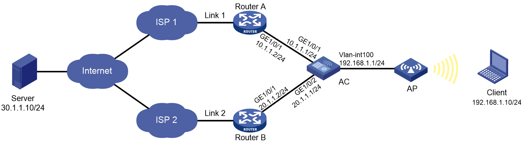
In Figure 4, ISP 1 and ISP 2 provide two links, Link 1 and Link 2, with the same router hop count, bandwidth, and cost. Link 1 has lower network delay.
Configure link load balancing for the AC to select an optimal link for traffic from the client to the server.
Procedure
1. Configure IP addresses for interfaces.
[AC] interface gigabitethernet 1/0/1
[AC-GigabitEthernet1/0/1] ip address 10.1.1.1 24
[AC-GigabitEthernet1/0/1] quit
[AC] interface gigabitethernet 1/0/2
[AC-GigabitEthernet1/0/2] ip address 20.1.1.1 24
[AC-GigabitEthernet1/0/2] quit
2. Configure a link group:
# Create the ICMP-type NQA template t1, and configure the NQA client to send the probe result to the feature that uses the template on a per-probe basis.
[AC-nqatplt-icmp-t1] reaction trigger per-probe
[AC-nqatplt-icmp-t1] quit
# Specify the default proximity probe method as t1, and set the network delay weight for proximity calculation to 200.
[AC-lb-proximity] match default probe t1
[AC-lb-proximity] rtt weight 200
[AC-lb-proximity] quit
# Create the link group lg, and enable the proximity feature.
[AC] loadbalance link-group lg
[AC-lb-lgroup-lg] proximity enable
# Disable the NAT feature.
[AC-lb-lgroup-lg] transparent enable
[AC-lb-lgroup-lg] quit
3. Configure links:
# Create the link link1 with next hop address 10.1.1.2, and add it to the link group lg.
[AC-lb-link-link1] router ip 10.1.1.2
[AC-lb-link-link1] link-group lg
[AC-lb-link-link1] quit
# Create the link link2 with next hop address 20.1.1.2, and add it to link group lg.
[AC-lb-link-link2] router ip 20.1.1.2
[AC-lb-link-link2] link-group lg
[AC-lb-link-link2] quit
4. Create the link-IP virtual server vs with VSIP 0.0.0.0/0, specify its default master link group lg, and enable the virtual server.
[AC] virtual-server vs type link-ip
[AC-vs-link-ip-vs] virtual ip address 0.0.0.0 0
[AC-vs-link-ip-vs] default link-group lg
[AC-vs-link-ip-vs] service enable
[AC-vs-link-ip-vs] quit
Verifying the configuration
# Display brief information about all links.
[AC] display loadbalance link brief
Link Route IP State VPN instance Link group
link1 10.1.1.2 Active lg
link2 20.1.1.2 Active lg
# Display detailed information about all link groups.
[AC] display loadbalance link-group
Link group: lg
Description:
Predictor: Round robin
Proximity: Enabled
NAT: Disabled
SNAT pool:
Failed action: Keep
Active threshold: Disabled
Slow-online: Disabled
Selected link: Disabled
Probe information:
Probe success criteria: All
Probe method:
t1
Total link: 2
Active link: 2
Link list:
Name State VPN instance Router IP Weight Priority
link1 Active 10.1.1.2 100 4
link2 Active 20.1.1.2 100 4
# Display detailed information about all virtual servers.
Virtual server: vs
Description:
Type: LINK-IP
State: Active
VPN instance:
Virtual IPv4 address: 0.0.0.0/0
Virtual IPv6 address: --
Port: 0
Primary link group: lg (in use)
Backup link group:
Sticky:
LB policy:
LB limit-policy:
Connection limit: --
Rate limit:
Connections: --
Bandwidth: --
Inbound bandwidth: --
Outbound bandwidth: --
Connection synchronization: Disabled
Sticky synchronization: Disabled
Bandwidth busy protection: Disabled
Interface bandwidth statistics: Disabled
Route advertisement: Disabled
# Display brief information about all IPv4 proximity entries.
[AC] display loadbalance proximity ip
IPv4 entries in total: 1
IPv4 address/Mask length Timeout Best link
------------------------------------------------------------
10.1.1.0/24 50 link1
Configuring transparent DNS proxies
About transparent DNS proxies
Application scenario
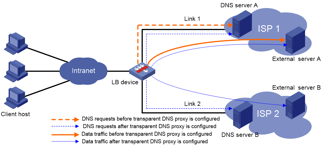
As shown in Figure 5, intranet users of an enterprise can access external servers A and B through link 1 of ISP 1 and link 2 of ISP 2. External servers A and B provide the same services. All DNS requests of intranet users are forwarded to DNS server A, which returns the resolved IP address of external server A to the requesting users. In this way, all traffic of intranet users is forwarded on one link. Link congestion might occur.
The transparent DNS proxy feature can solve this problem by forwarding DNS requests to DNS servers in different ISPs. All traffic from intranet users is evenly distributed on multiple links. This feature can prevent link congestion and ensure service continuity upon a link failure.
Figure 5 Transparent DNS proxy working mechanism
Workflow
The transparent DNS proxy is implemented by changing the destination IP address of DNS requests.
Figure 6 Transparent DNS proxy workflow
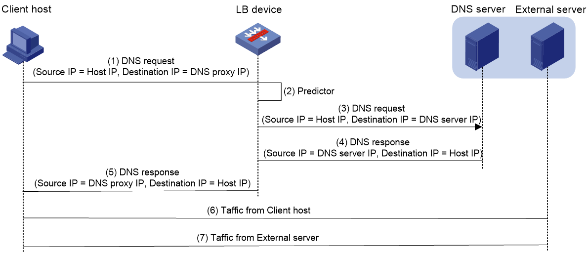
Table 1 Workflow description
|
Step |
Source IP address |
Destination IP address |
|
1. An intranet user on the client host sends a DNS request to the LB device. |
Host IP address |
IP address of DNS server A |
|
2. The LB device selects a DNS server to forward the DNS request according to the scheduling algorithm. |
N/A |
N/A |
|
3. The LB device changes the destination IP address of the DNS request as the IP address of the selected DNS server. |
Host IP address |
IP address of the selected DNS server |
|
4. The DNS server processes the DNS request and replies with a DNS response. |
IP address of the selected DNS server |
Host IP address |
|
5. The LB device changes the source IP address of the DNS response as the destination IP address of the DNS request. |
IP address of DNS server A |
Host IP address |
|
6. The intranet user accesses the external server according to the resolved IP address in the DNS response. |
Host IP address |
IP address of the external server |
|
7. The external server responds to the intranet user. |
IP address of the external server |
Host IP address |
Transparent DNS proxy on the LB device
The LB device distributes DNS requests to multiple links by changing the destination IP address of DNS requests.
As shown in Figure 7, the LB device contains the following elements:
· Transparent DNS proxy—The LB device performs transparent DNS proxy for a DNS request only when the port number of the DNS request matches the port number of the transparent DNS proxy.
· DNS server pool—A group of DNS servers.
· DNS server—Entity that processes DNS requests.
· Link—Physical link provided by an ISP.
· LB class—Classifies packets to implement load balancing based on packet type.
· LB action—Drops, forwards, or modifies packets.
· LB policy—Associates an LB class with an LB action. An LB policy can be referenced by the transparent DNS proxy.
Figure 7 Transparent DNS proxy on the LB device
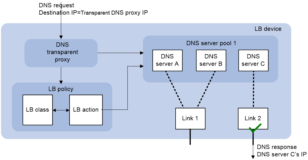
If the destination IP address and port number of a DNS request match those of the transparent DNS proxy, the LB device processes the DNS request as follows:
1. The LB device finds the DNS server pool associated with the transparent DNS proxy.
2. The LB device selects a DNS server according to the scheduling algorithm configured for the DNS server pool.
3. The LB device uses the IP address of the selected DNS server as the destination IP address of the DNS request, and sends the request to the DNS server.
4. The DNS server receives and processes the DNS request, and replies with a DNS response.
The intranet user can now access the external server after receiving the DNS response.
Restrictions: Hardware compatibility with transparent DNS proxies
|
Hardware series |
Model |
Product code |
Transparent DNS proxy compatibility |
|
WX1800H series |
WX1804H-PWR |
EWP-WX1804H-PWR-CN |
Yes |
|
WX2500H series |
WX2508H-PWR-LTE WX2510H-PWR WX2510H-F-PWR WX2540H WX2540H-F WX2560H |
EWP-WX2508H-PWR-LTE EWP-WX2510H-PWR EWP-WX2510H-F-PWR EWP-WX2540H EWP-WX2540H-F EWP-WX2560H |
Yes |
|
MAK series |
MAK204 MAK206 |
EWP-MAK204 EWP-MAK206 |
Yes |
|
WX3000H series |
WX3010H WX3010H-X-PWR WX3010H-L-PWR WX3024H WX3024H-L-PWR WX3024H-F |
EWP-WX3010H EWP-WX3010H-X-PWR EWP-WX3010H-L-PWR EWP-WX3024H EWP-WX3024H-L-PWR EWP-WX3024H-F |
No |
|
WX3500H series |
WX3508H WX3508H WX3510H WX3510H WX3520H WX3520H-F WX3540H WX3540H |
EWP-WX3508H EWP-WX3508H-F EWP-WX3510H EWP-WX3510H-F EWP-WX3520H EWP-WX3520H-F EWP-WX3540H EWP-WX3540H-F |
No |
|
WX5500E series |
WX5510E WX5540E |
EWP-WX5510E EWP-WX5540E |
No |
|
WX5500H series |
WX5540H WX5560H WX5580H |
EWP-WX5540H EWP-WX5560H EWP-WX5580H |
No |
|
Access controller modules |
LSUM1WCME0 EWPXM1WCME0 LSQM1WCMX20 LSUM1WCMX20RT LSQM1WCMX40 LSUM1WCMX40RT EWPXM2WCMD0F EWPXM1MAC0F |
LSUM1WCME0 EWPXM1WCME0 LSQM1WCMX20 LSUM1WCMX20RT LSQM1WCMX40 LSUM1WCMX40RT EWPXM2WCMD0F EWPXM1MAC0F |
No |
|
Hardware series |
Model |
Product code |
Transparent DNS proxy compatibility |
|
WX1800H series |
WX1804H-PWR WX1810H-PWR WX1820H WX1840H |
EWP-WX1804H-PWR EWP-WX1810H-PWR EWP-WX1820H EWP-WX1840H-GL |
Yes |
|
WX3800H series |
WX3820H WX3840H |
EWP-WX3820H-GL EWP-WX3840H-GL |
No |
|
WX5800H series |
WX5860H |
EWP-WX5860H-GL |
No |
Transparent DNS proxy tasks at a glance
To configure the transparent DNS proxy feature, perform the following tasks:
1. Configuring a transparent DNS proxy
2. Configuring a DNS server pool
5. (Optional.) Configuring an LB policy
6. (Optional.) Configuring a sticky group
7. (Optional.) Enabling load balancing logging
Configuring a transparent DNS proxy
By configuring a transparent DNS proxy, you can load balance DNS requests that match the transparent DNS proxy.
Restrictions and guidelines
If both the "Specifying the default DNS server pool" and "Specifying an LB policy" tasks are configured, packets are processed by the LB policy first. If the processing fails, the packets are processed by the default DNS server pool.
Transparent DNS proxy tasks at a glance
To configure a transparent DNS proxy, perform the following tasks:
1. Creating a transparent DNS proxy
2. Specifying an IP address and port number
3. Configuring a packet processing policy
Choose the following tasks as needed:
¡ Specifying the default DNS server pool
4. (Optional.) Enabling the link protection feature
5. Enabling the transparent DNS proxy
Creating a transparent DNS proxy
1. Enter system view.
system-view
2. Create a transparent DNS proxy and enter its view.
loadbalance dns-proxy dns-proxy-name type udp
Specifying an IP address and port number
Restrictions and guidelines
As a best practice, configure an all-zero IP address for a transparent DNS proxy. In this case, all DNS requests are processed by the transparent DNS proxy.
Procedure
1. Enter system view.
system-view
2. Enter transparent DNS proxy view.
loadbalance dns-proxy dns-proxy-name
3. Specify an IP address for the transparent DNS proxy.
IPv4:
ip address ipv4-address [ mask-length | mask ]
IPv6:
ipv6 address ipv6-address [ prefix-length ]
By default, no IP address is specified for a transparent DNS proxy.
4. Specify the port number for the transparent DNS proxy.
port port-number
By default, the port number is 53 for a transparent DNS proxy.
Specifying the default DNS server pool
1. Enter system view.
system-view
2. Enter transparent DNS proxy view.
loadbalance dns-proxy dns-proxy-name
3. Specify the default DNS server pool for the transparent DNS proxy.
default dns-server-pool pool-name [ sticky sticky-name ]
By default, no default DNS server pool is specified for a transparent DNS proxy.
Specifying an LB policy
About this task
By referencing an LB policy, the transparent DNS proxy load balances matching DNS requests based on the packet contents. For more information about configuring an LB policy, see "Configuring an LB policy."
Procedure
1. Enter system view.
system-view
2. Enter transparent DNS proxy view.
loadbalance dns-proxy dns-proxy-name
3. Specify an LB policy for the transparent DNS proxy.
lb-policy policy-name
By default, a transparent DNS proxy does not reference any LB policies.
Enabling the link protection feature
About this task
This feature enables a transparent DNS proxy to select a DNS server based on the link bandwidth ratio. If the bandwidth ratio of a link is exceeded, the DNS server is not selected.
If the traffic volume on the link to a DNS server exceeds the maximum expected bandwidth multiplied by the bandwidth ratio, the DNS server is busy and will not be selected. If the traffic volume drops below the maximum expected bandwidth multiplied by the bandwidth recovery ratio, the DNS server participates in scheduling again. For more information about setting the bandwidth ratio, see "Setting the bandwidth ratio and maximum expected bandwidth."
Procedure
1. Enter system view.
system-view
2. Enter transparent DNS proxy view.
loadbalance dns-proxy dns-proxy-name
3. Enable the link protection feature.
bandwidth busy-protection enable
By default, the link protection feature is disabled.
Enabling the transparent DNS proxy
About this task
After configuring a transparent DNS proxy, you must enable the transparent DNS proxy for it to work.
Procedure
1. Enter system view.
system-view
2. Enter transparent DNS proxy view.
loadbalance dns-proxy dns-proxy-name
3. Enable the transparent DNS proxy.
service enable
By default, a transparent DNS proxy is disabled.
Configuring a DNS server pool
By configuring a DNS server pool, you can perform centralized management on DNS servers that have similar functions.
Creating a DNS server pool
1. Enter system view.
system-view
2. Create a DNS server pool and enter its view.
loadbalance dns-server-pool pool-name
3. (Optional.) Configure a description for the DNS server pool.
description text
By default, no description is configured for a DNS server pool.
Configuring a scheduling algorithm for a DNS server pool
About this task
Perform this task to specify a scheduling algorithm for a DNS server pool and specify the number of DNS servers to participate in scheduling. The LB device calculates the DNS servers to process DNS requests based on the following scheduling algorithms:
· Source IP address hash algorithm—Hashes the source IP address of DNS requests and distributes DNS requests to different DNS servers according to the hash values. This hash algorithm ensures that DNS requests with the same source IP address are distributed to the same DNS server.
· Source IP address and port hash algorithm—Hashes the source IP address and port number of DNS requests and distributes DNS requests to different DNS servers according to the hash values. This hash algorithm ensures that DNS requests with the same source IP address and port number are distributed to the same DNS server.
· Destination IP address hash algorithm—Hashes the destination IP address of DNS requests and distributes DNS requests to different DNS servers according to the hash values. This hash algorithm ensures that DNS requests with the same destination IP address are distributed to the same DNS server.
· Random algorithm—Distributes DNS requests to DNS servers randomly.
· Weighted round-robin algorithm—Distributes DNS requests to DNS servers in a round-robin manner according to the weights of DNS servers. For example, you can assign weight values 2 and 1 to DNS server A and DNS server B, respectively. This algorithm distributes two DNS requests to DNS server A and then distributes one DNS request to DNS server B. This algorithm applies to scenarios where DNS servers have different performance and bear similar load for each session.
· Bandwidth algorithm—Distributes DNS requests to DNS servers according to the weights and remaining bandwidths of DNS servers. When the remaining bandwidths of two DNS servers are the same, this algorithm is equivalent to the round-robin algorithm. When the weights of two DNS servers are the same, this algorithm always distributes DNS requests to the DNS server that has larger remaining bandwidth.
· Maximum bandwidth algorithm—Distributes DNS requests always to an idle DNS server that has the largest remaining bandwidth.
Procedure
1. Enter system view.
system-view
2. Enter DNS server pool view.
loadbalance dns-server-pool pool-name
3. Specify a scheduling algorithm for the DNS server pool.
predictor hash address { destination | source | source-ip-port } [ mask mask-length ] [ prefix prefix-length ]
predictor { random | round-robin | { bandwidth | max-bandwidth } [ inbound | outbound ] }
By default, the scheduling algorithm for a DNS server pool is weighted round robin.
4. Specify the number of DNS servers to participate in scheduling.
selected-server min min-number max max-number
By default, the DNS servers with the highest priority participate in scheduling.
Configuring health monitoring
About this task
Perform this task to enable health monitoring to detect the availability of DNS servers in a DNS server pool.
Restrictions and guidelines
The health monitoring configuration in DNS server view takes precedence over the configuration in DNS server pool view.
You can specify an NQA template or load balancing template for health monitoring. For information about NQA templates, see NQA configuration in Network Management and Monitoring Configuration Guide.
Procedure
1. Enter system view.
system-view
2. Enter DNS server pool view.
loadbalance dns-server-pool pool-name
3. Specify a health monitoring method for the DNS server pool.
probe template-name
By default, no health monitoring method is specified for a DNS server pool.
4. Specify the health monitoring success criteria for the DNS server pool.
success-criteria { all | at-least min-number }
By default, health monitoring succeeds only when all the specified health monitoring methods succeed.
Configuring a DNS server
Perform this task to configure an entity on the LB device for processing DNS requests. DNS servers configured on the LB device correspond to DNS servers in ISP networks. A DNS server can belong to only one DNS server pool. A DNS server pool can contain multiple DNS servers.
DNS server tasks at a glance
To configure a DNS server, perform the following tasks:
1. Creating a DNS server and specifying a DNS server pool
2. Configuring an IP address for a DNS server
Choose one of the following tasks:
¡ Specifying an IP address and port number
¡ Enabling the device to automatically obtain the IP address of a DNS server
3. Associating a link with a DNS server
4. (Optional.) Setting a weight and priority
5. (Optional.) Configuring health monitoring
Creating a DNS server and specifying a DNS server pool
1. Enter system view.
system-view
2. Create a DNS server and enter its view.
loadbalance dns-server dns-server-name
3. (Optional.) Configure a description for the DNS server.
description text
By default, no description is configured for a DNS server.
4. Specify a DNS server pool for the DNS server.
dns-server-pool pool-name
By default, a DNS server does not belong to any DNS server pool.
Specifying an IP address and port number
1. Enter system view.
system-view
2. Enter DNS server view.
loadbalance dns-server dns-server-name
3. Specify an IP address for the DNS server.
IPv4:
ip address ipv4-address
IPv6:
ipv6 address ipv6-address
By default, no IP address is specified for a DNS server.
4. Specify the port number for the DNS server.
port port-number
By default, the port number of a DNS server is 0. Packets use their own port numbers.
Enabling the device to automatically obtain the IP address of a DNS server
About this task
In scenarios where IP addresses are obtained through PPPoE, an LB device can dynamically obtain the IP address of a DNS server.
Before configuring this task, you must specify the outgoing interface for the link associated with the DNS server. Otherwise, the IP address of the DNS server cannot be obtained.
Procedure
1. Enter system view.
system-view
2. Enter DNS server view.
loadbalance dns-server dns-server-name
3. Enable the device to automatically obtain the IP address of the DNS server.
auto-alloc address
By default, the device does not automatically obtain the IP address of a DNS server.
Associating a link with a DNS server
Restrictions and guidelines
A DNS server can be associated with only one link. A link can be associated with multiple DNS servers.
Procedure
1. Enter system view.
system-view
2. Enter DNS server view.
loadbalance dns-server dns-server-name
3. Associate a link with the DNS server.
link link-name
By default, no link is associated with a DNS server.
Setting a weight and priority
About this task
Perform this task to set a weight for the weighted round robin algorithm and bandwidth algorithm of a DNS server, and set the scheduling priority in the DNS server pool for the DNS server.
Procedure
1. Enter system view.
system-view
2. Enter DNS server view.
loadbalance dns-server dns-server-name
3. Set a weight for the DNS server.
weight weight-value
By default, the weight of a DNS server is 100.
4. Set a priority for the DNS server.
priority priority
By default, the priority of a DNS server is 4.
Configuring health monitoring
About this task
Perform this task to enable health monitoring to detect the availability of a DNS server.
Restrictions and guidelines
The health monitoring configuration in DNS server view takes precedence over the configuration in DNS server pool view.
Procedure
1. Enter system view.
system-view
2. Enter DNS server view.
loadbalance dns-server dns-server-name
3. Specify a health monitoring method for the DNS server.
probe template-name
By default, no health monitoring method is specified for a DNS server.
4. Specify the health monitoring success criteria for the DNS server.
success-criteria { all | at-least min-number }
By default, health monitoring succeeds only when all the specified health monitoring methods succeed.
Configuring a link
A link is a physical link provided by an ISP. You can guide traffic forwarding by specifying an outbound next hop for a link. You can enhance link performance by configuring the maximum bandwidth, health monitoring, bandwidth ratio, and maximum expected bandwidth.
Link tasks at a glance
To configure a link, perform the following tasks:
2. Specifying a next hop IP address or an outgoing interface
Choose one of the following tasks:
¡ Specifying an outbound next hop for a link
¡ Specifying an outgoing interface for a link
3. (Optional.) Configuring the maximum bandwidth
4. (Optional.) Configuring health monitoring
5. (Optional.) Setting the bandwidth ratio and maximum expected bandwidth
Creating a link
1. Enter system view.
system-view
2. Create a link and enter link view.
loadbalance link link-name
3. (Optional.) Configure a description for the link.
description text
By default, no description is configured for a link.
Specifying an outbound next hop for a link
1. Enter system view.
system-view
2. Enter link view.
loadbalance link link-name
3. Specify an outbound next hop for the link.
IPv4:
router ip ipv4-address
IPv6:
router ipv6 ipv6-address
By default, no outbound next hop is specified for a link.
Specifying an outgoing interface for a link
About this task
In scenarios where IP addresses are obtained through PPPoE, an LB device can dynamically obtain the outbound next hop IP address through the specified outgoing interface.
Procedure
1. Enter system view.
system-view
2. Enter link view.
loadbalance link link-name
3. Specify an outgoing interface for the link.
router interface interface-type interface-number
By default, no outgoing interface is specified for a link.
Configuring the maximum bandwidth
1. Enter system view.
system-view
2. Enter link view.
loadbalance link link-name
3. Set the maximum bandwidth for the link.
rate-limit bandwidth [ inbound | outbound ] bandwidth-value
By default, the maximum bandwidth for a link is not limited.
Configuring health monitoring
About this task
Perform this task to enable health monitoring to detect the availability of a link.
Procedure
1. Enter system view.
system-view
2. Enter link view.
loadbalance link link-name
3. Specify a health monitoring method for the link.
probe template-name
By default, no health monitoring method is specified for a link.
4. Specify the health monitoring success criteria for the link.
success-criteria { all | at-least min-number }
By default, the health monitoring succeeds only when all the specified health monitoring methods succeed.
Setting the bandwidth ratio and maximum expected bandwidth
About this task
When the traffic exceeds the maximum expected bandwidth multiplied by the bandwidth ratio of a link, new traffic (traffic that does not match any sticky entries) is not distributed to the link. When the traffic drops below the maximum expected bandwidth multiplied by the bandwidth recovery ratio of the link, the link participates in scheduling again.
In addition to being used for link protection, the maximum expected bandwidth is used for remaining bandwidth calculation in the bandwidth algorithm and maximum bandwidth algorithm.
Procedure
1. Enter system view.
system-view
2. Enter link view.
loadbalance link link-name
3. Set the bandwidth ratio.
bandwidth [ inbound | outbound ] busy-rate busy-rate-number [ recovery recovery-rate-number ]
By default, the total bandwidth ratio is 70.
4. Set the maximum expected bandwidth.
max-bandwidth [ inbound | outbound ] bandwidth-value
By default, the maximum expected bandwidth is not limited.
Configuring an LB class
An LB class classifies packets by comparing packets against specific rules. Matching packets are further processed by LB actions. You can create a maximum of 65535 rules for an LB class.
LB class tasks at a glance
To configure an LB class, perform the following tasks:
2. Creating a match rule
Choose the following tasks as needed:
¡ Creating a match rule that references an LB class
¡ Creating a source IP address match rule
¡ Creating a destination IP address match rule
¡ Creating a domain name match rule
Creating an LB class
1. Enter system view.
system-view
2. Create a DNS LB class, and enter LB class view.
loadbalance class class-name type dns [ match-all | match-any ]
When you create an LB class, you must specify the class type. You can enter an existing LB class view without specifying the class type. If you specify the class type when entering an existing LB class view, the class type must be the one specified when you create the LB class.
3. (Optional.) Configure a description for the LB class.
description text
By default, no description is configured for an LB class.
Creating a match rule that references an LB class
1. Enter system view.
system-view
2. Enter LB class view.
loadbalance class class-name
3. Create a match rule that references an LB class.
match [ match-id ] class class-name
Creating a source IP address match rule
1. Enter system view.
system-view
2. Enter LB class view.
loadbalance class class-name
3. Create a source IP address match rule.
match [ match-id ] source { ip address ipv4-address [ mask-length | mask ] | ipv6 address ipv6-address [ prefix-length ] }
Creating a destination IP address match rule
1. Enter system view.
system-view
2. Enter LB class view.
loadbalance class class-name
3. Create a destination IP address match rule.
match [ match-id ] destination { ip address ipv4-address [ mask-length | mask ] | ipv6 address ipv6-address [ prefix-length ] }
Creating an ACL match rule
Restrictions and guidelines
If the specified ACL does not exist, the ACL match rule does not take effect.
Procedure
1. Enter system view.
system-view
2. Enter LB class view.
loadbalance class class-name
3. Create an ACL match rule.
match [ match-id ] acl [ ipv6 ] { acl-number | name acl-name }
By default, an LB class does not have any match rules.
Creating a domain name match rule
1. Enter system view.
system-view
2. Enter LB class view.
loadbalance class class-name
3. Create a domain name match rule.
match [ match-id ] domain-name domain-name
Configuring an LB action
About LB actions
LB actions include the following modes:
· Forwarding mode—Determines whether and how to forward packets. If no forwarding action is specified, packets are dropped.
· Modification mode—Modifies packets. To prevent the LB device from dropping the modified packets, the modification action must be used together with a forwarding action.
If you create an LB action without specifying any of the previous action modes, packets are dropped.
Restrictions and guidelines
The following tasks are mutually exclusive:
· Configuring the forwarding mode
· Specifying a DNS server pool for guiding packet forwarding
· Skipping the current transparent DNS proxy
Configuring one task automatically cancels the other task that you have configured.
LB action tasks at a glance
To configure an LB action, perform the following tasks:
2. (Optional.) Configuring a forwarding LB action
¡ Configuring the forwarding mode
¡ Specifying a DNS server pool for guiding packet forwarding
¡ Skipping the current transparent DNS proxy
¡ Matching the next rule upon failure to find a DNS server
3. (Optional.) Configuring a modification LB action
¡ Configuring the ToS field in IP packets sent to the DNS server
Creating an LB action
1. Enter system view.
system-view
2. Create a DNS LB action and enter LB action view.
loadbalance action action-name type dns
When you create an LB action, you must specify the action type. You can enter an existing LB action view without specifying the action type. If you specify the action type when entering an existing LB action view, the action type must be the one specified when you create the LB action.
3. (Optional.) Configure a description for the LB action.
description text
By default, no description is configured for an LB action.
Configuring a forwarding LB action
About this task
Three forwarding LB action types are available:
· Forward—Forwards matching packets.
· Specify a DNS server pool for guiding packet forwarding.
· Skip the current transparent DNS proxy—Skips the current transparent DNS proxy and match the next transparent DNS proxy or virtual server.
· Match the next rule upon failure to find a DNS server—If the device fails to find a DNS server according to the LB action, it matches the packet with the next rule in the LB policy.
Configuring the forwarding mode
1. Enter system view.
system-view
2. Enter DNS LB action view.
loadbalance action action-name
3. Configure the forwarding mode.
forward all
By default, the forwarding mode is to discard packets.
Specifying a DNS server pool for guiding packet forwarding
1. Enter system view.
system-view
2. Enter DNS LB action view.
loadbalance action action-name
3. Specify a DNS server pool for guiding packet forwarding.
dns-server-pool pool-name [ sticky sticky-name ]
By default, no DNS server pool is specified for guiding packet forwarding.
Skipping the current transparent DNS proxy
1. Enter system view.
system-view
2. Enter DNS LB action view.
loadbalance action action-name
3. Skip the current transparent DNS proxy.
skip current-dns-proxy
By default, the forwarding mode is to discard packets.
Matching the next rule upon failure to find a DNS server
1. Enter system view.
system-view
2. Enter DNS LB action view.
loadbalance action action-name
3. Match the next rule upon failure to find a DNS server.
fallback-action continue
By default, the next rule is not matched (packets are dropped) when no DNS servers are available for an LB action.
Configuring the ToS field in IP packets sent to the DNS server
1. Enter system view.
system-view
2. Enter DNS LB action view.
loadbalance action action-name
3. Configure the ToS field in IP packets sent to the DNS server.
set ip tos tos-number
By default, the ToS field in IP packets sent to the DNS server is not changed.
Configuring an LB policy
LB policy tasks at a glance
To configure an LB policy, perform the following tasks:
3. Specifying the default LB action
Creating an LB policy
1. Enter system view.
system-view
2. Create a DNS LB policy and enter LB action view.
loadbalance policy policy-name type dns
When you create an LB policy, you must specify the policy type. You can enter an existing LB policy view without specifying the policy type. If you specify the policy type when entering an existing LB policy view, the policy type must be the one specified when you create the LB policy.
3. (Optional.) Configure a description for the LB policy.
description text
By default, no description is configured for an LB policy.
Specifying an LB action
Restrictions and guidelines
A DNS LB policy can reference only DNS LB classes and DNS LB actions.
Procedure
1. Enter system view.
system-view
2. Enter DNS LB policy view.
loadbalance policy policy-name
3. Specify an LB action for an LB class.
class class-name [ insert-before before-class-name ] action action-name
By default, no LB action is specified for an LB class.
Specifying the default LB action
Restrictions and guidelines
The default LB action takes effect on packets that do not match any LB classes.
A DNS LB policy can reference only a DNS LB action as the default LB action.
Procedure
1. Enter system view.
system-view
2. Enter DNS LB policy view.
loadbalance policy policy-name
3. Specify the default LB action.
default-class action action-name
By default, no default LB action is specified.
Configuring a sticky group
A sticky group uses a sticky method to distribute similar sessions to the same DNS server according to sticky entries. The sticky method applies to the first packet of a session. Other packets of the session are distributed to the same DNS server.
Sticky group tasks at a glance
To configure a sticky group, perform the following tasks:
2. Configuring the IP sticky method
3. (Optional.) Configuring the timeout time for sticky entries
Creating a sticky group
1. Enter system view.
system-view
2. Create an address- and port-type sticky group and enter sticky group view.
sticky-group group-name type address-port
When you create a sticky group, you must specify the group type. You can enter an existing sticky group view without specifying the group type. If you specify the group type when entering an existing sticky group view, the group type must be the one specified when you create the sticky group.
3. (Optional.) Configure a description for the sticky group.
description text
By default, no description is configured for a sticky group.
Configuring the IP sticky method
1. Enter system view.
system-view
2. Enter sticky group view.
sticky-group group-name
3. Configure the IP sticky method.
IPv4:
ip [ port ] { both | destination | source } [ mask mask-length ]
IPv6:
ipv6 [ port ] { both | destination | source } [ prefix prefix-length ]
By default, no IP sticky method is configured.
Configuring the timeout time for sticky entries
1. Enter system view.
system-view
2. Enter sticky group view.
sticky-group group-name
3. Configure the timeout time for sticky entries.
timeout timeout-value
By default, the timeout time for sticky entries is 60 seconds.
Enabling load balancing logging
About load balancing logging
For security auditing purposes, enable load balancing logging to record load balancing information. Load balancing logging includes NAT logging and link busy state logging.
NAT logging records NAT session information, including IP address and port translation information and access information.
Link busy state logging records busy states for all links.
Enabling load balancing NAT logging
1. Enter system view.
system-view
2. Enable load balancing NAT logging.
loadbalance log enable nat
By default, load balancing NAT logging is disabled.
Enabling load balancing link busy state logging
1. Enter system view.
system-view
2. Enable load balancing link busy state logging.
loadbalance log enable bandwidth-busy
By default, load balancing link busy state logging is disabled.
Displaying and maintaining transparent DNS proxy
Execute display commands in any view and reset commands in user view.
|
Task |
Command |
|
Display DNS server pool information. |
display loadbalance dns-server-pool [ brief | name pool-name ] |
|
Display DNS server information. |
display loadbalance dns-server [ brief | name dns-server-name ] |
|
Display DNS server statistics. |
display loadbalance dns-server statistics [ name dns-server-name ] |
|
Display transparent DNS proxy information. |
display loadbalance dns-proxy [ brief | name dns-proxy-name ] |
|
Display transparent DNS proxy statistics. |
display loadbalance dns-proxy statistics [ name dns-proxy-name ] |
|
Display link information. |
display loadbalance link [ brief | name link-name ] |
|
Display link statistics. |
display loadbalance link statistics [ name link-name ] |
|
Display LB class information. |
display loadbalance class [ name class-name ] |
|
Display LB action information. |
display loadbalance action [ name action-name ] |
|
Display LB policy information. |
display loadbalance policy [ name policy-name ] |
|
Display sticky entry information for transparent DNS proxies. |
display sticky dns-proxy [ dns-proxy-name ] [ class class-name | default-class | default-dns-server-pool ] |
|
Display sticky group information. |
display sticky-group [ name group-name ] |
|
Clear DNS server statistics. |
reset loadbalance dns-server statistics [ dns-server-name ] |
|
Clear transparent DNS proxy statistics. |
reset loadbalance dns-proxy statistics [ dns-proxy-name ] |
|
Clear link statistics. |
reset loadbalance link statistics [ link-name ] |
Transparent DNS proxy configuration examples
Example: Configuring transparent DNS proxy
Network configuration
In Figure 8, ISP 1 and ISP 2 provide two links with the same bandwidth: Link 1 and Link 2. The IP address of the DNS server of ISP 1 is 10.1.2.100. The IP address of the DNS server of ISP 2 is 20.1.2.100. Intranet users use domain name www.abc.com to access Web server A and Web server B.
Configure a transparent DNS proxy on the AC to evenly distribute user traffic to Link 1 and Link 2.
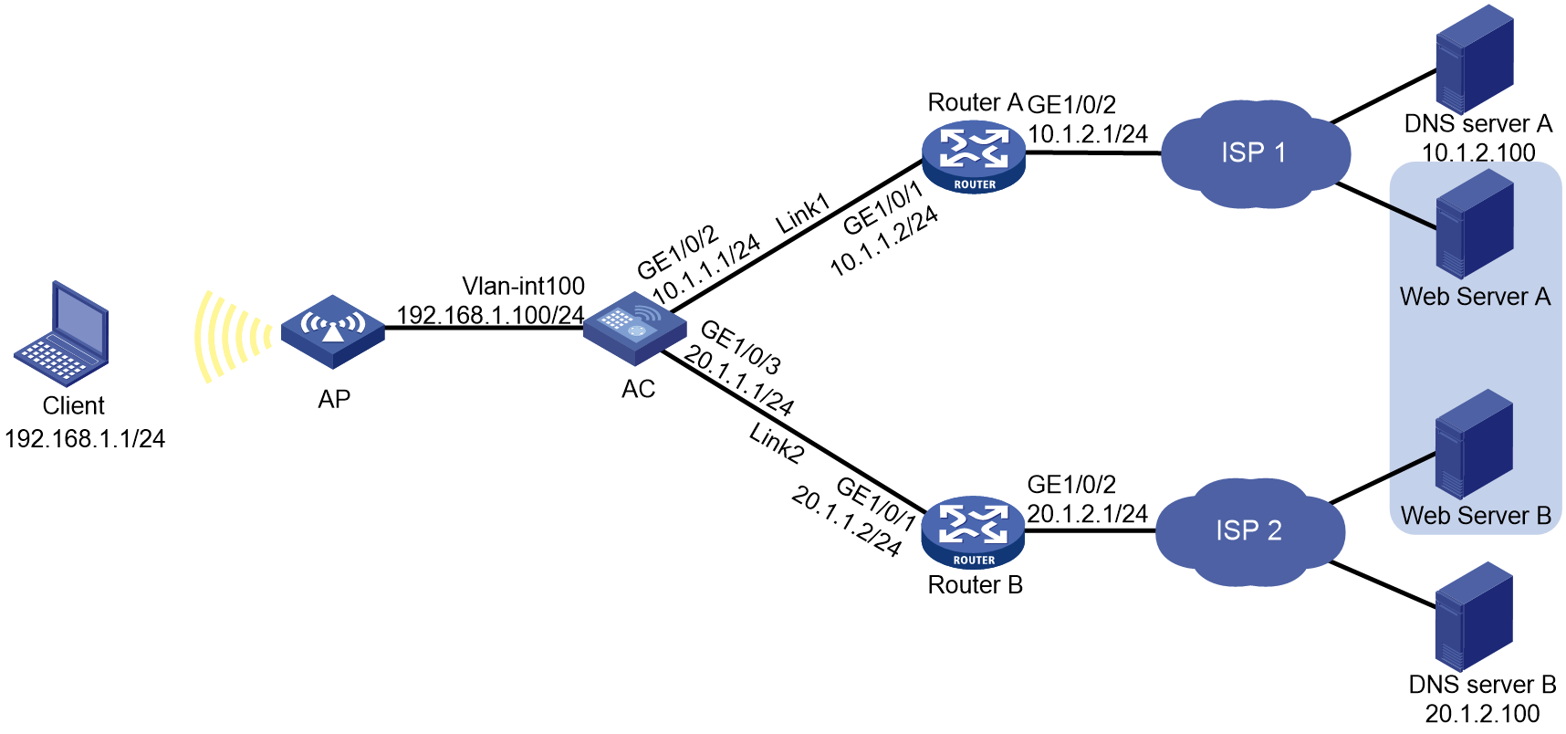
Procedure
1. Configure IP addresses for interfaces.
<AC> system-view
[AC] interface vlan-interface 100
[AC-Vlan-interface100] ip address 192.168.1.100 24
[AC-Vlan-interface100] quit
[AC] interface gigabitethernet 1/0/2
[AC-GigabitEthernet1/0/2] ip address 10.1.1.1 24
[AC-GigabitEthernet1/0/2] quit
[AC] interface gigabitethernet 1/0/3
[AC-GigabitEthernet1/0/3] ip address 20.1.1.1 24
[AC-GigabitEthernet1/0/3] quit
2. Configure links:
# Create the link link1 with next hop address 10.1.1.2.
[AC] loadbalance link link1
[AC-lb-link-link1] router ip 10.1.1.2
[AC-lb-link-link1] quit
# Create the link link2 with next hop address 20.1.1.2.
[AC] loadbalance link link2
[AC-lb-link-link2] router ip 20.1.1.2
[AC-lb-link-link2] quit
3. Create a DNS server pool named dsp.
[AC] loadbalance dns-server-pool dsp
[AC-lb-dspool-dsp] quit
4. Configure DNS servers:
# Create a DNS server named ds1, configure its IP address as 10.1.2.100, assign it to DNS server pool dsp, and associate it with link link1.
[AC] loadbalance dns-server ds1
[AC-lb-ds-ds1] ip address 10.1.2.100
[AC-lb-ds-ds1] dns-server-pool dsp
[AC-lb-ds-ds1] link link1
[AC-lb-ds-ds1] quit
# Create a DNS server named ds2, configure its IP address as 20.1.2.100, assign it to DNS server pool dsp, and associate it with link link2.
[AC] loadbalance dns-server ds2
[AC-lb-ds-ds2] ip address 20.1.2.100
[AC-lb-ds-ds2] dns-server-pool dsp
[AC-lb-ds-ds2] link link2
[AC-lb-ds-ds2] quit
5. Configure a transparent DNS proxy:
# Create a UDP transparent DNS proxy named dns-proxy1, configure its IP address as 0.0.0.0, specify DNS server pool dsp as its default DNS server pool, and enable the transparent DNS proxy.
[AC] loadbalance dns-proxy dns-proxy1 type udp
[AC-lb-dp-udp-dp] ip address 0.0.0.0 0
[AC-lb-dp-udp-dp] default dns-server-pool dsp
[AC-lb-dp-udp-dp] service enable
[AC-lb-dp-udp-dp] quit
Verifying the configuration
# Display brief information about all DNS servers.
[AC] display loadbalance dns-server brief
DNS server Address Port Link State DNS server pool
ds1 10.1.2.100 0 link1 Active dsp
ds2 20.1.2.100 0 link2 Active dsp
# Display detailed information about all DNS server pools.
[AC] display loadbalance dns-server-pool
DNS server pool: dsp
Description:
Predictor: Round robin
Selected server: Disabled
Probe information:
Probe success criteria: All
Probe method:
Total DNS servers: 2
Active DNS servers: 2
DNS server list:
Name State Address port Link Weight Priority
ds1 Active 10.1.2.100 0 link1 100 4
ds2 Active 20.1.2.100 0 link2 100 4
# Display detailed information about all transparent DNS proxies.
[AC] display loadbalance dns-proxy
DNS proxy: dns-proxy1
Type: UDP
State: Active
Service state: Enabled
VPN instance:
IPv4 address: 1.1.1.0/24
IPv6 address: --
Port: 53
DNS server pool: dsp
Sticky:
LB policy:
Connection synchronization: Enabled
Sticky synchronization: Enabled
Bandwidth busy protection: Disabled
After you complete the previous configuration, the LB device can evenly distribute DNS requests to DNS server A and DNS server B. Then, intranet user traffic is evenly distributed to Link 1 and Link 2.