- Table of Contents
- Related Documents
-
| Title | Size | Download |
|---|---|---|
| 03-Track configuration | 192.93 KB |
Contents
Restrictions and guidelines: Track configuration
Collaboration application example
Associating Track with a detection module object
Associating Track with interface management
Associating Track with route management
Associating Track with a tracked list
Associating Track with a Boolean list
Associating Track with a percentage threshold list
Associating Track with a weight threshold list
Associating the Track module with an application module
Prerequisites for associating the Track module with an application module
Associating Track with static routing
Associating Track with interface backup
Associating Track with WLAN uplink detection
Display and maintenance commands for Track
Example: Configuring static routing-Track-NQA collaboration
Configuring Track
About Track
Collaboration mechanism
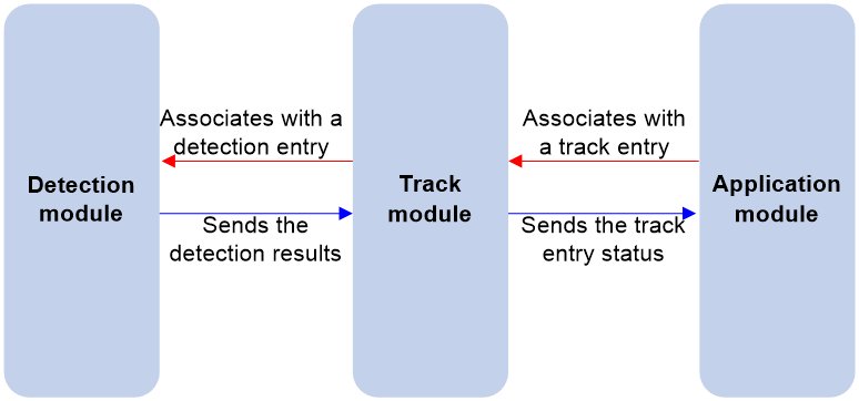
The Track module collaborates with detection modules and application modules.
As shown in Figure 1, collaboration is enabled when you associate the Track module with a detection module and an application module, and it operates as follows:
1. The detection module probes specific objects such as interface status, link status, network reachability, and network performance, and informs the Track module of detection results.
2. The Track module sends the detection results to the application module.
3. When notified of changes for the tracked object, the application modules can react to avoid communication interruption and network performance degradation.
Figure 1 Collaboration through the Track module
Collaboration between the Track module and a detection module
The detection module sends the detection result of the tracked object to the Track module. The Track module changes the status of the track entry as follows:
· If the tracked object operates correctly, the state of the track entry is Positive. For example, the track entry state is Positive in one of the following conditions:
¡ The target interface is up.
¡ The target network is reachable.
· If the tracked object does not operate correctly, the state of the track entry is Negative. For example, the track entry state is Negative in one of the following conditions:
¡ The target interface is down.
¡ The target network is unreachable.
· If the detection result is invalid, the state of the track entry is NotReady. For example, the track entry state is NotReady if its associated NQA operation does not exist.
Collaboration between the Track module and an application module
Supported detection modules
The following detection modules can be associated with the Track module:
· NQA.
· Interface management.
· Route management.
You can associate a track entry with an object of a detection module, such as the state of an interface or reachability of an IP route. The state of the track entry is determined by the state of the tracked object.
You can also associate a track entry with a list of objects called a tracked list. The state of a tracked list is determined by the states of all objects in the list. The following types of tracked lists are supported:
· Boolean AND list—The state of a Boolean AND list is determined by the states of the tracked objects using the Boolean AND operation.
· Boolean OR list—The state of a Boolean OR list is determined by the states of the tracked objects using the Boolean OR operation.
· Percentage threshold list—The state of a percentage threshold list is determined by comparing the percentage of Positive and Negative objects in the list with the percentage thresholds configured for the list.
· Weight threshold list—The state of a weight threshold list is determined by comparing the weight of Positive and Negative objects in the list with the weight thresholds configured for the list.
Supported application modules
The following application modules can be associated with the Track module:
· Static routing.
· PBR.
· Interface backup.
· WLAN uplink detection.
· EAA.
Restrictions and guidelines: Track configuration
When configuring a track entry for an application module, you can set a notification delay to avoid immediate notification of status changes.
When the delay is not configured and the route convergence is slower than the link state change notification, communication failures occur.
Collaboration application example
This example shows how to implement collaboration between NQA, Track, and uplink detection.
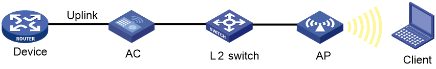
If the uplink fails, the AC disables the radio on the AP that associates with the AC. If the uplink recovers, the AC enables the radio on the AP. For this purpose, configure collaboration between the NQA, Track, and uplink detection.
1. Configure an NQA operation to check the accessibility of the Device.
2. Create a track entry and associate it with the NQA operation.
¡ When the Device is reachable, the track entry is in Positive state.
¡ When the Device becomes unreachable, the track entry is in Negative state.
3. Associate the track entry with the WLAN uplink detection feature.
¡ When the associated track entry turns to Negative state, the uplink detection feature disables the radio on the AP. Wireless clients will not be associated with the AP.
¡ When the track entry changes to the Positive state, the uplink detection feature enables the radio on the AP. Wireless clients can be associated with the AP.
Track tasks at a glance
To implement the collaboration function, establish associations between the Track module and detection modules, and between the Track module and application modules.
To configure the Track module, perform the following tasks:
1. Associating Track with a detection module object
¡ Associating Track with interface management
¡ Associating Track with route management
2. Associating Track with a tracked list
¡ Associating Track with a Boolean list
¡ Associating Track with a percentage threshold list
¡ Associating Track with a weight threshold list
3. Associating the Track module with an application module
¡ Associating Track with static routing
¡ Associating Track with interface backup
¡ Associating Track with WLAN uplink detection
Associating Track with a detection module object
Associating Track with NQA
About this task
NQA supports multiple operation types to analyze network performance and service quality. For example, an NQA operation can periodically detect whether a destination is reachable, or whether a TCP connection can be established.
An NQA operation operates as follows when it is associated with a track entry:
· If the consecutive probe failures reach the specified threshold, the NQA module notifies the Track module that the tracked object has malfunctioned. The Track module then sets the track entry to Negative state.
· If the specified threshold is not reached, the NQA module notifies the Track module that the tracked object is operating correctly. The Track module then sets the track entry to Positive state.
For more information about NQA, see Network Management and Monitoring Configuration Guide.
Restrictions and guidelines
If you associate a track entry with a nonexistent NQA operation or reaction entry, the state of the track entry is NotReady.
Procedure
1. Enter system view.
system-view
2. Create a track entry, associate it with an NQA reaction entry, and enter its view.
track track-entry-number nqa entry admin-name operation-tag reaction item-number
3. Set the delay for notifying the application module of track entry state changes.
delay { negative negative-time | positive positive-time } *
By default, the Track module notifies the application module immediately when the track entry state changes.
Associating Track with interface management
About this task
The interface management module monitors the link status, physical status, or network-layer protocol status of interfaces. The associated Track and interface management operate as follows:
· When the link status, physical status, or network-layer protocol status of the interface changes to up, the interface management module informs the Track module of the change. The Track module sets the track entry to Positive state.
· When the link status, physical status, or network-layer protocol status of the interface changes to down, the interface management module informs the Track module of the change. The Track module sets the track entry to Negative state.
Procedure
1. Enter system view.
system-view
2. Create a track entry, associate it with an interface, and enter its view.
¡ Create a track entry to monitor the link status of an interface.
track track-entry-number interface interface-type interface-number
¡ Create a track entry to monitor the physical status of an interface.
track track-entry-number interface interface-type interface-number physical
¡ Create a track entry to monitor the network layer protocol status of an interface.
track track-entry-number interface interface-type interface-number protocol { ipv4 | ipv6 }
3. Set the delay for notifying the application module of track entry state changes.
delay { negative negative-time | positive positive-time } *
By default, the Track module notifies the application module immediately when the track entry state changes.
Associating Track with route management
About this task
The route management module monitors route entry changes in the routing table. The associated Track and route management operate as follows:
· When a monitored route entry is found in the routing table, the route management module informs the Track module. The Track module sets the track entry to Positive state.
· When a monitored route entry is removed from the routing table, the route management module informs the Track module of the change. The Track module sets the track entry to Negative state.
Procedure
1. Enter system view.
system-view
2. Create a track entry, associate it with an IP route, and enter its view.
track track-entry-number ip route ip-address { mask-length | mask } reachability
3. Set the delay for notifying the application module of track entry state changes.
delay { negative negative-time | positive positive-time } *
By default, the Track module notifies the application module immediately when the track entry state changes.
Associating Track with a tracked list
Associating Track with a Boolean list
About this task
A Boolean list is a list of tracked objects based on a Boolean logic. It can be further divided into the following types:
· Boolean AND list—A Boolean AND list is set to the Positive state only when all objects are in Positive state. If one or more objects are in Negative state, the tracked list is set to the Negative state.
· Boolean OR list—A Boolean OR list is set to the Positive state if any object is in Positive state. If all objects are in Negative state, the tracked list is set to the Negative state.
Procedure
1. Enter system view.
system-view
2. Create a track entry.
See "Associating Track with a detection module object."
Create a track entry before you add it as a tracked object to a tracked list.
A minimum of one track entry must be created.
3. Create a Boolean tracked list and enter its view.
track track-entry-number list boolean { and | or }
4. Add the track entry as an object to the tracked list.
object track-entry-number [ not ]
Repeat this step to add all interested objects to the tracked list.
5. (Optional.) Set the delay for notifying the application module of tracked list state changes.
delay { negative negative-time | positive positive-time } *
By default, the Track module notifies the application module immediately when the tracked list state changes.
Associating Track with a percentage threshold list
About this task
A percentage threshold list uses a percentage threshold to measure the state of the list.
· If the percentage of Positive objects is equal to or above the positive state threshold, the list is set to the Positive state.
· If the percentage of Positive objects is equal to or below the negative state threshold, the list is set to the Negative state.
· The state of a percentage threshold list remains unchanged if the percentage of Positive objects is below the positive state threshold and above the negative state threshold.
Procedure
1. Enter system view.
system-view
2. Create a track entry.
See "Associating Track with a detection module object."
Create a track entry before you add it as an tracked object to a tracked list.
A minimum of one track entry must be created.
3. Create a percentage threshold list and enter its view.
track track-entry-number list threshold percentage
4. Add the track entry as an object to the tracked list.
object track-entry-number
Repeat this step to add all interested objects to the tracked list.
5. Configure the threshold values used to determine the state of the percentage threshold list.
threshold percentage { negative negative-threshold | positive positive-threshold } *
By default, the negative state threshold is 0% and the positive state threshold is 1%.
6. (Optional.) Set the delay for notifying the application module of tracked list state changes.
delay { negative negative-time | positive positive-time } *
By default, the Track module notifies the application module immediately when the tracked list state changes.
Associating Track with a weight threshold list
About this task
A weight threshold list uses a weight threshold to measure the state of the list.
· If the total weight of Positive objects is equal to or above the positive state threshold, the list is set to the Positive state.
· If the total weight of Positive objects is equal to or below the negative state threshold, the list is set to the Negative state.
· The state of a weight threshold list remains unchanged if the total weight of Positive objects is below the positive state threshold and above the negative state threshold.
Procedure
1. Enter system view.
system-view
2. Create a track entry.
See "Associating Track with a detection module object."
Create a track entry before you add it as an tracked object to a tracked list.
A minimum of one track entry must be created.
3. Create a weight threshold list and enter its view.
track track-entry-number list threshold weight
4. Add the track entry as an object to the tracked list.
object track-entry-number [ weight weight ]
Repeat this step to add all interested objects to the tracked list.
5. Configure the threshold values used to determine the state of the weight threshold list.
threshold weight { negative negative-threshold | positive positive-threshold } *
By default, the negative state threshold is 0 and the positive state threshold is 1.
6. (Optional.) Set the delay for notifying the application module of tracked list state changes.
delay { negative negative-time | positive positive-time } *
By default, the Track module notifies the application module immediately when the tracked list state changes.
Associating the Track module with an application module
Before you associate the Track module with an application module, make sure the associated track entry has been created.
Prerequisites for associating the Track module with an application module
Create a track entry first before you associate it with an application module.
An application module might obtain incorrect track entry status information if the associated track entry does not exist.
Associating Track with static routing
About this task
A static route is a manually configured route to route packets. For more information about static route configuration, see Network Connectivity Configuration Guide.
Static routes cannot adapt to network topology changes. Link failures or network topological changes can make the routes unreachable and cause communication interruption.
To resolve this problem, configure another route to back up the static route. When the static route is reachable, packets are forwarded through the static route. When the static route is unreachable, packets are forwarded through the backup route.
To check the accessibility of a static route in real time, associate the Track module with the static route.
If you specify the next hop but not the output interface when configuring a static route, you can configure the static routing-Track-detection module collaboration. This collaboration enables you to verify the accessibility of the static route based on the track entry state.
· If the track entry is in Positive state, the following conditions exist:
¡ The next hop of the static route is reachable.
¡ The configured static route is valid.
· If the track entry is in Negative state, the following conditions exist:
¡ The next hop of the static route is not reachable.
¡ The configured static route is invalid.
· If the track entry is in NotReady state, the following conditions exist:
¡ The accessibility of the next hop of the static route is unknown.
¡ The static route is valid.
Restrictions and guidelines
If a static route needs route recursion, the associated track entry must monitor the next hop of the recursive route. The next hop of the static route cannot be monitored. Otherwise, a valid route might be considered invalid.
Procedure
1. Enter system view.
system-view
2. Associate a static route with a track entry to check the accessibility of the next hop.
ip route-static { dest-address { mask-length | mask } | group group-name } { interface-type interface-number [ next-hop-address ] | next-hop-address } [ permanent | track track-entry-number ] [ preference preference-value ] [ tag tag-value ] [ description description-text ]
By default, Track is not associated with static routing.
Associating Track with PBR
About this task
PBR uses user-defined policies to route packets. You can specify parameters in a PBR policy to guide the forwarding of the packets that match specific criteria. For more information about PBR, see Network Connectivity Configuration Guide.
PBR cannot detect the availability of any action taken on packets. When an action is not available, packets processed by the action might be discarded. For example, if the output interface specified for PBR fails, PBR cannot detect the failure, and continues to forward matching packets out of the interface.
To enable PBR to detect topology changes and improve the flexibility of the PBR application, configure Track-PBR-detection module collaboration.
After you associate a track entry with an apply clause, the detection module associated with the track entry sends Track the detection result of the availability of the tracked object.
· The Positive state of the track entry indicates that the object is available, and the apply clause is valid.
· The Negative state of the track entry indicates that the object is not available, and the apply clause is invalid.
· The NotReady state of the track entry indicates that the apply clause is valid.
The following objects can be associated with a track entry:
· Output interface.
· Next hop.
· Default output interface.
· Default next hop.
Hardware and feature compatibility
|
Hardware series |
Model |
Product code |
Feature compatibility |
|
WX1800H series |
WX1804H-PWR |
EWP-WX1804H-PWR-CN |
Yes |
|
WX2500H series |
WX2508H-PWR-LTE WX2510H-PWR WX2510H-F-PWR WX2540H WX2540H-F WX2560H |
EWP-WX2508H-PWR-LTE EWP-WX2510H-PWR EWP-WX2510H-F-PWR EWP-WX2540H EWP-WX2540H-F EWP-WX2560H |
Yes |
|
MAK series |
MAK204 MAK206 |
EWP-MAK204 EWP-MAK206 |
Yes |
|
WX3000H series |
WX3010H WX3010H-X-PWR WX3010H-L-PWR WX3024H WX3024H-L-PWR WX3024H-F |
EWP-WX3010H EWP-WX3010H-X-PWR EWP-WX3010H-L-PWR EWP-WX3024H EWP-WX3024H-L-PWR EWP-WX3024H-F |
No |
|
WX3500H series |
WX3508H WX3508H WX3510H WX3510H WX3520H WX3520H-F WX3540H WX3540H |
EWP-WX3508H EWP-WX3508H-F EWP-WX3510H EWP-WX3510H-F EWP-WX3520H EWP-WX3520H-F EWP-WX3540H EWP-WX3540H-F |
Yes |
|
WX5500E series |
WX5510E WX5540E |
EWP-WX5510E EWP-WX5540E |
Yes |
|
WX5500H series |
WX5540H WX5560H WX5580H |
EWP-WX5540H EWP-WX5560H EWP-WX5580H |
Yes |
|
Access controller modules |
LSUM1WCME0 EWPXM1WCME0 LSQM1WCMX20 LSUM1WCMX20RT LSQM1WCMX40 LSUM1WCMX40RT EWPXM2WCMD0F EWPXM1MAC0F |
LSUM1WCME0 EWPXM1WCME0 LSQM1WCMX20 LSUM1WCMX20RT LSQM1WCMX40 LSUM1WCMX40RT EWPXM2WCMD0F EWPXM1MAC0F |
Yes |
|
Hardware series |
Model |
Product code |
Feature compatibility |
|
WX1800H series |
WX1804H-PWR WX1810H-PWR WX1820H WX1840H |
EWP-WX1804H-PWR EWP-WX1810H-PWR EWP-WX1820H EWP-WX1840H-GL |
Yes |
|
WX3800H series |
WX3820H WX3840H |
EWP-WX3820H-GL EWP-WX3840H-GL |
Yes |
|
WX5800H series |
WX5860H |
EWP-WX5860H-GL |
Yes |
Prerequisites for Track association with PBR
Before you associate Track with PBR, create a policy node, and set the match criteria.
Associating Track with PBR
1. Enter system view.
system-view
2. Create a policy node and enter its view.
policy-based-route policy-name [ deny | permit ] node node-number
3. Set match criteria. Choose the options to configure as needed:
¡ Set an ACL match criterion.
if-match acl { acl-number | name acl-name }
By default, no ACL match criterion is set.
The ACL match criterion cannot match Layer 2 information.
4. Set actions and associate the policy node with a track entry. Choose the options to configure as needed:
¡ Set the output interface.
apply output-interface { interface-type interface-number [ track track-entry-number ] }&<1-n>
By default, no output interface is set.
¡ Set the next hop.
apply next-hop { ip-address [ direct ] [ track track-entry-number ] [ weight weight-value ] }&<1-n>
By default, no next hop is set.
¡ Set the default output interface.
apply default-output-interface { interface-type interface-number [ track track-entry-number ] }&<1-n>
By default, no default output interface is set.
¡ Set the default next hop.
apply default-next-hop { ip-address [ direct ] [ track track-entry-number ] }&<1-n>
By default, no default next hop is set.
Associating Track with IPv6 PBR
1. Enter system view.
system-view
2. Create an IPv6 policy node and enter its view.
ipv6 policy-based-route policy-name [ deny | permit ] node node-number
3. Set match criteria. Choose the options to configure as needed:
¡ Set an ACL match criterion.
if-match acl { ipv6-acl-number | name ipv6-acl-name }
By default, no ACL match criterion is set.
The ACL match criterion cannot match Layer 2 information.
4. Set actions and associate the policy node with a track entry. Choose the options to configure as needed:
¡ Set the output interface.
apply output-interface { interface-type interface-number [ track track-entry-number ] }&<1-n>
By default, no output interface is set.
¡ Set the next hop.
apply next-hop { ipv6-address [ direct ] [ track track-entry-number ] [ weight weight-value ] } &<1-n>
By default, no next hop is set.
¡ Set the default output interface.
apply default-output-interface { interface-type interface-number [ track track-entry-number ] }&<1-n>
By default, no default output interface is set.
¡ Set the default next hop.
apply default-next-hop { ipv6-address [ direct ] [ track track-entry-number ] }&<1-n>
By default, no default next hop is set.
Associating Track with interface backup
About this task
To enable a standby interface to detect the status of the active interface, you can associate the standby interface with a track entry.
· If the track entry is in Positive state, the following conditions exist:
¡ The link where the active interface resides operates correctly.
¡ The standby interfaces stay in backup state.
· If the track entry is in Negative state, the following conditions exist:
¡ The link where the active interface resides has failed.
¡ A standby interface changes to the active interface for data transmission.
· If the track entry is in always NotReady state, the following conditions exist:
¡ The association does not take effect.
¡ Each interface keeps its original forwarding state.
When the track entry turns to NotReady from other state, a standby interface becomes the active interface.
For more information about configuring interface backup, see "Configuring interface backup."
Hardware and feature compatibility
|
Hardware series |
Model |
Product code |
Feature compatibility |
|
WX1800H series |
WX1804H-PWR |
EWP-WX1804H-PWR-CN |
Yes |
|
WX2500H series |
WX2508H-PWR-LTE WX2510H-PWR WX2510H-F-PWR WX2540H WX2540H-F WX2560H |
EWP-WX2508H-PWR-LTE EWP-WX2510H-PWR EWP-WX2510H-F-PWR EWP-WX2540H EWP-WX2540H-F EWP-WX2560H |
Yes |
|
MAK series |
MAK204 MAK206 |
EWP-MAK204 EWP-MAK206 |
Yes |
|
WX3000H series |
WX3010H WX3010H-X-PWR WX3010H-L-PWR WX3024H WX3024H-L-PWR WX3024H-F |
EWP-WX3010H EWP-WX3010H-X-PWR EWP-WX3010H-L-PWR EWP-WX3024H EWP-WX3024H-L-PWR EWP-WX3024H-F |
Yes: · WX3010H · WX3024H · WX3024H-F No: · WX3010H-L-PWR · WX3010H-X-PWR · WX3024H-L-PWR |
|
WX3500H series |
WX3508H WX3508H WX3510H WX3510H WX3520H WX3520H-F WX3540H WX3540H |
EWP-WX3508H EWP-WX3508H-F EWP-WX3510H EWP-WX3510H-F EWP-WX3520H EWP-WX3520H-F EWP-WX3540H EWP-WX3540H-F |
No |
|
WX5500E series |
WX5510E WX5540E |
EWP-WX5510E EWP-WX5540E |
No |
|
WX5500H series |
WX5540H WX5560H WX5580H |
EWP-WX5540H EWP-WX5560H EWP-WX5580H |
No |
|
Access controller modules |
LSUM1WCME0 EWPXM1WCME0 LSQM1WCMX20 LSUM1WCMX20RT LSQM1WCMX40 LSUM1WCMX40RT EWPXM2WCMD0F EWPXM1MAC0F |
LSUM1WCME0 EWPXM1WCME0 LSQM1WCMX20 LSUM1WCMX20RT LSQM1WCMX40 LSUM1WCMX40RT EWPXM2WCMD0F EWPXM1MAC0F |
No |
|
Hardware series |
Model |
Product code |
Feature compatibility |
|
WX1800H series |
WX1804H-PWR WX1810H-PWR WX1820H WX1840H |
EWP-WX1804H-PWR EWP-WX1810H-PWR EWP-WX1820H EWP-WX1840H-GL |
Yes |
|
WX3800H series |
WX3820H WX3840H |
EWP-WX3820H-GL EWP-WX3840H-GL |
No |
|
WX5800H series |
WX5860H |
EWP-WX5860H-GL |
No |
Procedure
1. Enter system view.
system-view
2. Enter interface view.
interface interface-type interface-number
3. Associate the interface with a track entry.
backup track track-entry-number
By default, no track entry is associated with an interface.
You can associate an interface with only one track entry.
If you execute this command multiple times, the most recent configuration takes effect.
Associating Track with WLAN uplink detection
About this task
When the uplink of an AC fails, clients cannot access external networks through the AP that is connected to the AC. To check the accessibility of the uplink in real time, establish an association between Track and WLAN uplink detection.
· When the track entry is in Positive state, the AC enables the radio of the AP. Wireless clients can associate with the AP.
· When the track entry is in Negative state, the AC disables the radio of the AP. Wireless clients cannot associate with the AP.
· When the track entry is in NotReady state, the AC does not change the radio state of the AP.
The association ensures that when the uplink of an AC fails, clients can associate with APs connected to another AC. For more information about configuration on AC, AP, and WLAN uplink detection, see "Configuring WLAN uplink detection."
Procedure
To associate Track with the WLAN uplink detection feature:
1. Enter system view.
system-view
2. Associate the WLAN uplink detection feature with a track entry.
wlan uplink track track-entry-number
By default, no track entry is associated with the WLAN uplink detection feature.
Associating Track with EAA
About this task
You can configure EAA track event monitor policies to monitor the positive-to-negative or negative-to-positive state changes of track entries.
· If you specify only one track entry for a policy, EAA triggers the policy when it detects the specified state change on the track entry.
· If you specify multiple track entries for a policy, EAA triggers the policy when it detects the specified state change on the last monitored track entry. For example, if you configure a policy to monitor the positive-to-negative state change of multiple track entries, EAA triggers the policy when the last positive track entry monitored by the policy is changed to the Negative state.
You can set a suppression time for a track event monitor policy. The timer starts when the policy is triggered. The system does not process messages that report the monitored track event until the timer times out.
For more information about EAA, see Network Management and Monitoring Configuration Guide.
Procedure
1. Enter system view.
system-view
2. Create a CLI-defined monitor policy and enter its view, or enter the view of an existing CLI-defined monitor policy.
rtm cli-policy policy-name
3. Configure a track event.
event track track-entry-number-list state { negative | positive } [ suppress-time suppress-time ]
By default, a monitor policy does not monitor any track event.
Display and maintenance commands for Track
Execute display commands in any view.
|
Task |
Command |
|
Display information about track entries. |
display track { track-entry-number | all [ negative | positive ] } [ brief ] |
Track configuration examples
Example: Configuring static routing-Track-NQA collaboration
Network configuration
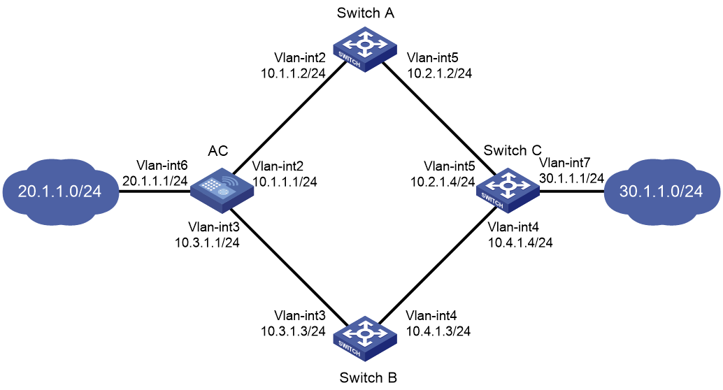
As shown in Figure 3:
· The AC is the default gateway of the hosts in network 20.1.1.0/24.
· Switch C is the default gateway of the hosts in network 30.1.1.0/24.
· Hosts in the two networks communicate with each other through static routes.
To ensure network availability, configure route backup and static routing-Track-NQA collaboration on the AC and Switch C as follows:
· On the AC, assign a higher priority to the static route to 30.1.1.0/24 with next hop Switch A. This route is the master route. The static route to 30.1.1.0/24 with next hop Switch B acts as the backup route. When the master route is unavailable, the backup route takes effect.
· On Switch C, assign a higher priority to the static route to 20.1.1.0/24 with next hop Switch A. This route is the master route. The static route to 20.1.1.0/24 with next hop Switch B acts as the backup route. When the master route is unavailable, the backup route takes effect.
Procedure
1. Create VLANs and assign ports to them. Configure the IP address of each VLAN interface, as shown in Figure 3. (Details not shown.)
2. Configure the AC:
# Configure a static route to 30.1.1.0/24 with next hop 10.1.1.2 and the default priority (60). Associate this static route with track entry 1.
<AC> system-view
[AC] ip route-static 30.1.1.0 24 10.1.1.2 track 1
# Configure a static route to 30.1.1.0/24 with next hop 10.3.1.3 and priority 80.
[AC] ip route-static 30.1.1.0 24 10.3.1.3 preference 80
# Configure a static route to 10.2.1.4 with next hop 10.1.1.2.
[AC] ip route-static 10.2.1.4 24 10.1.1.2
# Create an NQA operation with administrator name admin and operation tag test.
[AC] nqa entry admin test
# Specify the ICMP echo operation type.
[AC-nqa-admin-test] type icmp-echo
# Specify 10.2.1.4 as the destination address of the operation.
[AC-nqa-admin-test-icmp-echo] destination ip 10.2.1.4
# Specify 10.1.1.2 as the next hop of the operation.
[AC-nqa-admin-test-icmp-echo] next-hop ip 10.1.1.2
# Configure the ICMP echo operation to repeat every 100 milliseconds.
[AC-nqa-admin-test-icmp-echo] frequency 100
# Configure reaction entry 1 so that five consecutive probe failures will trigger collaboration with the Track module.
[AC-nqa-admin-test-icmp-echo] reaction 1 checked-element probe-fail threshold-type consecutive 5 action-type trigger-only
[AC-nqa-admin-test-icmp-echo] quit
# Start the NQA operation.
[AC] nqa schedule admin test start-time now lifetime forever
# Configure track entry 1, and associate it with reaction entry 1 of the NQA operation.
[AC] track 1 nqa entry admin test reaction 1
3. Configure Switch A:
# Configure a static route to 30.1.1.0/24 with next hop 10.2.1.4.
<SwitchA> system-view
[SwitchA] ip route-static 30.1.1.0 24 10.2.1.4
# Configure a static route to 20.1.1.0/24 with next hop 10.1.1.1.
[SwitchA] ip route-static 20.1.1.0 24 10.1.1.1
4. Configure Switch B:
# Configure a static route to 30.1.1.0/24 with next hop 10.4.1.4.
<SwitchB> system-view
[SwitchB] ip route-static 30.1.1.0 24 10.4.1.4
# Configure a static route to 20.1.1.0/24 with next hop 10.3.1.1.
[SwitchB] ip route-static 20.1.1.0 24 10.3.1.1
5. Configure Switch C:
# Configure a static route to 20.1.1.0/24 with next hop 10.2.1.2 and the default priority (60). Associate this static route with track entry 1.
<SwitchC> system-view
[SwitchC] ip route-static 20.1.1.0 24 10.2.1.2 track 1
# Configure a static route to 20.1.1.0/24 with next hop 10.4.1.3 and priority 80.
[SwitchC] ip route-static 20.1.1.0 24 10.4.1.3 preference 80
# Configure a static route to 10.1.1.1 with next hop 10.2.1.2.
[SwitchC] ip route-static 10.1.1.1 24 10.2.1.2
# Create an NQA operation with administrator name admin and operation tag test.
[SwitchC] nqa entry admin test
# Specify the ICMP echo operation type.
[SwitchC-nqa-admin-test] type icmp-echo
# Specify 10.1.1.1 as the destination address of the operation.
[SwitchC-nqa-admin-test-icmp-echo] destination ip 10.1.1.1
# Specify 10.2.1.2 as the next hop of the operation.
[SwitchC-nqa-admin-test-icmp-echo] next-hop ip 10.2.1.2
# Configure the ICMP echo operation to repeat every 100 milliseconds.
[SwitchC-nqa-admin-test-icmp-echo] frequency 100
# Configure reaction entry 1 so that five consecutive probe failures will trigger collaboration with the Track module.
[SwitchC-nqa-admin-test-icmp-echo] reaction 1 checked-element probe-fail threshold-type consecutive 5 action-type trigger-only
[SwitchC-nqa-admin-test-icmp-echo] quit
# Start the NQA operation.
[SwitchC] nqa schedule admin test start-time now lifetime forever
# Configure track entry 1, and associate it with reaction entry 1 of the NQA operation.
[SwitchC] track 1 nqa entry admin test reaction 1
Verifying the configuration
# Display information about the track entry on the AC.
[AC] display track all
Track ID: 1
State: Positive
Duration: 0 days 0 hours 0 minutes 32 seconds
Notification delay: Positive 0, Negative 0 (in seconds)
Tracked object:
NQA entry: admin test
Reaction: 1
Remote IP/URL: 10.2.1.4
Local IP:--
Interface:--
The output shows that the status of the track entry is Positive, indicating that the NQA operation has succeeded and the master route is available.
# Display the routing table of the AC.
[AC] display ip routing-table
Destinations : 10 Routes : 10
Destination/Mask Proto Pre Cost NextHop Interface
10.1.1.0/24 Direct 0 0 10.1.1.1 Vlan2
10.1.1.1/32 Direct 0 0 127.0.0.1 InLoop0
10.2.1.0/24 Static 60 0 10.1.1.2 Vlan2
10.3.1.0/24 Direct 0 0 10.3.1.1 Vlan3
10.3.1.1/32 Direct 0 0 127.0.0.1 InLoop0
20.1.1.0/24 Direct 0 0 20.1.1.1 Vlan6
20.1.1.1/32 Direct 0 0 127.0.0.1 InLoop0
30.1.1.0/24 Static 60 0 10.1.1.2 Vlan2
127.0.0.0/8 Direct 0 0 127.0.0.1 InLoop0
127.0.0.1/32 Direct 0 0 127.0.0.1 InLoop0
The output shows that the AC forwards packets to 30.1.1.0/24 through Switch A.
# Remove the IP address of VLAN-interface 2 on Switch A.
<SwitchA> system-view
[SwitchA] interface vlan-interface 2
[SwitchA-Vlan-interface2] undo ip address
# Display information about the track entry on the AC
[AC] display track all
Track ID: 1
State: Negative
Duration: 0 days 0 hours 0 minutes 32 seconds
Notification delay: Positive 0, Negative 0 (in seconds)
Tracked object:
NQA entry: admin test
Reaction: 1
Remote IP/URL: 10.2.1.4
Local IP:--
Interface:--
The output shows that the status of the track entry is Negative, indicating that the NQA operation has failed and the master route is unavailable.
# Display the routing table of the AC.
[AC] display ip routing-table
Destinations : 10 Routes : 10
Destination/Mask Proto Pre Cost NextHop Interface
10.1.1.0/24 Direct 0 0 10.1.1.1 Vlan2
10.1.1.1/32 Direct 0 0 127.0.0.1 InLoop0
10.2.1.0/24 Static 60 0 10.1.1.2 Vlan2
10.3.1.0/24 Direct 0 0 10.3.1.1 Vlan3
10.3.1.1/32 Direct 0 0 127.0.0.1 InLoop0
20.1.1.0/24 Direct 0 0 20.1.1.1 Vlan6
20.1.1.1/32 Direct 0 0 127.0.0.1 InLoop0
30.1.1.0/24 Static 80 0 10.3.1.3 Vlan3
127.0.0.0/8 Direct 0 0 127.0.0.1 InLoop0
127.0.0.1/32 Direct 0 0 127.0.0.1 InLoop0
The output shows that the AC forwards packets to 30.1.1.0/24 through Switch B. The backup static route has taken effect.
# Verify that hosts in 20.1.1.0/24 can communicate with the hosts in 30.1.1.0/24 when the master route fails.
[AC] ping -a 20.1.1.1 30.1.1.1
Ping 30.1.1.1: 56 data bytes, press CTRL_C to break
Reply from 30.1.1.1: bytes=56 Sequence=1 ttl=254 time=2 ms
Reply from 30.1.1.1: bytes=56 Sequence=2 ttl=254 time=1 ms
Reply from 30.1.1.1: bytes=56 Sequence=3 ttl=254 time=1 ms
Reply from 30.1.1.1: bytes=56 Sequence=4 ttl=254 time=2 ms
Reply from 30.1.1.1: bytes=56 Sequence=5 ttl=254 time=1 ms
--- Ping statistics for 30.1.1.1 ---
5 packet(s) transmitted, 5 packet(s) received, 0.00% packet loss
round-trip min/avg/max/std-dev = 1/1/2/1 ms
# Verify that the hosts in 30.1.1.0/24 can communicate with the hosts in 20.1.1.0/24 when the master route fails.
[SwitchA] ping -a 30.1.1.1 20.1.1.1
Ping 20.1.1.1: 56 data bytes, press CTRL_C to break
Reply from 20.1.1.1: bytes=56 Sequence=1 ttl=254 time=2 ms
Reply from 20.1.1.1: bytes=56 Sequence=2 ttl=254 time=1 ms
Reply from 20.1.1.1: bytes=56 Sequence=3 ttl=254 time=1 ms
Reply from 20.1.1.1: bytes=56 Sequence=4 ttl=254 time=1 ms
Reply from 20.1.1.1: bytes=56 Sequence=5 ttl=254 time=1 ms
--- Ping statistics for 20.1.1.1 ---
5 packet(s) transmitted, 5 packet(s) received, 0.00% packet loss
round-trip min/avg/max/std-dev = 1/1/2/1 ms