- Table of Contents
- Related Documents
-
| Title | Size | Download |
|---|---|---|
| 01-Text | 2.94 MB |
iFIST features and functionality
Preparing for an iFIST sign-in
Prerequisites for a direct iFIST sign-in
Prerequisites for a iFIST sign-in through the HDM remote console
General restrictions and guidelines
Triggering automated operating system installation
Viewing server module information
View and export the diagnostics test result
Example: Updating iFIST on a server in UEFI boot mode
iFIST overview
iFIST enables you to perform a range of configuration and management tasks on the local server from a simple, unified Web interface, including:
· Configuring RAID arrays.
· Automatically installing operating systems.
· Intelligent diagnostics.
· Managing configurations.
· Downloading logs.
· Updating firmware.
iFIST features and functionality
iFIST provides the following features and functionality:
System installation
Traditionally, administrators must go to different feature pages to complete a complicated set of tasks in order to install an operating system on a server.
iFIST integrates the OS installation tasks into the OS installation wizard that guides you through the installation process step-by-step from a unified interface. The OS installation wizard reduces operation complexity and chances of misconfigurations.
Through the iFIST OS installation wizard, you can configure RAID arrays, install drivers, and export and import configuration files. After the installation configuration is complete, iFIST automatically installs the operating system on the server.
Intelligent diagnostics
Use this function to perform the following tasks:
· Server Diagnostics—Scans the components on the server to collect statistics for component-based performance and health diagnosis. It facilitates server troubleshooting and reduces the risks of unexpected problems during server usage. Server Diagnostics supports diagnosing various components on the server, including the CPU, PSU, fan, HDM, memory, and PCIe devices.
· Memory Smart-Test—Tests and repairs the memory in the POST memory initialization stage through the memory test tool embedded in the BIOS.
Configuration management
Use this function to perform the following tasks:
· Import configuration—Import the HDM, BIOS, or RAID configuration file in a USB flash drive to the system to overwrite the existing configuration.
· Export configuration—Export the current HDM, BIOS, or RAID configuration, generate a configuration file, and save it in the iFIST/ConfManage directory in the root directory of the USB flash drive.
· ACS configuration—Configure ACS capability and ACS control.
Download logs
Use this function to download the OS logs, SDS logs, storage controller logs, and hard disk logs and save the logs to the iFIST/LogDownload directory of a USB flash drive inserted into the server.
Firmware update
Use this function to update firmware for the server and components, including HDM, BIOS, CPLD, storage controllers, network adapters, and drives.
Applicable scenarios
When access to a remote HDM system is not available, you can use iFIST for in-band local server management.
To use iFIST on a server, you must connect a monitor, a keyboard, and a mouse to the server.
Applicable products
This guide is applicable to the following products:
· H3C UniServer R2700 G3
· H3C UniServer R2900 G3
· H3C UniServer R4500 G3
· H3C UniServer R4700 G3
· H3C UniServer R4900 G3
· H3C UniServer R4950 G3 Naples
· H3C UniServer R4950 G3 Rome
· H3C UniServer R5300 G3
· H3C UniServer R6700 G3
· H3C UniServer R6900 G3
· H3C UniServer R8900 G3
· H3C UniServer B5700 G3
· H3C UniServer B5800 G3
· H3C UniServer B7800 G3
· H3C UniServer E3200 G3
· H3C UniServer R4300 G5
· H3C UniServer R4330 G5
· H3C UniServer R4700 G5
· H3C UniServer R4900 G5
· H3C UniServer R4930 G5
· H3C UniServer R4950 G5 Rome
· H3C UniServer R5300 G5
· H3C UniServer R5500 G5
· H3C UniServer R6900 G5
· H3C UniServer B5700 G5
Guidelines
The information in this document might differ from your product if it contains custom configuration options or features.
The model name of a hardware option in this document might differ slightly from its model name label. A model name label might add a prefix or suffix to the hardware-coded model name for purposes such as identifying the matching server brand or applicable region. For example, storage controller model HBA-1000-M2-1 represents storage controller model label UN-HBA-1000-M2-1, which has a prefix of UN-.
The webpage screenshots used in this document are for illustration only and might differ from your products.
To obtain help information when you use
iFIST, click the question mark icon ![]() at the
upper right of the webpage.
at the
upper right of the webpage.
Signing in to iFIST
Preparing for an iFIST sign-in
You can sign in to iFIST on a server either directly or from the remote console of the HDM Web interface.
The following information describes the prerequisites for a successful sign-in to iFIST.
Prerequisites for a direct iFIST sign-in
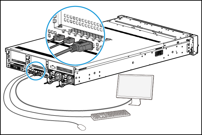
To sign in to iFIST on a server directly, you must connect a monitor, a mouse, and a keyboard to the server.
For a rack server such as an H3C UniServer R4900 G3 server:
· Connect the monitor to the server through the VGA connector.
· Connect the mouse and keyboard to the server through the USB connectors.
Figure 1 Connecting a monitor, a mouse, and a keyboard to a rack server
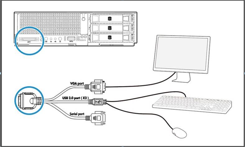
For a blade server such as an H3C UniServer B5800 G3 server, connect the monitor, mouse, and keyboard to the server through SUV connectors, as shown in Figure 2.
Figure 2 Connecting a monitor, a mouse, and a keyboard to a blade server
Prerequisites for a iFIST sign-in through the HDM remote console
Prepare the hardware environment for signing in to iFIST through HDM. For more information, see H3C Servers HDM User Guide.
Procedure
1. Launch the remote console from the HDM Web interface. For more information, see H3C Servers HDM Quick Start Guide.
Skip this step if a local direct KVM connection is used.
2. Reboot the server.
3. On the POST screen shown in Figure 3, press F10.
Figure 3 Launching iFIST from the POST screen (BIOS version 2.00.26)
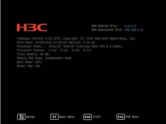
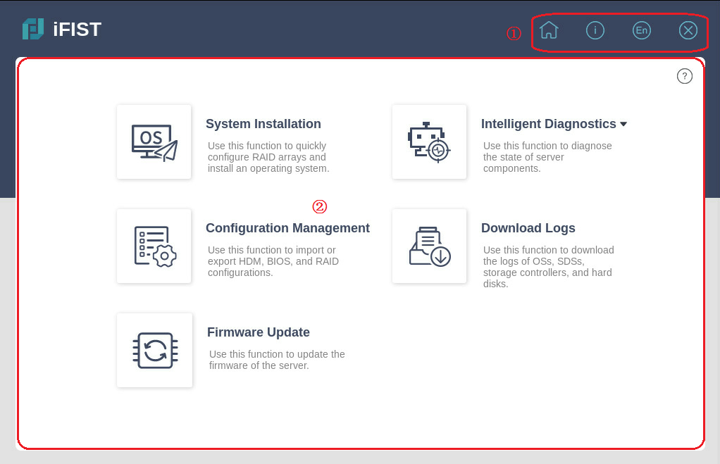
The Web interface of iFIST is displayed, as shown in Figure 4.
iFIST Web interface
As shown in Figure 4, the iFIST Web interface contains the following areas:
|
Area |
Description |
|
Administrative section |
Provides the following management options: · · · · |
|
Work pane |
Displays links to the functions provided by iFIST. To obtain help information when you use
iFIST, click the question mark icon |
Figure 4 iFIST Web interface
System installation
Supported operating systems
You can install the following types of operating systems through the iFIST OS installation wizard:
· Red Hat Enterprise Linux.
· SuSE Linux Enterprise Server.
· CentOS.
· Ubuntu Server.
· VMware ESXi.
· CAS.
· Oracle Linux.
· Windows Server (except Windows Core OS).
Table 1 lists the operating systems and their versions that can be installed through the iFIST OS installation wizard.
Table 1 Supported operating systems
|
Version |
|
|
Red Hat Enterprise Linux |
Red Hat Enterprise Linux 6.7 (64 bit) (includes KVM) |
|
Red Hat Enterprise Linux 6.8 (64 bit) (includes KVM) |
|
|
Red Hat Enterprise Linux 6.9 (64 bit) (includes KVM) |
|
|
Red Hat Enterprise Linux 6.10 (64 bit) (includes KVM) |
|
|
Red Hat Enterprise Linux 7.2 (64 bit) (includes KVM) |
|
|
Red Hat Enterprise Linux 7.3 (64 bit) (includes KVM) |
|
|
Red Hat Enterprise Linux 7.4 (64 bit) (includes KVM) |
|
|
Red Hat Enterprise Linux 7.5 (64 bit) (includes KVM) |
|
|
Red Hat Enterprise Linux 7.6 (64 bit) (includes KVM) |
|
|
Red Hat Enterprise Linux 7.7 (64 bit) (includes KVM) |
|
|
Red Hat Enterprise Linux 7.8 (64 bit) (includes KVM) |
|
|
Red Hat Enterprise Linux 7.9 (64 bit) (includes KVM) |
|
|
Red Hat Enterprise Linux 8.0 (64 bit) (includes KVM) |
|
|
Red Hat Enterprise Linux 8.1 (64 bit) (includes KVM) |
|
|
Red Hat Enterprise Linux 8.2 (64 bit) (includes KVM) |
|
|
Red Hat Enterprise Linux 8.3 (64 bit) (includes KVM) |
|
|
Red Hat Enterprise Linux 8.4 (64 bit) (includes KVM) |
|
|
SuSE Linux Enterprise Server |
SLES 11 SP4 (64 bit) (includes XEN & KVM) |
|
SLES 12 (64 bit) SP1 (includes XEN & KVM) |
|
|
SLES 12 (64 bit) SP2 (includes XEN & KVM) |
|
|
SLES 12 (64 bit) SP3 (includes XEN & KVM) |
|
|
SLES 12 (64 bit) SP4 (includes XEN & KVM) |
|
|
SLES 12 (64 bit) SP5 (includes XEN & KVM) |
|
|
SLES 15 (64 bit) (includes XEN & KVM) |
|
|
SLES 15 (64 bit) SP1 (includes XEN & KVM) |
|
|
CentOS |
CentOS 6.10 (64 bit) |
|
CentOS 7.3 (64 bit) |
|
|
CentOS 7.4 (64 bit) |
|
|
CentOS 7.5 (64 bit) |
|
|
CentOS 7.6 (64 bit) |
|
|
CentOS 7.7 (64 bit) |
|
|
CentOS 7.8 (64 bit) |
|
|
CentOS 7.9 (64 bit) |
|
|
CentOS 8.0 (64 bit) |
|
|
CentOS 8.1 (64 bit) |
|
|
CentOS 8.2 (64 bit) |
|
|
CentOS 8.3 (64 bit) |
|
|
CentOS 8.4 (64 bit) |
|
|
VMware ESXi |
VMware ESXi 6.5 U1 (64 bit) |
|
VMware ESXi 6.5 U2 (64 bit) |
|
|
VMware ESXi 6.5 U3 (64 bit) |
|
|
VMware ESXi 6.7 (64 bit) |
|
|
VMware ESXi 6.7 U3 (64 bit) |
|
|
VMware ESXi 7.0 (64 bit) |
|
|
Ubuntu Server |
Ubuntu Server 17.10 (64 bit) – LTS |
|
Ubuntu Server 18.4 (64 bit) – LTS |
|
|
CAS |
CAS 5.0 |
|
Oracle Linux |
Oracle Linux 8.2 |
|
Windows Server |
Microsoft Windows Server 2012 R2 Datacenter |
|
Microsoft Windows Server 2012 R2 Essentials |
|
|
Microsoft Windows Server 2012 R2 Standard |
|
|
Microsoft Hyper-V Server 2012 R2 |
|
|
Microsoft Windows Server 2016 Essential |
|
|
Microsoft Windows Server 2016 Standard |
|
|
Microsoft Windows Server 2016 Datacenter |
|
|
Microsoft Hyper-V Server 2016 |
|
|
Microsoft Hyper-V Server 2019 |
|
|
Microsoft Windows Server 2019 Standard |
|
|
Microsoft Windows Server 2019 Datacenter |
Supported storage controllers
The iFIST system installation supports the following types of storage controllers:
· HBA-1000-M2-1
· RAID-P430-M1
· RAID-P430-M2
· HBA-H460-M1
· RAID-P460-M4
· HBA-H460-B1
· RAID-P460-B4
· HBA-LSI-9311-8i-A1-X
· RAID-LSI-9361-8i(1G)-A1-X
· RAID-LSI-9361-8i(2G)-1-X
· RAID-LSI-9460-8i(2G)
· RAID-LSI-9460-8i(4G)
· RAID-LSI-9460-16i(4G)
· RAID-L460-M4
· RAID-P5408-Mf-8i-4GB
· HBA-H5408-Mf-8i
· HBA-LSI-9440-8i
· HBA-LSI-9300-8i-A1-X
· RAID-P4408-Mf-8i-2GB
· RAID-P2404-Mf-4i-2GB
· RAID-P5408-Ma-8i-4GB
· RAID-P4408-Ma-8i-2GB
· RAID-P460-B2
· RAID-P460-M2
· RAID-LSI-9560-LP-16i-8GB
· RAID-LSI-9560-LP-8i-4GB
· HBA-LSI-9400-8i
· HBA-LSI-9400-16i
iFIST built-in drivers
When you install an operating system on a server through iFIST, the available built-in drivers of iFIST vary by operating system, as shown in Table 2 and Table 3.
Table 2 iFIST built-in drivers for Windows
|
Driver name |
Driver version |
Supported OSs |
|
FC-HBA-LPe |
12.8.334.6 |
· Microsoft Windows Server 2012 R2 · Microsoft Windows Server 2016 · Microsoft Windows Server 2019 |
|
RAID-9361-8i |
6.714.18.00 |
· Microsoft Windows Server 2012 R2 · Microsoft Windows Server 2016 · Microsoft Windows Server 2019 |
|
LSI-9300-9311 |
2.51.26.00 |
· Microsoft Windows Server 2012 R2 · Microsoft Windows Server 2016 · Microsoft Windows Server 2019 |
|
LSI-MR-IMR |
7.708.18.0 |
Microsoft Windows Server 2012 R2 |
|
7.715.4.0 |
· Microsoft Windows Server 2016 · Microsoft Windows Server 2019 |
|
|
NIC-360T |
12.14.7.0 |
Microsoft Windows Server 2012 R2 |
|
12.15.184.13 |
Microsoft Windows Server 2016 |
|
|
12.18.9.6 |
Microsoft Windows Server 2019 |
|
|
NIC-530F |
7.13.161.0 |
Microsoft Windows Server 2012 R2 |
|
7.13.171.0 |
· Microsoft Windows Server 2016 · Microsoft Windows Server 2019 |
|
|
NIC-Intel500 |
3.14.214.0 |
Microsoft Windows Server 2012 R2 |
|
4.1.196.0 |
· Microsoft Windows Server 2016 · Microsoft Windows Server 2019 |
|
|
NIC-Intel700 |
1.11.101.0 |
· Microsoft Windows Server 2012 R2 · Microsoft Windows Server 2016 · Microsoft Windows Server 2019 |
|
PMC-ARC-THOR |
7.5.0.57011 |
Microsoft Windows Server 2012 R2 |
|
7.5.0.59002 |
· Microsoft Windows Server 2016 · Microsoft Windows Server 2019 |
|
|
PMC-LUXOR |
106.278.0.1043 |
· Microsoft Windows Server 2012 R2 · Microsoft Windows Server 2016 · Microsoft Windows Server 2019 |
|
ASPEED-Graphics-Family (Available only for R2700 G3, R2900 G3, R4700 G3, and R4900 G3) |
1.01 |
Microsoft Windows Server 2012 R2 |
Table 3 iFIST built-in drivers for Windows
|
Driver name |
Driver version |
Supported OSs |
|
FC-HBA-LPe |
12.6.240.27 |
· Red Hat Enterprise Linux 7.6 (64 bit) (includes KVM) · CentOS 7.6 (64 bit) |
|
12.8.340.9 |
· Red Hat Enterprise Linux 7.8 (64 bit) (includes KVM) · Red Hat Enterprise Linux 7.9 (64 bit) (includes KVM) · Red Hat Enterprise Linux 8.1 (64 bit) (includes KVM) · CentOS 7.8 (64 bit) · CentOS 7.9 (64 bit) · CentOS 8.1 (64 bit) |
|
|
12.8.351.46 |
· Red Hat Enterprise Linux 8.2 (64 bit) (includes KVM) · CentOS 8.2 (64 bit) |
|
|
12.6.240.53 |
· Red Hat Enterprise Linux 8.3 (64 bit) (includes KVM) · CentOS 8.3 (64 bit) |
|
|
RAID-9361-8i |
07.715.02.00 |
· Red Hat Enterprise Linux 7.6 (64 bit) (includes KVM) · Red Hat Enterprise Linux 7.8 (64 bit) (includes KVM) · Red Hat Enterprise Linux 8.1 (64 bit) (includes KVM) · Red Hat Enterprise Linux 8.2 (64 bit) (includes KVM) · CentOS 7.6 (64 bit) · CentOS 7.8 (64 bit) · CentOS 8.1 (64 bit) · CentOS 8.2 (64 bit) |
|
07.716.01.00 |
· Red Hat Enterprise Linux 7.9 (64 bit) (includes KVM) · CentOS 7.9 (64 bit) |
|
|
LSI-9300-9311 |
33.00.00.00 |
· Red Hat Enterprise Linux 7.6 (64 bit) (includes KVM) · Red Hat Enterprise Linux 8.1 (64 bit) (includes KVM) · CentOS 7.6 (64 bit) · CentOS 8.1 (64 bit) |
|
36.00.00.00 |
· Red Hat Enterprise Linux 8.2 (64 bit) (includes KVM) · CentOS 8.2 (64 bit) |
|
|
LSI-MR-IMR |
07.717.02.00 |
· Red Hat Enterprise Linux 7.6 (64 bit) (includes KVM) · Red Hat Enterprise Linux 7.8 (64 bit) (includes KVM) · Red Hat Enterprise Linux 7.9 (64 bit) · Red Hat Enterprise Linux 8.1 (64 bit) (includes KVM) · Red Hat Enterprise Linux 8.2 (64 bit) (includes KVM) · Red Hat Enterprise Linux 8.3 (64 bit) (includes KVM) · CentOS 7.6 (64 bit) · CentOS 7.8 (64 bit) · CentOS 7.9 (64 bit) · CentOS 8.1 (64 bit) · CentOS 8.2 (64 bit) · CentOS 8.3 (64 bit) |
|
NIC-360T |
5.3.5.39 |
· Red Hat Enterprise Linux 7.6 (64 bit) (includes KVM) · Red Hat Enterprise Linux 7.8 (64 bit) (includes KVM) · Red Hat Enterprise Linux 8.1 (64 bit) (includes KVM) · CentOS 7.6 (64 bit) · CentOS 7.8 (64 bit) · CentOS 8.1 (64 bit) |
|
5.3.5.61 |
· Red Hat Enterprise Linux 8.2 (64 bit) (includes KVM) · CentOS 8.2 (64 bit) |
|
|
NIC-530F |
1.714.25.1 |
· Red Hat Enterprise Linux 7.6 (64 bit) (includes KVM) · CentOS 7.6 (64 bit) |
|
1.715.0 |
· Red Hat Enterprise Linux 7.8 (64 bit) (includes KVM) · Red Hat Enterprise Linux 8.1 (64 bit) (includes KVM) · CentOS 7.8 (64 bit) · CentOS 8.1 (64 bit) |
|
|
1.715.4.1 |
· Red Hat Enterprise Linux 7.9 (64 bit) (includes KVM) · Red Hat Enterprise Linux 8.2 (64 bit) (includes KVM) · CentOS 7.9 (64 bit) · CentOS 8.2 (64 bit) |
|
|
NIC-Intel500 |
5.6.5 |
· Red Hat Enterprise Linux 7.6 (64 bit) (includes KVM) · Red Hat Enterprise Linux 8.1 (64 bit) (includes KVM) · CentOS 7.6 (64 bit) · CentOS 8.1 (64 bit) |
|
5.9.4 |
· Red Hat Enterprise Linux 7.8 (64 bit) (includes KVM) · Red Hat Enterprise Linux 7.9 (64 bit) (includes KVM) · Red Hat Enterprise Linux 8.3 (64 bit) (includes KVM) · CentOS 7.8 (64 bit) · CentOS 7.9 (64 bit) · CentOS 8.3 (64 bit) |
|
|
5.7.1 |
· Red Hat Enterprise Linux 8.2 (64 bit) (includes KVM) · CentOS 8.2 (64 bit) |
|
|
NIC-Intel700 |
2.15.9 |
· Red Hat Enterprise Linux 7.6 (64 bit) (includes KVM) · Red Hat Enterprise Linux 7.8 (64 bit) (includes KVM) · Red Hat Enterprise Linux 7.9 (64 bit) (includes KVM) · Red Hat Enterprise Linux 8.1 (64 bit) (includes KVM) · Red Hat Enterprise Linux 8.2 (64 bit) (includes KVM) · Red Hat Enterprise Linux 8.3 (64 bit) (includes KVM) · CentOS 7.6 (64 bit) · CentOS 7.8 (64 bit) · CentOS 7.9 (64 bit) · CentOS 8.1 (64 bit) · CentOS 8.2 (64 bit) · CentOS 8.3 (64 bit) |
|
PMC-ARC-THOR |
1.2.1.59002 |
· Red Hat Enterprise Linux 7.6 (64 bit) (includes KVM) · Red Hat Enterprise Linux 8.1 (64 bit) (includes KVM) · CentOS 7.6 (64 bit) · CentOS 8.1 (64 bit) |
|
PMC-LUXOR |
2.1.8-040 |
· Red Hat Enterprise Linux 7.6 (64 bit) (includes KVM) · Red Hat Enterprise Linux 7.8 (64 bit) (includes KVM) · Red Hat Enterprise Linux 7.9 (64 bit) (includes KVM) · Red Hat Enterprise Linux 8.1 (64 bit) (includes KVM) · Red Hat Enterprise Linux 8.2 (64 bit) (includes KVM) · Red Hat Enterprise Linux 8.3 (64 bit) (includes KVM) · CentOS 7.6 (64 bit) · CentOS 7.8 (64 bit) · CentOS 7.9 (64 bit) · CentOS 8.1 (64 bit) · CentOS 8.2 (64 bit) · CentOS 8.3 (64 bit) |
General restrictions and guidelines
To determine the chip type of the storage controller, see H3C Servers Storage Controller User Guide.
Make sure only one bootable medium is mounted to the server. If more than one bootable medium is mounted, the server might fail to identify the correct boot media, and operating system installation will fail as a result.
The OS installation wizard supports the following controllers:
· PMC controllers in RAID (Hide-RAW), HBA, or Mixed mode. RAID-P430-M1 or RAID-P430-M2 controllers in RAID (Hide-RAW) or RAID (Expose-RAW) mode.
· LSI controllers in RAID mode.
You can change the image source only in the basic settings step. After the installation starts, do not remove the image source or intervene manually.
To install an operating system on a server in UEFI boot mode, make sure only the system drive (target logical drive) contains a UEFI partition. Operating system installation will fail if a UEFI partition exists on a non-system drive.
The OS installation wizard does not support OS installation or RAID configuration on the onboard RAID controller.
Prerequisites
Before using the OS installation wizard, complete the following tasks:
· Mount the storage media that contains the OS image to the server. Supported storage media include CD (physical CD or HDM virtual media) and USB flash drive.
· If driver installation is required, mount to the server the storage media that contains a REPO image file in a format matching the ISO image format. iFIST cannot recognize compressed driver installation packages.
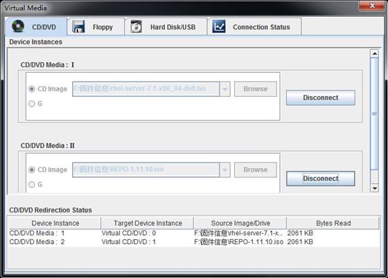
· If iFIST is accessed through the HDM remote console, you must mount both the OS image file and REPO image file to the HDM remote console.
Figure 5 shows an example of mounting to the KVM remote console the OS image file and REPO image file stored on a virtual CD.
Figure 5 Mounting the OS image file and REPO image file
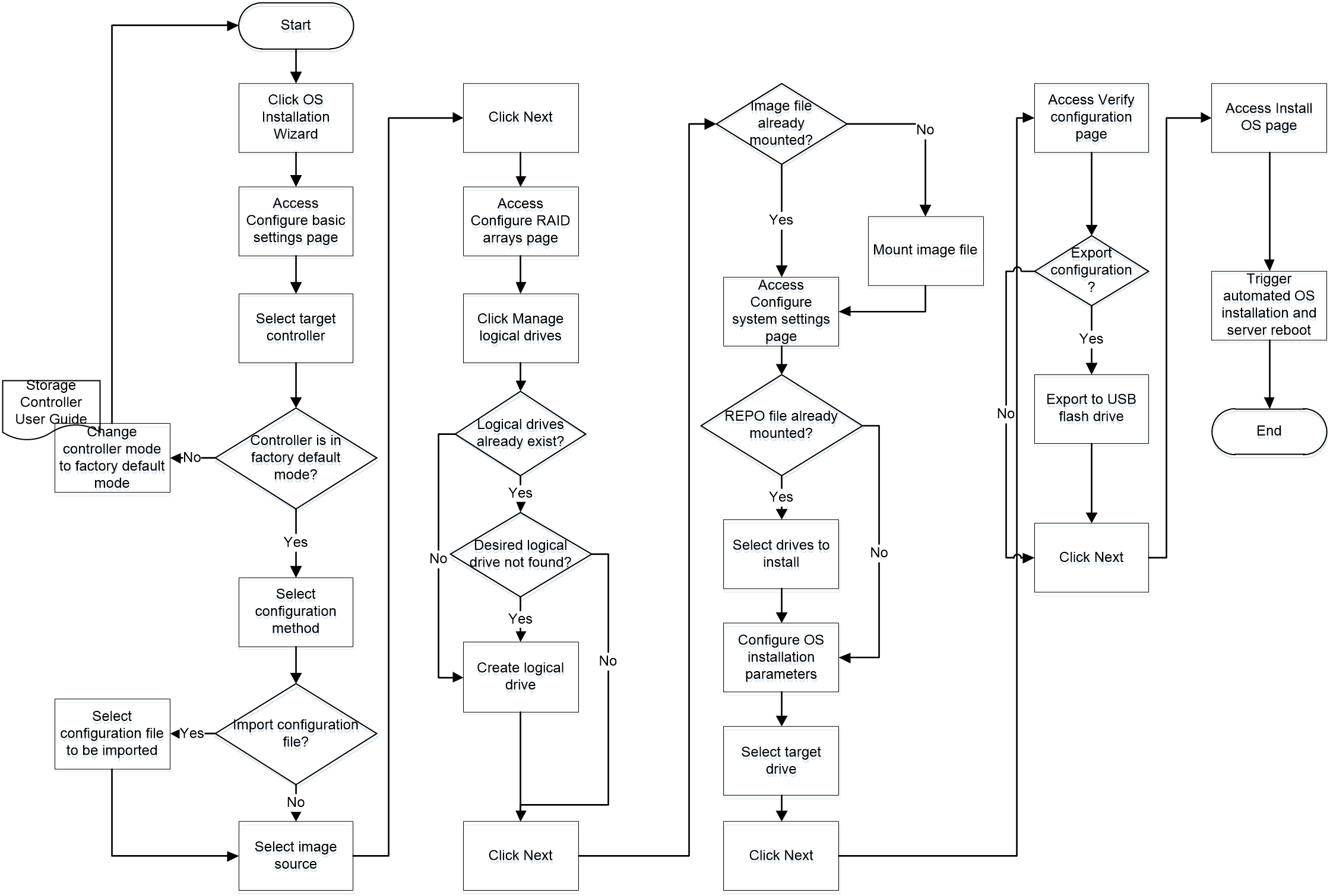
OS installation workflow
Figure 6 shows the workflow of using the OS installation wizard to install an operating system.
Figure 6 OS installation workflow
Configuring basic settings
The configuration parameters in this task vary by the storage controller used.
Procedure
1. On the iFIST home page, click System Installation.
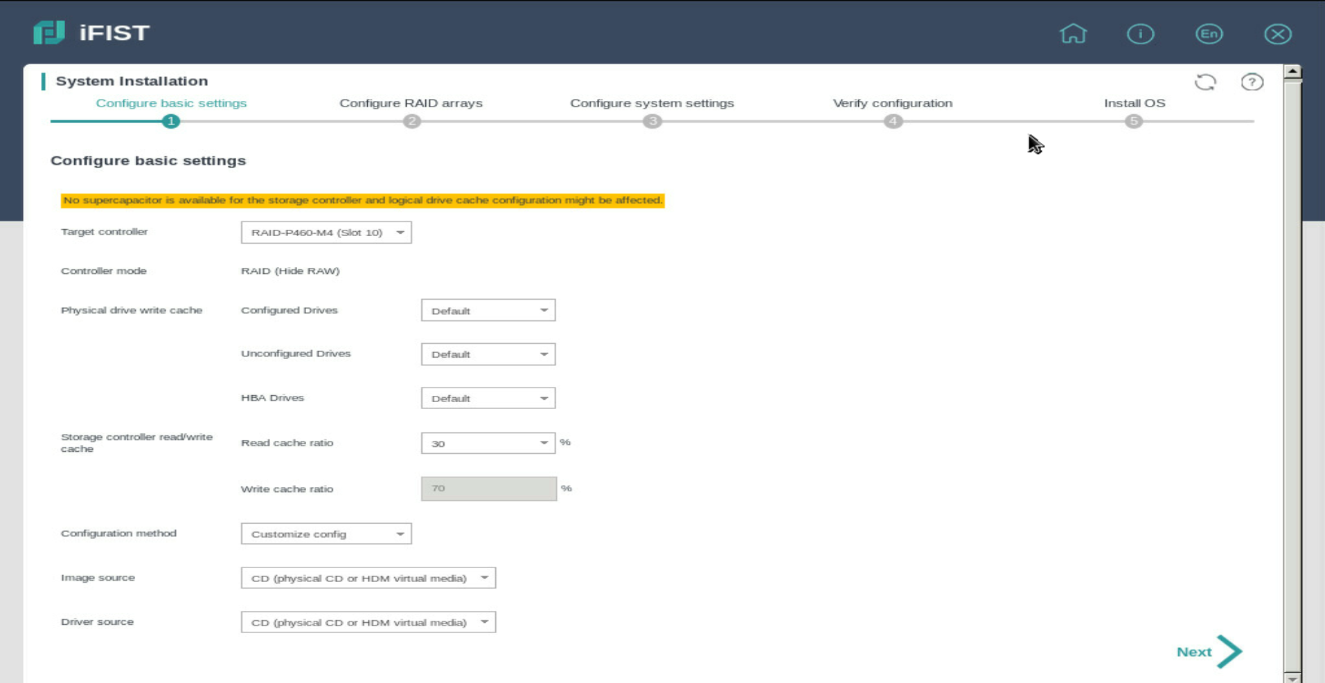
The OS installation wizard displays the Configure basic settings page, as shown in Figure 7.
For descriptions of the parameters on the page, see "Parameters."
Figure 7 Configuring basic settings
2. Select the storage controller to be configured from the Target controller list.
Before you install an OS, make sure the OS installation is supported. For information about the operating system compatibility, contact Technical Support.
3. Check the Controller mode field to verify that the controller is operating in the supported mode.
If a PMC controller is used, the controller mode must be RAID (Hide-RAW), HBA, or Mixed.
If an LSI controller is used, the controller mode must be RAID.
4. From the Global write cache list, select a global write cache mode for the physical drives attached to the controller. Alternatively, set the write cache mode for drives in the Physical drive write cache area.
5. Set the read cache ratio and write cache ratio in the Storage controller read/write cache field.
6. From the Configuration method list, select Customize config or Import config file.
7. If Import config file is selected, specify the location of the configuration file to be imported.
The configuration file to be imported must meet the following requirements:
¡ The file must meet the validation criteria described in "Configuration file validation." Verify the file against the validation criteria before the import.
¡ The file must be stored on a USB flash drive formatted with the FAT32 or NTFS file system.
If the Import config file configuration method is used, iFIST automatically creates the logical drives by using all the available capacities of the member drives on the server. The logical drive capacity settings in the configuration file are not imported.
Select the Import config file configuration method with caution because the imported configuration file will overwrite all the existing RAID settings.
8. Select the type of media where the OS image file resides. Options are CD (physical CD or HDM virtual media) and USB flash drive.
9. (Optional.) Select the driver source. Options are CD (physical CD or HDM virtual media) and USB flash drive.
10. Click Next.
Parameters
· Target controller—Select the storage controller to be configured.
· Controller mode—Verify that the operating mode of the selected storage controller is supported by iFIST.
For a PMC controller, the controller mode must be RAID (Hide-RAW), HBA, or Mixed.
For an LSI controller, the controller mode must be RAID.
· JBOD—Indicates whether the Just a Bunch Of Disks (JBOD) mode is enabled or disabled. The value can be ON or OFF.
¡ ON—The JBOD mode is enabled. The operating system can have access to a disk directly without creating a RAID volume first.
¡ OFF—The JBOD mode is disabled. The operating system is not able to see a disk until the disk in included in a RAID volume.
This parameter is not displayed if the storage controller does not support the JBOD attribute.
· Global write cache—This parameter is displayed only if it is supported by the selected storage controller. Set the global write cache mode for the physical drives attached to the storage controller. Options are:
¡ Enabled—Enables write cache for all physical drives. Enabling write cache for physical drives improves the system's read and write performance.
¡ Disabled—Disables write cache for all physical drives. Write cache is typically disabled for physical drives used to build logical drives to prevent data loss in case of power failures.
¡ Drive specific—Sets the write cache policy for physical drives individually.
· Physical drive write cache—This parameter is displayed only if it is supported by the selected storage controller. Set the write cache mode for the following types of drives separately.
¡ Configured Drives—Configured physical drives attached to the controllers operating in RAID or Mixed mode.
¡ Unconfigured Drives—Unconfigured physical drives attached to the controllers operating in RAID or Mixed mode.
¡ HBA Drives—Physical drives attached to storage controllers operating in HBA mode.
Supported write cache modes are:
¡ Default—Uses the default write cache mode for physical drives.
¡ Enabled—Enables write cache for physical drives.
¡ Disabled—Disables write cache for physical drives.
· Storage controller read/write cache—Set the read cache ratio and write cache ratio. This parameter is displayed only for the following PMC storage controllers:
¡ RAID-P460-M4.
¡ RAID-P460-B4.
¡ RAID-P460-M2.
¡ RAID-P460-B2.
¡ RAID-P4408-Mf-8i-2GB.
¡ RAID-P4408-Ma-8i-2GB.
¡ RAID-P2404-Mf-4i-2GB.
· Configuration method—Select the method for configuring RAID and operating system installation parameters. Options are:
¡ Customize config—Manually configures RAID and operating system installation settings.
¡ Import config file—Imports the settings from a configuration file stored on a floppy drive or a USB flash drive mounted to the server.
· Image source—Select the type of media where the image file resides. Options are CD (physical CD or HDM virtual media) and USB flash drive.
If you select USB flash drive, iFIST displays the paths of image files detected on the USB flash drive in a list next to this field. Select an image file from the list.
Follow these guidelines when you configure the image source parameters:
¡ To install the SuSE Linux Enterprise Server operating system, make sure the following conditions are met:
- The image file resides on a USB flash drive partition formatted with the FAT32 file system.
- The pathname of the image file (including the image file name) does not contain Chinese characters or spaces.
¡ To install the Red Hat Enterprise Linux operating system, make sure the following conditions are met:
- The image file resides on a USB flash drive partition formatted with the FAT32 or EXT2/3/4 file system.
- The pathname of the image file (including the path file name) does not contain spaces.
¡ To install the CentOS operating system, make sure the following conditions are met:
- The image file resides on a USB flash drive partition formatted with the FAT32 or EXT2/3/4 file system. If a USB flash drive partition is formatted with the FAT32 file system, make sure the image file size does not exceed 4 GB.
- The pathname of the image file (including the image file name) does not contain Chinese characters or spaces.
¡ To install the Red Hat Enterprise Linux 6.7/6.8/6.9 or CentOS 6.10 operating system, make sure the following conditions are met:
- The USB flash drive partition where the image file resides has 300 MB or more free space.
- To avoid installation failure, save only one ISO image file in the image file directory.
¡ To install the Ubuntu Server or CAS operating system, make sure the image source is CD (physical CD or HDM virtual media).
¡ To install the VMware ESXi operating system, make sure the image file resides on a USB flash drive partition formatted with the FAT32 or NTFS file system.
¡ To install the Windows Server operating system, make sure the image file resides on a USB flash drive partition formatted with the NTFS file system.
¡ To install the Oracle Linux operating system, make sure the following conditions are met:
- The image file resides on a USB flash drive partition formatted with the EXT2/3/4 file system.
- The pathname of the image file (including the image file name) contains only letters and digits.
· Driver source—Select the storage medium where the REPO image resides. Options are CD (physical CD or HDM virtual media) and USB flash drive.
Configuration file validation
To ensure successful configuration file import into a server, make sure the following conditions are met:
· For a server installed with multiple storage controllers, make sure the following conditions are met:
¡ The number of installed storage controllers must be equal to or greater than the number of storage controllers specified in the configuration file.
¡ The type, mode, and slot specified for each storage controller in the configuration file must match the type, mode, and slot of each storage controller installed in the server.
· If you fail to import the configuration file to a server installed with multiple storage controllers, you can use other methods to install OS to the storage controllers.
· For each logical drive in the file, all the member physical drives must be present on the corresponding slots of the server and must meet the following requirements:
¡ If a PMC controller is used, the drives must be in Raw, Ready, or Online state.
¡ If an LSI controller is used, the drives must be in Unconfigured Good, Unconfigured Bad, or Online state. The physical drives of an HBA-LSI-9300-8i-A1-X controller must be in Ready state. The physical drives of an HBA-LSI-9311-8i-A1-X controller must be in Ready or Optimal state.
Configuring RAID arrays
|
|
IMPORTANT: · To install an operating system on a physical drive, directly click Next on the Create RAID array tab to skip the RAID configuration procedure and go to the system settings step. · Hot spare management is supported only on the RAID-P460-B2 storage controller with firmware version 4.11. If an error occurs on hot spare management for the storage controller with another version, update the firmware version of the storage controller first. |
RAID array configuration involves the following tasks:
· Create RAID arrays—Create RAID arrays by using physical drives in Ready state on the server.
· Manage physical drives—Initialize and uninitialize physical drives, and set the cache mode for physical drives.
· Manage logical drives—Set the cache mode for the logical drives and delete logical drives as needed.
Creating a RAID array
Procedure
1. On the Manage logical drives tab, identify whether the logical drive on which you want to install the operating system already exists. If the logical drive already exists, click Next to go to the next step directly.
If the logical drive list does not contain such a logical drive, perform the following steps to create one first.
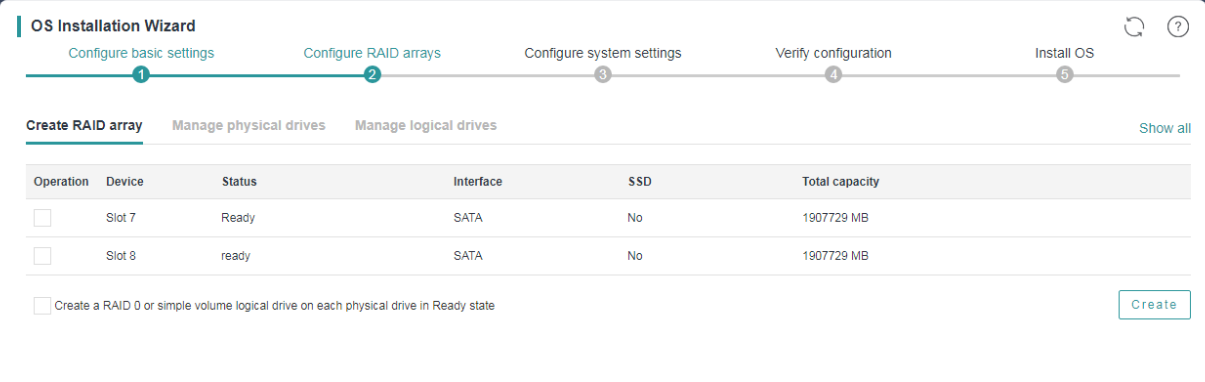
2. On the Configure RAID arrays page, click the Create RAID array tab.
Figure 8 Create RAID array tab
3. To create a RAID array:
a. Select one or more physical drives.
b. Click Create.
The Create RAID Array window opens, as shown in Figure 9.
For descriptions of the parameters on this window, see "Parameters."
Figure 9 Create RAID Array window (HBA controller)
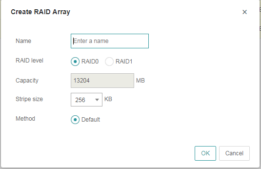
a. Set the name, RAID level, stripe size, and initialization method for the RAID array.
b. Click OK.
4. To create a RAID 0 or simple volume logical drive on each physical drive in Ready or Unconfigured Good state:
a. Select the Create a RAID 0 or simple volume logical drive on each physical drive in Ready state option.
b. Click Create.
c. In the confirmation dialog box that opens, click OK.
This feature is not available if an HBA-LSI-9311-8i-A1-X controller is used.
Parameters
· Name—Name of the RAID array.
· RAID level—RAID level.
· Capacity—This field is automatically populated with the maximum capacity of the RAID array, which cannot be modified.
· Stripe size—Data block size written to each physical drive in the RAID array. The default is 256 KB.
· Method—Initialization method of the RAID array.
· Write cache—This field is supported by RAID controllers only.
· Read cache—This field is supported by RAID controllers only.
Managing physical drives
About physical drive management
To use physical drives to create logical drives, make sure the physical drives are in the correct states.
Physical drive management allows you to view the status of physical drives, initialize and uninitialize physical drives, and set the cache mode for the physical drives.
Procedure
1. On the Configure RAID arrays page, click the Manage physical drives tab.
Figure 10 Manage physical drives tab (PMC controller)
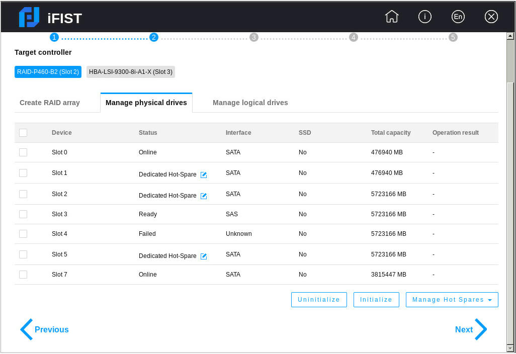
2. If a PMC controller is used, select one or more physical drives and perform the following tasks as needed:
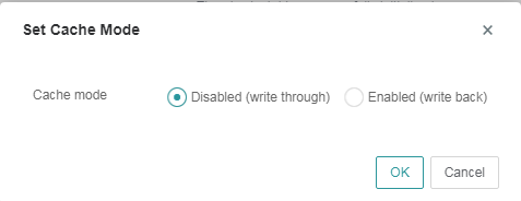
¡ Click Set cache mode to set the cache mode for the drives. In the Set Cache Mode window shown in Figure 11, select Disabled (write through) or Enabled (write back), and click OK.
The Set cache mode option is available only when the following conditions are met:
- A PMC controller (except a PMC HBA or UN-RAID-P460-M4 RAID controller) is used.
- On the Configure basic settings page, the Global write cache parameter is set to Drive specific.
Figure 11 Set Cache Mode window
¡ Click Unintialize to uninitialize the drives.
¡ Click Initialize to initialize the drives.
3. If an LSI controller is used, you can perform the following tasks:
¡ Select drives and then click Set JBOD State to set the state of the selected drives to JBOD
The Set JBOD State button is available only when the LSI controller is in RAID mode and the JBOD attribute is ON.
¡ Select drives and then click Set state to set the state of the physical drives to Unconfigured Good in the following scenarios:
- The LSI controller is in RAID mode and the JBOD attribute is ON, and the state of the physical drives is Unconfigured Bad, Unconfigured Bad-F, or JBOD.
- The LSI controller is in RAID mode and the JBOD attribute is OFF, and the state of the physical drives is Unconfigured Bad or Unconfigured Good-F.
Parameters
Parameters on the Manage physical drives tab:
· Device—Screen-printed slot number or device ID of the physical drive.
· Status—State of the physical drive.
If a PMC controller is used, the physical drive states include:
¡ Online—The physical drive is already used to build a RAID array.
¡ Ready—The physical drive is initialized and can be used to build RAID arrays.
¡ Raw—The physical drive is a raw drive and must be initialized before it can be used to build a RAID array.
¡ Failed—The physical drive is faulty.
If an LSI controller is used, the physical drive states include:
¡ Online—The physical drive is already used to build a RAID array.
¡ Offline—The physical drive is offline.
¡ Unconfigured Good—The physical drive can be used to build a RAID array.
¡ Unconfigured Bad—The physical drive is faulty.
¡ Ready—The physical drive can be used to build RAID arrays.
¡ Optimal—The physical drive is already used to build a RAID array.
¡ Failed—The physical drive is faulty.
¡ Dedicated Hot-Spare—The physical drive is configured as a hot spare of the Dedicated Hot-Spare type. A hot spare of this type can be a member of multiple logical disks at the same time, and a logical drive can have multiple hot spare members of this type.
¡ Auto Replace Hot-Spare—The physical drive is configured as a hot spare of the Auto Replace Hot-Spare type. A hot spare of this type cannot be a member of multiple logical disks at the same time, and a logical drive can have multiple hot spare members of this type.
¡ JBOD—The physical drive is a straight through drive and can be used in the operating system even if no RAID array is built.
¡ Unconfigured Good (Foreign)—The physical drive has residual RAID information. After you clear residual RAID information, the physical drive state changes to Unconfigured Good.
· Operation result—Result of the most recent operation performed on the physical drive.
· Set cache mode—Allows you to set the cache mode for the selected drives.
· Initialize—Allows you to initialize the selected drives.
A physical drive in Raw state must be initialized before it can be used to build a RAID array.
Initializing a physical drive erases all data on the drive and sets apart a small section of space on the drive for storing RAID data.
· Uninitialize—Allows you to uninitialize the selected drives.
Uninitializing a physical drive erases all data including metadata on the drive, removes the reserved space section and the system partition, and restores the drive to Raw state.
· Create Hot Spare—Allows you to create hot spares. This feature is available only for the RAID-P460-B2 storage controller.
¡ You can create hot spares of Dedicated Hot-Spare and Auto Replace Hot-Spare types.
¡ A hot spare must be a SATA or SAS drive. Make sure the capacity of the selected physical drives is equal to or greater than the minimum capacity of the existing member drives. The selected drives must also have the same interface and SSD attributes with the member drives.
¡ A logical drive with RAID 0 does not support setting hot spares.
¡ A physical drive for hot spare creation must be in Ready state.
· Clear Hot Spare—Clear hot spare configuration from the selected drives in Dedicated Hot-Spare and Auto Replace Hot-Spare states. After clearance, the selected drives will restore to the Ready state.
This feature is available only for the RAID-P460-B2 storage controller.
· Associate Logical Disks—Associate physical drives in Dedicated Hot-Spare state that are hot spare members of logical drives with other logical drives. These physical drives will also act as hot spare members for these newly associated logical drives.
This feature is available only for the RAID-P460-B2 storage controller.
Parameters on the Set Cache Mode window:
· Cache mode—Select a cache mode. Options are:
¡ Disabled (write through)—New data is written to the cache and the physical drive at the same time. Writing data will experience latency as the data need to be written to two places.
¡ Enabled (write back)—New data is written only to the cache. The data is written to the physical drive only when it needs to be replaced and removed from the cache. This mode boasts low latency but entails data loss risks because a power failure might prevent the data from being written to the physical drive.
Managing logical drives
1. On the Configure RAID arrays page, click the Manage logical drives tab.
Figure 12 Manage logical drives tab
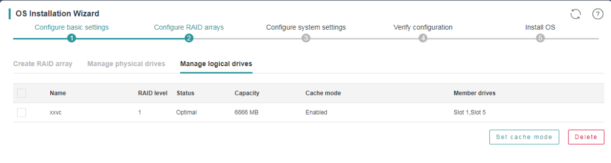
2. To set the cache mode for a logical drive:
a. Select the logical drive.
b. Click Set cache mode.
c. In the Set Cache Mode window that opens, select a cache mode and click OK.
Figure 13 Set Cache Mode window for an LSI RAID controller
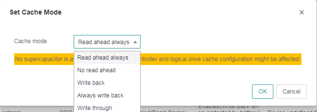
Figure 14 Set Cache Mode window for a PMC RAID controller
3. Click Next.
Parameters
· Name—Name of the logical drive.
· RAID level—RAID level of the logical drive. For more information about RAID levels, see the RAID arrays and fault tolerance chapter in H3C Servers Storage Controller User Guide.
· Status—State of the logical drive.
· Capacity—Capacity of the logical drive.
· Cache mode—Cache mode of the logical drive.
· Member drives—Physical drives used to create the logical drive.
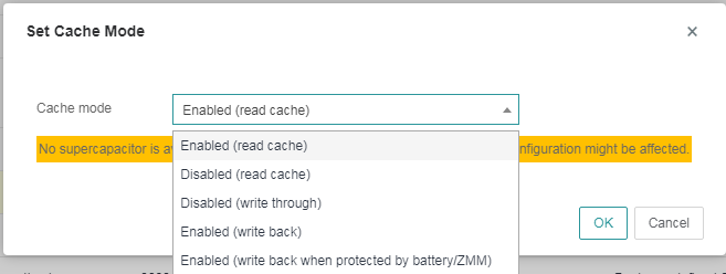
· Set cache mode—Allows you to set the read and write policies for the selected logical drives. A supercapacitor must be available to power the cache module in case of power failures to ensure data integrity. This option is available only when the RAID controller supports power fail safeguard.
Supported read and write policies are:
¡ Read ahead always/Enabled (read cache)—Always use the read-ahead policy. When retrieving data from the logical drive, the system also retrieves subsequent data and saves the subsequent data to the cache. Then, the subsequent data can be retrieved from the cache directly when requested. The read-ahead policy reduces the hard drive seek time and improves data retrieval efficiency. To use this policy, make sure the RAID controller supports power fail safeguard. This policy entails data security risks because data loss might occur in case of supercapacitor exceptions.
¡ No read ahead/Disabled (read cache)—Use the no-read-ahead policy. The system starts to retrieve data from the logical drive only when the data read request is received by the RAID controller.
¡ Write back/Enabled (write back when protected by battery/ZMM)—Use the write-back policy. If the RAID controller has a functional BBU present, data is written first to the controller cache before being written to the drive. If the RAID controller does not have a functional BBU present, write-through is resumed and data is written directly to the drive.
¡ Always write back/Enabled (write back)—Use the always-write-back policy. The controller sends a write-request completion signal as soon as the data is in the controller cache but has not yet been written to the drive. This policy improves write efficiency but requires that the RAID controller support power fail safeguard. This policy entails data security risks because data loss might occur in cases of supercapacitor exceptions.
¡ Write through/Disabled (write through)—Use the write-through policy. The controller writes data to the drive directly without first writing the data to the cache. It sends a write-request completion signal only after the data is written to the drive. This policy does not require that the RAID controller support power fail safeguard and does not entail data loss risks in the event of supercapacitor exceptions. However, the write efficiency is relatively low.
· Delete—Allows you to delete the selected logical drives.
Configuring system settings
The configuration parameters in this task vary by the operating system to be installed.
Procedure
1. On the Configure system settings page, configure the operating system-specific parameters as follows:
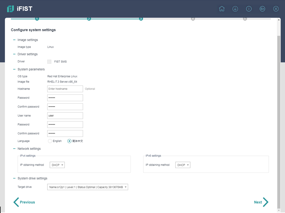
¡ For a Linux operating system, specify the hostname (optional), root password, username, user password, language, and network settings, as shown in Figure 15.
Figure 15 Setting the parameters for installing a Linux operating system
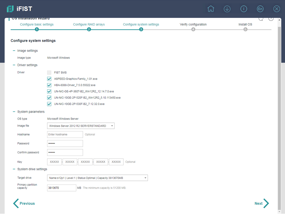
¡ For a Microsoft Windows operating system, select the drivers to install, set the image file, hostname (optional), password (optional), key (optional), and primary partition capacity, as shown in Figure 16. The available drivers include all iFIST built-in drivers listed in Table 2.
Figure 16 Setting the parameters for installing a Windows operating system
¡ For a VMware ESXi operating system, set the hostname (optional), root password, and network settings, as shown in Figure 17.
Figure 17 Setting the parameters for installing a VMware ESXi operating system
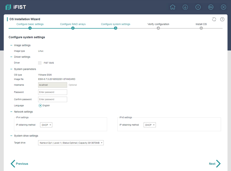
2. In the Target drive field, select the drive where you want to install the operating system.
This parameter is required for all operating systems.
3. Click Next.
Parameters
· Image type—Type of the OS image mounted to the server. Only Microsoft Windows and Linux are supported.
· Driver—List of drivers and FIST SMS, which can be selected for installation.
With a REPO file mounted to the server for OS installation, iFIST displays the drivers in the file that can be installed together with the OS if the following conditions are met:
¡ The REPO file matches the server cards.
¡ The OS in the file is not a VMware ESXi system.
· OS type—Operating system type of the mounted image. Supported operating system types include:
¡ Red Hat Enterprise Linux.
¡ SuSE Linux Enterprise Server.
¡ CentOS.
¡ VMware ESXi.
¡ Ubuntu Server.
¡ CAS.
¡ Oracle Linux.
¡ Microsoft Windows Server.
· Image file—Image file of the operating system to be installed.
· Hostname—Specify the hostname of the server. If you do not specify a hostname for a Windows operating system, an automatically assigned hostname is used. If you do not specify a hostname for a Linux operating system, localhost is used. When IPv4 settings are configured as DHCP for the VMware ESXi system, the hostname cannot be configured.
· Password—If a Windows operating system is to be installed, enter the password used to log in to the operating system. If a Linux operating is to be installed, enter the Linux root password.
· User name—This parameter is available only when a Linux operating system is to be installed. Enter the user name used to log in to the operating system. The VMware ESXi and CAS operating systems do not support configuring the user name.
· User password—This parameter is available only when a Linux operating system is to be installed. Enter the user login password. The VMware ESXi and CAS operating systems do not support configuring the user password.
· Language—Select the language used in the operating system. This parameter is available only when a Linux operating system is to be installed. The VMware ESXi and CAS operating systems use English by default, which cannot be modified.
· Platform language—This parameter is available only when a CAS system is to be installed. Select the language used in the CAS platform. Options are Simplified Chinese and English.
· Network settings—This area is available only when a Linux operating system is to be installed. Select an IP address obtaining method in the IPv4 settings and IPv6 settings subareas separately. Options are:
¡ DHCP—Obtains an IPv4 or IPv6 address through DHCP.
¡ Static—Uses a manually configured IPv4 or IPv6 address. If this method is used, you must manually configure the following parameters:
- IPv4 address, subnet mask, and optionally the default gateway address in the IPv4 settings area.
- IPv6 address, subnet prefix length, and the default gateway address in the IPv6 settings area.
The following guidelines apply when you configure the network settings:
¡ For the CAS operating system:
- In the IPv4 settings area, the DHCP option is not available.
- The default gateway address and the IPv4 address specified in the IPv4 settings area must reside on the same network segment.
- The IPv6 settings area is not available.
¡ For the VMware ESXi operating system:
- The default gateway address and the IPv4 address specified in the IPv4 settings area must reside on the same network segment.
- The Static option in the IPv6 settings area is not available. The IPv6 address obtaining method can only be DHCP.
¡ For the Ubuntu Server operating system:
- The default gateway address and the IPv4 address specified in the IPv4 settings area must reside on the same network segment.
- If you select Static in the IPv4 settings area, the IPv6 settings area becomes unavailable. If you select Static in the IPv6 settings area, the IPv4 settings area becomes unavailable.
· Key—This parameter is available only when a Windows operating system is to be installed. Enter the key required for operating system installation.
· Target controller—Select the storage controller where the operating system is to be installed. This parameter is available only when the server has multiple storage controllers installed.
· Target drive—Select the drive where the operating system is to be installed.
· Primary partition capacity—This parameter is available only when a Windows operating system is to be installed. Specify the capacity of the primary partition. A minimum capacity of 50 GB is required for operating system installation. When the server has a large physical memory, set the primary partition capacity to the maximum value as a best practice.
If a Linux operating system is to be installed, the maximum capacity of the target drive is used as the primary partition capacity by default and cannot be changed. The minimum primary partition capacity required for Linux operating system installation is 80 GB.
Verifying the configuration
Procedure
1. On the Verify configuration page, verify that the operating system installation settings are correct.
Figure 18 Verifying the configuration
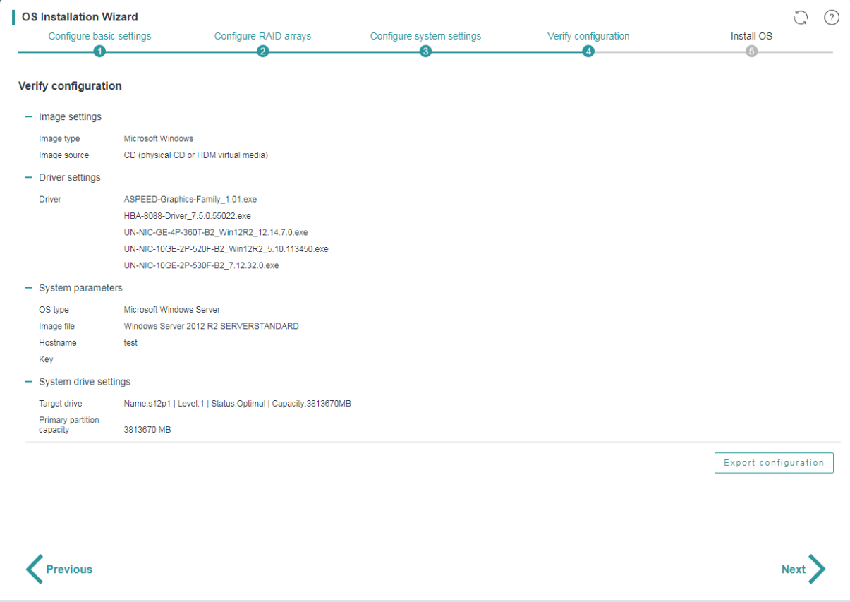
2. To revise the settings, click Previous. If no revision is required, click Next.
3. To export the RAID and operating system installation settings to a file:
a. Click Export configuration.
b. Select the storage device where you want to store the exported file and set the exported file format (xml or img).
The exported file is MD5-encrypted to prevent file tampering.
c. Click OK.
You can import the configuration file into another server on the Configure basic settings page.
For a server configured with multiple storage controllers, you might export the configuration file of the server successfully if no OS is installed in the storage controllers.
The configuration file must be exported to a USB flash drive formatted with the FAT32 or NTFS file system.
|
|
NOTE: In iFIST-1.35 or earlier, the configuration file is exported to the root directory of the USB flash drive. In iFIST-1.36 or later, the configuration file is exported to the /iFIST/OsInstall directory of the USB flash drive. |
Triggering automated operating system installation
Restrictions and guidelines
Do not remove the boot media before the OS installation is complete.
After the OS installation is complete, install the related drivers as soon as possible to ensure correct operation of the operating system.
The server might automatically restart multiple times during installation of a Windows operating system.
After an OS is installed, the first boot option changes to HDD. You can log in to HDM or enter the BIOS setup utility to modify system boot options. For more information, see H3C Servers HDM User Guide and H3C Servers User Guide.
Procedure
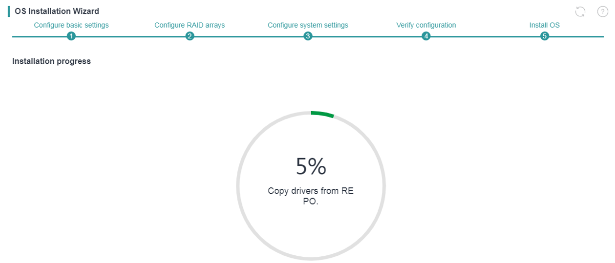
After you click Next on the Verify configuration page, iFIST starts to prepare the server for the OS installation and displays the real-time progress, as shown in Figure 19.
After the preparation is complete, iFIST reboots the server and installs the operating system.
The server is automatically restarted after the OS installation is complete without manual intervention.
Figure 19 Installing the operating system on the server
Intelligent diagnostics
Server diagnostics
Server Diagnostics scans the server modules to collect statistics for module-based performance and health diagnosis. It facilitates server troubleshooting and reduces the risks of unexpected problems during server usage.
Server Diagnostics supports diagnosing various modules on a server, including the BIOS, CPU, memory, hard disks, storage controllers, logical drives, network adapters, GPUs, other PCIe devices, PSUs, fans, and temperature.
Restrictions and guidelines
If the server uses HDM of a version earlier than version 1.30.08, iFIST cannot detect or diagnose the BIOS, PSU, fan, or temperature modules on the server. This restriction does not apply if the server uses HDM-1.30.08 or a later version.
In iFIST-1.41 and later, to view feature diagrams for this function or give feedback, you can scan the QR code on the screen with your mobile device.
The Server diagnostics feature is available only on the following server models:
· H3C UniServer B5700 G3
· H3C UniServer B5800 G3
· H3C UniServer B7800 G3
· H3C UniServer R2700 G3
· H3C UniServer R2900 G3
· H3C UniServer R4700 G3
· H3C UniServer R4900 G3
· H3C UniServer R5300 G3
· H3C UniServer R6700 G3
· H3C UniServer R6900 G3
· H3C UniServer R4900 G5
Viewing server module information
Restrictions and guidelines
A server re-scanning is recommended after a server module change or a hot swapping occurs.
iFIST cannot detect modules that are unidentifiable to the operating system.
Procedure
1. On the iFIST home page, click Intelligent Diagnostics, and select Server Diagnostics.
iFIST starts to scan the server and displays the system information and server module information on the Device Info tab, as shown in Figure 20.
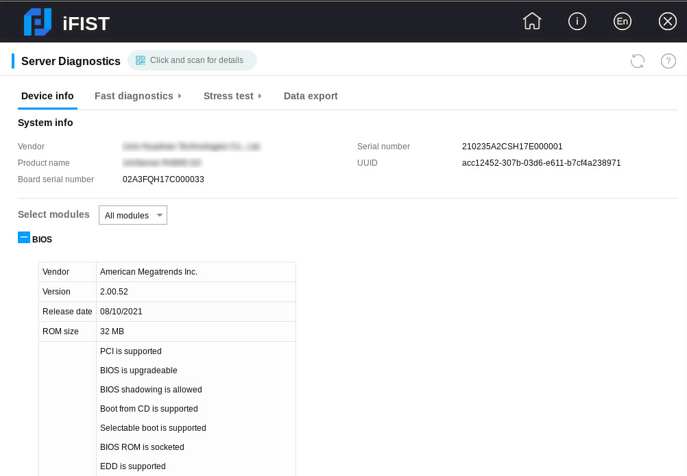
2. To view information about a specific server module, select the module from the Select modules list. By default, All modules is selected and information about all detected server modules are displayed.
iFIST displays N/A for a server module if it cannot obtain the server module information.
Parameters
· System info—Basic server information, including the server's vendor, name, serial number, UUID, and the serial number of the system board.
· Select modules—To view information about a specific module, select the module from the list.
Supported modules and the information displayed for them are as follows:
¡ BIOS—Basic information about the BIOS, including the BIOS vendor, version, release date, ROM size, and supported features.
¡ HDM—HDM information, including the firmware version, serial number, CPLD version, event count, recent events, POST result, TCP port numbers for HTTP and Telnet services, shared port address information, and dedicated port address information.
¡ CPU—CPU information including the maximum number of CPUs supported. For each detected CPU, the following information is displayed: socket ID, version, core count, enabled core count, SMBIOS structure handle, current and maximum speeds, external clock speed of the processor socket, level-1 data and instruction cache capacities, level-2 and level-3 cache capacities, stepping, and vendor ID.
¡ Memory—Memory information, including the maximum number of memory chips supported and total memory size. For each memory chip, the following information is displayed: slot number, type, vendor, DIMM description, DIMM size, memory DRAM type, serial number, speed, correctable error status, and correctable error count.
|
|
NOTE: The correctable error status and correctable error count can be displayed only when the server is installed with a CPU based on the Purley platform. |
¡ Storage—Information about storage controllers, logical drives, and physical drives.
- Storage controller—Information about the storage controller, including its slot number, model, type, operating mode, installed memory, WWN, presence of a supercapacitor, firmware version, hardware revision version, driver name, driver version, board barcode, number of connected physical drives, number of unallocated physical drives, number of logical drives, serial number, number of ports, and PCIe bus information.
- Logical drive—Information about the logical drive, including its logical index, device path, name, status, capacity, drive type, volume ID, RAID level, stripe size, number of physical drives, number of offline physical drives, and slot number of the connected storage controller.
- Physical drive—Information about the physical drive, including its vendor, device path, WWN, controller type, drive type, sector size, current, maximum, and threshold temperatures, capacity, SSD, firmware version, model, serial number, negotiated link speed, spindle speed, and slot number of the connected storage controller.
¡ NIC—Network adapter information, including the product name, slot number, driver name, driver version, board barcode, PCIe bus information, vendor ID, device ID, subsystem device ID, and subsystem vendor ID.
¡ GPU—GPU information, including the product name, slot number, PCIe bus information, revision version, driver name, driver version, board barcode, cache capacity, device ID, vendor ID, subsystem device ID, and subsystem vendor ID.
¡ PCIe device—PCIe module information, including the product name, slot number, PCIe bus information, driver name, driver version, board barcode, device ID, vendor ID, subsystem device ID, and subsystem vendor ID.
¡ PSU—Power supply information, including the number of supported PSUs, slot number, presence status, serial number, firmware version, and the maximum power. iFIST cannot display PSU information for a blade server.
¡ Fan—Fan information, including the number of supported fans, slot number, presence status, rotating speed, rate ratio, and redundant status. iFIST cannot display fan information for a blade server.
¡ Temperature—Temperature information, including the sensor name, current temperature, unit, temperature status, lower and upper critical thresholds, lower and upper warning thresholds, and lower and upper caution thresholds.
Performing fast diagnostics
About this task
This function allows you to perform all-round operational and health status checks on selected server modules. It provides instructions for you to troubleshoot and fix the faults, if any, detected in the diagnosis process.
iFIST lists all the server modules it can diagnose in the Please select the components to diagnose area of the Server Diagnostics page. You can select the modules to diagnose as needed.
Restrictions and guidelines
Do not power off a server while fast diagnostics is in progress because doing so might cause the server modules to malfunction.
If the server uses the UEFI boot mode and has NVMe SSD expander modules installed, perform the following steps before you run the system diagnostic checks on the server:
1. Access the BIOS setup page.
2. Select Socket Configuration > IIO Configuration > Intel® VMD technology.
3. Set the Intel@ VMD for Volume Management Device for Pstack1 attribute to Disabled for the CPUs connected to the NVMe SSD expander modules.
DCPMMs do not support fast diagnostics.
Procedure
1. On the iFIST home page, click Intelligent Diagnostics, and select Server Diagnostics.
iFIST starts to scan the server and displays the system information and server module information on the Device Info tab.
2. Select Fast diagnostics > Select configuration.
The Select configuration tab opens, as shown in Figure 21.
For descriptions of the parameters on this tab, see "Parameters."
Figure 21 Select configuration tab
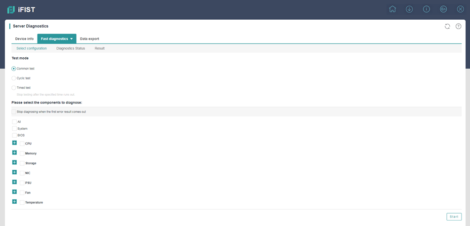
3. Select the Stop diagnosing when the first error result comes out option as needed.
4. Select the test mode. Options are Common test, Cyclic test, and Timed test.
¡ To use the cyclic test mode, set the number of test cycles in the Cycles field.
¡ To use the timed test mode, set the test duration in minutes in the Time field.
5. Select the modules to test.
Only the selected modules will be tested in the fast diagnostics process.
6. Click Start.
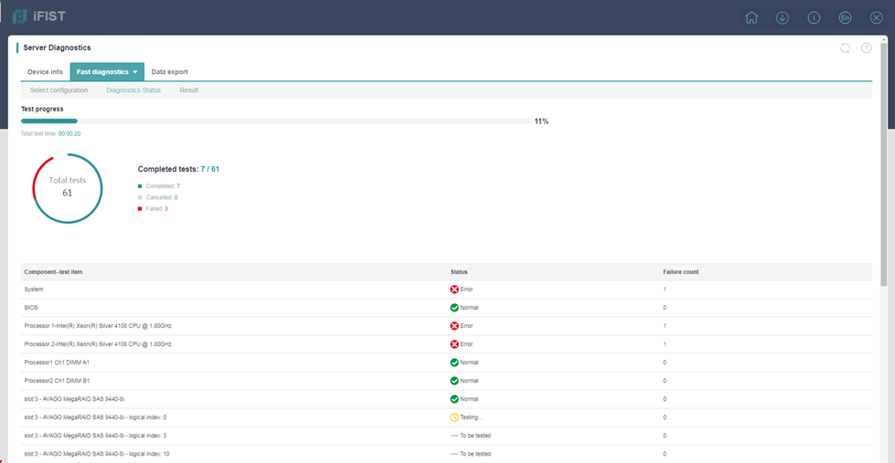
iFIST opens the Diagnostic status page upon start of the diagnostic process, as shown in Figure 22. The page provides information about the ongoing diagnostic tests, including the test progress, summarized test statistics, and module-specific test results.
Figure 22 Diagnostic status page
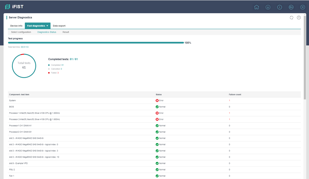
7. After the fast diagnostic process is completed, click Result to view the diagnostic results.
The Result tab displays the test result for each component, and provides the failure reason and recommended fixes if the test result is Error, as shown in Figure 23.
Figure 23 Result tab
Parameters
· Parameters in the Test mode area:
¡ Common test—A common test tests the selected modules sequentially until the last module is tested.
¡ Cyclic test—A cyclic test tests the selected modules repeatedly for the specified test cycles. In each test cycle, all the selected modules are tested sequentially.
¡ Timed test—A timed test completes after it has run for the specified time period.
· Parameters in the Please select the components to diagnose area:
¡ All—Checks all the detected server modules.
¡ BIOS—Checks the firmware version of the BIOS.
¡ System—Checks the serial number, health state, and PCIe link state of the server. Only H3C UniServer R6900 G3 servers support the PCIe link state check.
¡ CPU—Checks the number of CPUs on the server, runs UPI and floating-point tests on the CPUs, and checks for MCE errors.
¡ Memory—Determines if the number of memory chips on the server meets the server requirements.
¡ Storage—Runs the following tests on storage modules:
- Bandwidth, rate, health, and capacitance status tests on storage controllers.
- Hard disk self-test.
- Read-write tests on logical drives.
¡ NIC—Runs the following tests:
- NIC bandwidth and rate tests to determine if they are below the nominal values.
- MAC address conflict test.
- Network port self-test.
¡ PCIe—Determines if the bandwidth and speed of the PCIe device meet the server requirements.
¡ GPU—Checks whether the GPU's bandwidth is below the nominal value.
¡ PSU—Checks the status of PSUs on the serve. Displaying of this field depends on server model.
¡ Fan—Checks the health status of fans on the server. Displaying of this field depends on server model.
¡ Temperature—Checks the temperature sensor status of server modules, including memory, CPU, PSU, storage controller, and PCIe slot.
¡ MCA—Checks for machine check architecture (MCA) errors.
Performing stress tests
About this task
This function allows you to run stress tests on selected server components. The test results show the detected problems and optionally the recommended actions to fix the problems.
Procedure
1. On the iFIST home page, click Intelligent Diagnostics, and select Server Diagnostics.
iFIST starts to scan the server and displays the system information and server component information on the Device Info tab.
2. Select Stress test > Select configuration.
Figure 24 Configuring stress test settings
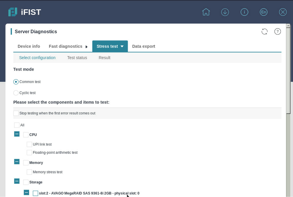
3. Select the Stop testing when the first error result comes out option as needed.
4. Select the test mode. Options are Common test and Cyclic test.
To use the cyclic test mode, set the number of test cycles in the Cycles field.
5. Select the tests you want to run for each component. Options are:
¡ All—Select this option to run all the tests listed in this area.
¡ CPU—Select the tests you want to run for each processor. Options are:
- UPI link test—Tests the transmission capability and transmission rate of Ultra Path Interconnect (UPI) and QuickPath Interconnect (QPI) links.
- Floating-point arithmetic test—Tests the floating-point arithmetic function of the processor.
¡ Memory—Select Memory stress test to run the memory stress test and check for memory-related MCA memory errors. DCPMMs do not support stress tests.
¡ Storage—Select the tests to run on each physical drive and logical drive. Options are:
- Read test—Tests whether the drive can correctly process sequential read requests.
- Rand Read test—Tests whether the drive can correctly process random read requests
¡ NIC—Select External loopback test to run the external loopback test on the NIC. The external loopback test allows you to test whether the selected NIC ports can send and receive packets correctly. Depending on the type of the NIC ports and their cabling state, the following test modes are supported:
- Single-Port Self-Loop—Available only for fiber ports. To run the single-port self-loop test on a fiber port, connect the sending and receiving ends of the port through the optical fiber, and then drag the port to the single-port self-loop box.
- Dual-Port Pairing—To run the dual-port pairing loopback test on pairs of interconnected NIC ports, drag the port pairs to the dual-port pairing box.
Only the H3C UniServer R6900 G3 servers support this feature.
¡ MCA—Select MCA test to check for machine check architecture (MCA) errors.
6. Click Start.
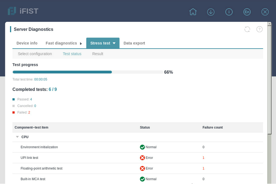
The Test status page opens, displaying information about the ongoing stress tests.
Figure 25 Test status
7. To abort the testing process, click Cancel.
8. After the selected stress tests are completed, click Restart to run the tests again, if needed.
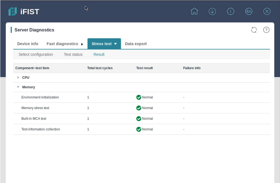
9. To view the test results, click Result.
Figure 26 Test result
Exporting data
About this task
You can export the server module information, server diagnostics data, and operation log data to a USB flash drive for further analysis.
Restrictions and guidelines
Before the export, insert the USB flash drive to the server and format it by using the FAT32 file system.
Procedure
1. Click Intelligent Diagnostics, and select Server Diagnostics.
2. Click the Data export tab.
The Data Export tab opens, as shown in Figure 27.
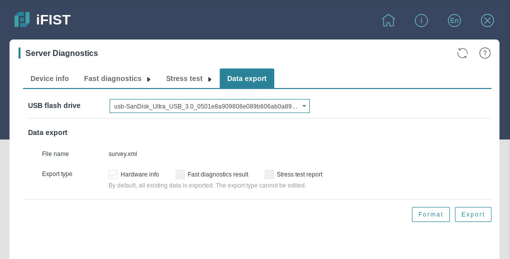
3. From the USB flash drive list, select the USB flash drive to which you want to export the server diagnostics data, and then click Format to format it by using the FAT32 file system.
Format the USB flash drive with caution. This operation deletes data in the USB flash drive.
4. Click Export.
Memory smart-test
The memory smart-test feature tests the memory in the POST memory initialization stage through the memory test tool embedded in the BIOS. In the current software version, only the Hynix, Samsung, and Micron memory chips are supported. After the test, you can view the test result on the iFIST.
|
|
NOTE: · This feature can perform tests only in UEFI boot mode. · The memory test feature is supported only when all memory chips on the server are from a single vendor, Hynix, Samsung, or Micron. · Only some servers and BIOSs of the specific versions support the memory test feature. For more information, see the iFIST usage guidelines. |
Select diagnostics test
Restrictions and guidelines
Select the test and repair policy with caution. If you perform a test after repairing, no errors can be tested.
After the test is started, do not manually reboot the server. The server will be automatically rebooted by the diagnostics test program.
Procedure
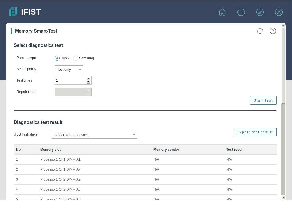
1. Click Intelligent Diagnostics, and select Memory Smart-Test to enter the page as shown in Figure 28.
2. Configure the test parameters.
3. Click Start test. The diagnostics test will start after the server is cold rebooted.
Parameters
· Parsing type—In the current software version, the diagnostics test supports testing only Hynix, Samsung, and Micron memory chips.
· Select policy—Options include Test only and Test and repair.
· Test times—Number of smart-test polling times for the memory chips. More polling times mean a longer test time.
¡ Only Hynix and Samsung memory chips support this field.
¡ For Hynix memory chips, the value range is 1 to 5.
· Repaired errors for single DIMM—Maximum number of repaired errors for a single memory chip when the policy is test and repair.
¡ When the server is installed with BIOS firmware of version BIOS-2.00.34 or later, Hynix memory chips support this field, and the value range is 1 to 10.
¡ When the server is installed with BIOS firmware of version BIOS-2.00.41 or later, Samsung memory chips support this field, and the value range is 0 to 32.
¡ When the server is installed with BIOS firmware of version BIOS-2.00.43 or later, Micron memory chips support this field, and the value range is 1 to 4.
· Test mode—Options include Normal mode and Enhanced mode. The default is Enhanced mode.
¡ Only Samsung and Micron memory chips support this field.
¡ When the server is installed with BIOS firmware of a version earlier than BIOS-2.00.37, Samsung memory chips support only the enhanced mode.
¡ When the server is installed with BIOS firmware of version BIOS-2.00.47 or later, Micron memory chips support this field.
· Keep diagnostics enabled—You can enable or disable this feature. By default, the memory smart-test feature is restored to disabled state after the diagnostics test is finished. Only Micro memory chips support this field.
· Repaired errors for each socket (each CPU)—Maximum number of repaired errors for a single socket when the policy is test and repair.
¡ Only Micro memory chips support this field.
¡ The value range is 1 to 48.
View and export the diagnostics test result
|
|
IMPORTANT: In the current software version, the diagnostics test result can be exported to a USB flash drive formatted by using the FAT32 or NTFS file system. |
Procedure
1. Click Server Diagnostics, and select Memory Smart-Test.
2. View the diagnostics test result on the page as shown in Figure 29.
Figure 29 Diagnostics test result
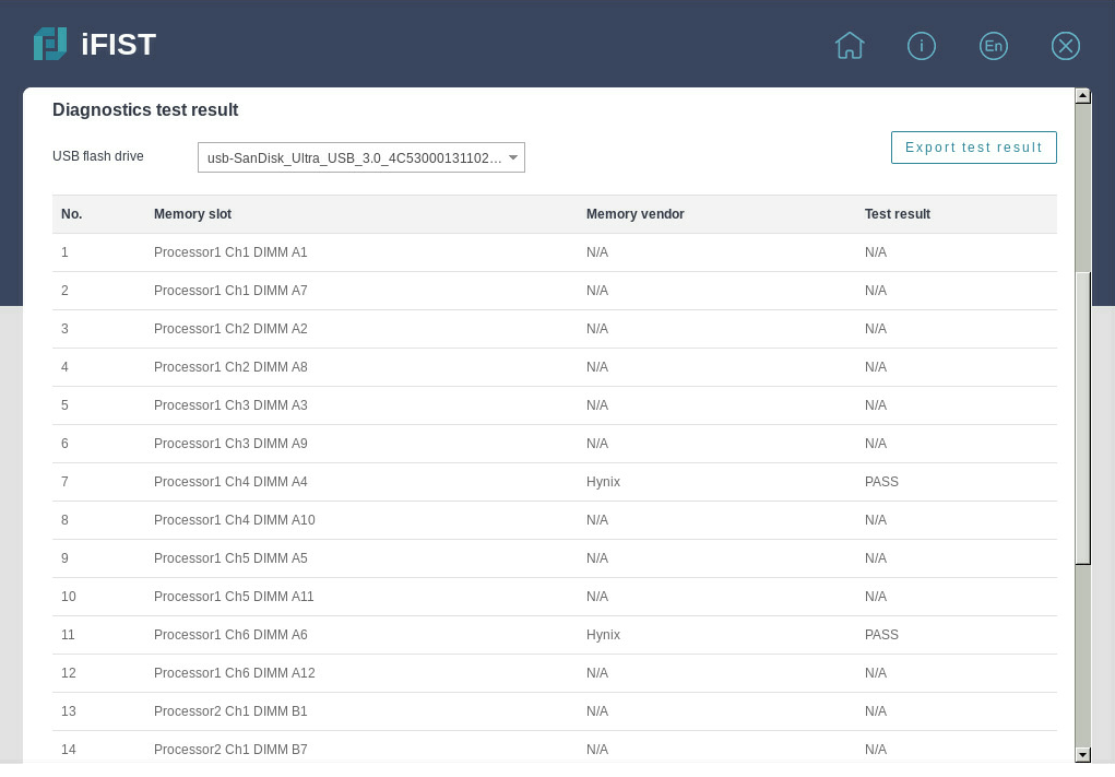
3. Select a storage device, and click Export test result to download the test result to the iFIST/SmartTest directory in the root directory of the USB flash drive.
Parameters
· Memory slot—Slot number of the memory chip.
· Memory vendor—Vendor of the memory chip. This field displays N/A when the memory is absent.
· Test result—Result of the smart-test, as shown in Table 4, Table 5, and Table 6. This field displays N/A when the test is not finished, the memory chip is corrupted, or the memory chip is absent.
|
Test result |
Remarks |
|
Training Failure |
Memory training failed. |
|
Pass |
The memory passed the test. |
|
Fail (PPR Disable) |
Errors occurred to the memory chip. |
|
Fail (PPR Pass) |
Errors occurred to the memory chip, and the memory chip was repaired successfully. |
|
Fail (PPR Fail) |
Errors occurred to the memory chip, and the memory chip failed to be repaired. |
|
Temp. Overflow |
The memory chip temperature was too high, and the memory test was skipped. |
|
Error Overflow |
Errors overflew, and the total number of errors exceeded the maximum number of errors supported (a single DIMM can repair up to 32 errors) . |
|
Test result |
Remarks |
|
Pass |
The memory passed the test. |
|
Fail |
Errors occurred to the memory chip. |
|
Non-fixable Fail |
Errors overflew, and the total number of errors exceeded the maximum number of errors supported (a single DIMM can repair up to 10 errors) . |
|
SKIP |
Memory training failed, or the current memory chip is not a Hynix one. |
|
REPAIRED |
Errors occurred to the memory chip, and the memory chip was repaired successfully. |
|
Test result |
Remarks |
|
No issues found |
Memory training failed or the memory passed the test |
|
PPR Disabled |
Errors occurred to the memory chip, and only the test was performed |
|
PPR Success |
Errors occurred to the memory chip, and the memory chip was repaired successfully |
|
PPR Failure |
Errors occurred to the memory chip, and the memory chip failed to be repaired |
|
PPR Inprogress |
Errors occurred to the memory chip, the repair function was not started, and the memory chip was to be repaired. |
|
PPR Limit Exceeded |
Errors overflew, and the total number of errors exceeded the maximum number of errors supported (a single DIMM can repair up to 4 errors, and a single socket can repair up to 48 errors) |
|
DIMM Configuration not supported |
The memory chip does not support this test. |
Configuration management
Use this function to perform the following tasks:
· Import configuration—Import the HDM, BIOS, or RAID configuration file in a USB flash drive to the system to overwrite the existing configuration.
· Export configuration—Export the current HDM, BIOS, or RAID configuration, generate a configuration file, and save it in the iFIST/ConfManage directory in the root directory of the USB flash drive.
· ACS configuration—Configure ACS capability and ACS control.
|
|
NOTE: · In the current software version, only USB flash drives formatted by using the FAT32 or NTFS file system support importing and exporting configurations. · The PMC storage controller does not support importing or exporting RAID configuration. · The configuration management function needs to cooperate with HDM software. Only HDM-1.11.25 and later support configuration management. · Support for ACS configuration varies by device model. For more information, see the GUI. · To configure ACS capability, you must use the HDM software. For more information, see the iFIST release notes. · To configure ACS control, you must use the BIOS software. For more information, see the iFIST release notes. |
Import configuration
Restrictions and guidelines
· Before importing RAID and BIOS configurations, make sure the device model and component configuration (for example, storage controller model, disk count, and slots) are the same. When importing RAID configuration, make sure the storage controller operates in RAID mode.
· Before importing HDM configuration, make sure the device model is the same. First delete the comment statements for the user configuration information in the configuration file, and then modify the user password into a plaintext password.
· To import configuration successfully, make sure the bonding mode in the configuration file is the same as the bonding mode of the device before importing HDM configuration.
· Before importing the RAID configuration, if the old RAID information of the disks is not cleared, the RAID configuration will be marked as foreign configuration. As a result, the RAID configuration will fail. Please first clear the RAID configuration of the disks in the BIOS.
· Before importing HDM configuration, if a configuration item is deleted or does not exist in the configuration file, the configuration item remains as it was after the configuration is imported.
· Modify the configuration file with caution, and make sure the configuration information after modification is valid. Otherwise, the configuration file might fail to be imported.
· After the HDM configuration is imported successfully, HDM might automatically restart to make the configuration take effect.
· After the BIOS configuration is imported successfully, you must restart the server to make the configuration take effect.
· After the RAID configuration is imported successfully, the configuration takes effect about 40 seconds later.
· During the configuration import process, do not power off the server. Otherwise, some functions of iFIST might fail.
· When you import HDM, BIOS, or RAID configuration, if the Web interface prompts that an entry fails to be imported, the import is paused. In this case, you must modify the entry that fails to be imported, and import the configuration again. Repeat this step until the import is finished.
· The imported RAID configuration does not contain configuration of the RAID controller itself (for example, RAID controller mode).
· To ensure successful configuration import, do not perform any configuration management operations on the HDM Web interface during the configuration import process.
Procedure
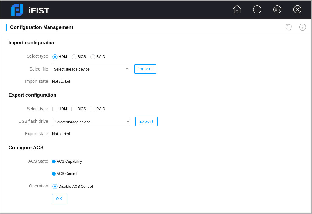
1. Click Configuration Management to enter the configuration management page.
2. Select the type of the configuration to be imported.
3. Select a storage device, and then select a configuration file in the storage device, as shown in Figure 30.
Figure 30 Importing configuration

4. Click Import.
Export configuration
Restrictions and guidelines
· Before exporting RAID configuration, make sure the storage controller has been initialized.
· Before exporting RAID configuration, make sure logical drives of the RAID controller are in normal state, and no scaling, migration, rebuilding, or erasing operations are performed.
· The exported RAID configuration does not contain configuration of the RAID controller itself (for example, RAID controller mode).
· To export configuration successfully, do not perform any configuration management operations on the HDM Web interface during the configuration export process.
Procedure
1. Click Configuration Management to enter the configuration management page.
2. Select one or multiple types of configuration to be exported, as shown in Figure 31.
Figure 31 Exporting configuration

3. Select a storage device, and click Export to start exporting the configuration.
4. After the configuration export is completed, you can view the export result in the dialog box that opens.
Configure ACS
Restrictions and guidelines
· Before configuring ACS, make sure all PCIe switch cards are in place.
· You cannot disable the ACS capability attribute.
Procedure
1. Click the Configuration Management icon to enter the configuration management page.
2. Select an operation. In the dialog box that opens, click OK. The selected operation takes effect after the server is cold rebooted.
Figure 32 Configuring ACS
3. When the ACS capability attribute is not enabled, you can enable only ACS capability or enable both ACS capability and ACS control.
4. When the ACS capability attribute is enabled, you can disable the ACS control attribute if the ACS control attribute is enabled, and you can enable the ACS control attribute if the ACS control attribute is disabled or not enabled.
Download logs
Use this function to download server logs and save the logs to the iFIST/LogDownload directory of a USB flash drive inserted into the server.
Restrictions and guidelines
You can download logs to a USB flash drive formatted with the FAT32 or NTFS file system.
In the current software version, only logs of hard disks of the following vendors can be downloaded: Seagate, Hitachi, Toshiba, Samsung, Intel, Kioxia, Memblaze, and Micron.
In the current software version, the logs of Toshiba hard disks can be downloaded only when they operate in pass-through mode.
The log download function needs to cooperate with HDM software. Only HDM-1.11.19 and later support downloading SDS logs.
To download logs successfully, make sure you have not one-click collected information on the HDM Web interface before downloading logs.
Procedure
1. Click Download Logs to enter the page as shown in Figure 33.
2. Select the types of logs to download.
3. Select the target USB flash drive.
4. Click Start download.
Figure 33 Downloading logs (for example, hard disk logs)
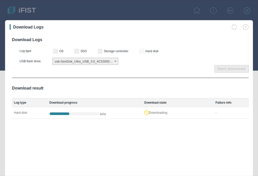
Parameters
· Log type—Type of logs to download. In the current software version, OS logs, SDS logs, storage controller logs, and hard disk logs can be downloaded.
· USB flash drive—USB flash drive to save the downloaded logs.
· Download progress—Progress of downloading a single type of logs.
· Download state—Log download state. Options are Download succeeded, Downloading, and Download failed.
· Failure info—When the storage controller logs fail to be downloaded, the failure info displays the corresponding slot number, model, and failure reason. When the hard disk logs fail to be downloaded, the failure info displays the corresponding vendor, serial number, location, and reason.
Secure data clearing
When a server stops running for the end of lifecycle or other reasons, you can use the secure data clearing function to clear the HDM, BIOS, and storage data saved in the server to avoid user data breach. If the data to be cleared is large, data clearing might take a long time (one day or longer). After iFIST starts to clear data, the other functions become unavailable. Before clearing data, first make all preparations.
|
|
CAUTION: · Use the data clearing function with caution. Before using this function, make sure the data to be cleared is useless and can be cleared. If the data to be cleared is useful, first back up it to avoid loss of important data. · Before clearing data, make sure all external storage devices (including but not limited to external hard drives) of the server have been removed to avoid clearing data by mistake. · During the data clearing process, do not reboot the server, reboot HDM, or modify the operating system configuration. |
Restrictions and guidelines
· The secure data clearing function can clear only data in physical drives that can be recognized by the operating system. If a physical drive cannot be recognized by the operating system for damage or other reasons, data in the physical drive cannot be cleared.
· To clear data of storage-related components again after you clear data of storage-related components, you must restart iFIST.
· If data in a hard drive fails to be cleared during the data clearing process, you can try to clear data in the hard drive in other methods.
Procedure
1. Click Secure Data Clearing.
Figure 34 Secure Data Clearing page
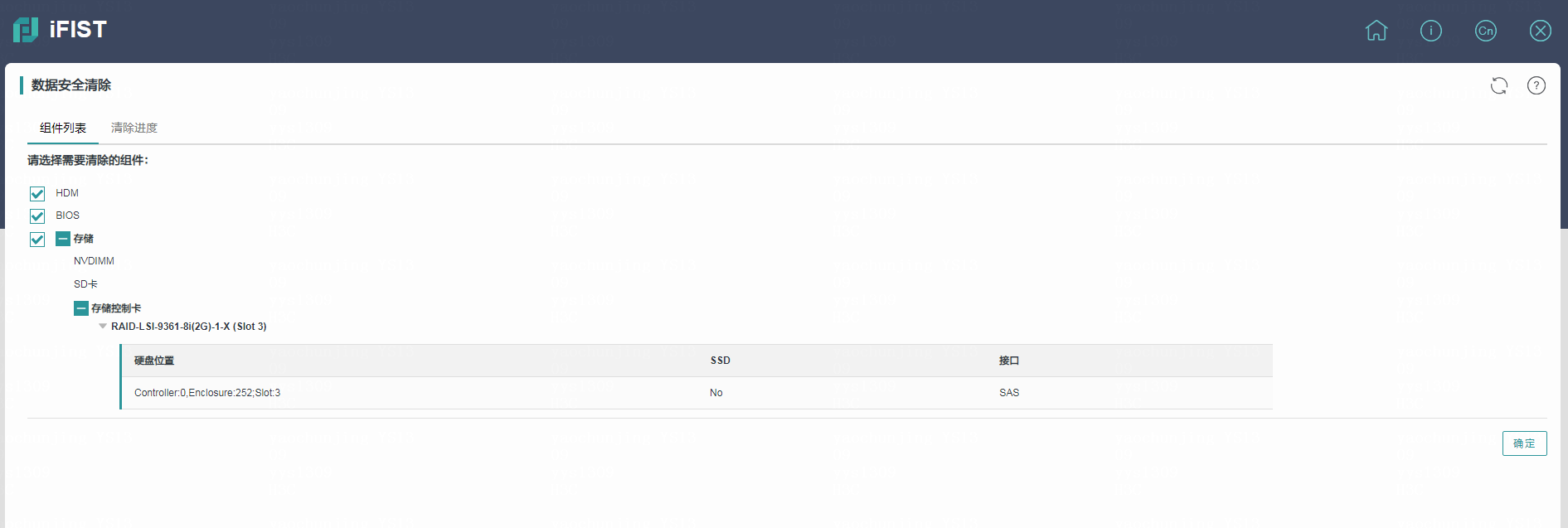
2. On the Component list tab, select the components for which you want to clear data, including HDM, BIOS, and storage. Table 7 shows the influence of the secure data clearing function on each component.
3. Click OK. In the dialog box that opens, enter the case-insensitive string YES to start clearing data. The system switches to the Clearing progress tab automatically.
4. After data clearing is finished, you can view the clearing result in the Clearing progress column, as shown in Figure 35.
Figure 35 Viewing the clearing progress
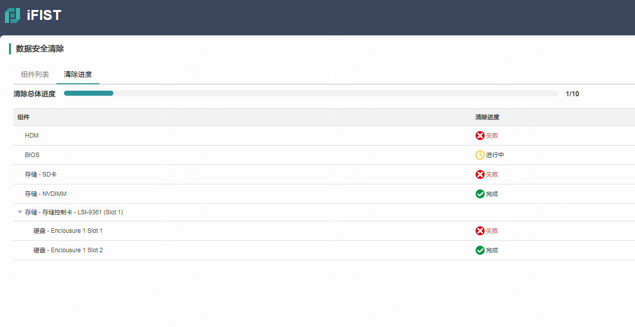
Table 7 Influence of the secure data clearing function
|
Component name |
Influence |
|
HDM |
Restore HDM to default configuration |
|
BIOS |
· Restore the BIOS to default configuration · The administrator and user passwords are cleared on the BIOS side. When the server is rebooted next time, a user whose password is cleared can enter the BIOS Setup directly without entering a password. |
|
No-volatile DRAM (NVDIMM) |
All data in non-memory mode is cleared, and the NVDIMM changes to the full memory mode. |
|
Storage controller |
· All logical drives of RSTe and VROC storage controllers are deleted. · Logical drives of the following PMC storage controllers are all deleted: ¡ HBA-H460-M1, HBA-H460-B1 ¡ RAID-P460-M2, RAID-P460-B2, RAID-P460-M4, RAID-P460-B4 ¡ RAID-P4408-Mf-8i ¡ RAID-P2404-Mf-4i · Logical drives of the following LSI storage controllers are all deleted. If an LSI storage controller is in RAID mode before the logical drives are deleted, the JBOD attribute of the RAID mode becomes ON after the logical drives are deleted. ¡ RAID-LSI-9361-8i(1G)-A1-X. ¡ RAID-LSI-9361-8i(2G)-1-X. |
|
Hard drive |
Data in all hard drives is cleared |
|
SD card |
Data in all SD cards is cleared |
Firmware update
After you mount a REPO image file through a CD (physical CD or HDM virtual media) or USB flash drive, you can use this function to update various firmware products for the server at the same time, including HDM, BIOS, various CPLDs, storage controller firmware, NIC firmware, and hard disk firmware.
|
|
NOTE: · For how to obtain a REPO image file, see the REPO Usage Guide. · In the current software version, USB flash drive partitions formatted by using the FAT32, EXT2/3/4, or NTFS file system can be used to mount a REPO image file. A REPO image file name supports only letters, digits, dots (.), hyphens (-), and underscores (_), and cannot exceed 64 characters (including the file extension). · The name of the USB flash drive path where the REPO image file resides cannot exceed 64 characters. |
Restrictions and guidelines
· You cannot switch the page when an inventorying task or deployment task is in progress. To switch the page, you must first cancel the task in progress or wait until the current task is completed. After you switch to another page, the inventorying task or deployment task information on the firmware update page will be cleared.
· After you click Stop inventorying or Stop deployment, the inventorying or deployment task will be stopped until inventorying or deployment is completed on the current firmware.
· After the firmware is updated, do not perform other operations until the new firmware takes effect. Otherwise, the functions might be abnormal.
Procedure
1. Mount a REPO image file with one of the following method:
¡ Mount the REPO image file through a CD. For more information, see "Prerequisites."
¡ Mount the REPO image file through the USB flash drive. Connect the USB flash drive where the REPO image files resides to the USB connector on the server.
2. Click Firmware Update to enter the firmware update page, as shown in Figure 36.
Figure 36 Firmware Update page
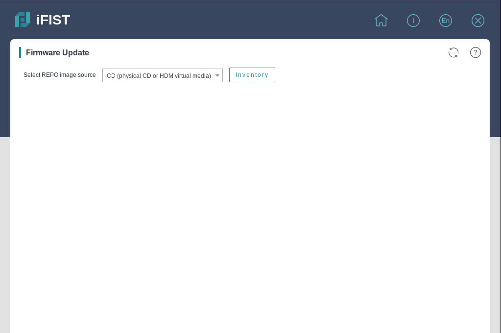
3. From the Select REPO image source list, select an image source. Options include CD and USB flash drive. If you select USB flash drive, you can select the target REPO image file from the level-2 list.
4. Click Inventory to start inventorying the firmware information in the REPO image file. To cancel an inventorying task in progress, click Stop inventorying.
5. After inventorying is completed, firmware products with the available versions later than the installed versions are automatically selected. Alternatively, you can manually select the firmware products to be updated.
Figure 37 Inventorying task completed
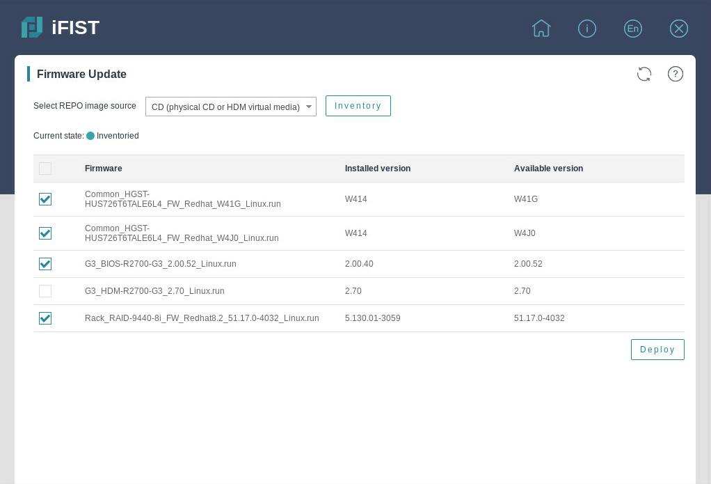
6. Click Deploy in the lower right corner to start updating the firmware products. To cancel a deployment task in progress, click Stop deployment.
7. After the firmware products are updated, different firmware products take effect in different ways, as shown in Table 8.
Table 8 Firmware effective ways
|
Firmware type |
Effective way |
|
HDM |
Restart the HDM. For more information, see the HDM user guide. |
|
BIOS |
Restart the server. To restart the
server, click |
|
CPLDs |
Different CPLDs take effect in different ways. For more information, see the firmware update guide. |
|
Storage controller firmware NIC firmware Hard disk firmware |
Restart the server. To restart the
server, click |
Parameters
· Inventory—Filter the firmware products applicable to the current server from the REPO image file.
· Deploy—Start to deploy the selected firmware products.
· Installed version—Version of the firmware installed in the current server.
· Available version—Version of the available firmware filtered from the REPO image file.
· State—State of the deployment task. Options include To be deployed, Deploying, Deployment failed, Deployment succeeded, and Firmware lost.
Updating iFIST
Procedure
1. Download the most recent iFIST image file from the H3C website to a storage media.
The storage media can be a physical drive or a virtual CD.
2. Mount the storage media to the server.
Make sure the server has only one bootable media mounted. If the server has multiple bootable media mounted, the server might fail to locate the correct boot media and upgrade of iFIST will fail as a result.
3. Select an upgrade option and start the upgrade process.
4. Reboot the server after the upgrade is complete.
5. Verify that iFIST is successfully upgraded.
Example: Updating iFIST on a server in UEFI boot mode
1. Sign in to HDM.
2. Mount the iFIST image file to the HDM remote console. This example uses an image file stored on a virtual CD.
a. On the HDM Web interface, navigate to the Remote Control > Remote Console page, as shown in Figure 38.
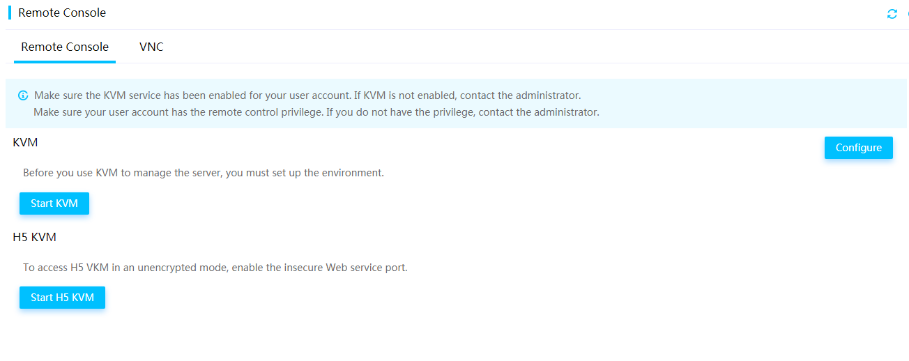
a. Click KVM to launch the KVM remote console.
b. Select Media > Virtual Media Wizard from the top menu bar.
The Virtual Media window opens and displays the CD/DVD tab by default, as shown in Figure 39.
Figure 39 Virtual Media window
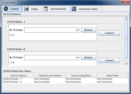
a. Click Browse next to a CD Image field to select the iFIST image file, and then click Open.
b. Click Connect.
3. Reboot the server.
The POST screen opens upon completion of the server initialization, as shown in Figure 40.
Figure 40 POST screen (BIOS version 2.00.26)
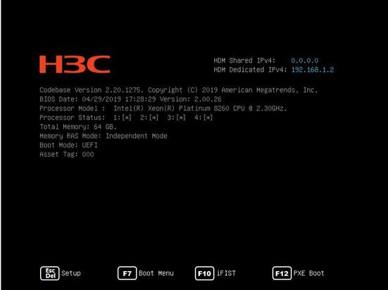
4. Press ESC or DEL.
The BIOS setup screen opens.
5. Select the Sava & Exit menu, as shown in Figure 41.
Figure 41 BIOS setup screen
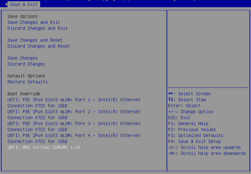
6. Select UEFI:AMI Virtual CDROM0 1.00 and press Enter.
The system starts to upgrade iFIST, as shown in Figure 42.
Figure 42 Upgrading iFIST
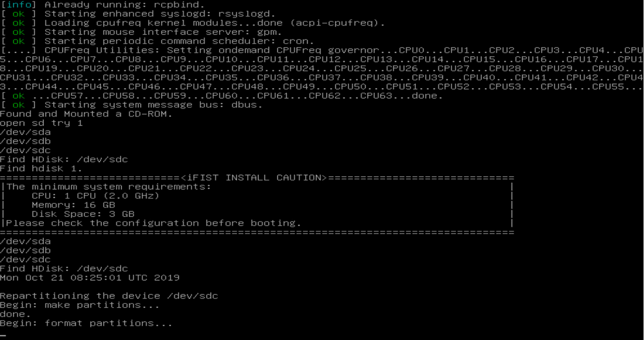
|
|
IMPORTANT: Do not remove the boot media during the upgrade process. If the boot media is removed before the upgrade completes, you must re-attach the boot media to the server, reboot the server, and restart the upgrade process. |
7. After the upgrade is complete, type yes and press Enter at the system prompt.
Figure 43 Completing iFIST upgrade
The system automatically ejects the installation media and displays a prompt, as shown in Figure 44.
Figure 44 Removing the installation media at the system prompt
8. Press Enter to reboot the server.
9. Launch iFIST.
10. On the Web interface of iFIST, and click ![]() in the
upper right corner to check the
iFIST version and verify that iFIST is upgraded successfully.
in the
upper right corner to check the
iFIST version and verify that iFIST is upgraded successfully.
FAQ
iFIST becomes unavailable after HDM is reset. How do I resolve the issue?
As a best practice, do not reset HDM while you are using iFIST. If you did so, reboot the server and then restart iFIST.
A logical drive is displayed with a garbled name in iFIST. How do I resolve the issue?
Delete the logical drive with the garbled name, and then create a new logical drive as needed.
When upgrading iFIST on a server that uses a USB flash drive as the boot device, iFIST got stuck on the GRUB page. How do I resolve the issue?
Remove the USB flash drive that contains the startup configuration file from the server, and then restart the iFIST upgrade process.
As a best practice, do not mount the ISO image and install a USB flash drive as the boot device at the same time.
The iFIST system installation module cannot detect the USB partition that does not have a UUID. How do I resolve the issue?
Reformat the USB partition or replace the USB flash drive with a new one.
iFIST cannot install the operating system on a RAID array created on the onboard RAID controller. Why?
The OS installation cannot be completed because iFIST cannot identify the drive letter of the RAID array created on the onboard RAID controller.
When installing the operating system, I choose to import configuration parameters from a file stored on a USB flash device. However, after waiting for a long time, the browser displays an unresponsive script warning message. How do I resolve the issue?
This symptom might occur if the USB flash drive used for the import contains a lot of files. As a result, the system to display an unresponsive script warning message when loading pages. Just click Continue to proceed.
As a best practice to improve user experience, avoid using a USB flash drive that contains a large number of files for configuration import to iFIST.
When the message "The firmware is being updated in an out-of-band manner from HDM. No operation is allowed. The system will restart automatically after the update. " pops up, how do I resolve the issue?
iFIST is not available because it is cooperating with HDM to update the firmware. After the update is complete, the servers will automatically restart according to the configuration of the system boot options. To access iFIST again, press F10 during the BIOS POST phase.
