- Table of Contents
-
- 17-Network Management and Monitoring Configuration Guide
- 00-Preface
- 01-System maintenance and debugging configuration
- 02-NQA configuration
- 03-NTP configuration
- 04-PoE configuration
- 05-SNMP configuration
- 06-RMON configuration
- 07-Event MIB configuration
- 08-NETCONF configuration
- 09-SmartMC configuration
- 10-CWMP configuration
- 11-EAA configuration
- 12-Process monitoring and maintenance configuration
- 13-Sampler configuration
- 14-Mirroring configuration
- 15-NetStream configuration
- 16-IPv6 NetStream configuration
- 17-sFlow configuration
- 18-Performance management configuration
- 19-Flow log configuration
- 20-Information center configuration
- 21-Packet capture configuration
- 22-Cloud connection configuration
- Title page
- Related Documents
-
| Title | Size | Download |
|---|---|---|
| 14-Mirroring configuration | 188.92 KB |
Contents
Restrictions and guidelines: Port mirroring configuration
Configuring local port mirroring
Restrictions and guidelines for local port mirroring configuration
Local port mirroring tasks at a glance
Creating a local mirroring group
Configuring Layer 3 remote port mirroring
Restrictions and guidelines for Layer 3 remote port mirroring configuration
Layer 3 remote port mirroring tasks at a glance
Prerequisites for Layer 3 remote port mirroring
Configuring local mirroring groups
Display and maintenance commands for port mirroring
Port mirroring configuration examples
Example: Configuring local port mirroring
Example: Configuring Layer 3 remote port mirroring
Restrictions: Hardware compatibility with flow mirroring
Restrictions and guidelines: Flow mirroring configuration
Flow mirroring tasks at a glance
Configuring a traffic behavior
Applying a QoS policy to an interface
Applying a QoS policy to the control plane
Flow mirroring configuration examples
Example: Configuring flow mirroring
Configuring port mirroring
About port mirroring
Port mirroring copies the packets passing through a port to a port that connects to a data monitoring device for packet analysis.
Terminology
The following terms are used in port mirroring configuration.
Mirroring source
The mirroring sources can be one or more monitored ports (called source ports).
Packets passing through mirroring sources are copied to a port connecting to a data monitoring device for packet analysis. The copies are called mirrored packets.
Source device
The device where the mirroring sources reside is called a source device.
Mirroring destination
The mirroring destination connects to a data monitoring device and is the destination port (also known as the monitor port) of mirrored packets. Mirrored packets are sent out of the monitor port to the data monitoring device.
A monitor port might receive multiple copies of a packet when it monitors multiple mirroring sources. For example, two copies of a packet are received on Port A when the following conditions exist:
· Port A is monitoring bidirectional traffic of Port B and Port C on the same device.
· The packet travels from Port B to Port C.
Destination device
The device where the monitor port resides is called the destination device.
Mirroring direction
The mirroring direction specifies the direction of the traffic that is copied on a mirroring source.
· Inbound—Copies packets received.
· Outbound—Copies packets sent.
· Bidirectional—Copies packets received and sent.
Mirroring group
Port mirroring is implemented through local mirroring groups. The mirroring sources and destination reside on the same device, which is directly connected to a data monitoring device. Packets received on the mirroring sources are sent through the mirroring destination to the data monitoring device.
Local port mirroring
Figure 1 Local port mirroring implementation
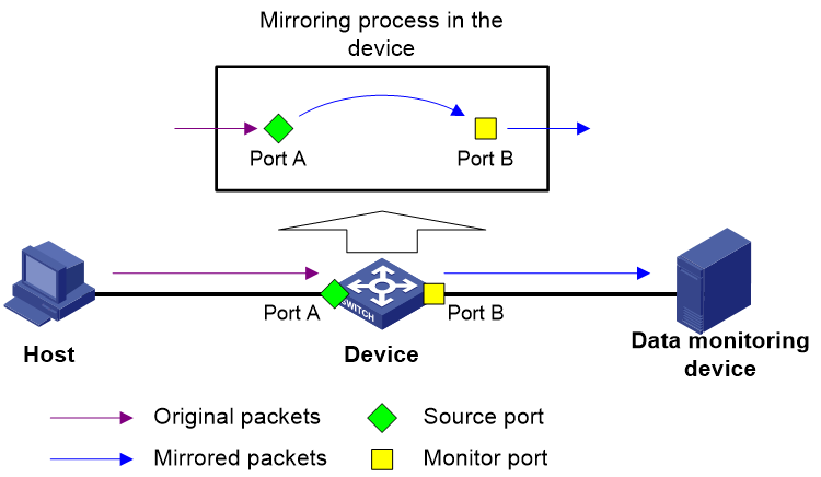
As shown in Figure 1, the source port (Port A) and the monitor port (Port B) reside on the same device. Packets received on Port A are copied to Port B. Port B then forwards the packets to the data monitoring device for analysis.
Layer 3 remote port mirroring
Layer 3 remote port mirroring is implemented through configuring a local mirroring group on both the source device and the destination device.
Configure the mirroring sources and destination for the local mirroring groups on the source device and destination device as follows:
· On the source device:
¡ Configure the ports to be monitored as source ports.
¡ Configure the tunnel interface through which mirrored packets are forwarded to the destination device as the monitor port.
· On the destination device:
¡ Configure the physical port corresponding to the tunnel interface as the source port.
¡ Configure the port that connects to the data monitoring device as the monitor port.
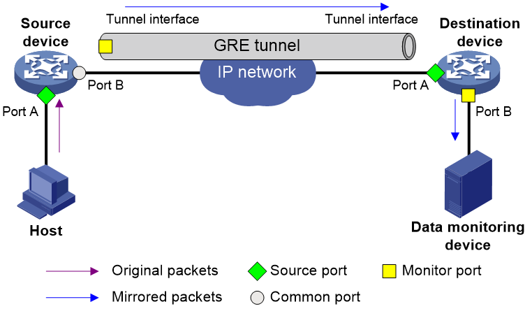
For example, in a network as shown in Figure 2, Layer 3 remote port mirroring works as follows:
1. The source device sends one copy of a packet received on the source port (Port A) to the tunnel interface.
The tunnel interface acts as the monitor port in the local mirroring group created on the source device.
2. The tunnel interface on the source device forwards the mirrored packet to the tunnel interface on the destination device through the GRE tunnel.
3. The destination device receives the mirrored packet from the physical interface of the tunnel interface.
The tunnel interface acts as the source port in the local mirroring group created on the destination device.
4. The physical interface of the tunnel interface sends one copy of the packet to the monitor port (Port B).
5. The monitor port (Port B) forwards the packet to the data monitoring device.
For more information about GRE tunnels and tunnel interfaces, see Layer 3—IP Services Configuration Guide.
Figure 2 Layer 3 remote port mirroring implementation
Restrictions and guidelines: Port mirroring configuration
If you configure a software forwarding interface as a source port for a mirroring group, the following rules apply:
· If the software forwarding interface operates in Layer 2 mode, the inbound and outbound IPv4 traffic, IPv6 traffic, and MPLS traffic of the interface will be mirrored.
· If the software forwarding interface operates in Layer 3 mode, the inbound and outbound IPv4 traffic, IPv6 traffic, and MPLS traffic of the interface will be mirrored. Make sure the interface has an IP address.
A software forwarding interface is an Ethernet interface. You can use the port link-mode command to change the link mode of an Ethernet interface. For more information, see Ethernet interface configuration in Interface Configuration Guide.
Configuring local port mirroring
Restrictions and guidelines for local port mirroring configuration
A local mirroring group takes effect only after it is configured with the monitor port and mirroring sources.
Port mirroring supports both software and hardware forwarding interfaces. However, you cannot assign a software forwarding interface and a hardware forwarding interface to the same mirroring group.
Local port mirroring tasks at a glance
To configure local port mirroring, perform the following tasks:
1. Creating a local mirroring group
2. Configuring mirroring sources
3. Configuring the monitor port
Creating a local mirroring group
1. Enter system view.
system-view
2. Create a local mirroring group.
mirroring-group group-id local
Configuring mirroring sources
Restrictions and guidelines for mirroring source configuration
When you configure source ports for a local mirroring group, follow these restrictions and guidelines:
· A mirroring group can contain multiple source ports.
· A port can act as a source port for only one mirroring group.
· A source port cannot be configured as a monitor port.
Configuring source ports
· Configure source ports in system view.
a. Enter system view.
system-view
b. Configure source ports for a local mirroring group.
mirroring-group group-id mirroring-port interface-list { both | inbound | outbound }
By default, no source port is configured for a local mirroring group.
· Configure source ports in interface view.
a. Enter system view.
system-view
b. Enter interface view.
interface interface-type interface-number
c. Configure the port as a source port for a local mirroring group.
mirroring-group group-id mirroring-port { both | inbound | outbound }
By default, a port does not act as a source port for any local mirroring groups.
Configuring the monitor port
Restrictions and guidelines
Do not enable the spanning tree feature on the monitor port.
Only one monitor port can be specified for a local mirroring group.
Use a monitor port only for port mirroring, so the data monitoring device receives only the mirrored traffic.
Procedure
· Configure the monitor port in system view.
a. Enter system view.
system-view
b. Configure the monitor port for a local mirroring group.
mirroring-group group-id monitor-port interface-type interface-number
By default, no monitor port is configured for a local mirroring group.
· Configure the monitor port in interface view.
a. Enter system view.
system-view
b. Enter interface view.
interface interface-type interface-number
c. Configure the port as the monitor port for a mirroring group.
mirroring-group group-id monitor-port
By default, a port does not act as the monitor port for any local mirroring groups.
Configuring Layer 3 remote port mirroring
Restrictions and guidelines for Layer 3 remote port mirroring configuration
To implement Layer 3 remote port mirroring, you must configure a unicast routing protocol on the intermediate devices to ensure Layer 3 reachability between the source and destination devices.
Layer 3 remote port mirroring tasks at a glance
Configuring the source device
1. Configuring local mirroring groups
2. Configuring mirroring sources
3. Configuring the monitor port
Configuring the destination device
1. Configuring local mirroring groups
2. Configuring mirroring sources
3. Configuring the monitor port
Prerequisites for Layer 3 remote port mirroring
Before configuring Layer 3 remote mirroring, complete the following tasks:
· Create a tunnel interface and a GRE tunnel.
· Configure the source and destination addresses of the tunnel interface as the IP addresses of the physical interfaces on the source and destination devices, respectively.
For more information about tunnel interfaces, see Layer 3—IP Services Configuration Guide.
Configuring local mirroring groups
Restrictions and guidelines
Configure a local mirroring group on both the source device and the destination device.
Procedure
1. Enter system view.
system-view
2. Create a local mirroring group.
mirroring-group group-id local
Configuring mirroring sources
Restrictions and guidelines for mirroring source configuration
When you configure source ports for a local mirroring group, follow these restrictions and guidelines:
· On the source device, configure the ports you want to monitor as the source ports. On the destination device, configure the physical interface corresponding to the tunnel interface as the source port.
· A port can act as a source port for only one mirroring group.
· A source port cannot be configured as a monitor port.
Configuring source ports
· Configure source ports in system view.
a. Enter system view.
system-view
b. Configure source ports for a local mirroring group.
mirroring-group group-id mirroring-port interface-list { both | inbound | outbound }
By default, no source port is configured for a local mirroring group.
· Configure source ports in interface view.
a. Enter system view.
system-view
b. Enter interface view.
interface interface-type interface-number
c. Configure the port as a source port for a local mirroring group.
mirroring-group group-id mirroring-port { both | inbound | outbound }
By default, a port does not act as a source port for any local mirroring groups.
Configuring the monitor port
Restrictions and guidelines for monitor port configuration
On the source device, configure a tunnel interface as a monitor port. On the destination device, configure the port that connects to a data monitoring device as a monitor port.
On the source device, only one tunnel interface can be configured as the monitor port for a local mirroring group.
On the destination device, do not enable the spanning tree feature on the monitor port.
On the destination device, only one monitor port can be specified for a local mirroring group.
Use a monitor port only for port mirroring, so the data monitoring device receives only the mirrored traffic.
Procedure
· Configure the monitor port in system view.
a. Enter system view.
system-view
b. Configure the monitor port for a local mirroring group.
mirroring-group group-id monitor-port interface-type interface-number
By default, no monitor port is configured for a local mirroring group.
· Configure the monitor port in interface view.
a. Enter system view.
system-view
b. Enter interface view.
interface interface-type interface-number
c. Configure the port as the monitor port for a local mirroring group.
mirroring-group group-id monitor-port
By default, a port does not act as the monitor port for any local mirroring groups.
Display and maintenance commands for port mirroring
Execute display commands in any view.
|
Task |
Command |
|
Display mirroring group information. |
display mirroring-group { group-id | all | local } |
Port mirroring configuration examples
Example: Configuring local port mirroring
Network configuration
As shown in Figure 3, configure local port mirroring in source port mode to enable the server to monitor the bidirectional traffic of the marketing and technical departments.

Procedure
# Create local mirroring group 1.
<Device> system-view
[Device] mirroring-group 1 local
# Configure GigabitEthernet 1/0/1 and GigabitEthernet 1/0/2 as source ports for local mirroring group 1.
[Device] mirroring-group 1 mirroring-port gigabitethernet 1/0/1 gigabitethernet 1/0/2 both
# Configure GigabitEthernet 1/0/3 as the monitor port for local mirroring group 1.
[Device] mirroring-group 1 monitor-port gigabitethernet 1/0/3
# Disable the spanning tree feature on the monitor port (GigabitEthernet 1/0/3).
[Device] interface gigabitethernet 1/0/3
[Device-GigabitEthernet1/0/3] undo stp enable
[Device-GigabitEthernet1/0/3] quit
Verifying the configuration
# Verify the mirroring group configuration.
[Device] display mirroring-group all
Mirroring group 1:
Type: Local
Status: Active
Mirroring port:
GigabitEthernet1/0/1 Both
GigabitEthernet1/0/2 Both
Monitor port: GigabitEthernet1/0/3
Example: Configuring Layer 3 remote port mirroring
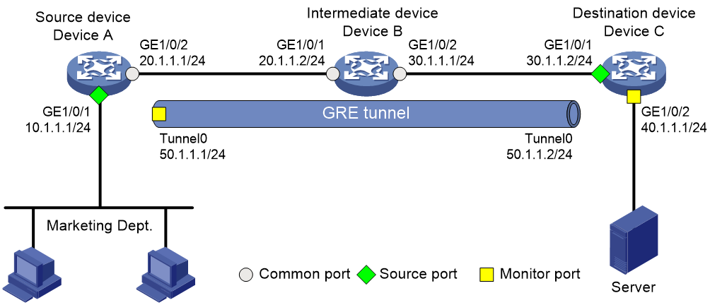
Network configuration
On a Layer 3 network shown in Figure 4, configure Layer 3 remote port mirroring to enable the server to monitor the bidirectional traffic of the Marketing Department.
Procedure
1. Configure IP addresses for the tunnel interfaces and related ports on the devices. (Details not shown.)
2. Configure Device A (the source device):
# Create tunnel interface Tunnel 0 that operates in GRE mode, and configure an IP address and subnet mask for the interface.
<DeviceA> system-view
[DeviceA] interface tunnel 0 mode gre
[DeviceA-Tunnel0] ip address 50.1.1.1 24
# Configure source and destination IP addresses for Tunnel 0.
[DeviceA-Tunnel0] source 20.1.1.1
[DeviceA-Tunnel0] destination 30.1.1.2
[DeviceA-Tunnel0] quit
# Enable the OSPF protocol.
[DeviceA] ospf 1
[DeviceA-ospf-1] area 0
[DeviceA-ospf-1-area-0.0.0.0] network 10.1.1.0 0.0.0.255
[DeviceA-ospf-1-area-0.0.0.0] network 20.1.1.0 0.0.0.255
[DeviceA-ospf-1-area-0.0.0.0] quit
[DeviceA-ospf-1] quit
# Create local mirroring group 1.
[DeviceA] mirroring-group 1 local
# Configure GigabitEthernet 1/0/1 as a source port and Tunnel 0 as the monitor port of local mirroring group 1.
[DeviceA] mirroring-group 1 mirroring-port gigabitethernet 1/0/1 both
[DeviceA] mirroring-group 1 monitor-port tunnel 0
3. Enable the OSPF protocol on Device B (the intermediate device).
<DeviceB> system-view
[DeviceB] ospf 1
[DeviceB-ospf-1] area 0
[DeviceB-ospf-1-area-0.0.0.0] network 20.1.1.0 0.0.0.255
[DeviceB-ospf-1-area-0.0.0.0] network 30.1.1.0 0.0.0.255
[DeviceB-ospf-1-area-0.0.0.0] quit
[DeviceB-ospf-1] quit
4. Configure Device C (the destination device):
# Create tunnel interface Tunnel 0 that operates in GRE mode, and configure an IP address and subnet mask for the interface.
<DeviceC> system-view
[DeviceC] interface tunnel 0 mode gre
[DeviceC-Tunnel0] ip address 50.1.1.2 24
# Configure source and destination IP addresses for Tunnel 0.
[DeviceC-Tunnel0] source 30.1.1.2
[DeviceC-Tunnel0] destination 20.1.1.1
[DeviceC-Tunnel0] quit
# Enable the OSPF protocol.
[DeviceC] ospf 1
[DeviceC-ospf-1] area 0
[DeviceC-ospf-1-area-0.0.0.0] network 30.1.1.0 0.0.0.255
[DeviceC-ospf-1-area-0.0.0.0] network 40.1.1.0 0.0.0.255
[DeviceC-ospf-1-area-0.0.0.0] quit
[DeviceC-ospf-1] quit
# Create local mirroring group 1.
[DeviceC] mirroring-group 1 local
# Configure GigabitEthernet 1/0/1 as a source port for local mirroring group 1.
[DeviceC] mirroring-group 1 mirroring-port gigabitethernet 1/0/1 inbound
# Configure GigabitEthernet 1/0/2 as the monitor port for local mirroring group 1.
[DeviceC] mirroring-group 1 monitor-port gigabitethernet 1/0/2
Verifying the configuration
# Verify the mirroring group configuration on Device A.
[DeviceA] display mirroring-group all
Mirroring group 1:
Type: Local
Status: Active
Mirroring port:
GigabitEthernet1/0/1 Both
Monitor port: Tunnel0
# Display information about all mirroring groups on Device C.
[DeviceC] display mirroring-group all
Mirroring group 1:
Type: Local
Status: Active
Mirroring port:
GigabitEthernet1/0/1 Inbound
Configuring flow mirroring
About flow mirroring
Flow mirroring copies packets matching a class to a destination for packet analyzing and monitoring. It is implemented through QoS.
To implement flow mirroring through QoS, perform the following tasks:
· Define traffic classes and configure match criteria to classify packets to be mirrored. Flow mirroring allows you to flexibly classify packets to be analyzed by defining match criteria.
· Configure traffic behaviors to mirror the matching packets to the specified destination.
For more information about QoS policies, traffic classes, and traffic behaviors, see ACL and QoS Configuration Guide.
Restrictions: Hardware compatibility with flow mirroring
|
Hardware |
Flow mirroring compatibility |
|
MSR810, MSR810-W, MSR810-W-DB, MSR810-LM, MSR810-W-LM, MSR810-10-PoE, MSR810-LM-HK, MSR810-W-LM-HK, MSR810-LM-CNDE-SJK, MSR810-CNDE-SJK |
Yes |
|
MSR810-LMS, MSR810-LUS |
Yes |
|
MSR810-LMS-EA, MSR810-LME |
Yes |
|
MSR2600-6-X1, MSR2600-10-X1 |
Yes |
|
MSR 2630 |
Yes |
|
MSR3600-28, MSR3600-51 |
Yes |
|
MSR3600-28-SI, MSR3600-51-SI |
Yes |
|
MSR3600-28-X1, MSR3600-28-X1-DP, MSR3600-51-X1, MSR3600-51-X1-DP |
Yes |
|
MSR3610-I-DP, MSR3610-IE-DP, MSR3610-IE-ES, MSR3610-IE-EAD, MSR3610-I-IG, MSR3610-IE-IG |
Yes |
|
MSR3610-X1, MSR3610-X1-DP, MSR3610-X1-DC, MSR3610-X1-DP-DC |
Yes |
|
MSR 3610, MSR 3620, MSR 3620-DP, MSR 3640, MSR 3660 |
Yes |
|
MSR3610-G, MSR3620-G |
No |
|
Hardware |
Flow mirroring compatibility |
|
MSR810-W-WiNet, MSR810-LM-WiNet |
Yes |
|
MSR830-4LM-WiNet |
Yes |
|
MSR830-5BEI-WiNet, MSR830-6EI-WiNet, MSR830-10BEI-WiNet |
Yes |
|
MSR830-6BHI-WiNet, MSR830-10BHI-WiNet |
Yes |
|
MSR2600-6-WiNet , MSR2600-10-X1-WiNet |
Yes |
|
MSR2630-WiNet |
Yes |
|
MSR3600-28-WiNet |
Yes |
|
MSR3610-X1-WiNet |
Yes |
|
MSR3610-WiNet, MSR3620-10-WiNet, MSR3620-DP-WiNet, MSR3620-WiNet, MSR3660-WiNet |
Yes |
|
Hardware |
Flow mirroring compatibility |
|
MSR2630-XS |
Yes |
|
MSR3600-28-XS |
Yes |
|
MSR3610-XS |
Yes |
|
MSR3620-XS |
Yes |
|
MSR3610-I-XS |
Yes |
|
MSR3610-IE-XS |
Yes |
|
Hardware |
Flow mirroring compatibility |
|
MSR810-LM-GL |
Yes |
|
MSR810-W-LM-GL |
Yes |
|
MSR830-6EI-GL |
Yes |
|
MSR830-10EI-GL |
Yes |
|
MSR830-6HI-GL |
Yes |
|
MSR830-10HI-GL |
Yes |
|
MSR2600-6-X1-GL |
Yes |
|
MSR3600-28-SI-GL |
Yes |
Restrictions and guidelines: Flow mirroring configuration
For information about the configuration commands except the mirror-to command, see QoS policy commands in ACL and QoS Command Reference.
Flow mirroring tasks at a glance
To configure flow mirroring, perform the following tasks:
1. Configuring a traffic class
A traffic class defines the criteria that filters the traffic to be mirrored.
2. Configuring a traffic behavior
A traffic behavior specifies mirroring destinations.
Choose one of the following tasks:
¡ Applying a QoS policy to an interface
¡ Applying a QoS policy to the control plane
Configuring a traffic class
1. Enter system view.
system-view
2. Create a class and enter class view.
traffic classifier classifier-name [ operator { and | or } ]
3. Configure match criteria.
if-match [ not ] match-criteria
By default, no match criterion is configured in a traffic class.
4. (Optional.) Display traffic class information.
display traffic classifier
This command is available in any view.
Configuring a traffic behavior
1. Enter system view.
system-view
2. Create a traffic behavior and enter traffic behavior view.
traffic behavior behavior-name
3. Mirror traffic to an interface.
mirror-to interface interface-type interface-number
By default, no mirroring actions exist to mirror traffic to interfaces.
Flow mirroring does not support mirroring traffic to Layer 3 Ethernet interfaces.
4. (Optional.) Display traffic behavior configuration.
display traffic behavior
This command is available in any view.
Configuring a QoS policy
1. Enter system view.
system-view
2. Create a QoS policy and enter QoS policy view.
qos policy policy-name
3. Associate a class with a traffic behavior in the QoS policy.
classifier classifier-name behavior behavior-name
By default, no traffic behavior is associated with a class.
4. (Optional.) Display QoS policy configuration.
display qos policy
This command is available in any view.
Applying a QoS policy
Applying a QoS policy to an interface
Restrictions and guidelines
You can apply a QoS policy to an interface to mirror the traffic of the interface.
A policy can be applied to multiple interfaces.
In one traffic direction of an interface, only one QoS policy can be applied.
Procedure
1. Enter system view.
system-view
2. Enter interface view.
interface interface-type interface-number
3. Apply a policy to the interface.
qos apply policy policy-name { inbound | outbound }
4. (Optional.) Display the QoS policy applied to the interface.
display qos policy interface
This command is available in any view.
Applying a QoS policy to the control plane
Restrictions and guidelines
You can apply a QoS policy to the control plane to mirror the traffic of all ports on the control plane.
Procedure
1. Enter system view.
system-view
2. Enter control plane view.
In standalone mode:
control-plane
In IRF mode:
control-plane slot slot-number
3. Apply a QoS policy to the control plane.
qos apply policy policy-name inbound
4. (Optional.) Display QoS policies applied to the control plane
display qos policy control-plane
This command is available in any view.
Flow mirroring configuration examples
Example: Configuring flow mirroring
Network configuration
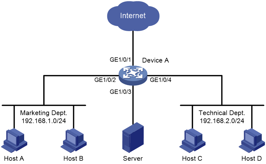
As shown in Figure 5, configure flow mirroring so that the server can monitor the following traffic:
· All traffic that the Technical Department sends to access the Internet.
· IP traffic that the Technical Department sends to the Marketing Department during working hours (8:00 to 18:00) on weekdays.
Procedure
# Create working hour range work, in which working hours are from 8:00 to 18:00 on weekdays.
<DeviceA> system-view
[DeviceA] time-range work 8:00 to 18:00 working-day
# Create IPv4 advanced ACL 3000 to allow packets from the Technical Department to access the Internet and the Marketing Department during working hours.
[DeviceA] acl advanced 3000
[DeviceA-acl-ipv4-adv-3000] rule permit tcp source 192.168.2.0 0.0.0.255 destination-port eq www
[DeviceA-acl-ipv4-adv-3000] rule permit ip source 192.168.2.0 0.0.0.255 destination 192.168.1.0 0.0.0.255 time-range work
[DeviceA-acl-ipv4-adv-3000] quit
# Create traffic class tech_c, and configure the match criterion as ACL 3000.
[DeviceA] traffic classifier tech_c
[DeviceA-classifier-tech_c] if-match acl 3000
[DeviceA-classifier-tech_c] quit
# Create traffic behavior tech_b, configure the action of mirroring traffic to GigabitEthernet 1/0/3.
[DeviceA] traffic behavior tech_b
[DeviceA-behavior-tech_b] mirror-to interface gigabitethernet 1/0/3
[DeviceA-behavior-tech_b] quit
# Create QoS policy tech_p, and associate traffic class tech_c with traffic behavior tech_b in the QoS policy.
[DeviceA] qos policy tech_p
[DeviceA-qospolicy-tech_p] classifier tech_c behavior tech_b
[DeviceA-qospolicy-tech_p] quit
# Apply QoS policy tech_p to the incoming packets of GigabitEthernet 1/0/4.
[DeviceA] interface gigabitethernet 1/0/4
[DeviceA-GigabitEthernet1/0/4] qos apply policy tech_p inbound
[DeviceA-GigabitEthernet1/0/4] quit
Verifying the configuration
# Verify that the server can monitor the following traffic:
· All traffic sent by the Technical Department to access the Internet.
· IP traffic that the Technical Department sends to the Marketing Department during working hours on weekdays.
(Details not shown.)
