- Table of Contents
-
- 08-Layer 3—IP Routing Configuration Guide
- 00-Preface
- 01-Basic IP routing configuration
- 02-Static routing configuration
- 03-RIP configuration
- 04-OSPF configuration
- 05-IS-IS configuration
- 06-EIGRP configuration
- 07-BGP configuration
- 08-Policy-based routing configuration
- 09-IPv6 static routing configuration
- 10-RIPng configuration
- 11-OSPFv3 configuration
- 12-IPv6 policy-based routing configuration
- 13-Routing policy configuration
- 14-MTR configuration
- 15-RIR configuration
- Related Documents
-
| Title | Size | Download |
|---|---|---|
| 15-RIR configuration | 602.57 KB |
Preference-based link selection
Bandwidth-based link selection
About bandwidth-based link selection
Bandwidth-based link selection policy
Per-session weight-based link selection mode
Per-session periodic link adjustment mode
Link selection delay and suppression
Link selection workflow summary
Preference-based primary link selection
Preference-based backup link selection
Quality tolerant link selection
Bandwidth tolerant link selection
Restrictions: Hardware compatibility with RIR
Spoke configuration tasks at a glance
Hub configuration tasks at a glance
Prerequisites for RIR configuration
Specifying an RIR client synchronization port
Configuring NQA link connectivity probe parameters
Configuring an NQA link quality operation
Specifying an RIR server synchronization port
Creating an SLA and an NQA link quality operation
Assigning a link type and index to a VSI interface
Configuring the link bandwidth of a VXLAN tunnel interface
About flow template configuration
Configuring a quality policy for the flow template
Specifying the per-session expected bandwidth
Specifying link preference values for links
Configuring the link load balancing mode
Restrictions and guidelines for link load balancing mode configuration
Setting the per-session periodic link adjustment mode
Setting the per-packet load balancing mode
Configuring flow priority-based traffic scheduling
Setting the link selection delay and link selection suppression period
Configuring a QoS policy to mark matching packets with a flow ID
About configuring a QoS policy to mark matching packets with a flow ID
Creating a traffic class and defining packet match criteria
Creating a traffic behavior and configuring a flow ID marking action
Applying the QoS policy to an interface
Restrictions and guidelines for RIR collaboration configuration
Setting up RIR dedicated links between local and peer devices
Applying QoS policies to interfaces interconnecting local and peer devices
Assigning links to an RIR collaboration link group
Establishing RIR collaboration relationship for each pair of local and peer devices
Configuring RIR packet redirection
Configuring flow ID-based traffic rate statistics for tunnels
Display and maintenance commands for RIR
Example: Configuring RIR in a VXLAN-based hub-spoke network
Configuring RIR
About RIR
Resilient Intelligent Routing (RIR) dynamically selects the most suitable links for traffic forwarding based on service requirements (for example, link quality and link bandwidth). RIR not only can select the optimal link from a specific type of transport network, but also can perform automatic link switchover when the current link becomes unqualified.
Application scenario
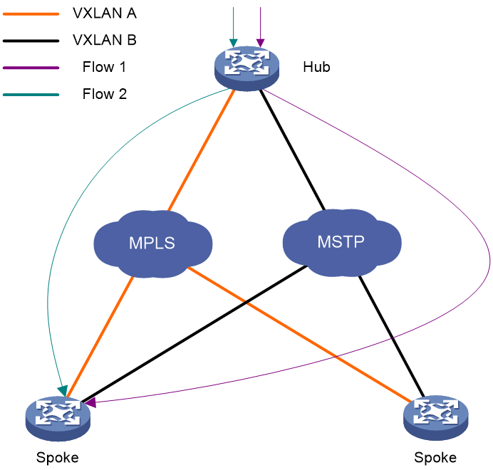
As shown in Figure 1, RIR is used in a VXLAN-based hub-spoke network. The feature can select different VXLAN tunnels to forward traffic for different services, depending on parameters including the link preference, link primary/backup role, link quality, and link bandwidth. RIR can perform link selection not only for traffic from a hub to a spoke, but also for traffic from a spoke to a hub. The feature might select different links for bidirectional traffic between a hub and a spoke.
Figure 1 RIR application scenario
Flow template
A flow template defines link selection policies for a type of service flow. A flow ID uniquely identifies a flow template.
The device applies the link selection policies under a flow template to the service flow marked with the flow ID of the flow template.
The device supports using QoS policies to mark flow IDs for service flows. After QoS identifies the service of a packet based on the quintuple and DSCP of the packet, it assigns a flow ID to the packet. Then, RIR will perform link selection for the packet based on the flow template that uses the flow ID.
The flow ID is marked only in the RIR process, and it will not be added to any outgoing packets.
For more information about QoS marking, see QoS overview, QoS policies, and marking configuration in ACL and QoS Configuration Guide.
Link type
RIR uses the link type to identify the network type of a link and uses the link index to distinguish links of the same network type. RIR supports 4G, Internet, MPLS, and MSTP link types. The link type is used only for identifying links, and it does not affect packet encapsulation.
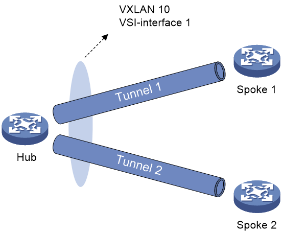
As shown in Figure 2, assign a link type and link index to the VSI interface to identify the VXLAN tunnels between the hub and the spokes in the VXLAN. To uniquely identify a VXLAN tunnel between a hub and a spoke, VXLAN-based RIR allows the hub and spoke to have only one VXLAN tunnel for each VSI interface.
Figure 2 Links in a VXLAN network
Preference-based link selection
Link preference
You can assign a preference to a link based on factors such as the service requirements, the link conditions, and the link cost. RIR preferentially selects links with higher preference.
VXLAN-based RIR supports assigning a link preference to a type of links with a specific link index in flow template view. The link type and link index identify a VSI interface. As VXLAN-based RIR allows a hub and spoke to have only one VXLAN tunnel for a VSI interface, the link preference of the VSI interface is the link preference of the VXLAN tunnel between the hub and spoke.
Link selection rules
You can assign the same preference value to different links in the same flow template.
RIR selects a link for a type of service flows from the links in the flow template in descending order of link preference. If the links with the highest preference cannot meet the service requirements, RIR tries the links with the second highest preference, and so forth to the links with the lowest preference.
If the flow template has two or more links with the same preference, RIR performs link selection based on RIR link load sharing criteria.
Redundant link selection
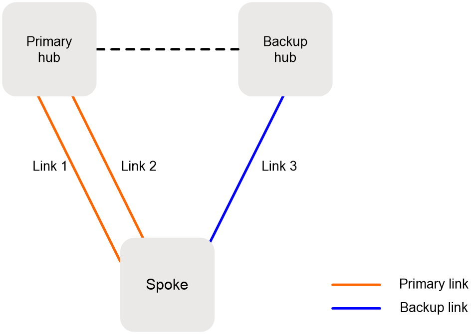
To ensure service high availability, redundant hubs are deployed. Typically, use the links between a spoke and the primary hub as primary links, and use the links between a spoke and the backup hub as backup links. When no link is available to reach the primary hub, the spoke can switch traffic to the backup hub to ensure service continuity.
A VXLAN tunnel is a primary link by default after it is assigned a link preference based on the link type and index on its VSI interface. To specify a VXLAN tunnel associated with a VSI interface as a backup link, specify that VXLAN tunnel as an RIR backup tunnel.
As shown in Figure 3, when primary links 1 and 2 are not available, the spoke uses backup link 3 to forward traffic to the backup hub.
Figure 3 Primary and backup links
Quality-based link selection
RIR server and RIR client
About the RIR server and RIR client
In a hub-spoke network, a hub is typically connected to multiple spokes. To avoid the hub from consuming too many resources on link quality detection by Network Quality Analyzer (NQA) probes, RIR provides the following roles:
· RIR server—An RIR server does not perform NQA link probes. It performs link selection based on the link quality probe results synchronized from RIR clients.
· RIR client—An RIR client performs NQA link probes to detect the link quality and synchronizes the link quality probe results to RIR servers.
Configure a hub as an RIR server and spokes as RIR clients, so the hub can perform link selection based on the link quality probe results synchronized from the RIR clients.
RIR server function
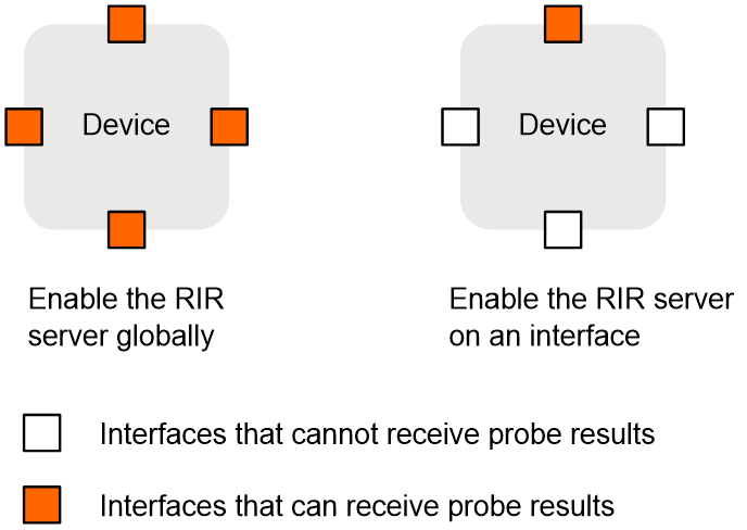
You can enable the RIR server globally or on an interface, as shown in Figure 4.
· If you enable the RIR server globally, the RIR server is also enabled on all interfaces on the device. The interfaces can receive RIR link quality probe results from RIR clients.
· If you enable the RIR server on an interface, only that interface can receive RIR link quality probe results from RIR clients.
|
|
IMPORTANT: In a VXLAN network, only tunnel interfaces support enabling the RIR server. The RIR server uses the tunnel interfaces to receive RIR link quality probe results from RIR clients. |
Figure 4 Enabling the RIR server
RIR client function
The RIR client synchronizes link quality probe results to RIR servers. Enabling the RIR client is the same as enabling the RIR server.
RIR server and client enabling policy
Enable the RIR server or RIR client, or use them in combination, depending on the role of the device in the network.
· If the device acts only as a hub, you can enable the RIR server globally.
· If the device acts only as a spoke, you can enable the RIR client globally.
· If the device acts as both a hub and a spoke, you can enable the RIR server and RIR client on the corresponding interfaces.
The RIR server and RIR client cannot be both enabled on the same interface. If the enabled role (RIR server or client) on an interface is different from the globally enabled role, the interface-specific role takes effect on that interface.
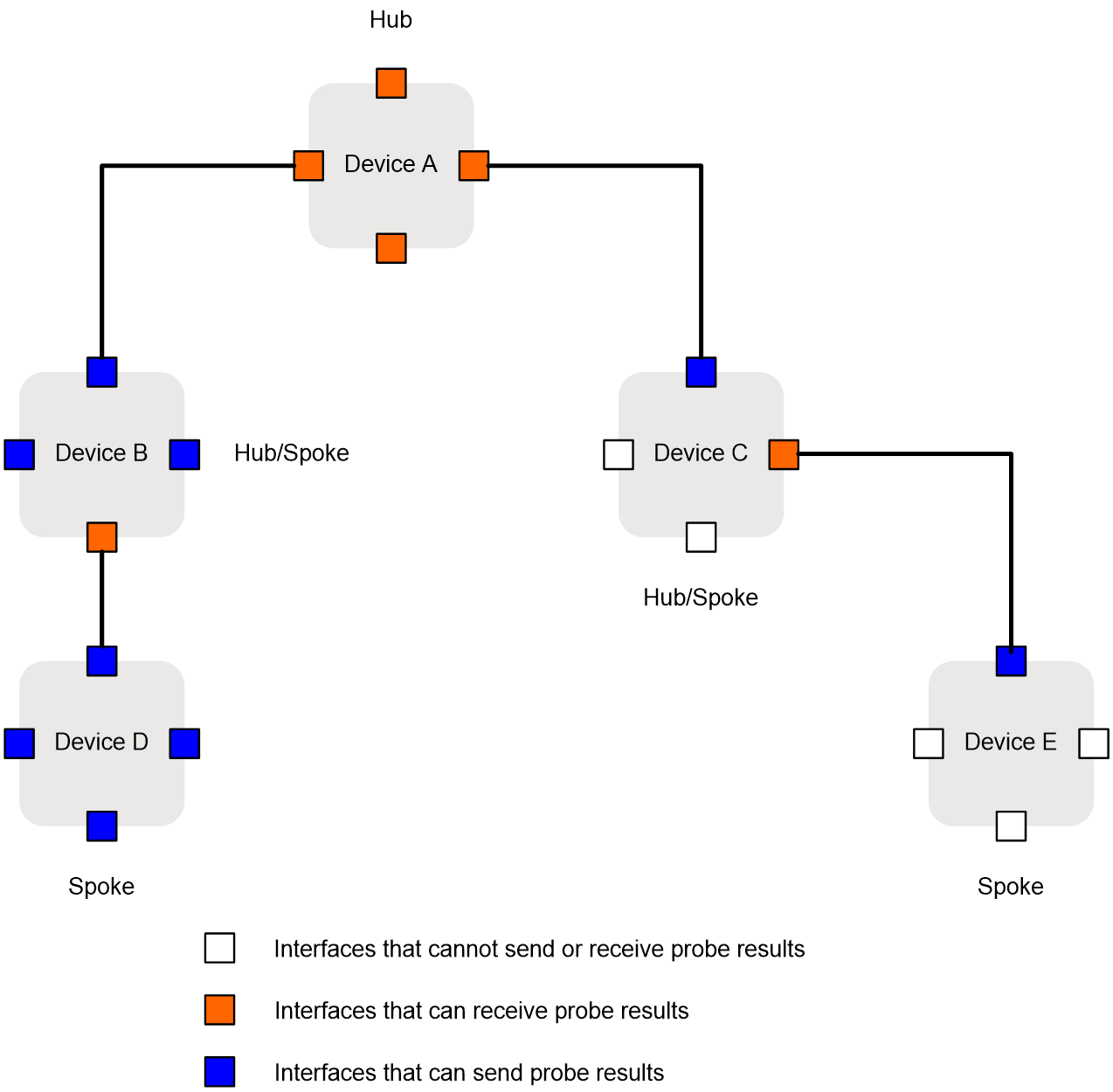
As shown in Figure 5, enable the global and interface-specific RIR server and RIR client in combination as follows:
· Device A—Enable the RIR server globally.
· Device B—Enable the RIR client globally and enable the RIR server on an interface.
· Device C—Enable the RIR client on an interface and enable the RIR server on an interface.
· Device D—Enable the RIR client globally.
· Device E—Enable the RIR client on an interface.
Figure 5 Enabling the RIR server and client
NQA link probes
RIR uses NQA to detect the status of candidate links and selects the most suitable link based on the NQA link quality probe results. For more information about NQA, see Network Management and Monitoring Configuration Guide.
A hub performs link selection based on the link quality probe results synchronized from spokes. RIR uses spokes as NQA clients and hubs as NQA servers. The following types of NQA link probe operations are defined:
· NQA link connectivity probe operation—Performs ICMP echo probes to check the connectivity of each link. If a link is disconnected, RIR does not perform NQA link quality probes on that link. You can configure only one NQA link connectivity probe operation.
· NQA link quality probe operations—Also referred to as NQA link quality operations, perform UDP jitter probes to detect the link delay, jitter, and packet loss ratio for links that pass NQA link connectivity check. You can configure multiple NQA link quality operations. The operations might offer different link quality probe results for the same link.
The device performs NQA probes only for links that are assigned link types and link indexes.
SLA
To meet the differentiated requirements of services on link quality, configure a Service Level Agreement (SLA) for each service. An SLA contains a set of link quality evaluation thresholds, including the link delay threshold, packet loss threshold, and jitter threshold.
The quality policy of a flow template contains an SLA and an NQA link quality operation. By comparing the NQA link quality probe results with the thresholds in the SLA, the device determines whether a link meets the quality requirements of the service. If all parameter values in the probe results of a link are lower than or equal to the thresholds in the SLA, the link is qualified for the service.
Quality policy
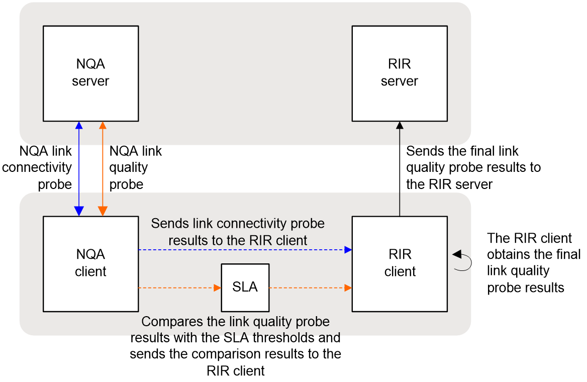
Link quality probe results
As shown in Figure 6, if a flow template is configured with a quality policy, the spoke determines whether a link is qualified for that type of service flow based on the NQA link quality probe results. In addition, the spoke synchronizes the link quality probe results to the hub. The hub performs link selection based on the link quality probe results synchronized from the spoke. You only need to configure the quality policy on the spoke.
RIR uses the following rules to determine whether a link is qualified for a type of service flow:
· If the link fails NQA link connectivity check, RIR determines that the link is unqualified.
· If the link passes NQA link connectivity check, RIR checks the NQA link quality probe results for the link.
¡ If all link quality parameter values in the probe results are lower than or equal to the link quality thresholds in the SLA, RIR determines that the link is qualified.
¡ If any link quality parameter value in the probe results is higher than the corresponding link quality threshold in the SLA, RIR determines that the link is unqualified.
Figure 6 Link quality probe result processing network diagram
Quality-based link selection on a hub and a spoke
When a spoke performs quality-based link selection, it considers only the quality policy configured on the spoke. If a quality policy has been configured in a flow template on the spoke, the spoke calculates link quality probe results based on the NQA link quality operation and SLA in the quality policy. Then, the spoke performs link selection for the flow that matches the flow template based on the link quality probe results. If no quality policy is configured in a flow template on the spoke, the spoke does not consider the quality factor when it performs link selection. All links in the flow template meet the service requirements in quality.
When a hub performs quality-based link selection for traffic sent to a spoke, it considers the quality policies both on the hub and spoke. Table 1 shows the link selection rules for a flow that matches a flow template on a hub.
Table 1 Quality-based link selection rules on a hub
|
Whether a quality policy is configured on the hub |
Whether a quality policy is configured on the spoke |
Quality-based link selection rules on the hub |
|
Yes |
Yes |
The hub performs link selection based on the link quality probe results synchronized from the spoke. |
|
Yes |
No |
The spoke does not synchronize link quality probe results to the hub. The hub determines that no link in the flow template meets the quality requirements. |
|
No |
Yes |
The spoke synchronizes link quality probe results to the hub. The hub determines that all links in the flow template are qualified for packets that match the flow template. |
|
No |
No |
The spoke does not synchronize link quality probe results to the hub. The hub determines that all links in the flow template are qualified for packets that match the flow template. |
As a best practice, configure a quality policy both on the hub and spoke for a type of service flow or do not configure any quality policy on the hub or spoke for the type of service flow.
Bandwidth-based link selection
About bandwidth-based link selection
Bandwidth-based link selection not only can select links that meet the service bandwidth requirements, but also can load share service traffic among multiple links. This manner can avoid a link from being overwhelmed or congested.
Bandwidth-based link selection policy
Bandwidth-based link selection enables the device to select a suitable link for service traffic based on the used bandwidth of the link, the total link bandwidth, and the per-session expected bandwidth. The device can automatically obtain the used bandwidth of the link. The total bandwidth of the link and the per-session expected bandwidth are manually configured or calculated based on the user configuration.
The device uses sessions as the minimum granularity and performs bandwidth-based link selection to achieve refined link bandwidth management. A session is uniquely defined by a quintuple including the source IP address, destination IP address, source port, destination port, and transport layer protocol.
When the device selects links for traffic of a session, it first performs bandwidth detection based on the per-session expected bandwidth in the flow template to which the session belongs. If the used bandwidth plus the per-session expected bandwidth of a candidate link is less than 80% of its total bandwidth, the available bandwidth of the link meets the session bandwidth requirements. The link passes the bandwidth detection.
When different sessions of the same service type use the same link selection policy, the link selection results might be different.
Load balancing
Load balancing modes
If multiple links are available for sessions that match a flow template, the device distributes the traffic of the sessions to these links for load balancing based on the link bandwidths. RIR supports the following load balancing modes:
· Per-session weight-based link selection mode—RIR global link load balancing mode that takes effect on all RIR flows. This mode can distribute the sessions that match the same flow template to different links according to the weights of the links. RIR selects only one link to transmit a session.
· Per-session periodic link adjustment mode—RIR global link load balancing mode that takes effect on all RIR flows. This mode not only can distribute the sessions that match the same flow template to different links, but also can periodically adjust links for the sessions. Within one adjustment period, RIR selects only one link to transmit a session.
· Per-packet mode—Flow-specific link load balancing mode that takes effect only on traffic that matches the flow template where this mode is enabled. This mode can distribute the same session to different links for transmission.
The per-packet mode takes precedence over the per-session modes.
Load balancing concepts
Bandwidth weight
The bandwidth of a link is used as the weight of the link. If the total bandwidth of a link is used as the link weight, the weight is called the total bandwidth weight. If the remaining bandwidth of a link is used as the link weight, the weight is called the remaining bandwidth weight.
To select links from multiple links based on their bandwidth weights, the probability that each link is selected equals to the ratio of the bandwidth of a single link to the bandwidth sum of all the links. The bandwidth sum of all the links is the weight sum.
For example, the total bandwidths of links 1, 2, and 3 are 10 Mbps, 10 Mbps, and 20 Mbps, respectively. The remaining bandwidths of links 1, 2, and 3 are 8 Mbps, 4 Mbps, and 8 Mbps, respectively. All the links meet the service requirements. To select links based on the total bandwidth weights, the probabilities that links 1, 2, and 3 are selected are 25%, 25%, and 50%, respectively. To select links based on the remaining bandwidth weights, the probabilities that links 1, 2, and 3 are selected are 40%, 20%, and 40% ,respectively.
Remaining bandwidth ratio
The remaining bandwidth ratio refers to the ratio of the remaining bandwidth of a link compared to the total bandwidth of the link. If the remaining bandwidth ratio of a link is the largest among multiple links, this remaining bandwidth ratio is called the largest remaining bandwidth ratio. If the remaining bandwidth ratio of a link is the smallest among multiple links, this remaining bandwidth ratio is called the smallest remaining bandwidth ratio.
Per-session weight-based link selection mode
The mechanisms of the per-session weight-based link selection mode are as follows:
· For preference-based primary link selection, preference-based backup link selection, and quality tolerant link selection—If multiple links with the same preference meet the requirements of a flow template, RIR selects one optimal link for each session of the flow template from these links. In this mode, RIR performs link selection based on the remaining bandwidth weight of each link. The used bandwidth is the actually used bandwidth plus the per-session expected bandwidth.
· For bandwidth tolerant link selection—If multiple links meet the requirements of a flow template, RIR selects one optimal link for each session of the flow template from these links. In this scenario, RIR performs link selection based on the total bandwidth weight of each link.
For more information about the preference-based primary or backup link selection, quality tolerant link selection, and bandwidth tolerant link selection, see "RIR working mechanisms."
Per-session periodic link adjustment mode
The mechanisms of the per-session periodic link adjustment mode are as follows:
· For preference-based primary link selection, preference-based backup link selection, and quality tolerant link selection—If multiple links with the same preference meet the requirements of a flow template, RIR selects one optimal link for each session of the flow template from these links. RIR preferentially selects the link with the lowest bandwidth usage for a session. The used bandwidth is the actually used bandwidth plus the per-session expected bandwidth.
· For bandwidth tolerant link selection—If multiple links meet the requirements of a flow template, RIR selects one optimal link for each session of the flow template from these links. The link selected the last time for a session takes precedence over the other links for that session. If RIR performs link selection for a session for the first time, it selects a link based on the remaining bandwidth weights of the available links.
In per-session periodic link adjustment mode, the device periodically detects the bandwidth usage of all links that have RIR sessions at the configured adjustment intervals. RIR reselect links for sessions that match a flow template if the links in the flow template meet the following requirements: The difference between the largest remaining bandwidth ratio and the smallest remaining bandwidth ratio becomes larger than or equal to the periodic adjustment upper threshold. The link adjustment might be last for several adjustment intervals. RIR stops link adjustment if one of the following requirements is met:
· The difference between the largest remaining bandwidth ratio and the smallest remaining bandwidth ratio of the links becomes smaller than the periodic adjustment lower threshold.
· The adjustment interval is the 20th interval after link reselection is triggered.
Per-packet mode
The mechanisms of the per-packet mode are as follows:
· For preference-based primary link selection, preference-based backup link selection, and quality tolerant link selection—If multiple links with the same preference meet the requirements of a session, all these links are candidate optimal links for this session. When forwarding traffic for the session, the device distributes the traffic to these links packet by packet according to the remaining bandwidth weight of each link.
For example, the device needs 10 Mbps of bandwidth to transmit traffic for a session with flow ID 1. Links 1 and 2 are available. The remaining bandwidth of link 1 is 20 Mbps and the remaining bandwidth of link 2 is 30 Mbps. Finally, the traffic of this session uses 4 Mbps of bandwidth on link 1 and 6 Mbps of bandwidth on link 2.
· For bandwidth tolerant link selection—If multiple links meet the requirements of a session, all these links are candidate optimal links for this session. When forwarding traffic for the session, the device distributes the traffic to these links packet by packet. Each link has the same probability to be selected.
Link selection delay and suppression
To improve packet forwarding efficiency, the device does not repeatedly perform link selection for traffic of the same session. After the device performs link selection for traffic of a session, it forwards the subsequent traffic of that session according to the previous link selection result. Link reselection is triggered when any link in the session's flow template has one of the following changes:
· The quality of a link becomes qualified from unqualified or the quality of a link becomes unqualified from qualified.
· The bandwidth usage of a link has reached the maximum.
To avoid frequent link selection caused by link flapping, RIR defines a link selection delay and link selection suppression period.
After the device performs link selection, it starts the link selection suppression period if the period has been configured. Within the link selection suppression period, the device does not perform link reselection, but it maintains the link state data. When the link selection suppression period ends, the link selection delay timer starts. If the link state still meets the conditions that can trigger link reselection when the delay timer expires, the device performs link reselection. If the link state changes to not meet the conditions that can trigger link reselection within the delay time, the device does not perform link reselection.
RIR collaboration
About RIR collaboration
RIR collaboration enables multiple RIR-capable devices to share link data, load share traffic, and realize distributed link schedule through establishing RIR dedicated links between each pair of them.
Network structure
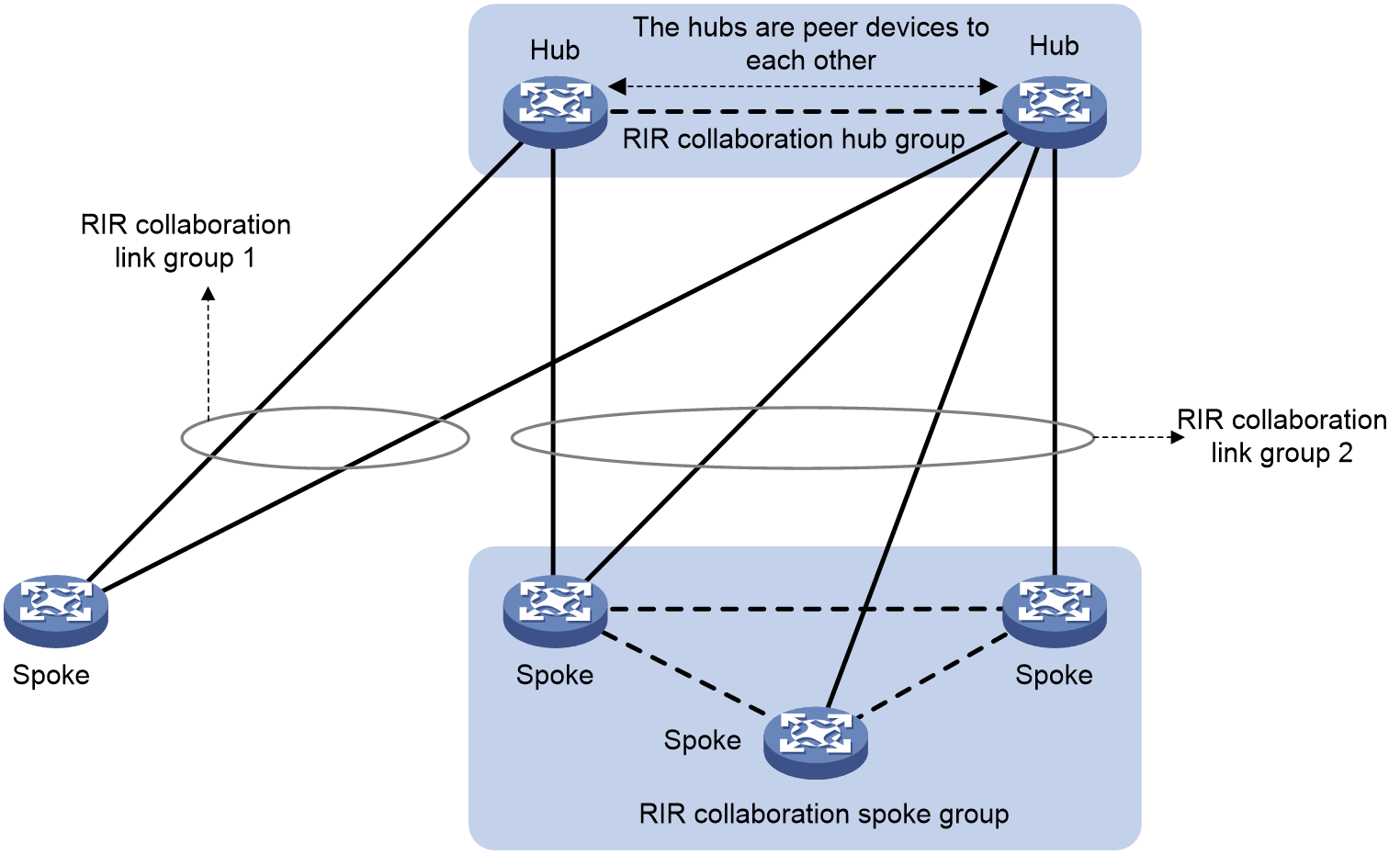
As shown in Figure 7, RIR collaboration has the following concepts:
· RIR collaboration device group—Contains a group of devices that collaboratively select links. Each pair of devices in an RIR collaboration device group are peer devices to each other. They share links for RIR.
Typically, devices in the same RIR collaboration device group are deployed in the same physical area, for example, the same equipment room or campus.
¡ A group of hubs can form an RIR collaboration hub group.
¡ A group of spokes can form an RIR collaboration spoke group.
An RIR collaboration device group acts as a logical device. The logical device can form a hub-spoke network with RIR collaboration device groups or physical devices.
· RIR collaboration link group—Contains a group of links that connect an RIR collaboration device group and another RIR collaboration device group or a physical device (hub or spoke). As shown in Figure 7, RIR collaboration link groups 1 and 2 connect the RIR collaboration hub group to a spoke and an RIR collaboration spoke group, respectively.
· Local packets and peer packets—In RIR collaboration, the packets firstly processed by the local device are called local packets and the packets firstly processed by the peer device are called peer packets. Devices in an RIR collaboration device group use different link selection policies to process local packets and peer packets. If a device does not belong to an RIR collaboration device group, all service packets received by the device are local packets.
Figure 7 RIR collaboration network structure
Working mechanism
The RIR collaboration mechanism is as follows:
1. After each pair of devices in an RIR collaboration device group establish RIR collaboration relationship, the device with a lower IP address acts as the client. The client initiates a TCP connection to the peer device.
2. Through TCP connections, a device synchronizes the configuration and status data of local links that meet the service requirements to its peer devices. The data does not include the link data synchronized from other devices in the same RIR collaboration device group. As a result, the devices in the RIR collaboration device group can obtain link information from one another, and can update link information in real time.
3. When a device in the RIR collaboration device group receives a service packet for a session, it handles the packets as shown in Table 2.
Table 2 Collaborative link selection policies
|
Packet condition |
Are routes available to forward the packet |
Collaborative link selection policies |
|
Local packet and received for the first time |
Yes |
If the optimal link information exists for the session, the local device forwards the packet according to the information. If no optimal link information exists for the session, the local device examines all links in the same flow template on the local device and peer devices. Then, the local device selects the most suitable link for the packet. · If the selected link is a link on the local device, the local device directly forwards the packet. · If the selected link is a link on a peer device, the local device forwards the packet to the peer device. |
|
Local packet and received for the first time |
No |
The local device selects a peer device in the same RIR collaboration device group and forwards the packet to the peer device. |
|
Local packet but not received for the first time |
Yes |
The packet is forwarded to a peer device, and then the peer device returns the packet back to the local device because it does not have a route to forward the packet. After the packet is returned back, the local device only examines the local links in order to find the most suitable link to forward the packet. The local device performs link reselection for the session every 60 seconds. This ensures that the traffic of the session can be switched to the peer device in time after the routes on the peer device recover. |
|
Local packet but not received for the first time |
No |
The local device selects a peer device to which it has never forwarded the traffic of the session and forwards the packet to the peer device. If no such a peer device is available, the local device discards the packet. |
|
Peer packet |
Yes |
If the optimal link information exists for the session, the local device forwards the packet according to the information. If no optimal link information exists for the session, the local device selects the most suitable link from the local links to forward the packet. |
|
Peer packet |
No |
The local device returns the packet back to the original peer device. |
RIR working mechanisms
Preparation
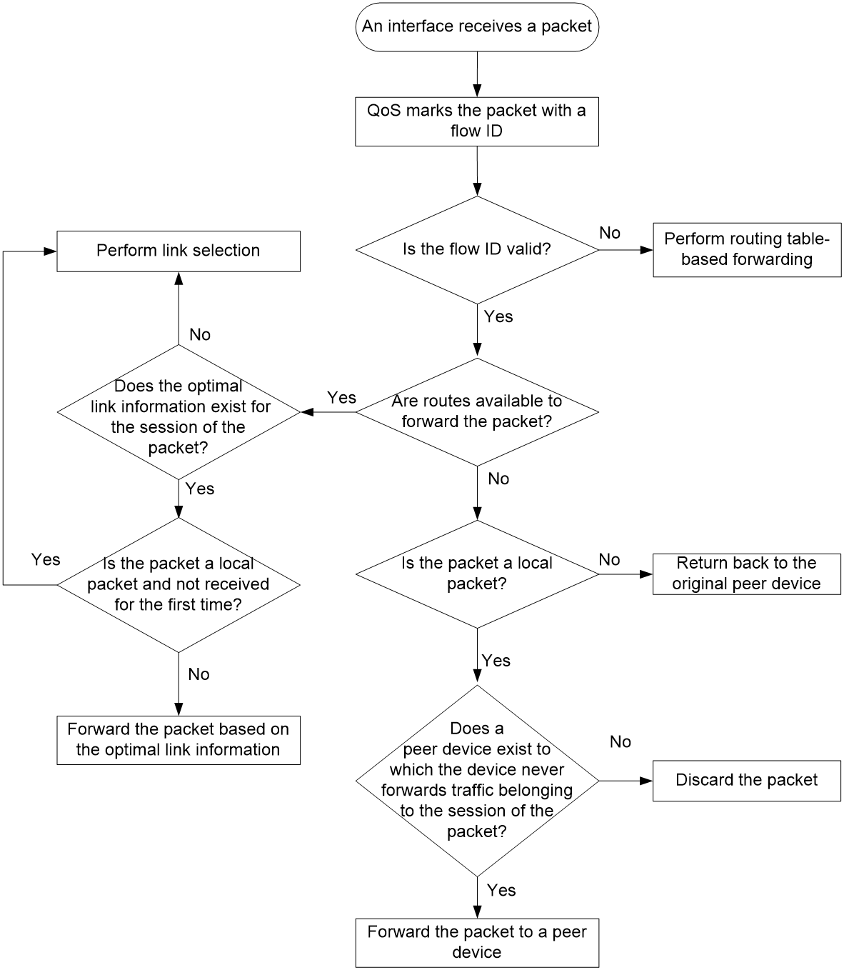
When the device receives a packet on an interface, it handles the packet as follows:
1. Uses QoS to mark the packet with a flow ID based on the quintuple and DSCP of the packet.
2. Identifies whether the flow ID of the packet is valid.
¡ If the flow ID is invalid, the device performs routing table-based forwarding for the packet.
¡ If the flow ID is valid, go to the next step.
3. Performs a routing table lookup to identify whether routes are available to forward the packet.
¡ If no route is available, the device identifies whether the packet is a local packet.
- If the packet is not a local packet, the device returns the packet back to the original peer device.
- If the packet is a local packet, the device selects a peer device to which it has never forwarded traffic for the packet's session and forwards the packet to the peer device. If no such a peer device is available, the device discards the packet.
¡ If routes are available, go to the next step.
4. Examines whether the optimal link information exists for the session of the packet.
¡ If the optimal link information exists, the device forwards the packet based on the information.
¡ If no optimal link information exists, the device performs link selection for the packet.
Figure 8 RIR preparation
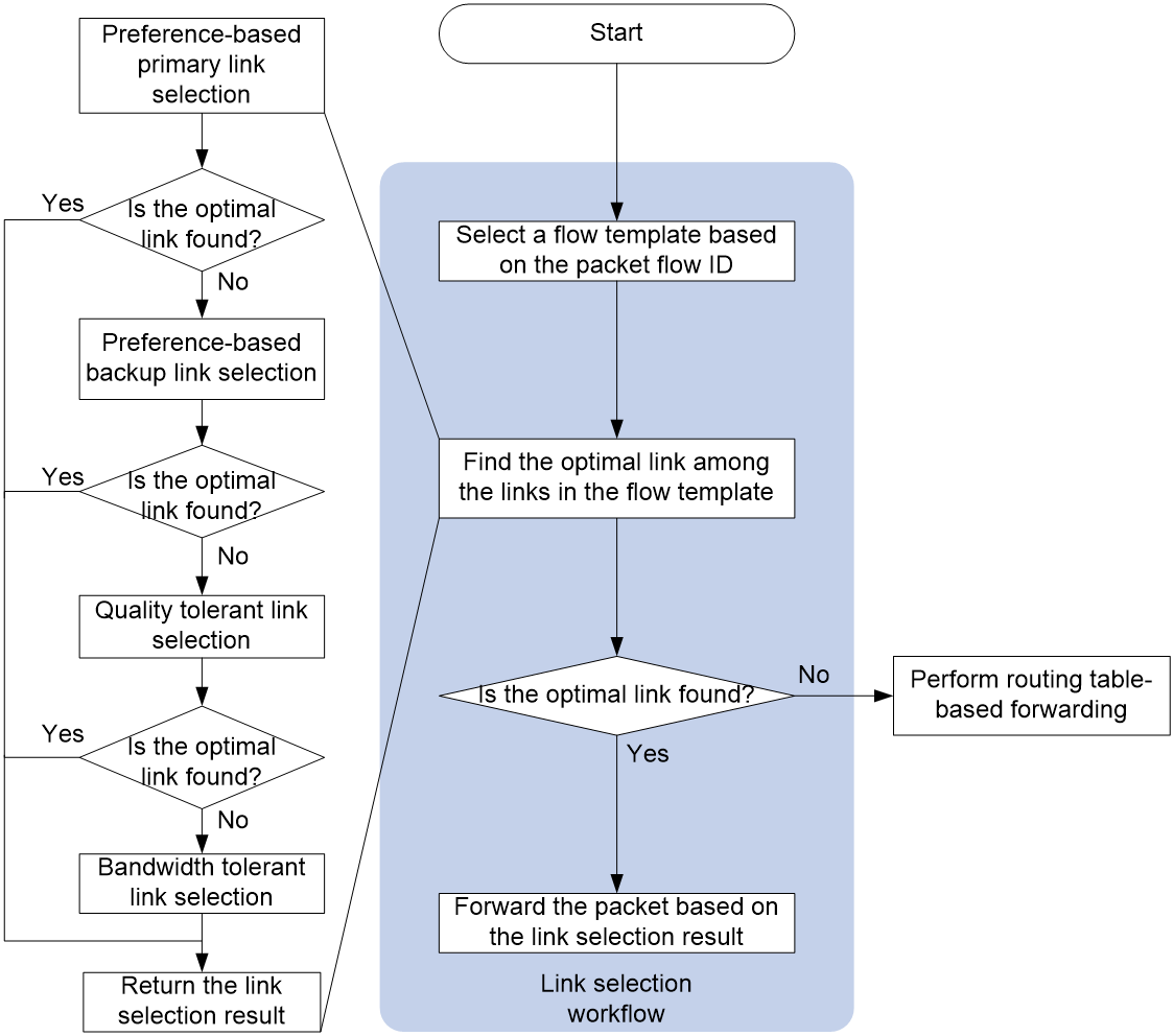
Link selection workflow summary
RIR uses the following workflow to select a link to forward a packet:
1. Selects the flow template that has the same flow ID as the packet.
2. Selects the most suitable link from the links in the flow template by using the following criteria in order:
a. Preference-based primary link selection.
b. Preference-based backup link selection.
c. Quality tolerant link selection.
d. Bandwidth tolerant link selection.
If the packet is a local packet and is received for the first time, the candidate links also include the links synchronized from RIR collaboration peer devices in the same flow template.
If the packet is a peer packet or the packet is a local packet but is not received for the first time, the candidate links only include links on the local device.
3. If a link is found suitable, RIR returns the link selection result and stops searching other links. If no link is found suitable for a criterion, RIR uses the next criterion to select links. If RIR fails to find a suitable link by using all criteria, it determines that no link is suitable and returns the link selection result.
4. If no suitable link is found, the device performs forwarding based on the routing table. If a suitable link is found, RIR forwards the packet based on the link selection result.
¡ If the most suitable link belongs to the local device, the device directly forwards the packet through the link.
¡ If the most suitable link belongs to a peer device in the RIR collaboration device group, the device forwards the packet to the peer device.
After finishing link selection, the device associates the quintuple of the packet with the most suitable link and records the association as the optimal link information for the session. The device forwards the subsequent packets of the same session based on the optimal link information. If no traffic is received for the session for a period of time, the device will delete the optimal link information.
Figure 9 RIR link selection workflow
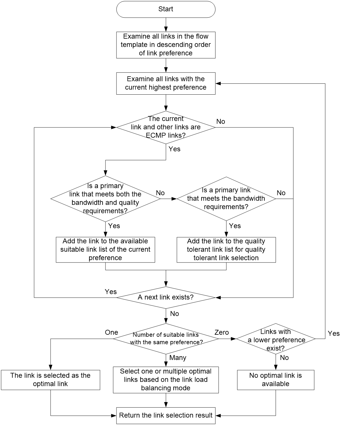
Preference-based primary link selection
RIR preferentially selects primary links that meet both the quality and bandwidth requirements for a service flow that matches a flow template. As shown in Figure 10, the device selects a primary link from the primary links in the flow template by examining the links in descending order of link preference. The device uses the following process to examine links with the same preference:
1. The device examines all links with the preference and identifies whether a link forms ECMP routes with other links. If a link forms ECMP routes with other links, the device further identifies whether the link is a primary link that meets both the quality and bandwidth requirements of the service.
¡ If yes, the device adds the link to the available suitable link list of that preference.
¡ If no, the device further identifies whether the link is a primary link that meets the bandwidth requirements of the service.
- If yes, the device adds the link to the quality tolerant link list for quality tolerant link selection. Then, the device continues to examine other links with the same preference.
- If no, the device continues to examine other links with the same preference.
If a link does not form ECMP routes with other links, the device continues to examine other links with the same preference.
2. When the device finishes examining all links with the preference, it identifies how many suitable links are available for the service flow.
¡ If only one suitable link is available, the device selects that link as the optimal link.
¡ If multiple suitable links are available, the device selects one or multiple optimal links from them based on the link load balancing mode. In a per-session load balancing mode, the device selects only one link as the optimal link of a session. In the per-packet load balancing mode, the device can select multiple links as the optimal links of a session.
¡ If no suitable link is available, the device examines the links that have a preference value lower than the links with the current preference.
If no primary links in the flow template are suitable, the device determines that no optimal primary link is found for the service flow.
For more information about identifying whether a link meets the quality requirements, see "Quality-based link selection." For more information about identifying whether a link meets the bandwidth requirements, see "Bandwidth-based link selection."
Figure 10 Preference-based primary link selection workflow
Preference-based backup link selection
If no primary link is suitable for a service flow, the device tries to find a backup link that meets both the quality and bandwidth requirements for the flow in the flow template. The link selection process is the same as that for selecting a primary link.
Quality tolerant link selection
If preference-based link selection fails to select a suitable link from both primary and backup links, the device performs quality tolerant link selection.
The links that meet the quality tolerant link selection criterion are those added to the quality tolerant link list during preference-based primary and backup link selection. These links do not meet the quality requirements of the service, but they meet the bandwidth requirements of the service. Quality tolerant link selection selects a link from the links that meet only the bandwidth requirements of the service.
If multiple quality tolerant links are available, the device selects one or multiple optimal links from them based on the link load balancing mode.
Bandwidth tolerant link selection
If quality tolerant link selection still cannot find a suitable link for a service flow, the device performs bandwidth tolerant link selection. Bandwidth tolerant link selection selects one link from ECMP routes in the flow template as the optimal link.
If multiple links are available, the device selects one or multiple optimal links from them based on the link load balancing mode.
Restrictions: Hardware compatibility with RIR
|
Hardware |
RIR compatibility |
|
MSR810, MSR810-W, MSR810-W-DB, MSR810-LM, MSR810-W-LM, MSR810-10-PoE, MSR810-LM-HK, MSR810-W-LM-HK, MSR810-LM-CNDE-SJK, MSR810-CNDE-SJK |
Yes |
|
MSR810-LMS, MSR810-LUS |
No |
|
MSR810-LMS-EA, MSR810-LME |
Yes |
|
MSR2600-6-X1, MSR2600-10-X1 |
Yes |
|
MSR 2630 |
Yes |
|
MSR3600-28, MSR3600-51 |
Yes |
|
MSR3600-28-SI, MSR3600-51-SI |
No |
|
MSR3600-28-X1, MSR3600-28-X1-DP, MSR3600-51-X1, MSR3600-51-X1-DP |
Yes |
|
MSR3610-I-DP, MSR3610-IE-DP, MSR3610-IE-ES, MSR3610-IE-EAD, MSR3610-I-IG, MSR3610-IE-IG |
Yes |
|
MSR3610-X1, MSR3610-X1-DP, MSR3610-X1-DC, MSR3610-X1-DP-DC |
Yes |
|
MSR 3610, MSR 3620, MSR 3620-DP, MSR 3640, MSR 3660 |
Yes |
|
MSR3610-G, MSR3620-G |
Yes |
|
Hardware |
RIR compatibility |
|
MSR810-W-WiNet, MSR810-LM-WiNet |
Yes |
|
MSR830-4LM-WiNet |
Yes |
|
MSR830-5BEI-WiNet, MSR830-6EI-WiNet, MSR830-10BEI-WiNet |
Yes |
|
MSR830-6BHI-WiNet, MSR830-10BHI-WiNet |
Yes |
|
MSR2600-6-WiNet, MSR2600-10-X1-WiNet |
Yes |
|
MSR2630-WiNet |
Yes |
|
MSR3600-28-WiNet |
Yes |
|
MSR3610-X1-WiNet |
Yes |
|
MSR3610-WiNet, MSR3620-10-WiNet, MSR3620-DP-WiNet, MSR3620-WiNet, MSR3660-WiNet |
Yes |
|
Hardware |
RIR compatibility |
|
MSR2630-XS |
Yes |
|
MSR3600-28-XS |
Yes |
|
MSR3610-XS |
Yes |
|
MSR3620-XS |
Yes |
|
MSR3610-I-XS |
Yes |
|
MSR3610-IE-XS |
Yes |
|
Hardware |
RIR compatibility |
|
MSR810-LM-GL |
Yes |
|
MSR810-W-LM-GL |
Yes |
|
MSR830-6EI-GL |
Yes |
|
MSR830-10EI-GL |
Yes |
|
MSR830-6HI-GL |
Yes |
|
MSR830-10HI-GL |
Yes |
|
MSR2600-6-X1-GL |
Yes |
|
MSR3600-28-SI-GL |
No |
RIR tasks at a glance
Spoke configuration tasks at a glance
To configure RIR on a spoke, perform the following tasks:
¡ Specifying an RIR client synchronization port
¡ (Optional.) Configuring NQA link connectivity probe parameters
¡ Configuring an NQA link quality operation
3. Configuring link attributes
¡ Assigning a link type and index to a VSI interface
¡ Configuring the link bandwidth of a VXLAN tunnel interface
¡ (Optional.) Configuring RIR backup links
4. Configuring a flow template
¡ Configuring a quality policy for the flow template
¡ (Optional.) Specifying the per-session expected bandwidth
¡ Specifying link preference values for links
5. (Optional.) Configuring the link load balancing mode
¡ Setting the per-session periodic link adjustment mode
¡ Setting the per-packet load balancing mode
By default, the per-session weight-based link selection mode is used.
6. (Optional.) Configuring flow priority-based traffic scheduling
7. (Optional.) Setting the link selection delay and link selection suppression period
8. Configuring a QoS policy to mark matching packets with a flow ID
¡ Creating a traffic class and defining packet match criteria
¡ Creating a traffic behavior and configuring a flow ID marking action
¡ Applying the QoS policy to an interface
9. (Optional.) Configuring RIR collaboration
a. Setting up RIR dedicated links between local and peer devices
b. Applying QoS policies to interfaces interconnecting local and peer devices
c. Assigning links to an RIR collaboration link group
d. Establishing RIR collaboration relationship for each pair of local and peer devices
e. Configuring RIR packet redirection
10. (Optional.) Enabling RIR logging
11. (Optional.) Configuring flow ID-based traffic rate statistics for tunnels
Hub configuration tasks at a glance
To configure RIR on a hub, perform the following tasks:
¡ Specifying an RIR server synchronization port
¡ (Optional.) Creating an SLA and an NQA link quality operation
3. Configuring link attributes
¡ Assigning a link type and index to a VSI interface
¡ Configuring the link bandwidth of a VXLAN tunnel interface
¡ (Optional.) Configuring RIR backup links
4. Configuring a flow template
¡ Configuring a quality policy for the flow template
¡ (Optional.) Specifying the per-session expected bandwidth
¡ Specifying link preference values for links
5. (Optional.) Configuring the link load balancing mode
¡ Setting the per-session periodic link adjustment mode
¡ Setting the per-packet load balancing mode
By default, the per-session weight-based link selection mode is used.
6. (Optional.) Configuring flow priority-based traffic scheduling
7. (Optional.) Setting the link selection delay and link selection suppression period
8. Configuring a QoS policy to mark matching packets with a flow ID
¡ Creating a traffic class and defining packet match criteria
¡ Creating a traffic behavior and configuring a flow ID marking action
¡ Applying the QoS policy to an interface
9. (Optional.) Configuring RIR collaboration
a. Setting up RIR dedicated links between local and peer devices
b. Applying QoS policies to interfaces interconnecting local and peer devices
c. Assigning links to an RIR collaboration link group
d. Establishing RIR collaboration relationship for each pair of local and peer devices
e. Configuring RIR packet redirection
10. (Optional.) Enabling RIR logging
11. (Optional.) Configuring flow ID-based traffic rate statistics for tunnels
Prerequisites for RIR configuration
Make sure the hub and each spoke have a minimum of two ECMP routes to reach each other.
Enabling the RIR process
1. Enter system view.
system-view
2. Enable the RIR process and enter RIR view.
rir
By default, the RIR process is disabled.
Configuring a spoke
Enabling the RIR client
About this task
To avoid NQA probes from occupying too many resources on a hub in a hub-spoke network, configure the hub as an RIR server and configure the spokes as RIR clients.
You can enable the RIR client globally or on an interface.
· Enabling the RIR client globally also enables the RIR client for all interfaces on the device. The interfaces can send link quality probe results for the RIR client.
· Enabling the RIR client on an interface allows only that interface to send link quality probe results for the RIR client.
Restrictions and guidelines
When you enable the RIR client, follow these restrictions and guidelines:
· In a VXLAN network, only tunnel interfaces support enabling the RIR client. The RIR client uses the tunnel interfaces to send link quality probe results.
· The RIR server and RIR client cannot be both enabled on the same interface.
· If the enabled role (RIR server or client) on an interface is different from the globally enabled role, the interface-specific role takes effect on that interface.
Procedure
1. Enter system view.
system-view
2. Enable the RIR client. Perform the following tasks as needed:
¡ Execute the following commands in sequence to enable the RIR client globally:
rir
client enable
¡ Execute the following commands in sequence to enable the RIR client on a VXLAN tunnel interface:
interface tunnel tunnel-number
rir role client
By default, the RIR client is disabled globally and on an interface.
Specifying an RIR client synchronization port
About this task
Perform this task to specify a port for an RIR client to synchronize link quality probe results to RIR servers.
Restrictions and guidelines
Specify the same synchronization port on the RIR client and server for successful synchronization of link quality probe results.
Procedure
1. Enter system view.
system-view
2. Enter RIR view.
rir
3. Specify a port for the RIR client to synchronize probe information to RIR servers.
probe sync-port port-number
By default, no port is specified for an RIR client to synchronize probe information to RIR servers.
Enabling the NQA client
About this task
An RIR client also acts as an NQA client. You must enable the NQA client on a spoke to ensure that NQA link connectivity probes and link quality probes can be performed correctly.
Procedure
1. Enter system view.
system-view
2. Enable the NQA client.
nqa agent enable
By default, the NQA client is disabled.
For more information about this command, see NQA commands in Network Management and Monitoring Command Reference.
Configuring NQA link connectivity probe parameters
About this task
An NQA client starts NQA link connectivity probes on all links configured on flow templates after RIR is enabled. A spoke (NQA client) performs consecutive probes at intervals as configured and waits for responses for the packets. If the client does not receive any responses when the probe packet timeout timer expires, a link connectivity issue exists.
In a VXLAN network, the NQA link connectivity probe targets are the VXLAN tunnel interfaces enabled with the RIR client.
A link connectivity probe packet uses the source IP address of a VXLAN tunnel as its source IP address and uses the tunnel destination IP address as its destination IP address.
Restrictions and guidelines
Setting a shorter probe interval obtains more precise probe results but requires more system resources.
Set a shorter probe packet timeout time if the requirement for link quality is high.
Procedure
1. Enter system view.
system-view
2. Enter RIR view.
rir
3. Configure NQA link connectivity probe parameters.
probe connect interval interval timeout timeout
By default, the NQA probe interval is 100 milliseconds and the NQA packet timeout time is 3000 milliseconds.
Configuring an NQA link quality operation
About this task
An NQA link quality operation allows a flow template to start UDP jitter probes based on the probe parameters in the operation in order to detect the quality of links.
You can configure a quality policy for a flow template to associate the flow template with an SLA and an NQA link quality operation. The device monitors the quality of links in the flow template based on the NQA link quality operation and compares the NQA probe results with the thresholds in the SLA. If all parameter values in the probe results of a link are lower than or equal to the thresholds in the SLA, the link is qualified for the flow.
To differentiate service flows that have different link quality requirements, associate the flow templates with NQA link quality operations that contain different probe parameter values. Two NQA link quality operations with different probe parameter values might offer different probe results for the same link.
In a VXLAN network, the NQA link quality probe targets are the VXLAN tunnel interfaces enabled with the RIR client.
A link quality probe packet uses the source IP address of a VXLAN tunnel as its source IP address and uses the tunnel destination IP address as its destination IP address.
Restrictions and guidelines
NQA link quality probes are used in conjunction with the NQA server and client features. For a spoke (NQA client) to perform NQA link quality probes, make sure UDP listening services have been configured on the NQA server.
Procedure
1. Enter system view.
system-view
2. Enter RIR view.
rir
3. Create an NQA link quality operation and enter its view.
nqa nqa-id
4. Configure NQA link quality probe parameters.
¡ Set the intervals at which the NQA client performs consecutive probes.
probe interval interval
By default, the NQA link quality probe interval is 100 milliseconds.
¡ Set the DSCP value of NQA link quality probe packets.
probe packet-dscp dscp-value
By default, the DSCP value of NQA link quality probe packets is 63.
¡ Set the number of NQA link quality probe packets sent per probe.
probe packet-number number
By default, 100 NQA link quality probe packets are sent per probe.
¡ Set the intervals at which NQA link quality probe packets are sent.
probe packet-interval interval
By default, NQA link quality probe packets are sent at intervals of 20 milliseconds.
¡ Set the timeout time for waiting for a response to an NQA link quality probe packet.
probe packet-timeout packet-timeout
By default, the timeout time is 3000 milliseconds.
¡ Specify a destination port for NQA link quality probes.
probe port port-number
By default, no destination port is specified for NQA link quality probes.
To correctly perform NQA link quality probes, the destination port number must be the same as the listening port on the NQA server.
Configuring an SLA
About this task
You can specify an SLA and NQA link quality operation for a flow template. The device monitors the quality of links in the flow template based on the NQA link quality operation and compares the NQA probe results with the thresholds in the SLA. The device selects only links that meet the quality requirements of the SLA for traffic that matches the flow template.
Perform this task to create an SLA and configure its link quality thresholds. Two SLAs might offer different quality results for the same NQA link quality operation.
Procedure
1. Enter system view.
system-view
2. Enter RIR view.
rir
3. Create an SLA and enter its view.
sla sla-id
4. Configure NQA link quality thresholds.
¡ Configure the link delay threshold.
delay threshold threshold-value
By default, the link delay threshold is 10 milliseconds.
¡ Configure the link jitter threshold.
jitter threshold threshold-value
By default, the link jitter threshold is 100 milliseconds.
¡ Configure the packet loss threshold.
packet-loss threshold threshold-value
By default, the packet loss threshold is 100‰.
Configuring a hub
Enabling the RIR server
About this task
To avoid NQA probes from occupying too many resources on a hub in a hub-spoke network, configure the hub as an RIR server and configure the spokes as RIR clients.
You can enable the RIR server globally or on an interface.
· Enabling the RIR server globally also enables the RIR server for all interfaces on the device. The interfaces can receive link quality probe results synchronized from RIR clients.
· Enabling the RIR server on an interface allows only that interface to receive link quality probe results synchronized from RIR clients.
Restrictions and guidelines
When you enable the RIR server, follow these restrictions and guidelines:
· In a VXLAN network, only tunnel interfaces support enabling the RIR server. The RIR server uses the tunnel interfaces to receive link quality probe results synchronized from RIR clients.
· The RIR server and RIR client cannot be both enabled on the same interface.
· If the enabled role (RIR server or client) on an interface is different from the globally enabled role, the interface-specific role takes effect on that interface.
Procedure
1. Enter system view.
system-view
2. Enable the RIR server. Perform the following tasks as needed:
¡ Execute the following commands in sequence to enable the RIR server globally:
rir
server enable
¡ Execute the following commands in sequence to enable the RIR server on a VXLAN tunnel interface:
interface tunnel tunnel-number
rir role server
By default, the RIR server is disabled globally and on an interface.
Specifying an RIR server synchronization port
About this task
Perform this task to specify a port for an RIR server to receive link quality probe results synchronized from RIR clients.
Restrictions and guidelines
Specify the same synchronization port on the RIR client and server for successful synchronization of link quality probe results.
Procedure
1. Enter system view.
system-view
2. Enter RIR view.
rir
3. Specify a port for receiving probe information synchronized from RIR clients.
probe sync-port port-number
By default, no port is specified for receiving probe information synchronized from RIR clients.
Configuring the NQA server
About this task
A hub that acts as an RIR server also acts as an NQA server. To ensure that NQA link connectivity probes can be performed correctly, you must enable the NQA server on the hub. To ensure that NQA link quality probes can be performed correctly, configure UDP listening services.
Restrictions and guidelines
The listening port specified on the hub (NQA server) must be the same as the destination port number specified in NQA link quality operations on the spokes (NQA clients). In addition, make sure the port is not used by any other services.
Procedure
1. Enter system view.
system-view
2. Enable the NQA server.
nqa server enable
By default, the NQA server is disabled.
For more information about this command, see NQA commands in Network Management and Monitoring Command Reference.
3. Configure a UDP listening service for the NQA server to listen to a port on an IP address.
nqa server udp-echo ip-address port-number [ vpn-instance vpn-instance-name ] [ tos tos ]
For more information about this command, see NQA commands in Network Management and Monitoring Command Reference.
Creating an SLA and an NQA link quality operation
About this task
When you configure the quality policy of a flow template on a hub, you must specify an SLA and an NQA link quality operation. Perform this task to create the SLA and NQA link quality operation specified in the quality policy. On the hub, you do not need to configure the parameters in the SLA and NQA link quality operation. If you configure these parameters, the configuration does not take effect. For more information about quality policy configuration, see "Configuring a quality policy for the flow template."
Restrictions and guidelines
If you do not plan to configure the quality policy of a flow template on a hub, you do not need to create an SLA and NQA link quality operation.
The hub and spoke can have different SLA and NQA link quality operation settings in the quality policy of the same flow template. The difference does not affect the execution and application of the quality policy. As a best practice to identify the quality policy, configure the same SLA and NQA link quality operation on the hub and spoke.
Procedure
1. Enter system view.
system-view
2. Enter RIR view.
rir
3. Create an SLA and enter its view.
sla sla-id
4. Return to RIR view.
quit
5. Create an NQA link quality operation and enter its view.
nqa nqa-id
Configuring link attributes
Assigning a link type and index to a VSI interface
About this task
The link type and link index together uniquely identify a link between a hub and a spoke. For a flow template to use a link, you must assign a link type and index to the link. Perform this task to configure the link type as 4G, Internet, MPLS, or MSTP. The link type only marks the network type of the link and it does not affect packet encapsulation.
VXLAN-based RIR allows a hub and a spoke to have only one VXLAN tunnel for a VSI interface (a VXLAN). By assigning a link type and index to the VSI interface, RIR can identify the VXLAN tunnel between the hub and spoke.
A VSI interface on a hub (or spoke) can have a VXLAN tunnel to each spoke (or hub). The VXLAN tunnels of the same VSI interface are assigned the same link type and link index.
Restrictions and guidelines
Only 4G, Internet, MPLS, and MSTP link types are supported.
The link type is used only for identifying links, and it does not affect packet encapsulation.
A VSI interface can be associated only with one link type.
You must assign different link indexes to the same type of links on different VSI interfaces.
Procedure
1. Enter system view.
system-view
2. Enter VSI interface view.
interface vsi-interface vsi-interface-id
3. Assign a link type and index to the VSI interface.
rir link-type { 4g | internet | mpls | mstp } index link-index
By default, no link type or index is assigned to a VSI interface.
Configuring the link bandwidth of a VXLAN tunnel interface
1. Enter system view.
system-view
2. Enter VXLAN tunnel interface view.
interface tunnel tunnel-number
3. Configure the expected link bandwidth of the VXLAN tunnel interface.
bandwidth bandwidth-value
The default expected bandwidth (in kbps) is the interface maximum rate divided by 1000.
The expected bandwidth is an informational parameter used only by higher-layer protocols for calculation. You cannot adjust the actual bandwidth of an interface by using this command.
For more information about this command, see tunneling commands in Layer 3—IP Services Command Reference.
Configuring RIR backup links
About this task
The links between a spoke and a primary hub are typically primary links, and the links between a spoke and a backup hub are typically backup links. RIR selects qualified primary links prior to qualified backup links.
In a VXLAN network, the links (VXLAN tunnels) that are assigned link preference values are primary links by default. If you configure a VXLAN tunnel as an RIR backup tunnel, RIR uses the VXLAN tunnel as an RIR backup link.
Restrictions and guidelines
Configure VXLAN tunnels as backup links depending on the network requirements. You can configure a VXLAN tunnel between a spoke and a primary hub as a backup link.
Procedure
1. Enter system view.
system-view
2. Enter VXLAN tunnel interface view.
interface tunnel number
3. Configure the tunnel as an RIR backup tunnel.
rir backup
By default, a tunnel is an RIR primary tunnel.
Configuring a flow template
About flow template configuration
Configure a flow template to determine the link selection policies for a type of service flow.
Creating a flow template
About this task
To define link selection policies for a type of service flow, you can create a flow template and configure link selection policies in the flow template. By marking the type of service flow with the flow ID of the flow template, the device can use the link selection policies in the flow template to select links for that type of service flow.
Procedure
1. Enter system view.
system-view
2. Enter RIR view.
rir
3. Create a flow template and enter its view.
flow flow-id
Configuring a quality policy for the flow template
About this task
If you configure the quality policy of a flow template on a hub, the hub performs link quality detection based on the link quality probe results synchronized from spokes. If you do not configure the quality policy on the spokes for the same flow template, the hub cannot obtain link quality probe results from any spokes. Because the hub does not perform link quality probe on its own, it determines that all links in the flow template fail quality detection.
If you do not configure the quality policy of a flow template on a hub, the hub determines that all links in the flow template meet the service quality requirements.
Procedure
1. Enter system view.
system-view
2. Enter RIR view.
rir
3. Enter flow template view.
flow flow-id
4. Configure a quality policy for the flow template.
quality-policy sla sla-id nqa nqa-id
By default, no quality policy is configured for a flow template.
The specified SLA and NQA link quality operation must already exist.
Specifying the per-session expected bandwidth
About this task
To select a link for traffic of a session, a device first performs bandwidth detection based on the per-session expected bandwidth in the flow template to which the session belongs. If the used bandwidth plus the per-session expected bandwidth of a candidate link is less than 80% of its total bandwidth, the current available bandwidth of the candidate link meets the session bandwidth requirements. The link passes the bandwidth detection.
The per-session expected bandwidth is not the actual bandwidth of a session. It is only a value estimated based on the user services.
Procedure
1. Enter system view.
system-view
2. Enter RIR view.
rir
3. Enter flow template view.
flow flow-id
4. Specify the per-session expected bandwidth.
expect-bandwidth bandwidth
By default, the per-session expected bandwidth is 0 kbps.
Specifying link preference values for links
About this task
RIR preferentially selects links with higher preference for a type of service flow.
VXLAN-based RIR supports assigning a link preference to a type of links with a specific link index in flow template view. The link type and link index identify links on a VSI interface. As VXLAN-based RIR allows a hub and spoke to have only one VXLAN tunnel for a VSI interface, the link preference configured on the VSI interface is the link preference of the VXLAN tunnel between the hub and spoke.
Restrictions and guidelines
You can assign the same link preference value to links with different link types and indexes in the same flow template.
Procedure
1. Enter system view.
system-view
2. Enter RIR view.
rir
3. Enter flow template view.
flow flow-id
4. Configure a link preference for the specified type of links with the specified link index.
path link-type { 4g | internet | mpls | mstp } index link-index preference preference
By default, no link preference is configured for a type of links with a specific link index in a flow template.
Configuring the link load balancing mode
Restrictions and guidelines for link load balancing mode configuration
For a flow template, the per-packet load balancing mode takes precedence over the global per-session periodic link adjustment mode. If the per-packet load balancing mode is not enabled for a flow template, the flow template uses the global link load balancing mode.
Setting the per-session periodic link adjustment mode
1. Enter system view.
system-view
2. Enter RIR view.
rir
3. Set the link load balancing mode to the per-session periodic link adjustment mode.
load-balance per-session periodic-adjust enable
By default, the link load balancing mode is per-session weight-based link selection mode.
4. Set the adjustment interval for the per-session periodic link adjustment mode.
load-balance per-session periodic-adjust adjust-interval interval-value
By default, the adjustment interval for the per-session periodic link adjustment mode is 30 seconds.
5. Set the periodic adjustment thresholds in per-session periodic link adjustment mode.
load-balance per-session periodic-adjust threshold upper upper-threshold-value lower lower-threshold-value
By default, the periodic adjustment upper threshold is 50% and the periodic adjustment lower threshold is 20%.
The periodic adjustment upper threshold must be greater than or equal to the periodic adjustment lower threshold.
Setting the per-packet load balancing mode
Restrictions and guidelines
Because packets of the same session are distributed to multiple links, the receiver might receive out-of-order packets. As a best practice, do not enable per-packet load balancing for order-sensitive services (except the services that use protocols to maintain a correct packet order, for example, TCP).
Procedure
1. Enter system view.
system-view
2. Enter RIR view.
rir
3. Enter flow template view.
flow flow-id
4. Set the link load balancing mode to the per-packet mode.
load-balance per-packet enable
By default, the RIR global link load balancing mode applies.
Configuring flow priority-based traffic scheduling
About this task
To ensure that services with higher priority preferentially use link resources, enable flow priority-based traffic scheduling.
The priority of a flow that matches a flow template is determined by the ID of the SLA associated with that flow template. The greater the SLA ID is, the higher the flow priority. To specify an SLA for a flow template, use the quality-policy command. If the command is not configured in a flow template, flows that match the flow template have the lowest priority.
If flow priority-based traffic scheduling is enabled, traffic scheduling is triggered when the bandwidth usage of a link exceeds the upper threshold. The scheduling might be last for several scheduling periods. Within each scheduling period, RIR redistributes the current lowest priority flow on this link to other links. The scheduling does not stop until the bandwidth usage of all links for the current lowest priority flow is below the lower threshold or only the highest priority flow is left on this link.
Procedure
1. Enter system view.
system-view
2. Enter RIR view.
rir
3. Enable flow priority-based traffic scheduling.
flow priority-based-schedule enable
By default, flow priority-based traffic scheduling is disabled.
4. Set the scheduling period for flow priority-based traffic scheduling.
flow priority-based-schedule schedule-period schedule-period-value
By default, the scheduling period for flow priority-based traffic scheduling is 30 seconds.
5. Set the bandwidth usage thresholds for flow priority-based traffic scheduling.
flow priority-based-schedule bandwidth-threshold upper upper-threshold lower lower-threshold
By default, the bandwidth usage upper threshold is 90% and the bandwidth usage lower threshold is 20%.
The upper threshold must be greater than or equal to the lower threshold.
Setting the link selection delay and link selection suppression period
1. Enter system view.
system-view
2. Enter RIR view.
rir
3. Set the link selection delay.
link-select delay delay
By default, the link selection delay is 60 seconds.
4. Set the link selection suppression period.
link-select suppress-period period-value
By default, no link selection suppression period is configured. The device does not start the link selection suppression period after a link selection.
As a best practice, set the link selection suppression period to a multiple of the link selection delay time. Make sure the suppression period is at least double of the link selection delay time.
Configuring a QoS policy to mark matching packets with a flow ID
About configuring a QoS policy to mark matching packets with a flow ID
Apply a QoS policy to an interface to mark matching packets on the interface with a flow ID. RIR processes packets marked with a flow ID based on the flow template that uses the flow ID. For more information about QoS marking, see QoS overview, QoS policies, and marking configuration in ACL and QoS Configuration Guide.
Creating a traffic class and defining packet match criteria
1. Enter system view.
system-view
2. Create a traffic class and enter its view.
traffic classifier classifier-name [ operator { and | or } ]
3. Define packet match criteria, including the quintuple and DSCP.
if-match [ not ] match-criteria
By default, no packet match criteria are defined.
Creating a traffic behavior and configuring a flow ID marking action
1. Enter system view.
system-view
2. Create a traffic behavior and enter its view.
traffic behavior behavior-name
3. Configure the traffic behavior to mark matching traffic with the specified flow ID.
remark flow-id flow-id
By default, no flow ID marking action is configured.
Configuring a QoS policy
1. Enter system view.
system-view
2. Create a QoS policy and enter its view.
qos policy policy-name
3. Associate the traffic behavior with the traffic class in the QoS policy.
classifier classifier-name behavior behavior-name
By default, no traffic behavior is associated with a traffic class.
Applying the QoS policy to an interface
1. Enter system view.
system-view
2. Enter interface view.
interface interface-type interface-number
3. Apply the QoS policy to the inbound direction of the interface.
qos apply policy policy-name inbound
By default, no QoS policy is applied to an interface.
Configuring RIR collaboration
Restrictions and guidelines for RIR collaboration configuration
All devices that form an RIR collaboration device group must have independent RIR capabilities. They must mark the same type of service traffic with the same flow ID.
Perform the RIR collaboration tasks in this section on both the local and peer devices in an RIR collaboration device group.
Setting up RIR dedicated links between local and peer devices
Use RIR dedicated links to ensure that packets can be correctly forwarded between local and peer devices. You can configure direct routes or GRE tunnels as dedicated links as follows:
· For directly-connected peer devices, you can configure multiple physical interfaces or subinterfaces on the devices. The interfaces or subinterfaces will generate direct routes for packets in the public network and each VPN instance. For more information, see Ethernet interface configuration in Interface Configuration Guide.
· For indirectly-connected peer devices, manually configure GRE tunnels between them for packets in the public network and each VPN instance. For more information about GRE configuration, see Layer 3—IP Services Configuration Guide.
Applying QoS policies to interfaces interconnecting local and peer devices
Outgoing packets do not carry the flow ID marked in the RIR process. To mark a flow ID for received packets, apply a QoS policy to the interfaces interconnecting the local and peer devices. For more information, see "Configuring a QoS policy to mark matching packets with a flow ID."
Assigning links to an RIR collaboration link group
About this task
The local device can discover and select links synchronized from peer devices only after the links are assigned to an RIR collaboration link group. In the RIR collaboration link group, both local links and links synchronized from peer devices have the same destination.
Restrictions and guidelines
In an RIR collaboration device group, make sure all links to the same device or RIR collaboration device group are assigned to the same RIR collaboration link group.
In an RIR collaboration device group, make sure the links to different devices or RIR collaboration device groups are assigned to different RIR collaboration link groups.
In different RIR collaboration device groups, the links to the same device or RIR collaboration device group can be assigned to the same RIR collaboration link group. As a best practice to identify links, assign the links to different RIR collaboration link groups.
Procedure
1. Enter system view.
system-view
2. Enter VXLAN tunnel interface view.
interface tunnel number
3. Assign the VXLAN tunnel to an RIR collaboration link group.
rir collaboration-link-group group-id
By default, a VXLAN tunnel belongs to RIR collaboration link group 0.
Establishing RIR collaboration relationship for each pair of local and peer devices
About this task
Each pair of devices in an RIR collaboration device group must establish RIR collaboration relationship with each other for link data synchronization. After a pair of devices establish RIR collaboration relationship, the device with a lower IP address acts as the client to initiate a TCP connection to the other device. Through the TCP connection, the local device can synchronize the configuration and status data of links that meet the service requirements to the peer device. The data does not include the link data synchronized from other devices in the same RIR collaboration device group.
Restrictions and guidelines
The local and peer IP addresses used to establish RIR collaboration relationship must belong to the public network or the same VPN instance.
A pair of RIR collaboration devices can establish only one TCP connection to synchronize link data.
Procedure
1. Enter system view.
system-view
2. Enter RIR view.
rir
3. Enable the local device to establish RIR collaboration relationship with a peer device.
collaboration peer [ vpn-instance vpn-instance-name ] peer-ipv4-address local local-ipv4-address sync-port port-number
By default, the local device does not establish RIR collaboration relationship with any device.
Configuring RIR packet redirection
About this task
For the local device to select links from a peer device, you must configure RIR packet redirection. Perform this task to specify the redirect IP address for packets redirected to the peer device on the public network or a VPN instance. When the local device selects links from the peer device to forward packets on the public network or a VPN instance, it performs the following operations:
1. Looks up the routing table of the public network or VPN instance based on the redirect IP address.
2. Forwards the packets to the peer device through the RIR dedicated link.
Procedure
1. Enter system view.
system-view
2. Enter RIR view.
rir
3. Specify the IP address to which the local device redirects packets forwarded to an RIR collaboration peer.
collaboration peer [ vpn-instance vpn-instance-name ] peer-ipv4-address redirect [ vpn-instance redirect-vpn-instance-name ] redirect-ipv4-address
By default, no IP address is specified for the local device to redirect packets forwarded to an RIR collaboration peer.
The vpn-instance vpn-instance-name option specifies the VPN instance on which the local and peer devices establish RIR collaboration relationship. The vpn-instance redirect-vpn-instance-name option specifies a redirect VPN instance. When the local device selects a link from a peer device for forwarding traffic in the redirect VPN instance, the local device redirects the packets to the redirect IPv4 address.
Enabling RIR logging
About this task
RIR logs record events occurred during the RIR process, such as link selection and reselection, quality change, bandwidth change, configuration change, and link fault events. The logs help the administrator analyze, maintain, and adjust the RIR network.
RIR logs are flow logs. To output RIR logs, you must also configure flow log features. For more information about flow logs, see Network Management and Monitoring Configuration Guide.
Procedure
1. Enter system view.
system-view
2. Enter RIR view.
rir
3. Enable RIR logging.
log enable
By default, RIR logging is disabled.
Configuring flow ID-based traffic rate statistics for tunnels
About this task
This feature enables the device to periodically collect traffic rate statistics for tunnels on a flow ID basis.
Procedure
1. Enter system view.
system-view
2. Enable flow ID-based traffic rate statistics for tunnels.
tunnel flow-statistics enable
By default, flow ID-based traffic rate statistics for tunnels is disabled.
3. (Optional.) Set the intervals at which the device collects flow ID-based traffic rate statistics for tunnels.
tunnel flow-statistics interval interval
By default, the device collects flow ID-based traffic rate statistics for tunnels at intervals of 300 seconds.
Display and maintenance commands for RIR
Execute display commands in any view and reset commands in user view.
|
Task |
Command |
|
Display flow ID-based traffic rate statistics for tunnels. |
display tunnel flow-statistics [ flow flow-id [ interface tunnel number ] ] |
|
Clear flow ID-based traffic rate statistics for tunnels. |
reset tunnel flow-statistics [ flow flow-id [ interface tunnel number ] ] |
RIR configuration examples
Example: Configuring RIR in a VXLAN-based hub-spoke network
Network configuration
As shown in Figure 11:
· Router A and Router B are hubs, and Router C is a spoke.
· Configure Router A, Router B, and Router C as VXLAN VTEPs. Router A and Router B each have two VXLAN tunnels to reach Router C.
· Configure OSPF on the transport network devices to make sure Router A, Router B, and Router C have routes to reach one another.
· Create VSI-interface 1 and VSI-interface 2 on Router A, Router B, and Router C and associate the VSI interfaces with VSIs (VXLANs) on the routers. Make sure a VSI interface is associated only with one VXLAN tunnel for each pair of routers.
· Configure Router A, Router B, and Router C as distributed VXLAN IP gateways and configure BGP on Router A, Router B, Router C, Router E, Router F, and Router G. Make sure Router A, Router B, and Router C each have a minimum of two ECMP routes to reach one another and the output interfaces of the routes are the VSI interfaces.
Configure RIR as follows:
· Configure flow template 1 and flow template 2 for RIR to select the most suitable links for packets with a DSCP value of 1 and packets with a DSCP value of 2, respectively.
· When the hubs perform link selection, they do not perform quality detection. When the spoke performs link selection, it performs quality detection.
· The per-session weight-based link selection mode is used, which is the default mode. No configuration is required.
· Assign the same preference value to the two links in each flow template on the hubs. The links will load share traffic when they both meet the service requirements.
· Assign different preference values to the two links in each flow template on the spoke. The spoke will preferentially select the link with a higher preference to forward traffic.
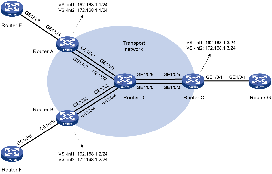
Table 3 Interface and IP address assignment
|
Device |
Interface |
IP address |
Device |
Interface |
IP address |
|
Router A |
GE1/0/1 |
1.1.1.1/24 |
Router D |
GE1/0/1 |
1.1.1.2/24 |
|
|
GE1/0/2 |
2.1.1.1/24 |
|
GE1/0/2 |
2.1.1.2/24 |
|
|
GE1/0/3 |
30.1.1.1/24 |
|
GE1/0/3 |
3.1.1.2/24 |
|
Router B |
GE1/0/3 |
3.1.1.1/24 |
|
GE1/0/4 |
4.1.1.2/24 |
|
|
GE1/0/4 |
4.1.1.1/24 |
|
GE1/0/5 |
5.1.1.2/24 |
|
|
GE1/0/5 |
50.1.1.1/24 |
|
GE1/0/6 |
6.1.1.2/24 |
|
Router C |
GE1/0/5 |
5.1.1.1/24 |
Router E |
GE1/0/3 |
30.1.1.2/24 |
|
|
GE1/0/6 |
6.1.1.1/24 |
Router F |
GE1/0/5 |
50.1.1.2/24 |
|
|
GE1/0/1 |
10.1.1.1/24 |
Router G |
GE1/0/1 |
10.1.1.2/24 |
Prerequisites
Configure IP addresses and subnet masks for the interfaces as shown in Figure 11.
Procedure
1. Configure OSPF on transport network devices:
# Configure Router A.
<RouterA> system-view
[RouterA] ospf 1
[RouterA-ospf-1] area 0
[RouterA-ospf-1-area-0.0.0.0] network 1.1.1.0 0.0.0.255
[RouterA-ospf-1-area-0.0.0.0] quit
[RouterA-ospf-1] quit
[RouterA] ospf 2
[RouterA-ospf-2] area 0
[RouterA-ospf-2-area-0.0.0.0] network 2.1.1.0 0.0.0.255
[RouterA-ospf-2-area-0.0.0.0] quit
[RouterA-ospf-2] quit
# Configure Router B.
<RouterB> system-view
[RouterB] ospf 1
[RouterB-ospf-1] area 0
[RouterB-ospf-1-area-0.0.0.0] network 3.1.1.0 0.0.0.255
[RouterB-ospf-1-area-0.0.0.0] quit
[RouterB-ospf-1] quit
[RouterB] ospf 2
[RouterB-ospf-2] area 0
[RouterB-ospf-2-area-0.0.0.0] network 4.1.1.0 0.0.0.255
[RouterB-ospf-2-area-0.0.0.0] quit
[RouterB-ospf-2] quit
# Configure Router C.
<RouterC> system-view
[RouterC] ospf 1
[RouterC-ospf-1] area 0
[RouterC-ospf-1-area-0.0.0.0] network 5.1.1.0 0.0.0.255
[RouterC-ospf-1-area-0.0.0.0] quit
[RouterC-ospf-1] quit
[RouterC] ospf 2
[RouterC-ospf-2] area 0
[RouterC-ospf-2-area-0.0.0.0] network 6.1.1.0 0.0.0.255
[RouterC-ospf-2-area-0.0.0.0] quit
[RouterC-ospf-2] quit
# Configure Router D.
<RouterD> system-view
[RouterD] ospf 1
[RouterD-ospf-1] area 0
[RouterD-ospf-1-area-0.0.0.0] network 1.1.1.0 0.0.0.255
[RouterD-ospf-1-area-0.0.0.0] network 3.1.1.0 0.0.0.255
[RouterD-ospf-1-area-0.0.0.0] network 5.1.1.0 0.0.0.255
[RouterD-ospf-1-area-0.0.0.0] quit
[RouterD-ospf-1] quit
[RouterD] ospf 2
[RouterD-ospf-2] area 0
[RouterD-ospf-2-area-0.0.0.0] network 2.1.1.0 0.0.0.255
[RouterD-ospf-2-area-0.0.0.0] network 4.1.1.0 0.0.0.255
[RouterD-ospf-2-area-0.0.0.0] network 6.1.1.0 0.0.0.255
[RouterD-ospf-2-area-0.0.0.0] quit
[RouterD-ospf-2] quit
2. Configure VXLAN settings on transport network devices:
¡ Configure Router A:
# Enable L2VPN.
[RouterA] l2vpn enable
# Create VSI vpna and VXLAN 90.
[RouterA] vsi vpna
[RouterA-vsi-vpna] vxlan 90
[RouterA-vsi-vpna-vxlan-90] quit
[RouterA-vsi-vpna] quit
# Create VSI vpnb and VXLAN 70.
[RouterA] vsi vpnb
[RouterA-vsi-vpnb] vxlan 70
[RouterA-vsi-vpnb-vxlan-70] quit
[RouterA-vsi-vpnb] quit
# Create a VXLAN tunnel to Router C. The tunnel interface name is Tunnel 1.
[RouterA] interface tunnel 1 mode vxlan
[RouterA-Tunnel1] source 1.1.1.1
[RouterA-Tunnel1] destination 5.1.1.1
[RouterA-Tunnel1] quit
# Create a VXLAN tunnel to Router C. The tunnel interface name is Tunnel 2.
[RouterA] interface tunnel 2 mode vxlan
[RouterA-Tunnel2] source 2.1.1.1
[RouterA-Tunnel2] destination 6.1.1.1
[RouterA-Tunnel2] quit
# Assign Tunnel 1 to VXLAN 90.
[RouterA] vsi vpna
[RouterA-vsi-vpna] vxlan 90
[RouterA-vsi-vpna-vxlan-90] tunnel 1
[RouterA-vsi-vpna-vxlan-90] quit
[RouterA-vsi-vpna] quit
# Assign Tunnel 2 to VXLAN 70.
[RouterA] vsi vpnb
[RouterA-vsi-vpnb] vxlan 70
[RouterA-vsi-vpnb-vxlan-70] tunnel 2
[RouterA-vsi-vpnb-vxlan-70] quit
[RouterA-vsi-vpnb] quit
# Create VSI-interface 1, assign it an IP address, specify the VSI interface as a distributed gateway, and enable local proxy ARP on the interface.
[RouterA] interface vsi-interface 1
[RouterA-Vsi-interface1] ip address 192.168.1.1 255.255.255.0
[RouterA-Vsi-interface1] distributed-gateway local
[RouterA-Vsi-interface1] local-proxy-arp enable
[RouterA-Vsi-interface1] quit
# Create VSI-interface 2, assign it an IP address, specify the VSI interface as a distributed gateway, and enable local proxy ARP on the interface.
[RouterA] interface vsi-interface 2
[RouterA-Vsi-interface2] ip address 172.168.1.1 255.255.255.0
[RouterA-Vsi-interface2] distributed-gateway local
[RouterA-Vsi-interface2] local-proxy-arp enable
[RouterA-Vsi-interface2] quit
# Specify VSI-interface 1 as the gateway interface for VSI vpna. Assign subnet 192.168.1.0/24 to the VSI.
[RouterA] vsi vpna
[RouterA-vsi-vpna] gateway vsi-interface 1
[RouterA-vsi-vpna] gateway subnet 192.168.1.0 0.0.0.255
[RouterA-vsi-vpna] quit
# Specify VSI-interface 2 as the gateway interface for VSI vpnb. Assign subnet 172.168.1.0/24 to the VSI.
[RouterA] vsi vpnb
[RouterA-vsi-vpnb] gateway vsi-interface 2
[RouterA-vsi-vpnb] gateway subnet 172.168.1.0 0.0.0.255
[RouterA-vsi-vpnb] quit
¡ Configure Router B:
# Enable L2VPN.
[RouterB] l2vpn enable
# Create VSI vpna and VXLAN 90.
[RouterB] vsi vpna
[RouterB-vsi-vpna] vxlan 90
[RouterB-vsi-vpna-vxlan-90] quit
[RouterB-vsi-vpna] quit
# Create VSI vpnb and VXLAN 70.
[RouterB] vsi vpnb
[RouterB-vsi-vpnb] vxlan 70
[RouterB-vsi-vpnb-vxlan-70] quit
[RouterB-vsi-vpnb] quit
# Create a VXLAN tunnel to Router C. The tunnel interface name is Tunnel 3.
[RouterB] interface tunnel 3 mode vxlan
[RouterB-Tunnel3] source 3.1.1.1
[RouterB-Tunnel3] destination 5.1.1.1
[RouterB-Tunnel3] quit
# Create a VXLAN tunnel to Router C. The tunnel interface name is Tunnel 4.
[RouterB] interface tunnel 4 mode vxlan
[RouterB-Tunnel4] source 4.1.1.1
[RouterB-Tunnel4] destination 6.1.1.1
[RouterB-Tunnel4] quit
# Assign Tunnel 3 to VXLAN 90.
[RouterB] vsi vpna
[RouterB-vsi-vpna] vxlan 90
[RouterB-vsi-vpna-vxlan-90] tunnel 3
[RouterB-vsi-vpna-vxlan-90] quit
[RouterB-vsi-vpna] quit
# Assign Tunnel 4 to VXLAN 70.
[RouterB] vsi vpnb
[RouterB-vsi-vpnb] vxlan 70
[RouterB-vsi-vpnb-vxlan-70] tunnel 4
[RouterB-vsi-vpnb-vxlan-70] quit
[RouterB-vsi-vpnb] quit
# Create VSI-interface 1, assign it an IP address, specify the VSI interface as a distributed gateway, and enable local proxy ARP on the interface.
[RouterB] interface vsi-interface 1
[RouterB-Vsi-interface1] ip address 192.168.1.2 255.255.255.0
[RouterB-Vsi-interface1] distributed-gateway local
[RouterB-Vsi-interface1] local-proxy-arp enable
[RouterB-Vsi-interface1] quit
# Create VSI-interface 2, assign it an IP address, specify the VSI interface as a distributed gateway, and enable local proxy ARP on the interface.
[RouterB] interface vsi-interface 2
[RouterB-Vsi-interface2] ip address 172.168.1.2 255.255.255.0
[RouterB-Vsi-interface2] distributed-gateway local
[RouterB-Vsi-interface2] local-proxy-arp enable
[RouterB-Vsi-interface2] quit
# Specify VSI-interface 1 as the gateway interface for VSI vpna. Assign subnet 192.168.1.0/24 to the VSI.
[RouterB] vsi vpna
[RouterB-vsi-vpna] gateway vsi-interface 1
[RouterB-vsi-vpna] gateway subnet 192.168.1.0 0.0.0.255
[RouterB-vsi-vpna] quit
# Specify VSI-interface 2 as the gateway interface for VSI vpnb. Assign subnet 172.168.1.0/24 to the VSI.
[RouterB] vsi vpnb
[RouterB-vsi-vpnb] gateway vsi-interface 2
[RouterB-vsi-vpnb] gateway subnet 172.168.1.0 0.0.0.255
[RouterB-vsi-vpnb] quit
¡ Configure Router C:
# Enable L2VPN.
[RouterC] l2vpn enable
# Create VSI vpna and VXLAN 90.
[RouterC] vsi vpna
[RouterC-vsi-vpna] vxlan 90
[RouterC-vsi-vpna-vxlan-90] quit
[RouterC-vsi-vpna] quit
# Create VSI vpnb and VXLAN 70.
[RouterC] vsi vpnb
[RouterC-vsi-vpnb] vxlan 70
[RouterC-vsi-vpnb-vxlan-70] quit
[RouterC-vsi-vpnb] quit
# Create a VXLAN tunnel to Router A. The tunnel interface name is Tunnel 1.
[RouterC] interface tunnel 1 mode vxlan
[RouterC-Tunnel1] source 5.1.1.1
[RouterC-Tunnel1] destination 1.1.1.1
[RouterC-Tunnel1] quit
# Create a VXLAN tunnel to Router A. The tunnel interface name is Tunnel 2.
[RouterC] interface tunnel 2 mode vxlan
[RouterC-Tunnel2] source 6.1.1.1
[RouterC-Tunnel2] destination 2.1.1.1
[RouterC-Tunnel2] quit
# Create a VXLAN tunnel to Router B. The tunnel interface name is Tunnel 3.
[RouterC] interface tunnel 3 mode vxlan
[RouterC-Tunnel3] source 5.1.1.1
[RouterC-Tunnel3] destination 3.1.1.1
[RouterC-Tunnel3] quit
# Create a VXLAN tunnel to Router B. The tunnel interface name is Tunnel 4.
[RouterC] interface tunnel 4 mode vxlan
[RouterC-Tunnel4] source 6.1.1.1
[RouterC-Tunnel4] destination 4.1.1.1
[RouterC-Tunnel4] quit
# Assign Tunnel 1 and Tunnel 3 to VXLAN 90.
[RouterC] vsi vpna
[RouterC-vsi-vpna] vxlan 90
[RouterC-vsi-vpna-vxlan-90] tunnel 1
[RouterC-vsi-vpna-vxlan-90] tunnel 3
[RouterC-vsi-vpna-vxlan-90] quit
[RouterC-vsi-vpna] quit
# Assign Tunnel 2 and Tunnel 4 to VXLAN 70.
[RouterC] vsi vpnb
[RouterC-vsi-vpnb] vxlan 70
[RouterC-vsi-vpnb-vxlan-70] tunnel 2
[RouterC-vsi-vpnb-vxlan-70] tunnel 4
[RouterC-vsi-vpnb-vxlan-70] quit
[RouterC-vsi-vpnb] quit
# Create VSI-interface 1, assign it an IP address, specify the VSI interface as a distributed gateway, and enable local proxy ARP on the interface.
[RouterC] interface vsi-interface 1
[RouterC-Vsi-interface1] ip address 192.168.1.3 255.255.255.0
[RouterC-Vsi-interface1] distributed-gateway local
[RouterC-Vsi-interface1] local-proxy-arp enable
[RouterC-Vsi-interface1] quit
# Create VSI-interface 2, assign it an IP address, specify the VSI interface as a distributed gateway, and enable local proxy ARP on the interface.
[RouterC] interface vsi-interface 2
[RouterC-Vsi-interface2] ip address 172.168.1.3 255.255.255.0
[RouterC-Vsi-interface2] distributed-gateway local
[RouterC-Vsi-interface2] local-proxy-arp enable
[RouterC-Vsi-interface2] quit
# Specify VSI-interface 1 as the gateway interface for VSI vpna. Assign subnet 192.168.1.0/24 to the VSI.
[RouterC] vsi vpna
[RouterC-vsi-vpna] gateway vsi-interface 1
[RouterC-vsi-vpna] gateway subnet 192.168.1.0 0.0.0.255
[RouterC-vsi-vpna] quit
# Specify VSI-interface 2 as the gateway interface for VSI vpnb. Assign subnet 172.168.1.0/24 to the VSI.
[RouterC] vsi vpnb
[RouterC-vsi-vpnb] gateway vsi-interface 2
[RouterC-vsi-vpnb] gateway subnet 172.168.1.0 0.0.0.255
[RouterC-vsi-vpnb] quit
3. Configure BGP:
# Configure Router A.
[RouterA] bgp 100
[RouterA-bgp-default] peer 30.1.1.2 as-number 100
[RouterA-bgp-default] peer 172.168.1.3 as-number 200
[RouterA-bgp-default] peer 192.168.1.3 as-number 200
[RouterA-bgp-default] address-family ipv4 unicast
[RouterA-bgp-default-ipv4] balance 4
[RouterA-bgp-default-ipv4] peer 30.1.1.2 enable
[RouterA-bgp-default-ipv4] peer 30.1.1.2 next-hop-local
[RouterA-bgp-default-ipv4] peer 172.168.1.3 enable
[RouterA-bgp-default-ipv4] peer 192.168.1.3 enable
[RouterA-bgp-default-ipv4] quit
[RouterA-bgp-default] quit
# Configure Router B.
[RouterB] bgp 100
[RouterB-bgp-default] peer 50.1.1.2 as-number 100
[RouterB-bgp-default] peer 172.168.1.3 as-number 200
[RouterB-bgp-default] peer 192.168.1.3 as-number 200
[RouterB-bgp-default] address-family ipv4 unicast
[RouterB-bgp-default-ipv4] balance 4
[RouterB-bgp-default-ipv4] peer 50.1.1.2 enable
[RouterB-bgp-default-ipv4] peer 50.1.1.2 next-hop-local
[RouterB-bgp-default-ipv4] peer 172.168.1.3 enable
[RouterB-bgp-default-ipv4] peer 192.168.1.3 enable
[RouterB-bgp-default-ipv4] quit
[RouterB-bgp-default] quit
# Configure Router C.
[RouterC] bgp 200
[RouterC-bgp-default] peer 10.1.1.2 as-number 200
[RouterC-bgp-default] peer 172.168.1.1 as-number 100
[RouterC-bgp-default] peer 192.168.1.1 as-number 100
[RouterC-bgp-default] peer 172.168.1.2 as-number 100
[RouterC-bgp-default] peer 192.168.1.2 as-number 100
[RouterC-bgp-default] address-family ipv4 unicast
[RouterC-bgp-default-ipv4] balance 4
[RouterC-bgp-default-ipv4] peer 10.1.1.2 enable
[RouterC-bgp-default-ipv4] peer 10.1.1.2 next-hop-local
[RouterC-bgp-default-ipv4] peer 172.168.1.1 enable
[RouterC-bgp-default-ipv4] peer 192.168.1.1 enable
[RouterC-bgp-default-ipv4] peer 172.168.1.2 enable
[RouterC-bgp-default-ipv4] peer 192.168.1.2 enable
[RouterC-bgp-default-ipv4] quit
[RouterC-bgp-default] quit
# Configure Router E.
<RouterE> system-view
[RouterE] bgp 100
[RouterE-bgp-default] peer 30.1.1.1 as-number 100
[RouterE-bgp-default] address-family ipv4 unicast
[RouterE-bgp-default-ipv4] import-route direct
[RouterE-bgp-default-ipv4] peer 30.1.1.1 enable
[RouterE-bgp-default-ipv4] quit
[RouterE-bgp-default] quit
# Configure Router F.
<RouterF> system-view
[RouterF] bgp 100
[RouterF-bgp-default] peer 50.1.1.1 as-number 100
[RouterF-bgp-default] address-family ipv4 unicast
[RouterF-bgp-default-ipv4] import-route direct
[RouterF-bgp-default-ipv4] peer 50.1.1.1 enable
[RouterF-bgp-default-ipv4] quit
[RouterF-bgp-default] quit
# Configure Router G.
<RouterG> system-view
[RouterG] bgp 200
[RouterG-bgp-default] peer 10.1.1.1 as-number 200
[RouterG-bgp-default] address-family ipv4 unicast
[RouterG-bgp-default-ipv4] import-route direct
[RouterG-bgp-default-ipv4] peer 10.1.1.1 enable
[RouterG-bgp-default-ipv4] quit
[RouterG-bgp-default] quit
4. Configure RIR features:
¡ Configure Router A:
# Enable the RIR server globally and specify a synchronization port for receiving probe information from RIR clients.
[RouterA] rir
[RouterA-rir] server enable
[RouterA-rir] probe sync-port 65535
# Set the link selection delay to 30 seconds and set the link selection suppression period to 60 seconds.
[RouterA-rir] link-select delay 30
[RouterA-rir] link-select suppress-period 60
[RouterA-rir] quit
# Enable the NQA server and configure UDP listening services on the NQA server.
[RouterA] nqa server enable
[RouterA] nqa server udp-echo 1.1.1.1 65501 high-performance-mode
[RouterA] nqa server udp-echo 1.1.1.1 65502 high-performance-mode
[RouterA] nqa server udp-echo 2.1.1.1 65501 high-performance-mode
[RouterA] nqa server udp-echo 2.1.1.1 65502 high-performance-mode
# Set the link type to MPLS and link index to 1 on VSI-interface 1.
[RouterA] interface vsi-interface 1
[RouterA-Vsi-interface1] rir link-type mpls index 1
[RouterA-Vsi-interface1] quit
# Set the link type to Internet and link index to 2 on VSI-interface 2.
[RouterA] interface vsi-interface 2
[RouterA-Vsi-interface2] rir link-type internet index 2
[RouterA-Vsi-interface2] quit
# Set the bandwidth of VXLAN tunnel interface Tunnel 1 to 30000 kbps.
[RouterA] interface tunnel 1 mode vxlan
[RouterA-Tunnel1] bandwidth 30000
[RouterA-Tunnel1] quit
# Set the bandwidth of VXLAN tunnel interface Tunnel 2 to 30000 kbps.
[RouterA] interface tunnel 2 mode vxlan
[RouterA-Tunnel2] bandwidth 30000
[RouterA-Tunnel2] quit
# Create flow template 1 and flow template 2. Assign the same link preference value to the two links in each flow template, and specify the per-session expected bandwidth in each flow template. No quality policy is configured for the flow templates.
[RouterA] rir
[RouterA-rir] flow 1
[RouterA-rir-flow-1] path link-type mpls index 1 preference 10
[RouterA-rir-flow-1] path link-type internet index 2 preference 10
[RouterA-rir-flow-1] expect-bandwidth 300
[RouterA-rir-flow-1] quit
[RouterA-rir] quit
[RouterA-rir] flow 2
[RouterA-rir-flow-2] path link-type mpls index 1 preference 20
[RouterA-rir-flow-2] path link-type internet index 2 preference 20
[RouterA-rir-flow-2] expect-bandwidth 300
[RouterA-rir-flow-2] quit
[RouterA-rir] quit
# Configure a QoS policy to match packets with a DSCP value of 1 to flow template 1 and match packets with a DSCP value of 2 to flow template 2. Apply the QoS policy to the inbound direction of GigabitEthernet 1/0/3.
[RouterA] traffic classifier class1
[RouterA-classifier-class1] if-match dscp 1
[RouterA-classifier-class1] quit
[RouterA] traffic classifier class2
[RouterA-classifier-class2] if-match dscp 2
[RouterA-classifier-class2] quit
[RouterA] traffic behavior behav1
[RouterA-behavior-behav1] remark flow-id 1
[RouterA-behavior-behav1] quit
[RouterA] traffic behavior behav2
[RouterA-behavior-behav2] remark flow-id 2
[RouterA-behavior-behav2] quit
[RouterA] qos policy policy1
[RouterA-qospolicy-policy1] classifier class1 behavior behav1
[RouterA-qospolicy-policy1] classifier class2 behavior behav2
[RouterA-qospolicy-policy1] quit
[RouterA] interface gigabitethernet 1/0/3
[RouterA-GigabitEthernet1/0/3] qos apply policy policy1 inbound
[RouterA-GigabitEthernet1/0/3] quit
¡ Configure Router B:
# Enable the RIR server globally and specify a synchronization port for receiving probe information from RIR clients.
[RouterB] rir
[RouterB-rir] server enable
[RouterB-rir] probe sync-port 65535
# Set the link selection delay to 30 seconds and set the link selection suppression period to 60 seconds.
[RouterB-rir] link-select delay 30
[RouterB-rir] link-select suppress-period 60
[RouterB-rir] quit
# Enable the NQA server and configure UDP listening services on the NQA server.
[RouterB] nqa server enable
[RouterB] nqa server udp-echo 3.1.1.1 65501 high-performance-mode
[RouterB] nqa server udp-echo 3.1.1.1 65502 high-performance-mode
[RouterB] nqa server udp-echo 4.1.1.1 65501 high-performance-mode
[RouterB] nqa server udp-echo 4.1.1.1 65502 high-performance-mode
# Set the link type to MPLS and link index to 1 on VSI-interface 1.
[RouterB] interface vsi-interface 1
[RouterB-Vsi-interface1] rir link-type mpls index 1
[RouterB-Vsi-interface1] quit
# Set the link type to Internet and link index to 2 on VSI-interface 2.
[RouterB] interface vsi-interface 2
[RouterB-Vsi-interface2] rir link-type internet index 2
[RouterB-Vsi-interface2] quit
# Set the bandwidth of VXLAN tunnel interface Tunnel 3 to 30000 kbps.
[RouterB] interface tunnel 3 mode vxlan
[RouterB-Tunnel3] bandwidth 30000
[RouterB-Tunnel3] quit
# Set the bandwidth of VXLAN tunnel interface Tunnel 4 to 30000 kbps.
[RouterB] interface tunnel 4 mode vxlan
[RouterB-Tunnel4] bandwidth 30000
[RouterB-Tunnel4] quit
# Create flow template 1 and flow template 2. Assign the same link preference value to the two links in each flow template, and specify the per-session expected bandwidth in each flow template. No quality policy is configured for the flow templates.
[RouterB-rir] flow 1
[RouterB-rir-flow-1] path link-type mpls index 1 preference 10
[RouterB-rir-flow-1] path link-type internet index 2 preference 10
[RouterB-rir-flow-1] expect-bandwidth 300
[RouterB-rir-flow-1] quit
[RouterB-rir] quit
[RouterB-rir] flow 2
[RouterB-rir-flow-2] path link-type mpls index 1 preference 20
[RouterB-rir-flow-2] path link-type internet index 2 preference 20
[RouterB-rir-flow-2] expect-bandwidth 300
[RouterB-rir-flow-2] quit
[RouterB-rir] quit
# Configure a QoS policy to match packets with a DSCP value of 1 to flow template 1 and match packets with a DSCP value of 2 to flow template 2. Apply the QoS policy to the inbound direction of GigabitEthernet 1/0/5.
[RouterB] traffic classifier class1
[RouterB-classifier-class1] if-match dscp 1
[RouterB-classifier-class1] quit
[RouterB] traffic classifier class2
[RouterB-classifier-class2] if-match dscp 2
[RouterB-classifier-class2] quit
[RouterB] traffic behavior behav1
[RouterB-behavior-behav1] remark flow-id 1
[RouterB-behavior-behav1] quit
[RouterB] traffic behavior behav2
[RouterB-behavior-behav2] remark flow-id 2
[RouterB-behavior-behav2] quit
[RouterB] qos policy policy1
[RouterB-qospolicy-policy1] classifier class1 behavior behav1
[RouterB-qospolicy-policy1] classifier class2 behavior behav2
[RouterB-qospolicy-policy1] quit
[RouterB] interface gigabitethernet 1/0/5
[RouterB-GigabitEthernet1/0/5] qos apply policy policy1 inbound
[RouterB-GigabitEthernet1/0/5] quit
¡ Configure Router C:
# Enable the RIR client globally and specify a port for synchronizing probe information to RIR servers.
[RouterC] rir
[RouterC-rir] client enable
[RouterC-rir] probe sync-port 65535
# Set the link selection delay to 30 seconds and set the link selection suppression period to 60 seconds.
[RouterC-rir] link-select delay 30
[RouterC-rir] link-select suppress-period 60
[RouterC-rir] quit
# Enable the NQA client.
[RouterC] nqa agent enable
# Configure NQA link connectivity probe parameters.
[RouterC] rir
[RouterC-rir] probe connect interval 300 timeout 65535
# Create NQA link quality operation 1 and NQA link quality operation 2, and configure different link quality probe parameters for the operations.
[RouterC-rir] nqa 1
[RouterC-rir-nqa-1] probe packet-dscp 10
[RouterC-rir-nqa-1] probe interval 60
[RouterC-rir-nqa-1] probe packet-interval 15
[RouterC-rir-nqa-1] probe packet-number 60
[RouterC-rir-nqa-1] probe packet-timeout 500
[RouterC-rir-nqa-1] probe port 65501
[RouterC-rir-nqa-1] quit
[RouterC-rir] nqa 2
[RouterC-rir-nqa-2] probe packet-dscp 20
[RouterC-rir-nqa-2] probe interval 120
[RouterC-rir-nqa-2] probe packet-interval 30
[RouterC-rir-nqa-2] probe packet-number 120
[RouterC-rir-nqa-2] probe packet-timeout 1000
[RouterC-rir-nqa-2] probe port 65502
[RouterC-rir-nqa-2] quit
# Create SLA 1 and SLA 2, and configure different link quality thresholds for the SLAs.
[RouterC-rir] sla 1
[RouterC-rir-sla-1] jitter threshold 20
[RouterC-rir-sla-1] delay threshold 60
[RouterC-rir-sla-1] packet-loss threshold 150
[RouterC-rir-sla-1] quit
[RouterC-rir] sla 2
[RouterC-rir-sla-2] jitter threshold 40
[RouterC-rir-sla-2] delay threshold 120
[RouterC-rir-sla-2] packet-loss threshold 300
[RouterC-rir-sla-2] quit
[RouterC-rir] quit
# Set the link type to MPLS and link index to 1 on VSI-interface 1.
[RouterC] interface vsi-interface 1
[RouterC-Vsi-interface1] rir link-type mpls index 1
[RouterC-Vsi-interface1] quit
# Set the link type to Internet and link index to 2 on VSI-interface 2.
[RouterC] interface vsi-interface 2
[RouterC-Vsi-interface2] rir link-type internet index 2
[RouterC-Vsi-interface2] quit
# Set the bandwidth of VXLAN tunnel interface Tunnel 1 to 30000 kbps.
[RouterC] interface tunnel 1 mode vxlan
[RouterC-Tunnel1] bandwidth 30000
[RouterC-Tunnel1] quit
# Set the bandwidth of VXLAN tunnel interface Tunnel 2 to 30000 kbps.
[RouterC] interface tunnel 2 mode vxlan
[RouterC-Tunnel2] bandwidth 30000
[RouterC-Tunnel2] quit
# Set the bandwidth of VXLAN tunnel interface Tunnel 3 to 30000 kbps.
[RouterC] interface tunnel 3 mode vxlan
[RouterC-Tunnel3] bandwidth 30000
[RouterC-Tunnel3] quit
# Set the bandwidth of VXLAN tunnel interface Tunnel 4 to 30000 kbps.
[RouterC] interface tunnel 4 mode vxlan
[RouterC-Tunnel4] bandwidth 30000
[RouterC-Tunnel4] quit
# Create flow template 1 and flow template 2, and assign different link preference values to the links in each flow template. Configure different quality policies for each flow template and specify the per-session expected bandwidth in each flow template.
[RouterC] rir
[RouterC-rir] flow 1
[RouterC-rir-flow-1] path link-type mpls index 1 preference 10
[RouterC-rir-flow-1] path link-type internet index 2 preference 20
[RouterC-rir-flow-1] expect-bandwidth 300
[RouterC-rir-flow-1] quality-policy sla 1 nqa 1
[RouterC-rir-flow-1] quit
[RouterC-rir] flow 2
[RouterC-rir-flow-2] path link-type mpls index 1 preference 20
[RouterC-rir-flow-2] path link-type internet index 2 preference 10
[RouterC-rir-flow-2] expect-bandwidth 300
[RouterC-rir-flow-2] quality-policy sla 2 nqa 2
[RouterC-rir-flow-2] quit
[RouterC-rir] quit
# Configure a QoS policy to match packets with a DSCP value of 1 to flow template 1 and match packets with a DSCP value of 2 to flow template 2. Apply the QoS policy to the inbound direction of GigabitEthernet 1/0/1.
[RouterC] traffic classifier class1
[RouterC-classifier-class1] if-match dscp 1
[RouterC-classifier-class1] quit
[RouterC] traffic classifier class2
[RouterC-classifier-class2] if-match dscp 2
[RouterC-classifier-class2] quit
[RouterC] traffic behavior behav1
[RouterC-behavior-behav1] remark flow-id 1
[RouterC-behavior-behav1] quit
[RouterC] traffic behavior behav2
[RouterC-behavior-behav2] remark flow-id 2
[RouterC-behavior-behav2] quit
[RouterC] qos policy policy1
[RouterC-qospolicy-policy1] classifier class1 behavior behav1
[RouterC-qospolicy-policy1] classifier class2 behavior behav2
[RouterC-qospolicy-policy1] quit
[RouterC] interface gigabitethernet 1/0/1
[RouterC-GigabitEthernet1/0/1] qos apply policy policy1 inbound
[RouterC-GigabitEthernet1/0/1] quit
5. Configure flow ID-based traffic rate statistics for tunnels:
# On Router A, enable flow ID-based traffic rate statistics for tunnels and set the statistics collection interval to 5 seconds.
[RouterA] tunnel flow-statistics enable
[RouterA] tunnel flow-statistics interval 5
# On Router B, enable flow ID-based traffic rate statistics for tunnels and set the statistics collection interval to 5 seconds.
[RouterB] tunnel flow-statistics enable
[RouterB] tunnel flow-statistics interval 5
# On Router C, enable flow ID-based traffic rate statistics for tunnels and set the statistics collection interval to 5 seconds.
[RouterC] tunnel flow-statistics enable
[RouterC] tunnel flow-statistics interval 5
Verifying the configuration
1. View ECMP routes:
# On Router A, display information about routes destined for Router G.
[RouterA] display ip routing-table 10.1.1.2
Summary count : 2
Destination/Mask Proto Pre Cost NextHop Interface
10.1.1.0/24 BGP 255 0 172.168.1.3 Vsi2
BGP 255 0 192.168.1.3 Vsi1
The output shows that two ECMP routes are available and the output interfaces of the routes are the VSI interfaces.
# On Router B, display information about routes destined for Router G.
[RouterB] display ip routing-table 10.1.1.2
Summary count : 2
Destination/Mask Proto Pre Cost NextHop Interface
10.1.1.0/24 BGP 255 0 172.168.1.3 Vsi2
BGP 255 0 192.168.1.3 Vsi1
The output shows that two ECMP routes are available and the output interfaces of the routes are the VSI interfaces.
# On Router C, display information about routes destined for Router E and Router F.
[RouterC] display ip routing-table 30.1.1.2
Summary count : 2
Destination/Mask Proto Pre Cost NextHop Interface
30.1.1.0/24 BGP 255 0 172.168.1.1 Vsi2
BGP 255 0 192.168.1.1 Vsi1
[RouterC] display ip routing-table 50.1.1.2
Summary count : 2
Destination/Mask Proto Pre Cost NextHop Interface
50.1.1.0/24 BGP 255 0 172.168.1.2 Vsi2
BGP 255 0 192.168.1.2 Vsi1
The output shows that two ECMP routes are available to reach each router and the output interfaces of the routes are the VSI interfaces.
2. View TCP connections:
# On Router A (a hub), display TCP connection information.
[RouterA] display tcp
*: TCP connection with authentication
Local Addr:port Foreign Addr:port State Slot PCB
0.0.0.0:179 30.1.1.2:0 LISTEN 0 0xffffffffffffffa2
0.0.0.0:179 172.168.1.3:0 LISTEN 0 0xffffffffffffffa5
0.0.0.0:179 192.168.1.3:0 LISTEN 0 0xffffffffffffffa6
0.0.0.0:65535 0.0.0.0:0 LISTEN 0 0xffffffffffffffb6
1.1.1.1:65535 5.1.1.1:57419 ESTABLISHED 0 0xffffffffffffffb7
2.1.1.1:65535 6.1.1.1:57421 ESTABLISHED 0 0xffffffffffffffb8
30.1.1.1:179 30.1.1.2:10560 ESTABLISHED 0 0xffffffffffffffb5
172.168.1.1:179 172.168.1.3:57408 ESTABLISHED 0 0xffffffffffffffb1
192.168.1.1:179 192.168.1.3:57412 ESTABLISHED 0 0xffffffffffffffb0
The output shows that two TCP connections with a local port number of 65535 have been established. The spoke in this example can use the TCP connections to synchronize link quality probe results to the hub. TCP connections with a local or foreign port number of 179 are generated when BGP starts running.
# On Router B (a hub), display TCP connection information.
[RouterB] display tcp
*: TCP connection with authentication
Local Addr:port Foreign Addr:port State Slot PCB
0.0.0.0:179 172.168.1.3:0 LISTEN 0 0xffffffffffffffa4
0.0.0.0:179 192.168.1.3:0 LISTEN 0 0xffffffffffffffa5
0.0.0.0:65535 0.0.0.0:0 LISTEN 0 0xffffffffffffffc4
3.1.1.1:65535 5.1.1.1:57420 ESTABLISHED 0 0xffffffffffffffd1
4.1.1.1:65535 6.1.1.1:57422 ESTABLISHED 0 0xffffffffffffffd2
50.1.1.1:179 50.1.1.2:35072 ESTABLISHED 0 0xffffffffffffffe4
172.168.1.2:179 172.168.1.3:57409 ESTABLISHED 0 0xffffffffffffffad
192.168.1.2:179 192.168.1.3:57411 ESTABLISHED 0 0xffffffffffffffac
The output shows that two TCP connections with a local port number of 65535 have been established. The spoke in this example can use the TCP connections to synchronize link quality probe results to the hub. TCP connections with a local or foreign port number of 179 are generated when BGP starts running.
# On Router C (a spoke), display TCP connection information.
[RouterC] display tcp
*: TCP connection with authentication
Local Addr:port Foreign Addr:port State Slot PCB
0.0.0.0:179 10.1.1.2:0 LISTEN 0 0xffffffffffffffa9
0.0.0.0:179 172.168.1.1:0 LISTEN 0 0xffffffffffffffa7
0.0.0.0:179 172.168.1.2:0 LISTEN 0 0xffffffffffffffa8
0.0.0.0:179 192.168.1.1:0 LISTEN 0 0xffffffffffffffab
0.0.0.0:179 192.168.1.2:0 LISTEN 0 0xffffffffffffffaa
5.1.1.1:57419 1.1.1.1:65535 ESTABLISHED 0 0xffffffffffffffb3
5.1.1.1:57420 3.1.1.1:65535 ESTABLISHED 0 0xffffffffffffffb4
6.1.1.1:57421 2.1.1.1:65535 ESTABLISHED 0 0xffffffffffffffb5
6.1.1.1:57422 4.1.1.1:65535 ESTABLISHED 0 0xffffffffffffffb6
10.1.1.1:179 10.1.1.2:15808 ESTABLISHED 0 0xffffffffffffffb2
172.168.1.3:57408 172.168.1.1:179 ESTABLISHED 0 0xffffffffffffffa3
172.168.1.3:57409 172.168.1.2:179 ESTABLISHED 0 0xffffffffffffffa5
192.168.1.3:57411 192.168.1.2:179 ESTABLISHED 0 0xffffffffffffffa6
192.168.1.3:57412 192.168.1.1:179 ESTABLISHED 0 0xffffffffffffffa4
The output shows that four TCP connections with a foreign port number of 65535 have been established. The spoke can use the TCP connections to synchronize link quality probe results to the hubs. TCP connections with a local or foreign port number of 179 are generated when BGP starts running.
3. Display link selection information:
¡ On Router A:
# Use Router E to initiate UDP services only to Router G. The services have multiple sessions and the DSCP of the service traffic is 1. (Details not shown.)
# On Router A, display flow ID-based traffic rate statistics for tunnels to verify that both Tunnel 1 and Tunnel 2 in flow template 1 have service traffic.
[RouterA] display tunnel flow-statistics
RIR flow 1:
Interface Out pps Out bps
Tunnel1 300 300000
Tunnel2 200 250000
The output shows that RIR selects two links to load share the service traffic with a DSCP value of 1 in flow template 1.
# Use Router E to initiate UDP services only to Router G. The services have multiple sessions and the DSCP of the service traffic is 2. (Details not shown.)
# On Router A, display flow ID-based traffic rate statistics for tunnels to verify that both Tunnel 1 and Tunnel 2 in flow template 2 have service traffic.
[RouterA] display tunnel flow-statistics
RIR flow 2:
Interface Out pps Out bps
Tunnel1 300 300000
Tunnel2 200 250000
The output shows that RIR selects two links to load share the service traffic with a DSCP value of 2 in flow template 2.
¡ On Router B:
The procedure is the same as that on Router A. (Details not shown.)
¡ On Router C:
# Use Router G to initiate UDP services only to Router E. The services have multiple sessions and the DSCP of the service traffic is 1. (Details not shown.)
# On Router C, display flow ID-based traffic rate statistics for tunnels to verify that only Tunnel 1 in flow template 1 has service traffic.
[RouterC] display tunnel flow-statistics
RIR flow 1:
Interface Out pps Out bps
Tunnel1 300 300000
The output shows that RIR preferentially selects Tunnel 1 for the service traffic with a DSCP value of 1 in flow template 1.
# Use Router G to initiate UDP services only to Router E. The services have multiple sessions and the DSCP of the service traffic is 2. (Details not shown.)
# On Router C, display flow ID-based traffic rate statistics for tunnels to verify that only Tunnel 2 in flow template 2 has service traffic.
[RouterC] display tunnel flow-statistics
RIR flow 2:
Interface Out pps Out bps
Tunnel2 300 300000
The output shows that RIR preferentially selects Tunnel 2 for the service traffic with a DSCP value of 2 in flow template 2.
# Use Router G to initiate UDP services to Router F. The link selection information on Router C is the same as the link selection information for services initiated from Router G to Router E. (Details not shown.)
Example: Configuring RIR collaboration in a VXLAN-based hub-spoke network (with directly-connected local and peer devices)
Network configuration
As shown in Figure 12:
· Router A and Router B are hubs, and Router C is a spoke.
· Configure OSPF on the transport network devices to make sure Router A, Router B, and Router C have routes to reach one another.
· Configure Router A, Router B, and Router C as VXLAN VTEPs. Router A and Router B each have two VXLAN tunnels to reach Router C.
· Create VSI-interface 1 and VSI-interface 2 on Router A, Router B, and Router C and associate the VSI interfaces with VSIs (VXLANs) on the routers. Make sure a VSI interface is associated only with one VXLAN tunnel for each pair of routers.
· Configure Router A, Router B, and Router C as distributed VXLAN IP gateways and configure BGP on Router A, Router B, Router C, Router E, Router F, and Router G. Make sure Router A, Router B, and Router C each have a minimum of two ECMP routes to reach one another and the output interfaces of the routes are the VSI interfaces.
· Router A and Router B are directly connected. Configure Router A and Router B to establish RIR collaboration relationship on the public network. On Router A and Router B, configure the redirect IP address for packets redirected to the peer device on the public network.
Configure RIR as follows:
· Configure flow template 1 and flow template 2 for RIR to select the most suitable links for packets with a DSCP value of 1 and packets with a DSCP value of 2, respectively.
· When the hubs perform link selection, they do not perform quality detection. When the spoke performs link selection, it performs quality detection.
· The per-session weight-based link selection mode is used, which is the default mode. No configuration is required.
· Assign different preference values to the two links in each flow template on Router A and Router B. When the RIR collaboration device group receives service traffic on the public network, it preferentially selects the link with a higher preference on Router A to forward the traffic. If the link does not meet the service requirements, the device group then selects the link with a higher preference on Router B to forward the traffic.
· Assign the same preference value to the two links in each flow template on the spoke (Router C). The links will load share traffic when they both meet the service requirements.

Table 4 Interface and IP address assignment
|
Device |
Interface |
IP address |
Device |
Interface |
IP address |
|
Router A |
GE1/0/1 |
1.1.1.1/24 |
Router D |
GE1/0/1 |
1.1.1.2/24 |
|
GE1/0/2 |
2.1.1.1/24 |
GE1/0/2 |
2.1.1.2/24 |
||
|
GE1/0/3 |
30.1.1.1/24 |
GE1/0/3 |
3.1.1.2/24 |
||
|
GE1/0/6 |
60.1.1.1/24 |
GE1/0/4 |
4.1.1.2/24 |
||
|
Router B |
GE1/0/3 |
3.1.1.1/24 |
GE1/0/5 |
5.1.1.2/24 |
|
|
GE1/0/4 |
4.1.1.1/24 |
GE1/0/6 |
6.1.1.2/24 |
||
|
GE1/0/5 |
50.1.1.1/24 |
Router E |
GE1/0/3 |
30.1.1.2/24 |
|
|
GE1/0/6 |
60.1.1.2/24 |
Router F |
GE1/0/5 |
50.1.1.2/24 |
|
|
Router C |
GE1/0/5 |
5.1.1.1/24 |
Router G |
GE1/0/1 |
10.1.1.2/24 |
|
GE1/0/6 |
6.1.1.1/24 |
|
|
|
|
|
GE1/0/1 |
10.1.1.1/24 |
|
|
|
Prerequisites
Configure IP addresses and subnet masks for the interfaces as shown in Figure 12.
Procedure
1. Configure OSPF on transport network devices:
# Configure Router A.
<RouterA> system-view
[RouterA] ospf 1
[RouterA-ospf-1] area 0
[RouterA-ospf-1-area-0.0.0.0] network 1.1.1.0 0.0.0.255
[RouterA-ospf-1-area-0.0.0.0] quit
[RouterA-ospf-1] quit
[RouterA] ospf 2
[RouterA-ospf-2] area 0
[RouterA-ospf-2-area-0.0.0.0] network 2.1.1.0 0.0.0.255
[RouterA-ospf-2-area-0.0.0.0] quit
[RouterA-ospf-2] quit
# Configure Router B.
<RouterB> system-view
[RouterB] ospf 1
[RouterB-ospf-1] area 0
[RouterB-ospf-1-area-0.0.0.0] network 3.1.1.0 0.0.0.255
[RouterB-ospf-1-area-0.0.0.0] quit
[RouterB-ospf-1] quit
[RouterB] ospf 2
[RouterB-ospf-2] area 0
[RouterB-ospf-2-area-0.0.0.0] network 4.1.1.0 0.0.0.255
[RouterB-ospf-2-area-0.0.0.0] quit
[RouterB-ospf-2] quit
# Configure Router C.
<RouterC> system-view
[RouterC] ospf 1
[RouterC-ospf-1] area 0
[RouterC-ospf-1-area-0.0.0.0] network 5.1.1.0 0.0.0.255
[RouterC-ospf-1-area-0.0.0.0] quit
[RouterC-ospf-1] quit
[RouterC] ospf 2
[RouterC-ospf-2] area 0
[RouterC-ospf-2-area-0.0.0.0] network 6.1.1.0 0.0.0.255
[RouterC-ospf-2-area-0.0.0.0] quit
[RouterC-ospf-2] quit
# Configure Router D.
<RouterD> system-view
[RouterD] ospf 1
[RouterD-ospf-1] area 0
[RouterD-ospf-1-area-0.0.0.0] network 1.1.1.0 0.0.0.255
[RouterD-ospf-1-area-0.0.0.0] network 3.1.1.0 0.0.0.255
[RouterD-ospf-1-area-0.0.0.0] network 5.1.1.0 0.0.0.255
[RouterD-ospf-1-area-0.0.0.0] quit
[RouterD-ospf-1] quit
[RouterD] ospf 2
[RouterD-ospf-2] area 0
[RouterD-ospf-2-area-0.0.0.0] network 2.1.1.0 0.0.0.255
[RouterD-ospf-2-area-0.0.0.0] network 4.1.1.0 0.0.0.255
[RouterD-ospf-2-area-0.0.0.0] network 6.1.1.0 0.0.0.255
[RouterD-ospf-2-area-0.0.0.0] quit
[RouterD-ospf-2] quit
2. Configure VXLAN settings on transport network devices:
¡ Configure Router A:
# Enable L2VPN.
[RouterA] l2vpn enable
# Create VSI vpna and VXLAN 90.
[RouterA] vsi vpna
[RouterA-vsi-vpna] vxlan 90
[RouterA-vsi-vpna-vxlan-90] quit
[RouterA-vsi-vpna] quit
# Create VSI vpnb and VXLAN 70.
[RouterA] vsi vpnb
[RouterA-vsi-vpnb] vxlan 70
[RouterA-vsi-vpnb-vxlan-70] quit
[RouterA-vsi-vpnb] quit
# Create a VXLAN tunnel to Router C. The tunnel interface name is Tunnel 1. The tunnel source IP address is the IP address of GigabitEthernet 1/0/1 and the tunnel destination address is the IP address of GigabitEthernet 1/0/5 on Router C.
[RouterA] interface tunnel 1 mode vxlan
[RouterA-Tunnel1] source 1.1.1.1
[RouterA-Tunnel1] destination 5.1.1.1
[RouterA-Tunnel1] quit
# Create a VXLAN tunnel to Router C. The tunnel interface name is Tunnel 2. The tunnel source IP address is the IP address of GigabitEthernet 1/0/2 and the tunnel destination address is the IP address of GigabitEthernet 1/0/6 on Router C.
[RouterA] interface tunnel 2 mode vxlan
[RouterA-Tunnel2] source 2.1.1.1
[RouterA-Tunnel2] destination 6.1.1.1
[RouterA-Tunnel2] quit
# Assign Tunnel 1 to VXLAN 90.
[RouterA] vsi vpna
[RouterA-vsi-vpna] vxlan 90
[RouterA-vsi-vpna-vxlan-90] tunnel 1
[RouterA-vsi-vpna-vxlan-90] quit
[RouterA-vsi-vpna] quit
# Assign Tunnel 2 to VXLAN 70.
[RouterA] vsi vpnb
[RouterA-vsi-vpnb] vxlan 70
[RouterA-vsi-vpnb-vxlan-70] tunnel 2
[RouterA-vsi-vpnb-vxlan-70] quit
[RouterA-vsi-vpnb] quit
# Create VSI-interface 1, assign it an IP address, specify the VSI interface as a distributed gateway, and enable local proxy ARP on the interface.
[RouterA] interface vsi-interface 1
[RouterA-Vsi-interface1] ip address 192.168.1.1 255.255.255.0
[RouterA-Vsi-interface1] distributed-gateway local
[RouterA-Vsi-interface1] local-proxy-arp enable
[RouterA-Vsi-interface1] quit
# Create VSI-interface 2, assign it an IP address, specify the VSI interface as a distributed gateway, and enable local proxy ARP on the interface.
[RouterA] interface vsi-interface 2
[RouterA-Vsi-interface2] ip address 172.168.1.1 255.255.255.0
[RouterA-Vsi-interface2] distributed-gateway local
[RouterA-Vsi-interface2] local-proxy-arp enable
[RouterA-Vsi-interface2] quit
# Specify VSI-interface 1 as the gateway interface for VSI vpna. Assign subnet 192.168.1.0/24 to the VSI.
[RouterA] vsi vpna
[RouterA-vsi-vpna] gateway vsi-interface 1
[RouterA-vsi-vpna] gateway subnet 192.168.1.0 0.0.0.255
[RouterA-vsi-vpna] quit
# Specify VSI-interface 2 as the gateway interface for VSI vpnb. Assign subnet 172.168.1.0/24 to the VSI.
[RouterA] vsi vpnb
[RouterA-vsi-vpnb] gateway vsi-interface 2
[RouterA-vsi-vpnb] gateway subnet 172.168.1.0 0.0.0.255
[RouterA-vsi-vpnb] quit
¡ Configure Router B:
# Enable L2VPN.
[RouterB] l2vpn enable
# Create VSI vpna and VXLAN 90.
[RouterB] vsi vpna
[RouterB-vsi-vpna] vxlan 90
[RouterB-vsi-vpna-vxlan-90] quit
[RouterB-vsi-vpna] quit
# Create VSI vpnb and VXLAN 70.
[RouterB] vsi vpnb
[RouterB-vsi-vpnb] vxlan 70
[RouterB-vsi-vpnb-vxlan-70] quit
[RouterB-vsi-vpnb] quit
# Create a VXLAN tunnel to Router C. The tunnel interface name is Tunnel 3. The tunnel source IP address is the IP address of GigabitEthernet 1/0/3 and the tunnel destination address is the IP address of GigabitEthernet 1/0/5 on Router C.
[RouterB] interface tunnel 3 mode vxlan
[RouterB-Tunnel3] source 3.1.1.1
[RouterB-Tunnel3] destination 5.1.1.1
[RouterB-Tunnel3] quit
# Create a VXLAN tunnel to Router C. The tunnel interface name is Tunnel 4. The tunnel source IP address is the IP address of GigabitEthernet 1/0/4 and the tunnel destination address is the IP address of GigabitEthernet 1/0/6 on Router C.
[RouterB] interface tunnel 4 mode vxlan
[RouterB-Tunnel4] source 4.1.1.1
[RouterB-Tunnel4] destination 6.1.1.1
[RouterB-Tunnel4] quit
# Assign Tunnel 3 to VXLAN 90.
[RouterB] vsi vpna
[RouterB-vsi-vpna] vxlan 90
[RouterB-vsi-vpna-vxlan-90] tunnel 3
[RouterB-vsi-vpna-vxlan-90] quit
[RouterB-vsi-vpna] quit
# Assign Tunnel 4 to VXLAN 70.
[RouterB] vsi vpnb
[RouterB-vsi-vpnb] vxlan 70
[RouterB-vsi-vpnb-vxlan-70] tunnel 4
[RouterB-vsi-vpnb-vxlan-70] quit
[RouterB-vsi-vpnb] quit
# Create VSI-interface 1, assign it an IP address, specify the VSI interface as a distributed gateway, and enable local proxy ARP on the interface.
[RouterB] interface vsi-interface 1
[RouterB-Vsi-interface1] ip address 192.168.1.2 255.255.255.0
[RouterB-Vsi-interface1] distributed-gateway local
[RouterB-Vsi-interface1] local-proxy-arp enable
[RouterB-Vsi-interface1] quit
# Create VSI-interface 2, assign it an IP address, specify the VSI interface as a distributed gateway, and enable local proxy ARP on the interface.
[RouterB] interface vsi-interface 2
[RouterB-Vsi-interface2] ip address 172.168.1.2 255.255.255.0
[RouterB-Vsi-interface2] distributed-gateway local
[RouterB-Vsi-interface2] local-proxy-arp enable
[RouterB-Vsi-interface2] quit
# Specify VSI-interface 1 as the gateway interface for VSI vpna. Assign subnet 192.168.1.0/24 to the VSI.
[RouterB] vsi vpna
[RouterB-vsi-vpna] gateway vsi-interface 1
[RouterB-vsi-vpna] gateway subnet 192.168.1.0 0.0.0.255
[RouterB-vsi-vpna] quit
# Specify VSI-interface 2 as the gateway interface for VSI vpnb. Assign subnet 172.168.1.0/24 to the VSI.
[RouterB] vsi vpnb
[RouterB-vsi-vpnb] gateway vsi-interface 2
[RouterB-vsi-vpnb] gateway subnet 172.168.1.0 0.0.0.255
[RouterB-vsi-vpnb] quit
¡ Configure Router C:
# Enable L2VPN.
[RouterC] l2vpn enable
# Create VSI vpna and VXLAN 90.
[RouterC] vsi vpna
[RouterC-vsi-vpna] vxlan 90
[RouterC-vsi-vpna-vxlan-90] quit
[RouterC-vsi-vpna] quit
# Create VSI vpnb and VXLAN 70.
[RouterC] vsi vpnb
[RouterC-vsi-vpnb] vxlan 70
[RouterC-vsi-vpnb-vxlan-70] quit
[RouterC-vsi-vpnb] quit
# Create a VXLAN tunnel to Router A. The tunnel interface name is Tunnel 1. The tunnel source IP address is the IP address of GigabitEthernet 1/0/5 and the tunnel destination address is the IP address of GigabitEthernet 1/0/1 on Router A.
[RouterC] interface tunnel 1 mode vxlan
[RouterC-Tunnel1] source 5.1.1.1
[RouterC-Tunnel1] destination 1.1.1.1
[RouterC-Tunnel1] quit
# Create a VXLAN tunnel to Router A. The tunnel interface name is Tunnel 2. The tunnel source IP address is the IP address of GigabitEthernet 1/0/6 and the tunnel destination address is the IP address of GigabitEthernet 1/0/2 on Router A.
[RouterC] interface tunnel 2 mode vxlan
[RouterC-Tunnel2] source 6.1.1.1
[RouterC-Tunnel2] destination 2.1.1.1
[RouterC-Tunnel2] quit
# Create a VXLAN tunnel to Router B. The tunnel interface name is Tunnel 3. The tunnel source IP address is the IP address of GigabitEthernet 1/0/5 and the tunnel destination address is the IP address of GigabitEthernet 1/0/3 on Router B.
[RouterC] interface tunnel 3 mode vxlan
[RouterC-Tunnel3] source 5.1.1.1
[RouterC-Tunnel3] destination 3.1.1.1
[RouterC-Tunnel3] quit
# Create a VXLAN tunnel to Router B. The tunnel interface name is Tunnel 4. The tunnel source IP address is the IP address of GigabitEthernet 1/0/6 and the tunnel destination address is the IP address of GigabitEthernet 1/0/4 on Router B.
[RouterC] interface tunnel 4 mode vxlan
[RouterC-Tunnel4] source 6.1.1.1
[RouterC-Tunnel4] destination 4.1.1.1
[RouterC-Tunnel4] quit
# Assign Tunnel 1 and Tunnel 3 to VXLAN 90.
[RouterC] vsi vpna
[RouterC-vsi-vpna] vxlan 90
[RouterC-vsi-vpna-vxlan-90] tunnel 1
[RouterC-vsi-vpna-vxlan-90] tunnel 3
[RouterC-vsi-vpna-vxlan-90] quit
[RouterC-vsi-vpna] quit
# Assign Tunnel 2 and Tunnel 4 to VXLAN 70.
[RouterC] vsi vpnb
[RouterC-vsi-vpnb] vxlan 70
[RouterC-vsi-vpnb-vxlan-70] tunnel 2
[RouterC-vsi-vpnb-vxlan-70] tunnel 4
[RouterC-vsi-vpnb-vxlan-70] quit
[RouterC-vsi-vpnb] quit
# Create VSI-interface 1, assign it an IP address, specify the VSI interface as a distributed gateway, and enable local proxy ARP on the interface.
[RouterC] interface vsi-interface 1
[RouterC-Vsi-interface1] ip address 192.168.1.3 255.255.255.0
[RouterC-Vsi-interface1] distributed-gateway local
[RouterC-Vsi-interface1] local-proxy-arp enable
[RouterC-Vsi-interface1] quit
# Create VSI-interface 2, assign it an IP address, specify the VSI interface as a distributed gateway, and enable local proxy ARP on the interface.
[RouterC] interface vsi-interface 2
[RouterC-Vsi-interface2] ip address 172.168.1.3 255.255.255.0
[RouterC-Vsi-interface2] distributed-gateway local
[RouterC-Vsi-interface2] local-proxy-arp enable
[RouterC-Vsi-interface2] quit
# Specify VSI-interface 1 as the gateway interface for VSI vpna. Assign subnet 192.168.1.0/24 to the VSI.
[RouterC] vsi vpna
[RouterC-vsi-vpna] gateway vsi-interface 1
[RouterC-vsi-vpna] gateway subnet 192.168.1.0 0.0.0.255
[RouterC-vsi-vpna] quit
# Specify VSI-interface 2 as the gateway interface for VSI vpnb. Assign subnet 172.168.1.0/24 to the VSI.
[RouterC] vsi vpnb
[RouterC-vsi-vpnb] gateway vsi-interface 2
[RouterC-vsi-vpnb] gateway subnet 172.168.1.0 0.0.0.255
[RouterC-vsi-vpnb] quit
3. Configure BGP:
# Configure Router A.
[RouterA] bgp 100
[RouterA-bgp-default] peer 30.1.1.2 as-number 100
[RouterA-bgp-default] peer 172.168.1.3 as-number 200
[RouterA-bgp-default] peer 192.168.1.3 as-number 200
[RouterA-bgp-default] address-family ipv4 unicast
[RouterA-bgp-default-ipv4] balance 4
[RouterA-bgp-default-ipv4] peer 30.1.1.2 enable
[RouterA-bgp-default-ipv4] peer 30.1.1.2 next-hop-local
[RouterA-bgp-default-ipv4] peer 172.168.1.3 enable
[RouterA-bgp-default-ipv4] peer 192.168.1.3 enable
[RouterA-bgp-default-ipv4] quit
[RouterA-bgp-default] quit
# Configure Router B.
[RouterB] bgp 100
[RouterB-bgp-default] peer 50.1.1.2 as-number 100
[RouterB-bgp-default] peer 172.168.1.3 as-number 200
[RouterB-bgp-default] peer 192.168.1.3 as-number 200
[RouterB-bgp-default] address-family ipv4 unicast
[RouterB-bgp-default-ipv4] balance 4
[RouterB-bgp-default-ipv4] peer 50.1.1.2 enable
[RouterB-bgp-default-ipv4] peer 50.1.1.2 next-hop-local
[RouterB-bgp-default-ipv4] peer 172.168.1.3 enable
[RouterB-bgp-default-ipv4] peer 192.168.1.3 enable
[RouterB-bgp-default-ipv4] quit
[RouterB-bgp-default] quit
# Configure Router C.
[RouterC] bgp 200
[RouterC-bgp-default] peer 10.1.1.2 as-number 200
[RouterC-bgp-default] peer 172.168.1.1 as-number 100
[RouterC-bgp-default] peer 192.168.1.1 as-number 100
[RouterC-bgp-default] peer 172.168.1.2 as-number 100
[RouterC-bgp-default] peer 192.168.1.2 as-number 100
[RouterC-bgp-default] address-family ipv4 unicast
[RouterC-bgp-default-ipv4] balance 4
[RouterC-bgp-default-ipv4] peer 10.1.1.2 enable
[RouterC-bgp-default-ipv4] peer 10.1.1.2 next-hop-local
[RouterC-bgp-default-ipv4] peer 172.168.1.1 enable
[RouterC-bgp-default-ipv4] peer 192.168.1.1 enable
[RouterC-bgp-default-ipv4] peer 172.168.1.2 enable
[RouterC-bgp-default-ipv4] peer 192.168.1.2 enable
[RouterC-bgp-default-ipv4] quit
[RouterC-bgp-default] quit
# Configure Router E.
<RouterE> system-view
[RouterE] bgp 100
[RouterE-bgp-default] peer 30.1.1.1 as-number 100
[RouterE-bgp-default] address-family ipv4 unicast
[RouterE-bgp-default-ipv4] import-route direct
[RouterE-bgp-default-ipv4] peer 30.1.1.1 enable
[RouterE-bgp-default-ipv4] quit
[RouterE-bgp-default] quit
# Configure Router F.
<RouterF> system-view
[RouterF] bgp 100
[RouterF-bgp-default] peer 50.1.1.1 as-number 100
[RouterF-bgp-default] address-family ipv4 unicast
[RouterF-bgp-default-ipv4] import-route direct
[RouterF-bgp-default-ipv4] peer 50.1.1.1 enable
[RouterF-bgp-default-ipv4] quit
[RouterF-bgp-default] quit
# Configure Router G.
<RouterG> system-view
[RouterG] bgp 200
[RouterG-bgp-default] peer 10.1.1.1 as-number 200
[RouterG-bgp-default] address-family ipv4 unicast
[RouterG-bgp-default-ipv4] import-route direct
[RouterG-bgp-default-ipv4] peer 10.1.1.1 enable
[RouterG-bgp-default-ipv4] quit
[RouterG-bgp-default] quit
4. Configure basic RIR features:
¡ Configure Router A:
# Enable the RIR server globally and specify a synchronization port for receiving probe information from RIR clients.
[RouterA] rir
[RouterA-rir] server enable
[RouterA-rir] probe sync-port 65535
# Set the link selection delay to 30 seconds and set the link selection suppression period to 60 seconds.
[RouterA-rir] link-select delay 30
[RouterA-rir] link-select suppress-period 60
[RouterA-rir] quit
# Enable the NQA server and configure UDP listening services on the NQA server.
[RouterA] nqa server enable
[RouterA] nqa server udp-echo 1.1.1.1 65501 high-performance-mode
[RouterA] nqa server udp-echo 1.1.1.1 65502 high-performance-mode
[RouterA] nqa server udp-echo 2.1.1.1 65501 high-performance-mode
[RouterA] nqa server udp-echo 2.1.1.1 65502 high-performance-mode
# Set the link type to MPLS and link index to 1 on VSI-interface 1.
[RouterA] interface vsi-interface 1
[RouterA-Vsi-interface1] rir link-type mpls index 1
[RouterA-Vsi-interface1] quit
# Set the link type to Internet and link index to 2 on VSI-interface 2.
[RouterA] interface vsi-interface 2
[RouterA-Vsi-interface2] rir link-type internet index 2
[RouterA-Vsi-interface2] quit
# Set the bandwidth of VXLAN tunnel interface Tunnel 1 to 30000 kbps.
[RouterA] interface tunnel 1 mode vxlan
[RouterA-Tunnel1] bandwidth 30000
[RouterA-Tunnel1] quit
# Set the bandwidth of VXLAN tunnel interface Tunnel 2 to 30000 kbps.
[RouterA] interface tunnel 2 mode vxlan
[RouterA-Tunnel2] bandwidth 30000
[RouterA-Tunnel2] quit
# Create flow template 1 and flow template 2. Assign different link preference values to the two links in each flow template, and specify the per-session expected bandwidth in each flow template. No quality policy is configured for the flow templates.
[RouterA] rir
[RouterA-rir] flow 1
[RouterA-rir-flow-1] path link-type mpls index 1 preference 10
[RouterA-rir-flow-1] path link-type internet index 2 preference 30
[RouterA-rir-flow-1] expect-bandwidth 300
[RouterA-rir-flow-1] quit
[RouterA-rir] quit
[RouterA-rir] flow 2
[RouterA-rir-flow-2] path link-type mpls index 1 preference 20
[RouterA-rir-flow-2] path link-type internet index 2 preference 40
[RouterA-rir-flow-2] expect-bandwidth 300
[RouterA-rir-flow-2] quit
[RouterA-rir] quit
# Configure a QoS policy to match packets with a DSCP value of 1 to flow template 1 and match packets with a DSCP value of 2 to flow template 2. Apply the QoS policy to the inbound direction of GigabitEthernet 1/0/3.
[RouterA] traffic classifier class1
[RouterA-classifier-class1] if-match dscp 1
[RouterA-classifier-class1] quit
[RouterA] traffic classifier class2
[RouterA-classifier-class2] if-match dscp 2
[RouterA-classifier-class2] quit
[RouterA] traffic behavior behav1
[RouterA-behavior-behav1] remark flow-id 1
[RouterA-behavior-behav1] quit
[RouterA] traffic behavior behav2
[RouterA-behavior-behav2] remark flow-id 2
[RouterA-behavior-behav2] quit
[RouterA] qos policy policy1
[RouterA-qospolicy-policy1] classifier class1 behavior behav1
[RouterA-qospolicy-policy1] classifier class2 behavior behav2
[RouterA-qospolicy-policy1] quit
[RouterA] interface gigabitethernet 1/0/3
[RouterA-GigabitEthernet1/0/3] qos apply policy policy1 inbound
[RouterA-GigabitEthernet1/0/3] quit
¡ Configure Router B:
# Enable the RIR server globally and specify a synchronization port for receiving probe information from RIR clients.
[RouterB] rir
[RouterB-rir] server enable
[RouterB-rir] probe sync-port 65535
# Set the link selection delay to 30 seconds and set the link selection suppression period to 60 seconds.
[RouterB-rir] link-select delay 30
[RouterB-rir] link-select suppress-period 60
[RouterB-rir] quit
# Enable the NQA server and configure UDP listening services on the NQA server.
[RouterB] nqa server enable
[RouterB] nqa server udp-echo 3.1.1.1 65501 high-performance-mode
[RouterB] nqa server udp-echo 3.1.1.1 65502 high-performance-mode
[RouterB] nqa server udp-echo 4.1.1.1 65501 high-performance-mode
[RouterB] nqa server udp-echo 4.1.1.1 65502 high-performance-mode
# Set the link type to MPLS and link index to 1 on VSI-interface 1.
[RouterB] interface vsi-interface 1
[RouterB-Vsi-interface1] rir link-type mpls index 1
[RouterB-Vsi-interface1] quit
# Set the link type to Internet and link index to 2 on VSI-interface 2.
[RouterB] interface vsi-interface 2
[RouterB-Vsi-interface2] rir link-type internet index 2
[RouterB-Vsi-interface2] quit
# Set the bandwidth of VXLAN tunnel interface Tunnel 3 to 30000 kbps.
[RouterB] interface tunnel 3 mode vxlan
[RouterB-Tunnel3] bandwidth 30000
[RouterB-Tunnel3] quit
# Set the bandwidth of VXLAN tunnel interface Tunnel 4 to 30000 kbps.
[RouterB] interface tunnel 4 mode vxlan
[RouterB-Tunnel4] bandwidth 30000
[RouterB-Tunnel4] quit
# Create flow template 1 and flow template 2. Assign different link preference values to the two links in each flow template, and specify the per-session expected bandwidth in each flow template. No quality policy is configured for the flow templates.
[RouterB-rir] flow 1
[RouterB-rir-flow-1] path link-type mpls index 1 preference 10
[RouterB-rir-flow-1] path link-type internet index 2 preference 30
[RouterB-rir-flow-1] expect-bandwidth 300
[RouterB-rir-flow-1] quit
[RouterB-rir] quit
[RouterB-rir] flow 2
[RouterB-rir-flow-2] path link-type mpls index 1 preference 20
[RouterB-rir-flow-2] path link-type internet index 2 preference 40
[RouterB-rir-flow-2] expect-bandwidth 300
[RouterB-rir-flow-2] quit
[RouterB-rir] quit
# Configure a QoS policy to match packets with a DSCP value of 1 to flow template 1 and match packets with a DSCP value of 2 to flow template 2. Apply the QoS policy to the inbound direction of GigabitEthernet 1/0/5.
[RouterB] traffic classifier class1
[RouterB-classifier-class1] if-match dscp 1
[RouterB-classifier-class1] quit
[RouterB] traffic classifier class2
[RouterB-classifier-class2] if-match dscp 2
[RouterB-classifier-class2] quit
[RouterB] traffic behavior behav1
[RouterB-behavior-behav1] remark flow-id 1
[RouterB-behavior-behav1] quit
[RouterB] traffic behavior behav2
[RouterB-behavior-behav2] remark flow-id 2
[RouterB-behavior-behav2] quit
[RouterB] qos policy policy1
[RouterB-qospolicy-policy1] classifier class1 behavior behav1
[RouterB-qospolicy-policy1] classifier class2 behavior behav2
[RouterB-qospolicy-policy1] quit
[RouterB] interface gigabitethernet 1/0/5
[RouterB-GigabitEthernet1/0/5] qos apply policy policy1 inbound
[RouterB-GigabitEthernet1/0/5] quit
¡ Configure Router C:
# Enable the RIR client globally and specify a port for synchronizing probe information to RIR servers.
[RouterC] rir
[RouterC-rir] client enable
[RouterC-rir] probe sync-port 65535
# Set the link selection delay to 30 seconds and set the link selection suppression period to 60 seconds.
[RouterC-rir] link-select delay 30
[RouterC-rir] link-select suppress-period 60
[RouterC-rir] quit
# Enable the NQA client.
[RouterC] nqa agent enable
# Configure NQA link connectivity probe parameters.
[RouterC] rir
[RouterC-rir] probe connect interval 300 timeout 65535
# Create NQA link quality operation 1 and NQA link quality operation 2, and configure different link quality probe parameters for the operations.
[RouterC-rir] nqa 1
[RouterC-rir-nqa-1] probe packet-dscp 10
[RouterC-rir-nqa-1] probe interval 60
[RouterC-rir-nqa-1] probe packet-interval 15
[RouterC-rir-nqa-1] probe packet-number 60
[RouterC-rir-nqa-1] probe packet-timeout 500
[RouterC-rir-nqa-1] probe port 65501
[RouterC-rir-nqa-1] quit
[RouterC-rir] nqa 2
[RouterC-rir-nqa-2] probe packet-dscp 20
[RouterC-rir-nqa-2] probe interval 120
[RouterC-rir-nqa-2] probe packet-interval 30
[RouterC-rir-nqa-2] probe packet-number 120
[RouterC-rir-nqa-2] probe packet-timeout 1000
[RouterC-rir-nqa-2] probe port 65502
[RouterC-rir-nqa-2] quit
# Create SLA 1 and SLA 2, and configure different link quality thresholds for the SLAs.
[RouterC-rir] sla 1
[RouterC-rir-sla-1] jitter threshold 20
[RouterC-rir-sla-1] delay threshold 60
[RouterC-rir-sla-1] packet-loss threshold 150
[RouterC-rir-sla-1] quit
[RouterC-rir] sla 2
[RouterC-rir-sla-2] jitter threshold 40
[RouterC-rir-sla-2] delay threshold 120
[RouterC-rir-sla-2] packet-loss threshold 300
[RouterC-rir-sla-2] quit
[RouterC-rir] quit
# Set the link type to MPLS and link index to 1 on VSI-interface 1.
[RouterC] interface vsi-interface 1
[RouterC-Vsi-interface1] rir link-type mpls index 1
[RouterC-Vsi-interface1] quit
# Set the link type to Internet and link index to 2 on VSI-interface 2.
[RouterC] interface vsi-interface 2
[RouterC-Vsi-interface2] rir link-type internet index 2
[RouterC-Vsi-interface2] quit
# Set the bandwidth of VXLAN tunnel interface Tunnel 1 to 30000 kbps.
[RouterC] interface tunnel 1 mode vxlan
[RouterC-Tunnel1] bandwidth 30000
[RouterC-Tunnel1] quit
# Set the bandwidth of VXLAN tunnel interface Tunnel 2 to 30000 kbps.
[RouterC] interface tunnel 2 mode vxlan
[RouterC-Tunnel2] bandwidth 30000
[RouterC-Tunnel2] quit
# Set the bandwidth of VXLAN tunnel interface Tunnel 3 to 30000 kbps.
[RouterC] interface tunnel 3 mode vxlan
[RouterC-Tunnel3] bandwidth 30000
[RouterC-Tunnel3] quit
# Set the bandwidth of VXLAN tunnel interface Tunnel 4 to 30000 kbps.
[RouterC] interface tunnel 4 mode vxlan
[RouterC-Tunnel4] bandwidth 30000
[RouterC-Tunnel4] quit
# Create flow template 1 and flow template 2, and assign the same link preference value to the links in each flow template. Configure different quality policies for each flow template and specify the per-session expected bandwidth in each flow template.
[RouterC] rir
[RouterC-rir] flow 1
[RouterC-rir-flow-1] path link-type mpls index 1 preference 10
[RouterC-rir-flow-1] path link-type internet index 2 preference 10
[RouterC-rir-flow-1] expect-bandwidth 300
[RouterC-rir-flow-1] quality-policy sla 1 nqa 1
[RouterC-rir-flow-1] quit
[RouterC-rir] flow 2
[RouterC-rir-flow-2] path link-type mpls index 1 preference 20
[RouterC-rir-flow-2] path link-type internet index 2 preference 20
[RouterC-rir-flow-2] expect-bandwidth 300
[RouterC-rir-flow-2] quality-policy sla 2 nqa 2
[RouterC-rir-flow-2] quit
[RouterC-rir] quit
# Configure a QoS policy to match packets with a DSCP value of 1 to flow template 1 and match packets with a DSCP value of 2 to flow template 2. Apply the QoS policy to the inbound direction of GigabitEthernet 1/0/1.
[RouterC] traffic classifier class1
[RouterC-classifier-class1] if-match dscp 1
[RouterC-classifier-class1] quit
[RouterC] traffic classifier class2
[RouterC-classifier-class2] if-match dscp 2
[RouterC-classifier-class2] quit
[RouterC] traffic behavior behav1
[RouterC-behavior-behav1] remark flow-id 1
[RouterC-behavior-behav1] quit
[RouterC] traffic behavior behav2
[RouterC-behavior-behav2] remark flow-id 2
[RouterC-behavior-behav2] quit
[RouterC] qos policy policy1
[RouterC-qospolicy-policy1] classifier class1 behavior behav1
[RouterC-qospolicy-policy1] classifier class2 behavior behav2
[RouterC-qospolicy-policy1] quit
[RouterC] interface gigabitethernet 1/0/1
[RouterC-GigabitEthernet1/0/1] qos apply policy policy1 inbound
[RouterC-GigabitEthernet1/0/1] quit
5. Configure RIR collaboration:
¡ Configure Router A:
# Apply QoS policy policy1 to the inbound direction of GigabitEthernet 1/0/6.
[RouterA] interface gigabitethernet 1/0/6
[RouterA-GigabitEthernet1/0/6] qos apply policy policy1 inbound
[RouterA-GigabitEthernet1/0/6] quit
# Assign VXLAN tunnel 1 and VXLAN tunnel 2 to RIR collaboration link group 3.
[RouterA] interface tunnel 1
[RouterA-Tunnel1] rir collaboration-link-group 3
[RouterA-Tunnel1] quit
[RouterA] interface tunnel 2
[RouterA-Tunnel2] rir collaboration-link-group 3
[RouterA-Tunnel2] quit
# Configure Router A to establish RIR collaboration relationship with Router B. They use TCP port number 3000 for link data synchronization.
[RouterA] rir
[RouterA-rir] collaboration peer 60.1.1.2 local 60.1.1.1 sync-port 3000
[RouterA] quit
# Configure 60.1.1.2 as the redirect IP address for packets redirected to Router B on the public network.
[RouterA] rir
[RouterA-rir] collaboration peer 60.1.1.2 redirect 60.1.1.2
[RouterA] quit
¡ Configure Router B:
# Apply QoS policy policy1 to the inbound direction of GigabitEthernet 1/0/6.
[RouterB] interface gigabitethernet 1/0/6
[RouterB-GigabitEthernet1/0/6] qos apply policy policy1 inbound
[RouterB-GigabitEthernet1/0/6] quit
# Assign VXLAN tunnel 3 and VXLAN tunnel 4 to RIR collaboration link group 3.
[RouterB] interface tunnel 3
[RouterB-Tunnel3] rir collaboration-link-group 3
[RouterB-Tunnel3] quit
[RouterB] interface tunnel 4
[RouterB-Tunnel4] rir collaboration-link-group 3
[RouterB-Tunnel4] quit
# Configure Router B to establish RIR collaboration relationship with Router A. They use TCP port number 3000 for link data synchronization.
[RouterB] rir
[RouterB-rir] collaboration peer 60.1.1.1 local 60.1.1.2 sync-port 3000
[RouterB] quit
# Configure 60.1.1.1 as the redirect IP address for packets redirected to Router A on the public network.
[RouterB] rir
[RouterB-rir] collaboration peer 60.1.1.1 redirect 60.1.1.1
[RouterB] quit
6. Configure flow ID-based traffic rate statistics for tunnels:
# On Router A, enable flow ID-based traffic rate statistics for tunnels and set the statistics collection interval to 5 seconds.
[RouterA] tunnel flow-statistics enable
[RouterA] tunnel flow-statistics interval 5
# On Router B, enable flow ID-based traffic rate statistics for tunnels and set the statistics collection interval to 5 seconds.
[RouterB] tunnel flow-statistics enable
[RouterB] tunnel flow-statistics interval 5
# On Router C, enable flow ID-based traffic rate statistics for tunnels and set the statistics collection interval to 5 seconds.
[RouterC] tunnel flow-statistics enable
[RouterC] tunnel flow-statistics interval 5
Verifying the configuration
1. View ECMP routes:
# On Router A, display information about routes destined for Router G.
[RouterA] display ip routing-table 10.1.1.2
Summary count : 2
Destination/Mask Proto Pre Cost NextHop Interface
10.1.1.0/24 BGP 255 0 172.168.1.3 Vsi2
BGP 255 0 192.168.1.3 Vsi1
The output shows that two ECMP routes are available and the output interfaces of the routes are the VSI interfaces.
# On Router B, display information about routes destined for Router G.
[RouterB] display ip routing-table 10.1.1.2
Summary count : 2
Destination/Mask Proto Pre Cost NextHop Interface
10.1.1.0/24 BGP 255 0 172.168.1.3 Vsi2
BGP 255 0 192.168.1.3 Vsi1
The output shows that two ECMP routes are available and the output interfaces of the routes are the VSI interfaces.
# On Router C, display information about routes destined for Router E and Router F.
[RouterC] display ip routing-table 30.1.1.2
Summary count : 2
Destination/Mask Proto Pre Cost NextHop Interface
30.1.1.0/24 BGP 255 0 172.168.1.1 Vsi2
BGP 255 0 192.168.1.1 Vsi1
[RouterC] display ip routing-table 50.1.1.2
Summary count : 2
Destination/Mask Proto Pre Cost NextHop Interface
50.1.1.0/24 BGP 255 0 172.168.1.2 Vsi2
BGP 255 0 192.168.1.2 Vsi1
The output shows that two ECMP routes are available to reach each router and the output interfaces of the routes are the VSI interfaces.
2. View TCP connections:
# On Router A (a hub), display TCP connection information.
[RouterA] display tcp
*: TCP connection with authentication
Local Addr:port Foreign Addr:port State Slot PCB
0.0.0.0:179 30.1.1.2:0 LISTEN 1 0xffffffffffffffa0
0.0.0.0:179 172.168.1.3:0 LISTEN 1 0xffffffffffffffa1
0.0.0.0:179 192.168.1.3:0 LISTEN 1 0xffffffffffffffa2
0.0.0.0:65535 0.0.0.0:0 LISTEN 1 0x0000000000000382
1.1.1.1:65535 5.1.1.1:29439 ESTABLISHED 1 0x00000000000003b6
2.1.1.1:65535 6.1.1.1:5889 ESTABLISHED 1 0x00000000000003b5
30.1.1.1:179 30.1.1.2:12480 ESTABLISHED 1 0x00000000000003ec
60.1.1.1:49198 60.1.1.2:3000 ESTABLISHED 1 0x00000000000003e4
172.168.1.1:179 172.168.1.3:29378 ESTABLISHED 1 0x0000000000000378
192.168.1.1:179 192.168.1.3:29381 ESTABLISHED 1 0x0000000000000379
The output shows that the router has established two TCP connections with a local port number of 65535 and one TCP connection with a foreign port number of 3000. The spoke in this example can use the TCP connections with a local port number of 65535 to synchronize link quality probe results to the hub. The hub can use the TCP connection with a foreign port number of 3000 to synchronize link data to the peer hub. TCP connections with a local or foreign port number of 179 are generated when BGP starts running.
# On Router B (a hub), display TCP connection information.
[RouterB] display tcp
*: TCP connection with authentication
Local Addr:port Foreign Addr:port State Slot PCB
0.0.0.0:179 50.1.1.2:0 LISTEN 1 0xffffffffffffffa0
0.0.0.0:179 172.168.1.3:0 LISTEN 1 0xffffffffffffffa2
0.0.0.0:179 192.168.1.3:0 LISTEN 1 0xffffffffffffffa1
0.0.0.0:65535 0.0.0.0:0 LISTEN 1 0xffffffffffffffe8
3.1.1.1:65535 5.1.1.1:5908 ESTABLISHED 1 0xffffffffffffffea
4.1.1.1:65535 6.1.1.1:5909 ESTABLISHED 1 0xffffffffffffffeb
50.1.1.1:179 50.1.1.2:30400 ESTABLISHED 1 0x0000000000000019
60.1.1.2:3000 60.1.1.1:0 LISTEN 1 0x000000000000000f
60.1.1.2:3000 60.1.1.1:49198 ESTABLISHED 1 0x0000000000000010
172.168.1.2:23298 172.168.1.3:179 ESTABLISHED 1 0xffffffffffffffa6
192.168.1.2:179 192.168.1.3:29379 ESTABLISHED 1 0xffffffffffffffa7
The output shows that the router has established two TCP connections with a local port number of 65535 and one TCP connection with a local port number of 3000. The spoke in this example can use the TCP connections with a local port number of 65535 to synchronize link quality probe results to the hub. The hub can use the TCP connection with a local port number of 3000 to synchronize link data to the peer hub. TCP connections with a local or foreign port number of 179 are generated when starts running.
# On Router C (a spoke), display TCP connection information.
[RouterC] display tcp
*: TCP connection with authentication
Local Addr:port Foreign Addr:port State Slot PCB
0.0.0.0:179 10.1.1.2:0 LISTEN 1 0xffffffffffffffa6
0.0.0.0:179 172.168.1.1:0 LISTEN 1 0xffffffffffffffa3
0.0.0.0:179 172.168.1.2:0 LISTEN 1 0xffffffffffffffa4
0.0.0.0:179 192.168.1.1:0 LISTEN 1 0xffffffffffffffa5
0.0.0.0:179 192.168.1.2:0 LISTEN 1 0xffffffffffffffa2
5.1.1.1:5908 3.1.1.1:65535 ESTABLISHED 1 0xffffffffffffffff
5.1.1.1:29439 1.1.1.1:65535 ESTABLISHED 1 0xffffffffffffffea
6.1.1.1:5889 2.1.1.1:65535 ESTABLISHED 1 0xffffffffffffffec
6.1.1.1:5909 4.1.1.1:65535 ESTABLISHED 1 0x0000000000000001
10.1.1.1:179 10.1.1.2:48512 ESTABLISHED 1 0x000000000000002c
172.168.1.3:179 172.168.1.2:23298 ESTABLISHED 1 0xffffffffffffffad
172.168.1.3:29378 172.168.1.1:179 ESTABLISHED 1 0xffffffffffffffac
192.168.1.3:29379 192.168.1.2:179 ESTABLISHED 1 0xffffffffffffffae
192.168.1.3:29381 192.168.1.1:179 ESTABLISHED 1 0xffffffffffffffb0
The output shows that four TCP connections with a foreign port number of 65535 have been established. The spoke can use the TCP connections to synchronize link quality probe results to the hubs. TCP connections with a local or foreign port number of 179 are generated when starts running.
3. Display link selection information:
¡ On Router A:
# Use Router E to initiate UDP services only to Router G on the public network. The services have multiple sessions and the DSCP of the service traffic is 1. (Details not shown.)
# On Router A, display flow ID-based traffic rate statistics for tunnels to verify that only Tunnel 1 on the local device has service traffic in flow template 1.
[RouterA] display tunnel flow-statistics
RIR flow 1:
Interface Out pps Out bps
Tunnel1 300 300000
The output shows that RIR preferentially selects Tunnel 1 on the local device for the service traffic with a DSCP value of 1 in flow template 1.
# Use Router E to initiate UDP services only to Router G on the public network. The services have multiple sessions and the DSCP of the service traffic is 2. (Details not shown.)
# On Router A, display flow ID-based traffic rate statistics for tunnels to verify that only Tunnel 1 on the local device has service traffic in flow template 2.
[RouterA] display tunnel flow-statistics
RIR flow 2:
Interface Out pps Out bps
Tunnel1 300 300000
The output shows that RIR preferentially selects Tunnel 1 on the local device for the service traffic with a DSCP value of 2 in flow template 2.
¡ On Router B:
# Use Router F to initiate UDP services only to Router G on the public network. The services have multiple sessions and the DSCP of the service traffic is 1. (Details not shown.)
# On Router B, display flow ID-based traffic rate statistics for tunnels to verify that only Tunnel 1 on the peer device has service traffic in flow template 1.
[RouterB] display tunnel flow-statistics
RIR flow 1:
Interface Out pps Out bps
Tunnel1 300 300000
The output shows that RIR preferentially selects Tunnel 1 on the peer device for the service traffic with a DSCP value of 1 in flow template 1.
# Use Router F to initiate UDP services only to Router G on the public network. The services have multiple sessions and the DSCP of the service traffic is 2. (Details not shown.)
# On Router B, display flow ID-based traffic rate statistics for tunnels to verify that only Tunnel 1 on the peer device has service traffic in flow template 2.
[RouterB] display tunnel flow-statistics
RIR flow 2:
Interface Out pps Out bps
Tunnel1 300 300000
The output shows that RIR preferentially selects Tunnel 1 on the peer device for the service traffic with a DSCP value of 2 in flow template 2.
¡ On Router C:
# Use Router G to initiate UDP services only to Router E. The services have multiple sessions and the DSCP of the service traffic is 1. (Details not shown.)
# On Router C, display flow ID-based traffic rate statistics for tunnels to verify that both Tunnel 1 and Tunnel 2 in flow template 1 have service traffic.
[RouterC] display tunnel flow-statistics
RIR flow 1:
Interface Out pps Out bps
Tunnel1 300 300000
Tunnel2 300 300000
The output shows that RIR selects two links to load share the service traffic with a DSCP value of 1 in flow template 1.
# Use Router G to initiate UDP services only to Router E. The services have multiple sessions and the DSCP of the service traffic is 2. (Details not shown.)
# On Router C, display flow ID-based traffic rate statistics for tunnels to verify that both Tunnel 1 and Tunnel 2 in flow template 2 have service traffic.
[RouterC] display tunnel flow-statistics
RIR flow 2:
Interface Out pps Out bps
Tunnel1 300 300000
Tunnel2 300 300000
The output shows that RIR selects two links to load share the service traffic with a DSCP value of 2 in flow template 2.
# Use Router G to initiate UDP services to Router F. The link selection information on Router C is the same as the link selection information for services initiated from Router G to Router E. (Details not shown.)
4. Display fast forwarding entries:
# Use Router E to initiate UDP services only to Router G on the public network. The services have multiple sessions and the DSCP of the service traffic is 1. (Details not shown.)
# On Router A, display fast forwarding entries to verify that the output interface is VSI-interface 1 for the traffic destined for 10.1.1.2.
[RouterA] display ip fast-forwarding cache 10.1.1.2
Total number of fast-forwarding entries: 2
SIP SPort DIP DPort Pro Input_If Output_If Flg
30.1.1.2 246 10.1.1.2 2048 1 GE1/0/3 Vsi1 1
# Shut down tunnel interface Tunnel 1 on Router A. Then, display fast forwarding entries on the router to verify that the output interface becomes GigabitEthernet 1/0/6 for the traffic destined for 10.1.1.2. If Router A cannot select a local link to forward the traffic destined for 10.1.1.2, it will redirect the traffic to Router B. Router B will perform link selection to forward the traffic.
[RouterA] display ip fast-forwarding cache 10.1.1.2
Total number of fast-forwarding entries: 2
SIP SPort DIP DPort Pro Input_If Output_If Flg
30.1.1.2 246 10.1.1.2 2048 1 GE1/0/3 GE1/0/6 1
Example: Configuring RIR collaboration in a VXLAN-based hub-spoke network (with indirectly-connected local and peer devices)
Network configuration
As shown in Figure 13:
· Router A and Router B are hubs, and Router C is a spoke.
· Configure OSPF on the transport network devices to make sure Router A, Router B, and Router C have routes to reach one another.
· Configure Router A, Router B, and Router C as VXLAN VTEPs. Router A and Router B each have two VXLAN tunnels to reach Router C.
· Create VSI-interface 1 and VSI-interface 2 on Router A, Router B, and Router C and associate the VSI interfaces with VSIs (VXLANs) on the routers. Make sure a VSI interface is associated only with one VXLAN tunnel for each pair of routers.
· Configure Router A, Router B, and Router C as distributed VXLAN IP gateways and configure BGP on Router A, Router B, Router C, Router E, Router F, and Router G. Make sure Router A, Router B, and Router C each have a minimum of two ECMP routes to reach one another and the output interfaces of the routes are the VSI interfaces.
· Router A and Router B are not directly connected. Configure Router A and Router B to establish RIR collaboration relationship on the public network and they use a GRE tunnel to deliver RIR traffic. On Router A and Router B, configure the redirect IP address for packets redirected to the peer device on the public network.
Configure RIR as follows:
· Configure flow template 1 and flow template 2 for RIR to select the most suitable links for packets with a DSCP value of 1 and packets with a DSCP value of 2, respectively.
· When the hubs perform link selection, they do not perform quality detection. When the spoke performs link selection, it performs quality detection.
· The per-session weight-based link selection mode is used, which is the default mode. No configuration is required.
· Assign different preference values to the two links in each flow template on Router A and Router B. When the RIR collaboration device group receives service traffic on the public network, it preferentially selects the link with a higher preference on Router A to forward the traffic. If the link does not meet the service requirements, the device group then selects the link with a higher preference on Router B to forward the traffic.
· Assign the same preference value to the two links in each flow template on the spoke (Router C). The links will load share traffic when they both meet the service requirements.
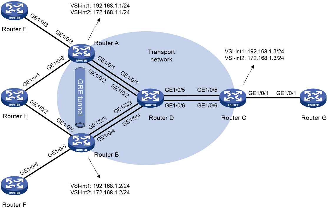
Table 5 Interface and IP address assignment
|
Device |
Interface |
IP address |
Device |
Interface |
IP address |
|
Router A |
GE1/0/1 |
1.1.1.1/24 |
Router D |
GE1/0/1 |
1.1.1.2/24 |
|
GE1/0/2 |
2.1.1.1/24 |
GE1/0/2 |
2.1.1.2/24 |
||
|
GE1/0/3 |
30.1.1.1/24 |
GE1/0/3 |
3.1.1.2/24 |
||
|
GE1/0/6 |
60.1.1.1/24 |
GE1/0/4 |
4.1.1.2/24 |
||
|
Router B |
GE1/0/3 |
3.1.1.1/24 |
GE1/0/5 |
5.1.1.2/24 |
|
|
GE1/0/4 |
4.1.1.1/24 |
GE1/0/6 |
6.1.1.2/24 |
||
|
GE1/0/5 |
50.1.1.1/24 |
Router E |
GE1/0/3 |
30.1.1.2/24 |
|
|
GE1/0/6 |
80.1.1.1/24 |
Router F |
GE1/0/5 |
50.1.1.2/24 |
|
|
Router C |
GE1/0/5 |
5.1.1.1/24 |
Router G |
GE1/0/1 |
10.1.1.2/24 |
|
GE1/0/6 |
6.1.1.1/24 |
Router H |
GE1/0/1 |
60.1.1.2/24 |
|
|
GE1/0/1 |
10.1.1.1/24 |
GE1/0/2 |
80.1.1.2/24 |
Prerequisites
Configure IP addresses and subnet masks for the interfaces as shown in Figure 13.
Procedure
1. Configure OSPF on transport network devices:
# Configure Router A.
<RouterA> system-view
[RouterA] ospf 1
[RouterA-ospf-1] area 0
[RouterA-ospf-1-area-0.0.0.0] network 1.1.1.0 0.0.0.255
[RouterA-ospf-1-area-0.0.0.0] quit
[RouterA-ospf-1] quit
[RouterA] ospf 2
[RouterA-ospf-2] area 0
[RouterA-ospf-2-area-0.0.0.0] network 2.1.1.0 0.0.0.255
[RouterA-ospf-2-area-0.0.0.0] quit
[RouterA-ospf-2] quit
# Configure Router B.
<RouterB> system-view
[RouterB] ospf 1
[RouterB-ospf-1] area 0
[RouterB-ospf-1-area-0.0.0.0] network 3.1.1.0 0.0.0.255
[RouterB-ospf-1-area-0.0.0.0] quit
[RouterB-ospf-1] quit
[RouterB] ospf 2
[RouterB-ospf-2] area 0
[RouterB-ospf-2-area-0.0.0.0] network 4.1.1.0 0.0.0.255
[RouterB-ospf-2-area-0.0.0.0] quit
[RouterB-ospf-2] quit
# Configure Router C.
<RouterC> system-view
[RouterC] ospf 1
[RouterC-ospf-1] area 0
[RouterC-ospf-1-area-0.0.0.0] network 5.1.1.0 0.0.0.255
[RouterC-ospf-1-area-0.0.0.0] quit
[RouterC-ospf-1] quit
[RouterC] ospf 2
[RouterC-ospf-2] area 0
[RouterC-ospf-2-area-0.0.0.0] network 6.1.1.0 0.0.0.255
[RouterC-ospf-2-area-0.0.0.0] quit
[RouterC-ospf-2] quit
# Configure Router D.
<RouterD> system-view
[RouterD] ospf 1
[RouterD-ospf-1] area 0
[RouterD-ospf-1-area-0.0.0.0] network 1.1.1.0 0.0.0.255
[RouterD-ospf-1-area-0.0.0.0] network 3.1.1.0 0.0.0.255
[RouterD-ospf-1-area-0.0.0.0] network 5.1.1.0 0.0.0.255
[RouterD-ospf-1-area-0.0.0.0] quit
[RouterD-ospf-1] quit
[RouterD] ospf 2
[RouterD-ospf-2] area 0
[RouterD-ospf-2-area-0.0.0.0] network 2.1.1.0 0.0.0.255
[RouterD-ospf-2-area-0.0.0.0] network 4.1.1.0 0.0.0.255
[RouterD-ospf-2-area-0.0.0.0] network 6.1.1.0 0.0.0.255
[RouterD-ospf-2-area-0.0.0.0] quit
[RouterD-ospf-2] quit
2. Configure VXLAN settings on transport network devices:
¡ Configure Router A:
# Enable L2VPN.
[RouterA] l2vpn enable
# Create VSI vpna and VXLAN 90.
[RouterA] vsi vpna
[RouterA-vsi-vpna] vxlan 90
[RouterA-vsi-vpna-vxlan-90] quit
[RouterA-vsi-vpna] quit
# Create VSI vpnb and VXLAN 70.
[RouterA] vsi vpnb
[RouterA-vsi-vpnb] vxlan 70
[RouterA-vsi-vpnb-vxlan-70] quit
[RouterA-vsi-vpnb] quit
# Create a VXLAN tunnel to Router C. The tunnel interface name is Tunnel 1. The tunnel source IP address is the IP address of GigabitEthernet 1/0/1 and the tunnel destination address is the IP address of GigabitEthernet 1/0/5 on Router C.
[RouterA] interface tunnel 1 mode vxlan
[RouterA-Tunnel1] source 1.1.1.1
[RouterA-Tunnel1] destination 5.1.1.1
[RouterA-Tunnel1] quit
# Create a VXLAN tunnel to Router C. The tunnel interface name is Tunnel 2. The tunnel source IP address is the IP address of GigabitEthernet 1/0/2 and the tunnel destination address is the IP address of GigabitEthernet 1/0/6 on Router C.
[RouterA] interface tunnel 2 mode vxlan
[RouterA-Tunnel2] source 2.1.1.1
[RouterA-Tunnel2] destination 6.1.1.1
[RouterA-Tunnel2] quit
# Assign Tunnel 1 to VXLAN 90.
[RouterA] vsi vpna
[RouterA-vsi-vpna] vxlan 90
[RouterA-vsi-vpna-vxlan-90] tunnel 1
[RouterA-vsi-vpna-vxlan-90] quit
[RouterA-vsi-vpna] quit
# Assign Tunnel 2 to VXLAN 70.
[RouterA] vsi vpnb
[RouterA-vsi-vpnb] vxlan 70
[RouterA-vsi-vpnb-vxlan-70] tunnel 2
[RouterA-vsi-vpnb-vxlan-70] quit
[RouterA-vsi-vpnb] quit
# Create VSI-interface 1, assign it an IP address, specify the VSI interface as a distributed gateway, and enable local proxy ARP on the interface.
[RouterA] interface vsi-interface 1
[RouterA-Vsi-interface1] ip address 192.168.1.1 255.255.255.0
[RouterA-Vsi-interface1] distributed-gateway local
[RouterA-Vsi-interface1] local-proxy-arp enable
[RouterA-Vsi-interface1] quit
# Create VSI-interface 2, assign it an IP address, specify the VSI interface as a distributed gateway, and enable local proxy ARP on the interface.
[RouterA] interface vsi-interface 2
[RouterA-Vsi-interface2] ip address 172.168.1.1 255.255.255.0
[RouterA-Vsi-interface2] distributed-gateway local
[RouterA-Vsi-interface2] local-proxy-arp enable
[RouterA-Vsi-interface2] quit
# Specify VSI-interface 1 as the gateway interface for VSI vpna. Assign subnet 192.168.1.0/24 to the VSI.
[RouterA] vsi vpna
[RouterA-vsi-vpna] gateway vsi-interface 1
[RouterA-vsi-vpna] gateway subnet 192.168.1.0 0.0.0.255
[RouterA-vsi-vpna] quit
# Specify VSI-interface 2 as the gateway interface for VSI vpnb. Assign subnet 172.168.1.0/24 to the VSI.
[RouterA] vsi vpnb
[RouterA-vsi-vpnb] gateway vsi-interface 2
[RouterA-vsi-vpnb] gateway subnet 172.168.1.0 0.0.0.255
[RouterA-vsi-vpnb] quit
¡ Configure Router B:
# Enable L2VPN.
[RouterB] l2vpn enable
# Create VSI vpna and VXLAN 90.
[RouterB] vsi vpna
[RouterB-vsi-vpna] vxlan 90
[RouterB-vsi-vpna-vxlan-90] quit
[RouterB-vsi-vpna] quit
# Create VSI vpnb and VXLAN 70.
[RouterB] vsi vpnb
[RouterB-vsi-vpnb] vxlan 70
[RouterB-vsi-vpnb-vxlan-70] quit
[RouterB-vsi-vpnb] quit
# Create a VXLAN tunnel to Router C. The tunnel interface name is Tunnel 3. The tunnel source IP address is the IP address of GigabitEthernet 1/0/3 and the tunnel destination address is the IP address of GigabitEthernet 1/0/5 on Router C.
[RouterB] interface tunnel 3 mode vxlan
[RouterB-Tunnel3] source 3.1.1.1
[RouterB-Tunnel3] destination 5.1.1.1
[RouterB-Tunnel3] quit
# Create a VXLAN tunnel to Router C. The tunnel interface name is Tunnel 4. The tunnel source IP address is the IP address of GigabitEthernet 1/0/4 and the tunnel destination address is the IP address of GigabitEthernet 1/0/6 on Router C.
[RouterB] interface tunnel 4 mode vxlan
[RouterB-Tunnel4] source 4.1.1.1
[RouterB-Tunnel4] destination 6.1.1.1
[RouterB-Tunnel4] quit
# Assign Tunnel 3 to VXLAN 90.
[RouterB] vsi vpna
[RouterB-vsi-vpna] vxlan 90
[RouterB-vsi-vpna-vxlan-90] tunnel 3
[RouterB-vsi-vpna-vxlan-90] quit
[RouterB-vsi-vpna] quit
# Assign Tunnel 4 to VXLAN 70.
[RouterB] vsi vpnb
[RouterB-vsi-vpnb] vxlan 70
[RouterB-vsi-vpnb-vxlan-70] tunnel 4
[RouterB-vsi-vpnb-vxlan-70] quit
[RouterB-vsi-vpnb] quit
# Create VSI-interface 1, assign it an IP address, specify the VSI interface as a distributed gateway, and enable local proxy ARP on the interface.
[RouterB] interface vsi-interface 1
[RouterB-Vsi-interface1] ip address 192.168.1.2 255.255.255.0
[RouterB-Vsi-interface1] distributed-gateway local
[RouterB-Vsi-interface1] local-proxy-arp enable
[RouterB-Vsi-interface1] quit
# Create VSI-interface 2, assign it an IP address, specify the VSI interface as a distributed gateway, and enable local proxy ARP on the interface.
[RouterB] interface vsi-interface 2
[RouterB-Vsi-interface2] ip address 172.168.1.2 255.255.255.0
[RouterB-Vsi-interface2] distributed-gateway local
[RouterB-Vsi-interface2] local-proxy-arp enable
[RouterB-Vsi-interface2] quit
# Specify VSI-interface 1 as the gateway interface for VSI vpna. Assign subnet 192.168.1.0/24 to the VSI.
[RouterB] vsi vpna
[RouterB-vsi-vpna] gateway vsi-interface 1
[RouterB-vsi-vpna] gateway subnet 192.168.1.0 0.0.0.255
[RouterB-vsi-vpna] quit
# Specify VSI-interface 2 as the gateway interface for VSI vpnb. Assign subnet 172.168.1.0/24 to the VSI.
[RouterB] vsi vpnb
[RouterB-vsi-vpnb] gateway vsi-interface 2
[RouterB-vsi-vpnb] gateway subnet 172.168.1.0 0.0.0.255
[RouterB-vsi-vpnb] quit
¡ Configure Router C:
# Enable L2VPN.
[RouterC] l2vpn enable
# Create VSI vpna and VXLAN 90.
[RouterC] vsi vpna
[RouterC-vsi-vpna] vxlan 90
[RouterC-vsi-vpna-vxlan-90] quit
[RouterC-vsi-vpna] quit
# Create VSI vpnb and VXLAN 70.
[RouterC] vsi vpnb
[RouterC-vsi-vpnb] vxlan 70
[RouterC-vsi-vpnb-vxlan-70] quit
[RouterC-vsi-vpnb] quit
# Create a VXLAN tunnel to Router A. The tunnel interface name is Tunnel 1. The tunnel source IP address is the IP address of GigabitEthernet 1/0/5 and the tunnel destination address is the IP address of GigabitEthernet 1/0/1 on Router A.
[RouterC] interface tunnel 1 mode vxlan
[RouterC-Tunnel1] source 5.1.1.1
[RouterC-Tunnel1] destination 1.1.1.1
[RouterC-Tunnel1] quit
# Create a VXLAN tunnel to Router A. The tunnel interface name is Tunnel 2. The tunnel source IP address is the IP address of GigabitEthernet 1/0/6 and the tunnel destination address is the IP address of GigabitEthernet 1/0/2 on Router A.
[RouterC] interface tunnel 2 mode vxlan
[RouterC-Tunnel2] source 6.1.1.1
[RouterC-Tunnel2] destination 2.1.1.1
[RouterC-Tunnel2] quit
# Create a VXLAN tunnel to Router B. The tunnel interface name is Tunnel 3. The tunnel source IP address is the IP address of GigabitEthernet 1/0/5 and the tunnel destination address is the IP address of GigabitEthernet 1/0/3 on Router B.
[RouterC] interface tunnel 3 mode vxlan
[RouterC-Tunnel3] source 5.1.1.1
[RouterC-Tunnel3] destination 3.1.1.1
[RouterC-Tunnel3] quit
# Create a VXLAN tunnel to Router B. The tunnel interface name is Tunnel 4. The tunnel source IP address is the IP address of GigabitEthernet 1/0/6 and the tunnel destination address is the IP address of GigabitEthernet 1/0/4 on Router B.
[RouterC] interface tunnel 4 mode vxlan
[RouterC-Tunnel4] source 6.1.1.1
[RouterC-Tunnel4] destination 4.1.1.1
[RouterC-Tunnel4] quit
# Assign Tunnel 1 and Tunnel 3 to VXLAN 90.
[RouterC] vsi vpna
[RouterC-vsi-vpna] vxlan 90
[RouterC-vsi-vpna-vxlan-90] tunnel 1
[RouterC-vsi-vpna-vxlan-90] tunnel 3
[RouterC-vsi-vpna-vxlan-90] quit
[RouterC-vsi-vpna] quit
# Assign Tunnel 2 and Tunnel 4 to VXLAN 70.
[RouterC] vsi vpnb
[RouterC-vsi-vpnb] vxlan 70
[RouterC-vsi-vpnb-vxlan-70] tunnel 2
[RouterC-vsi-vpnb-vxlan-70] tunnel 4
[RouterC-vsi-vpnb-vxlan-70] quit
[RouterC-vsi-vpnb] quit
# Create VSI-interface 1, assign it an IP address, specify the VSI interface as a distributed gateway, and enable local proxy ARP on the interface.
[RouterC] interface vsi-interface 1
[RouterC-Vsi-interface1] ip address 192.168.1.3 255.255.255.0
[RouterC-Vsi-interface1] distributed-gateway local
[RouterC-Vsi-interface1] local-proxy-arp enable
[RouterC-Vsi-interface1] quit
# Create VSI-interface 2, assign it an IP address, specify the VSI interface as a distributed gateway, and enable local proxy ARP on the interface.
[RouterC] interface vsi-interface 2
[RouterC-Vsi-interface2] ip address 172.168.1.3 255.255.255.0
[RouterC-Vsi-interface2] distributed-gateway local
[RouterC-Vsi-interface2] local-proxy-arp enable
[RouterC-Vsi-interface2] quit
# Specify VSI-interface 1 as the gateway interface for VSI vpna. Assign subnet 192.168.1.0/24 to the VSI.
[RouterC] vsi vpna
[RouterC-vsi-vpna] gateway vsi-interface 1
[RouterC-vsi-vpna] gateway subnet 192.168.1.0 0.0.0.255
[RouterC-vsi-vpna] quit
# Specify VSI-interface 2 as the gateway interface for VSI vpnb. Assign subnet 172.168.1.0/24 to the VSI.
[RouterC] vsi vpnb
[RouterC-vsi-vpnb] gateway vsi-interface 2
[RouterC-vsi-vpnb] gateway subnet 172.168.1.0 0.0.0.255
[RouterC-vsi-vpnb] quit
3. Configure BGP:
# Configure Router A.
[RouterA] bgp 100
[RouterA-bgp-default] peer 30.1.1.2 as-number 100
[RouterA-bgp-default] peer 172.168.1.3 as-number 200
[RouterA-bgp-default] peer 192.168.1.3 as-number 200
[RouterA-bgp-default] address-family ipv4 unicast
[RouterA-bgp-default-ipv4] balance 4
[RouterA-bgp-default-ipv4] peer 30.1.1.2 enable
[RouterA-bgp-default-ipv4] peer 30.1.1.2 next-hop-local
[RouterA-bgp-default-ipv4] peer 172.168.1.3 enable
[RouterA-bgp-default-ipv4] peer 192.168.1.3 enable
[RouterA-bgp-default-ipv4] quit
[RouterA-bgp-default] quit
# Configure Router B.
[RouterB] bgp 100
[RouterB-bgp-default] peer 50.1.1.2 as-number 100
[RouterB-bgp-default] peer 172.168.1.3 as-number 200
[RouterB-bgp-default] peer 192.168.1.3 as-number 200
[RouterB-bgp-default] address-family ipv4 unicast
[RouterB-bgp-default-ipv4] balance 4
[RouterB-bgp-default-ipv4] peer 50.1.1.2 enable
[RouterB-bgp-default-ipv4] peer 50.1.1.2 next-hop-local
[RouterB-bgp-default-ipv4] peer 172.168.1.3 enable
[RouterB-bgp-default-ipv4] peer 192.168.1.3 enable
[RouterB-bgp-default-ipv4] quit
[RouterB-bgp-default] quit
# Configure Router C.
[RouterC] bgp 200
[RouterC-bgp-default] peer 10.1.1.2 as-number 200
[RouterC-bgp-default] peer 172.168.1.1 as-number 100
[RouterC-bgp-default] peer 192.168.1.1 as-number 100
[RouterC-bgp-default] peer 172.168.1.2 as-number 100
[RouterC-bgp-default] peer 192.168.1.2 as-number 100
[RouterC-bgp-default] address-family ipv4 unicast
[RouterC-bgp-default-ipv4] balance 4
[RouterC-bgp-default-ipv4] peer 10.1.1.2 enable
[RouterC-bgp-default-ipv4] peer 10.1.1.2 next-hop-local
[RouterC-bgp-default-ipv4] peer 172.168.1.1 enable
[RouterC-bgp-default-ipv4] peer 192.168.1.1 enable
[RouterC-bgp-default-ipv4] peer 172.168.1.2 enable
[RouterC-bgp-default-ipv4] peer 192.168.1.2 enable
[RouterC-bgp-default-ipv4] quit
[RouterC-bgp-default] quit
# Configure Router E.
<RouterE> system-view
[RouterE] bgp 100
[RouterE-bgp-default] peer 30.1.1.1 as-number 100
[RouterE-bgp-default] address-family ipv4 unicast
[RouterE-bgp-default-ipv4] import-route direct
[RouterE-bgp-default-ipv4] peer 30.1.1.1 enable
[RouterE-bgp-default-ipv4] quit
[RouterE-bgp-default] quit
# Configure Router F.
<RouterF> system-view
[RouterF] bgp 100
[RouterF-bgp-default] peer 50.1.1.1 as-number 100
[RouterF-bgp-default] address-family ipv4 unicast
[RouterF-bgp-default-ipv4] import-route direct
[RouterF-bgp-default-ipv4] peer 50.1.1.1 enable
[RouterF-bgp-default-ipv4] quit
[RouterF-bgp-default] quit
# Configure Router G.
<RouterG> system-view
[RouterG] bgp 200
[RouterG-bgp-default] peer 10.1.1.1 as-number 200
[RouterG-bgp-default] address-family ipv4 unicast
[RouterG-bgp-default-ipv4] import-route direct
[RouterG-bgp-default-ipv4] peer 10.1.1.1 enable
[RouterG-bgp-default-ipv4] quit
[RouterG-bgp-default] quit
4. Configure basic RIR features:
¡ Configure Router A:
# Enable the RIR server globally and specify a synchronization port for receiving probe information from RIR clients.
[RouterA] rir
[RouterA-rir] server enable
[RouterA-rir] probe sync-port 65535
# Set the link selection delay to 30 seconds and set the link selection suppression period to 60 seconds.
[RouterA-rir] link-select delay 30
[RouterA-rir] link-select suppress-period 60
[RouterA-rir] quit
# Enable the NQA server and configure UDP listening services on the NQA server.
[RouterA] nqa server enable
[RouterA] nqa server udp-echo 1.1.1.1 65501 high-performance-mode
[RouterA] nqa server udp-echo 1.1.1.1 65502 high-performance-mode
[RouterA] nqa server udp-echo 2.1.1.1 65501 high-performance-mode
[RouterA] nqa server udp-echo 2.1.1.1 65502 high-performance-mode
# Set the link type to MPLS and link index to 1 on VSI-interface 1.
[RouterA] interface vsi-interface 1
[RouterA-Vsi-interface1] rir link-type mpls index 1
[RouterA-Vsi-interface1] quit
# Set the link type to Internet and link index to 2 on VSI-interface 2.
[RouterA] interface vsi-interface 2
[RouterA-Vsi-interface2] rir link-type internet index 2
[RouterA-Vsi-interface2] quit
# Set the bandwidth of VXLAN tunnel interface Tunnel 1 to 30000 kbps.
[RouterA] interface tunnel 1 mode vxlan
[RouterA-Tunnel1] bandwidth 30000
[RouterA-Tunnel1] quit
# Set the bandwidth of VXLAN tunnel interface Tunnel 2 to 30000 kbps.
[RouterA] interface tunnel 2 mode vxlan
[RouterA-Tunnel2] bandwidth 30000
[RouterA-Tunnel2] quit
# Create flow template 1 and flow template 2. Assign different link preference values to the two links in each flow template, and specify the per-session expected bandwidth in each flow template. No quality policy is configured for the flow templates.
[RouterA] rir
[RouterA-rir] flow 1
[RouterA-rir-flow-1] path link-type mpls index 1 preference 10
[RouterA-rir-flow-1] path link-type internet index 2 preference 30
[RouterA-rir-flow-1] expect-bandwidth 300
[RouterA-rir-flow-1] quit
[RouterA-rir] quit
[RouterA-rir] flow 2
[RouterA-rir-flow-2] path link-type mpls index 1 preference 20
[RouterA-rir-flow-2] path link-type internet index 2 preference 40
[RouterA-rir-flow-2] expect-bandwidth 300
[RouterA-rir-flow-2] quit
[RouterA-rir] quit
# Configure a QoS policy to match packets with a DSCP value of 1 to flow template 1 and match packets with a DSCP value of 2 to flow template 2. Apply the QoS policy to the inbound direction of GigabitEthernet 1/0/3.
[RouterA] traffic classifier class1
[RouterA-classifier-class1] if-match dscp 1
[RouterA-classifier-class1] quit
[RouterA] traffic classifier class2
[RouterA-classifier-class2] if-match dscp 2
[RouterA-classifier-class2] quit
[RouterA] traffic behavior behav1
[RouterA-behavior-behav1] remark flow-id 1
[RouterA-behavior-behav1] quit
[RouterA] traffic behavior behav2
[RouterA-behavior-behav2] remark flow-id 2
[RouterA-behavior-behav2] quit
[RouterA] qos policy policy1
[RouterA-qospolicy-policy1] classifier class1 behavior behav1
[RouterA-qospolicy-policy1] classifier class2 behavior behav2
[RouterA-qospolicy-policy1] quit
[RouterA] interface gigabitethernet 1/0/3
[RouterA-GigabitEthernet1/0/3] qos apply policy policy1 inbound
[RouterA-GigabitEthernet1/0/3] quit
¡ Configure Router B:
# Enable the RIR server globally and specify a synchronization port for receiving probe information from RIR clients.
[RouterB] rir
[RouterB-rir] server enable
[RouterB-rir] probe sync-port 65535
# Set the link selection delay to 30 seconds and set the link selection suppression period to 60 seconds.
[RouterB-rir] link-select delay 30
[RouterB-rir] link-select suppress-period 60
[RouterB-rir] quit
# Enable the NQA server and configure UDP listening services on the NQA server.
[RouterB] nqa server enable
[RouterB] nqa server udp-echo 3.1.1.1 65501 high-performance-mode
[RouterB] nqa server udp-echo 3.1.1.1 65502 high-performance-mode
[RouterB] nqa server udp-echo 4.1.1.1 65501 high-performance-mode
[RouterB] nqa server udp-echo 4.1.1.1 65502 high-performance-mode
# Set the link type to MPLS and link index to 1 on VSI-interface 1.
[RouterB] interface vsi-interface 1
[RouterB-Vsi-interface1] rir link-type mpls index 1
[RouterB-Vsi-interface1] quit
# Set the link type to Internet and link index to 2 on VSI-interface 2.
[RouterB] interface vsi-interface 2
[RouterB-Vsi-interface2] rir link-type internet index 2
[RouterB-Vsi-interface2] quit
# Set the bandwidth of VXLAN tunnel interface Tunnel 3 to 30000 kbps.
[RouterB] interface tunnel 3 mode vxlan
[RouterB-Tunnel3] bandwidth 30000
[RouterB-Tunnel3] quit
# Set the bandwidth of VXLAN tunnel interface Tunnel 4 to 30000 kbps.
[RouterB] interface tunnel 4 mode vxlan
[RouterB-Tunnel4] bandwidth 30000
[RouterB-Tunnel4] quit
# Create flow template 1 and flow template 2. Assign different link preference values to the two links in each flow template, and specify the per-session expected bandwidth in each flow template. No quality policy is configured for the flow templates.
[RouterB-rir] flow 1
[RouterB-rir-flow-1] path link-type mpls index 1 preference 10
[RouterB-rir-flow-1] path link-type internet index 2 preference 30
[RouterB-rir-flow-1] expect-bandwidth 300
[RouterB-rir-flow-1] quit
[RouterB-rir] quit
[RouterB-rir] flow 2
[RouterB-rir-flow-2] path link-type mpls index 1 preference 20
[RouterB-rir-flow-2] path link-type internet index 2 preference 40
[RouterB-rir-flow-2] expect-bandwidth 300
[RouterB-rir-flow-2] quit
[RouterB-rir] quit
# Configure a QoS policy to match packets with a DSCP value of 1 to flow template 1 and match packets with a DSCP value of 2 to flow template 2. Apply the QoS policy to the inbound direction of GigabitEthernet 1/0/5.
[RouterB] traffic classifier class1
[RouterB-classifier-class1] if-match dscp 1
[RouterB-classifier-class1] quit
[RouterB] traffic classifier class2
[RouterB-classifier-class2] if-match dscp 2
[RouterB-classifier-class2] quit
[RouterB] traffic behavior behav1
[RouterB-behavior-behav1] remark flow-id 1
[RouterB-behavior-behav1] quit
[RouterB] traffic behavior behav2
[RouterB-behavior-behav2] remark flow-id 2
[RouterB-behavior-behav2] quit
[RouterB] qos policy policy1
[RouterB-qospolicy-policy1] classifier class1 behavior behav1
[RouterB-qospolicy-policy1] classifier class2 behavior behav2
[RouterB-qospolicy-policy1] quit
[RouterB] interface gigabitethernet 1/0/5
[RouterB-GigabitEthernet1/0/5] qos apply policy policy1 inbound
[RouterB-GigabitEthernet1/0/5] quit
¡ Configure Router C:
# Enable the RIR client globally and specify a port for synchronizing probe information to RIR servers.
[RouterC] rir
[RouterC-rir] client enable
[RouterC-rir] probe sync-port 65535
# Set the link selection delay to 30 seconds and set the link selection suppression period to 60 seconds.
[RouterC-rir] link-select delay 30
[RouterC-rir] link-select suppress-period 60
[RouterC-rir] quit
# Enable the NQA client.
[RouterC] nqa agent enable
# Configure NQA link connectivity probe parameters.
[RouterC] rir
[RouterC-rir] probe connect interval 300 timeout 65535
# Create NQA link quality operation 1 and NQA link quality operation 2, and configure different link quality probe parameters for the operations.
[RouterC-rir] nqa 1
[RouterC-rir-nqa-1] probe packet-dscp 10
[RouterC-rir-nqa-1] probe interval 60
[RouterC-rir-nqa-1] probe packet-interval 15
[RouterC-rir-nqa-1] probe packet-number 60
[RouterC-rir-nqa-1] probe packet-timeout 500
[RouterC-rir-nqa-1] probe port 65501
[RouterC-rir-nqa-1] quit
[RouterC-rir] nqa 2
[RouterC-rir-nqa-2] probe packet-dscp 20
[RouterC-rir-nqa-2] probe interval 120
[RouterC-rir-nqa-2] probe packet-interval 30
[RouterC-rir-nqa-2] probe packet-number 120
[RouterC-rir-nqa-2] probe packet-timeout 1000
[RouterC-rir-nqa-2] probe port 65502
[RouterC-rir-nqa-2] quit
# Create SLA 1 and SLA 2, and configure different link quality thresholds for the SLAs.
[RouterC-rir] sla 1
[RouterC-rir-sla-1] jitter threshold 20
[RouterC-rir-sla-1] delay threshold 60
[RouterC-rir-sla-1] packet-loss threshold 150
[RouterC-rir-sla-1] quit
[RouterC-rir] sla 2
[RouterC-rir-sla-2] jitter threshold 40
[RouterC-rir-sla-2] delay threshold 120
[RouterC-rir-sla-2] packet-loss threshold 300
[RouterC-rir-sla-2] quit
[RouterC-rir] quit
# Set the link type to MPLS and link index to 1 on VSI-interface 1.
[RouterC] interface vsi-interface 1
[RouterC-Vsi-interface1] rir link-type mpls index 1
[RouterC-Vsi-interface1] quit
# Set the link type to Internet and link index to 2 on VSI-interface 2.
[RouterC] interface vsi-interface 2
[RouterC-Vsi-interface2] rir link-type internet index 2
[RouterC-Vsi-interface2] quit
# Set the bandwidth of VXLAN tunnel interface Tunnel 1 to 30000 kbps.
[RouterC] interface tunnel 1 mode vxlan
[RouterC-Tunnel1] bandwidth 30000
[RouterC-Tunnel1] quit
# Set the bandwidth of VXLAN tunnel interface Tunnel 2 to 30000 kbps.
[RouterC] interface tunnel 2 mode vxlan
[RouterC-Tunnel2] bandwidth 30000
[RouterC-Tunnel2] quit
# Set the bandwidth of VXLAN tunnel interface Tunnel 3 to 30000 kbps.
[RouterC] interface tunnel 3 mode vxlan
[RouterC-Tunnel3] bandwidth 30000
[RouterC-Tunnel3] quit
# Set the bandwidth of VXLAN tunnel interface Tunnel 4 to 30000 kbps.
[RouterC] interface tunnel 4 mode vxlan
[RouterC-Tunnel4] bandwidth 30000
[RouterC-Tunnel4] quit
# Create flow template 1 and flow template 2, and assign the same link preference value to the links in each flow template. Configure different quality policies for each flow template and specify the per-session expected bandwidth in each flow template.
[RouterC] rir
[RouterC-rir] flow 1
[RouterC-rir-flow-1] path link-type mpls index 1 preference 10
[RouterC-rir-flow-1] path link-type internet index 2 preference 10
[RouterC-rir-flow-1] expect-bandwidth 300
[RouterC-rir-flow-1] quality-policy sla 1 nqa 1
[RouterC-rir-flow-1] quit
[RouterC-rir] flow 2
[RouterC-rir-flow-2] path link-type mpls index 1 preference 20
[RouterC-rir-flow-2] path link-type internet index 2 preference 20
[RouterC-rir-flow-2] expect-bandwidth 300
[RouterC-rir-flow-2] quality-policy sla 2 nqa 2
[RouterC-rir-flow-2] quit
[RouterC-rir] quit
# Configure a QoS policy to match packets with a DSCP value of 1 to flow template 1 and match packets with a DSCP value of 2 to flow template 2. Apply the QoS policy to the inbound direction of GigabitEthernet 1/0/1.
[RouterC] traffic classifier class1
[RouterC-classifier-class1] if-match dscp 1
[RouterC-classifier-class1] quit
[RouterC] traffic classifier class2
[RouterC-classifier-class2] if-match dscp 2
[RouterC-classifier-class2] quit
[RouterC] traffic behavior behav1
[RouterC-behavior-behav1] remark flow-id 1
[RouterC-behavior-behav1] quit
[RouterC] traffic behavior behav2
[RouterC-behavior-behav2] remark flow-id 2
[RouterC-behavior-behav2] quit
[RouterC] qos policy policy1
[RouterC-qospolicy-policy1] classifier class1 behavior behav1
[RouterC-qospolicy-policy1] classifier class2 behavior behav2
[RouterC-qospolicy-policy1] quit
[RouterC] interface gigabitethernet 1/0/1
[RouterC-GigabitEthernet1/0/1] qos apply policy policy1 inbound
[RouterC-GigabitEthernet1/0/1] quit
5. Configure RIR collaboration:
¡ Configure Router A:
# Configure a GRE tunnel.
[RouterA] interface tunnel 10 mode gre
[RouterA-Tunnel10] ip address 150.1.1.1 255.255.255.0
[RouterA-Tunnel10] source 60.1.1.1
[RouterA-Tunnel10] destination 80.1.1.1
# Apply QoS policy policy1 to the inbound direction of tunnel interface Tunnel 10.
[RouterA] interface tunnel 10
[RouterA-Tunnel10] qos apply policy policy1 inbound
[RouterA-Tunnel10] quit
# Assign VXLAN tunnel 1 and VXLAN tunnel 2 to RIR collaboration link group 3.
[RouterA] interface tunnel 1
[RouterA-Tunnel1] rir collaboration-link-group 3
[RouterA-Tunnel1] quit
[RouterA] interface tunnel 2
[RouterA-Tunnel2] rir collaboration-link-group 3
[RouterA-Tunnel2] quit
# Configure Router A to establish RIR collaboration relationship with Router B. They use TCP port number 3000 for link data synchronization.
[RouterA] rir
[RouterA-rir] collaboration peer 150.1.1.2 local 150.1.1.1 sync-port 3000
[RouterA] quit
# Configure 150.1.1.2 as the redirect IP address for packets redirected to Router B on the public network.
[RouterA] rir
[RouterA-rir] collaboration peer 150.1.1.2 redirect 150.1.1.2
[RouterA] quit
¡ Configure Router B:
# Configure a GRE tunnel.
[RouterB] interface tunnel 10 mode gre
[RouterB-Tunnel10] ip address 150.1.1.2 255.255.255.0
[RouterB-Tunnel10] source 80.1.1.1
[RouterB-Tunnel10] destination 60.1.1.1
# Apply QoS policy policy1 to the inbound direction of tunnel interface Tunnel 10.
[RouterB] interface tunnel 10
[RouterB-Tunnel10] qos apply policy policy1 inbound
[RouterB-Tunnel10] quit
# Assign VXLAN tunnel 3 and VXLAN tunnel 4 to RIR collaboration link group 3.
[RouterB] interface tunnel 3
[RouterB-Tunnel3] rir collaboration-link-group 3
[RouterB-Tunnel3] quit
[RouterB] interface tunnel 4
[RouterB-Tunnel4] rir collaboration-link-group 3
[RouterB-Tunnel4] quit
# Configure Router B to establish RIR collaboration relationship with Router A. They use TCP port number 3000 for link data synchronization.
[RouterB] rir
[RouterB-rir] collaboration peer 150.1.1.1 local 150.1.1.2 sync-port 3000
[RouterB] quit
# Configure 150.1.1.1 as the redirect IP address for packets redirected to Router A on the public network.
[RouterB] rir
[RouterB-rir] collaboration peer 150.1.1.1 redirect 150.1.1.1
[RouterB] quit
6. Configure flow ID-based traffic rate statistics for tunnels:
# On Router A, enable flow ID-based traffic rate statistics for tunnels and set the statistics collection interval to 5 seconds.
[RouterA] tunnel flow-statistics enable
[RouterA] tunnel flow-statistics interval 5
# On Router B, enable flow ID-based traffic rate statistics for tunnels and set the statistics collection interval to 5 seconds.
[RouterB] tunnel flow-statistics enable
[RouterB] tunnel flow-statistics interval 5
# On Router C, enable flow ID-based traffic rate statistics for tunnels and set the statistics collection interval to 5 seconds.
[RouterC] tunnel flow-statistics enable
[RouterC] tunnel flow-statistics interval 5
Verifying the configuration
1. View ECMP routes:
# On Router A, display information about routes destined for Router G.
[RouterA] display ip routing-table 10.1.1.2
Summary count : 2
Destination/Mask Proto Pre Cost NextHop Interface
10.1.1.0/24 BGP 255 0 172.168.1.3 Vsi2
BGP 255 0 192.168.1.3 Vsi1
The output shows that two ECMP routes are available and the output interfaces of the routes are the VSI interfaces.
# On Router B, display information about routes destined for Router G.
[RouterB] display ip routing-table 10.1.1.2
Summary count : 2
Destination/Mask Proto Pre Cost NextHop Interface
10.1.1.0/24 BGP 255 0 172.168.1.3 Vsi2
BGP 255 0 192.168.1.3 Vsi1
The output shows that two ECMP routes are available and the output interfaces of the routes are the VSI interfaces.
# On Router C, display information about routes destined for Router E and Router F.
[RouterC] display ip routing-table 30.1.1.2
Summary count : 2
Destination/Mask Proto Pre Cost NextHop Interface
30.1.1.0/24 BGP 255 0 172.168.1.1 Vsi2
BGP 255 0 192.168.1.1 Vsi1
[RouterC] display ip routing-table 50.1.1.2
Summary count : 2
Destination/Mask Proto Pre Cost NextHop Interface
50.1.1.0/24 BGP 255 0 172.168.1.2 Vsi2
BGP 255 0 192.168.1.2 Vsi1
The output shows that two ECMP routes are available to reach each router and the output interfaces of the routes are the VSI interfaces.
2. View TCP connections:
# On Router A (a hub), display TCP connection information.
[RouterA] display tcp
*: TCP connection with authentication
Local Addr:port Foreign Addr:port State Slot PCB
0.0.0.0:179 30.1.1.2:0 LISTEN 1 0xffffffffffffffa0
0.0.0.0:179 172.168.1.3:0 LISTEN 1 0x00000000000003f2
0.0.0.0:179 192.168.1.3:0 LISTEN 1 0x000000000000049a
0.0.0.0:65535 0.0.0.0:0 LISTEN 1 0x0000000000000382
1.1.1.1:65535 5.1.1.1:22235 ESTABLISHED 1 0x0000000000000520
2.1.1.1:65535 6.1.1.1:62560 ESTABLISHED 1 0x0000000000000498
30.1.1.1:179 30.1.1.2:12480 ESTABLISHED 1 0x00000000000003ec
150.1.1.1:49210 150.1.1.2:3000 ESTABLISHED 1 0x000000000000050c
172.168.1.1:179 172.168.1.3:62558 ESTABLISHED 1 0x0000000000000496
192.168.1.1:179 192.168.1.3:22233 ESTABLISHED 1 0x000000000000051f
The output shows that the router has established two TCP connections with a local port number of 65535 and one TCP connection with a foreign port number of 3000. The spoke in this example can use the TCP connections with a local port number of 65535 to synchronize link quality probe results to the hub. The hub can use the TCP connection with a foreign port number of 3000 to synchronize link data to the peer hub. TCP connections with a local or foreign port number of 179 are generated when starts running.
# On Router B (a hub), display TCP connection information.
[RouterB] display tcp
*: TCP connection with authentication
Local Addr:port Foreign Addr:port State Slot PCB
0.0.0.0:179 50.1.1.2:0 LISTEN 1 0xffffffffffffffa0
0.0.0.0:179 172.168.1.3:0 LISTEN 1 0xffffffffffffffa2
0.0.0.0:179 192.168.1.3:0 LISTEN 1 0xffffffffffffffa1
0.0.0.0:65535 0.0.0.0:0 LISTEN 1 0xffffffffffffffe8
3.1.1.1:65535 5.1.1.1:5908 ESTABLISHED 1 0xffffffffffffffea
4.1.1.1:65535 6.1.1.1:5909 ESTABLISHED 1 0xffffffffffffffeb
50.1.1.1:179 50.1.1.2:30400 ESTABLISHED 1 0x0000000000000019
150.1.1.2:3000 150.1.1.1:0 LISTEN 1 0x000000000000001a
150.1.1.2:3000 150.1.1.1:49210 ESTABLISHED 1 0x000000000000001b
172.168.1.2:23298 172.168.1.3:179 ESTABLISHED 1 0xffffffffffffffa6
192.168.1.2:179 192.168.1.3:29379 ESTABLISHED 1 0xffffffffffffffa7
The output shows that the router has established two TCP connections with a local port number of 65535 and one TCP connection with a local port number of 3000. The spoke in this example can use the TCP connections with a local port number of 65535 to synchronize link quality probe results to the hub. The hub can use the TCP connection with a local port number of 3000 to synchronize link data to the peer hub. TCP connections with a local or foreign port number of 179 are generated when starts running.
# On Router C (a spoke), display TCP connection information.
[RouterC] display tcp
*: TCP connection with authentication
Local Addr:port Foreign Addr:port State Slot PCB
0.0.0.0:179 10.1.1.2:0 LISTEN 1 0xffffffffffffffa6
0.0.0.0:179 172.168.1.1:0 LISTEN 1 0x0000000000000034
0.0.0.0:179 172.168.1.2:0 LISTEN 1 0xffffffffffffffa4
0.0.0.0:179 192.168.1.1:0 LISTEN 1 0x00000000000000d6
0.0.0.0:179 192.168.1.2:0 LISTEN 1 0xffffffffffffffa2
5.1.1.1:5908 3.1.1.1:65535 ESTABLISHED 1 0xffffffffffffffff
5.1.1.1:22235 1.1.1.1:65535 ESTABLISHED 1 0x000000000000014b
6.1.1.1:5909 4.1.1.1:65535 ESTABLISHED 1 0x0000000000000001
6.1.1.1:62560 2.1.1.1:65535 ESTABLISHED 1 0x00000000000000cf
10.1.1.1:179 10.1.1.2:48512 ESTABLISHED 1 0x000000000000002c
172.168.1.3:179 172.168.1.2:23298 ESTABLISHED 1 0xffffffffffffffad
172.168.1.3:62558 172.168.1.1:179 ESTABLISHED 1 0x00000000000000cd
192.168.1.3:22233 192.168.1.1:179 ESTABLISHED 1 0x0000000000000149
192.168.1.3:29379 192.168.1.2:179 ESTABLISHED 1 0xffffffffffffffae
The output shows that four TCP connections with a foreign port number of 65535 have been established. The spoke can use the TCP connections to synchronize link quality probe results to the hubs. TCP connections with a local or foreign port number of 179 are generated when starts running.
3. Display link selection information:
¡ On Router A:
# Use Router E to initiate UDP services only to Router G on the public network. The services have multiple sessions and the DSCP of the service traffic is 1. (Details not shown.)
# On Router A, display flow ID-based traffic rate statistics for tunnels to verify that only Tunnel 1 on the local device has service traffic in flow template 1.
[RouterA] display tunnel flow-statistics
RIR flow 1:
Interface Out pps Out bps
Tunnel1 300 300000
The output shows that RIR preferentially selects Tunnel 1 on the local device for the service traffic with a DSCP value of 1 in flow template 1.
# Use Router E to initiate UDP services only to Router G on the public network. The services have multiple sessions and the DSCP of the service traffic is 2. (Details not shown.)
# On Router A, display flow ID-based traffic rate statistics for tunnels to verify that only Tunnel 1 on the local device has service traffic in flow template 2.
[RouterA] display tunnel flow-statistics
RIR flow 2:
Interface Out pps Out bps
Tunnel1 300 300000
The output shows that RIR preferentially selects Tunnel 1 on the local device for the service traffic with a DSCP value of 2 in flow template 2.
¡ On Router B:
# Use Router F to initiate UDP services only to Router G on the public network. The services have multiple sessions and the DSCP of the service traffic is 1. (Details not shown.)
# On Router B, display flow ID-based traffic rate statistics for tunnels to verify that only Tunnel 1 on the peer device has service traffic in flow template 1.
[RouterB] display tunnel flow-statistics
RIR flow 1:
Interface Out pps Out bps
Tunnel1 300 300000
The output shows that RIR preferentially selects Tunnel 1 on the peer device for the service traffic with a DSCP value of 1 in flow template 1.
# Use Router F to initiate UDP services only to Router G on the public network. The services have multiple sessions and the DSCP of the service traffic is 2. (Details not shown.)
# On Router B, display flow ID-based traffic rate statistics for tunnels to verify that only Tunnel 1 on the peer device has service traffic in flow template 2.
[RouterB] display tunnel flow-statistics
RIR flow 2:
Interface Out pps Out bps
Tunnel1 300 300000
The output shows that RIR preferentially selects Tunnel 1 on the peer device for the service traffic with a DSCP value of 2 in flow template 2.
¡ On Router C:
# Use Router G to initiate UDP services only to Router E. The services have multiple sessions and the DSCP of the service traffic is 1. (Details not shown.)
# On Router C, display flow ID-based traffic rate statistics for tunnels to verify that both Tunnel 1 and Tunnel 2 in flow template 1 have service traffic.
[RouterC] display tunnel flow-statistics
RIR flow 1:
Interface Out pps Out bps
Tunnel1 300 300000
Tunnel2 300 300000
The output shows that RIR selects two links to load share the service traffic with a DSCP value of 1 in flow template 1.
# Use Router G to initiate UDP services only to Router E. The services have multiple sessions and the DSCP of the service traffic is 2. (Details not shown.)
# On Router C, display flow ID-based traffic rate statistics for tunnels to verify that both Tunnel 1 and Tunnel 2 in flow template 2 have service traffic.
[RouterC] display tunnel flow-statistics
RIR flow 2:
Interface Out pps Out bps
Tunnel1 300 300000
Tunnel2 300 300000
The output shows that RIR selects two links to load share the service traffic with a DSCP value of 2 in flow template 2.
# Use Router G to initiate UDP services to Router F. The link selection information on Router C is the same as the link selection information for services initiated from Router G to Router E. (Details not shown.)
4. Display fast forwarding entries:
# Use Router E to initiate UDP services only to Router G on the public network. The services have multiple sessions and the DSCP of the service traffic is 1. (Details not shown.)
# On Router A, display fast forwarding entries to verify that the output interface is VSI-interface 1 for the traffic destined for 10.1.1.2.
[RouterA] display ip fast-forwarding cache 10.1.1.2
Total number of fast-forwarding entries: 2
SIP SPort DIP DPort Pro Input_If Output_If Flg
30.1.1.2 246 10.1.1.2 2048 1 GE1/0/3 Vsi1 1
# Shut down tunnel interface Tunnel 1 on Router A. Then, display fast forwarding entries on the router to verify that the output interface becomes tunnel interface Tunnel 10 for the traffic destined for 10.1.1.2. If Router A cannot select a local link to forward the traffic destined for 10.1.1.2, it will redirect the traffic to Router B. Router B will perform link selection to forward the traffic.
[RouterA] display ip fast-forwarding cache 10.1.1.2
Total number of fast-forwarding entries: 2
SIP SPort DIP DPort Pro Input_If Output_If Flg
30.1.1.2 246 10.1.1.2 2048 1 GE1/0/3 Tun10 1
