- Table of Contents
- Related Documents
-
| Title | Size | Download |
|---|---|---|
| 02-VM configuration | 208.66 KB |
Contents
Restrictions: Hardware compatibility with VMs
VM configuration tasks at a glance
Removing a disk or CD-ROM from a VM
Specifying a boot order number for a disk or CD-ROM
Setting the physical NIC network mode for VMs
Setting the forwarding mode of a physical NIC
Specifying a VLAN for a VF interface
Removing an SR-IOV NIC from a VM
Specifying a VLAN for a vTap NIC
Allocating CPU cores to the VM plane
Binding vCPU cores to physical CPU cores
Setting the minimum amount of physical memory available for the Comware system
Configuring VNC parameters for remote VM login
Display and maintenance commands for VMs
Configuring virtual machines
About virtual machine hosting
A virtual machine (VM) is a complete computer system running in an isolated environment with full hardware system functions simulated by software. A VM can provide the same services as a physical computer. When creating a VM, you need to assign part of the CPU, memory, and hard disk resources on the physical device that hosts the VM to the VM. Each VM can install an operating system like a physical computer for service processing.
The device can act as an ICT converged gateway that integrates IT and CT. It supports VM deployment through x86 virtualization technology to complete interaction of service data for enterprise users.
Architecture
The device can host one or multiple VMs. The maximum number of hosted VMs on the device depends on the device's CPU and memory usage. The device can use Layer 2 broadcast and Layer 3 routing to communicate with a VM, as shown in Figure 1.
|
|
IMPORTANT: The dotted lines in the figure represent links virtualized by software. The virtual links only indicate the connection relationship. The solid lines represent physical links that actually exist inside the device. |
Figure 1 MSR router architecture

As shown in Figure 1, the router architecture contains the following components:
· VMs—Deployed as needed on the router to offer new applications or services. The operating system of a VM is called the guest OS.
· SR-IOV NIC—NIC built with single route input/output virtualization (SR-IOV) technology to support hardware-based virtualization. VMs use the SR-IOV physical function (PF) to access the I/O modules through the physical SR-IOV NIC at high performance as if through physical interfaces.
· VF—The SR-IOV technology virtualizes a physical function (PF) into multiple virtual functions (VFs). Typically, a physical NIC is a PF. VMs use the VFs virtualized from the PF as their virtual NICs. The Comware system supports a maximum of eight VFs numbered from 0 to 7. By default, the VFs do not belong to a VLAN.
· vTap—Software-based virtual NIC that connects a VM to the vSwitch. The device reserves eight MAC addresses for vTap NICs to use.
· VM-Ethernet—Virtual Layer 2 Ethernet interfaces on the virtual software switching system (vSwitch). The Comware system supports eight VM-Ethernet interfaces. By default, the interfaces belong to VLAN 1. The system randomly associates a VM-Ethernet interface with a vTap NIC.
· vSwitch—Virtual software switching system. The vSwitch provides Layer 2 VM-Ethernet interfaces for VM vTap NICs.
· Router—The routing system.
· Switch—Switching system.
· WAN—Layer 3 Ethernet ports.
· LAN—Layer 2 Ethernet ports. By default, the ports belong to VLAN 1.
· LAN (internal)—An internal Layer 2 Ethernet interface connected to the SR-IOV NIC. By default, the link type of the interface is trunk.
Supported vNICs
The VMs can use vTap and SR-IOV NICs for network connectivity.
vTap NIC
A vTap NIC provides software-based forwarding. It is slower than an SR-IOV NIC. However, you do not need to install any driver for the vTap NICs. In addition, the vTap NICs can run on a low version operating system.
Use vTap NICs in scenarios where VMs do not process much service data.
SR-IOV NIC
An SR-IOV NIC provides hardware-based forwarding. It forwards traffic at higher speeds than vTap NICs.
The system supports the following physical NIC network modes based on how a physical SR-IOV NIC is used:
· Passthrough—The physical NIC is allocated to a VM exclusively. The VM uses the PF interface of the physical NIC for communication. By default, the passthrough mode is used.
· SR-IOV share—Multiple VMs share the physical NIC. The VMs use the VF interfaces of the physical NIC for communication.
|
|
NOTE: To use SR-IOV NICs for VM connectivity, you must install an SR-IOV NIC driver in the guest OS of VMs. For this purpose, you must add a vTap NIC first and use the network service provided by the vTap NIC to download the SR-IOV NIC driver. |
Communication mechanisms
Communication scenarios
Table 1 Communication scenarios and used interfaces
|
Scenario |
Ports or interfaces |
|
VM-VM traffic forwarding |
· Between vTap interfaces · Between a vTap interface and a PF or VF interface · Between PF or VF interfaces |
|
VM-WAN traffic forwarding |
· Between a vTap interface and a WAN port · Between a PF or VF interface and a WAN port |
|
VM-LAN traffic forwarding |
· Between a vTap interface and a LAN port · Between a PF or VF interface and a LAN port |
VM-VM traffic forwarding
Figure 2 illustrates the forwarding path for the traffic between the vTap interfaces of two VMs. The vSwitch is used to forward the traffic.
Figure 2 vTap-vTap traffic forwarding
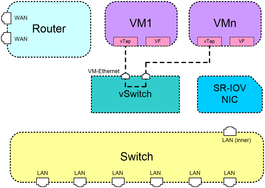
Figure 3 illustrates the forwarding path for the traffic from a vTap interface on one VM to a VF interface on another VM.
1. The source vTap NIC forwards the traffic to the vSwitch.
2. The vSwitch forwards the traffic to the Switch module.
3. The Switch module forwards the traffic to the destination VF interface through the LAN (inner) port.
The path of VF-to-vTap traffic forwarding is the reverse of the vTap-to-VF traffic forwarding path.
Figure 3 vTap-VF traffic forwarding
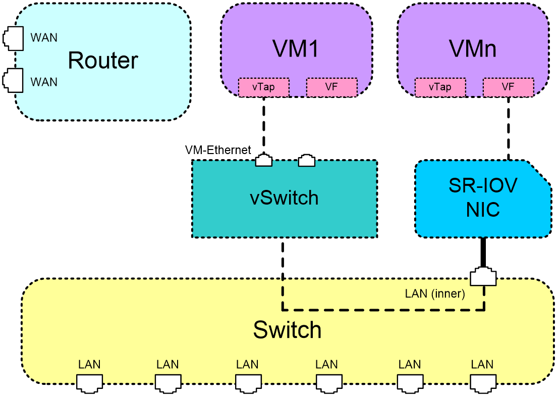
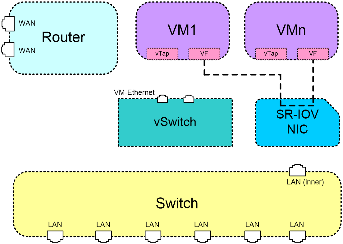
Figure 4 illustrates the forwarding path for the traffic between the VF interfaces of two VMs. The SR-IOV NIC forwards the traffic.
Figure 4 VF-VF traffic forwarding
VM-WAN traffic forwarding
Figure 5 illustrates the forwarding path for the traffic from a vTap interface on a VM to a WAN port on the Router module.
1. The vTap interface forwards the traffic to the vSwitch.
2. The vSwitch forwards the traffic to the Router module.
3. The Router module forwards the traffic to the WAN port.
The path of WAN-to-vTap traffic forwarding is the reverse of the vTap-to-WAN traffic forwarding path.
Figure 5 vTap-WAN traffic forwarding

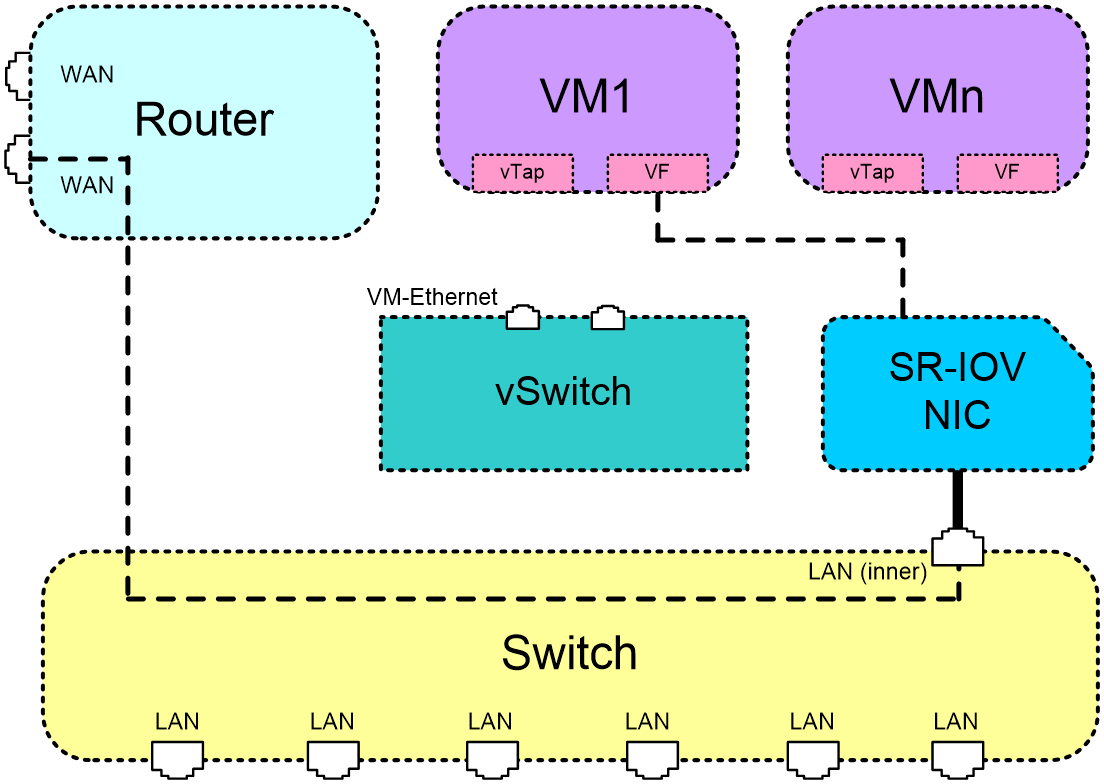
Figure 6 illustrates the forwarding path for the traffic from a VF interface on a VM to a WAN port on the device.
1. The SR-IOV NIC forwards the traffic to the Switch module through the LAN (inner) port.
2. The Switch module forwards the traffic to the Router module.
3. The Router module forwards the traffic to the WAN port.
The path of WAN-to-VF traffic forwarding is the reverse of the VF-to-WAN traffic forwarding path.
Figure 6 VF-WAN traffic forwarding
VM-LAN traffic forwarding
Figure 7 illustrates the forwarding path for the traffic from a vTap interface on a VM to a LAN port on the device.
1. The vTap interface forwards the traffic to the vSwitch.
2. The vSwitch forwards the traffic to the Switch module.
3. The Switch module forwards the traffic to the LAN port.
The path of LAN-to-vTap traffic forwarding is the reverse of the vTap-to-LAN traffic forwarding path.
Figure 7 vTap-LAN traffic forwarding
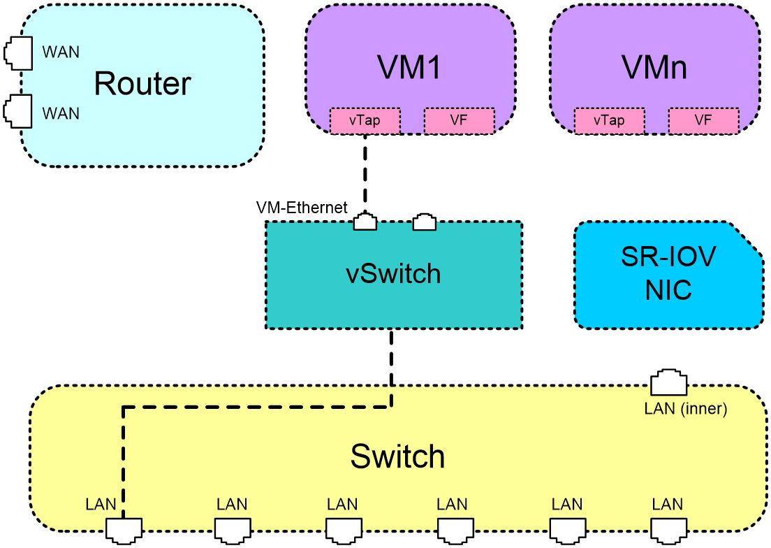
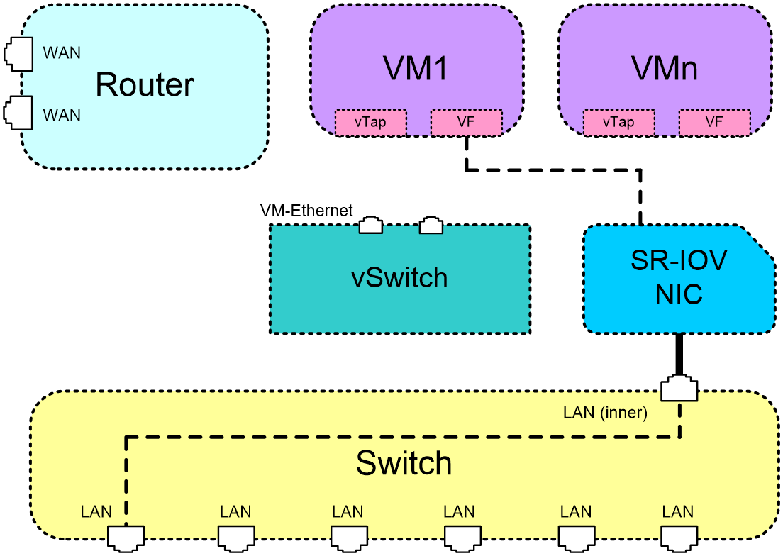
Figure 8 illustrates the forwarding path for the traffic from a VF interface on a VM to a LAN port on the device. The SR-IOV NIC forwards the traffic to the Switch module. Then, the Switch module forwards the traffic to the LAN port.
The path of LAN-to-VF traffic forwarding is the reverse of the VF-to-LAN traffic forwarding path.
Figure 8 VF-LAN traffic forwarding
Restrictions: Hardware compatibility with VMs
Only the following MSR routers support VMs:
· MSR3610-I-DP.
· MSR3610-I-XS.
· MSR3610-IE-DP.
· MSR3610-IE-XS.
· MSR3610-IE-ES.
· MSR3610-IE-EAD.
VM configuration tasks at a glance
To configure and manage VMs, perform the following tasks:
¡ Removing a disk or CD-ROM from a VM
¡ Specifying a boot order number for a disk
¡ Setting the physical NIC network mode for VMs
¡ Adding an SR-IOV NIC to a VM
¡ Setting the forwarding mode of a physical NIC
¡ Specifying a VLAN for a VF interface
¡ Removing an SR-IOV NIC from a VM
¡ Specifying a VLAN for a vTap NIC
¡ Removing a vTap NIC from a VM
¡ Allocating CPU cores to the VM plane
¡ Allocating vCPU cores to a VM
¡ Binding vCPU cores to physical CPU cores
¡ Setting the minimum amount of physical memory available for the Comware system
¡ Configuring VNC parameters for remote VM login
Installing a VM
About this task
The following VM installation methods are available on the device:
· Install a VM by using a .pkg file—You can bulk-install VMs by using a .pkg VM file. A .pkg file contains all files that make up a VM. All VMs created from a .pkg file have the same parameter settings as the source VM, including their guest OS, CPU, and memory settings. After a VM is installed, you can tune its settings as needed.
· Install a VM by manually specifying its parameters—You can install VMs by specifying VM parameters at the CLI of the device. Each VM has its own parameter settings, including the guest OS, CPU, and memory settings.
Restrictions and guidelines
If you are using the VM to provide H3C vFW services, use the following guidelines when you specify memory for the VM:
· If the vFW requires only one CPU core, allocate 2 GB of memory to the VM.
· If the vFW requires two CPU cores, allocate 4 GB of memory to the VM.
· If the vFW requires four CPU cores, allocate 8 GB of memory to the VM.
Prerequisites
If you are installing a VM by manually specifying its parameters, use the create-disk command to create a disk for the VM as described in "Adding a disk to a VM."
If you are using a .pkg file to install a VM, export an existing .pkg file as described in "Exporting a VM." If a USB flash drive is used to store the .pkg file, make sure the file system format of the USB flash drive is EXT4.
Procedure
1. Enter system view.
system-view
2. Enter VMM view.
vmm
3. Install a VM. Choose one of the following methods:
¡ Install a VM by using a local .pkg file.
install vm-pkg pkg-path
¡ Install a VM by using a .pkg file stored on a USB flash drive. First, insert the USB flash drive into the device. Then, reboot the device. The VM is installed on the device after the reboot.
Make sure the .pkg file is stored in the VmImages folder at the root directory of the USB flash drive. The folder name is case sensitive.
¡ Install a VM based on the specified parameters.
In passthrough mode:
install vm-name vm-name vcpu vcpu-count memory size vncport vncport disk disk-file format { raw | qcow2 } disk-bus { ide | virtio } [ cdrom cdrom-file ] [ vnic { vtap [ mac mac-address ] [ vlan vlan-id ] | sriov pf pfid } ]
In SR-IOV share mode:
install vm-name vm-name vcpu vcpu-count memory size vncport vncport disk disk-file format { raw | qcow2 } disk-bus { ide | virtio } [ cdrom cdrom-file ] [ vnic { vtap [ mac mac-address ] [ vlan vlan-id ] | sriov pf pfid vf vfid [ vlan vlan-id ] } ]
Starting a VM
About this task
For a VM to start successfully, you must make sure the system has sufficient memory. In addition to the memory for VMs, you must also make sure sufficient memory is available for the VM plane to run.
If system memory becomes insufficient while it is running, the system automatically stops the VM that uses the most memory.
Prerequisites
Make sure the VM you want to start has been created on the device and the system has sufficient memory to start the VM.
Procedure
1. Enter system view.
system-view
2. Enter VMM view.
vmm
3. Start a VM.
start vm vm-name
Resizing a VM
After you install a VM, you can resize the VM as needed by adding or removing its resources such as disks and memory.
Adding a disk to a VM
About this task
Disks for VMs are in the form of disk files. You add a disk to a VM by associating the disk file with the VM.
A VM supports the following bus types of disks:
· IDE—IDE disks and CD-ROMs share disk drive names hda, hdb, hdc, and hdd. The VM randomly assigns a drive name to an IDE disk or CD-ROM.
· Virtio—The drive names of virtio disks are vda, vdb, vdc, and vdd. The VM randomly assigns a drive name to a virtio disk.
A VM supports a maximum of four disks for each bus type.
Restrictions and guidelines
If you perform this task on a running VM, you must restart the VM for the configuration to take effect. If you perform this task on a stopped VM, the configuration takes effect after you start the VM.
After you add a disk to a VM, you must partition and format that disk on the VM before you can use it.
You can mount only one disk to a vFW VM.
When a VM is deployed, the VM automatically assigns a boot order number of 1 to its boot disk. To change the boot disk, you can perform the following operations:
1. (Optional.) Add a new disk to the VM.
2. Modify the boot order number of the original boot disk.
3. Assign the new boot disk a boot order number that has higher priority than that of the original boot disk.
For more information, see "Specifying a boot order number for a disk." To view the disk boot order, use the display vmdisklist command.
Procedure
1. Enter system view.
system-view
2. Enter VMM view.
vmm
3. Create a VM disk.
create-disk disk-file size size format { raw | qcow2 }
4. Add the disk to a VM.
add disk vm vm-name format { raw | qcow2 } disk-file path-file disk-bus { ide | virtio }
Removing a disk or CD-ROM from a VM
Restrictions and guidelines
If you perform this task on a running VM, you must restart the VM for the configuration to take effect. If you perform this task on a stopped VM, the configuration takes effect after you start the VM.
Removing a disk or CD-ROM from a VM does not delete the disk or delete the image files uploaded by the CD-ROM. To release storage space, you must use the delete command to manually delete the disk or the image files. For more information, see file system management in Fundamentals Configuration Guide.
Procedure
1. Enter system view.
system-view
2. Enter VMM view.
vmm
3. Remove a disk or CD-ROM from a VM.
delete disk vm vm-name target target
Adding a CD-ROM
About this task
The CD-ROMs and IDE disks share drive names hda, hdb, hdc, and hdd. When you add a CD-ROM or IDE disk to a VM, the VM randomly assigns a drive name to the CD-ROM or IDE disk.
Restrictions and guidelines
If you perform this task on a running VM, you must restart the VM for the configuration to take effect. If you perform this task on a stopped VM, the configuration takes effect after you start the VM.
Before using a newly added CD-ROM, specify a boot order number for it. CD-ROMs that contain operating system image files always have higher boot priority that those containing hardware driver image files. The same type of CD-ROMs boot according to the priority of their boot order numbers.
If you do not change the boot disk or uninstall the images of a CD-ROM after the CD-ROM is installed, the CD-ROM will no longer be used for booting.
When a VM is deployed, the VM automatically assigns a boot order number of 8 to the CD-ROM that contains the operating system image file. To replace the operating system images, perform the following operations:
1. Add a new CD-ROM that contains the new operating system image file.
2. Set the boot order of the new CD-ROM to take precedence over that of the original CD-ROM.
3. (Optional.) Add a new hard disk as the boot disk of the VM.
Alternatively, you can remove the CD-ROM that contains the current operating system image file and add the CD-ROM that contains the new operating system image file to the VM.
For more information about boot order configuration, see "Specifying a boot order number for a disk." To view the disk boot order, use the display vmdisklist command.
Procedure
1. Enter system view.
system-view
2. Enter VMM view.
vmm
3. Add a CD-ROM.
add cdrom vm vm-name cdrom-file cdrom-file
Specifying a boot order number for a disk or CD-ROM
About this task
Perform this task to specify a boot order number for a disk or CD-ROM. The lower the number, the higher the boot priority.
Restrictions and guidelines
To ensure that a VM can start, make sure no disk or CD-ROM has the same boot order number as the disk or CD-ROM used to boot the VM.
If you perform this task on a running VM, you must restart the VM for the configuration to take effect. If you perform this task on a stopped VM, the configuration takes effect after you start the VM.
Procedure
1. Enter system view.
system-view
2. Enter VMM view.
vmm
3. Specify a boot order number for a disk or CD-ROM.
set bootorder vm vm-name target target order-number
Adding a physical device
About this task
For a VM and a physical device to transfer files and data between them, perform this task to pass through the physical device to the VM.
Restrictions and guidelines
To add a physical device to a VM deployed in a version that does not support USB device pass-through, first perform the following tasks:
1. Execute the uninstall vm command to uninstall the VM.
2. Execute the install vm-name command to reinstall the VM. Do not change the disk file path when you reinstall the VM.
For the USB type, the device can pass through only storage and serial devices to VMs, and you cannot extend interfaces to add more physical devices. If a USB device is absent, you can specify its vendor ID and product ID to add it. After the USB device is installed, the VM can use it directly.
If you specify the PCI serial type, you can add only the SIC-4RS interface module.
If you perform this task on a running VM, you must restart the VM for the configuration to take effect. If you perform this task on a stopped VM, the configuration takes effect after you start the VM.
Procedure
1. Enter system view.
system-view
2. Enter VMM view.
vmm
3. Add a physical device to a VM.
add hostdev vm vm-name type type slot slot-number [ index index-number [ vid vid-id pid pid-id ] ]
Removing a physical device
About this task
Perform this task to remove a physical device from a VM.
Restrictions and guidelines
If you perform this task on a running VM, you must restart the VM for the configuration to take effect. If you perform this task on a stopped VM, the configuration takes effect after you start the VM.
Procedure
1. Enter system view.
system-view
2. Enter VMM view.
vmm
3. Remove a physical device from a VM.
delete hostdev vm vm-name type type slot slot-number [ index index-number ]
Setting the physical NIC network mode for VMs
Restrictions and guidelines
For the configuration to take effect, you must save the configuration and reboot the device.
To ensure that VMs can start up after the device reboots, make sure the NIC interfaces added to VMs are the interfaces required by the configured NIC network mode.
Procedure
1. Enter system view.
system-view
2. Set the VM network mode.
vm network-mode { passthrough | sr-iov }
By default, the passthrough mode is used.
Adding an SR-IOV NIC to a VM
About this task
Perform this task to allocate an SR-IOV NIC to a VM by specifying the MAC address of a PF or VF.
Restrictions and guidelines
Make sure the NIC interfaces added to VMs are the interfaces required by the configured NIC network mode.
For an SR-IOV NIC to operate on a VM, you must install an SR-IOV NIC driver on the VM.
If you perform this task on a running VM, you must restart the VM for the configuration to take effect. If you perform this task on a stopped VM, the configuration takes effect after you start the VM.
Procedure
1. Enter system view.
system-view
2. Enter VMM view.
vmm
3. Add an SR-IOV NIC to a VM. Choose one of the following tasks:
¡ In passthrough mode, add a PF interface to a VM.
add sriov vm vm-name pf pfid
¡ In SR-IOV share mode, add a VF interface to a VM.
add sriov vm vm-name pf pfid vf vfid [ vlan vlan-id ]
Setting the forwarding mode of a physical NIC
Restrictions and guidelines
Perform this task only when physical NICs operate in SR-IOV share mode.
Use MAC forwarding mode if a physical NIC does not check the VLAN tags of packets, for example, when a VM uses a vFW subinterface to communicate with a physical NIC.
To use MAC forwarding mode, configure subinterfaces on VMs in advance. For more information about subinterface configuration, see Ethernet interface configuration in Interface Configuration Guide.
Procedure
1. Enter system view.
system-view
2. Enter VMM view.
vmm
3. Set the forwarding mode of a physical NIC.
set sriov pf pfid mode { vlan | mac }
By default, physical NICs operate in VLAN forwarding mode.
Specifying a VLAN for a VF interface
Restrictions and guidelines
This feature is supported only in SR-IOV share mode.
Procedure
1. Enter system view.
system-view
2. Enter VMM view.
vmm
3. Specify a VLAN for a VF interface.
set sriov pf pfid vf vfid vlan vlan-id
4. Remove a VF interface from its VLAN.
undo set sriov pf pfid vf vfid vlan [ vlan-id ]
Removing an SR-IOV NIC from a VM
About this task
Remove a PF or VF from a VM to remove an SR-IOV NIC from that VM.
Restrictions and guidelines
If you perform this task on a running VM, you must restart the VM for the configuration to take effect. If you perform this task on a stopped VM, the configuration takes effect after you start the VM.
Prerequisites
Use the display vminterface command to obtain the ID of the PF or VF to be removed.
Procedure
1. Enter system view.
system-view
2. Enter VMM view.
vmm
3. Remove an SR-IOV NIC from a VM. Choose one of the following tasks:
¡ In passthrough mode, remove a PF interface from a VM.
delete sriov vm vm-name pf pfid
¡ In SR-IOV share mode, remove a VF interface from a VM.
delete sriov vm vm-name pf pfid vf vfid
Adding a vTap NIC to a VM
About this task
The Comware system has reserved eight MAC addresses for vTap NICs. When you add a vTap NIC to a VM, select a MAC address to uniquely identify it.
Restrictions and guidelines
You can add a vTap NIC only to one VM. To display the MAC addresses of NICs that have been added to a VM, use the display vminterface command.
If you perform this task on a running VM, you must restart the VM for the configuration to take effect. If you perform this task on a stopped VM, the configuration takes effect after you start the VM.
Procedure
1. Enter system view.
system-view
2. Enter VMM view.
vmm
3. Add a vTap NIC to a VM.
add vtap vm vm-name mac mac-address [ vlan vlan-id ]
Specifying a VLAN for a vTap NIC
About this task
Prerequisites
Use the display vminterface command to obtain the MAC address of the vTap NIC.
Procedure
1. Enter system view.
system-view
2. Enter VMM view.
vmm
3. Specify a VLAN for the vTap NIC of a VM.
set vtap vm vm-name mac mac-address vlan vlan-id
Removing a vTap NIC from a VM
Restrictions and guidelines
If you perform this task on a running VM, you must restart the VM for the configuration to take effect. If you perform this task on a stopped VM, the configuration takes effect after you start the VM.
Procedure
1. Enter system view.
system-view
2. Enter VMM view.
vmm
3. Remove a vTap NIC from a VM.
delete vtap vm vm-name mac mac-address
Allocating CPU cores to the VM plane
About this task
Functionalities of the system are categorized into the control, data, and VM planes. The virtualization functions run on the VM plane.
By default, the control plane is allocated one physical CPU core, the data plane is allocated one physical CPU core, and the VM plane is allocated the remaining physical CPU cores.
To change the number of physical CPU cores assigned to the VM plane, perform this task.
Restrictions and guidelines
For the configuration in this task to take effect, you must save the configuration and reboot the device.
After you modify the number of CPU cores allocated to the VM plane, you must reallocate vCPU cores to VMs and bind vCPU cores to physical CPU cores. For the reallocation and binding to take effect on a VM, you must restart the VM.
Procedure
1. Enter system view.
system-view
2. Allocate physical CPU cores to the VM plane.
set vcpu-pool vcpu-number
Allocating vCPU cores to a VM
Restrictions and guidelines
If you set the number of vCPU cores allocated to a VM to 0, the VM will be inaccessible at the next startup. To access the VM, you must reallocate vCPU cores to the VM.
If you perform this task on a running VM, you must restart the VM for the configuration to take effect. If you perform this task on a stopped VM, the configuration takes effect after you start the VM.
Procedure
1. Enter system view.
system-view
2. Enter VMM view.
vmm
3. Allocate vCPU cores to a VM.
set vcpu vm vm-name vcpu-count vcpu-count
Binding vCPU cores to physical CPU cores
About this task
Perform this task to bind the vCPU cores of a VM to physical CPU cores on the device.
Restrictions and guidelines
If you bind multiple vCPU cores of a VM to only one physical CPU core, the VM might fail to start up because of CPU resource conflict. As a best practice to ensure correct VM startup, bind the vCPU cores to different physical CPU cores.
If you perform this task on a running VM, you must restart the VM for the configuration to take effect. If you perform this task on a stopped VM, the configuration takes effect after you start the VM.
Procedure
1. Enter system view.
system-view
2. Enter VMM view.
vmm
3. Bind a vCPU core on a VM to a physical CPU core.
set vcpupin vm vm-name vcpuindex vcpuindex cpuindex cpuindex
Setting the minimum amount of physical memory available for the Comware system
Hardware and feature compatibility
This feature is supported only by the following routers:
· MSR3610-I-DP.
· MSR3610-I-XS.
· MSR3610-IE-DP.
· MSR3610-IE-XS.
Restrictions and guidelines
Make sure the Comware system is allocated a minimum of 2 GB of physical memory. In addition, the amount of physical memory allocated to the Comware system cannot exceed (the total amount of physical memory on the device - 2) GB.
The amount of physical memory available for the Comware system equals the total amount of physical memory on the device minus the amount of physical memory occupied by all VMs. As a best practice to avoid memory conflicts, set the minimum amount of physical memory available for the Comware system to a proper value.
For the configuration to take effect, you must save the configuration and reboot the device.
Procedure
1. Enter system view.
system-view
2. Enter VMM view.
vmm
3. Set the minimum amount of physical memory available for the Comware system.
set comware-memory size
By device, a minimum of 3 GB of physical memory is available for the Comware system.
Allocating memory to a VM
Restrictions and guidelines
To ensure that a VM can operate, make sure the VM is allocated a minimum of 512 MB of memory.
If you perform this task on a running VM, you must restart the VM for the configuration to take effect. If you perform this task on a stopped VM, the configuration takes effect after you start the VM.
Procedure
1. Enter system view.
system-view
2. Enter VMM view.
vmm
3. Allocate memory to a VM.
set memory vm vm-name size size
Maintaining a VM
Configuring VNC parameters for remote VM login
About this task
To remotely access the desktop of a VM from a VNC viewer (or client), perform this task.
When the VM is running, you can access the VM desktop from a VNC viewer (or client) by using the VNC server IP address and VNC port number. The VNC server IP address is the IP address of a Layer 3 interface or a VLAN interface on the device.
Restrictions and guidelines
If you perform this task on a running VM, you must restart the VM for the configuration to take effect. If you perform this task on a stopped VM, the configuration takes effect after you start the VM.
Procedure
1. Enter system view.
system-view
2. Enter VMM view.
vmm
3. Set the VNC port number of the VM.
set vnc vm vm-name vncport vncport
4. Set the VNC login password of the VM.
set vnc vm vm-name setpasswd password
5. Set the IP address for accessing the VM.
set vnc vm vm-name listen ip-address
6. (Optional.) Delete the VNC login password on the VM.
set vnc vm vm-name delpasswd
Enabling VM auto-start
About VM auto-start
Perform this task to enable a VM to start up automatically when the device starts.
Procedure
1. Enter system view.
system-view
2. Enter VMM view.
vmm
3. Enable VM auto-start.
autostart vm vm-name
By default, VM auto-start is disabled.
Suspending a VM
About this task
Perform this task to suspend a VM. The VM will then be placed in Paused state.
Procedure
1. Enter system view.
system-view
2. Enter VMM view.
vmm
3. Suspend a VM.
suspend vm vm-name
Resuming a suspended VM
1. Enter system view.
system-view
2. Enter VMM view.
vmm
3. Resume a suspended VM.
resume vm vm-name
Stopping a VM
About this task
When the Comware system reboots, the system automatically attempts to stop all hosted VMs securely within 6 minutes. If VMs are operating incorrectly, it will take 6 minutes to stop each VM. If the system fails to stop a VM within 6 minutes, it will force that VM down.
Perform this task to manually stop a VM.
Restrictions and guidelines
|
|
CAUTION: A force stop might cause data loss. Do not force a VM down unless necessary. |
If a VM fails to stop because of an abnormal process, access the VM, manually close the process, and retry the stop operation. If the stop operation still fails, force the VM down.
If the VM does not have an operating system, you must specify the force keyword to force it down.
Procedure
1. Enter system view.
system-view
2. Enter VMM view.
vmm
3. Stop a VM.
stop vm vm-name [ force ]
Backing up a VM
About this task
Perform this task to back up a VM to a .vmb file in the specified path.
Restrictions and guidelines
Make sure the file path is correct and the target storage medium has sufficient storage space.
If a USB flash drive is used to store the backup file, make sure the file system format of the USB flash drive is EXT4.
Prerequisites
You must stop a VM by using the stop vm command before you can back up it.
Procedure
1. Enter system view.
system-view
2. Enter VMM view.
vmm
3. Back up a VM.
backup vm vm-name backup-path
Restoring a VM
About this task
Perform this task to restore a VM by using a .vmb backup file.
Procedure
1. Enter system view.
system-view
2. Enter VMM view.
vmm
3. Restore a VM by using a .vmb backup file.
restore pakagepath backup-image-path
Exporting a VM
About this task
Perform this task to export a VM to a .pkg file in the specified path.
Restrictions and guidelines
Make sure you have access permissions to the target path and the target path has sufficient storage space.
If the .pkg file is saved on a USB flash drive, make sure the file system format of the USB flash drive is EXT4.
Prerequisites
You must stop a VM by using the stop vm command before you can export it.
Procedure
1. Enter system view.
system-view
2. Enter VMM view.
vmm
3. Export a VM.
export vm vm-name pkg-path
Uninstalling a VM
Restrictions and guidelines
After you uninstall a VM, the hard disks allocated to the VM still retain the VM operating system image files and running data files. To release storage space, you must use the delete command to manually delete the hard disks. For more information about deleting hard disks, see file system management in Fundamentals Configuration Guide.
Prerequisites
You must stop a VM by using the stop vm command before you can uninstall it.
Procedure
1. Enter system view.
system-view
2. Enter VMM view.
vmm
3. Uninstall a VM.
uninstall vm vm-name
Display and maintenance commands for VMs
Execute display commands in any view.
|
Task |
Command |
|
Display the minimum amount of physical memory available for the Comware system. |
display comware-memory size |
|
Display the physical devices available to VMs. |
display hostdev |
|
Display physical NIC information in passthrough mode. |
display passthrough |
|
Display physical NIC information in SR-IOV share mode. |
display sriov |
|
Display the number of CPU cores allocated to VMs. |
display vcpu-pool |
|
Display the VNC port number of a VM. |
display vncport vm vm-name |
|
Display detailed information about a VM. |
display vm [ vm-name [ static-configuration ] ] |
|
Display the physical NIC network mode. |
display vm-network-mode |
|
Display the CPU usage of a VM. |
display vmcpu-usage vm vm-name |
|
Display the bindings between vCPU cores and physical CPU cores for a VM. |
display vmcpupin [ vm vm-name ] |
|
Display disk usage information about a VM. |
display vmdisk-usage vm vm-name |
|
Display disk or CD-ROM information. |
display vmdisklist [ vm vm-name ] |
|
Display the physical devices attached to VMs. |
display vmhostdev [ vm vm-name ] |
|
Display network interface information about a VM. |
display vminterface [ vm vm-name ] |
|
Display the VM list. |
display vmlist |
|
Display the memory usage of a VM. |
display vmmem-usage vm vm-name |
