- Table of Contents
- Related Documents
-
| Title | Size | Download |
|---|---|---|
| 01-text | 8.65 MB |
Contents
About H3C Workspace desktop management software
About H3C Workspace desktop management software
Installation procedure at a glance
Preparing for the installation of Space Console
Obtaining the ISO image file of Space Console
Using the Linux dd command to build a USB bootable drive
Using the Rufus tool to build a USB bootable drive
Selecting the component to install
Verifying the software versions
Verifying the Workspace version
Verifying installation of Workspace components
Configuring and accessing Space Console
Configuring a management IP address
Accessing the Workspace self-service system (office scenario)
Deploying the system in compute virtualization mode
Deploying the system in HCI mode
Installing and deploying Workspace clients in the office scenario
Obtaining the installation packages
Performing automatic client installation
Installing the client manually (Windows OS)
Installing a client manually (SpaceOS/UOS)
Installing and deploying the IDV client
Installing and deploying the VOI client
Installing and deploying Learningspace clients in the education scenario
Installing the Learningspace student client
Installing the Learningspace student client on a VDI endpoint
Installing the Learningspace student client on a VOI endpoint
Installing the Learningspace teacher client
Obtaining the installation package
Deploying a VDI student endpoint
Deploying a VOI student endpoint
Troubleshooting cloud desktop installation
Black screen error occurs during Space Console installation
Uploading the client installation package
Uninstalling the VDI Workspace client manually
Uninstalling the client on a Windows endpoint
Uninstalling the client on a SpaceOS or UOS endpoint
Obtaining the installation package
Installing SpaceAgent on a Windows endpoint
Installing SpaceAgent on a SpaceOS or UOS endpoint
Uninstalling SpaceAgent on a Windows endpoint
Uninstalling SpaceAgent from a SpaceOS or UOS endpoint
Uninstalling a Learningspace client
Uninstalling a Learningspace client on a Windows endpoint
Uninstalling the Learningspace student client on a SpaceOS endpoint
Hardware requirements for a management server that can operate only as a management node
About H3C Workspace desktop management software
About H3C Workspace desktop management software
H3C Workspace desktop management software is a desktop virtualization solution developed based on virtual desktop infrastructure (VDI), intelligent desktop virtualization (IDV), and virtual OS infrastructure (VOI). With this software, you can move virtual desktop components including applications, OSs, and user data to a managed data center in the cloud for unified management and control. Users can access a desktop operating system from a thin client, fat client, mobile client, or PC as if they were using their own PC.
H3C Workspace desktop management software can be deployed for office, education (also called learning space), and hybrid office and education scenarios.
· Office scenario—Allows access to a cloud desktop or application from VDI, IDV, or VOI endpoints.
· Education scenario—Allows access to a class desktop from VDI or VOI endpoints for high-load services such as education, 3D modeling, and video processing.
· Hybrid office and education scenario—Allows access to office cloud desktops and applications from office clients and access to education cloud desktops and applications from education clients as needed.
The following figures show the typical architectures for the office and education scenarios, respectively.
Figure 1 H3C Workspace architecture (office scenario)
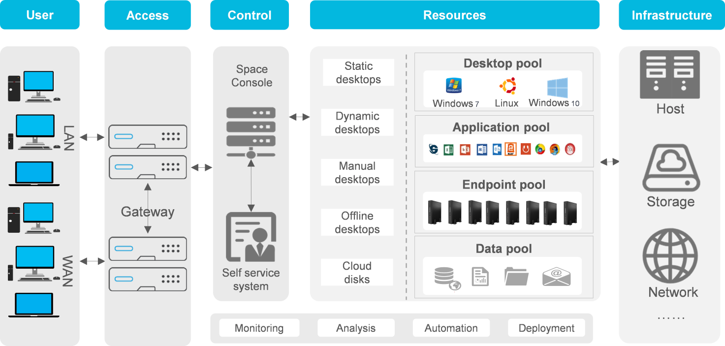
Figure 2 H3C Workspace architecture (education scenario)
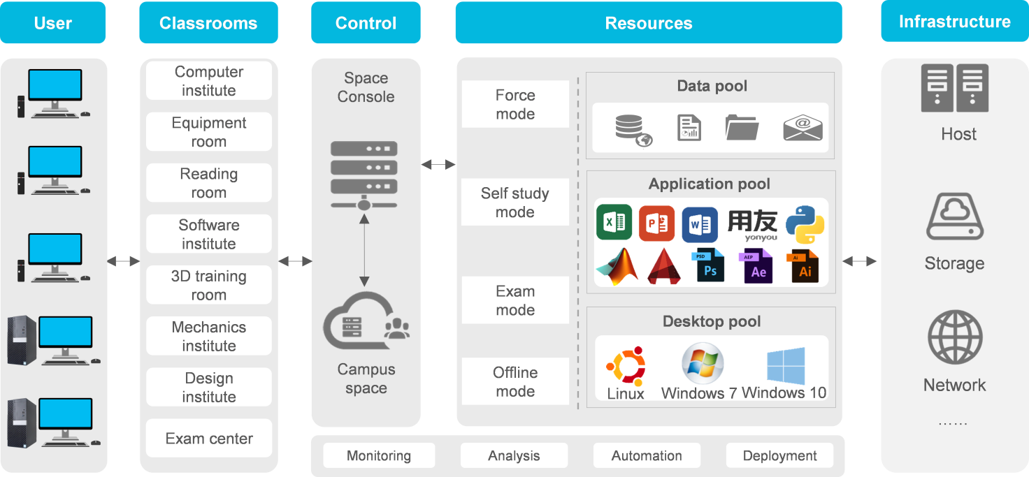
Components
H3C Workspace desktop system contains the following components:
· Space Console—Located at the controller layer to manage the entire system. With Space Console, you can move virtualized desktop components including applications, OSs, and user data to a managed data center in the cloud for unified management and control.
· Workspace cloud desktop clients in the office scenario:
¡ Workspace App—A client compatible with VDI endpoints for connecting to a VDI cloud desktop. After deploying it on a PC or thin client, you can transmit images on cloud desktops or map local devices on a PC or thin client to a VDI cloud desktop.
¡ Spacelauncher for IDV—A client running on an IDV endpoint. With the IDV client, users can use an IDV cloud desktop.
¡ Spacelauncher for VOI—A client running on a VOI endpoint. With the VOI client, users can use a VOI cloud desktop.
· Workspace cloud desktop clients in the education scenario:
¡ Learningspace_App teacher module—A client running on a VDI teacher endpoint, for example, a PC. Teachers can start or end a class, manage student clients, manage assignment collection, and run teaching management software. A teacher module supports one-key operations such as class starting and ending, remote startup, and remote shutdown for the convenience of teachers.
¡ Learningspace_App student module—A client running on a student endpoint, for example, a thin client. This client is compatible with VDI and VOI endpoints. Students can use this client to access class desktops.
· Workspace self-service system—This system is supported only in the office scenario. Users can request accounts or desktops through workflows in the system. The administrator approves the workflows and assigns resources to users.
Installation procedure at a glance
The installation of the H3C Workspace desktop system includes installation and initialization of Space Console and installation and deployment of H3C Workspace cloud desktop clients. The Workspace self-service system is automatically installed when Space Console is installed.
Table 1 describes the main tasks for the installation of Space Console and Workspace cloud desktop clients.
Table 1 H3C Workspace desktop system installation procedure at a glance
Preparing for the installation of Space Console
H3C Space Console supports the following deployment modes on hosts:
· Compute virtualization—Deploys only the virtualization management platform. Distributed storage is not deployed. It is suitable for scenarios where an external IP SAN or FC SAN is used for providing storage services. A minimum of one host is required.
· HCI—Deploys both the virtualization management platform and distributed storage. It is suitable for scenarios where hyper convergence of computing, storage, networking, and virtualization is required. A minimum of three hosts are required.
|
|
CAUTION: · You can deploy compute virtualization on hosts in the education scenario. · In the hybrid office & education scenario, add the servers for the office scenario and education scenario to different clusters. The configuration requirements for a server depend on its deployment scenario. |
Office scenario
Hardware requirements
Restrictions and guidelines
Follow these restrictions and guidelines when configuring the server to host Space Console for the office scenario.
· x86 and ARM servers are supported in the office scenario. To use an x86 server, make sure its CPUs support Intel virtualization technology (Intel-VT) or AMD Virtualization (AMD-V). To use an ARM server, make sure its CPUs support ARM VHE. For optimal migration compatibility, use same CPUs for the servers in a cluster.
· Configure the server with a memory size as large as possible.
· As a best practice, use GE or 10-GE NICs for the management network and service network and 10GE NICs for the storage network. For high link throughout and availability, configure link aggregation for the NICs.
· If you are not to connect the server to an external storage system, the total size of the data disks depends on the number of VMs and the disk size allocated to each VM. If you are to connect the server to an external storage network, the data disks are used for storing VM configuration files. See Table 2, Table 3, and Table 4 for the disk settings.
· To avoid VM service interruption caused by a power supply failure, configure two power supplies in 1+1 redundancy for the server.
· As a best practice, do not use HDDs to store system disk images for VMs because of the limited speed and other mechanical properties of HDDs. If you use HDDs to store VM system disk images, a startup storm might occur when a large number of virtual desktops start at the same time. If you have to use HDDs because of a limited budget, stagger scheduled startups for desktop pools or VMs. For information about scheduling the startup of desktop pools or VMs, see H3C Workspace Desktop Management Software User Manual.
· For automatic RAID setup and management, install the SAS system disks, SSD data disks, and HDD data disks in sequence in the slots in ascending order of slot number. If the disks are not installed in this order, you must set up RAID manually.
Compute virtualization deployment
A minimum of one server is required for compute virtualization deployment. Table 2 describes the hardware requirements for a server for compute virtualization deployment.
Table 2 Hardware requirements for a server (compute virtualization deployment)
|
Item |
Minimum requirements |
|
CPU |
Intel Xeon processor, 2.2 GHz base frequency. Kunpeng processor, 2.6 GHz base frequency. AMD EPYC processor, 2.3 GHz base frequency |
|
Memory |
8*32 GB |
|
System disks |
Two 600GB 10K RPM SAS HDDs set up in RAID 1 |
|
Data disks |
Three 960GB SATA SSDs set up in RAID 5 |
|
Two 4TB 7.2K RPM SATA HDDs set up in RAID 1 |
|
|
NICs |
One 4-port GE NIC |
For information about hardware requirements for VOI management servers in the office scenario, see Table 10, Table 11, and Table 12.
HCI deployment
· Three or more hosts
In HCI deployment mode, Space Control will be deployed on three or more H3C UIS-Desktop-50 or H3C UIS-Desktop-40 servers. Table 3 and Table 4 describe the hardware requirements for an H3C UIS-Desktop-50 and H3C UIS-Desktop-40 server for HCI deployment, respectively. An H3C UIS-Desktop-50 or H3C UIS-Desktop-40 server is preinstalled with Space Console. You can initialize the server upon its bootup without reinstalling Space Console.
Table 3 Hardware requirements for an H3C UIS-Desktop-50 server (HCI deployment)
|
Item |
Minimum requirements |
|
CPU |
Intel Xeon processor, 2.3 GHz base frequency. |
|
Memory |
10*32 GB. |
|
System disks |
Two 600GB 10K RPM SAS HDDs. As a best practice, configure the two disks in RAID 1. |
|
Data disks |
Two 480GB SATA SSDs, with each SSD configured in RAID 0. |
|
Eight 2TB 7.2K RPM SATA HDDs, with each HDD configured in RAID 0. |
|
|
NICs |
One 4-port GE NIC + one two-port 10-GE NIC. |
Table 4 Hardware requirements for an H3C UIS-Desktop-40 server (HCI deployment)
|
Item |
Minimum requirements |
|
CPU |
Intel Xeon processor, 2.2 GHz base frequency. |
|
Memory |
8*32 GB. |
|
System disks |
Two 600GB 10K RPM SAS HDDs. As a best practice, configure the two disks in RAID 1. |
|
Data disks |
One 480GB SATA SSD, with each SSD configured in RAID 0. |
|
Four 4 TB 7.2K or above RPM SATA HDDs, with each HDD configured in RAID 0. |
|
|
NICs |
One 4-port GE NIC + one two-port 10-GE NIC. |
· Two hosts
If only two hosts are available, you must configure also an external monitor node. A cloud endpoint or VM can be used as the external monitor node.
Software image files
Obtain the most recent software image file released from H3C. Table 5 describes the software image files.
Table 5 Software image files
|
Software image file |
Description |
|
H3C_WORKSPACE-version-centos-x86_64-AUTO.iso |
Automatic installation version for an x86 server, installed automatically with default settings. You can also select manual installation, which requires manual disk partitioning and node configuration during the installation process. |
|
H3C_WORKSPACE-version-centos-aarch64-AUTO.iso |
Automatic installation version for an ARM server, installed automatically with default settings. You can also select manual installation, which requires manual disk partitioning and node configuration during the installation process. |
|
H3C_Workspace-version-Clients.tar.gz |
Client installation package. |
Automatic installation automatically sets up RAID, partitions the system disk, and completes installation. If the server has been configured with RAID settings, the RAID settings will remain unchanged during installation. As a best practice, clear the existing RAID settings and set up RAID manually before installation to ensure that the RAID settings meet the requirements. If the SAS system disks, SSD data disks, and HDD data disks are installed in sequence in the slots in ascending order of slot number on the server, you are not required to set up RAID manually after clearing the existing RAID configuration.
Manual installation is typically used in scenarios that have special requirements for RAID or system disk partitions. Before installation, complete required configurations as planned.
The client installation package is a compressed package separated from the Space Console installation package. After deployment or upgrade of Space Console, upload the client installation package from Space Console.
|
|
IMPORTANT: Currently only the manual installation version of the software image file is supported for the installation of Space Console. |
|
|
NOTE: The Space Console installation procedure is similar for x86 and ARM servers. |
Education scenario
Hardware requirements
Primary and secondary education scenario
Table 6 Hardware requirements for an Intel server to host 20 to 50 lightly, medium loaded desktops
|
Item |
Minimum requirements |
|
CPU |
Intel Xeon processor 4210 (2*10 cores ), base frequency ≥ 2.2 GHz |
|
Memory |
8*16 GB |
|
System disk |
1*600 GB HDD (for installation of the operating system only). As a best practice, set up RAID 1 with two HDDs. |
|
Image file disk |
1*960 GB SSD |
|
Data disk |
As required |
|
NIC |
· A minimum of four GE network ports for a cluster with less than five servers · A minimum of two 10GE network ports for a cluster with five or more servers |
Table 7 Hardware requirements for an Intel server to host 25 to 60 heavily loaded desktops
|
Item |
Minimum requirements |
|
CPU |
Intel Xeon processor 4214R (2*12 cores), base frequency ≥ 2.2 GHz |
|
Memory |
10*16 GB |
|
System disk |
1*600 GB HDD (for installation of the operating system only). As a best practice, set up RAID 1 with two HDDs. |
|
Image file disk |
1*960 GB SSD |
|
Data disk |
As required |
|
NIC |
· A minimum of four GE network ports for a cluster with less than five servers · A minimum of two 10GE network ports for a cluster with five or more servers |
Table 8 Hardware requirements for a AMD server to host 30 to 60 heavily loaded desktops
|
Item |
Minimum requirements |
|
CPU |
AMD EPYC processor 7352 (2*24 cores), base frequency ≥ 2.3 GHz |
|
Memory |
10*16 GB |
|
System disk |
2*600 GB HDD set in RAID1 (for installation of the operating system only) |
|
Image file disk |
2*480 GB SSD set in RAID0 |
|
Data disk |
As required |
|
NIC |
· A minimum of four GE network ports for a cluster with less than five servers · A minimum of two 10GE network ports for a cluster with five or more servers |
Table 9 Hardware requirements for a AMD server to host 55 to 120 heavily loaded desktops
|
Item |
Minimum requirements |
|
CPU |
AMD EPYC processor 7502 (2*32 cores), base frequency ≥ 2.5 GHz |
|
Memory |
10*32 GB |
|
System disk |
2*600 GB HDD set in RAID1 (for installation of the operating system only) |
|
Image file disk |
4*480 GB SSD set in RAID0 |
|
Data disk |
As required |
|
NIC |
· A minimum of four GE network ports for a cluster with less than five servers · A minimum of two 10GE network ports for a cluster with five or more servers |
Table 10 Hardware requirements for a VOI management server that supports 120 heavily loaded desktops
|
Item |
Minimum requirements |
|
CPU |
i3-9100 3.6 GHz |
|
Memory |
16 GB |
|
System disk |
512GB SSD. As a best practice, set up RAID 1 with two SSDs. |
|
NIC |
One GE network port |
|
Item |
Minimum requirements |
|
CPU |
Intel Xeon processor 3260R (2*8 cores), base frequency ≥ 1.9 GHz |
|
Memory |
64 GB |
|
System disk |
1*600 GB HDD (for installation of the operating system only). As a best practice, set up RAID 1 with two HDDs. |
|
Image file disk |
1*480 GB SSD |
|
Data disk |
As required |
|
NIC |
· A minimum of four GE network ports for less than or equal to 200 desktops · A minimum of two 10GE network ports for more than 200 desktops |
|
Item |
Minimum requirements |
|
CPU |
Intel Xeon processor 4208 (2*8 cores), base frequency ≥ 2.1 GHz |
|
Memory |
128 GB |
|
System disk |
1*600 GB HDD (for installation of the operating system only). As a best practice, set up RAID 1 with two HDDs. |
|
Image file disk |
1*480 GB SSD |
|
Data disk |
As required |
|
NIC |
A minimum of four GE network ports and a minimum of two 10GE network ports |
Higher education scenario
Table 13 Hardware requirements for an Intel server to host 25 to 40 lightly, medium loaded desktops
|
Item |
Minimum requirements |
|
CPU |
Intel Xeon processor 4214R (2*12 cores), base frequency ≥ 2.4 GHz |
|
Memory |
Desktop memory*Desktop count*120% (a sufficient size) +32 GB (for Space Console) |
|
System disk |
2*600 GB HDDs (for installation of the operating system only). As a best practice, set up RAID 1 with the two HDDs. |
|
Image file disk |
2*480 GB SSDs. As a best practice, set up RAID 0 with the two SSDs. |
|
Data disk |
As required |
|
NIC |
· A minimum of four GE network ports for a cluster with less than four servers · A minimum of two 10GE network ports for a cluster with four or more servers |
Table 14 Hardware requirements for an Intel server to host 30 to 50 lightly, medium, and heavily loaded desktops
|
Item |
Minimum requirements |
|
CPU |
Intel Xeon processor 5218 (2*16 cores), base frequency ≥ 2.3 GHz |
|
Memory |
Desktop memory*Desktop count*120% (a sufficient size) +32 GB (for Space Console) |
|
System disk |
2*600 GB HDDs (for installation of the operating system only). As a best practice, set up RAID 1 with the two HDDs. |
|
Image file disk |
2*480 GB SSDs. As a best practice, set up RAID 0 with the two SSDs. |
|
Data disk |
As required |
|
NIC |
· A minimum of four GE network ports for a cluster with less than four servers · A minimum of two 10GE network ports for a cluster with four or more servers |
Table 15 Hardware requirements for an Intel server to host 40 to 60 lightly, medium, and heavily loaded desktops
|
Item |
Minimum requirements |
|
CPU |
Intel Xeon processor 6226R (2*16 cores), base frequency ≥ 2.9 GHz |
|
Memory |
Desktop memory*Desktop count*120% (a sufficient size) +32 GB (for Space Console) |
|
System disk |
2*600 GB HDDs (for installation of the operating system only). As a best practice, set up RAID 1 with the two HDDs. |
|
Image file disk |
2*480 GB SSDs. As a best practice, set up RAID 0 with the two SSDs. |
|
Data disk |
As required |
|
NIC |
· A minimum of four GE network ports for a cluster with less than four servers · A minimum of two 10GE network ports for a cluster with four or more servers |
Table 16 Hardware requirements for a AMD server to host 40 to 60 lightly, medium, and heavily loaded desktops
|
Item |
Minimum requirements |
|
CPU |
AMD EPYC processor 7502 (2*32 cores), base frequency ≥ 2.5 GHz |
|
Memory |
Desktop memory*Desktop count*120% (a sufficient size) +32 GB (for Space Console) |
|
System disk |
2*600 GB HDDs (for installation of the operating system only). As a best practice, set up RAID 1 with the two HDDs. |
|
Image file disk |
2*480 GB SSDs. As a best practice, set up RAID 0 with the two SSDs. |
|
Data disk |
As required |
|
NIC |
· A minimum of four GE network ports for a cluster with less than four servers · A minimum of two 10GE network ports for a cluster with four or more servers |
Table 17 Hardware requirements for a GPU server to host a maximum of 32 desktops (not rendering)
|
Item |
Minimum requirements |
|
CPU |
Intel Xeon processor 6226R (2*16 cores), base frequency ≥ 2.9 GHz |
|
Memory |
12*32 GB |
|
GPU |
M10*1 or T4*2 |
|
System disk |
1*600 GB HDD (for installation of the operating system only). As a best practice, set up RAID 1 with two HDDs. |
|
Image file disk |
1*480 GB SSD |
|
Data disk |
As required |
|
NIC |
· A minimum of four GE network ports for a cluster with less than four servers · A minimum of two 10GE network ports for a cluster with four or more servers |
Table 18 Hardware requirements for a GPU server to host 16 to 24 desktops (rendering)
|
Item |
Minimum requirements |
|
Maximum number of desktops |
Depends on video memory allocation. |
|
CPU |
Intel Xeon processor 6246R (2*16 cores), base frequency ≥ 3.4 GHz |
|
Memory |
12*32 GB or 16*32 GB, 16 to 24GB video memory for each GPU card |
|
GPU |
T4*2 or RTX6000*2 |
|
System disk |
1*600 GB HDD (for installation of the operating system only). As a best practice, set up RAID 1 with two HDDs. |
|
Image file disk |
1*480 GB SSD |
|
Data disk |
As required |
|
NIC |
· A minimum of four GE network ports for a cluster with less than four servers · A minimum of two 10GE network ports for a cluster with four or more servers |
|
|
IMPORTANT: Make sure the service nodes are the same in configuration. |
|
|
IMPORTANT: · In the education scenario, only x86 CPUs are supported, and the CPUs must support Intel virtualization technology (Intel-VT) or AMD Virtualization (AMD-V). For optimal migration compatibility, use same CPUs for the servers in a cluster. · Configure the server with a memory size as large as possible. · For automatic RAID setup and management, install the SAS system disks, SSD data disks, and HDD data disks in sequence in the slots in ascending order of slot number. If the disks are not installed in this order, you must set up RAID manually. · To avoid VM service interruption caused by a power supply failure, configure two power supplies in 1+1 redundancy for the server. |
Software image files
Obtain the most recent software image file released from H3C. Table 19 describes the software image files.
Table 19 Software images
|
Software image file |
Description |
|
H3C_Workspace-version-centos-x86_64-AUTO.iso |
Automatic installation version for an x86 server, installed automatically with default settings. You can also select manual installation, which requires manual disk partitioning and node configuration during the installation process. |
|
H3C_WORKSPACE-version-centos-aarch64-AUTO.iso |
Automatic installation version for an ARM server, installed automatically with default settings. You can also select manual installation, which requires manual disk partitioning and node configuration during the installation process. |
|
H3C_Workspace-version-Clients.tar.gz |
Client installation package. |
Automatic installation automatically sets up RAID, partitions the system disk, and completes installation. If the server has been configured with RAID settings, the RAID settings will remain unchanged during installation. As a best practice, clear the existing RAID settings and set up RAID manually before installation to ensure that the RAID settings meet the requirements. If the SAS system disks, SSD data disks, and HDD data disks are installed in sequence in the slots in ascending order of slot number on the server, you are not required to set up RAID manually after clearing the existing RAID configuration.
Manual installation is typically used in scenarios that have special requirements for RAID or system disk partitions. Before installation, complete required configurations as planned.
The client installation package is a compressed package separated from the Space Console installation package. After deployment or upgrade of Space Console, upload the client installation package from Space Console.
|
|
NOTE: The Space Console installation procedure is similar for x86 and ARM servers. |
Installing Space Console
Obtaining the ISO image file of Space Console
Space Console uses the H3C_WORKSPACE-version-centos-x86_64.iso ISO image file. The default installation mode is automatic installation, where the installation is completed automatically without human intervention. As a best practice, use auto installation. If you have special requirements for the installation, use manual installation. The following procedure uses manual installation.
You can install Space Console from a bootable USB drive or a virtual drive on the hosts. As a best practice, use a bootable USB drive to install Space Console on the hosts.
|
|
IMPORTANT: · To install Space Console from a virtual drive, use the KVM console to access the server and ensure stable and uninterrupted network connection during the installation process. · If you use two NVMe drives as system disks, configure RAID settings for the drives before installation (as a best practice, configure RAID 1 for the two NVMe drives), and use manual installation. · Prepare a USB drive with a minimum size of 16 GB in advance for building a bootable USB drive. |
Building a bootable USB drive
A server typically provides multiple USB ports. You can build the Space Console image file into a bootable USB drive by using the Linux dd command or the Rufus tool.
· For an ARM manual image file, use the Linux dd command to build a USB bootable drive.
· For an x86 manual image file, use the Rufus tool to build a USB bootable drive.
Using the Linux dd command to build a USB bootable drive
1. Prepare for building the Space Console image file into a bootable USB drive
a. Connect the USB drive to a terminal or PC running a Linux operating system.
b. Copy the ISO image file to the Linux system. Before copying, execute the md5sum xx.iso (xx.iso is the file name) command to ensure the integrity of the image file.
c. Execute the fdisk – l command to view the name of the USB drive.
2. Mount the USB drive on the Linux system manually.
Some desktop Linux systems mount the USB drive automatically. If the USB drive has been mounted automatically, you must execute the umount command and then the mount command to unmount and then mount the USB drive.
a. Execute the mount command to identify whether the USB drive has been mounted automatically.
In this example, the USB drive name is sdb.
[root@cvknode-32 ~]# mount | grep sdb
- If information as follows is displayed, the USB drive has been mounted automatically. Go to b.
/dev/sdb1 on /var/ftp type ext4 (rw,relatime,stripe=64,data=ordered)
- If no information is returned, the USB drive has been mounted manually. Go to step 3.
b. Execute the umount command to unmount the USB drive.
[root@cvknode-32 ~]# umount /dev/sdb1
c. Execute the mount command to mount the USB drive.
[root@cvknode-32 ~]# mount | grep sdb
3. Use the dd if=image name.iso of=/dev/USB drive name bs=1M command, for example, dd if=H3C_WORKSPACE-E1010-centos-x86_64.iso of=/dev/sdb bs=1M, to burn the ISO image file to the USB drive.
4. Execute the sync && sync command.
5. Remove the USB drive.
Using the Rufus tool to build a USB bootable drive
|
|
CAUTION: Rufus 3.11 cannot scan and load ISO images. As a best practice, use Rufus 3.9 or 3.10 to build a bootable USB drive. |
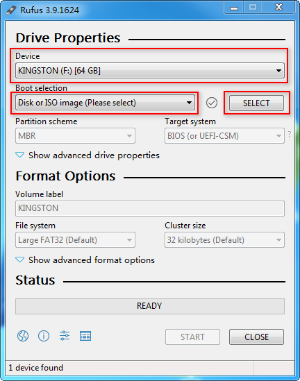
Rufus is free software for building bootable USB drives. It can be downloaded from the website: rufus.ie.
Figure 3 Rufus

To build a bootable USB drive:
1. Copy the ISO image file to the system. Before copying, execute the certutil –hashfile xx.iso MD5 (xx.iso is the file name) command to ensure the integrity of the image file.
2. Double-click the Rufus tool. Select the target USB drive from the Device list and Disk or ISO image (Please select) from the Boot selection list and then click SELECT.
Figure 4 Selecting the USB drive and ISO image booting
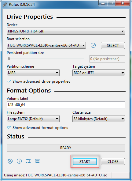
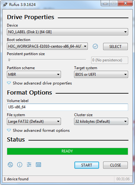
3. Select the H3C Workspace desktop ISO image file, and configure the other settings as required. Then click START.
Figure 5 Starting to build the bootable USB flash drive
4. On the ISOHybrid image detected window, select Write in DD image mode and then click OK.
Figure 6 Selecting to write in DD image node
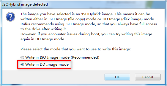
Figure 7 Building a bootable USB flash drive
Configuring BIOS settings
For more information about BIOS settings, see the user manual that comes with the server.
To configure BIOS settings:
1. Start the server and enter the BIOS setup utility.
2. Enable CPU virtualization (Intel Virtualization Technology).
3. Save the BIOS settings and quit the BIOS setup utility.
4. Restart the server.
Configuring RAID settings
Office scenario
If you use automatic installation, configure RAID settings as follows before installation:
· Compute virtualization deployment—Configure RAID settings manually. For the RAID settings, see Table 2.
· HCI deployment—Clear existing RAID settings and make sure the SAS system disks, SSD data disks, and HDD data disks are installed in sequence in the slots in ascending order of slot number.
If you use manual installation, configure RAID settings manually. See Table 2, Table 3, and Table 4 for the RAID settings.
Education scenario
For automatic RAID configuration, use automatic installation. Before installation, clear existing RAID settings and make sure the SAS system disks, SSD data disks, and HDD data disks are installed in sequence in the slots in ascending order of slot number.
For manual RAID configuration, first configure RAID settings manually and then use automatic or manual installation. For RAID settings, see "Hardware requirements."
Installing Space Console
Starting the installation
X86 server/Feiteng ARM server/cloud endpoint
1. Connect the bootable USB drive to a USB port on the server or cloud endpoint.
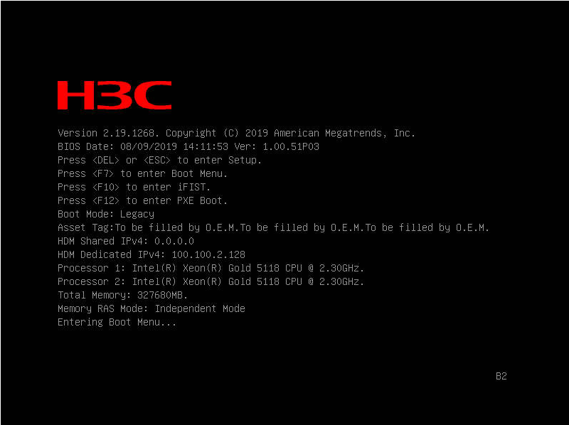
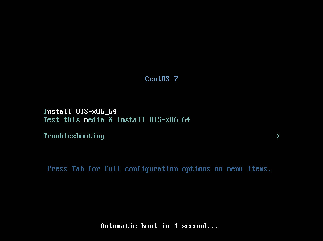
2. Start the server or cloud endpoint. On the system startup screen, press F7.
Figure 8 System startup screen
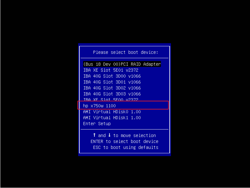
3. Select the USB drive as the boot device. In this example, hp x750w 1100 is selected.
Figure 9 Selecting the USB drive
|
|
CAUTION: · Do not set USB as the first boot option from the BIOS. With USB as the first boot option, the server will reinstall the system upon a restart if the USB drive is not removed from the server after the system is installed. · To prevent the USB drive from occupying the sda partition, remove the USB drive after the system is installed and before the system restarts. If the sda partition has been occupied, remove the USB drive and then reboot the system. |
4. On the installation option screen, select Install UIS-x86_64 to use manual installation.
Figure 10 Installation option screen
Kunpeng ARM server
1. Start the server, access the console, and select the driver bootup option.
2. Plug the USB drive into the USB port of the server.
3. Start the server.
VM
1. Create a VM with required specifications and mount the ISO image file to the virtual drive of the VM.
2. Start the VM. The installation option screen opens.
|
|
NOTE: For the procedure of creating a VM, mounting an ISO image file to the virtual drive of the VM, and starting the VM, see the user guide for the virtualization platform. |
Selecting the component to install
1. On the INSTALLATION SUMMARY page, click SOFTWARE SELECTION in the SOFTWARE area.
Figure 11 Installation summary page
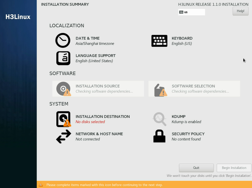
Figure 12 Selecting SOFTWARE SELECTION
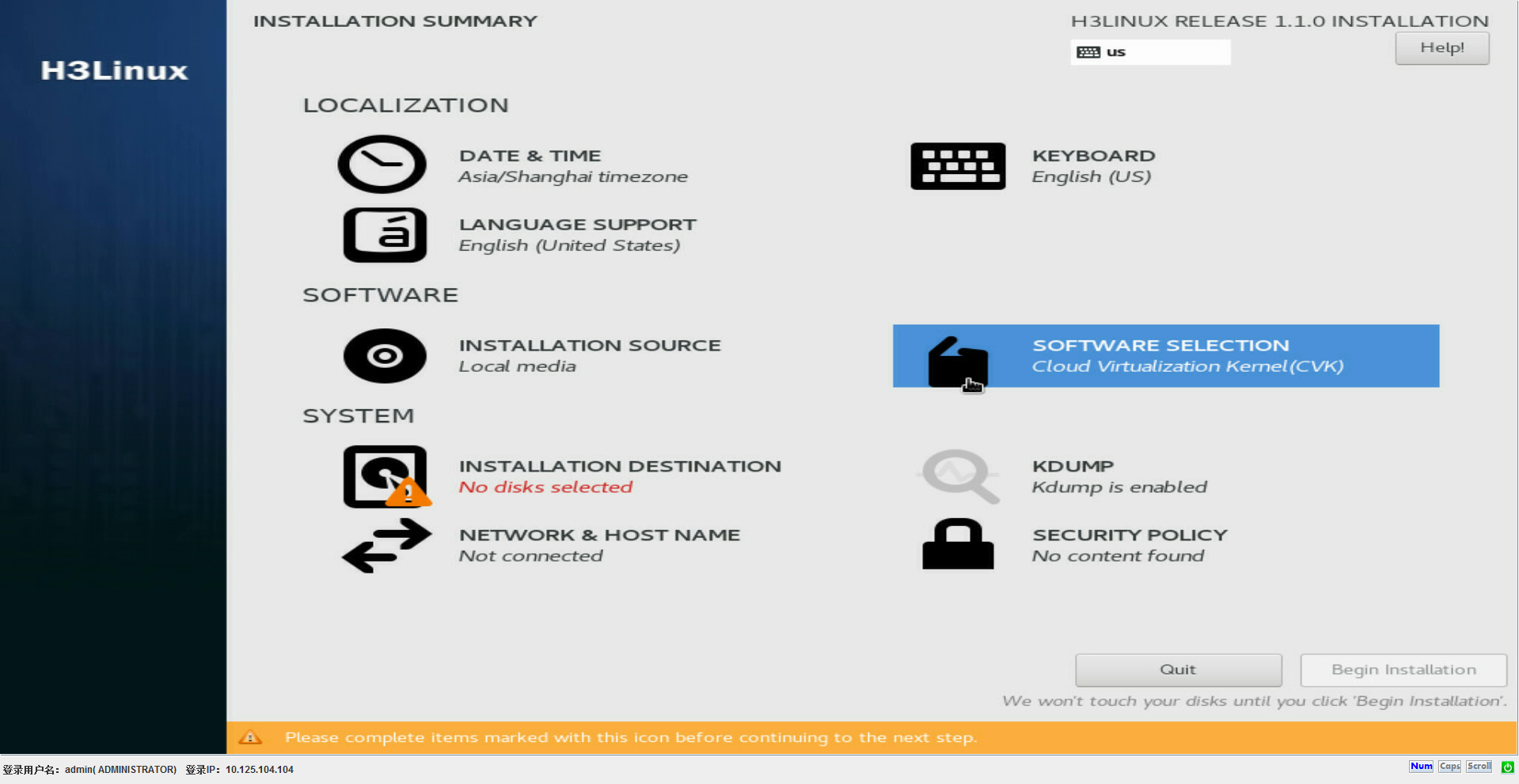
2. Select the Cloud Virtualization Manager(CVM)-English base environment based on the host role.
Figure 13 Selecting the component to install based on the host role
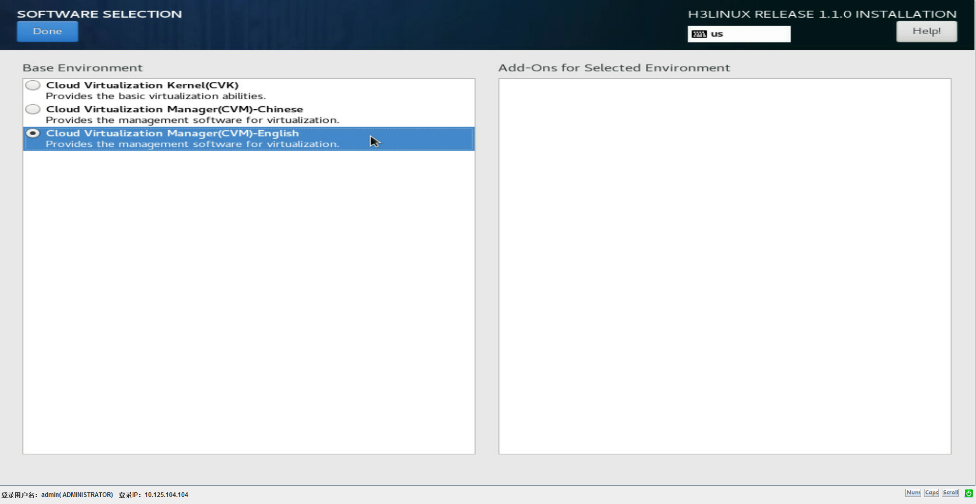
In the manual installation version, Cloud Virtualization Kernel(CVK) is selected by default. If the host is the management node, select Cloud Virtualization Manager(CVM)-English. If the host is a service node, keep the default selection. For stateful failover deployment, select Cloud Virtualization Manager(CVM)-English for both the primary and backup management hosts.
Selecting the system disk
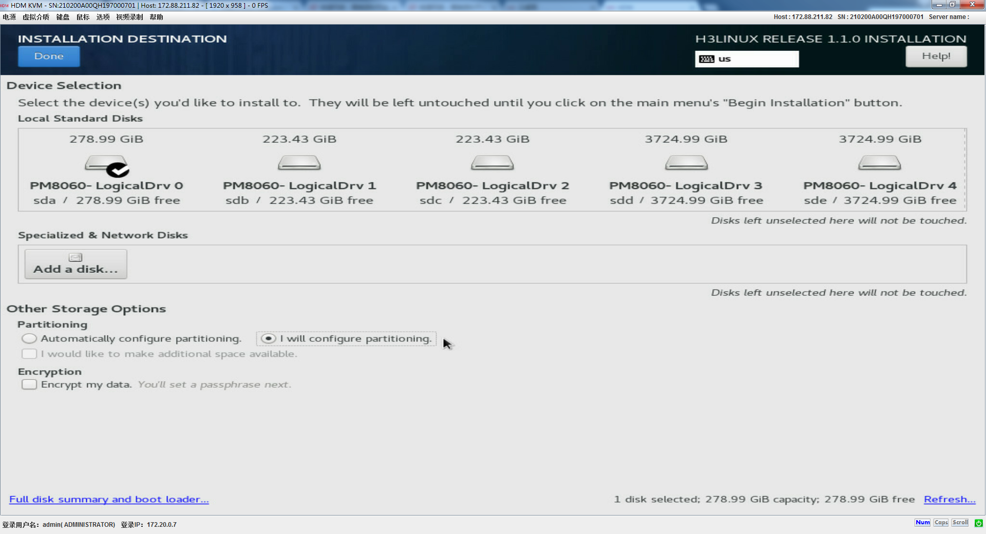
1. On the INSTALLATION SUMMARY page, select INSTALLATION DESTINATION.
Figure 14 INSTALLATION DESTINATION page
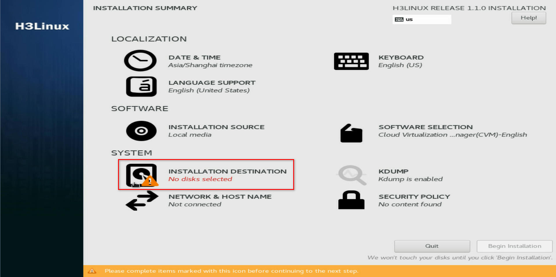
2. In the Local Standard Disks area, clear unrequired disks and leave one disk selected.
Figure 15 Selecting a system disk
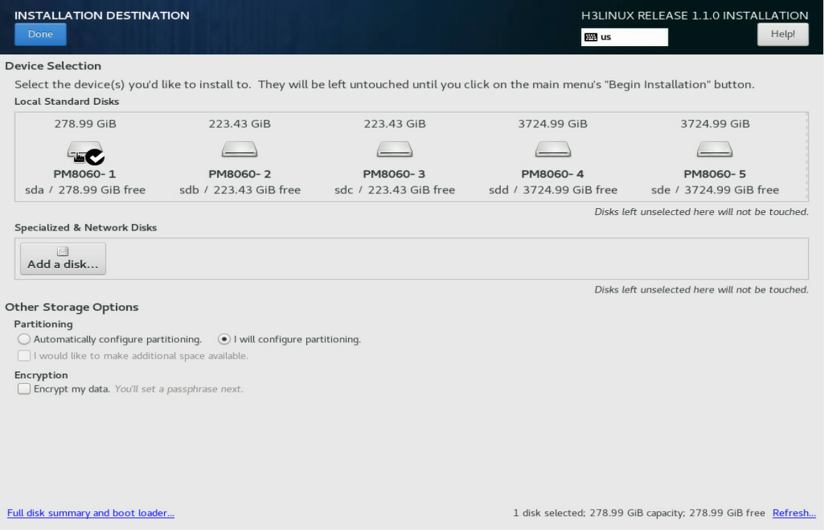
Partitioning the system disk
You can choose automatic or manual partitioning for the system disk. As a best practice, use automatic partitioning for the system disk if the system does not have special requirements for the partition sizes.
Automatic partitioning
1. On the INSTALLATION DESTINATION page, select Automatically configure partitioning in the Partitioning area.
Figure 16 Selecting automatic partitioning
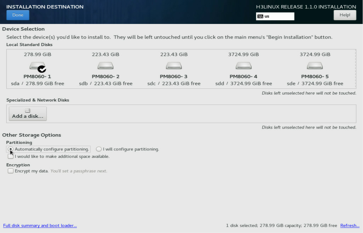
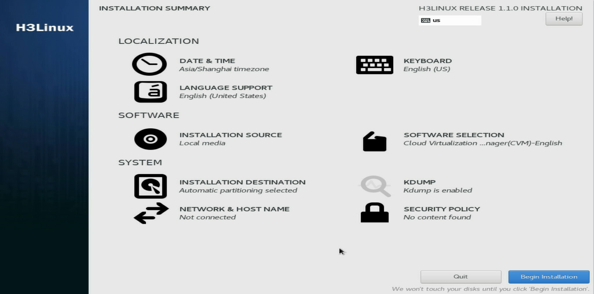
2. Click Done in the top left corner.
The system returns to the INSTALLATION SUMMARY page when the partitioning is complete.
Figure 17 INSTALLATION SUMMARY page
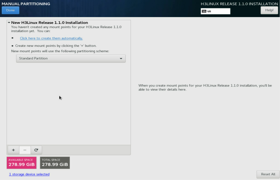
Manual partitioning
1. On the INSTALLATION DESTINATION page, select I will configure partitioning in the Partitioning area. Then click Done in the top left corner.
Figure 18 Selecting manual partitioning
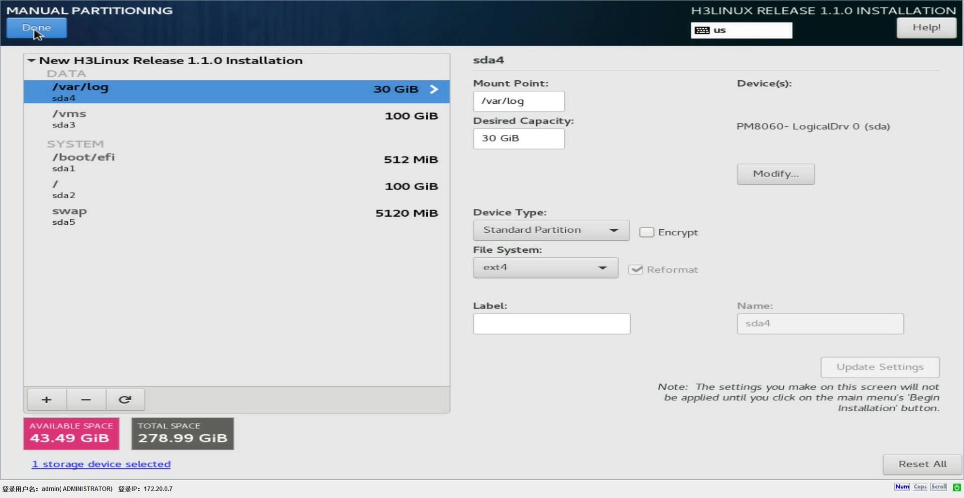
2. On the MANUAL PARTITIONING page, click the ![]() button.
button.
Figure 19 MANUAL PARTITIONING page
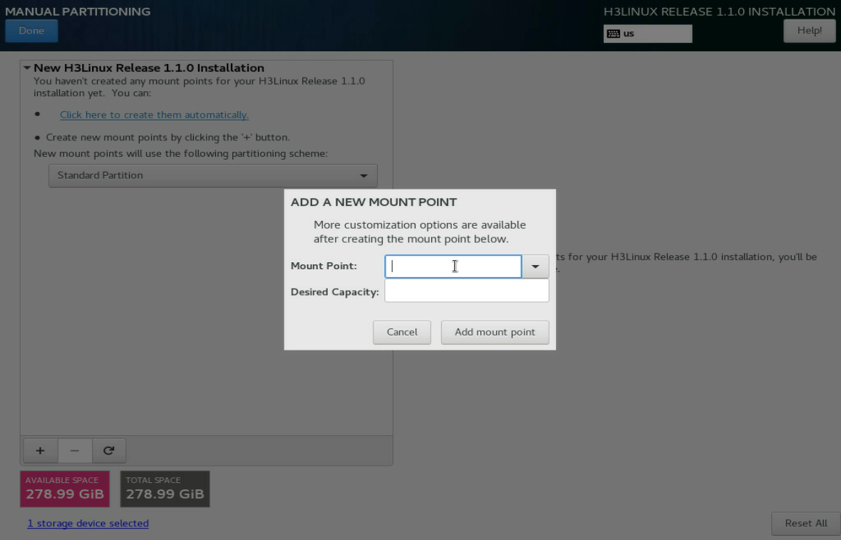
3. In the dialog box that opens, select a mount point and set a capacity for it. Then click Add mount point.
Figure 20 Adding a new mount point
4. Set the file system type for the partition and then click Update Settings.
Figure 21 Setting the file system type for the partition
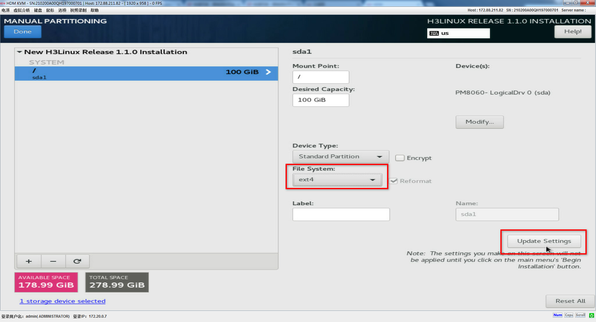
5. Perform the same steps to add the /, /boot/efi, swap, /vms, and /var/log partitions in sequence. See Table 20 for the descriptions and specifications for the partitions.
Table 20 Partition descriptions and specifications
|
Partition |
Description |
File system |
Recommended size |
Remarks |
|
/ (root partition) |
Stores all directories in the system. Users can access all directories from this partition. |
ext4 |
≥ 100 GiB (120 GiB) |
N/A |
|
/boot/efi (bootstrap partition) |
Stores boot files of the system. |
EFI System Partition |
≥ 512 MiB (512 MiB) |
This partition must be created if the server uses UEFI boot mode. This partition is not required if the server uses Legacy boot mode. |
|
swap (swap partition) |
Stores temporary data when the system memory is insufficient and transfers the temporary data into the memory for execution after a period of time. This partition is accessible only to the system. |
swap |
≥ 5 GiB (32 GiB) |
N/A |
|
/vms (VM data partition) |
Stores all data files of VMs. |
ext4 |
≥ 100 GiB (unallocated disk size) |
For example, specify a disk size of 117 GiB for the /vms partition for a disk of 300 GiB. |
|
/var/log (log partition) |
Stores log files about system operations. |
ext4 |
≥ 30 GiB (30 GiB) |
N/A |
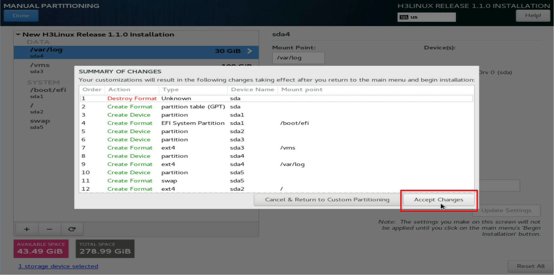
Figure 22 shows information about the partitions after the partitioning is complete.
Figure 22 Information about the partitions
6. Click Done in the top left corner.
7. In the dialog box that opens, click Accept Changes to confirm the partitioning. Then the system returns to the INSTALLATION SUMMARY page.
Figure 23 Confirming the partitioning
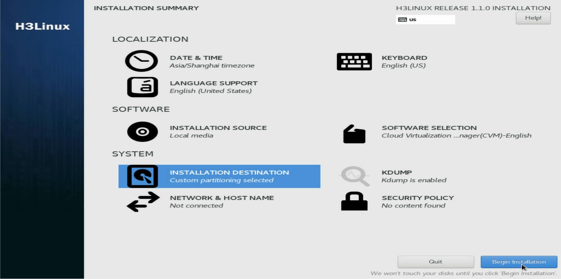
Starting installation
1. On the INSTALLATION SUMMARY page, click Begin installation.
Figure 24 Starting installation
The root password is automatically set to Sys@1234 during the installation process.
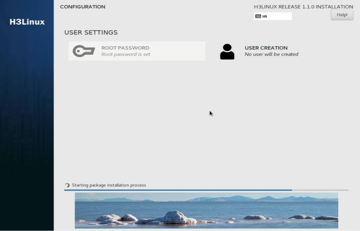
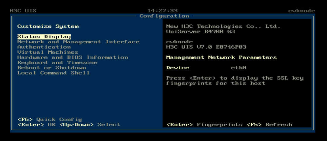
After the installation is complete, the host, cloud endpoint, or VM restarts automatically and opens the Configuration screen.
Figure 25 Host configuration screen
|
|
NOTE: · If a DHCP server exists in the management network, the server will obtain a management IP address from the DHCP server automatically after Space Console is installed. You must change the management IP address to a static one. · If no DHCP server exists in the management network, all management network parameters on the Configuration screen are empty. Set a static management IP address manually. |
Verifying the software versions
|
|
IMPORTANT: To avoid issues caused by incorrect software version, verify the version of the installed software after the installation is complete. |
Verifying the Workspace version
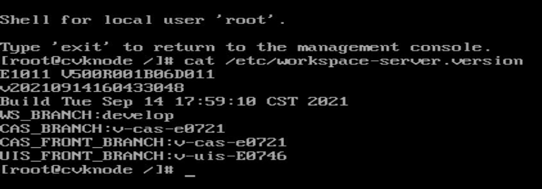
1. Access the Linux system.
The default username and password are root and Sys@1234, respectively.
2. Execute the cat /etc/workspace-server.version command to view Workspace version information. The version is E1011 in this example.
Figure 26 Workspace version information
Verifying the kernel version
Access the Linux system and then execute the uname –a command to verify the system kernel version.
Figure 27 Verifying the system kernel version
![]()
Verifying installation of Workspace components
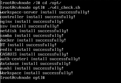
1. Access the Linux system.
2. Access the /opt directory.
3. Execute the ./vdi_check.sh command to verify installation of Workspace components.
Figure 28 Verifying installation of Workspace components
|
|
NOTE: If the manual installation version of the ISO image file is used for the installation and the host is a CVK node, some components such as workspace-server/database will not be installed successfully, which is normal and does not affect services. |
Configuring and accessing Space Console
Configuring a management IP address
After completing the installation of Space Console on all servers and the external monitor node, you must specify a CVM node as the management node and configure a static management IP address for each node.
|
|
IMPORTANT: After installation of Space Console on a server, you must set a management IP address for the server manually. |
To configure a static management IP address:
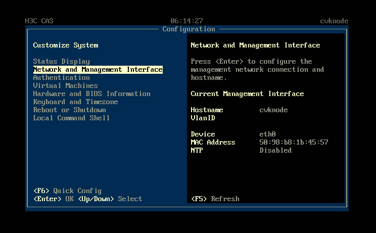
1. Open the KVM console of the server and then access the configuration screen.
2. Select Network and Management Interface and then press Enter.
Figure 29 Selecting Network and Management Interface
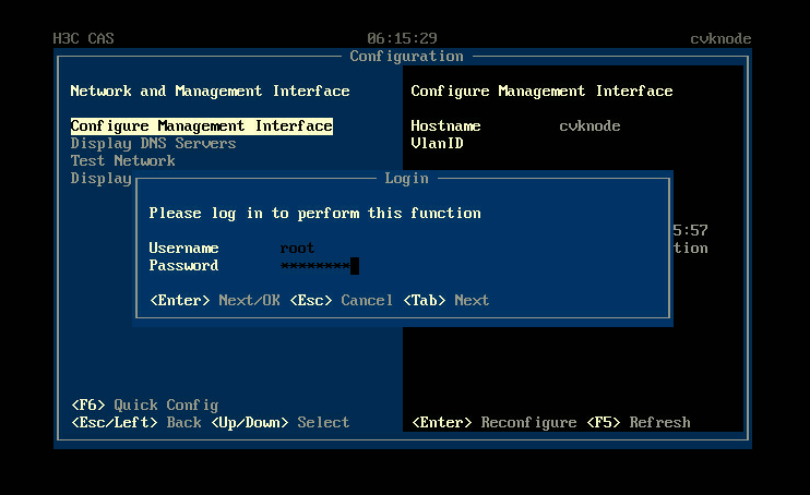
3. Select Configure Management Interface and then press Enter. In the dialog box that opens, enter the root password, and then press Enter.
The default root password is Sys@1234.
Figure 30 Selecting Configure Management Interface
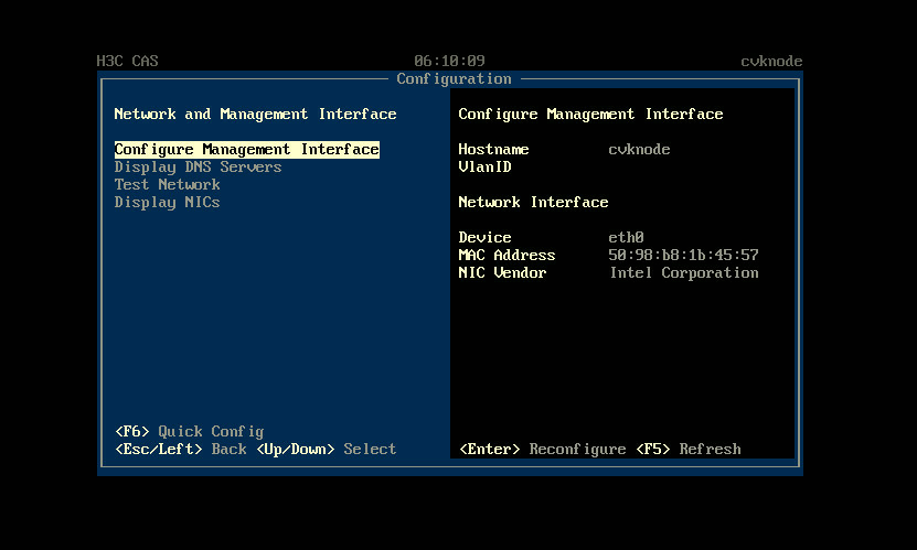
Figure 31 Login dialog box
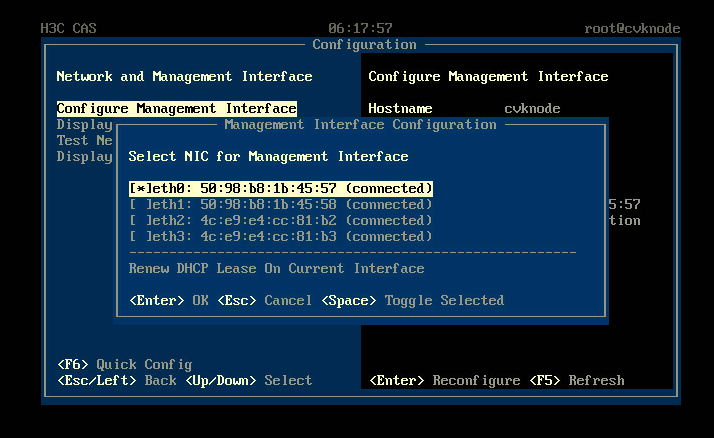
4. Select a management network interface and then press Enter.
Figure 32 Selecting a NIC
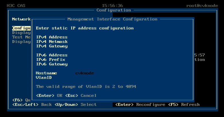
5. Enter the IP address, subnet mask, gateway address, hostname, and VLAN ID for the management interface as needed, and then press Enter.
|
|
CAUTION: You cannot configure an IP address on 172.17.0.0/16 and its subnets as the IP address of the management interface. By default, IP addresses on 172.17.0.0/16 and its subnets have been assigned to existing services in the system. |
Figure 33 Configuring management interface parameters
Accessing the system
The Workspace self-service system is installed automatically when Space Console is installed. After the installation is complete, you can access the Workspace self-service system or Space Console from a Web browser. As a best practice, use Chrome 45+, Firefox 49+, or a later version.
Before accessing the Workspace self-service system or Space Console from a Web browser, configure the following settings for the browser.
· Disable pop-up blocker.
· Allow cookies.
· Add the H3C Space Console site to the trusted sites.
· Make sure the monitor has a minimum width resolution of 1280 pixels. As a best practice, use a monitor that has a resolution of 1440*900 or higher.
|
|
NOTE: Refresh the browser if some webpages are garbled. Garbled webpages might be caused by incomplete loading of resources. |
Accessing the Workspace self-service system (office scenario)
The access method differs depending on whether gateway proxy is enabled. For information about enabling gateway proxy for the Workspace self-service system, see H3C Workspace Cloud Desktop Security Gateway Installation and Deployment Guide (Office Scenario).
With gateway proxy disabled
1. Launch your Web browser. Enter http://Management IP address:8083/ssv/#/login in the address bar. The Workspace self-service system login page is displayed.
The management IP address is the one that you configured in "Configuring a management IP address."
Figure 34 Workspace self-service system login page (with gateway proxy disabled)
2. For a non-admin user, click the Registration link to register a user account. For an admin user, use the default administrator account and password for login.
The default administrator account and password are admin and Cloud@1234, respectively.
With gateway proxy enabled
With gateway proxy enabled, a non-admin user can access the Workspace self-service system from an external network through the gateway proxy. An admin user is required to access the self-service system from the internal network.
· Non-admin user
a. Launch a Web browser.
b. Enter http://Gateway IP address:8083/ssv/#/login in the address bar.
c. Click the Registration link to register a user account.
Figure 35 Workspace self-service system login page (with gateway proxy enabled)
· Admin user
a. Launch a Web browser from the internal network.
b. Enter http://Management IP address:8083/ssv/#/login in the address bar.
The management IP address is the one that you configured in "Configuring a management IP address."
c. Enter the administrator account and password.
The default administrator account and password are admin and Cloud@1234, respectively.
Accessing Space Console
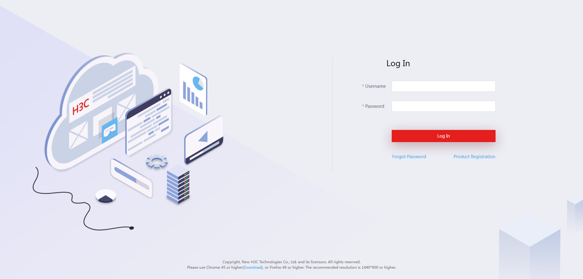
1. Launch a Web browser, and then enter http://Management IP address in the address bar. The Space Console login page is displayed.
Figure 36 Space Console login page
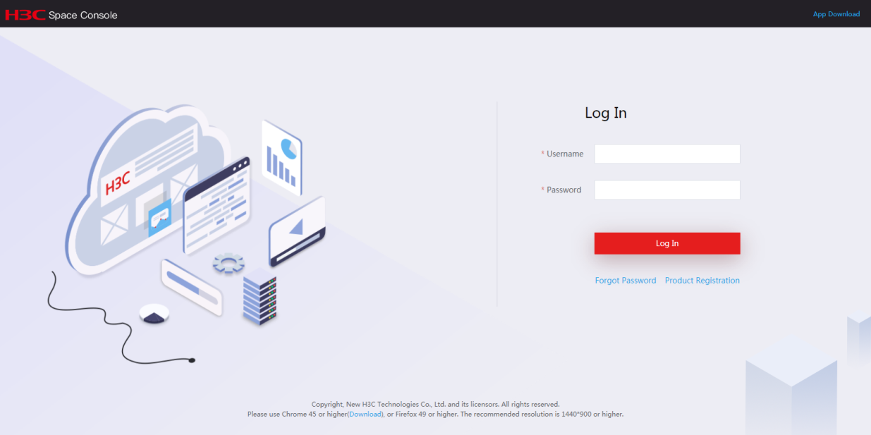
2. Enter the administrator account and password, and then click Login.
The default administrator account and password are admin and Cloud@1234, respectively.
Initializing Space Console
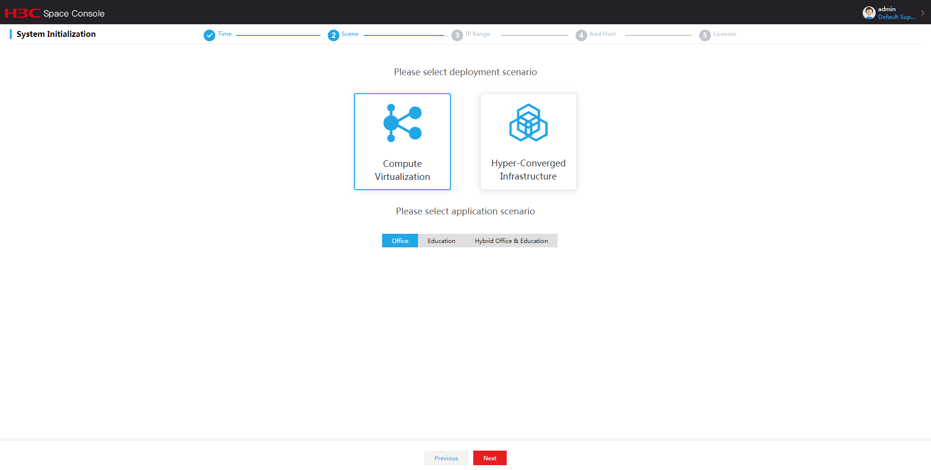
At the first login to Space Console, you are required to initialize the system. The system supports two deployment modes: compute virtualization and HCI.
|
|
IMPORTANT: · You can only deploy compute virtualization on a host in the education scenario. · Before initializing the system, execute the uname –a command in the Linux system on each server to verify that the servers are consistent in kernel versions. If the servers are inconsistent in kernel versions, the initialization might fail. For the method of checking the host kernel, see "Verifying the kernel version." |
Deploying the system in compute virtualization mode
1. On the login page, enter the default username and password, and then click Log In.
The default username and password are admin and Cloud@1234, respectively.
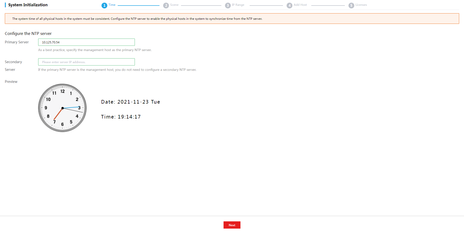
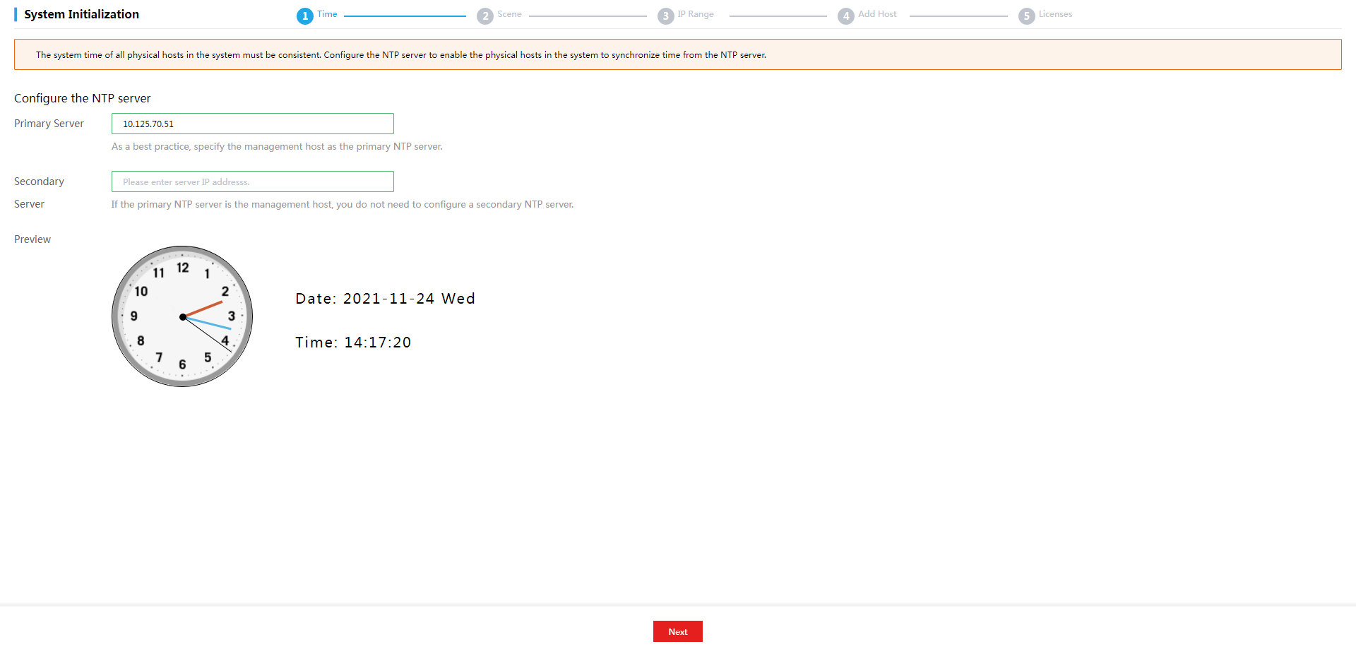
2. Specify the primary and secondary NTP servers, and then click Next.
Figure 37 Specifying the primary and secondary NTP servers
|
|
NOTE: · As a best practice, configure the management server as the primary NTP server. You are not required to specify a secondary NTP server when the management server is configured as the primary NTP server. · As a best practice, set the system time of the NTP server to be consistent with the time zone to which the NTP server belongs. · Do not edit the configuration after you finish configuring the NTP server. |
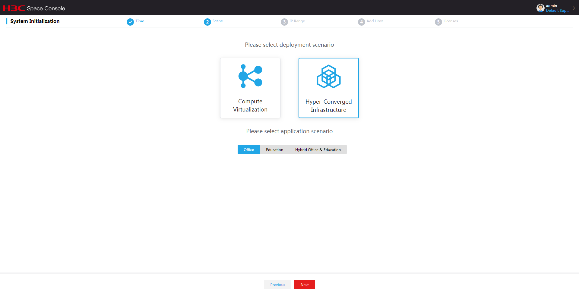
3. Select the compute virtualization deployment scenario and office, education, or hybrid office & education application scenario as needed. Then click Next.
For the services provided in each scenario, see H3C Workspace Desktop Management software User Manual.
Figure 38 Selecting scenarios
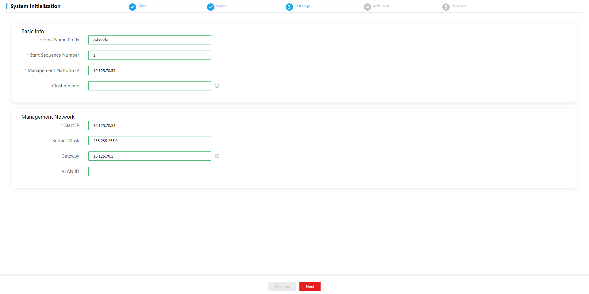
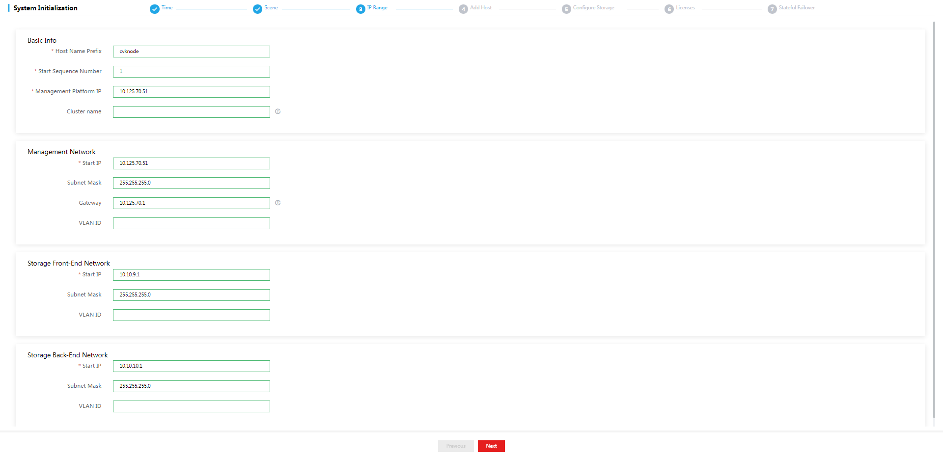
4. Configure network parameters, and then click Next.
Figure 39 Configuring network parameters
|
|
IMPORTANT: · You are not allowed to configure an IP address on 172.17.0.0/16 and its subnets as the management IP address. IP addresses on 172.17.0.0/16 and its subnets have been used by existing services in the system by default. · Make sure the starting IP, subnet mask, gateway, and VLAN ID of the management network are configured correctly. If they are not configured or configured incorrectly, the initialization might fail. · The default cluster name cluster_0 will be used if you do not specify a cluster name. |
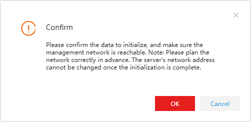
5. In the dialog box that opens, click OK.
Figure 40 Confirmation dialog box
|
|
NOTE: After the network parameters are deployed, the management IP address will be changed to the start IP address of the management network. · If the start IP address of the management network is different from the management IP used for login, the system refreshes the page and opens the login page with the start IP address. You must enter the username and password to enter the Host Settings page. · If the start IP address of the management network is the same as the management IP used for login, the system enters the Host Settings page directly. |
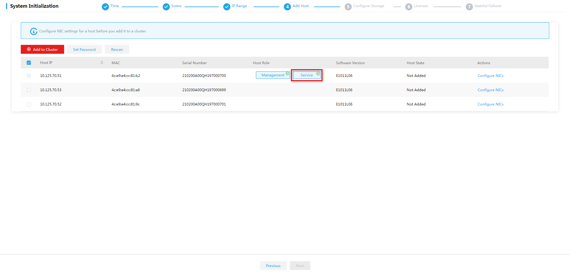
6. Select hosts for the cluster.
Figure 41 Selecting hosts for the cluster
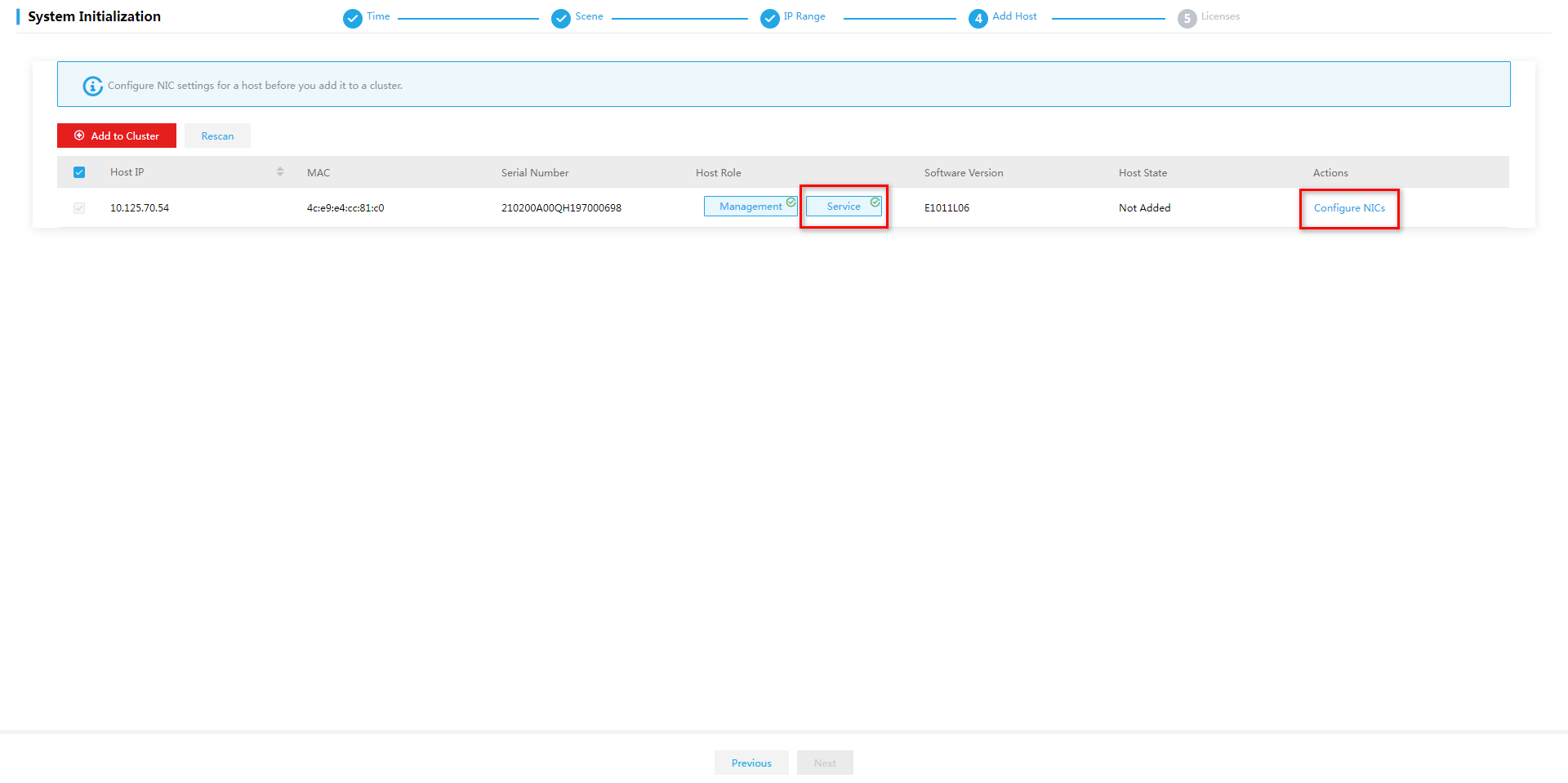
This figure shows the configuration for the converged deployment mode. For separate deployment mode, deselect the Service node type for the management host. For recommended management server configurations for the separate deployment mode, see "Hardware requirements for a management server that can operate only as a management node."
7. Click Configure NICs for each host in sequence and configure the parameters as needed.
Figure 42 Configuring NIC
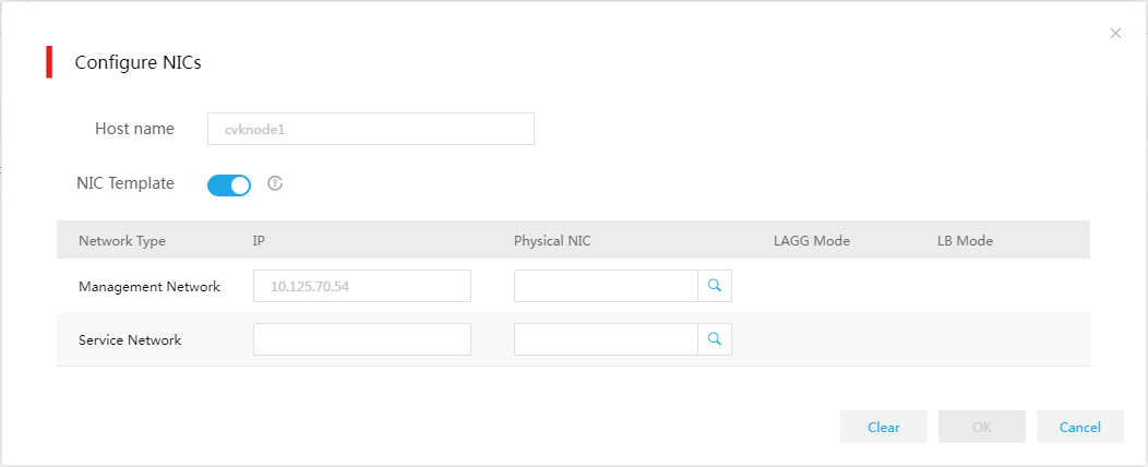
Table 34 Parameter description
|
Item |
Description |
|
NIC Template |
Select whether to apply physical interface settings on the host to other hosts in the cluster. For this feature to take effect, make sure the other hosts have active physical interfaces of the same names as those on this host and the interface speeds are as required. If a host does not meet the requirements, you must configure physical interface settings for the host manually. |
|
IP Address |
Specify a management IP address for the service node. If you do not specify a management IP address, the system assigns an available IP next to the start IP with an increment of 1 to the host. You do not need to specify a service network IP for a host. |
|
Physical Interfaces |
You must specify a physical interface for the management network. The physical interface for the service network can be specified as needed. For the management network, this field is required. For the service network, this field is optional. If you do not specify the interface, the system does not create a virtual switch for the service network after deployment, and you must create the switch from Space Console manually. |
|
|
IMPORTANT: To avoid configuration lost, make sure the interface sharing settings (except for interface numbers) for all the hosts are the same. For example, in a two-host cluster, the management and service networks for host A use physical interfaces eth0 and eth1, respectively. Whether the interface settings for host A can take effect depends on settings for host B. · If you configure the management and service networks for host B to share one physical interface eth0, the physical interface settings for host A become invalid. · If you configure the management and service networks for host B to use physical interfaces eth2 and eth3, respectively, the physical interface settings for host A are still valid. |
8. Specify the physical NICs for the management network and service network in sequence.
a. Click the ![]() icon for the
network.
icon for the
network.
b. Configure physical interface parameters and specify physical interfaces.
c. Click OK.
The link aggregation mode at the switch side depends on the configured LAGG mode and LB mode. Use Table 36 to determine the link aggregation mode at the switch side.
Figure 43 Selecting physical interfaces
Table 35 Parameter description
|
Item |
Description |
|
LAGG Mode |
Select the link aggregation mode for physical NICs. Options include Static Link Aggregation and Dynamic Link Aggregation. By default, static link aggregation is used. As a best practice, specify the Dynamic Link Aggregation mode. The physical switch must be enabled with LACP if the dynamic LAGG mode is used. This parameter can be configured only when multiple physical interfaces are configured. |
|
LB Mode |
Select the load balancing mode for physical NICs. Options include Advanced LB, Basic LB, and Active/Standby LB. This parameter can be configured only when multiple physical interfaces are configured for the management network. · Advanced—Load balances traffic between physical NICs based on the Ethernet type, IP protocol, source IP address, destination IP address, application layer source port number, and application layer destination port number of packets. · Basic—Load balances traffic between physical NICs based on the source MAC address and VLAN tag of packets. · Active/Standby—Load balances traffic between the active and standby physical NICs. When the active physical NIC fails, the system switches to the standby physical NIC for traffic forwarding. This option can be selected only when the static LAGG mode is specified. As a best practice, use the basic LB mode. |
Table 36 Required link aggregation mode at the switch side
|
Host LAGG mode |
Host LB mode |
Switch link aggregation mode |
|
Static |
Active/standby |
Not configured |
|
Static |
Basic |
Static |
|
Static |
Advanced |
Static |
|
Dynamic |
Basic |
Dynamic |
|
Dynamic |
Advanced |
Dynamic |
|
|
IMPORTANT: If VLAN settings are configured for the logical networks, configure the physical switch ports as trunk ports and assign the ports to the corresponding VLAN. |
|
|
IMPORTANT: Follow these restrictions and guidelines when configuring the link aggregation mode for the port that connects a physical switch to a physical interface on a host: · Do not configure link aggregation on the port if the LAGG mode is Static and the LB mode is Active/Standby on the host. · Configure static link aggregation on the port if the LAGG mode is Static and the LB mode is Advanced or Basic on the host. If Space Console cannot detect the host after the configuration, shut down all the physical switch ports connecting to the host's management network ports that are not bound to vswitch0. Then, try to detect the host again. · Configure dynamic link aggregation on the port if the LAGG mode is Dynamic. If Space Console cannot detect the host after the configuration, specify the physical switch ports that connecting to the host's management network ports as edge aggregate interfaces. Then, try to detect the host again. |
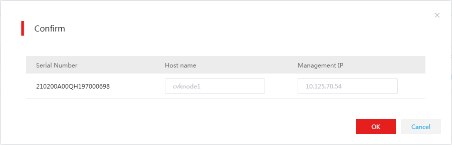
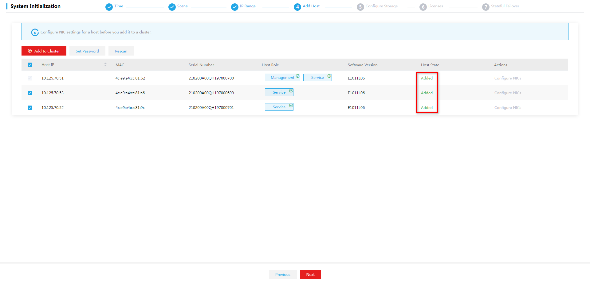
9. Select the hosts and then click Add to Cluster to add the hosts to the cluster. Then click OK in the dialog box that opens.
Figure 44 Adding hosts to the cluster
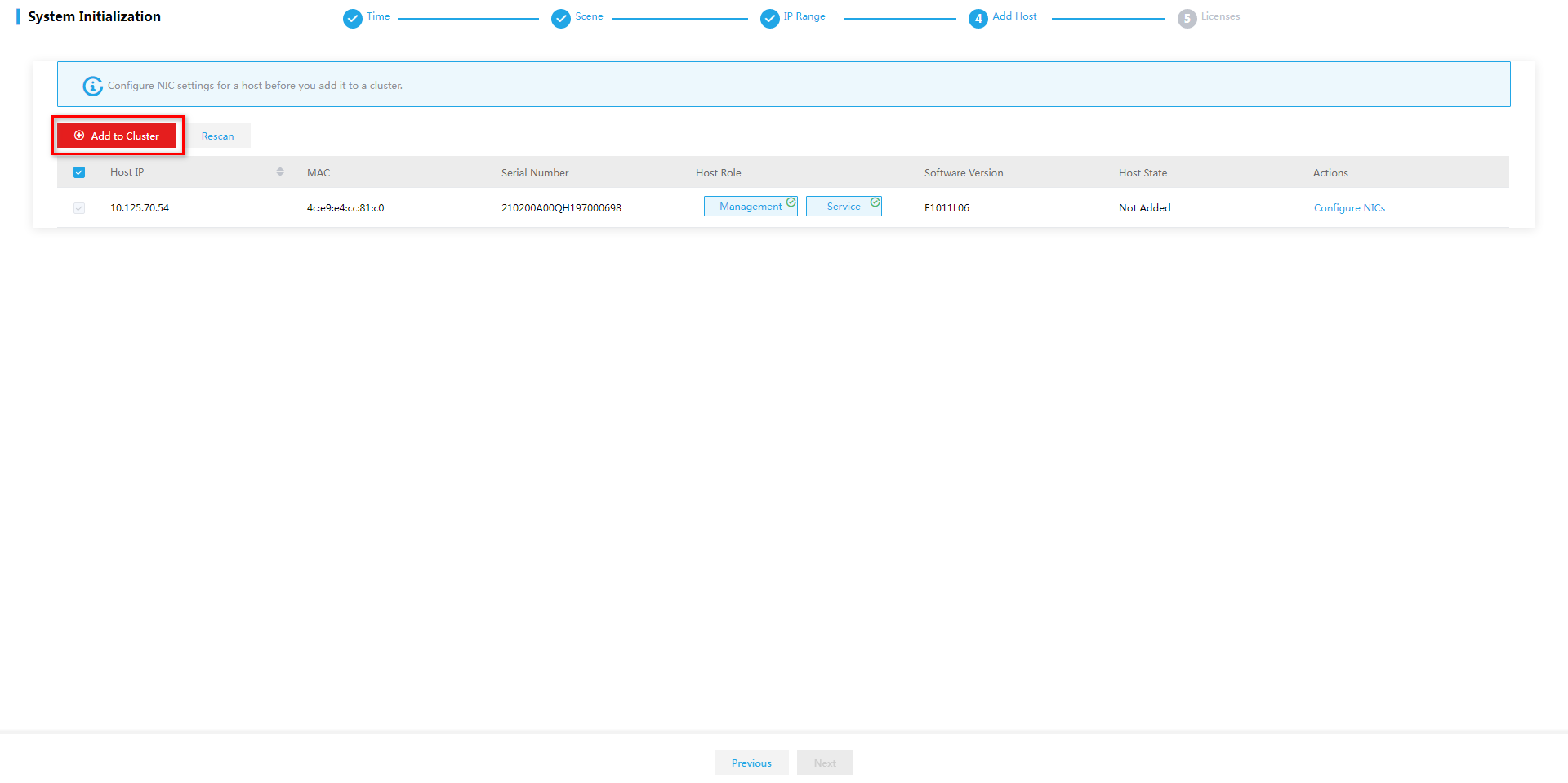
Figure 45 Confirmation dialog box
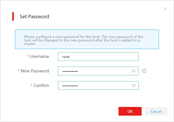
10. Set the root password for each host, and then click OK.
Figure 46 Setting the root password
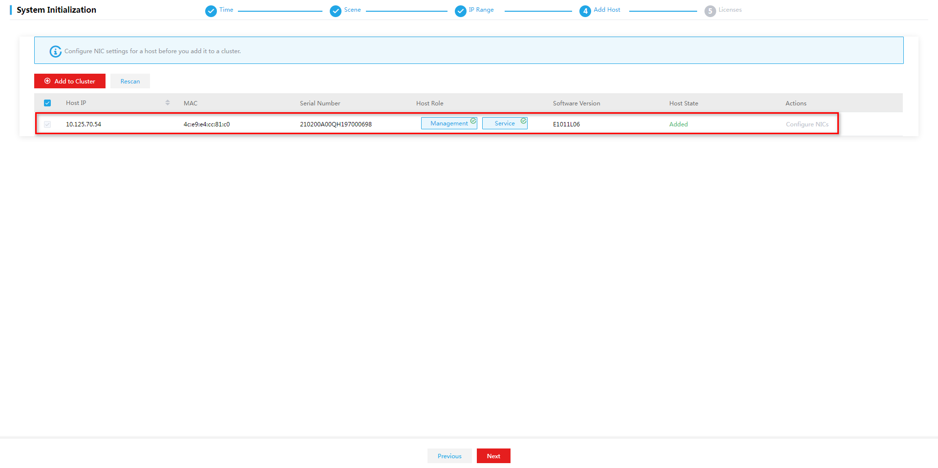
11. The system starts to add the host to the cluster and then returns to the Host Settings page after the configuration. Verify that the Host State field of the hosts added to the cluster has been changed to Added.
Figure 47 Host Settings page
12. Click Next.
|
|
CAUTION: Before clicking Next to go to the next step, make sure the host configuration is correct. Once you click Next, you are not allowed to return to the previous configuration. |
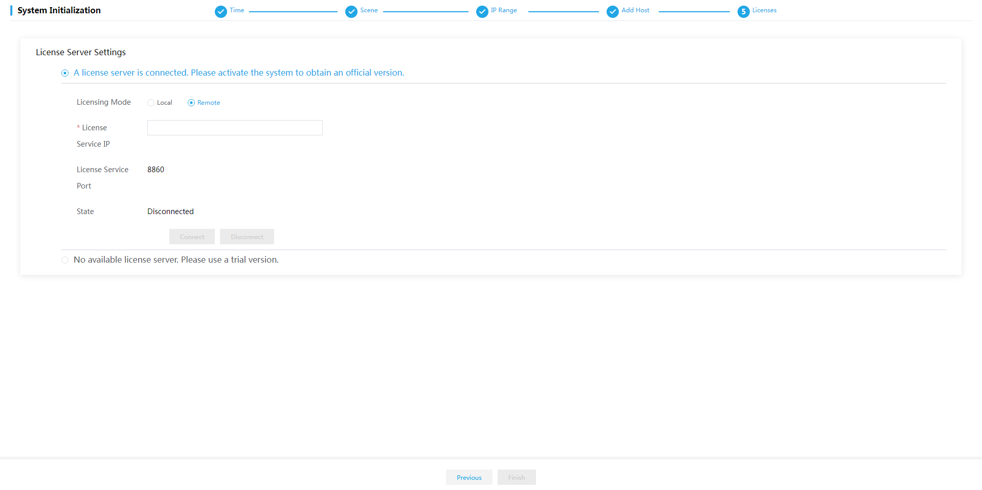
13. On the Licenses page, perform either of the following tasks:
¡ If you have completed license application, select A license server is connected. Please activate the system to obtain an official version and then configure the following settings:
# Select the licensing mode. Options include Local and Remote.
# Enter the license server IP address and port number and client name and password.
# Click Connect to connect to the license server. After the connection to the license server is established, Space Control will obtain licensing information automatically.
|
|
IMPORTANT: · Local licensing is managed by the license server connected to Space Console. Use a license server of E1145 or later when Space Console is E1003 or later. · Remote licensing is managed by CloudOS. Select remote licensing when Space Console is managed by the cloud operating system. |
¡ If no licenses have been applied for, select No available license server. Please use a trial version, and then click Finish.
Figure 48 Local licensing configuration
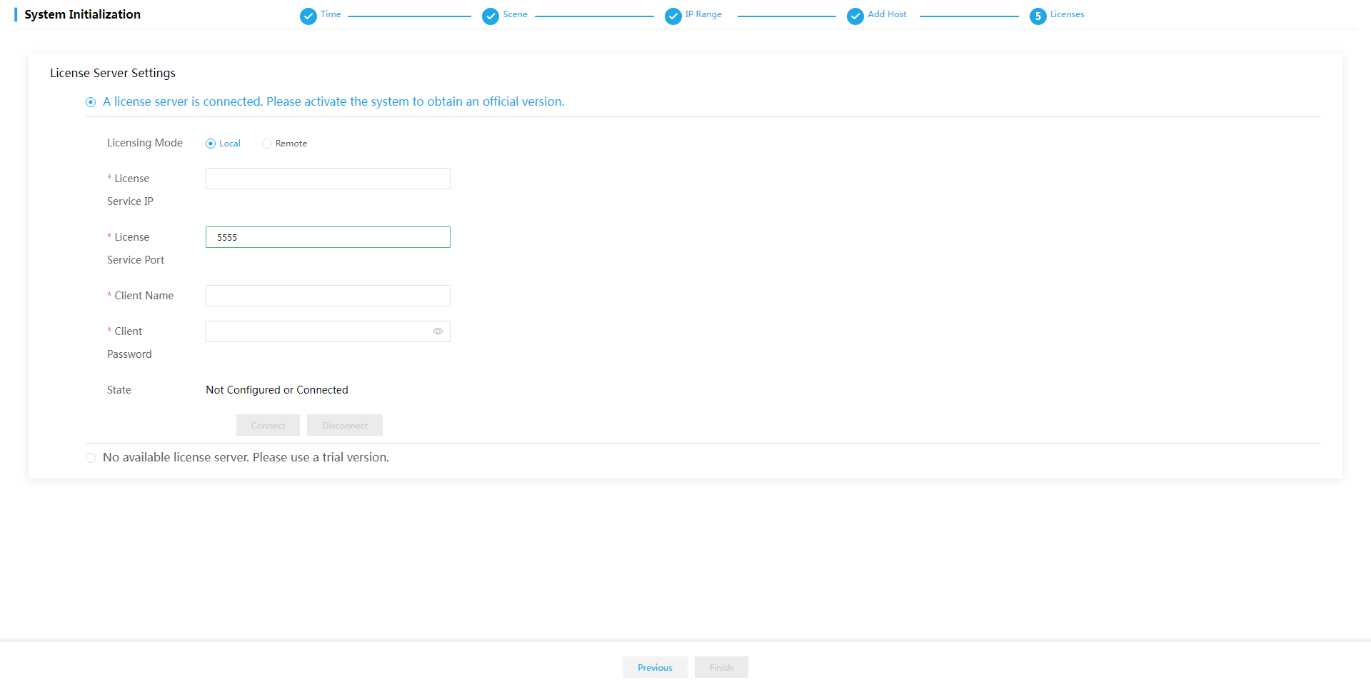
Figure 49 Remote licensing configuration
After the licenses are activated, the system automatically enters the Dashboard page.
Figure 50 Dashboard (office scenario)
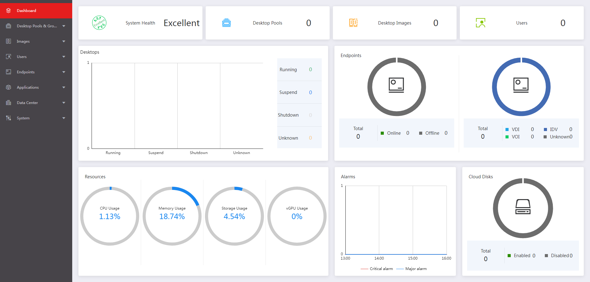
Figure 51 Dashboard (education scenario)
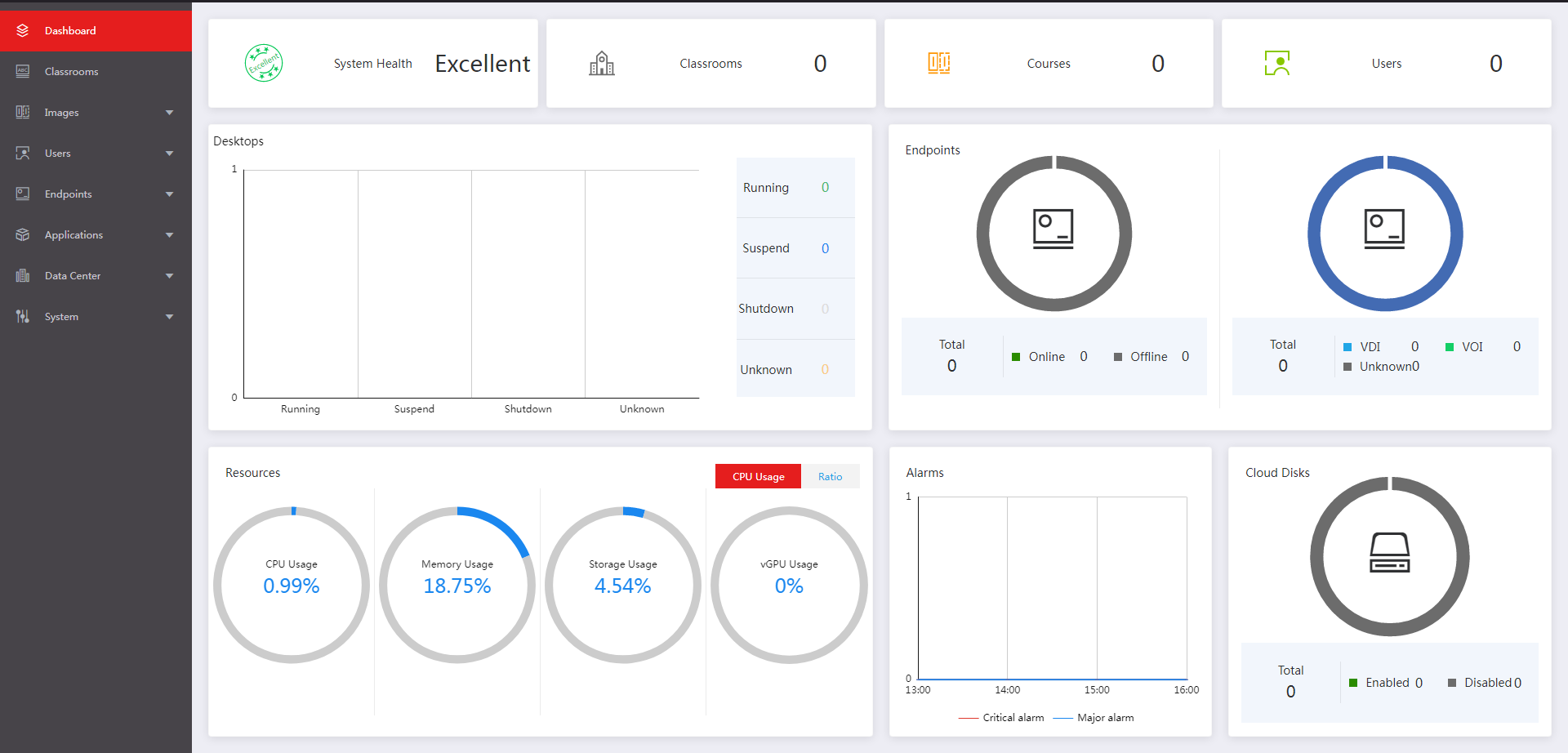
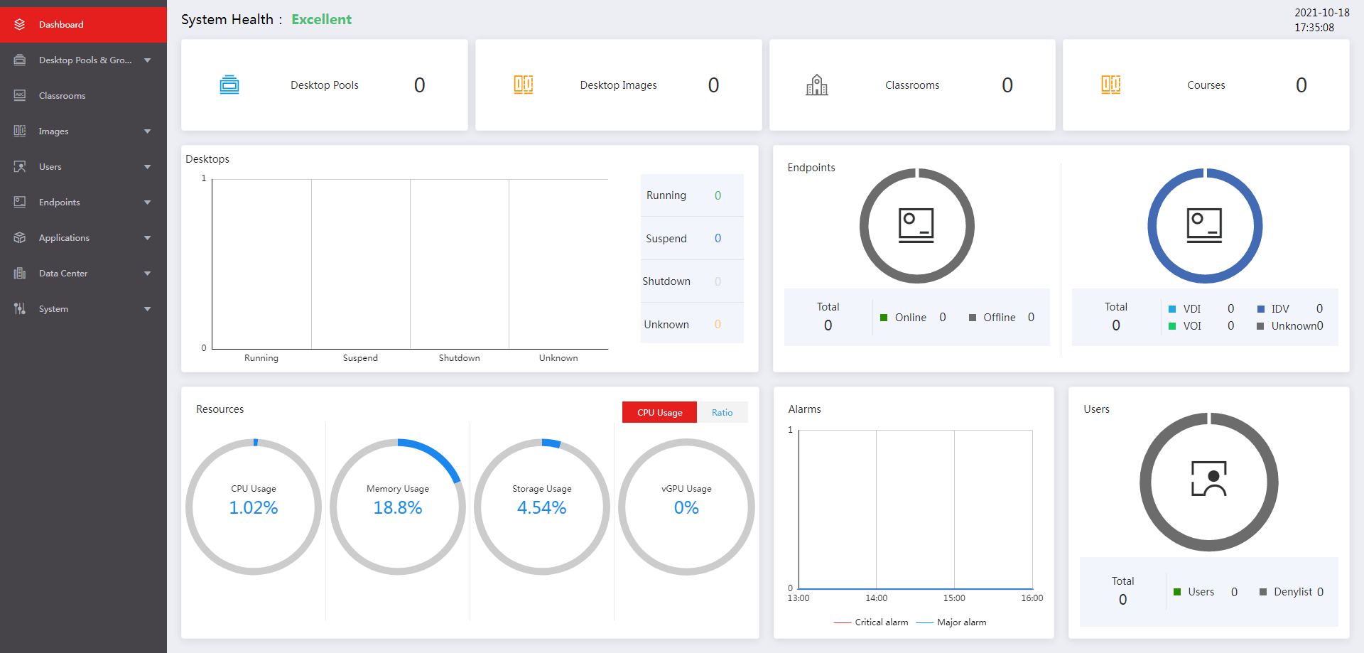
Figure 52 Dashboard (hybrid office & education scenario)
Deploying the system in HCI mode
Three or more hosts
1. On the login page, enter the default username and password, and then click Log In.
The default username and password are admin and Cloud@1234, respectively.
Figure 53 Space Console login page
2. Specify the primary and secondary NTP servers, and then click Next.
Figure 54 Specifying the primary and secondary NTP servers
|
|
NOTE: · As a best practice, specify the management server as the primary NTP server. You are not required to specify a secondary NTP server when the management server is configured as the primary NTP server. · As a best practice, set the system time of the NTP server to be consistent with the time zone to which the NTP server belongs. · Do not edit the configuration after you finish configuring the NTP server. |
3. Select the Hyper-Converged Infrastructure deployment scenario and then select the Office or Hybrid Office & Education application scenario as needed. Then click Next.
The education scenario does not support HCI deployment.
For the different services provided in each scenario, see H3C Workspace Desktop Management Software User Manual.
|
|
CAUTION: In the hybrid office and education scenario, to use the features available in the education scenario, first create a compute virtualization cluster on Space Console. For how to create a compute virtualization cluster, see Data center-Virtualization-Configure clusters in H3C Workspace Desktop Management Software User Manual. |
Figure 55 Selecting scenarios
4. Configure network parameters, and then click Next.
Figure 56 Configuring network parameters
|
|
IMPORTANT: · You cannot configure an IP address on 172.17.0.0/16 and its subnets as the management IP address. IP addresses on 172.17.0.0/16 and its subnets have been used by existing services in the system by default. · Make sure the starting IP, subnet mask, gateway, and VLAN ID of the management network are configured correctly. If they are not configured or configured incorrectly, the initial deployment might fail. · The default cluster name cluster_0 will be used if you do not specify a cluster name. |
5. In the dialog box that opens, click OK.
Figure 57 Confirmation dialog box

|
|
NOTE: After the network parameters are deployed, the management IP address will be changed to the start IP address of the management network. · If the start IP address of the management network is different from the management IP used for login, the system refreshes the page and opens the login page with the start IP address. You must enter the username and password to enter the Host Settings page. · If the start IP address of the management network is the same as the management IP used for login, the system enters the Host Settings page directly. |
6. Select hosts for the cluster.
Figure 58 Selecting hosts for the cluster
This figure shows the configuration for the converged deployment mode. For separate deployment mode, clear the Service node type for the management host. For recommended management server configurations for the separate deployment mode, see "Hardware requirements for a management server that can operate only as a management node."
7. Click Configure NICs for each host in sequence and configure the parameters as needed.
Figure 59 Configuring NICs
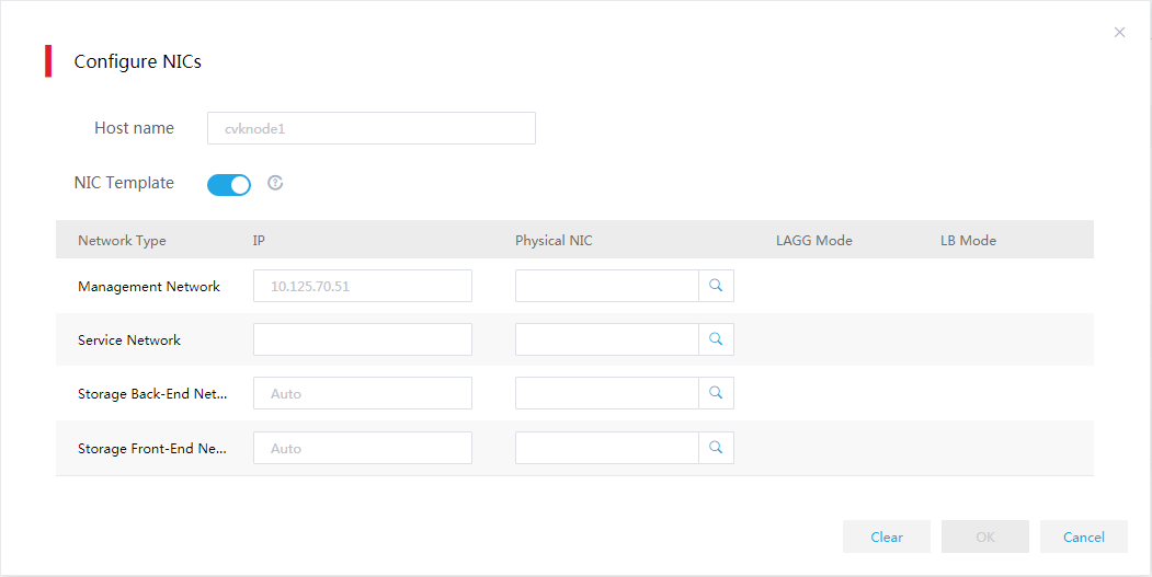
Table 37 Parameter description
|
Item |
Description |
|
NIC Template |
Select whether to apply physical interface settings of the host to other hosts. For this feature to take effect, make sure the other hosts have active physical interfaces of the same names as those on this host and the interface speeds are as required. If a host cannot meet the requirements, you must configure physical interface settings for the host manually. |
|
IP Address |
Specify a management IP address for service nodes. If you do not specify a management IP address, the system assigns an available IP next to the start IP with an increment of 1 to the host. You do not need to specify a service network IP for a host. |
|
Physical Interfaces |
You must specify physical interfaces for the management network, storage front-end network, and storage back-end network. The physical interface of the service network can be specified as needed. For the service network, this field is optional. If you do not specify the interface for the service network, the system does not create a virtual switch for the service network after deployment, and you must create the virtual switch on Space Console manually. |
|
|
IMPORTANT: To avoid configuration lost, make sure the interface sharing settings (except for interface numbers) for all the hosts are the same. For example, in a two-host cluster, the management and service networks for host A use physical interfaces eth0 and eth1, respectively, and the storage front-end and back-end networks share physical interfaces eth2 and eth3. Whether the interface settings for host A can take effect depends on settings for host B. · If you configure the storage front-end and back-end networks for host B to share interfaces eth1 and eth2, and the management and service networks to share interface eth0, the physical interface settings for host A become invalid. · If you configure the management and service networks for host B to use interfaces eth0 and eth1, respectively, and the storage front-end and back-end networks to share interfaces eth3 and eth4, the physical interface settings for host A are still valid. |
8. Click the ![]() icon
for the management network, service network (optional), storage back-end
network, and storage front-end network in sequence to specify physical
interfaces for them.
icon
for the management network, service network (optional), storage back-end
network, and storage front-end network in sequence to specify physical
interfaces for them.
9. Configure physical interface parameters as needed and then click OK.
The link aggregation mode at the switch side depends on the configured LAGG mode and LB mode. Use Table 39 to determine the link aggregation mode at the switch side.
Figure 60 Specifying physical interfaces

Table 38 Parameter description
|
Item |
Parameters |
|
LAGG Mode |
Select the aggregation mode of physical NICs. Options include Static Link Aggregation and Dynamic Link Aggregation. The physical switch must be enabled with LACP if the dynamic LAGG mode is used. This parameter is displayed only when multiple physical interfaces are configured. |
|
LB Mode |
Select the load balancing mode of physical NICs. Options include Advanced LB, Basic LB, and Active/Standby LB. This parameter is displayed only when multiple physical interfaces are configured for the management network. · Advanced LB—Load balances physical NICs based on the Ethernet type, IP protocol, source IP address, destination IP address, application layer source port number, and application layer destination port number of packets. · Basic LB—Load balances physical NICs based on the source MAC address and VLAN tag of packets. · Active/Standby LB—Load balances the active and standby physical NICs. When the active physical NIC fails, the system switches to the standby physical NIC for traffic forwarding. This option is displayed only when the static LAGG mode is used. As a best practice, use the basic LB mode. |
Table 39 Required link aggregation mode at the switch side
|
Host LAGG mode |
Host LB mode |
Switch link aggregation mode |
|
Static |
Active/standby |
Not configured |
|
Static |
Basic |
Static |
|
Static |
Advanced |
Static |
|
Dynamic |
Basic |
Dynamic |
|
Dynamic |
Advanced |
Dynamic |
|
|
IMPORTANT: If VLAN settings are configured for the logical networks, configure the physical switch ports as trunk ports and assign the ports to the corresponding VLAN. |
|
|
IMPORTANT: Follow these restrictions and guidelines when configuring the link aggregation mode for the port that connects a physical switch to a physical interface on a host: · Do not configure link aggregation on the port if the LAGG mode is Static and the LB mode is Active/Standby on the host. · Configure static link aggregation on the port if the LAGG mode is Static and the LB mode is Advanced or Basic on the host. If Space Console cannot detect the host after the configuration, shut down all the physical switch ports connecting to the host's management network ports that are not bound to vswitch0. Then, try to detect the host again. · Configure dynamic link aggregation on the port if the LAGG mode is Dynamic. If Space Console cannot detect the host after the configuration, specify the physical switch ports that connecting to the host's management network ports as edge aggregate interfaces. Then, try to detect the host again. |
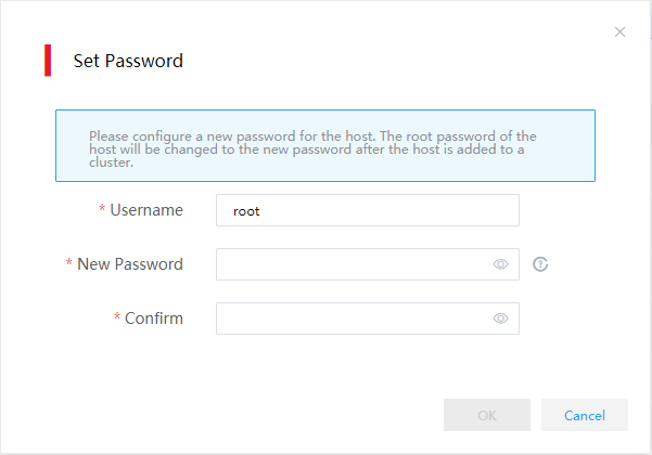
10. Click Set Password on the Host Settings page as shown in Figure 58.
11. Set the root password for all hosts and then click OK.
Figure 61 Setting the root password
12. Click Add to Cluster. In the dialog box that opens, verify the host name, management IP, storage front-end network IP, and storage back-end network IP settings for each host and then click OK to add the hosts to the cluster.
Figure 62 Verifying host settings
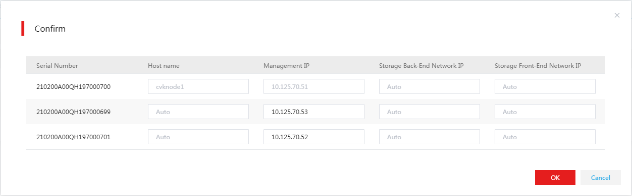
Figure 63 Host configuration in progress
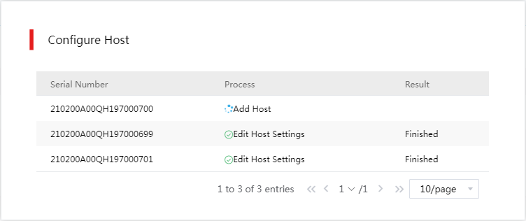
13. The system returns to the Host Settings page after adding the host to the cluster. Verify that the Host State field of the hosts added to the cluster has been changed to Added.
Figure 64 Host Settings page
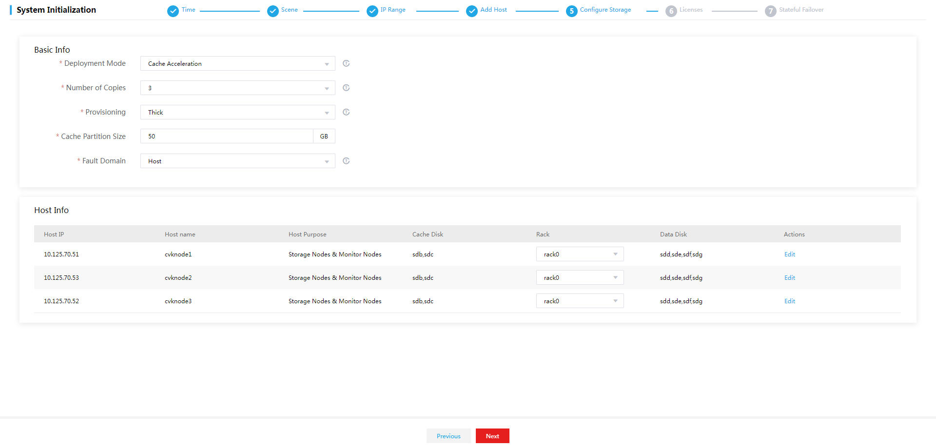
14. Configure storage deployment parameters as needed.
Figure 65 Configuring storage deployment parameters
|
|
IMPORTANT: During storage deployment, do not close the Space Console webpage from the browser or log out of Space Console. |
Table 40 Parameter description
|
Item |
Description |
|
Deployment Mode |
Select the storage cluster deployment mode. Options include Cache Acceleration, All SSDs, All HDDs, and HDDs+SSDs. · Cache Acceleration—Deploy HDDs as data disks to store data and deploy SSDs as cache disks to accelerate reads and writes. Make sure the ratio of SSDs and HDDs ≥ 1: 5. You can select System > Advanced Settings > Disk Pool Cache Acceleration Policy to configure cache acceleration for disk pools after the deployment only if you have selected the Cache Acceleration deployment mode. · All SSDs—Deploy SSDs as data disks to store data without using data caches. Use this mode to provide high-performance storage services. · All HDDs—Deploy HDDs as data disks to store data without using data caches. Use this mode to provide normal storage services. · HDDs+SSDs—Deploy SSDs and HDDs as data disks in high-performance storage pools and slow-performance storage pools, respectively, to provide storage services for applications that require different storage performance. |
|
Number of Copies |
Set the number of copies. As a best practice, configure three or more copies for crucial services or scenarios requiring high availability. |
|
Provisioning |
Select a block device provisioning mode. After Space Console completes initialization, the system creates a disk pool with the specified block device provisioning mode. This parameter determines how space is allocated to the block devices created in the data pool that uses the disk pool and whether resource overcommitment is allowed. · Thick—Allocates the specified maximum storage space to a block device when the block device is created. The capacity of a block device in a data pool cannot exceed the available capacity of the data pool. In this provisioning mode, the predefined storage pool will be configured as an iSCSI shared file system. · Thin—Allocates space to a block device on demand. The capacity assigned to a block device when it is created can exceed the available capacity of the data pool. In this provisioning mode, the predefined storage pool will be configured as an RBD network storage pool. |
|
Cache size |
Set the cache size. This parameter is available only when you select the Cache Acceleration deployment mode. The system divides SSDs into partitions and assigns a partition to each HDD data disk as its cache. By default, the cache size is 50 GB. Set a larger cache size for heavy data loads. |
|
Fault domain |
Select a fault domain level for the storage cluster. By using fault domains and a redundancy policy together, a storage cluster saves the replicas or fragments of data to different fault domains to ensure data security and high availability. The following fault domain levels are available: · Rack level—Each rack is a fault domain. The system preferentially distributes replicas or fragments of data across multiple racks. · Host level—Each host is a fault domain. The system preferentially distributes replicas or fragments of data across multiple hosts. |
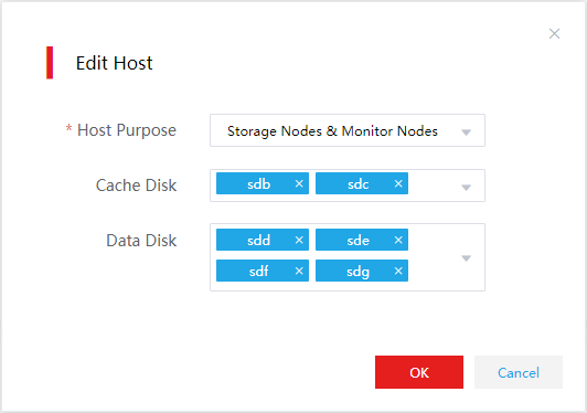
15. Select a rack for each host.
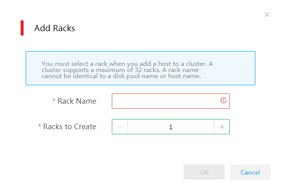
a. Select Configure Racks from the Rack list. In the dialog box that opens, click Add Racks.
b. Set the rack name and quantity and then click OK.
c. Select a rack and then click OK.
Figure 66 Configuring racks
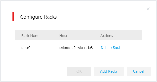
Figure 67 Adding racks
|
|
IMPORTANT: · A storage cluster can have a maximum of 32 racks. · A rack name cannot be identical to a disk pool name or host name. · As a best practice, create racks based on the actual rack mounting conditions of the hosts. For example, if six physical hosts are mounted on two racks, you can use the actual rack names to create two racks. |
16. Click the ![]() icon
in the Actions column for the host. In the dialog box that opens, edit the host
information. Then click OK.
icon
in the Actions column for the host. In the dialog box that opens, edit the host
information. Then click OK.
Figure 68 Editing host information
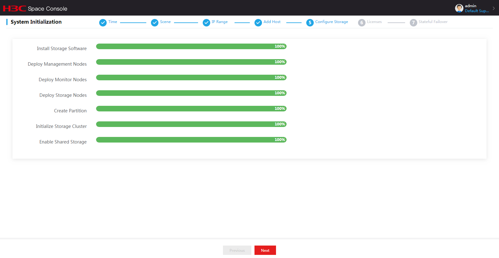
17. After storage configuration, click Next. In the dialog box that opens, click OK. The system starts deploying distributed storage automatically.
Figure 69 Confirmation dialog box
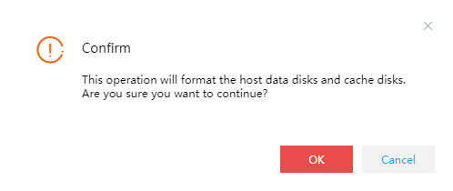
Figure 70 Automatic deployment of distributed storage
18. After distributed storage initialization is completed, click Next.
19. On the Licenses page, perform either of the following tasks:
¡ If you have completed license application, select A license server is connected. Please activate the system to obtain an official version and then configure the following settings:
# Select the licensing mode. Options include Local and Remote.
# Enter the license server IP address and port number and client name and password.
# Click Connect to connect to the license server. After the connection to the license server is established, Space Control will obtain licensing information automatically.
|
|
IMPORTANT: · Local licensing is managed by the license server connected to Space Console. Use a license server of E1145 or later when Space Console is E1003 or later. · Remote licensing is managed by CloudOS. Select remote licensing when Space Console is by the cloud operating system. |
¡ If no licenses have been applied for, select No available license server. Please use a trial version, and then click Finish.
Figure 71 Local licensing configuration
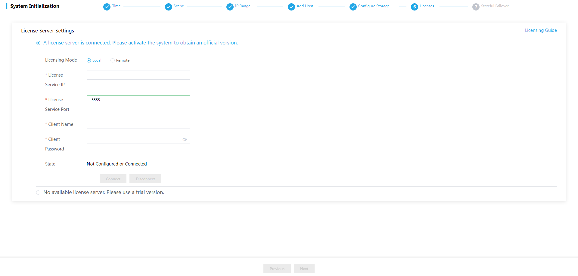
Figure 72 Remote licensing configuration
20. Set up a stateful failover system.
a. Click Set Up Stateful Failover System.
b. Configure the parameters as described in Table 41.
c. Click OK.
Figure 73 Stateful failover system setup page
Figure 74 Stateful failover system setup dialog box
Table 41 Parameter descriptions
|
Parameter |
Descriptions |
|
Virtual IP Address |
Specify the IP address for accessing Space Console. It must be an IP address not in use. |
|
Storage Component VIP |
Specify the virtual IP address used for high availability management of the distributed storage system. The virtual IP address can be automatically assigned or manually configured. It must be an unused IP address in the management network. |
|
Backup Host Location |
Specify the location of the backup Space Console. · Host in System—A host in a service cluster, such as a compute, network, or storage cluster. Select this option in a converged deployment environment. · Others—A host not in a service cluster. Select this option in a distributed deployment environment. |
|
Backup Host IP |
Specify the management IP address of the backup Space Console host. You are required to set this parameter if the location of the Space Console is Host in System.. |
|
Select Backup Host |
Select the backup host by its IP address. This parameter is available if the backup host is not in a service cluster. |
|
Backup Host IP |
IP address of the backup host. This parameter is automatically populated with the IP address of the selected backup host. This parameter is available if the backup host is not in a service cluster. |
|
Quorum Mode |
Select a quorum mode. Options include Advanced and Ping. · Advanced—When the primary and backup hosts cannot communicate with each other, they send their respective state information to the quorum host. The quorum host determines the role of each node and sends the role information to the nodes. The quorum host must have Space Console installed. As a best practice, use a host in the cluster as a quorum host. · Ping—When the primary and backup hosts cannot communicate with each other, they ping the quorum IP addresses. If a node fails to ping any quorum IP address, the node determines that it has network failures and becomes a backup node. |
|
Quorum Host IP |
Specify the IP address of the quorum host. |
|
Quorum Host Root PWD |
Enter the root password of the quorum host. |
|
Quorum IP Address |
Specify the IP address of a gateway that can be accessed or the IP address of a host that is always reachable. The quorum IP address is used to check the network connectivity of the hosts. As a best practice, specify the IP address of a gateway. You must specify two different quorum IP addresses if you select the Ping quorum mode. |
|
Estimated Host Quantity |
Enter the estimated number of hosts in Space Console for calculating the database partition size. |
|
Estimated VM Quantity |
Enter the estimated number of VMs in Space Console for calculating the database partition size. |
|
Database Partition Size |
Specify the database partition size. The database partition is used for data synchronization between the primary and backup hosts and is part of the /vms partition. Database partition size (in MB) = (Estimated host quantity × 7 MB + estimated VM quantity × 5 MB) × 15 days / 1024 MB. The database partition size cannot be smaller than 20 GB. |
Figure 75 Stateful failover system setup in progress
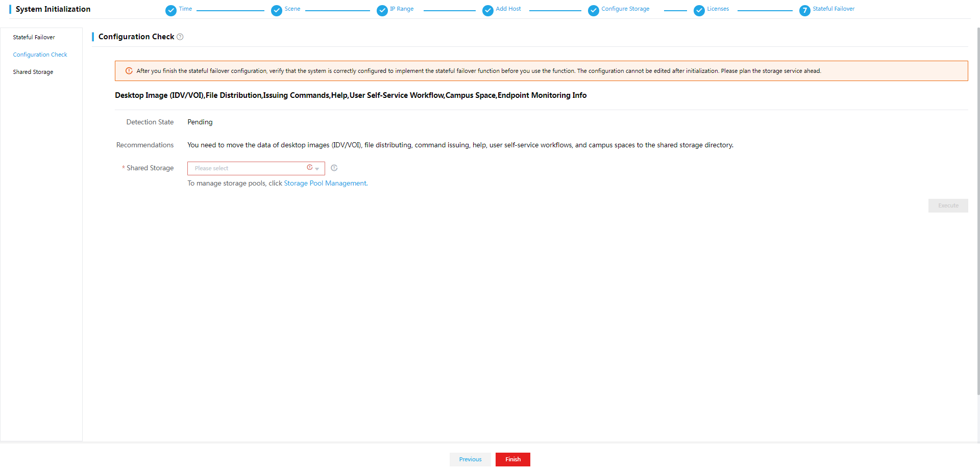
21. Click Configuration Check from the left navigation pane. Rectify the settings that fail the check as prompted and then click OK.
To perform configuration check after Space Console is initialized, select System > Stateful Failover > Configuration Check from the navigation pane.
Figure 76 Stateful failover system setup completed
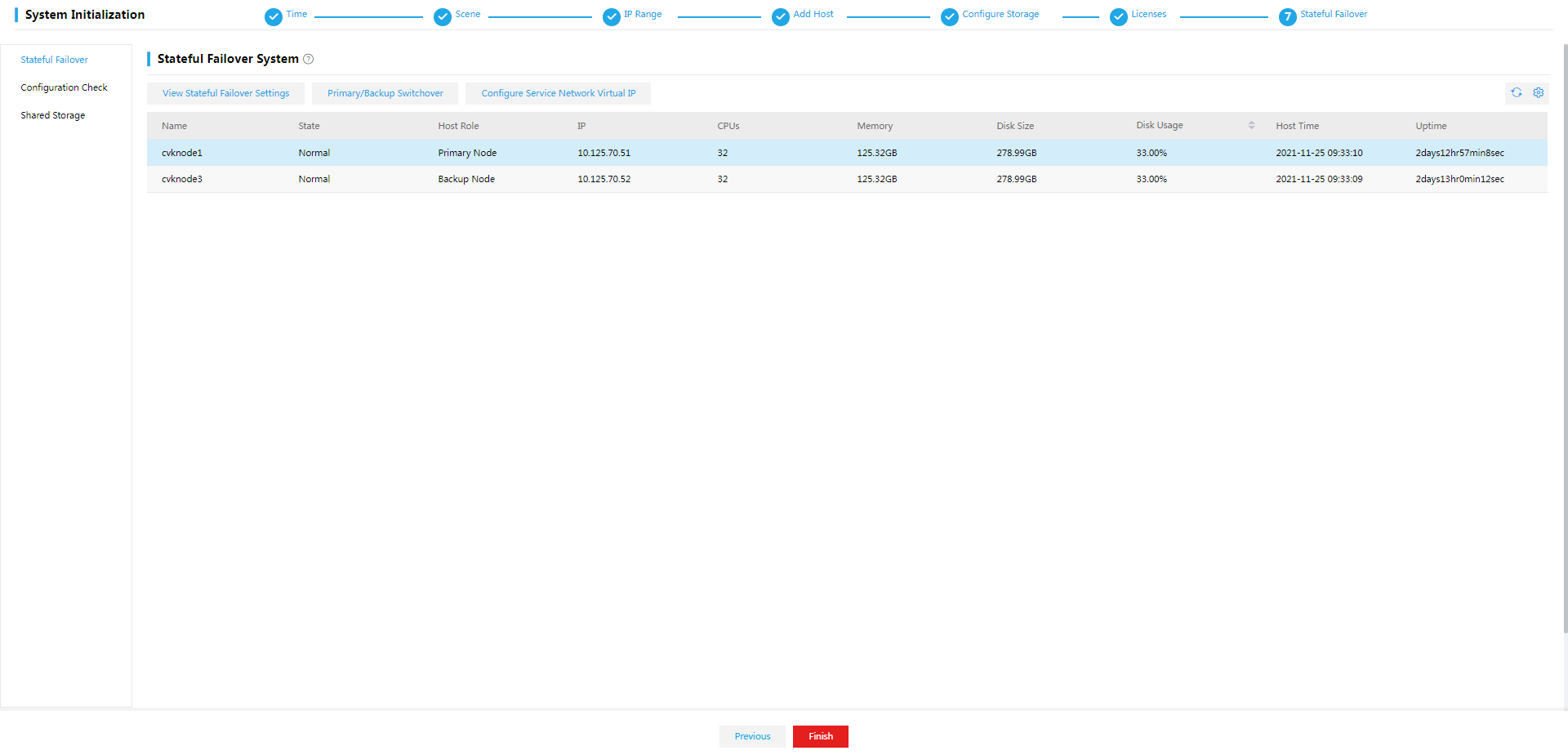
Figure 77 Configuration check result
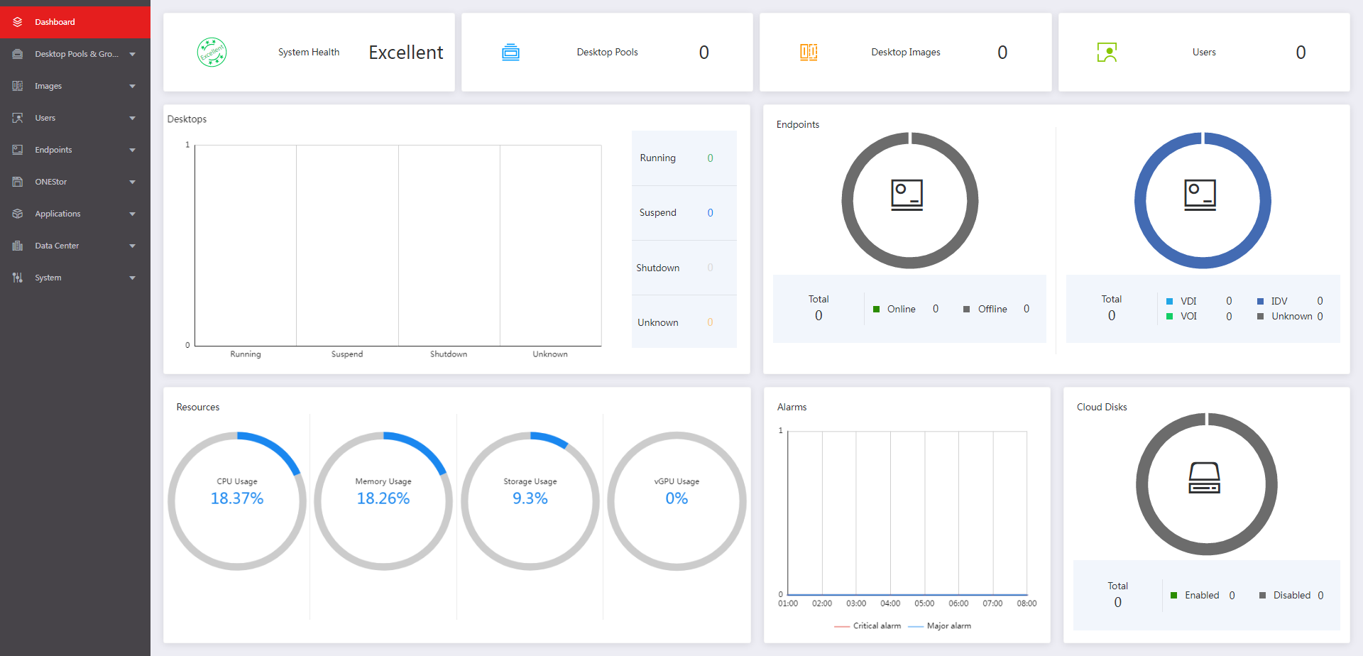
22. Click Finish. The Dashboard page opens.
Figure 78 Dashboard
Two hosts
In a two-host HCI deployment scenario, the two physical servers are used as the compute and storage nodes and a cloud endpoint or VM is used as the external monitor node.
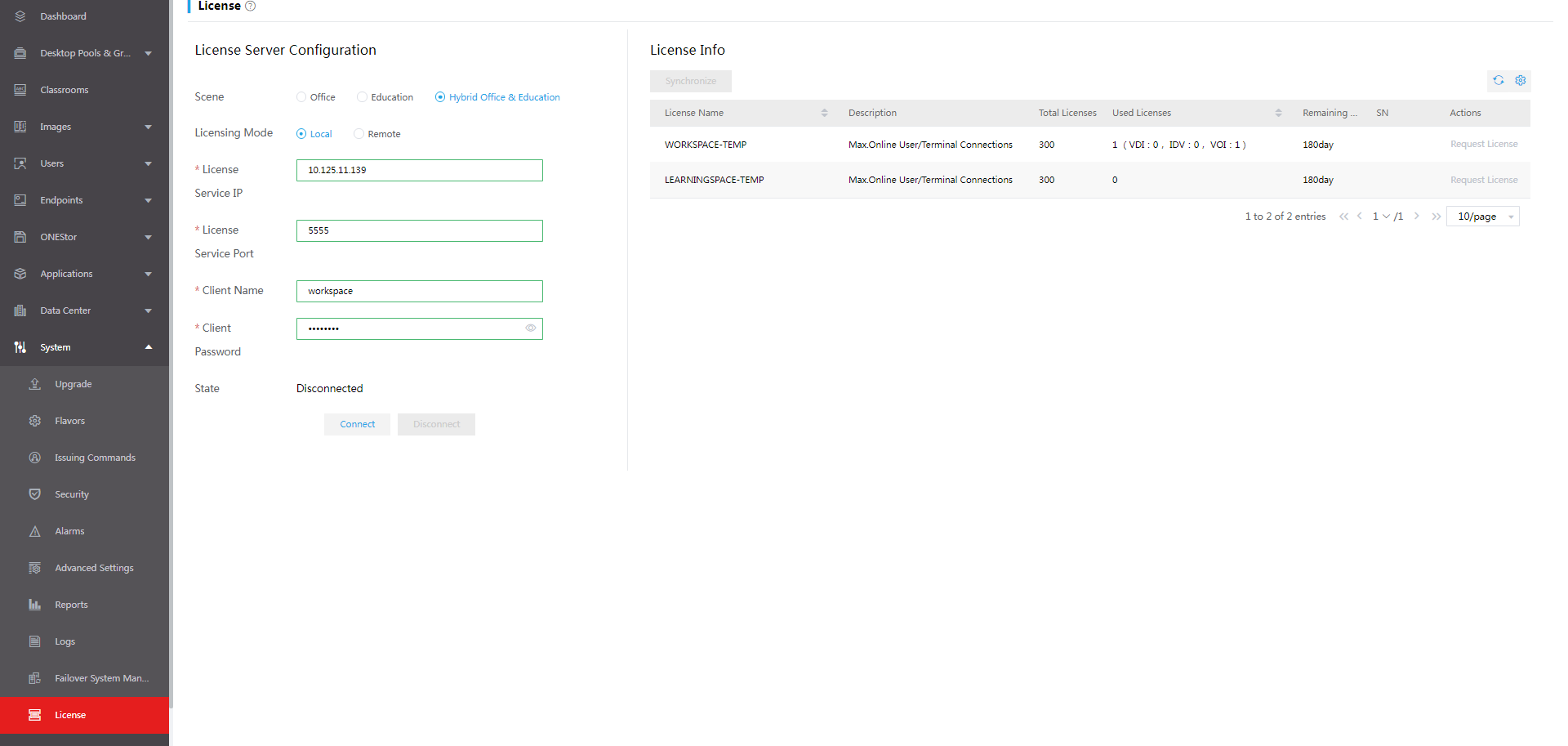
Licensing
Workspace licensing
If Space Console is not managed by CloudOS, select the local licensing mode and specify the license server reachable to Space Console for license management as shown in Figure 79.
Figure 79 Space console local licensing

Figure 80 License User Guide
|
|
IMPORTANT: · As a best practice, set up a license server on a physical server. If no physical server is available, set up the license server on a VM that has similar configuration as a physical server. · Use a license server of E1145 or later for licensing. |
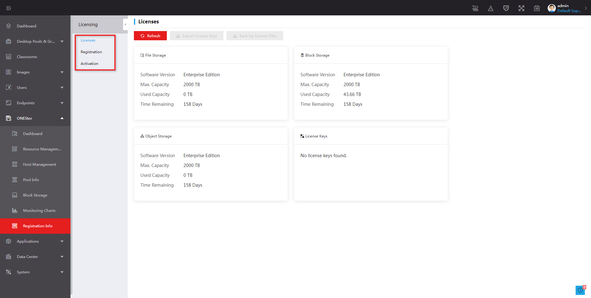
ONEStor licensing
To use ONEStor distributed storage, click ONEStor > Registration Info as shown in Figure 81 to complete license registration and activation.
Figure 81 ONEStor licensing
Installing and deploying Workspace clients in the office scenario
In the office scenario, you can access a Workspace cloud desktop from a VDI, IDV, or VOI client.
Deploying a client on an endpoint registers the endpoint to Space Console. To ensure correct communication between the endpoint and Space Console, do not change the local time of the endpoint after registration.
For endpoints compatible with a specific client, see the release notes for Workspace.
Installing the VDI client
The VDI client supports the following installation methods:
· Automatic installation—With the endpoints are connected to the network and powered on, the GTK-SpaceAgent on the endpoints discovers Space Console and completes the SpaceAgent installation. The automatic installation allows endpoints to discover Space Console through GTK-SpaceAgent and download the compatible VDI client from Space Console for installation. This method is applicable only to H3C designated SpaceOS and UOS endpoints preinstalled with the GTK-SpaceAgent component. For information about H3C designated endpoints, see the release notes for Workspace. For endpoints not installed with GTK-SpaceAgent, see "Installing SpaceAgent" for installation.
· Manual installation—Requires users to download the installation package and install the client manually."
Obtaining the installation packages
Obtain the compressed client installation package from the product release package, and select the required VDI client installation package after unzipping the compressed client package. Then upload the VDI client installation package to Space Console. Table 42 describes the VDI client installation packages and compatible OSs and endpoints.
Table 42 VDI client installation packages
|
VDI client installation packages |
Architecture |
Compatible operating systems |
Compatible endpoints |
Remarks |
|
H3C_Workspace_App-version-win32.zip |
X86 |
Windows |
All (Windows system) |
XP operating systems not supported |
|
H3C_Workspace_App-version-linux-x64.zip |
X86 |
SpaceOS, UOS |
C101LS series, C500 |
N/A |
|
H3C_Workspace_App-version-linux-arm32.zip |
ARM32 |
SpaceOS |
C113 series |
N/A |
|
H3C_Workspace_App-version-UOS-aarch64.zip |
ARM64 |
UOS |
CD2000 |
N/A |
|
H3C_Workspace_App-version-linux-aarch64.zip |
ARM64 |
Kylin |
Galaxy Unicorn endpoints |
N/A |
|
H3C_Workspace_App-version-UOS-mips64el.zip |
MIPS64 |
UOS |
Tsinghua Tongfang Loongson 3A-4000 |
N/A |
Creating an endpoint group
As a best practice, first create an endpoint group before you connect an endpoint to the network. If you do not do so, the system adds the endpoint to the default group.
To create an endpoint group:
1. Log in to Space Console. For more information, see "Configuring and accessing Space Console."
2. From the left navigation pane, select Endpoint > Endpoint.
3. Click the Endpoint Groups tab and then click Create.
4. In the dialog box that opens, configure the following parameters as needed:
¡ Group Type—Select VDI as the group type.
¡ Name—Specify the group name.
¡ Parent Group—Select the parent group.
¡ IP Range—Specify the IP range.
¡ Authentication Mode—Select the authentication mode. With gateway proxy enabled, only the user authentication mode is available.
¡ Client Type—Select Workspace as the client type.
¡ Client Display Mode—Select the client display mode. If you select Default, the full-screen display mode is used for SpaceOS endpoints, cloud desktop endpoints, and third-party cloud endpoints, and the windowed display mode is used for the other endpoints. With gateway proxy enabled, only the default mode is available.
5. Click OK.
Figure 82 Creating an endpoint group
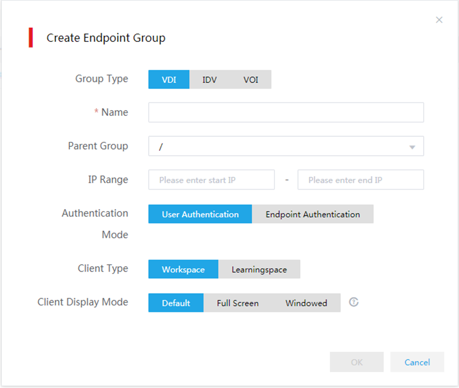
Performing automatic client installation
1. Before powering on the VDI endpoint, upload the SpaceAgent installation package to Space Console. For more information, see "Uploading the client installation package." Enable Upgrade Reminder, and select Now for the Upgrade At parameter .
You must upload the SpaceAgent installation package according to compatible OSs and endpoints. Table 46 describes the SpaceAgent installation package and compatible OSs and endpoints.
2. After the VDI endpoint is started, the system automatically starts GTK-SpaceAgent, and checks the status of the network settings.
If no IP address is detected within 30 seconds, the system pops up the network configuration dialog box on which you can configure static IP settings and DHCP settings.
3. After the environment check is completed, the system displays the Space Console discovery interface. During this process, GTK-SpaceAgent automatically discovers Space Console and requests for an upgrade.
4. If the Space Console discovery times out, or automatic upgrade is not enabled on Space Console,, enter the Space Console IP address, and click Connect. In addition, check for the network connectivity during the process, and upload the SpaceAgent installation package and enable Upgrade Reminder as described in step 1. With Space Console discovered and automatic upgrade enabled on Space Console, GTK-SpaceAgent automatically installs the VDI client.
After the installation is completed, the client is restarted automatically, and you can access the desktop.
To perform automatic client installation, connect the endpoint to the network and then power on the endpoint. Then, the system operates as follows:
1. SpaceAgent on the endpoint discovers Space Consoles and registers the endpoint automatically. The endpoint joins the created endpoint group.
2. Space Console deploys the client to the endpoint based on the configured network settings.
3. The endpoint installs the client and opens the login screen.
As shown in Figure 83, you can use SpaceConfig to view information about the discovered Space Consoles.
Figure 84 Workspace login screen
Installing the client manually (Windows OS)
No officially designated Windows endpoint is provided in the H3C Workspace cloud desktop solution. You can install a VDI client compatible with the Windows system on your endpoint such as a PC.
Software and hardware requirements
Table 43 Software and hardware requirements
|
Operating system |
Minimum hardware requirements |
|
Windows 10 1709 or higher |
· CPU: 4 cores, 2.2 Ghz main frequency · Memory: 3 GB · Drive: 4 GB · NIC: One GE network adapter |
Obtaining the installation package
You can use either of the following ways to obtain the installation package:
· If the client installation package has been uploaded to Space Console, access the Space Console IP:8083/data/version directory from a browser on your endpoint to download the required client installation package.
· Obtain the compressed client package from the product release package, unzip the client compressed package, and copy the required client installation package to the endpoint.
Installing the client
1. Right-click the .exe file and run the program as an administrator.
2. Select English in the Installer Language dialog box, and then click OK.
Figure 85 Selecting a language
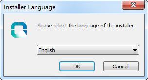
Figure 86 Starting the installation
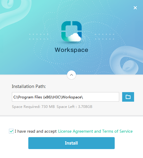
|
|
TIP: During manual installation of Workspace App, SpaceAgent will be installed automatically regardless of whether SpaceAgent has been installed or not. The original SpaceAgent, if any, will be overwritten. |
3. Select the installation path, and then click Install.
4. Click Start.
5. Restart your computer as prompted by the following window.
Figure 87 Restarting the computer
6. The system creates a
Workspace shortcut ![]() on the desktop after the computer is
restarted.
on the desktop after the computer is
restarted.
|
|
TIP: · For how to use a Workspace cloud desktop client, see H3C Workspace Client User Manual (for Office Scenario). · To use the VDI client, make sure the administrator has finished desktop image, authorization policy, and desktop pool configuration from Space Console. For more information, see quick start (office scenario) in the Workspace user manual. · A one-click health check tool is installed simultaneously with the client used for checking the hardware configuration of the endpoint hosting the client. For more information, see H3C Workspace Client User Manual (for Office Scenario). |
Installing a client manually (SpaceOS/UOS)
Obtaining the installation package
You can use either of the following ways to obtain the installation package:
· If the client installation package has been uploaded to Space Console, access the Space Console IP:8083/data/version directory from the browser on your endpoint to download the required client installation package.
· Obtain the compressed client package from the product release package, unzip the client compressed package, and copy the required client installation package to the endpoint.
Installing the client
The following procedure installs an E1010 version of Workspace App. The procedure is similar for installing a later version of Workspace App.
1. Access Menu > System Tools > LXTerminal or press Ctrl+Alt+T to open the LXTerminal CLI.
2. Install the client.
a. Access the folder that saves the installation package.
spaceos@localhost:~$ cd /home/spaceos/Downloads
b. Verify that the package exists in the folder.
spaceos@localhost:~/Downloads$ ll
c. Decompress the installation package.
spaceos@localhost:~/Downloads$ unzip H3C_Workspace_App-E1010-linux-x64.zip
d. Run the installation program as a super administrator.
spaceos@localhost:~/Downloads$ sudo ./install.sh
|
|
TIP: · After the installation package is decompressed, you can also double-click the installer program in the decompressed files to install Workspace App. During the installation process, the installer program will detect whether SpaceAgent has been installed on the endpoint automatically and install SpaceAgent if it is not installed. · For information about how to use the Workspace cloud desktop client, see H3C Workspace Client User Manual (for Office Scenario). · To use the VDI client, make sure the administrator has finished desktop image, authorization policy, and desktop pool configuration from Space Console. For more information, see quick start (office scenario) in the Workspace user manual. |
Installing and deploying the IDV client
Restrictions and guidelines
Make sure the IDV endpoint and the VM running on the endpoint use IP addresses in the same network segment.
To use the IDV client, make sure the administrator has finished desktop image, authorization policy, and desktop pool configuration from Space Console. For more information, see quick start (office scenario) in the Workspace user manual.
Installing the IDV client
IDV client-compatible endpoints and GTK-SpaceAgent are pre-installed with the required operating system and IDV client. With the endpoints connected to the network and powered on, the GTK-SpaceAgent on the endpoints automatically discovers Space Console and completes the IDV client installation. If the version of the preinstalled operating system and client is lower for Space Console, upgrade the operating system and client according to the upgrade instructions in the release notes.
To install the IDV client:
1. Before powering on the IDV endpoint, upload the H3C_IDVAgent-version-linux-x64.zip installation package and the H3C_Spacelauncher_IDV-version-linux-x86_64.zip installation package to Space Console. For more information, see "Uploading the client installation package." Enable Upgrade Reminder, and select Now for the Upgrade At parameter.
2. After the IDV endpoint is started, the system automatically starts GTK-SpaceAgent, and checks the status of the network settings.
If no IP address is detected within 30 seconds, the system pops up the network configuration dialog box on which you can configure static IP settings and DHCP settings.
3. After the environment check is completed, the system displays the Space Console discovery interface. During this process, GTK-SpaceAgent automatically discovers Space Console and requests for an upgrade.
4. If the Space Console discovery times out, or automatic upgrade is not enabled on Space Console, enter the Space Console IP address, and click Connect. In addition, check for the network connectivity during the process, and upload the SpaceAgent installation package and enable Upgrade Reminder as described in step 1.
With Space Console discovered and automatic upgrade enabled on Space Console, GTK-SpaceAgent automatically installs the IDV client.
After the installation is completed, the client is restarted automatically, and you can access the IDV client.
Deploying the IDV client
1. Open the IDV client. The client automatically discovers Space Consoles at the startup and displays available Space Console IP addresses on the screen.
Before registration, the client displays
icon ![]() in the upper right corner, which indicates no
connection with Space Console.
in the upper right corner, which indicates no
connection with Space Console.
Figure 88 Discovering Space Consoles
Figure 89 IP addresses of automatically discovered Space Consoles

2. Select the IP address of the target Space Console, or click Manual input and enter the Space Console IP address, and then click Register. The default port number is 8860.
After registration, the client displays
icon ![]() in the upper right corner, which
indicates that the client has been connected to Space Console.
in the upper right corner, which
indicates that the client has been connected to Space Console.
Figure 90 Entering the IP address of Space Console

The IDV client requests desktop pool and authorization information from Space Console. After Space Console assigns a desktop pool and authorizes the user, the client starts to download image files.
Figure 91 Requesting desktop pool and authorization information

Figure 92 Downloading image files
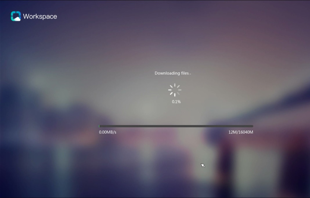
The login screen opens after image downloading. For dedicated-user or multi-user authorization, you must enter the password to log in to the client. For anonymous-user authorization, you will be logged in to the client automatically.
Figure 93 Login screen for dedicated-user authorization
Installing and deploying the VOI client
Restrictions and guidelines
Make sure the VOI endpoint and the client operating system running on the endpoint use the same IP address.
To use the VOI client, make sure the administrator has finished desktop image, authorization policy, and desktop pool configuration from Space Console. For more information, see quick start (office scenario) in the Workspace user manual.
Installing the VOI client
VOI client-compatible endpoints and GTK-SpaceAgent are pre-installed with the required operating system and VOI client. With the endpoints connected to the network and powered on, the GTK-SpaceAgent on the endpoints automatically discovers Space Console and completes the VOI client installation. If the version of the preinstalled operating system and client is lower for Space Console, upgrade the operating system and client according to the upgrade instructions in the release notes.
To install the VOI client:
1. Before powering on the VOI endpoint, upload the H3C_Spacelauncher_VOI_UEFI-version-x86_64.zip installation package to Space Console. For more information, see "Uploading the client installation package." Enable Upgrade Reminder, and select Now for the Upgrade At parameter.
2. After the VOI endpoint is started, the system automatically starts GTK-SpaceAgent, and checks the status of the network settings.
If no IP address is detected within 30 seconds, the system pops up the network configuration dialog box on which you can configure static IP settings and DHCP settings.
3. After the environment check is completed, the system displays the Space Console discovery interface. During this process, GTK-SpaceAgent automatically discovers Space Console and requests for an upgrade.
4. If the Space Console discovery times out, or automatic upgrade is not enabled on Space Console enter the Space Console IP address, and click Connect. In addition, check for the network connectivity during the process, and upload the SpaceAgent installation package and enable Upgrade Reminder as described in step 1.
With Space Console discovered and automatic upgrade enabled on Space Console, GTK-SpaceAgent automatically installs the VOI client.
After the installation is completed, the client is restarted automatically, and you can accesses the VOI client.
Deploying the VOI client
1. Open the VOI client. The client automatically discovers Space Consoles at the first startup and displays available Space Console IP addresses on the screen.
Before registration, the client displays
icon ![]() in the upper right corner, which indicates no
connection to Space Console.
in the upper right corner, which indicates no
connection to Space Console.
Figure 94 Discovering Space Consoles

Figure 95 IP addresses of automatically discovered Space Consoles

2. Select the IP address of the target Space Console, or click Manual input and specify the Space Console IP address. Click Register.
After registration, the client displays
icon ![]() in the upper right corner, which indicates
that the client has been connected to Space Console.
in the upper right corner, which indicates
that the client has been connected to Space Console.
Figure 96 Entering the Space Console IP address

The VOI client requests desktop pool and authorization information from Space Console. After Space Console assigns a desktop pool and authorizes the user, the client starts to download image files.
Figure 97 Requesting desktop pool and authorization information
Figure 98 Downloading image files

|
|
IMPORTANT: If image file download fails because an exception such as network outage occurs, you must restart the endpoint and download the image files again after the issue is resolved. |
The login screen opens after image downloading. For dedicated-user or multi-user authorization, you must enter the password to log in to the client. For anonymous-user authorization, you will be logged in to the client automatically.
Figure 99 Login screen for dedicated-user authorization

Installing and deploying Learningspace clients in the education scenario
Workspace cloud desktop clients for the education scenario include a Learningspace teacher client and a Learningspace student client, which can be used together with classroom management by Mythware.
You can install a Learningspace teacher client on a PC or VDI endpoint, and install a Learningspace student client on a VDI or VOI endpoint.
Installing the Learningspace student client
The Learningspace student client allows students to access student desktops without entering a username or password. Teachers can control the screen display for students as needed from the teacher client.
You can install the Learningspace student client on a VDI or VOI endpoint.
Restrictions and guidelines
Deploying a client on an endpoint registers the endpoint with Space Console. To ensure correct communication between the endpoint and Space Console, do not change the local time of the endpoint after registration.
For endpoints compatible with the student client, see the release notes for Workspace.
Installing the Learningspace student client on a VDI endpoint
Installation methods
VDI endpoints support the following installation methods for the Learningspace student client:
· Automatic installation—Allows endpoints to discover Space Console through SpaceAgent and download the compatible Learningspace student client from Space Console for installation. This method is applicable only to H3C designated VDI endpoints preinstalled with the SpaceAgent component. For information about H3C designated VDI endpoints, see the release notes for Workspace.
· Manual installation—Download and install the Learningspace student client installation package manually.
In a Windows operating system, the system examines if SpaceAgent has been installed on the endpoint during Learningspace student client installation. If SpaceAgent is not installed, you can enable the system to install SpaceAgent simultaneously or install SpaceAgent manually later. For information about manual SpaceAgent installation, see "Installing SpaceAgent on a SpaceOS or UOS endpoint."
Obtaining the installation package
Obtain the compressed client package from the product release package, and select the required VDI student client package after unzipping the compressed client package. Then upload the student client package to Space Console. The following table describes the VDI student client packages and their compatible OSs and endpoints.
Table 44 VDI student client installation packages
|
VDI student client installation package |
Architecture |
Compatible operating systems |
Compatible endpoints |
Remarks |
|
H3C_Learningspace_App-version-win32.zip |
X86 |
Windows |
All (Windows system) |
XP operating systems not supported |
|
H3C_Learningspace_App-version-linux-x64.zip |
X86 |
SpaceOS |
C100 series, C101LS series |
N/A |
|
H3C_Learningspace_App-version-linux-arm32.zip |
ARM32 |
SpaceOS |
C113 series |
N/A |
Creating an endpoint group
As a best practice, first create an endpoint group before you connect an endpoint to the network. If you do not do so, the system adds the endpoint to the default group.
To create an endpoint group:
1. Log in to Space Console. For more information, see "Configuring and accessing Space Console."
2. From the left navigation pane, select Endpoint > Endpoint.
3. Click the Endpoint Groups tab and then click Create.
4. In the dialog box that opens, configure the following parameters as needed:
¡ Group Type—Select VDI as the group type.
¡ Name—Specify the group name.
¡ Parent Group—Select the parent group.
¡ IP Range—Specify the IP range.
¡ Authentication Mode—Select Endpoint authentication.
¡ Client Type—Select Learningspace as the client type.
5. Click OK.
Figure 100 Creating an endpoint group
Performing automatic client installation
1. Before powering on the VDI endpoint, upload the SpaceAgent installation package to Space Console. For more information, see "Uploading the client installation package." Enable Upgrade Reminder, and select Now for the Upgrade At parameter.
You must upload the SpaceAgent installation package according to compatible OSs and endpoints. Table 46 describes the SpaceAgent installation package and compatible OSs and endpoints.
2. After the VDI endpoint is started, the system automatically starts GTK-SpaceAgent, and checks the status of the network settings.
If no IP address is detected within 30 seconds, the system pops up the network configuration dialog box on which you can configure static IP settings and DHCP settings.
3. After the environment check is completed, the system displays the Space Console discovery interface. During this process, GTK-SpaceAgent automatically discovers Space Console and requests for an upgrade.
4. If the Space Console discovery times out, or automatic upgrade is not enabled on Space Console, enter the Space Console IP address, and click Connect. In addition, check for the network connectivity during the process, and determine whether to upload the SpaceAgent installation package and enable Upgrade Reminder as described in step 1.
With Space Console discovered and automatic upgrade enabled on Space Console, GTK-SpaceAgent automatically installs the VDI client.
After the installation is completed, the client is restarted automatically, and you can access the desktop.
5. Connect the endpoint to the network and then power on the endpoint. Then, the system operates as follows:
a. SpaceAgent on the endpoint discovers Space Console and registers the endpoint automatically. The endpoint joins the created endpoint group. You can use SpaceConfig to view information about the discovered Space Console.
Figure 101 SpaceConfig screen

b. Space Console deploys the client to the endpoint based on the configured network settings.
c. The endpoint installs the client and opens the Learningspace student client screen.
Figure 102 Learningspace student client screen
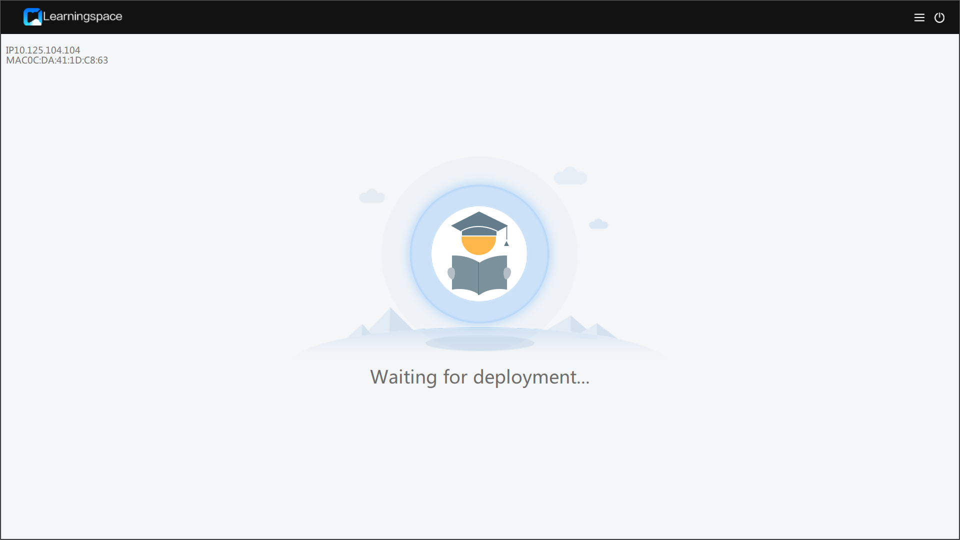
6. Click the ![]() icon
in the upper right corner, click Return
to Local Host, enter the password (Password@1234), and then click the close button in the
upper right corner.
icon
in the upper right corner, click Return
to Local Host, enter the password (Password@1234), and then click the close button in the
upper right corner.
For information about how to use the Learningspace student client, see H3C Workspace Student Client User Guide (for Education Scenario).
Figure 103 Return to local Host
Installing the client manually (Windows OS)
You can use either of the following ways to obtain the installation package:
· If the client installation package has been uploaded to Space Console, access the Space Console IP:8083/data/version directory from your browser to download the required client installation package.
· Obtain the compressed client package from the product release package, unzip the client compressed package, and copy the required client installation package to the endpoint.
To install the client:
1. Decompress the H3C_Learningspace_App-version-win32.zip installation package and then run the H3C_Learningspace_App-version-win32.exe program as an administrator.
2. Select English, and then click OK.
Figure 104 Selecting a language

3. Select VDI as the endpoint type, select the student client as the client type, and then click Next.
Figure 105 Selecting the endpoint type and client type
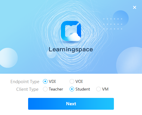
4. Select the installation directory, and then click Install.
|
|
NOTE: · To run the Learningspace client in a Windows operating system, you can only install it on drive C. · During the installation process, the specific version of SpaceAgent will be installed automatically regardless of whether SpaceAgent has been installed or not. The original SpaceAgent, if any, will be overwritten. |
Figure 106 Selecting the installation directory
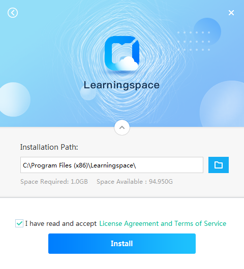
5. Click Finish when the installation is complete. The Learningspace student client opens.
6. Click the ![]() icon in the upper
right corner, click Return to Local Host, enter the
password (Password@1234), and then click the close
icon in the upper right corner.
icon in the upper
right corner, click Return to Local Host, enter the
password (Password@1234), and then click the close
icon in the upper right corner.
The student client shortcut ![]() is displayed on the desktop. For information about how to use the
Learningspace student client, see H3C Workspace Student Client User Guide (for Education
Scenario).
is displayed on the desktop. For information about how to use the
Learningspace student client, see H3C Workspace Student Client User Guide (for Education
Scenario).
Figure 107 Waiting for deployment

Figure 108 Returning to local host

Installing the client manually (SpaceOS)
You can use either of the following ways to obtain the installation package:
· If the client installation package has been uploaded to Space Console, access the Space Console IP:8083/data/version directory from your browser to download the required client installation package.
· Obtain the compressed client package from the product release package, unzip the client compressed package, and copy the required client installation package to the endpoint.
To install the client manually:
1. Click the gear icon in the lower right corner and select System Tools > LXTerminal to open the LXTerminal CLI. Alternatively, press Ctrl+Alt+T to open the LXTerminal CLI.
2. Install the client.
a. Access the folder that saves the installation package.
spaceos@localhost:~$ cd /home/spaceos/Downloads
b. Verify that the package exists in the folder.
spaceos@localhost:~/Downloads$ ll
c. Decompress the installation package.
spaceos@localhost:~/Downloads$ unzip H3C_Workspace_App-E1011-linux-x64.zip
d. Execute the installation program as the super administrator.
spaceos@localhost:~/Downloads$ sudo ./install.sh
3. Space Console deploys the client to the endpoint based on the configured network settings.
4. The endpoint installs the client and opens the Learningspace student client screen.
Figure 109 Learningspace student client screen

5. Click the ![]() icon
in the upper right corner, click Return
to Local Host, enter the password (Password@1234), and then click the close icon in the
upper right corner.
icon
in the upper right corner, click Return
to Local Host, enter the password (Password@1234), and then click the close icon in the
upper right corner.
For information about how to use the Learningspace student client, see H3C Workspace Student Client User Guide (for Education Scenario).
Figure 110 Returning to the local host
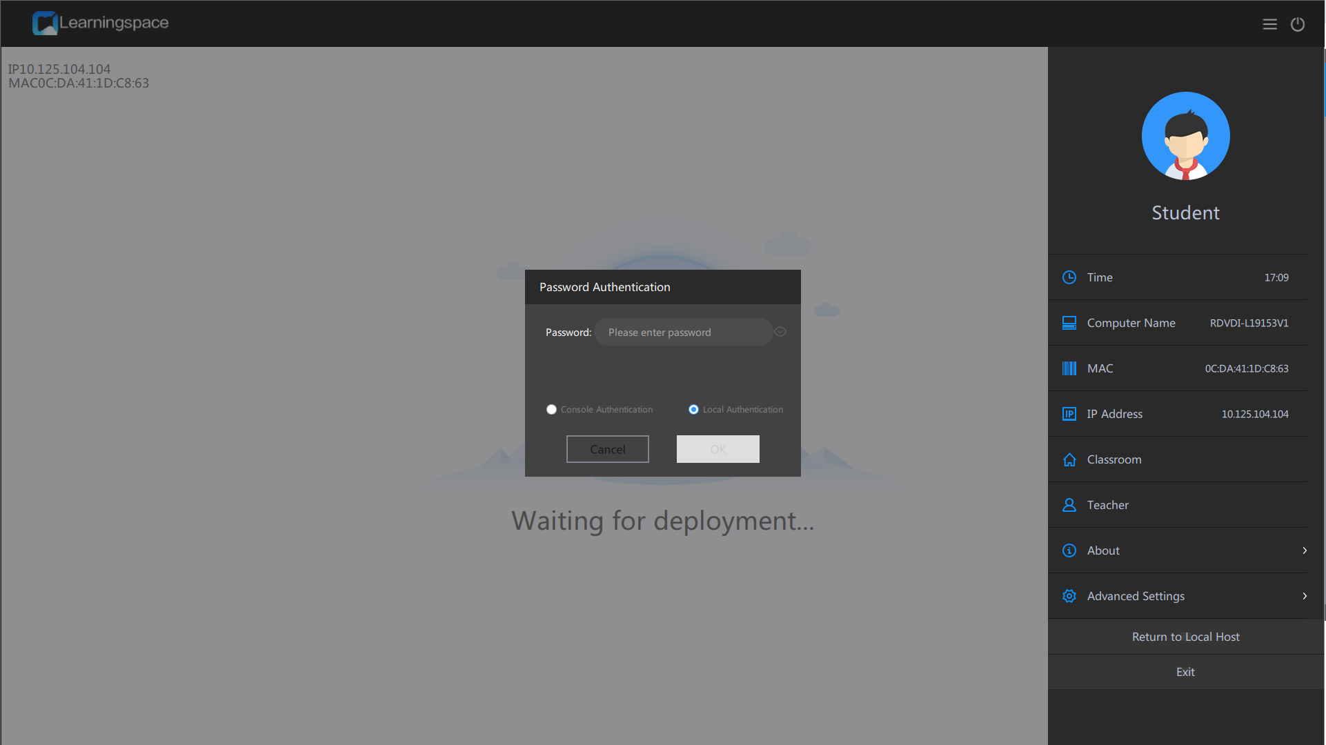
|
|
NOTE: For information about how to use the student client, see H3C Workspace Cloud Desktop Student User Manual (Educational Scenario). |
Installing the Learningspace student client on a VOI endpoint
On a VOI endpoint, install the Learningspace student client in a course VM. For more information, see building a VOI course in the Workspace user manual.
Installing the Learningspace teacher client
The Learningspace teacher client allows teachers to give lessons, manage student clients, manage homework, and access teaching management software.
For the hardware requirements for installing the Learningspace teacher client, see Figure 115. As a best practice, use the recommended hardware configuration.
Restrictions and guidelines
To install the Learningspace teacher client, use the Windows 7 SP1 enterprise edition or Windows 10 1909 enterprise edition as a best practice.
To use a Windows 7 operating system, make sure the endpoint is installed with Microsoft.Net Framework 4.6 or a higher version.
Obtaining the installation package
The Learningspace teacher client must be installed manually. Table 45 shows the VDI teacher client installation packages and compatible OSs and endpoints.
Table 45 VDI teacher client installation packages
|
VDI teacher client installation package |
Architecture |
Compatible operating systems |
Compatible endpoints |
Remarks |
|
H3C_Learningspace_App-version-win32.zip |
X86 |
Windows |
All |
XP systems not supported |
You can use either of the following ways to obtain the installation package:
· If the client installation package has been uploaded to Space Console, access the Space Console IP:8083/data/version directory from your browser to download the required client installation package.
· Obtain the compressed client package from the product release package, unzip the client compressed package, and copy the required client installation package to the endpoint.
Procedure
1. Decompress the H3C_Learningspace_App-version-win32.zip installation package and then run the H3C_Learningspace_App-version-win32.exe program as an administrator.
2. Select English, and then click OK. The installation wizard opens.
Figure 111 Selecting a language
3. Select VDI as the endpoint type, select the teacher client as the client type, and then click Next.
Figure 112 Selecting the endpoint type and client type
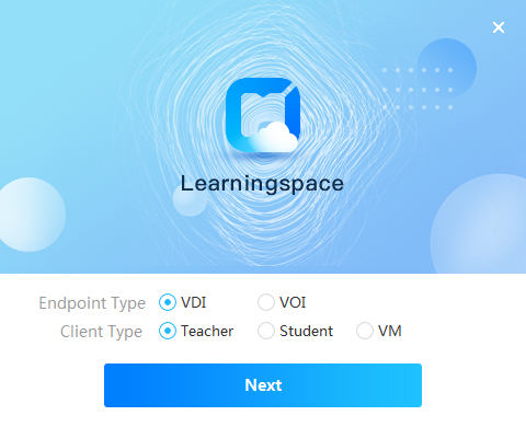
4. Select the installation directory, and then click Install.
|
|
NOTE: · To run the Learningspace client in a Windows operating system, you can only install it on drive C. · During the installation process, the specific version of SpaceAgent will be installed automatically regardless of whether SpaceAgent has been installed or not. The original SpaceAgent, if any, will be overwritten. |
Figure 113 Selecting the installation directory
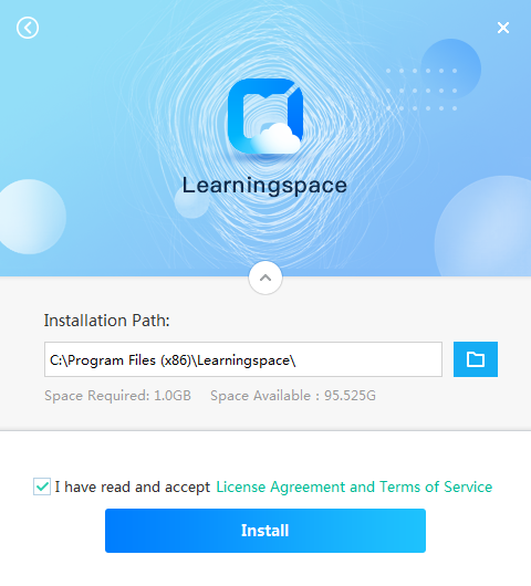
5. Click Finish.
Figure 114 Installation completion
The teacher client shortcut ![]() is
displayed on the desktop. For
information about how to use the teacher client, see H3C
Workspace Teacher Client User Guide (for Education Scenario).
is
displayed on the desktop. For
information about how to use the teacher client, see H3C
Workspace Teacher Client User Guide (for Education Scenario).
Deploying student endpoints
H3C Learningspace supports VDI and VOI student endpoints. After the installation of a student endpoint, deploy it for interoperation with the teacher client.
Deploying a VDI student endpoint
You can deploy a VDI student endpoint to a classroom from Space Console or the teacher client.
To deploy a VDI student endpoint to a classroom from Space Console:
1. From the left navigation pane, select Classrooms.
2. Select a classroom.
3. Click the Endpoints tab.
4. Click Select Client and then add the student client to the classroom.
To deploy a VDI student endpoint from the teacher client:
1. Double click the teacher client shortcut ![]() to run the teacher client.
to run the teacher client.
The client examines hardware configurations of the endpoint hosting the client.
In the hardware configuration window, verify that the configuration meets client requirements. Click OK.
Figure 115 Hardware configuration check

2. In the dialog box that opens, select the network node, specify the IP address of Space Console, select a classroom, click Register, and then click OK.
Figure 116 Teacher client settings

3. Enter the username and password and log in to the teacher client.
Figure 117 Teacher client login page

4. Perform the following tasks to access the endpoint maintenance page.
a. From the left navigation pane of the teacher client screen, select Classroom.
b. On the Classroom tab, click More and select Maintenance.
c. Enter the password for endpoint authentication and click Authentication. The default password is Password@1234.
Figure 118 Maintenance menu

Figure 119 Endpoint password authentication
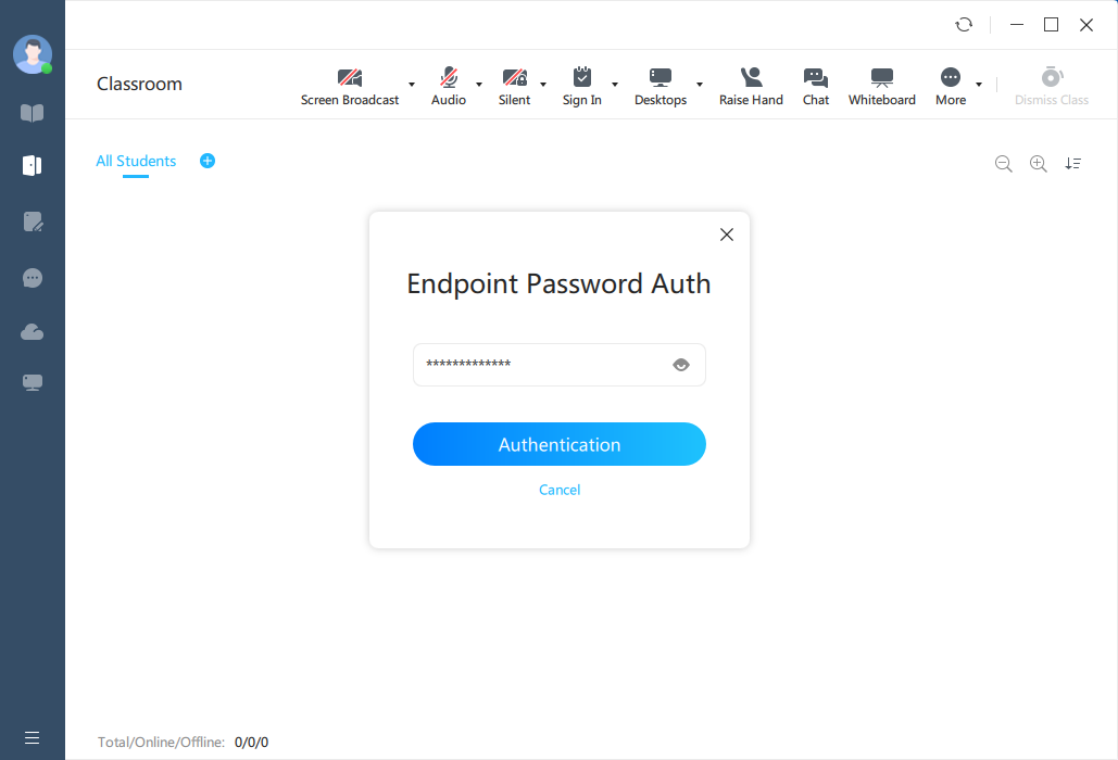
5. On the Endpoint Deployment tab, click Start Searching.
Figure 120 Searching for endpoints to deploy
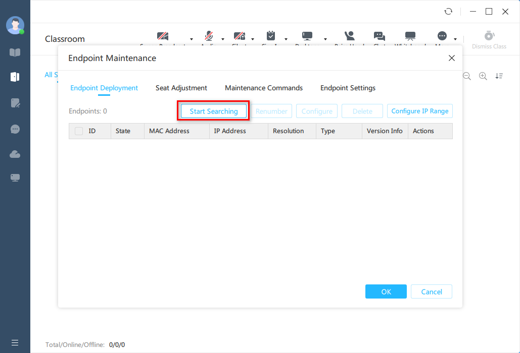
The system displays discovered endpoints in the list.
Figure 121 Discovered endpoints
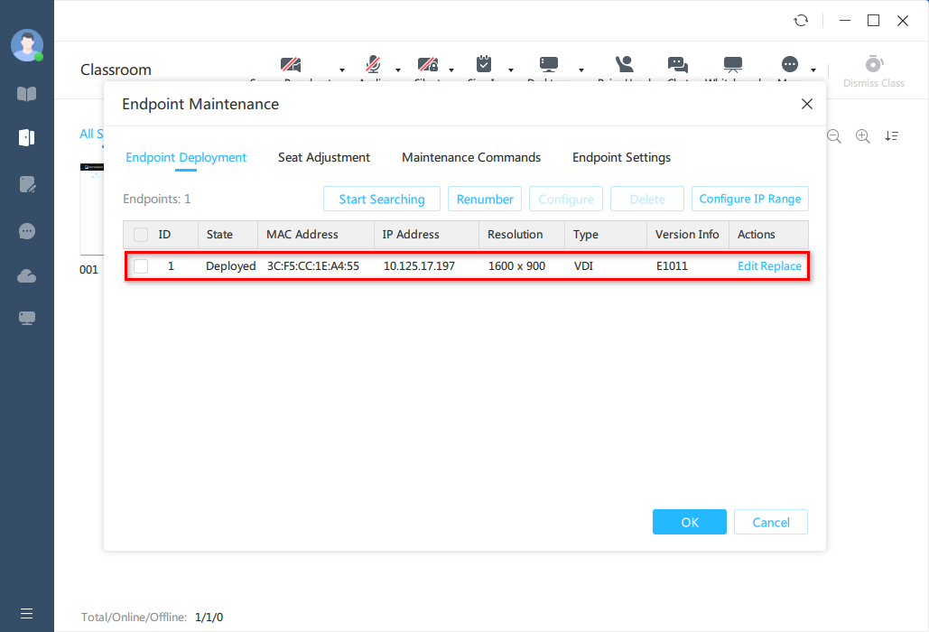
6. Select the endpoints that do not need deployment, click Delete, and then click OK.
After deployment, the system prompts information uploading success and students can take courses through the deployed clients.
Deploying a VOI student endpoint
You can deploy a VOI endpoint to a classroom from Space Console or the teacher client. After deployment, the VOI endpoint will automatically download the default courses of the classroom.
Restrictions and guidelines
Before deploying a VOI student endpoint to a classroom, make sure you have finished default course creation for the classroom. For more information, see building a VOI course in the Workspace user manual.
Make sure the VOI endpoint and the client operating system running on the endpoint use the same IP address.
H3C designated VOI endpoints are pre-installed with the VOI client. After connecting to Space Console, the endpoints examine the VOI client version and update the client automatically if Space Console has a later version of the client. For information about H3C designated VOI endpoints, see the release notes for Workspace.
Creating an VOI endpoint group
1. Log in to Space Console. For more information, see "Configuring and accessing Space Console."
2. From the left navigation pane, select Endpoint > Endpoint.
3. Click the Endpoint Groups tab and then click Create.
Figure 122 Endpoint group list
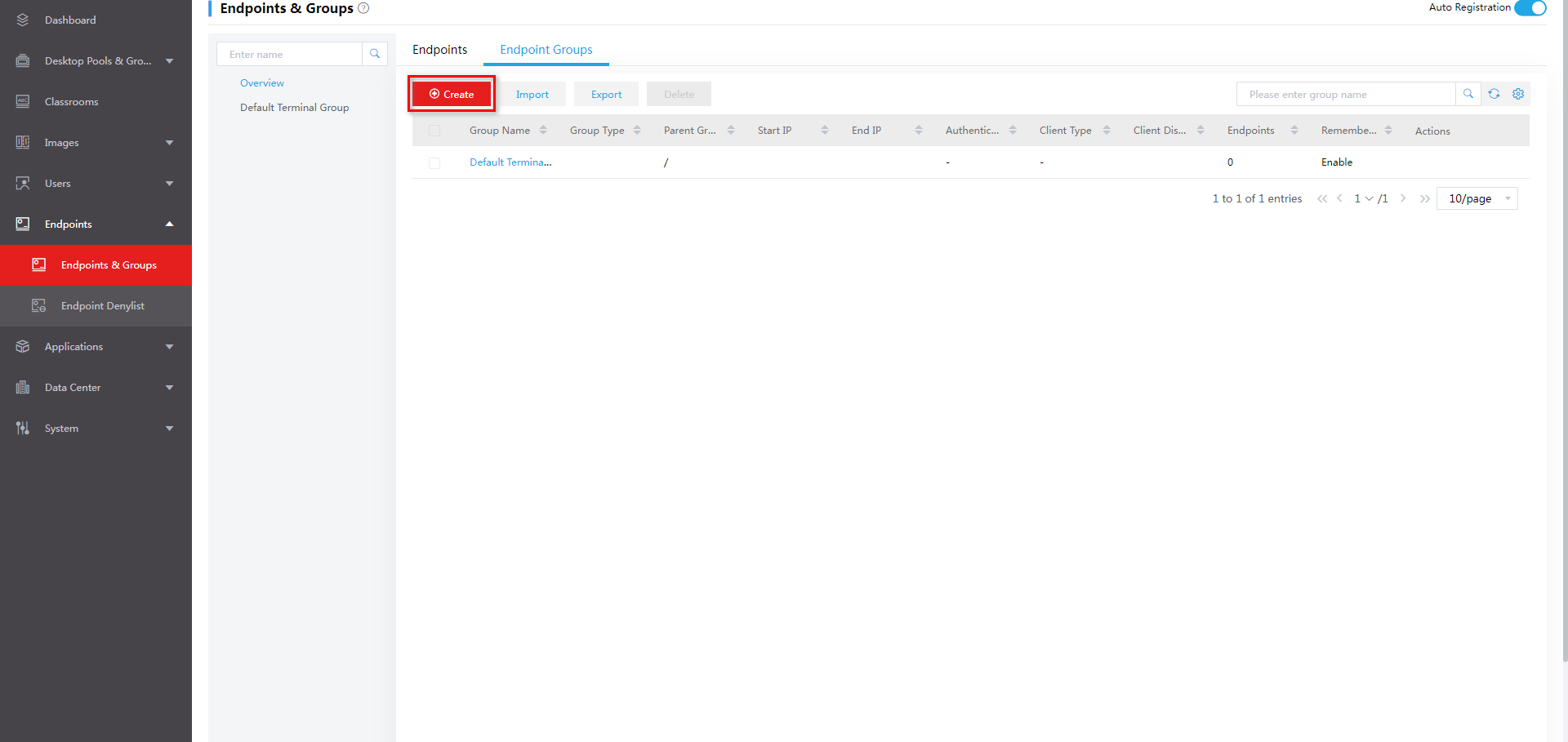
4. In the dialog box that opens, configure the following parameters as needed:
¡ Group Type—Select VOI as the group type.
¡ Name—Specify the group name.
¡ Parent Group—Select the parent group.
¡ Client Type—Select Learningspace as the client type.
Figure 123 Creating an endpoint group
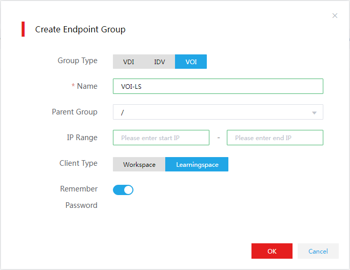
5. Click OK.
Installing the VOI client
VOI client-compatible endpoints and GTK-SpaceAgent are pre-installed with the required operating system and VOI client. With the endpoints connected to the network and powered on, the GTK-SpaceAgent on the endpoints automatically discovers Space Console and completes the VOI client installation. If the version of the preinstalled operating system and client is lower for Space Console, upgrade the operating system and client according to the upgrade instructions in the release notes.
To install the VOI client:
1. Before powering on the VOI endpoint, upload the H3C_Spacelauncher_VOI_UEFI-version-x86_64.zip installation package to Space Console. For more information, see "Uploading the client installation package." Enable Upgrade Reminder, and select Now for the Upgrade At parameter.
2. After the VOI endpoint is started, the system automatically starts GTK-SpaceAgent, and checks the status of the network settings.
If no IP address is detected within 30 seconds, the system pops up the network configuration dialog box on which you can configure static IP settings and DHCP settings.
3. After the environment check is completed, the system displays the Space Console discovery interface. During this process, GTK-SpaceAgent automatically discovers Space Console and requests for an upgrade for Space Console.
4. If the Space Console discovery times out, or automatic upgrade is not enabled on Space Console, enter the Space Console IP address, and click Connect. In addition, check for the network connectivity during the process, and upload the SpaceAgent installation package and enable Upgrade Reminder as described in step 1.
With Space Console discovered and automatic upgrade enabled on Space Console, GTK-SpaceAgent automatically installs the VOI client.
After the installation is completed, the client is restarted automatically, and you can access the VOI client.
Deploying an VOI endpoint
1. Open the VOI client. The client automatically discovers Space Consoles through DHCP at the first startup and display available Space Console IP addresses on the screen.
Before registration, the client displays
icon ![]() in the upper right corner, which indicates no
connection to Space Console.
in the upper right corner, which indicates no
connection to Space Console.
Figure 124 Discovering Space Consoles

Figure 125 IP addresses of automatically discovered Space Consoles
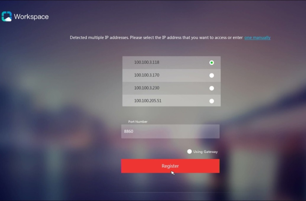
2. Select the IP address of the target Space Console, or click one manually and specify the Space Console IP address. Click Register.
After registration, the client displays
icon ![]() in the upper right corner, which
indicates that the client has been connected to Space Console.
in the upper right corner, which
indicates that the client has been connected to Space Console.
Figure 126 Inputting the Space Console IP address
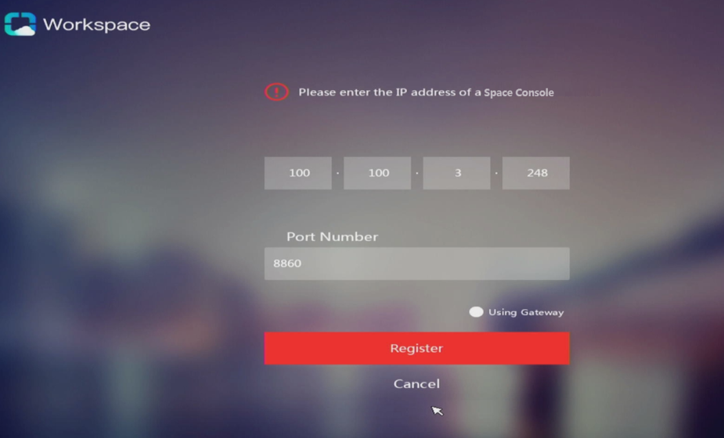
The VOI client requests desktop pool and authorization information from Space Console.
Figure 127 Requesting desktop pool and authorization information

3. Access the Endpoint Groups page of Space Console, and add the endpoint to the created VOI endpoint group.
You can view information about the endpoint in the Endpoint Groups list.
Figure 128 Adding the endpoint to the VOI endpoint group
4. Restart the endpoint. The endpoint will be automatically updated as a Learningspace client.
Figure 129 Automatically updated as a Learningspace client

You can repeat the previous steps to deploy all VOI student endpoints and then proceed to connect the student endpoints to the teacher client.
5. Double click the teacher client shortcut ![]() to run the teacher client.
to run the teacher client.
The client examines hardware configurations of the endpoint hosting the client.
In the hardware configuration window, verify that the configuration meets client requirements. Click OK.
|
|
NOTE: You can also deploy a VOI student endpoint to a classroom from Space Console. The procedure is similar as that for the VDI student endpoint. For more information, see "Deploying a VDI student endpoint." After a VOI endpoint is deployed to a classroom, it will automatically download the default courses of the classroom. |
Figure 130 Hardware configuration check
6. In the dialog box that opens, select the network node, specify the IP address of Space Console, select a classroom, click Register, and then click OK.
Figure 131 Teacher client settings
7. Enter the username and password and log in to the teacher client.
Figure 132 Teacher client login page
8. Perform the following tasks to access the endpoint maintenance page.
a. From the left navigation pane of the teacher client screen, select Classroom.
b. On the Classroom tab, click More and select Maintenance.
c. Enter the password for endpoint authentication and click Authentication.
The default password is Password@1234.
Figure 133 Maintenance menu
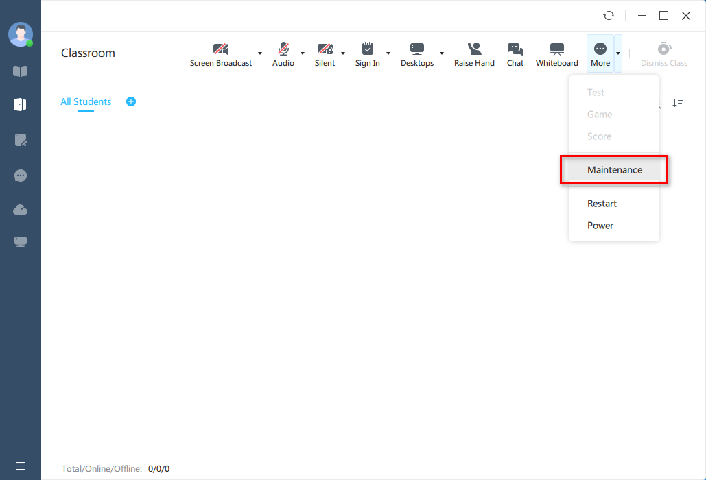
Figure 134 Endpoint password authentication

9. On the Endpoint Deployment tab, click Start Searching.
Figure 135 Searching for endpoints to deploy

The system displays discovered endpoints in the list.
Figure 136 Discovered endpoints

10. Select the endpoints that do not need deployment, click Delete, and then click OK.
After deployment, the system prompts information uploading success and students can take courses through the deployed clients.
|
|
NOTE: After a VOI endpoint is deployed to a classroom, it will automatically download the default courses of the classroom. |
Troubleshooting cloud desktop installation
Black screen error occurs during Space Console installation
To solve this issue:
1. Access the installation screen. Then press E to enter edit mode.
Figure 137 Accessing the installation screen
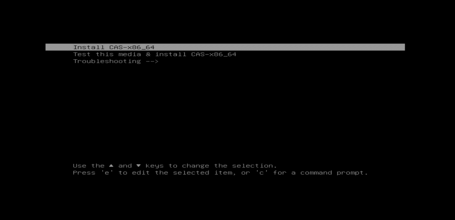
2. Add string inst.graphical inst.xdriver=fbdev video=efifb:off video=VGA-1:1024x768@60me console=tty0 to the end of the linuxefi or linux line.
Figure 138 Adding a string to the linuxefi or linux line
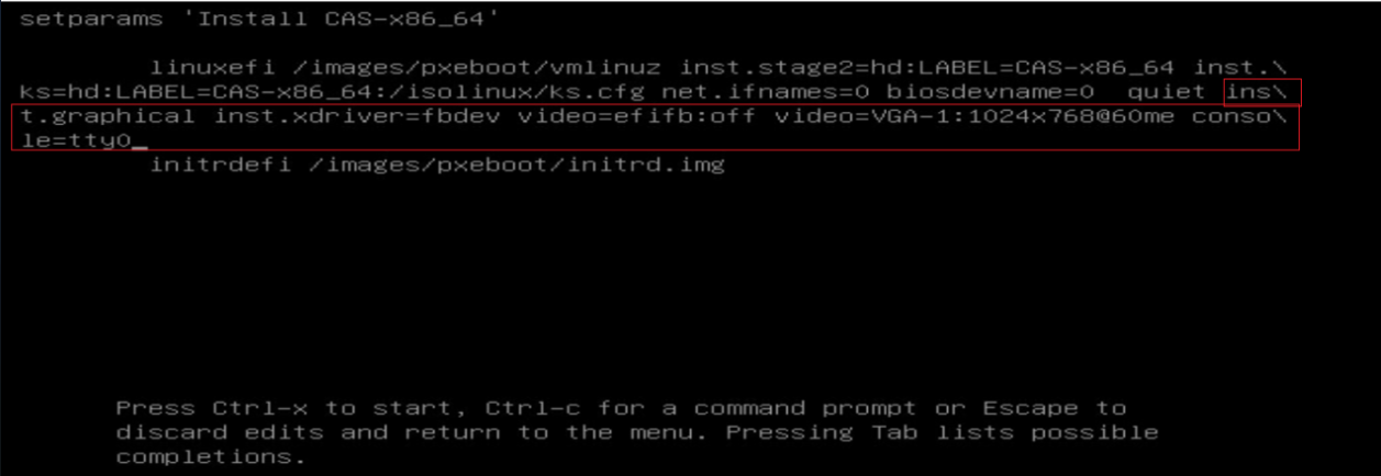
3. Press Ctrl + X to start installation.
Appendixes
Uploading the client installation package
The client installation package is an independent compressed package separated from the Space Console installation package. After the deployment or upgrade of Space Console, you are required to upload the client installation package from the Upgrade Management page on Space Console for manual or automatic client installation.
To upload the client installation package:
1. Obtain the compressed client package from the product installation package and then copy it to a PC or client.
2. Decompress the H3C_Workspace-version-Clients.tar.gz package. Figure 1 shows the decompressed client installation packages. In this example, the E1011L06 version of installation packages are used.
Figure 139 Client installation packages (x86)
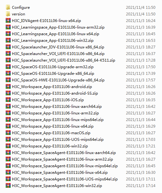
3. Log in to Space Console. Select System > Upgrade > Upgrade Management and then click Upgrade Configuration.
Figure 140 Upgrade management page
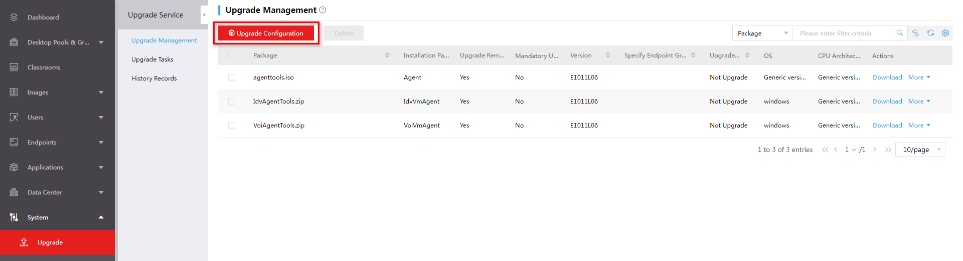
4. Click Upload. In the dialog box that opens, select the client installation packages and then click Upload.
Figure 141 Uploading the client installation package
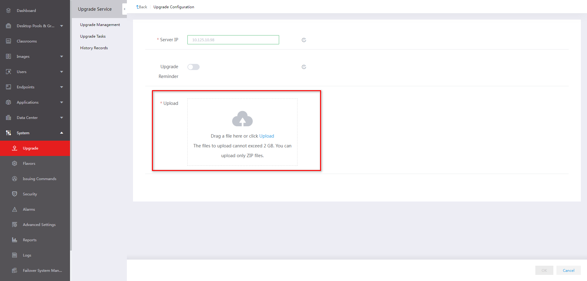
5. Click OK after the uploading is complete. The uploaded client installation packages are displayed on the Upload Management page.
Figure 142 Uploading completed
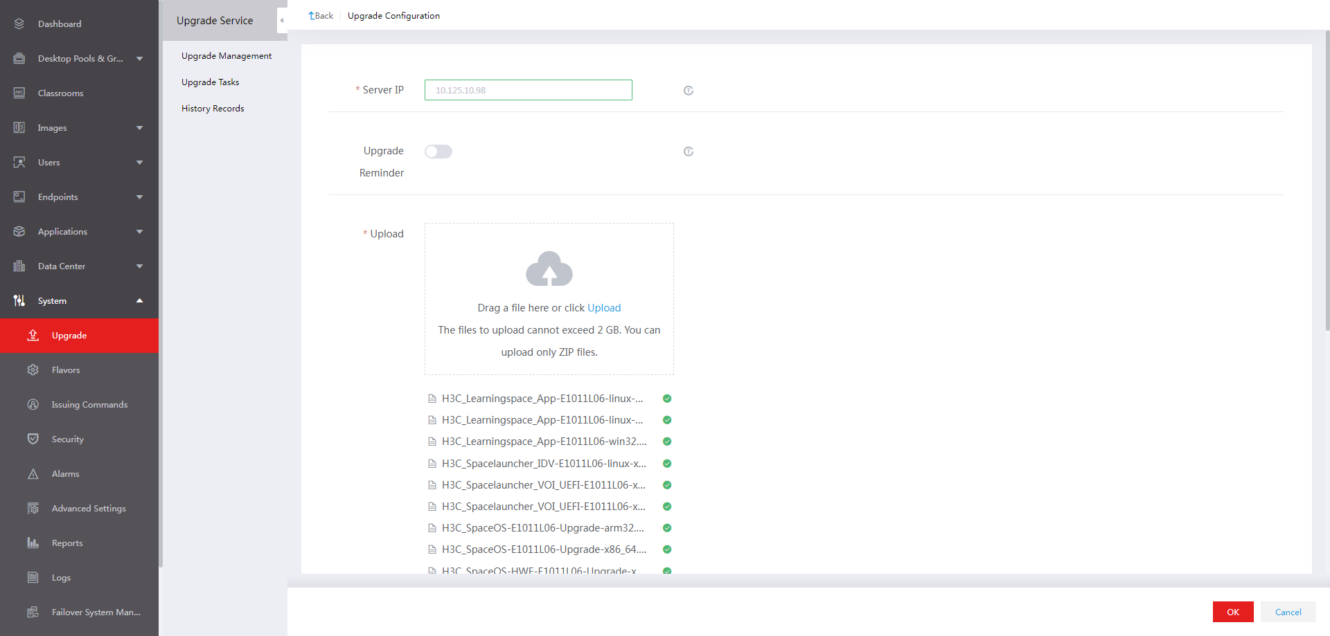
Figure 143 Installation packages uploaded successfully
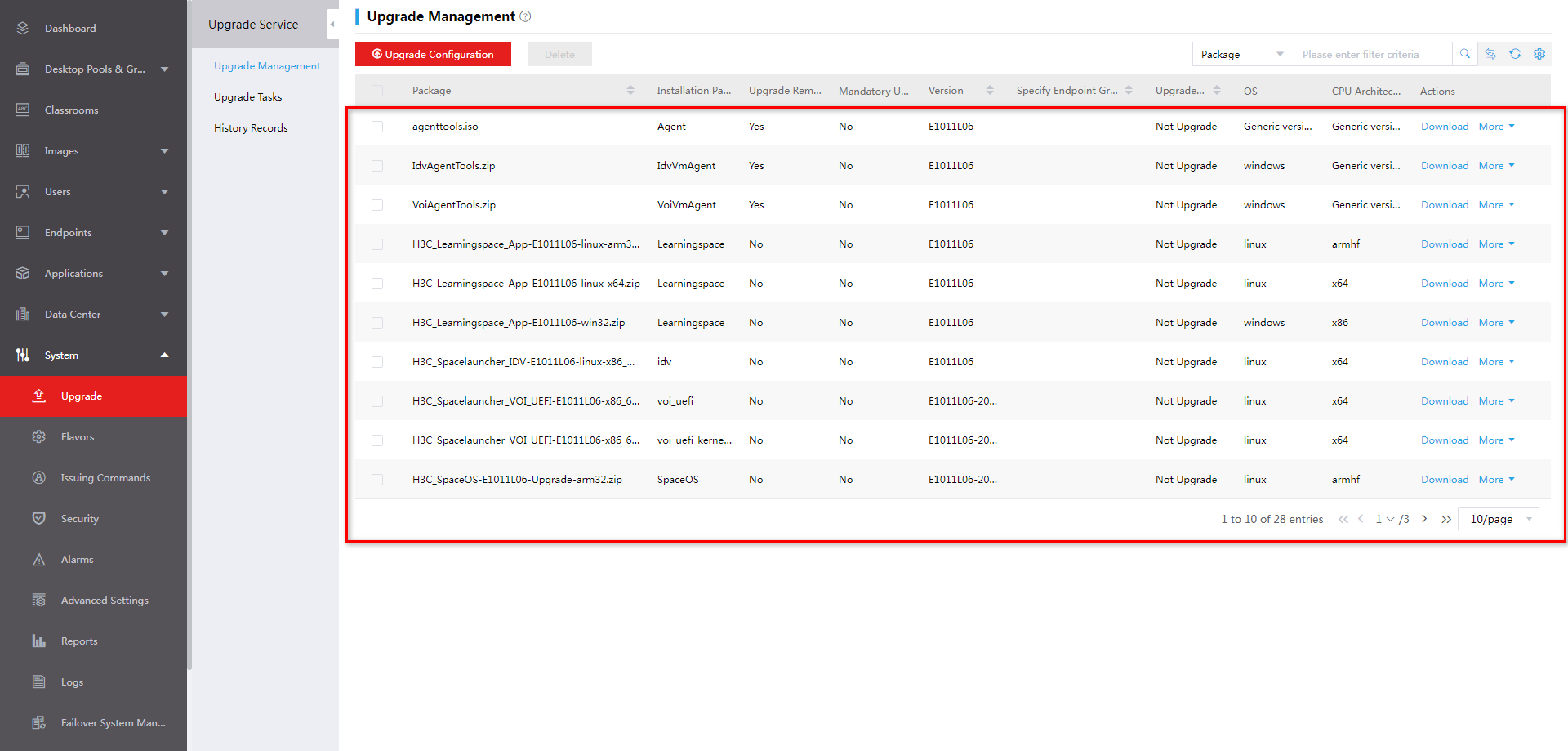
Uninstalling the VDI Workspace client manually
Uninstalling the client on a Windows endpoint
1. Open the Control Plane and select Programs > Programs and Features.
2. Select the Workspace application, for example, Workspace, and then click Uninstall or Uninstall/Change.
3. To uninstall the Workspace client, enter the uninstallation password. By default, the password is Password@1234.
4. In the dialog box that opens, select whether to retain the data, and then click Yes.
5. Click Finish.
Uninstalling the client on a SpaceOS or UOS endpoint
1. Access Menu > System Tools > LXTerminal or press Ctrl+Alt+T to open the LXTerminal CLI.
2. Use commands to uninstall the client. In this example, the client version is E1011L06.
a. Access the client installation folder.
:~$ cd /userdata/H3C/Workspace/E1011L06
b. Verify that the installation files exist in the folder.
:/userdata/H3C/Workspace/E1011L06$ ll
c. Uninstall the program as a super administrator.
: /userdata/H3C/Workspace/E1011L06$ sudo ./uninstall.sh
Installing SpaceAgent
Obtaining the installation package
Table 46 describes the SpaceAgent installation packages and compatible OSs and endpoints.
Table 46 SpaceAgent installation packages
|
Installation package |
Architecture |
Compatible OS |
Compatible endpoints |
Remarks |
|
H3C_Workspace_SpaceAgent-version-win32.zip |
X86 |
Windows |
All (Windows system) |
XP systems not supported |
|
H3C_Workspace_SpaceAgent-version-linux-x64.zip |
X86 |
SpaceOS, UOS |
C101LS series, C500 |
N/A |
|
H3C_Workspace_SpaceAgent-version-linux-arm32.zip |
ARM32 |
SpaceOS |
C113 series |
N/A |
|
H3C_Workspace_SpaceAgent-version-linux-aarch64.zip |
Arm64 |
UOS, Kylin |
CD2000, Galaxy Kylin endpoint |
N/A |
|
H3C_Workspace_SpaceAgent-version-UOS-mips64el.zip |
MIPS64 |
UOS |
Tsinghua Tongfang Loongson 3A-4000 |
N/A |
You can use either of the following ways to obtain the installation packages:
· Upload the client installation package and then access the Space Console IP:8083/data/version directory from the browser of your endpoint to download the required SpaceAgent installation package.
· Obtain the compressed client package from the product release package, unzip the client compressed package, and copy the required SpaceAgent installation package to the endpoint.
Installing SpaceAgent on a Windows endpoint
1. Obtain the installation package (H3C_Workspace_SpaceAgent-version-win32.zip) at space_console_IP:8083/data/version.
2. Decompress the installation package.
3. Run the installation program H3C_Workspace_SpaceAgent-version-win32.exe.
If SpaceAgent has been installed, select whether to uninstall it.
4. In the installation wizard, click Next.
5. Select the installation directory, and then click Install.
6. Click Finish.
Installing SpaceAgent on a SpaceOS or UOS endpoint
The following procedure installs SpaceAgent on a SpaceOS endpoint. The installation on a UOS endpoint uses the similar procedure.
1. Access Menu > System Tools > LXTerminal or press Ctrl+Alt+T to open the LXTerminal CLI.
2. Decompress the installation package and run the installation program. In this example, the SpaceAgent version is E1011L06.
a. Access the folder that saves the installation package.
:~$ cd /home/spaceos/Downloads
b. Verify that the package exists in the folder.
:~/Downloads$ ll
c. Decompress the installation package.
:~/Downloads# unzip H3C_Workspace_SpaceAgent-E1011L06-linux-x64.zip
d. Run the installation program as a super administrator.
:~/Downloads# sudo ./install.sh
Uninstalling SpaceAgent
Uninstalling SpaceAgent on a Windows endpoint
1. Open the Control Plane and select Programs > Programs and Features.
2. Select the SpaceAgent application, for example, SpaceAgent E1011L06, and then click Uninstall or Uninstall/Change.
3. In the dialog box that opens, select whether to retain user data and confirm the operation.
After uninstallation, the system prompts the operation result.
Uninstalling SpaceAgent from a SpaceOS or UOS endpoint
The following procedure uninstalls SpaceAgent from a SpaceOS endpoint. The uninstallation from a UOS endpoint uses the similar procedure.
1. Access Menu > System Tools > LXTerminal or press Ctrl+Alt+T to open the LXTerminal CLI.
2. Uninstall SpaceAgent:
a. Access the folder that saves the installation package.
:~$ cd /userdata/H3C/SpaceAgent
b. Uninstall SpaceAgent as a super administrator.
:/userdata/H3C/SpaceAgent# sudo ./uninstall.sh
Uninstalling a Learningspace client
Uninstalling a Learningspace client on a Windows endpoint
1. Open the Control Plane and select Programs > Programs and Features.
2. Select the Learningspace application, for example, Learningspace, and then click Uninstall or Uninstall/Change.
3. To uninstall the student client, enter the uninstallation password.
If the student client has been registered with Space Console, the password is the endpoint management password of Space Console. If the student client has not been registered with Space Console, the default password is Password@1234.
After uninstallation, the Learningspace client shortcut on the desktop will be removed.
4. Restart the system for the uninstallation to take effect.
Uninstalling the Learningspace student client on a SpaceOS endpoint
1. Access Menu > System Tools > LXTerminal or press Ctrl+Alt+T to open the LXTerminal CLI.
2. Uninstall a Learningspace client:
a. Access the folder that saves the installation package. In this example, the client version is E1011L06.
:~$ cd /userdata/H3C/Workspace/E1011L06
b. Uninstall the client as a super administrator.
: /userdata/H3C/Workspace/E1011L06$ sudo ./uninstall.sh
After uninstallation, the Learningspace client shortcut on the desktop will be removed.
3. Restart the system for the uninstallation to take effect.
Hardware requirements for a management server that can operate only as a management node
Table 47 Hardware requirements for a management server (separate deployment mode)
|
Item |
Minimum requirements |
|
CPU |
Intel processor, 2.0 GHz base frequency. |
|
Memory |
128 GB |
|
System disks |
Two 600GB 10K RPM SAS HDDs. As a best practice, configure the two disks in RAID 1. |
|
NICs |
One 4-port GE NIC + one two-port 10-GE NIC. |
The CPUs must support hardware-assisted virtualization technology. To use an x86 server, make sure its CPUs support Intel-VT.
You cannot specify a management server in separate deployment mode as a service node.
For stateful failover deployment, make sure the two management servers are the same in configuration.
