- Table of Contents
- Related Documents
-
| Title | Size | Download |
|---|---|---|
| 01-VXLAN configuration | 1008.16 KB |
Generic VXLAN network establishment and forwarding process
VXLAN tunnel establishment and assignment
Assignment of traffic to VXLANs
Configuring basic VXLAN features
Manually creating a VXLAN tunnel
Enabling BFD on a VXLAN tunnel
Manually assigning VXLAN tunnels to a VXLAN
Assigning customer frames to a VSI
About MAC address entry management
Configuring static remote-MAC address entries
Disabling remote-MAC address learning
Setting the destination UDP port number of VXLAN packets
Setting the source UDP port number of VXLAN packets
Configuring VXLAN packet check
Confining unknown-unicast floods to the local site
Enabling ARP flood suppression
Enabling VXLAN packet statistics
Enabling packet statistics for a VSI
Enable packet statistics for all VXLAN tunnels of a VSI
Enabling VXLAN fast forwarding
Display and maintenance commands for VXLANs
Example: Configuring a unicast-mode VXLAN
VXLAN IP gateways separated from VTEPs
Centralized VXLAN IP gateway deployment
Centralized VXLAN gateway group deployment
Distributed VXLAN IP gateway deployment
VXLAN IP gateway support for VSI subinterfaces
Restrictions and guidelines: VXLAN IP gateway configuration
VXLAN IP gateway tasks at a glance
Prerequisites for VXLAN IP gateway configuration
Configuring a centralized VXLAN IP gateway
Configuring a gateway interface on a centralized VXLAN IP gateway
Configuring a centralized VXLAN IP gateway group
Specifying a VTEP group as the gateway for an access layer VTEP
Configuring a distributed VXLAN IP gateway
Restrictions and guidelines for distributed VXLAN IP gateway configuration
Configuring a gateway interface on a distributed VXLAN IP gateway
Enabling dynamic ARP entry synchronization for distributed VXLAN IP gateways
Configuring a VSI subinterface on a VXLAN IP gateway
Disabling remote ARP learning for VXLANs
Configuring a VSI interface or VSI subinterface
Configuring optional parameters for a VSI interface or VSI subinterface
Restoring the default settings of the VSI interface or VSI subinterface
Applying a QoS policy to a VSI interface
Display and maintenance commands for VXLAN IP gateways
VXLAN IP gateway configuration examples
Example: Configuring a centralized VXLAN IP gateway
Example: Configuring distributed VXLAN IPv4 gateways
Example: Configuring distributed VXLAN IPv6 gateways
Example: Configuring a VSI subinterface on a centralized VXLAN IP gateway
Intra-VXLAN traffic forwarding between sites
Inter-VXLAN traffic forwarding between sites
Configuring a VXLAN-DCI tunnel
Assigning a VXLAN-DCI tunnel to a VXLAN
Configuring a gateway interface on an ED
Enabling packet statistics for manually created VXLAN-DCI tunnels
Display and maintenance commands for VXLAN-DCI
VXLAN-DCI configuration examples
Example: Configuring a basic VXLAN-DCI network
Configuring the VTEP as an OVSDB VTEP
Restrictions and guidelines: OVSDB VTEP configuration
Prerequisites for OVSDB VTEP configuration
Setting up an OVSDB connection to a controller
Restrictions and guidelines for OVSDB controller connection setup
Prerequisites for OVSDB controller connection setup
Configuring active SSL connection settings
Configuring passive SSL connection settings
Configuring active TCP connection settings
Configuring passive TCP connection settings
Enabling the OVSDB VTEP service
Specifying a global source address for VXLAN tunnels
Enabling flood proxy on multicast VXLAN tunnels
OVSDB VTEP configuration examples
Example: Configuring a unicast-mode VXLAN
Example: Configuring flood proxy for a VXLAN
VXLAN overview
Virtual eXtensible LAN (VXLAN) is a MAC-in-UDP technology that provides Layer 2 connectivity between distant network sites across an IP network. VXLAN is typically used in data centers for multitenant services.
VXLAN benefits
VXLAN provides the following benefits:
· Support for more virtual switched domains than VLANs—Each VXLAN is uniquely identified by a 24-bit VXLAN ID. The total number of VXLANs can reach 16777216 (224). This specification makes VXLAN a better choice than 802.1Q VLAN to isolate traffic for user terminals.
· Easy deployment and maintenance—VXLAN requires deployment only on the edge devices of the transport network. Devices in the transport network perform typical Layer 3 forwarding.
VXLAN network model
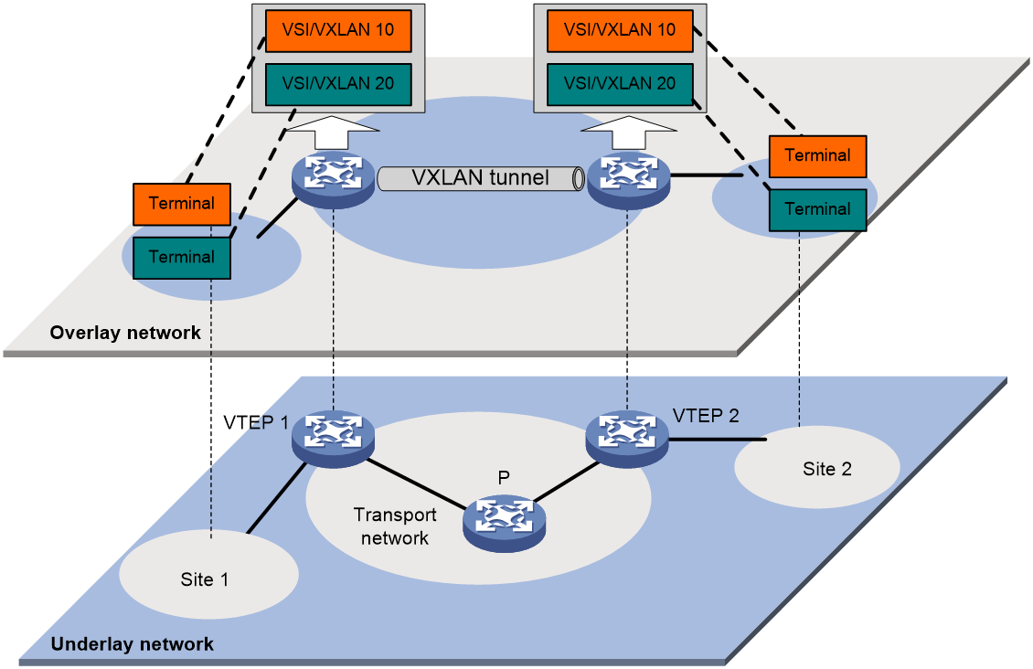
As shown in Figure 1, a VXLAN is a virtual Layer 2 network (known as the overlay network) built on top of an existing physical Layer 3 network (known as the underlay network). The overlay network encapsulates inter-site Layer 2 frames into VXLAN packets and forwards the packets to the destination along the Layer 3 forwarding paths provided by the underlay network. The underlay network is transparent to tenants, and geographically dispersed sites of a tenant are merged into a Layer 2 network.
The transport edge devices assign user terminals to different VXLANs, and then forward traffic between sites for user terminals by using VXLAN tunnels. Supported user terminals include PCs, wireless terminals, and VMs on servers.
|
|
NOTE: This document uses VMs as examples to describe the mechanisms of VXLAN. The mechanisms do not differ between different kinds of user terminals. |
The transport edge devices are VXLAN tunnel endpoints (VTEP). The VTEP implementation of the device uses ACs, VSIs, and VXLAN tunnels to provide VXLAN services.
· VSI—A virtual switch instance is a virtual Layer 2 switched domain. Each VSI provides switching services only for one VXLAN. VSIs learn MAC addresses and forward frames independently of one another. VMs in different sites have Layer 2 connectivity if they are in the same VXLAN.
· Attachment circuit (AC)—An AC is a physical or virtual link that connects a VTEP to a local site. Typically, ACs are site-facing Layer 3 interfaces that are associated with the VSI of a VXLAN. Traffic received from an AC is assigned to the VSI associated with the AC.
· VXLAN tunnel—Logical point-to-point tunnels between VTEPs over the transport network. Each VXLAN tunnel can trunk multiple VXLANs.
VTEPs encapsulate VXLAN traffic in the VXLAN, outer UDP, and outer IP headers. The devices in the transport network forward VXLAN traffic only based on the outer IP header.
Figure 1 VXLAN network model
VXLAN packet format
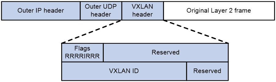
As shown in Figure 2, a VTEP encapsulates a frame in the following headers:
· 8-byte VXLAN header—VXLAN information for the frame.
¡ Flags—If the I bit is 1, the VXLAN ID is valid. If the I bit is 0, the VXLAN ID is invalid. All other bits are reserved and set to 0.
¡ 24-bit VXLAN ID—Identifies the VXLAN of the frame. It is also called the virtual network identifier (VNI).
· 8-byte outer UDP header for VXLAN—The default VXLAN destination UDP port number is 4789.
· 20-byte outer IPv4 or 40-byte outer IPv6 header—Valid addresses of VTEPs or VXLAN multicast groups on the transport network. Devices in the transport network forward VXLAN packets based on the outer IP header.
Figure 2 VXLAN packet format
VXLAN working mechanisms
Generic VXLAN network establishment and forwarding process
The VTEP uses the following process to establish the VXLAN network and forward an inter-site frame:
1. Discovers remote VTEPs, establishes VXLAN tunnels, and assigns the VXLAN tunnels to VXLANs.
2. Assigns the frame to its matching VXLAN if the frame is sent between sites.
3. Performs MAC learning on the VXLAN's VSI.
4. Forwards the frame through VXLAN tunnels.
This section describes this process in detail. For intra-site frames in a VSI, the system performs typical Layer 2 forwarding, and it processes 802.1Q VLAN tags as described in "Access modes of VSIs."
VXLAN tunnel establishment and assignment
To provide Layer 2 connectivity for a VXLAN between two sites, you must create a VXLAN tunnel between the sites and assign the tunnel to the VXLAN.
VXLAN tunnel establishment
VXLAN supports manual and automatic VXLAN tunnel establishment.
· Manual creation—Manually create a VXLAN tunnel interface, and specify the tunnel source and destination IP addresses on the peer VTEPs.
· Automatic creation—Configure the Ethernet Virtual Private Network (EVPN) to automatically discover VTEPs and set up VXLAN tunnels. For more information about EVPN, see EVPN Configuration Guide.
VXLAN tunnel assignment
VXLAN supports manual and automatic VXLAN tunnel assignment.
· Manual assignment—Manually assign VXLAN tunnels to VXLANs.
· Automatic assignment—Run EVPN to automatically assign VXLAN tunnels to VXLANs. For more information about EVPN, see EVPN Configuration Guide.
Assignment of traffic to VXLANs
Traffic from the local site to a remote site
The VTEP uses Layer 3 interface-to-VSI mapping to assign customer frames to a VXLAN. This method maps a site-facing Layer 3 interface to a VSI. The VTEP assigns all frames received from the interface to the VXLAN of the VSI.
Traffic from a remote site to the local site
When a frame arrives at a VXLAN tunnel, the VTEP uses the VXLAN ID in the frame to identify its VXLAN.
MAC learning
The VTEP performs source MAC learning on the VSI as a Layer 2 switch.
· For traffic from the local site to the remote site, the VTEP learns the source MAC address before VXLAN encapsulation.
· For traffic from the remote site to the local site, the VTEP learns the source MAC address after removing the VXLAN header.
A VSI's MAC address table includes the following types of MAC address entries:
· Local MAC—MAC entries dynamically learned from the local site. The outgoing interfaces for the MAC address entries are site-facing interfaces. VXLAN does not support static local-MAC entries.
· Remote MAC—MAC entries learned from a remote site. The outgoing interfaces for the MAC addresses are VXLAN tunnel interfaces.
¡ Static—Manually added MAC entries.
¡ Dynamic—MAC entries learned in the data plane from incoming traffic on VXLAN tunnels. The learned MAC addresses are contained in the inner Ethernet header.
¡ BGP EVPN—MAC entries advertised through BGP EVPN. For more information, see EVPN Configuration Guide.
¡ OpenFlow—MAC entries issued by a remote controller through OpenFlow. For more information, see OpenFlow Configuration Guide.
¡ OVSDB—MAC entries issued by a remote controller through OVSDB.
The following shows the priority order of different types of remote MAC address entries:
a. Static MAC address entries, and MAC address entries issued by a remote controller through OpenFlow or OVSDB. These types of entries have the same priority and overwrite each other.
b. MAC address entries advertised through BGP EVPN.
c. Dynamic MAC address entries.
Unicast forwarding
Intra-site unicast forwarding
The VTEP uses the following process to forward a known unicast frame within a site:
1. Identifies the VSI of the frame.
2. Looks up the destination MAC address in the VSI's MAC address table for the outgoing interface.
3. Sends the frame out of the matching outgoing interface.
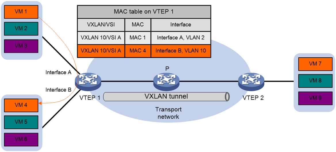
As shown in Figure 3, VTEP 1 forwards a frame from VM 1 to VM 4 within the local site in VLAN 10 as follows:
1. Identifies that the frame belongs to VSI A when the frame arrives at Interface A.
2. Looks up the destination MAC address (MAC 4) in the MAC address table of VSI A for the outgoing interface.
3. Sends the frame out of the matching outgoing interface (Interface B) to VM 4 in VLAN 10.
Inter-site unicast forwarding
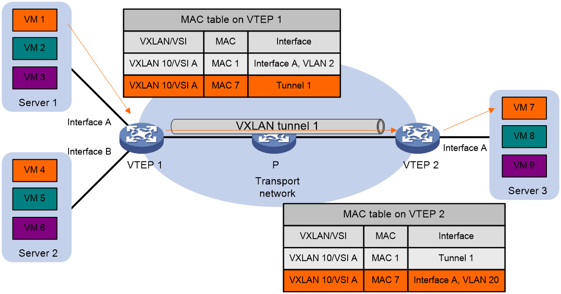
The following process (see Figure 4) applies to a known unicast frame between sites:
1. The source VTEP encapsulates the Ethernet frame in the VXLAN/UDP/IP header.
In the outer IP header, the source IP address is the source VTEP's VXLAN tunnel source IP address. The destination IP address is the VXLAN tunnel destination IP address.
2. The source VTEP forwards the encapsulated packet out of the outgoing VXLAN tunnel interface found in the VSI's MAC address table.
3. The intermediate transport devices (P devices) forward the frame to the destination VTEP by using the outer IP header.
4. The destination VTEP removes the headers on top of the inner Ethernet frame. It then performs MAC address table lookup in the VXLAN's VSI to forward the frame out of the matching outgoing interface.
Flood
The source VTEP floods a broadcast, multicast, or unknown unicast frame to all site-facing interfaces and VXLAN tunnels in the VXLAN, except for the incoming interface. Each destination VTEP floods the inner Ethernet frame to all site-facing interfaces in the VXLAN. To avoid loops, the destination VTEPs do not flood the frame back to VXLAN tunnels.
VXLAN supports unicast mode (also called head-end replication) and flood proxy mode for flood traffic. Multicast mode (also called tandem replication) is not supported in the current software version.
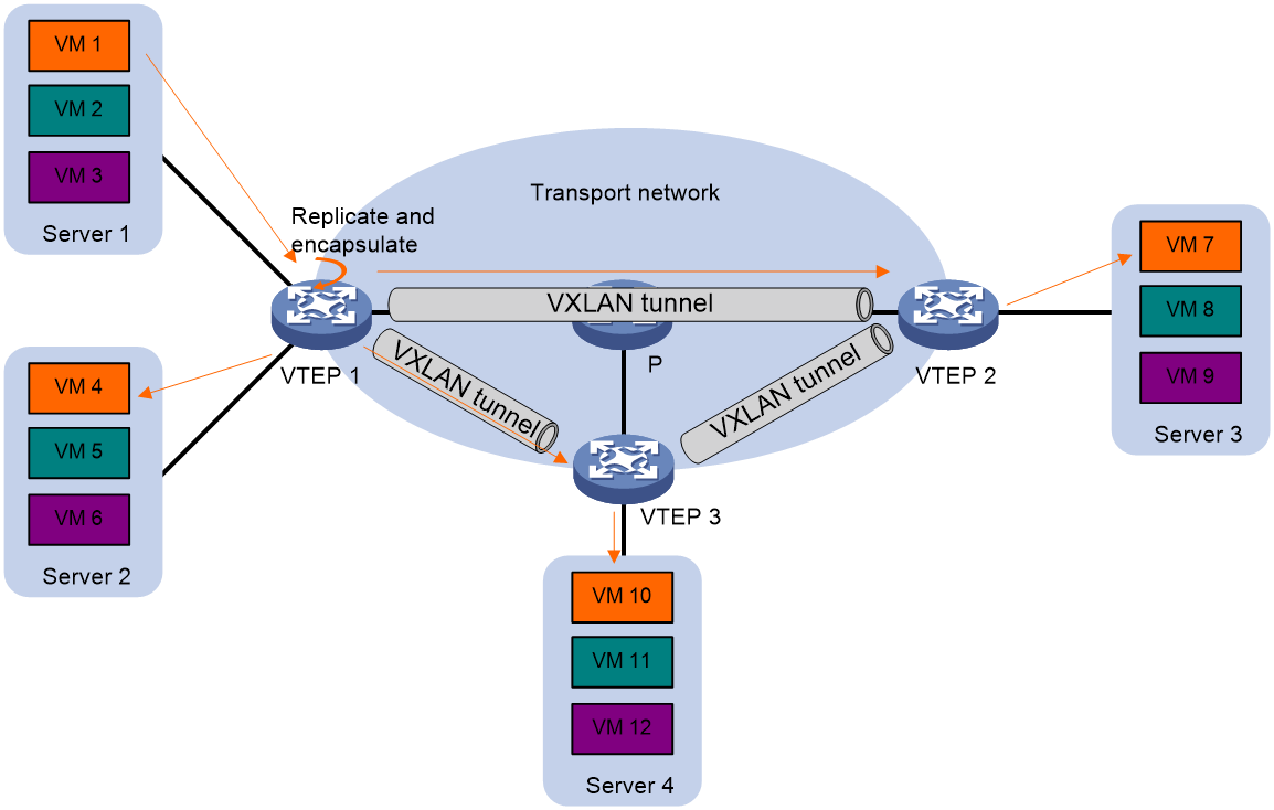
Unicast mode (head-end replication)
As shown in Figure 5, the source VTEP replicates the flood frame, and then sends one replica to the destination IP address of each VXLAN tunnel in the VXLAN.
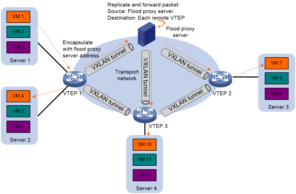
Flood proxy mode (proxy server replication)
As shown in Figure 6, the source VTEP sends the flood frame in a VXLAN packet over a VXLAN tunnel to a flood proxy server. The flood proxy server replicates and forwards the packet to each remote VTEP through its VXLAN tunnels.
The flood proxy mode applies to VXLANs that have many sites. This mode reduces flood traffic in the transport network without using a multicast protocol. To use a flood proxy server, you must set up a VXLAN tunnel to the server on each VTEP.
The flood proxy mode is typically used in SDN transport networks that have a virtual server as the flood proxy server. For VTEPs to forward packets based on the MAC address table issued by an SDN controller, you must perform the following tasks on the VTEPs:
· Disable remote-MAC address learning by using the vxlan tunnel mac-learning disable command.
· Disable source MAC check on all transport-facing interfaces by using the undo mac-address static source-check enable command. If the VTEP is an IRF fabric, you must also disable the feature on all IRF ports.
Access modes of VSIs
The access mode of a VSI determines how the VTEP processes the 802.1Q VLAN tags in the Ethernet frames.
VLAN access mode
In this mode, Ethernet frames received from or sent to the local site must contain 802.1Q VLAN tags.
· For an Ethernet frame received from the local site, the VTEP removes all its 802.1Q VLAN tags before forwarding the frame.
· For an Ethernet frame destined for the local site, the VTEP adds 802.1Q VLAN tags to the frame before forwarding the frame.
In VLAN access mode, VXLAN packets sent between sites do not contain 802.1Q VLAN tags. You can use different 802.1Q VLANs to provide the same service in different sites.
Ethernet access mode
The VTEP does not process the 802.1Q VLAN tags of Ethernet frames received from or sent to the local site.
· For an Ethernet frame received from the local site, the VTEP forwards the frame with the 802.1Q VLAN tags intact.
· For an Ethernet frame destined for the local site, the VTEP forwards the frame without adding 802.1Q VLAN tags.
In Ethernet access mode, VXLAN packets sent between VXLAN sites contain 802.1Q VLAN tags. You must use the same VLAN to provide the same service between sites.
ARP flood suppression
ARP flood suppression reduces ARP request broadcasts by enabling the VTEP to reply to ARP requests on behalf of VMs.
As shown in Figure 7, this feature snoops ARP packets to populate the ARP flood suppression table with local and remote MAC addresses. If an ARP request has a matching entry, the VTEP replies to the request on behalf of the VM. If no match is found, the VTEP floods the request to both local and remote sites.
Figure 7 ARP flood suppression
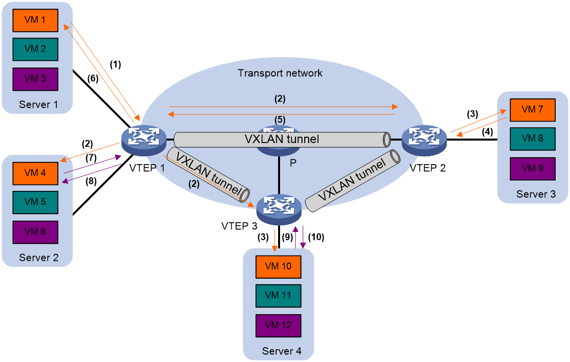
ARP flood suppression uses the following workflow:
1. VM 1 sends an ARP request to obtain the MAC address of VM 7.
2. VTEP 1 creates a suppression entry for VM 1, and floods the ARP request in the VXLAN.
3. VTEP 2 and VTEP 3 de-encapsulate the ARP request. The VTEPs create a suppression entry for VM 1, and broadcast the request in the local site.
4. VM 7 sends an ARP reply.
5. VTEP 2 creates a suppression entry for VM 7 and forwards the ARP reply to VTEP 1.
6. VTEP 1 de-encapsulates the ARP reply, creates a suppression entry for VM 7, and forwards the ARP reply to VM 1.
7. VM 4 sends an ARP request to obtain the MAC address of VM 1 or VM 7.
8. VTEP 1 creates a suppression entry for VM 4 and replies to the ARP request.
9. VM 10 sends an ARP request to obtain the MAC address of VM 1.
10. VTEP 3 creates a suppression entry for VM 10 and replies to the ARP request.
VXLAN IP gateways
A VXLAN IP gateway provides Layer 3 forwarding services for VMs in VXLANs. A VXLAN IP gateway can be an independent device or be collocated with a VTEP. For more information about VXLAN IP gateway placement, see "Configuring VXLAN IP gateways."
Protocols and standards
RFC 7348, Virtual eXtensible Local Area Network (VXLAN): A Framework for Overlaying Virtualized Layer 2 Networks over Layer 3 Networks
Configuring basic VXLAN features
VXLAN tasks at a glance
To configure basic VXLAN settings, perform the following tasks on VTEPs:
3. Manually assigning VXLAN tunnels to a VXLAN
4. Assigning customer frames to a VSI
5. (Optional.) Managing MAC address entries
¡ Configuring static remote-MAC address entries
¡ Disabling remote-MAC address learning
6. (Optional.) Configuring VXLAN packet parameters
¡ Setting the destination UDP port number of VXLAN packets
¡ Setting the source UDP port number of VXLAN packets
¡ Configuring VXLAN packet check
7. (Optional.) Reducing flood traffic in the transport network
¡ Confining unknown-unicast floods to the local site
¡ Enabling ARP flood suppression
8. (Optional.) Enabling VXLAN packet statistics
9. (Optional.) Enabling VXLAN fast forwarding
Prerequisites for VXLAN
Configure a routing protocol on the devices in the transport network to make sure the VTEPs can reach one another.
Creating a VXLAN on a VSI
1. Enter system view.
system-view
2. Enable L2VPN.
l2vpn enable
By default, L2VPN is disabled.
3. Create a VSI and enter VSI view.
vsi vsi-name
4. Enable the VSI.
undo shutdown
By default, a VSI is enabled.
5. Create a VXLAN and enter VXLAN view.
vxlan vxlan-id
You can create only one VXLAN on a VSI.
The VXLAN ID must be unique for each VSI.
6. (Optional.) Configure VSI parameters:
a. Return to VSI view.
quit
b. Configure a VSI description.
description text
By default, a VSI does not have a description.
c. Set the MTU for the VSI.
mtu mtu
The default MTU for a VSI is 1500 bytes.
The MTU set by using this command limits the maximum length of the packets that a VSI receives from ACs and forwards through VXLAN tunnels. The MTU does not limit the maximum length of other packets in the VXLAN VSI.
d. Enable MAC address learning for the VSI.
mac-learning enable
By default, MAC address learning is enabled for a VSI.
Configuring a VXLAN tunnel
Manually creating a VXLAN tunnel
About this task
When you manually create a VXLAN tunnel, specify addresses on the local VTEP and the remote VTEP as the tunnel source and destination addresses, respectively.
Restrictions and guidelines
As a best practice, do not configure multiple VXLAN tunnels to use the same source and destination IP addresses.
Make sure the following VXLAN tunnels are not associated with the same VXLAN when they have the same tunnel destination IP address:
· A VXLAN tunnel automatically created by EVPN.
· A manually created VXLAN tunnel.
For more information about EVPN, see EVPN Configuration Guide.
This task provides basic VXLAN tunnel configuration. For more information about tunnel configuration and commands, see Layer 3—IP Services Configuration Guide and Layer 3—IP Services Command Reference.
Procedure
1. Enter system view.
system-view
2. (Optional.) Specify a global source IP address for VXLAN tunnels.
tunnel global source-address { ipv4-address | ipv6 ipv6-address }
By default, no global source IP address is specified for VXLAN tunnels.
A VXLAN tunnel uses the global source address if you do not specify a source interface or source address for the tunnel.
3. Create a VXLAN tunnel interface and enter tunnel interface view.
interface tunnel tunnel-number mode vxlan [ ipv6 ]
The endpoints of a tunnel must use the same tunnel mode.
4. Specify a source address for the tunnel. Choose one of the following methods:
¡ Specify a source IP address for the tunnel.
source { ipv4-address | ipv6-address }
The specified IP address is used in the outer IP header of tunneled VXLAN packets.
¡ Specify a source interface for the tunnel.
source interface-type interface-number
The primary IP address of the specified interface is used in the outer IP header of tunneled VXLAN packets.
By default, no source IP address or source interface is specified for a tunnel.
Do not perform this step if you are using OVSDB for VXLAN tunnel management.
5. Specify a destination IP address for the tunnel.
destination { ipv4-address | ipv6-address }
By default, no destination IP address is specified for a tunnel.
Specify the remote VTEP's IP address. This IP address will be the destination IP address in the outer IP header of tunneled VXLAN packets.
Enabling BFD on a VXLAN tunnel
About this task
Enable BFD on both ends of a VXLAN tunnel for quick link connectivity detection. The VTEPs periodically send BFD single-hop control packets to each other through the VXLAN tunnel. A VTEP sets the tunnel state to Defect if it has not received control packets from the remote end for 5 seconds. In this situation, the tunnel interface state is still Up. The tunnel state will change from Defect to Up if the VTEP can receive BFD control packets again.
Restrictions and guidelines
You must enable BFD on both ends of a VXLAN tunnel.
Procedure
1. Enter system view.
system-view
2. Specify the reserved VXLAN.
reserved vxlan vxlan-id
By default, no VXLAN has been reserved.
For BFD sessions to come up, you must reserve a VXLAN.
You can specify only one reserved VXLAN on the VTEP. The reserved VXLAN cannot be the VXLAN created on any VSI.
The reserved VXLAN ID cannot be the same as any remote VXLAN ID specified by using the mapping vni command. For more information about the mapping vni command, see EVPN Command Reference.
3. Enter VXLAN tunnel interface view.
interface tunnel tunnel-number
4. Enable BFD on the tunnel.
tunnel bfd enable destination-mac mac-address
By default, BFD is disabled on a tunnel.
Manually assigning VXLAN tunnels to a VXLAN
About this task
To provide Layer 2 connectivity for a VXLAN between two sites, you must assign the VXLAN tunnel between the sites to the VXLAN.
You can assign multiple VXLAN tunnels to a VXLAN, and configure a VXLAN tunnel to trunk multiple VXLANs. For a unicast-mode VXLAN, the system floods unknown unicast, multicast, and broadcast traffic to each tunnel associated with the VXLAN. If a flood proxy server is used, the VTEP sends flood traffic to the server through the flood proxy tunnel. The flood proxy server replicates and forwards flood traffic to remote VTEPs.
Restrictions and guidelines
For full Layer 2 connectivity in the VXLAN, make sure the VXLAN contains the VXLAN tunnel between each pair of sites in the VXLAN.
If you disable split horizon on a VXLAN tunnel, make sure the corresponding VXLAN does not have another VXLAN tunnel that is destined for the same remote VTEP.
Procedure
1. Enter system view.
system-view
2. Enter VSI view.
vsi vsi-name
3. Enter VXLAN view.
vxlan vxlan-id
4. Assign VXLAN tunnels to the VXLAN.
tunnel tunnel-number [ flooding-proxy | no-split-horizon ] *
By default, a VXLAN does not contain any VXLAN tunnels.
|
Parameter |
Description |
|
flooding-proxy |
Enables flood proxy on a tunnel for it to send flood traffic to the flood proxy server. The flood proxy server replicates and forwards flood traffic to remote VTEPs. |
|
no-split-horizon |
Disables split horizon on the tunnel. The tunnel can forward the traffic that is received on ACs and other VXLAN tunnels. |
Assigning customer frames to a VSI
About this task
To assign the customer traffic on a Layer 3 interface to a VXLAN, map the interface to the VXLAN's VSI. The VSI uses its MAC address table to forward the customer traffic.
Procedure
1. Enter system view.
system-view
2. Enter Layer 3 interface view.
interface interface-type interface-number
3. Configure the VLAN tag processing rule for incoming traffic.
l2vpn rewrite inbound tag { nest { c-vid vlan-id | s-vid vlan-id [ c-vid vlan-id ] } | remark 1-to-2 s-vid vlan-id c-vid vlan-id } [ symmetric ]
By default, VLAN tags of incoming traffic are not processed.
4. Map the Layer 3 interface to a VSI.
xconnect vsi vsi-name [ access-mode { ethernet | vlan } ] [ track track-entry-number&<1-3> ]
By default, a Layer 3 interface is not mapped to any VSI.
If the AC is a Layer 3 subinterface, you can specify the access mode. The default access mode is VLAN. If the AC is a Layer 3 interface, you cannot specify the access mode.
Managing MAC address entries
About MAC address entry management
Local-MAC address entries are only learned dynamically. You can log local MAC addresses and local-MAC changes.
Remote-MAC address entries have a variety of types, including manually added entries and dynamically learned entries.
Configuring static remote-MAC address entries
Restrictions and guidelines
Do not configure static remote-MAC entries for VXLAN tunnels that are automatically established by using EVPN.
· EVPN re-establishes VXLAN tunnels if the transport-facing interface goes down and then comes up. If you have configured static remote-MAC entries, the entries are deleted when the tunnels are re-established.
· EVPN re-establishes VXLAN tunnels if you perform configuration rollback. If the tunnel IDs change during tunnel re-establishment, configuration rollback fails, and static remote-MAC entries on the tunnels cannot be restored.
For more information about EVPN, see EVPN Configuration Guide.
Procedure
1. Enter system view.
system-view
2. Add a static remote-MAC address entry.
mac-address static mac-address interface tunnel tunnel-number vsi vsi-name
For the setting to take effect, make sure the VSI's VXLAN has been specified on the VXLAN tunnel.
Disabling remote-MAC address learning
About this task
When network attacks occur, disable remote-MAC address learning to prevent the device from learning incorrect remote MAC addresses. You can manually add static remote-MAC address entries.
Procedure
1. Enter system view.
system-view
2. Disable remote-MAC address learning.
vxlan tunnel mac-learning disable
By default, remote-MAC address learning is enabled.
Enabling local-MAC logging
About this task
When the local-MAC logging feature is enabled, the VXLAN module immediately sends a log message with its local MAC addresses to the information center. When a local MAC address is added or removed, a log message is also sent to the information center to notify the local-MAC change.
With the information center, you can set log message filtering and output rules, including output destinations. For more information about configuring the information center, see Network Management and Monitoring Configuration Guide.
Procedure
1. Enter system view.
system-view
2. Enable local-MAC logging.
vxlan local-mac report
By default, local-MAC logging is disabled.
Setting the destination UDP port number of VXLAN packets
1. Enter system view.
system-view
2. Set a destination UDP port for VXLAN packets.
vxlan udp-port port-number
By default, the destination UDP port number is 4789 for VXLAN packets.
You must configure the same destination UDP port number on all VTEPs in a VXLAN.
Setting the source UDP port number of VXLAN packets
About this task
Perform this task to enable a VXLAN tunnel interface to encapsulate different source UDP port numbers for traffic flows. This allows IPsec to identify the VXLAN packets to encrypt by the source UDP port number in the VXLAN encapsulation.
Restrictions and guidelines
The commands used for setting the source UDP port number of VXLAN packets take effect only on IPv4-based VXLAN. Only manually created VXLAN tunnel interfaces support these commands.
The vxlan source udp-port acl command has a higher priority than the vxlan source udp-port five-tuple command. If you use both commands on a VXLAN tunnel interface, the vxlan source udp-port five-tuple command takes effect only on the frames that fail to match the ACL specified by using the vxlan source udp-port acl command.
Procedure
1. Enter system view.
system-view
2. Enter tunnel interface view.
¡ Enter VXLAN tunnel interface view.
interface tunnel tunnel-number mode vxlan [ ipv6 ]
¡ Enter VXLAN-DCI tunnel interface view.
interface tunnel tunnel-number mode vxlan-dci [ ipv6 ]
3. Set a source UDP port for VXLAN packets.
¡ Configure an ACL match criterion and specify the source UDP port number in the VXLAN encapsulation for matching frames.
vxlan source udp-port port-number acl acl-number
If you execute this command multiple times, the most recent configuration takes effect.
If the ACL specified by using this command does not exist or does not contain an IP address-related rule, frames are encapsulated based on the default setting.
¡ Generate the source UDP port number in the VXLAN encapsulation based on the IP five-tuple of the inner Ethernet frame.
vxlan source udp-port five-tuple
By default, the source UDP port number in the VXLAN encapsulation is generated based on the source and destination MAC addresses of the inner Ethernet frame.
Configuring VXLAN packet check
About this task
The device can check the UDP checksum and 802.1Q VLAN tags of each received VXLAN packet.
· UDP checksum check—The device always sets the UDP checksum of VXLAN packets to zero. For compatibility with third-party devices, a VXLAN packet can pass the check if its UDP checksum is zero or correct. If its UDP checksum is incorrect, the VXLAN packet fails the check and is dropped.
· VLAN tag check—The device checks the inner Ethernet header of each VXLAN packet for 802.1Q VLAN tags. If the header contains 802.1Q VLAN tags, the device drops the packet.
Procedure
1. Enter system view.
system-view
2. Enable the VTEP to drop VXLAN packets that fail UDP checksum check.
vxlan invalid-udp-checksum discard
By default, the VTEP does not check the UDP checksum of VXLAN packets.
Confining unknown-unicast floods to the local site
About this task
By default, the VTEP floods unknown unicast frames received from the local site to the following interfaces in the frame's VXLAN:
· All site-facing interfaces except for the incoming interface.
· All VXLAN tunnel interfaces.
To exclude a remote MAC address from the flood suppression done by using this feature, enable selective flood for the MAC address. The VTEP will flood the frames destined for the MAC address to remote sites.
Procedure
1. Enter system view.
system-view
2. Enter VSI view.
vsi vsi-name
3. Disable the VSI to flood unknown unicast traffic to VXLAN tunnel interfaces.
flooding disable
By default, unknown unicast traffic is flooded to all interfaces in the VXLAN, except for the incoming interface.
4. (Optional.) Enable selective flood for a MAC address.
selective-flooding mac-address mac-address
Enabling ARP flood suppression
Restrictions and guidelines
The aging timer is fixed at 25 minutes for ARP flood suppression entries. If the suppression table is full, the VTEP stops learning new entries. For the VTEP to learn new entries, you must wait for old entries to age out, or use the reset arp suppression vsi command to clear the table.
If the flooding disable command is configured, set the MAC aging timer to a higher value than the aging timer for ARP flood suppression entries on all VTEPs. This setting prevents the traffic blackhole that occurs when a MAC address entry ages out before its ARP flood suppression entry ages out. To set the MAC aging timer, use the mac-address timer command.
When remote ARP learning is disabled for VXLANs, the device does not use ARP flood suppression entries to respond to ARP requests received on VXLAN tunnels.
Procedure
1. Enter system view.
system-view
2. Enter VSI view.
vsi vsi-name
3. Enable ARP flood suppression.
arp suppression enable
By default, ARP flood suppression is disabled.
Enabling VXLAN packet statistics
Enabling packet statistics for a VSI
Restrictions and guidelines
To display the packet statistics for a VSI, use the display l2vpn vsi verbose command in any view.
To clear the packet statistics for a VSI, use the reset l2vpn statistics vsi command in user view.
Procedure
1. Enter system view.
system-view
2. Enter VSI view.
vsi vsi-name
3. Enable packet statistics for the VSI.
statistics enable
By default, the packet statistics feature is disabled for all VSIs.
Enable packet statistics for all VXLAN tunnels of a VSI
About this task
VXLAN tunnels can be manually or automatically created. You can enable packet statistics for all VXLAN tunnels of a VSI.
If you enable packet statistics in VSI view, follow these guidelines:
· To display the packet statistics for VXLAN tunnels, use the display vxlan tunnel command in any view.
· To clear the packet statistics for VXLAN tunnels, use the reset l2vpn statistics tunnel command in user view.
Procedure
1. Enter system view.
system-view
2. Enter VSI view.
vsi vsi-name
3. Enable packet statistics for all VXLAN tunnels associated with the VSI.
tunnel statistics enable
By default, the packet statistics feature is disabled for the VXLAN tunnels associated with a VSI.
This command enables packet statistics only for VXLAN tunnels. It does not take effect on VXLAN-DCI tunnels.
Enabling VXLAN fast forwarding
About this task
VXLAN fast forwarding enables the device to bypass QoS and security services when the device forwards data traffic over VXLAN tunnels based on the software. As a best practice, enable this feature to improve forwarding speed only when QoS and security services are not configured on the following interfaces:
· VSI interfaces.
· VSI subinterfaces.
· Traffic outgoing interfaces for VXLAN tunnels.
Restrictions and guidelines
When VXLAN fast forwarding is enabled, a VXLAN tunnel cannot use ECMP routes to load share traffic. Instead, it selects one route from the ECMP routes to forward VXLAN packets.
Procedure
1. Enter system view.
system-view
2. Enable VXLAN fast forwarding.
vxlan fast-forwarding enable
By default, VXLAN fast forwarding is disabled.
Display and maintenance commands for VXLANs
Execute display commands in any view and reset commands in user view.
|
Task |
Command |
|
Display ARP flood suppression entries on VSIs. |
In standalone mode: display arp suppression vsi [ name vsi-name ] [ count ] In IRF mode: display arp suppression vsi [ name vsi-name ] [ slot slot-number ] [ count ] |
|
Display information about tunnel interfaces. |
display interface [ tunnel [ number ] ] [ brief [ description | down ] ] |
|
Display L2VPN information for Layer 3 interfaces that are mapped to VSIs. |
display l2vpn interface [ vsi vsi-name | interface-type interface-number ] [ verbose ] |
|
Display MAC address entries for VSIs. |
display l2vpn mac-address [ vsi vsi-name ] [ dynamic ] [ count ] |
|
Display information about VSIs. |
display l2vpn vsi [ name vsi-name ] [ verbose ] |
|
Display VXLAN tunnel information for VXLANs. |
display vxlan tunnel [ vxlan vxlan-id [ tunnel tunnel-number ] ] |
|
Clear ARP flood suppression entries on VSIs. |
reset arp suppression vsi [ name vsi-name ] |
|
Clear dynamic MAC address entries on VSIs. |
reset l2vpn mac-address [ vsi vsi-name ] |
|
Clear packet statistics on VXLAN tunnel interfaces. |
reset l2vpn statistics tunnel [ vsi vsi-name ] |
|
Clear packet statistics on VSIs. |
reset l2vpn statistics vsi [ name vsi-name ] |
|
|
NOTE: For more information about the display interface tunnel command, see tunneling commands in Layer 3—IP Services Command Reference. |
VXLAN configuration examples
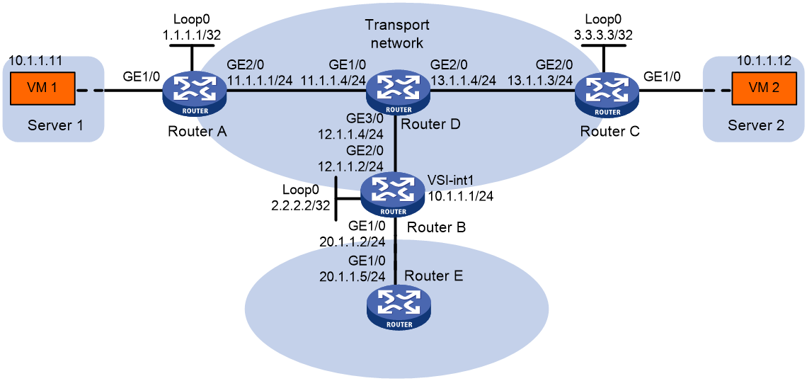
Example: Configuring a unicast-mode VXLAN
Network configuration
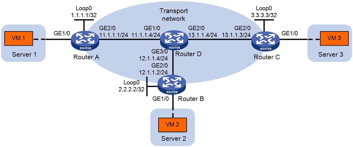
As shown in Figure 8:
· Configure VXLAN 10 as a unicast-mode VXLAN on Router A, Router B, and Router C to provide Layer 2 connectivity for the VMs across the network sites.
· Manually establish VXLAN tunnels and assign the tunnels to VXLAN 10.
· Enable remote-MAC address learning.
Procedure
1. Configure IP addresses and unicast routing settings:
# Assign IP addresses to interfaces, as shown in Figure 8. (Details not shown.)
# Configure OSPF on all transport network routers (Routers A through D). (Details not shown.)
2. Configure Router A:
# Enable L2VPN.
<RouterA> system-view
[RouterA] l2vpn enable
# Create VSI vpna and VXLAN 10.
[RouterA] vsi vpna
[RouterA-vsi-vpna] vxlan 10
[RouterA-vsi-vpna-vxlan-10] quit
[RouterA-vsi-vpna] quit
# Assign an IP address to Loopback 0. The IP address will be used as the source IP address of the VXLAN tunnels to Router B and Router C.
[RouterA] interface loopback 0
[RouterA-Loopback0] ip address 1.1.1.1 255.255.255.255
[RouterA-Loopback0] quit
# Create a VXLAN tunnel to Router B. The tunnel interface name is Tunnel 1.
[RouterA] interface tunnel 1 mode vxlan
[RouterA-Tunnel1] source 1.1.1.1
[RouterA-Tunnel1] destination 2.2.2.2
[RouterA-Tunnel1] quit
# Create a VXLAN tunnel to Router C. The tunnel interface name is Tunnel 2.
[RouterA] interface tunnel 2 mode vxlan
[RouterA-Tunnel2] source 1.1.1.1
[RouterA-Tunnel2] destination 3.3.3.3
[RouterA-Tunnel2] quit
# Assign Tunnel 1 and Tunnel 2 to VXLAN 10.
[RouterA] vsi vpna
[RouterA-vsi-vpna] vxlan 10
[RouterA-vsi-vpna-vxlan-10] tunnel 1
[RouterA-vsi-vpna-vxlan-10] tunnel 2
[RouterA-vsi-vpna-vxlan-10] quit
[RouterA-vsi-vpna] quit
# Map GigabitEthernet 1/0 to VSI vpna.
[RouterA] interface gigabitethernet 1/0
[RouterA-GigabitEthernet1/0] xconnect vsi vpna
[RouterA-GigabitEthernet1/0] quit
3. Configure Router B:
# Enable L2VPN.
<RouterB> system-view
[RouterB] l2vpn enable
# Create VSI vpna and VXLAN 10.
[RouterB] vsi vpna
[RouterB-vsi-vpna] vxlan 10
[RouterB-vsi-vpna-vxlan-10] quit
[RouterB-vsi-vpna] quit
# Assign an IP address to Loopback 0. The IP address will be used as the source IP address of the VXLAN tunnels to Router A and Router C.
[RouterB] interface loopback 0
[RouterB-Loopback0] ip address 2.2.2.2 255.255.255.255
[RouterB-Loopback0] quit
# Create a VXLAN tunnel to Router A. The tunnel interface name is Tunnel 2.
[RouterB] interface tunnel 2 mode vxlan
[RouterB-Tunnel2] source 2.2.2.2
[RouterB-Tunnel2] destination 1.1.1.1
[RouterB-Tunnel2] quit
# Create a VXLAN tunnel to Router C. The tunnel interface name is Tunnel 3.
[RouterB] interface tunnel 3 mode vxlan
[RouterB-Tunnel3] source 2.2.2.2
[RouterB-Tunnel3] destination 3.3.3.3
[RouterB-Tunnel3] quit
# Assign Tunnel 2 and Tunnel 3 to VXLAN 10.
[RouterB] vsi vpna
[RouterB-vsi-vpna] vxlan 10
[RouterB-vsi-vpna-vxlan-10] tunnel 2
[RouterB-vsi-vpna-vxlan-10] tunnel 3
[RouterB-vsi-vpna-vxlan-10] quit
[RouterB-vsi-vpna] quit
# Map GigabitEthernet 1/0 to VSI vpna.
[RouterB] interface gigabitethernet 1/0
[RouterB-GigabitEthernet1/0] xconnect vsi vpna
[RouterB-GigabitEthernet1/0] quit
4. Configure Router C:
# Enable L2VPN.
<RouterC> system-view
[RouterC] l2vpn enable
# Create VSI vpna and VXLAN 10.
[RouterC] vsi vpna
[RouterC-vsi-vpna] vxlan 10
[RouterC-vsi-vpna-vxlan-10] quit
[RouterC-vsi-vpna] quit
# Assign an IP address to Loopback 0. The IP address will be used as the source IP address of the VXLAN tunnels to Router A and Router B.
[RouterC] interface loopback 0
[RouterC-Loopback0] ip address 3.3.3.3 255.255.255.255
[RouterC-Loopback0] quit
# Create a VXLAN tunnel to Router A. The tunnel interface name is Tunnel 1.
[RouterC] interface tunnel 1 mode vxlan
[RouterC-Tunnel1] source 3.3.3.3
[RouterC-Tunnel1] destination 1.1.1.1
[RouterC-Tunnel1] quit
# Create a VXLAN tunnel to Router B. The tunnel interface name is Tunnel 3.
[RouterC] interface tunnel 3 mode vxlan
[RouterC-Tunnel3] source 3.3.3.3
[RouterC-Tunnel3] destination 2.2.2.2
[RouterC-Tunnel3] quit
# Assign Tunnel 1 and Tunnel 3 to VXLAN 10.
[RouterC] vsi vpna
[RouterC-vsi-vpna] vxlan 10
[RouterC-vsi-vpna-vxlan-10] tunnel 1
[RouterC-vsi-vpna-vxlan-10] tunnel 3
[RouterC-vsi-vpna-vxlan-10] quit
[RouterC-vsi-vpna] quit
# Map GigabitEthernet 1/0 to VSI vpna.
[RouterC] interface gigabitethernet 1/0
[RouterC-GigabitEthernet1/0] xconnect vsi vpna
[RouterC-GigabitEthernet1/0] quit
Verifying the configuration
1. Verify the VXLAN settings on the VTEPs. This example uses Router A.
# Verify that the VXLAN tunnel interfaces on the VTEP are up.
[RouterA] display interface tunnel 1
Tunnel1
Current state: UP
Line protocol state: UP
Description: Tunnel1 Interface
Bandwidth: 64 kbps
Maximum transmission unit: 64000
Internet protocol processing: Disabled
Output queue - Urgent queuing: Size/Length/Discards 0/100/0
Output queue - Protocol queuing: Size/Length/Discards 0/500/0
Output queue - FIFO queuing: Size/Length/Discards 0/75/0
Last clearing of counters: Never
Tunnel source 1.1.1.1, destination 2.2.2.2
Tunnel protocol/transport UDP_VXLAN/IP
Last 300 seconds input rate: 0 bytes/sec, 0 bits/sec, 0 packets/sec
Last 300 seconds output rate: 0 bytes/sec, 0 bits/sec, 0 packets/sec
Input: 0 packets, 0 bytes, 0 drops
Output: 0 packets, 0 bytes, 0 drops
# Verify that the VXLAN tunnels have been assigned to the VXLAN.
[RouterA] display l2vpn vsi verbose
VSI Name: vpna
VSI Index : 0
VSI State : Up
MTU : 1500
Bandwidth : -
Broadcast Restrain : -
Multicast Restrain : -
Unknown Unicast Restrain: -
MAC Learning : Enabled
MAC Table Limit : -
MAC Learning rate : -
Drop Unknown : -
PW Redundancy : Slave
Flooding : Enabled
Service Class : -
Statistics : Disabled
VXLAN ID : 10
Tunnel Statistics : Disabled
Tunnels:
Tunnel Name Link ID State Type Flood Proxy Split horizon
Tunnel1 0x5000001 Up Manual Disabled Enabled
Tunnel2 0x5000002 Up Manual Disabled Enabled
ACs:
AC Link ID State
GE1/0 0 Up
# Verify that the VTEP has learned the MAC addresses of remote VMs.
<RouterA> display l2vpn mac-address
MAC Address State VSI Name Link ID/Name Aging
cc3e-5f9c-6cdb Dynamic vpna Tunnel1 Aging
cc3e-5f9c-23dc Dynamic vpna Tunnel2 Aging
--- 2 mac address(es) found ---
2. Verify that VM 1, VM 2, and VM 3 can ping each other. (Details not shown.)
Configuring VXLAN IP gateways
About VXLAN IP gateways
The following are available IP gateway placement designs for VXLANs:
· VXLAN IP gateways separated from VTEPs—Use a VXLAN-unaware device as a gateway to the external network for VXLANs. On the gateway, you do not need to configure VXLAN settings.
· VXLAN IP gateways collocated with VTEPs—Include the following placement designs:
¡ Centralized VXLAN IP gateway deployment—Use one VTEP to provide Layer 3 forwarding for VXLANs. Typically, the gateway-collocated VTEP connects to other VTEPs and the external network. To use this design, make sure the IP gateway has sufficient bandwidth and processing capability. Centralized VXLAN IP gateways provide services only for IPv4 networks.
¡ Centralized VXLAN gateway group deployment—Use one VTEP group that contains redundant centralized VXLAN IP gateways to provide reliable gateway services for VXLANs.
¡ Distributed VXLAN IP gateway deployment—Deploy one VXLAN IP gateway on each VTEP to provide Layer 3 forwarding for VXLANs at their respective sites. This design distributes the Layer 3 traffic load across VTEPs. However, its configuration is more complex than the centralized VXLAN IP gateway design. Distributed gateways can provide services for both IPv4 and IPv6 networks.
In a collocation design, the VTEPs use virtual Layer 3 VSI interfaces as gateway interfaces to provide services for VXLANs.
|
|
NOTE: The following information describes traffic forwarding of VXLAN IP gateways in IPv4 networks. Traffic forwarding of VXLAN IP gateways in IPv6 networks is similar to that in IPv4 networks. |
VXLAN IP gateways separated from VTEPs
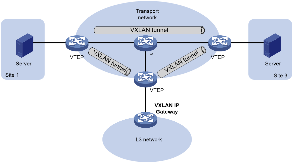
As shown in Figure 9, an independent VXLAN IP gateway connects a Layer 3 network to a VTEP. VMs send Layer 3 traffic in Layer 2 frames to the gateway through VXLAN tunnels. When the tunneled VXLAN packets arrive, the VTEP terminates the VXLANs and forwards the inner frames to the gateway. In this gateway placement design, the VTEP does not perform Layer 3 forwarding for VXLANs.
Figure 9 VXLAN IP gateway separated from VTEPs
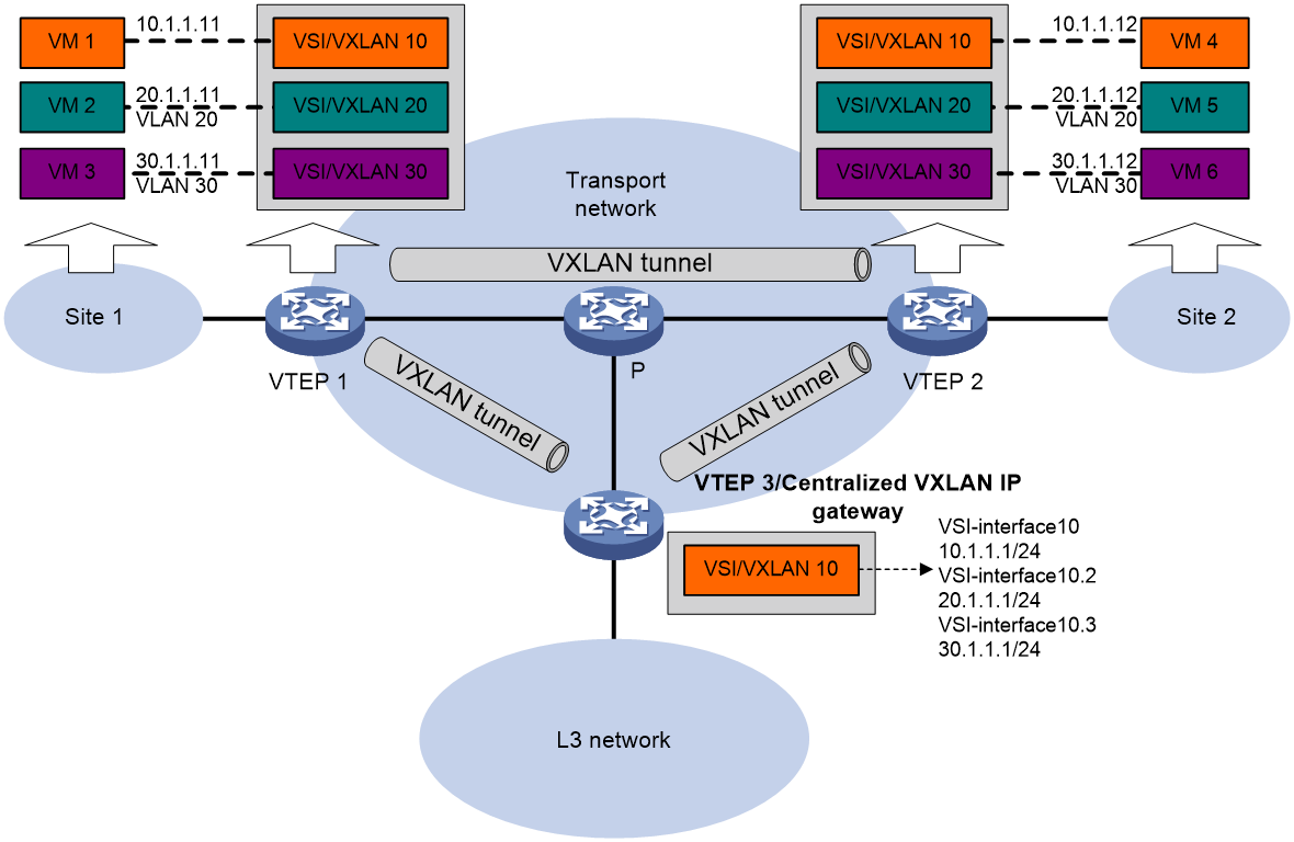
Centralized VXLAN IP gateway deployment
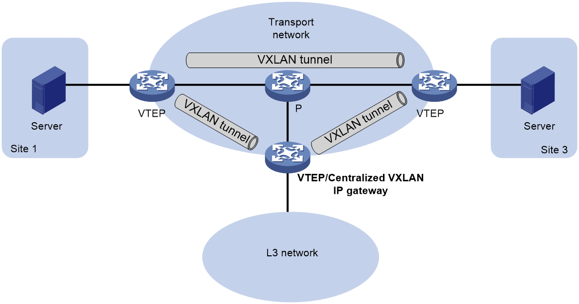
As shown in Figure 10, a VTEP acts as a gateway for VMs in the VXLANs. The VTEP both terminates the VXLANs and performs Layer 3 forwarding for the VMs.
Figure 10 Centralized VXLAN IP gateway placement design
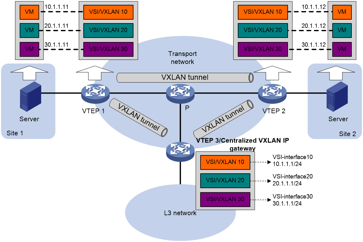
As shown in Figure 11, the network uses the following process to forward Layer 3 traffic from VM 10.1.1.11 to the Layer 3 network:
1. The VM sends an ARP request to obtain the MAC address of the gateway (VTEP 3) at 10.1.1.1.
2. VTEP 1 floods the ARP request to all remote VTEPs.
3. VTEP 3 de-encapsulates the ARP request, creates an ARP entry for the VM, and sends an ARP reply to the VM.
4. VTEP 1 forwards the ARP reply to the VM.
5. The VM learns the MAC address of the gateway, and sends the Layer 3 traffic to the gateway.
6. VTEP 3 removes the VXLAN encapsulation and inner Ethernet header for the traffic, and forwards the traffic to the destination node.
Inter-VXLAN forwarding is the same as this process except for the last step. At the last step of inter-VLAN forwarding, the gateway replaces the source-VXLAN encapsulation with the destination-VXLAN encapsulation, and then forwards the traffic.
Figure 11 Example of centralized VXLAN IP gateway deployment
Centralized VXLAN gateway group deployment
As shown in Figure 12, a VTEP group uses redundant centralized VXLAN IP gateways to provide reliable gateway services for VMs in the VXLANs. All member VTEPs in the group participate in Layer 3 forwarding and load share traffic between the Layer 3 network and the VXLANs. This design distributes processing among multiple VTEPs and prevents single points of failure.
Figure 12 Example of centralized VXLAN IP gateway group deployment
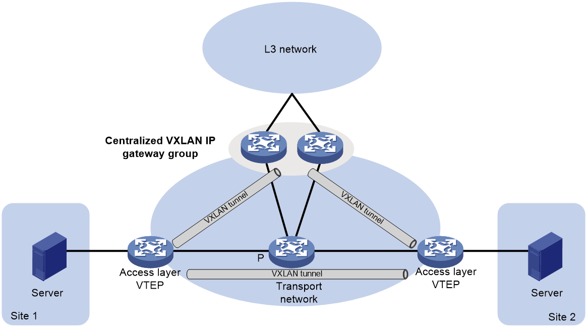
The VTEP group is a virtual gateway that provides services at a group IP address. Access layer VTEPs set up VXLAN tunnels to the group IP address for data traffic forwarding. Each VTEP in the group automatically uses its member IP address to set up tunnels to the other member VTEPs and access layer VTEPs. The tunnels are used to transmit protocol packets and synchronize ARP entries.
Distributed VXLAN IP gateway deployment
About distributed VXLAN IP gateway deployment
As shown in Figure 13, each site's VTEP acts as a gateway to perform Layer 3 forwarding for the VXLANs of the local site. A VTEP acts as a border gateway to the Layer 3 network for the VXLANs.
Figure 13 Distributed VXLAN IP gateway placement design
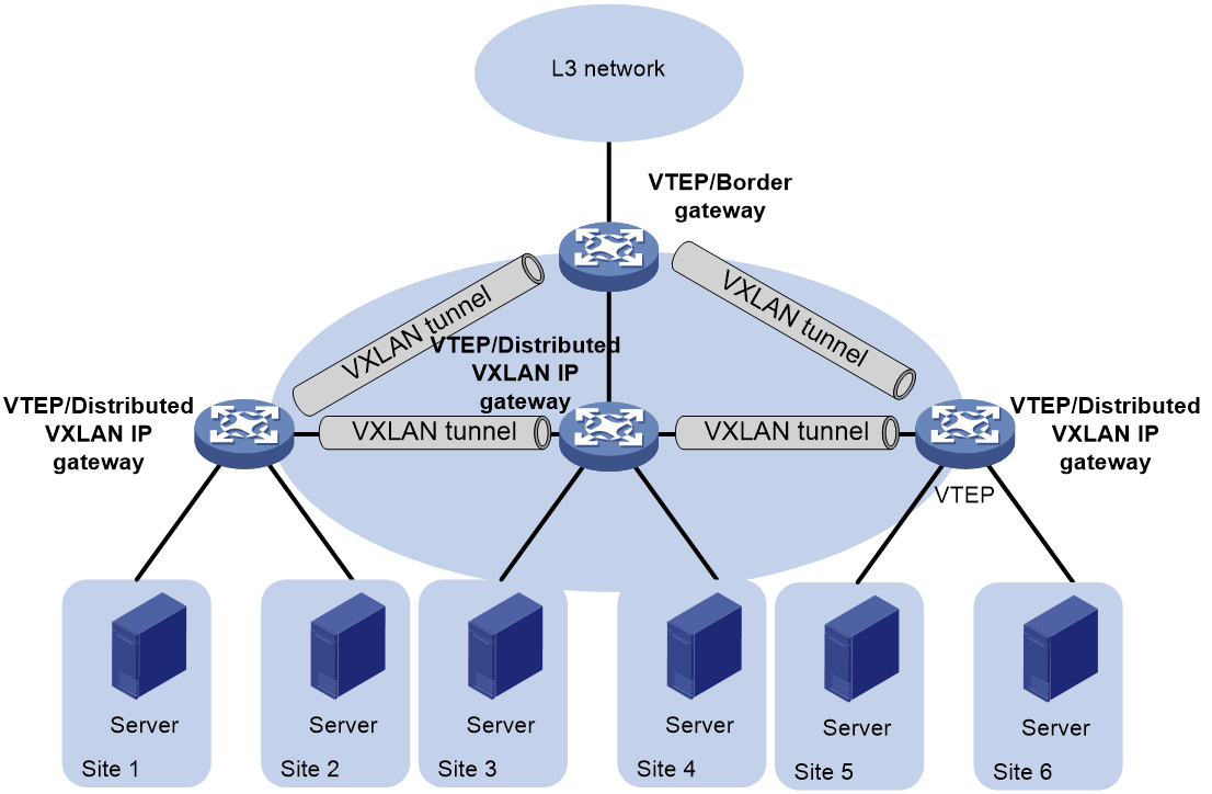
Figure 14 shows an example of distributed VXLAN IP gateway deployment. Create VSI interfaces on each distributed VXLAN IP gateway and the border gateway as gateway interfaces. Assign the same IP address to the same VSI interface on the distributed VXLAN IP gateways. Enable one of the following features on a distributed VXLAN IP gateway:
· ARP flood suppression. The gateway performs Layer 2 forwarding based on MAC address entries and performs Layer 3 forwarding based on ARP entries.
· Local proxy ARP or local ND proxy. The gateway performs Layer 3 forwarding based on ARP or ND entries. The following sections use distributed VXLAN IP gateways enabled with the local proxy ARP or local ND proxy feature to describe the forwarding processes for intra-VXLAN traffic, inter-VXLAN traffic, and traffic from a VXLAN to an external network.
A distributed VXLAN IP gateway can generate ARP or ND entries by a variety of methods. The following sections use dynamically learned ARP or ND entries to describe the forwarding processes.
Figure 14 Example of distributed VXLAN IP gateway deployment
Intra-VXLAN traffic forwarding between sites
As shown in Figure 14, the network uses the following process to forward traffic in a VXLAN between sites (for example, from VM 1 to VM 4 in VXLAN 10):
1. VM 1 sends an ARP request to obtain the MAC address of VM 4.
2. GW 1 performs the following operations:
a. Creates an ARP entry for VM 1 and replies with the MAC address of VSI-interface 10 (the gateway interface for VXLAN 10).
b. Replaces the sender MAC address of the ARP request with the MAC address of VSI-interface 10, and then floods the request to all sites in VXLAN 10.
3. VM 1 creates an ARP entry for VM 4. The MAC address in the entry is the MAC address of VSI-interface 10 on GW 1.
4. GW 2 (the VTEP for VM 4) performs the following operations:
a. De-encapsulates the ARP request and creates an ARP entry for VM 1. The entry contains VM 1's IP address (10.1.1.11), the MAC address of VSI-interface 10 on GW 1, and the incoming tunnel interface.
b. Replaces the sender MAC address of the request with the MAC address of VSI-interface 10 on GW 2, and then floods the request to the local site in VXLAN 10.
5. VM 4 creates an ARP entry for VM 1, and then sends a reply to GW 2. The MAC address in the ARP entry is the MAC address of VSI-interface 10 on GW 2.
6. GW 2 performs the following operations:
a. Creates an ARP entry for VM 4.
b. Replaces the sender MAC address of the reply with the MAC address of VSI-interface 10 on GW 2, and sends the reply to GW 1.
7. GW 1 de-encapsulates the ARP reply and creates an ARP entry for VM 4. The entry contains VM 4's IP address (10.1.1.12), the MAC address of VSI-interface 10 on GW 2, and the incoming tunnel interface.
8. For subsequent traffic between VM 1 and VM 4, GW 1 and GW 2 use their respective ARP tables to make the forwarding decision.
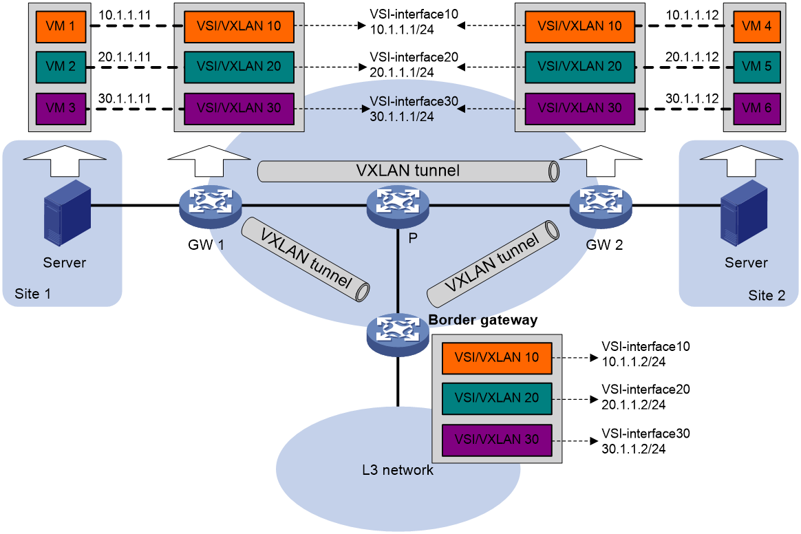
Inter-VXLAN traffic forwarding between sites
As shown in Figure 15, the network uses the following process to forward traffic between VXLANs (for example, from VM 1 in VXLAN 10 to VM 5 in VXLAN 20):
1. VM 1 sends an ARP request to obtain the MAC address of the gateway at 10.1.1.1.
2. GW 1 creates an ARP entry for VM 1 and replies with the MAC address of VSI-interface 10 (the gateway interface for VXLAN 10) so VM 1 will send the packets destined for VM 5 to GW 1.
3. GW 1 sends an ARP request to the local and remote sites in VXLAN 10. In the ARP request, the sender IP address is 10.1.1.11, and the sender MAC address is the MAC address of VSI-interface 10 on GW 1.
4. GW 2 performs the following operations:
a. De-encapsulates the ARP request and creates an ARP entry for VM 1. The entry contains IP address 10.1.1.11 and MAC address of VSI-interface 10 on GW 1, and the incoming tunnel interface.
b. Replaces the sender MAC address of the request with the MAC address of VSI-interface 10 on GW 2, and then floods the request to the local site in VXLAN 10.
c. Sends an ARP reply to GW 1. The reply contains IP address 10.1.1.1 and MAC address of VSI-interface 10 on GW 2).
5. When sending an ARP request in VXLAN 10, GW 1 also sends an ARP request to the local and remote sites in VXLAN 20 to obtain the MAC address of VM 5. In the ARP request, the sender IP address is 20.1.1.1, and the sender MAC address is the MAC address of VSI-interface 20 on GW 1.
6. GW 2 de-encapsulates the ARP request of VXLAN 20, replaces the sender MAC address of the request with the MAC address of VSI-interface 20 on GW 2, and then floods the request to the local site in VXLAN 20.
7. VM 5 creates an ARP entry for GW 2, and then sends a reply to GW 2. The entry contains IP address 20.1.1.1 and MAC address of VSI-interface 20 on GW 2.
8. GW 2 performs the following operations:
a. Creates an ARP entry for VM 5.
b. Sends a gratuitous ARP packet to the local and remote sites. In the packet, the sender IP address is 20.1.1.12, and the sender MAC address is the MAC address of VSI-interface 20 on GW 2.
9. GW 1 de-encapsulates the gratuitous ARP packet and creates an ARP entry for VM 5. The entry contains VM 5's IP address 20.1.1.12, the MAC address of VSI-interface 20 on GW 2, and the incoming tunnel interface.
10. For subsequent traffic between VM 1 and VM 5, GW 1 and GW 2 use their respective ARP tables to make the forwarding decision.
Figure 15 Inter-VXLAN traffic forwarding between sites

VXLAN-to-external network traffic forwarding
As shown in Figure 14, the network uses the following process to forward traffic from a VXLAN to the Layer 3 network (for example, from VM 1 to the host at 50.1.1.1):
1. VM 1 sends an ARP request to obtain the MAC address of the gateway at 10.1.1.1.
2. GW 1 creates an ARP entry for VM 1 and replies with the MAC address of VSI-interface 10 (the gateway interface for VXLAN 10).
3. VM 1 sends a packet destined for the host to GW 1.
4. GW 1 performs the following operations:
a. Searches the IP routing policies or routing table for the next hop. In this example, the next hop for the packet is 10.1.1.2 (the border gateway).
b. Floods an ARP request to the local and remote sites in VXLAN 10 to obtain the MAC address of 10.1.1.2.
5. The border gateway de-encapsulates the ARP request, creates an ARP entry for GW 1, and tunnels a reply to GW 1.
6. GW 1 de-encapsulates the ARP reply and creates an ARP entry for 10.1.1.2.
7. GW 1 sends the packet destined for the host to the border gateway.
8. The border gateway de-encapsulates the packet and forwards it to the host.
VXLAN IP gateway support for VSI subinterfaces
|
|
NOTE: In the current software version, VSI subinterfaces cannot be configured on VSI interfaces of distributed VXLAN IP gateways. |
When acting as a VXLAN gateway interface, a VSI interface cannot identify and process the VLAN tags of packets. To identify the traffic of different VLANs and terminate the VLANs on the VSI interface, you can create VSI subinterfaces on the VSI interface. If VTEPs cannot add VLAN tags to traffic destined for local VMs, you can use the VSI subinterfaces to add VLAN tags to the packets sent to VMs.
As shown in Figure 16, VSI-interface 10.2 and VSI-interface 10.3 are configured on VSI-interface 10 to terminate VLAN 20 and VLAN 30, respectively. The VTEPs and the centralized VXLAN IP gateway process traffic as follows:
· For traffic sent from a VM to the centralized VXLAN IP gateway:
a. When receiving packets from a local VM, a VTEP encapsulates the packets and forwards them with the inner VLAN tag intact.
b. The centralized VXLAN IP gateway performs the following operations:
- Matches the packets to a VSI interface by the VXLAN ID and assigns the packets to a VSI subinterface by the inner VLAN tag.
- Processes and forwards the packets based on the configuration on the VSI subinterface.
For packets that do not match any VSI subinterface, the centralized VXLAN IP gateway forwards them through the matching VSI interface.
· For traffic sent from the centralized VXLAN IP gateway to a VM:
a. The centralized VXLAN IP gateway adds a VLAN tag to packets on VSI subinterfaces before encapsulating and sending the packets to a VM.
b. The destination VTEP de-encapsulates the packets and forwards them to the destination VM.
Figure 16 VSI subinterface application scenario
Restrictions and guidelines: VXLAN IP gateway configuration
Do not configure both centralized VXLAN IP gateway settings and centralized VXLAN IP gateway group settings on a device.
As a best practice to avoid forwarding failure, set a large MTU on the traffic outgoing interfaces for VXLAN tunnels on VXLAN IP gateways.
VXLAN IP gateway tasks at a glance
To configure a VXLAN IP gateway, perform the following tasks:
1. Configure a VXLAN IP gateway
Choose one of the following tasks:
¡ Configuring a centralized VXLAN IP gateway
¡ Configuring a centralized VXLAN IP gateway group
¡ Configuring a distributed VXLAN IP gateway
¡ Configuring a VSI subinterface on a VXLAN IP gateway
2. (Optional.) Disabling remote ARP learning for VXLANs
3. (Optional.) Configuring a VSI interface or VSI subinterface
Prerequisites for VXLAN IP gateway configuration
Before you configure a centralized or distributed VXLAN IP gateway, you must perform the following tasks on VTEPs:
· Enable Layer 3 forwarding for VXLANs.
· Create VSIs and VXLANs.
Configuring a centralized VXLAN IP gateway
Restrictions and guidelines
Do not execute the local-proxy-arp enable command on the VSI interfaces of a centralized VXLAN IP gateway.
Configuring a gateway interface on a centralized VXLAN IP gateway
1. Enter system view.
system-view
2. Create a VSI interface and enter VSI interface view.
interface vsi-interface vsi-interface-id
3. Assign an IPv4 address to the VSI interface.
ip address ip-address { mask | mask-length }
By default, no IPv4 address is assigned to a VSI interface.
4. Return to system view.
quit
5. Enter VSI view.
vsi vsi-name
6. Specify a gateway interface for the VSI.
gateway vsi-interface vsi-interface-id
By default, no gateway interface is specified for a VSI.
Assigning a subnet to a VSI
About this task
Perform this task on VSIs that share a gateway interface. This task enables the VSI interface to identify the VSI of a packet.
You can assign a maximum of eight IPv4 subnets to a VSI. Make sure these subnets are on the same network as one of the IP addresses on the gateway interface.
For VSIs that share a gateway interface, the subnets must be unique.
If you remove the gateway interface from the VSI, the VSI's subnet settings are automatically deleted.
Procedure
1. Enter system view.
system-view
2. Enter VSI view.
vsi vsi-name
3. Assign a subnet to the VSI.
gateway subnet ipv4-address wildcard-mask
By default, no subnet exists on a VSI.
Configuring a centralized VXLAN IP gateway group
Configuring a VTEP group
Restrictions and guidelines
Make sure the member VTEPs use the same VXLAN settings.
Procedure
1. Enter system view.
system-view
2. Create a VSI interface and enter VSI interface view.
interface vsi-interface vsi-interface-id
This interface will be used as the gateway interface for the VSI.
3. Assign an IP address to the VSI interface.
ip address ip-address { mask | mask-length }
By default, no IP address is assigned to a VSI interface.
You must assign the same IP address to the VSI interface on each VTEP in the VTEP group.
4. Assign a MAC address to the VSI interface.
mac-address mac-address
By default, the MAC address of a VSI interface is the bridge MAC address.
You must assign the same MAC address to the VSI interface on each VTEP in the VTEP group.
5. Return to system view.
quit
6. Enter VSI view.
vsi vsi-name
7. Specify the VSI interface as the gateway interface for the VSI.
gateway vsi-interface vsi-interface-id
By default, no gateway interface is specified for a VSI.
8. Return to system view.
quit
9. Assign the local VTEP to a VTEP group and specify a member IP address for the VTEP.
vtep group group-ip member local member-ip
By default, a VTEP is not assigned to any VTEP group.
The specified member IP address must already exist on the local VTEP and be unique in the VTEP group. You must configure a routing protocol to advertise the IP address to the transport network.
10. Specify the member IP address of all the other VTEPs in the VTEP group.
vtep group group-ip member remote member-ip&<1-8>
By default, the list of remote VTEPs is not configured.
Specifying a VTEP group as the gateway for an access layer VTEP
Prerequisites
Before you specify a VTEP group on an access layer VTEP, perform the following tasks on the VTEP:
· Enable Layer 2 forwarding for VXLANs.
· Configure VSIs and VXLANs.
· Set up VXLAN tunnels to remote sites and the VTEP group, and assign the tunnels to VXLANs.
Procedure
1. Enter system view.
system-view
2. Specify a VTEP group and all its member VTEPs.
vtep group group-ip member remote member-ip&<1-8>
By default, no VTEP group is specified.
Perform this task to specify all member VTEPs in the VTEP group.
Configuring a distributed VXLAN IP gateway
Restrictions and guidelines for distributed VXLAN IP gateway configuration
For a VXLAN that requires access to the external network, specify the VXLAN's VSI interface on the border gateway as the next hop by using one of the following methods:
· Configure a static route.
· Configure a routing policy, and apply the policy by using the apply default-next-hop command. For more information about configuring routing policies, see routing policy configuration in Layer 3—IP Routing Configuration Guide.
If both ARP flood suppression and local proxy ARP are enabled on a distributed VXLAN IP gateway, only local proxy ARP takes effect. As a best practice, do not use these features together on distributed VXLAN IP gateways. For more information about ARP flood suppression, see "Enabling ARP flood suppression."
Make sure a VSI interface uses the same MAC address to provide service on distributed VXLAN IP gateways connected to IPv4 sites. Make sure a VSI interface uses different link-local addresses to provide service on distributed VXLAN IP gateways connected to both IPv4 and IPv6 sites.
Configuring a gateway interface on a distributed VXLAN IP gateway
1. Enter system view.
system-view
2. Create a VSI interface and enter VSI interface view.
interface vsi-interface vsi-interface-id
3. Assign an IP address to the VSI interface.
IPv4:
ip address ip-address { mask | mask-length } [ sub ]
IPv6:
See IPv6 basics in Layer 3—IP Services Configuration Guide.
By default, no IP address is assigned to a VSI interface.
4. Specify the VSI interface as a distributed gateway.
distributed-gateway local
By default, a VSI interface is not a distributed gateway.
5. Enable local proxy ARP or local ND proxy.
IPv4:
local-proxy-arp enable [ ip-range startIP to endIP ]
By default, local proxy ARP is disabled.
For more information about this command, see proxy ARP commands in Layer 3—IP Services Command Reference.
IPv6:
local-proxy-nd enable
By default, local ND proxy is disabled.
For more information about this command, see IPv6 basics commands in Layer 3—IP Services Command Reference.
6. Bring up the VSI interface.
undo shutdown
By default, a VSI interface is up.
7. Return to system view.
quit
8. Enter VSI view.
vsi vsi-name
9. Specify the VSI interface as the gateway interface for the VSI.
gateway vsi-interface vsi-interface-id
By default, no gateway interface is specified for a VSI.
Enabling dynamic ARP entry synchronization for distributed VXLAN IP gateways
About this task
When local proxy ARP is enabled on distributed VXLAN IP gateways, enable this feature for all gateways to have the same ARP entries.
A controller or the EVPN feature can also synchronize ARP entries among distributed VXLAN IP gateways. When you use a controller or the EVPN feature, do not enable dynamic ARP entry synchronization.
Procedure
1. Enter system view.
system-view
2. Enable dynamic ARP entry synchronization for distributed VXLAN IP gateways.
arp distributed-gateway dynamic-entry synchronize
By default, dynamic ARP entry synchronization is disabled for distributed VXLAN IP gateways.
Assigning a subnet to a VSI
About this task
Perform this task on VSIs that share a gateway interface. This task enables the VSI interface to identify the VSI of a packet.
You can assign a maximum of eight IPv4 and IPv6 subnets to a VSI. Make sure these subnets are on the same network as one of the IP addresses on the gateway interface.
For VSIs that share a gateway interface, the subnets must be unique.
If you remove the gateway interface from the VSI, the VSI's subnet settings are automatically deleted.
Procedure
1. Enter system view.
system-view
2. Enter VSI view.
vsi vsi-name
3. Assign a subnet to the VSI.
gateway subnet { ipv4-address wildcard-mask | ipv6-address prefix-length }
By default, no subnet exists on a VSI.
Configuring a VSI subinterface on a VXLAN IP gateway
|
|
NOTE: Support for VSI subinterfaces depends on the device model. |
Restrictions and guidelines
When you configure VSI subinterfaces on a VSI interface, follow these restrictions and guidelines:
· You must configure the same MAC address for the VSI interface and its subinterfaces.
· In the current software version, VSI subinterfaces cannot be configured on VSI interfaces of distributed VXLAN IP gateways.
Procedure
1. Enter system view.
system-view
2. Create a VSI interface and enter VSI interface view.
interface vsi-interface vsi-interface-id
3. Return to system view.
quit
4. Create a VSI subinterface and enter VSI subinterface view.
interface vsi-interface vsi-interface-id.subid
Before you create a VSI subinterface, make sure its main VSI interface has been created.
5. Assign an IP address to the VSI subinterface.
ip address ip-address { mask | mask-length }
By default, no IP address is assigned to a VSI subinterface.
6. Enable Dot1q termination and specify the outermost VLAN ID in the VLAN-tagged packets that can be terminated by the subinterface.
vlan-type dot1q vid vlan-id
By default, Dot1q termination is disabled on an interface.
A VSI subinterface supports only unambiguous Dot1q termination when providing VXLAN IP gateway services.
For more information about this command, see VLAN termination commands in Layer 2—LAN Switching Command Reference.
7. Return to system view.
quit
8. Enter VSI view.
vsi vsi-name
9. Specify the VSI interface as the gateway interface for the VSI.
gateway vsi-interface vsi-interface-id
By default, no gateway interface is specified for a VSI.
For a VSI subinterface to provide VXLAN IP gateway services, specify the main VSI interface as a VXLAN gateway interface.
Disabling remote ARP learning for VXLANs
About this task
By default, the device learns ARP information of remote user terminals from packets received on VXLAN tunnel interfaces. To save resources on VTEPs in an SDN transport network, you can temporarily disable remote ARP learning when the controller and VTEPs are synchronizing entries. After the entry synchronization is completed, enable remote ARP learning.
Restrictions and guidelines
As a best practice, disable remote ARP learning for VXLANs only when the controller and VTEPs are synchronizing entries.
Procedure
1. Enter system view.
system-view
2. Disable remote ARP learning for VXLANs.
vxlan tunnel arp-learning disable
By default, remote ARP learning is enabled for VXLANs.
Configuring a VSI interface or VSI subinterface
Configuring optional parameters for a VSI interface or VSI subinterface
1. Enter system view.
system-view
2. Enter VSI interface view or VSI subinterface view.
interface vsi-interface { vsi-interface-id | vsi-interface-id.subid }
3. Assign a MAC address to the VSI interface or VSI subinterface.
mac-address mac-address
By default, the MAC address of a VSI interface is the bridge MAC address.
4. Configure the description of the VSI interface or VSI subinterface.
description text
The default description of a VSI interface or VSI subinterface is interface-name plus Interface (for example, Vsi-interface100 Interface).
5. Set the MTU for the VSI interface or VSI subinterface.
mtu mtu-value
The default MTU of a VSI interface is 1500 bytes.
6. Set the expected bandwidth for the VSI interface or VSI subinterface.
bandwidth bandwidth-value
The default expected bandwidth (in kbps) equals the interface baudrate divided by 1000.
The expected bandwidth is an informational parameter used only by higher-layer protocols for calculation. You cannot adjust the actual bandwidth of an interface by using this command.
Restoring the default settings of the VSI interface or VSI subinterface
Restrictions and guidelines
|
|
CAUTION: This operation might interrupt ongoing network services. Make sure you are fully aware of the impact of this operation when you perform it on a live network. |
This operation might fail to restore the default settings for some commands for reasons such as command dependencies or system restrictions. Use the display this command in interface view to identify these commands. Use their undo forms or follow the command reference to restore their default settings. If your restoration attempt still fails, follow the error message instructions to resolve the problem.
Procedure
1. Enter system view.
system-view
2. Enter VSI interface view or VSI subinterface view.
interface vsi-interface { vsi-interface-id | vsi-interface-id.subid }
3. Restore the default settings of the VSI interface or VSI subinterface.
default
Applying a QoS policy to a VSI interface
About this task
To process the incoming and outgoing traffic of a VSI interface by using QoS features, apply a QoS policy to the VSI interface.
VSI subinterfaces do not support QoS policies.
Procedure
1. Enter system view.
system-view
2. Enter VSI interface view.
interface vsi-interface vsi-interface-id
3. Apply a QoS policy to the VSI interface.
qos apply policy policy-name { inbound | outbound }
By default, no QoS policy is applied to a VSI interface.
For more information about this command and QoS policy configuration, see QoS configuration in ACL and QoS Configuration Guide.
Display and maintenance commands for VXLAN IP gateways
Execute display commands in any view and reset commands in user view.
|
Task |
Command |
|
Display information about VSI interfaces or VSI subinterfaces. |
display interface [ vsi-interface [ vsi-interface-id | vsi-interface-id.subid ] ] [ brief [ description | down ] ] |
|
Clear statistics on VSI interfaces or VSI subinterfaces. |
reset counters interface [ vsi-interface [ vsi-interface-id | vsi-interface-id.subid ] ] |
VXLAN IP gateway configuration examples
Example: Configuring a centralized VXLAN IP gateway
Network configuration
As shown in Figure 17:
· Configure VXLAN 10 as a unicast-mode VXLAN on Router A, Router B, and Router C to provide connectivity for the VMs across the network sites.
· Configure a centralized VXLAN IP gateway on Router B to provide gateway services for VXLAN 10.
· Manually establish VXLAN tunnels and assign the tunnels to VXLAN 10.
· Enable remote-MAC address learning.
Procedure
1. On VM 1 and VM 2, specify 10.1.1.1 as the gateway address. (Details not shown.)
2. Configure IP addresses and unicast routing settings:
# Assign IP addresses to interfaces, as shown in Figure 17. (Details not shown.)
# Configure OSPF on all transport network routers (Routers A through D). (Details not shown.)
# Configure OSPF to advertise routes to networks 10.1.1.0/24 and 20.1.1.0/24 on Router B and Router E. (Details not shown.)
3. Configure Router A:
# Enable L2VPN.
<RouterA> system-view
[RouterA] l2vpn enable
# Create VSI vpna and VXLAN 10.
[RouterA] vsi vpna
[RouterA-vsi-vpna] vxlan 10
[RouterA-vsi-vpna-vxlan-10] quit
[RouterA-vsi-vpna] quit
# Assign an IP address to Loopback 0. The IP address will be used as the source IP address of the VXLAN tunnels to Router B and Router C.
[RouterA] interface loopback 0
[RouterA-Loopback0] ip address 1.1.1.1 255.255.255.255
[RouterA-Loopback0] quit
# Create a VXLAN tunnel to Router B. The tunnel interface name is Tunnel 1.
[RouterA] interface tunnel 1 mode vxlan
[RouterA-Tunnel1] source 1.1.1.1
[RouterA-Tunnel1] destination 2.2.2.2
[RouterA-Tunnel1] quit
# Create a VXLAN tunnel to Router C. The tunnel interface name is Tunnel 2.
[RouterA] interface tunnel 2 mode vxlan
[RouterA-Tunnel2] source 1.1.1.1
[RouterA-Tunnel2] destination 3.3.3.3
[RouterA-Tunnel2] quit
# Assign Tunnel 1 and Tunnel 2 to VXLAN 10.
[RouterA] vsi vpna
[RouterA-vsi-vpna] vxlan 10
[RouterA-vsi-vpna-vxlan-10] tunnel 1
[RouterA-vsi-vpna-vxlan-10] tunnel 2
[RouterA-vsi-vpna-vxlan-10] quit
[RouterA-vsi-vpna] quit
# Map GigabitEthernet 1/0 to VSI vpna.
[RouterA] interface gigabitethernet 1/0
[RouterA-GigabitEthernet1/0] xconnect vsi vpna
[RouterA-GigabitEthernet1/0] quit
4. Configure Router B:
# Enable L2VPN.
<RouterB> system-view
[RouterB] l2vpn enable
# Create VSI vpna and VXLAN 10.
[RouterB] vsi vpna
[RouterB-vsi-vpna] vxlan 10
[RouterB-vsi-vpna-vxlan-10] quit
[RouterB-vsi-vpna] quit
# Assign an IP address to Loopback 0. The IP address will be used as the source IP address of the VXLAN tunnels to Router A and Router C.
[RouterB] interface loopback 0
[RouterB-Loopback0] ip address 2.2.2.2 255.255.255.255
[RouterB-Loopback0] quit
# Create a VXLAN tunnel to Router A. The tunnel interface name is Tunnel 2.
[RouterB] interface tunnel 2 mode vxlan
[RouterB-Tunnel2] source 2.2.2.2
[RouterB-Tunnel2] destination 1.1.1.1
[RouterB-Tunnel2] quit
# Create a VXLAN tunnel to Router C. The tunnel interface name is Tunnel 3.
[RouterB] interface tunnel 3 mode vxlan
[RouterB-Tunnel3] source 2.2.2.2
[RouterB-Tunnel3] destination 3.3.3.3
[RouterB-Tunnel3] quit
# Assign Tunnel 2 and Tunnel 3 to VXLAN 10.
[RouterB] vsi vpna
[RouterB-vsi-vpna] vxlan 10
[RouterB-vsi-vpna-vxlan-10] tunnel 2
[RouterB-vsi-vpna-vxlan-10] tunnel 3
[RouterB-vsi-vpna-vxlan-10] quit
[RouterB-vsi-vpna] quit
# Create VSI-interface 1 and assign the interface an IP address. The IP address will be used as the gateway address for VXLAN 10.
[RouterB] interface vsi-interface 1
[RouterB-Vsi-interface1] ip address 10.1.1.1 255.255.255.0
[RouterB-Vsi-interface1] quit
# Specify VSI-interface 1 as the gateway interface for VSI vpna.
[RouterB] vsi vpna
[RouterB-vsi-vpna] gateway vsi-interface 1
[RouterB-vsi-vpna] quit
5. Configure Router C:
# Enable L2VPN.
<RouterC> system-view
[RouterC] l2vpn enable
# Create VSI vpna and VXLAN 10.
[RouterC] vsi vpna
[RouterC-vsi-vpna] vxlan 10
[RouterC-vsi-vpna-vxlan-10] quit
[RouterC-vsi-vpna] quit
# Assign an IP address to Loopback 0. The IP address will be used as the source IP address of the VXLAN tunnels to Router A and Router B.
[RouterC] interface loopback 0
[RouterC-Loopback0] ip address 3.3.3.3 255.255.255.255
[RouterC-Loopback0] quit
# Create a VXLAN tunnel to Router A. The tunnel interface name is Tunnel 1.
[RouterC] interface tunnel 1 mode vxlan
[RouterC-Tunnel1] source 3.3.3.3
[RouterC-Tunnel1] destination 1.1.1.1
[RouterC-Tunnel1] quit
# Create a VXLAN tunnel to Router B. The tunnel interface name is Tunnel 3.
[RouterC] interface tunnel 3 mode vxlan
[RouterC-Tunnel3] source 3.3.3.3
[RouterC-Tunnel3] destination 2.2.2.2
[RouterC-Tunnel3] quit
# Assign Tunnel 1 and Tunnel 3 to VXLAN 10.
[RouterC] vsi vpna
[RouterC-vsi-vpna] vxlan 10
[RouterC-vsi-vpna-vxlan-10] tunnel 1
[RouterC-vsi-vpna-vxlan-10] tunnel 3
[RouterC-vsi-vpna-vxlan-10] quit
[RouterC-vsi-vpna] quit
# Map GigabitEthernet 1/0 to VSI vpna.
[RouterC] interface gigabitethernet 1/0
[RouterC-GigabitEthernet1/0] xconnect vsi vpna
[RouterC-GigabitEthernet1/0] quit
Verifying the configuration
1. Verify the VXLAN IP gateway settings on Router B:
# Verify that the VXLAN tunnel interfaces are up on Router B.
[RouterB] display interface tunnel 2
Tunnel2
Current state: UP
Line protocol state: UP
Description: Tunnel2 Interface
Bandwidth: 64 kbps
Maximum transmission unit: 1464
Internet protocol processing: Disabled
Output queue - Urgent queuing: Size/Length/Discards 0/100/0
Output queue - Protocol queuing: Size/Length/Discards 0/500/0
Output queue - FIFO queuing: Size/Length/Discards 0/75/0
Last clearing of counters: Never
Tunnel source 2.2.2.2, destination 1.1.1.1
Tunnel protocol/transport UDP_VXLAN/IP
Last 300 seconds input rate: 0 bytes/sec, 0 bits/sec, 0 packets/sec
Last 300 seconds output rate: 0 bytes/sec, 0 bits/sec, 0 packets/sec
Input: 0 packets, 0 bytes, 0 drops
Output: 0 packets, 0 bytes, 0 drops
# Verify that VSI-interface 1 is up.
[RouterB] display interface vsi-interface 1
Vsi-interface1
Current state: UP
Line protocol state: UP
Description: Vsi-interface1 Interface
Bandwidth: 1000000 kbps
Maximum transmission unit: 1500
Internet address: 10.1.1.1/24 (primary)
IP packet frame type: Ethernet II, hardware address: 0011-2200-0102
IPv6 packet frame type: Ethernet II, hardware address: 0011-2200-0102
Physical: Unknown, baudrate: 1000000 kbps
Last clearing of counters: Never
Last 300 seconds input rate: 0 bytes/sec, 0 bits/sec, 0 packets/sec
Last 300 seconds output rate: 0 bytes/sec, 0 bits/sec, 0 packets/sec
Input: 0 packets, 0 bytes, 0 drops
Output: 0 packets, 0 bytes, 0 drops
# Verify that the VXLAN tunnels have been assigned to the VXLAN, and VSI-interface 1 is the gateway interface of VSI vpna.
[RouterB] display l2vpn vsi verbose
VSI Name: vpna
VSI Index : 0
VSI State : Up
MTU : 1500
Bandwidth : -
Broadcast Restrain : -
Multicast Restrain : -
Unknown Unicast Restrain: -
MAC Learning : Enabled
MAC Table Limit : -
MAC Learning rate : -
Drop Unknown : -
PW Redundancy : Slave
Flooding : Enabled
Service Class : -
Statistics : Disabled
Gateway interface : VSI-interface 1
VXLAN ID : 10
Tunnel Statistics : Disabled
Tunnels:
Tunnel Name Link ID State Type Flood Proxy Split horizon
Tunnel2 0x5000002 Up Manual Disabled Enabled
Tunnel3 0x5000003 Up Manual Disabled Enabled
# Verify that Router B has created ARP entries for the VMs.
[RouterB] display arp
Type: S-Static D-Dynamic O-Openflow R-Rule M-Multiport I-Invalid
IP address MAC address SVLAN/VSI Interface/Link ID Aging Type
20.1.1.5 000c-29c1-5e46 -- GE1/0 19 D
10.1.1.11 0000-1234-0001 0 Tunnel2 20 D
10.1.1.12 0000-1234-0002 0 Tunnel3 19 D
# Verify that Router B has created FIB entries for the VMs.
[RouterB] display fib 10.1.1.11
Destination count: 1 FIB entry count: 1
Flag:
U:Usable G:Gateway H:Host B:Blackhole D:Dynamic S:Static
R:Relay F:FRR
Destination/Mask Nexthop Flag OutInterface/Token Label
10.1.1.11/32 10.1.1.11 UH Vsi1 Null
2. Verify that the network connectivity for the VMs meets the network requirements:
# Verify that VM 1 and VM 2 can ping each other. (Details not shown.)
# Verify that VM 1, VM 2, and GigabitEthernet 1/0 (20.1.1.5) on Router E can ping each other. (Details not shown.)
Example: Configuring distributed VXLAN IPv4 gateways
Network configuration
As shown in Figure 18:
· Configure VXLAN 10, VXLAN 20, and VXLAN 30 as unicast-mode VXLANs on Router A, Router B, and Router C to provide connectivity for the VMs across the network sites.
· Manually establish VXLAN tunnels and assign the tunnels to the VXLANs.
· Configure distributed VXLAN IP gateways on Router A and Router C to forward traffic between the VXLANs.
· Configure Router B as a border gateway to forward traffic between the VXLANs and the WAN connected to Router E.
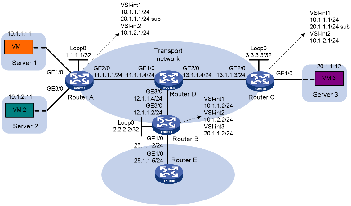
Procedure
1. On VM 1, VM 2, and VM 3, specify 10.1.1.1, 10.1.2.1, and 20.1.1.1 as the gateway address, respectively. (Details not shown.)
2. Configure IP addresses and unicast routing settings:
# Assign IP addresses to interfaces, as shown in Figure 18. (Details not shown.)
# Configure OSPF on all transport network routers (Routers A through D). (Details not shown.)
# Configure OSPF to advertise routes to networks 10.1.1.0/24, 10.1.2.0/24, 20.1.1.0/24, and 25.1.1.0/24 on Router B and Router E. (Details not shown.)
3. Configure Router A:
# Enable L2VPN.
<RouterA> system-view
[RouterA] l2vpn enable
# Create VSI vpna and VXLAN 10.
[RouterA] vsi vpna
[RouterA-vsi-vpna] vxlan 10
[RouterA-vsi-vpna-vxlan-10] quit
[RouterA-vsi-vpna] quit
# Create VSI vpnb and VXLAN 20.
[RouterA] vsi vpnb
[RouterA-vsi-vpnb] vxlan 20
[RouterA-vsi-vpnb-vxlan-20] quit
[RouterA-vsi-vpnb] quit
# Create VSI vpnc and VXLAN 30.
[RouterA] vsi vpnc
[RouterA-vsi-vpnc] vxlan 30
[RouterA-vsi-vpnc-vxlan-30] quit
[RouterA-vsi-vpnc] quit
# Assign an IP address to Loopback 0. The IP address will be used as the source IP address of the VXLAN tunnels to Router B and Router C.
[RouterA] interface loopback 0
[RouterA-Loopback0] ip address 1.1.1.1 255.255.255.255
[RouterA-Loopback0] quit
# Create a VXLAN tunnel to Router B. The tunnel interface name is Tunnel 1.
[RouterA] interface tunnel 1 mode vxlan
[RouterA-Tunnel1] source 1.1.1.1
[RouterA-Tunnel1] destination 2.2.2.2
[RouterA-Tunnel1] quit
# Create a VXLAN tunnel to Router C. The tunnel interface name is Tunnel 2.
[RouterA] interface tunnel 2 mode vxlan
[RouterA-Tunnel2] source 1.1.1.1
[RouterA-Tunnel2] destination 3.3.3.3
[RouterA-Tunnel2] quit
# Assign Tunnel 1 and Tunnel 2 to VXLAN 10.
[RouterA] vsi vpna
[RouterA-vsi-vpna] vxlan 10
[RouterA-vsi-vpna-vxlan-10] tunnel 1
[RouterA-vsi-vpna-vxlan-10] tunnel 2
[RouterA-vsi-vpna-vxlan-10] quit
[RouterA-vsi-vpna] quit
# Assign Tunnel 1 and Tunnel 2 to VXLAN 20.
[RouterA] vsi vpnb
[RouterA-vsi-vpnb] vxlan 20
[RouterA-vsi-vpnb-vxlan-20] tunnel 1
[RouterA-vsi-vpnb-vxlan-20] tunnel 2
[RouterA-vsi-vpnb-vxlan-20] quit
[RouterA-vsi-vpnb] quit
# Assign Tunnel 2 to VXLAN 30.
[RouterA] vsi vpnc
[RouterA-vsi-vpnc] vxlan 30
[RouterA-vsi-vpnc-vxlan-30] tunnel 2
[RouterA-vsi-vpnc-vxlan-30] quit
[RouterA-vsi-vpnc] quit
# Map GigabitEthernet 1/0 to VSI vpna.
[RouterA] interface gigabitethernet 1/0
[RouterA-GigabitEthernet1/0] xconnect vsi vpna
[RouterA-GigabitEthernet1/0] quit
# Map GigabitEthernet 3/0 to VSI vpnb.
[RouterA] interface gigabitethernet 3/0
[RouterA-GigabitEthernet3/0] xconnect vsi vpnb
[RouterA-GigabitEthernet3/0] quit
# Create VSI-interface 1 and assign the interface an IP address and a MAC address. The IP address will be used as the gateway address for VXLAN 10.
[RouterA] interface vsi-interface 1
[RouterA-Vsi-interface1] ip address 10.1.1.1 255.255.255.0
[RouterA-Vsi-interface1] mac-address 1-1-1
# Specify VSI-interface 1 as a distributed gateway and enable local proxy ARP on the interface.
[RouterA-Vsi-interface1] distributed-gateway local
[RouterA-Vsi-interface1] local-proxy-arp enable
[RouterA-Vsi-interface1] quit
# Create VSI-interface 2 and assign the interface an IP address and a MAC address. The IP address will be used as the gateway address for VXLAN 20.
[RouterA] interface vsi-interface 2
[RouterA-Vsi-interface2] ip address 10.1.2.1 255.255.255.0
[RouterA-Vsi-interface2] mac-address 2-2-2
# Specify VSI-interface 2 as a distributed gateway and enable local proxy ARP on the interface.
[RouterA-Vsi-interface2] distributed-gateway local
[RouterA-Vsi-interface2] local-proxy-arp enable
[RouterA-Vsi-interface2] quit
# Enable dynamic ARP entry synchronization for distributed VXLAN IP gateways.
[RouterA] arp distributed-gateway dynamic-entry synchronize
# Specify VSI-interface 1 as the gateway interface for VSI vpna. Assign subnet 10.1.1.0/24 to the VSI.
[RouterA] vsi vpna
[RouterA-vsi-vpna] gateway vsi-interface 1
[RouterA-vsi-vpna] gateway subnet 10.1.1.0 0.0.0.255
[RouterA-vsi-vpna] quit
# Specify VSI-interface 2 as the gateway interface for VSI vpnb.
[RouterA] vsi vpnb
[RouterA-vsi-vpnb] gateway vsi-interface 2
[RouterA-vsi-vpnb] quit
# Assign a secondary IP address to VSI-interface 1. The IP address will be used as the gateway address for VXLAN 30.
[RouterA] interface vsi-interface 1
[RouterA-Vsi-interface1] ip address 20.1.1.1 255.255.255.0 sub
[RouterA-Vsi-interface1] quit
# Specify VSI-interface 1 as the gateway interface for VSI vpnc. Assign subnet 20.1.1.0/24 to the VSI.
[RouterA] vsi vpnc
[RouterA-vsi-vpnc] gateway vsi-interface 1
[RouterA-vsi-vpnc] gateway subnet 20.1.1.0 0.0.0.255
[RouterA-vsi-vpnc] quit
# Configure a PBR policy for VXLAN 10. Set the policy name to vxlan10, and set the default next hop to 10.1.1.2 (VSI-interface 1 on Router B).
[RouterA] acl advanced 3000
[RouterA-acl-ipv4-adv-3000] rule 0 permit ip
[RouterA-acl-ipv4-adv-3000] quit
[RouterA] policy-based-route vxlan10 permit node 5
[RouterA-pbr-vxlan10-5] if-match acl 3000
[RouterA-pbr-vxlan10-5] apply default-next-hop 10.1.1.2
[RouterA-pbr-vxlan10-5] quit
# Configure a PBR policy for VXLAN 20. Set the policy name to vxlan20, and set the default next hop to 10.1.2.2 (VSI-interface 2 on Router B).
[RouterA] policy-based-route vxlan20 permit node 5
[RouterA-pbr-vxlan20-5] if-match acl 3000
[RouterA-pbr-vxlan20-5] apply default-next-hop 10.1.2.2
[RouterA-pbr-vxlan20-5] quit
# Apply policies vxlan10 and vxlan20 to VSI-interface 1 and VSI-interface 2, respectively.
[RouterA] interface vsi-interface 1
[RouterA-Vsi-interface1] ip policy-based-route vxlan10
[RouterA-Vsi-interface1] quit
[RouterA] interface vsi-interface 2
[RouterA-Vsi-interface2] ip policy-based-route vxlan20
[RouterA-Vsi-interface2] quit
4. Configure Router B:
# Enable L2VPN.
<RouterB> system-view
[RouterB] l2vpn enable
# Create VSI vpna and VXLAN 10.
[RouterB] vsi vpna
[RouterB-vsi-vpna] vxlan 10
[RouterB-vsi-vpna-vxlan-10] quit
[RouterB-vsi-vpna] quit
# Create VSI vpnb and VXLAN 20.
[RouterB] vsi vpnb
[RouterB-vsi-vpnb] vxlan 20
[RouterB-vsi-vpnb-vxlan-20] quit
[RouterB-vsi-vpnb] quit
# Create VSI vpnc and VXLAN 30.
[RouterB] vsi vpnc
[RouterB-vsi-vpnc] vxlan 30
[RouterB-vsi-vpnc-vxlan-30] quit
[RouterB-vsi-vpnc] quit
# Assign an IP address to Loopback 0. The IP address will be used as the source IP address of the VXLAN tunnels to Router A and Router C.
[RouterB] interface loopback 0
[RouterB-Loopback0] ip address 2.2.2.2 255.255.255.255
[RouterB-Loopback0] quit
# Create a VXLAN tunnel to Router A. The tunnel interface name is Tunnel 2.
[RouterB] interface tunnel 2 mode vxlan
[RouterB-Tunnel2] source 2.2.2.2
[RouterB-Tunnel2] destination 1.1.1.1
[RouterB-Tunnel2] quit
# Create a VXLAN tunnel to Router C. The tunnel interface name is Tunnel 3.
[RouterB] interface tunnel 3 mode vxlan
[RouterB-Tunnel3] source 2.2.2.2
[RouterB-Tunnel3] destination 3.3.3.3
[RouterB-Tunnel3] quit
# Assign Tunnel 2 to VXLAN 10.
[RouterB] vsi vpna
[RouterB-vsi-vpna] vxlan 10
[RouterB-vsi-vpna-vxlan-10] tunnel 2
[RouterB-vsi-vpna-vxlan-10] quit
[RouterB-vsi-vpna] quit
# Assign Tunnel 2 to VXLAN 20.
[RouterB] vsi vpnb
[RouterB-vsi-vpnb] vxlan 20
[RouterB-vsi-vpnb-vxlan-20] tunnel 2
[RouterB-vsi-vpnb-vxlan-20] quit
[RouterB-vsi-vpnb] quit
# Assign Tunnel 3 to VXLAN 30.
[RouterB] vsi vpnc
[RouterB-vsi-vpnc] vxlan 30
[RouterB-vsi-vpnc-vxlan-30] tunnel 3
[RouterB-vsi-vpnc-vxlan-30] quit
[RouterB-vsi-vpnc] quit
# Create VSI-interface 1 and assign the interface an IP address.
[RouterB] interface vsi-interface 1
[RouterB-Vsi-interface1] ip address 10.1.1.2 255.255.255.0
[RouterB-Vsi-interface1] quit
# Create VSI-interface 2 and assign the interface an IP address.
[RouterB] interface vsi-interface 2
[RouterB-Vsi-interface2] ip address 10.1.2.2 255.255.255.0
[RouterB-Vsi-interface2] quit
# Create VSI-interface 3 and assign the interface an IP address.
[RouterB] interface vsi-interface 3
[RouterB-Vsi-interface3] ip address 20.1.1.2 255.255.255.0
[RouterB-Vsi-interface3] quit
# Specify VSI-interface 1 as the gateway interface for VSI vpna.
[RouterB] vsi vpna
[RouterB-vsi-vpna] gateway vsi-interface 1
[RouterB-vsi-vpna] quit
# Specify VSI-interface 2 as the gateway interface for VSI vpnb.
[RouterB] vsi vpnb
[RouterB-vsi-vpnb] gateway vsi-interface 2
[RouterB-vsi-vpnb] quit
# Specify VSI-interface 3 as the gateway interface for VSI vpnc.
[RouterB] vsi vpnc
[RouterB-vsi-vpnc] gateway vsi-interface 3
[RouterB-vsi-vpnc] quit
5. Configure Router C:
# Enable L2VPN.
<RouterC> system-view
[RouterC] l2vpn enable
# Create VSI vpna and VXLAN 10.
[RouterC] vsi vpna
[RouterC-vsi-vpna] vxlan 10
[RouterC-vsi-vpna-vxlan-10] quit
[RouterC-vsi-vpna] quit
# Create VSI vpnb and VXLAN 20.
[RouterC] vsi vpnb
[RouterC-vsi-vpnb] vxlan 20
[RouterC-vsi-vpnb-vxlan-20] quit
[RouterC-vsi-vpnb] quit
# Create VSI vpnc and VXLAN 30.
[RouterC] vsi vpnc
[RouterC-vsi-vpnc] vxlan 30
[RouterC-vsi-vpnc-vxlan-30] quit
[RouterC-vsi-vpnc] quit
# Assign an IP address to Loopback 0. The IP address will be used as the source IP address of the VXLAN tunnels to Router A and Router B.
[RouterC] interface loopback 0
[RouterC-Loopback0] ip address 3.3.3.3 255.255.255.255
[RouterC-Loopback0] quit
# Create a VXLAN tunnel to Router A. The tunnel interface name is Tunnel 1.
[RouterC] interface tunnel 1 mode vxlan
[RouterC-Tunnel1] source 3.3.3.3
[RouterC-Tunnel1] destination 1.1.1.1
[RouterC-Tunnel1] quit
# Create a VXLAN tunnel to Router B. The tunnel interface name is Tunnel 3.
[RouterC] interface tunnel 3 mode vxlan
[RouterC-Tunnel3] source 3.3.3.3
[RouterC-Tunnel3] destination 2.2.2.2
[RouterC-Tunnel3] quit
# Assign Tunnel 1 to VXLAN 10.
[RouterC] vsi vpna
[RouterC-vsi-vpna] vxlan 10
[RouterC-vsi-vpna-vxlan-10] tunnel 1
[RouterC-vsi-vpna-vxlan-10] quit
[RouterC-vsi-vpna] quit
# Assign Tunnel 1 to VXLAN 20.
[RouterC] vsi vpnb
[RouterC-vsi-vpnb] vxlan 20
[RouterC-vsi-vpnb-vxlan-20] tunnel 1
[RouterC-vsi-vpnb-vxlan-20] quit
[RouterC-vsi-vpnb] quit
# Assign Tunnel 1 and Tunnel 3 to VXLAN 30.
[RouterC] vsi vpnc
[RouterC-vsi-vpnc] vxlan 30
[RouterC-vsi-vpnc-vxlan-30] tunnel 1
[RouterC-vsi-vpnc-vxlan-30] tunnel 3
[RouterC-vsi-vpnc-vxlan-30] quit
[RouterC-vsi-vpnc] quit
# Map GigabitEthernet 1/0 to VSI vpnc.
[RouterC] interface gigabitethernet 1/0
[RouterC-GigabitEthernet1/0] xconnect vsi vpnc
[RouterC-GigabitEthernet1/0] quit
# Create VSI-interface 1 and assign the interface an IP address and a MAC address. The IP address will be used as the gateway address for VXLAN 10.
[RouterC] interface vsi-interface 1
[RouterC-Vsi-interface1] ip address 10.1.1.1 255.255.255.0
[RouterC-Vsi-interface1] mac-address 1-1-1
# Specify VSI-interface 1 as a distributed gateway and enable local proxy ARP on the interface.
[RouterC-Vsi-interface1] distributed-gateway local
[RouterC-Vsi-interface1] local-proxy-arp enable
[RouterC-Vsi-interface1] quit
# Create VSI-interface 2 and assign the interface an IP address and a MAC address. The IP address will be used as the gateway address for VXLAN 20.
[RouterC] interface vsi-interface 2
[RouterC-Vsi-interface2] ip address 10.1.2.1 255.255.255.0
[RouterC-Vsi-interface2] mac-address 2-2-2
# Specify VSI-interface 2 as a distributed gateway and enable local proxy ARP on the interface.
[RouterC-Vsi-interface2] distributed-gateway local
[RouterC-Vsi-interface2] local-proxy-arp enable
[RouterC-Vsi-interface2] quit
# Enable dynamic ARP entry synchronization for distributed VXLAN IP gateways.
[RouterC] arp distributed-gateway dynamic-entry synchronize
# Specify VSI-interface 1 as the gateway interface for VSI vpna. Assign subnet 10.1.1.0/24 to the VSI.
[RouterC] vsi vpna
[RouterC-vsi-vpna] gateway vsi-interface 1
[RouterC-vsi-vpna] gateway subnet 10.1.1.0 0.0.0.255
[RouterC-vsi-vpna] quit
# Specify VSI-interface 2 as the gateway interface for VSI vpnb.
[RouterC] vsi vpnb
[RouterC-vsi-vpnb] gateway vsi-interface 2
[RouterC-vsi-vpnb] quit
# Assign a secondary IP address to VSI-interface 1. The IP address will be used as the gateway address for VXLAN 30.
[RouterC] interface vsi-interface 1
[RouterC-Vsi-interface1] ip address 20.1.1.1 255.255.255.0 sub
[RouterC-Vsi-interface1] quit
# Specify VSI-interface 1 as the gateway interface for VSI vpnc. Assign subnet 20.1.1.0/24 to the VSI.
[RouterC] vsi vpnc
[RouterC-vsi-vpnc] gateway vsi-interface 1
[RouterC-vsi-vpnc] gateway subnet 20.1.1.0 0.0.0.255
[RouterC-vsi-vpnc] quit
# Configure a PBR policy for the VXLANs. Set the policy name to vxlan, and set the default next hop to 20.1.1.2 (VSI-interface 1 on Router B).
[RouterC] acl advanced 3000
[RouterC-acl-ipv4-adv-3000] rule 0 permit ip
[RouterC-acl-ipv4-adv-3000] quit
[RouterC] policy-based-route vxlan permit node 5
[RouterC-pbr-vxlan-5] if-match acl 3000
[RouterC-pbr-vxlan-5] apply default-next-hop 20.1.1.2
[RouterC-pbr-vxlan-5] quit
# Apply policy vxlan to VSI-interface 1.
[RouterC] interface vsi-interface 1
[RouterC-Vsi-interface1] ip policy-based-route vxlan
[RouterC-Vsi-interface1] quit
Verifying the configuration
1. Verify the distributed VXLAN IP gateway settings on Router A:
# Verify that the VXLAN tunnel interfaces are up on Router A.
[RouterA] display interface tunnel 2
Tunnel2
Current state: UP
Line protocol state: UP
Description: Tunnel2 Interface
Bandwidth: 64 kbps
Maximum transmission unit: 1464
Internet protocol processing: Disabled
Output queue - Urgent queuing: Size/Length/Discards 0/100/0
Output queue - Protocol queuing: Size/Length/Discards 0/500/0
Output queue - FIFO queuing: Size/Length/Discards 0/75/0
Last clearing of counters: Never
Tunnel source 1.1.1.1, destination 3.3.3.3
Tunnel protocol/transport UDP_VXLAN/IP
Last 300 seconds input rate: 0 bytes/sec, 0 bits/sec, 0 packets/sec
Last 300 seconds output rate: 0 bytes/sec, 0 bits/sec, 0 packets/sec
Input: 0 packets, 0 bytes, 0 drops
# Verify that VSI-interface 1 is up.
[RouterA] display interface vsi-interface 1
Vsi-interface1
Current state: UP
Line protocol state: UP
Description: Vsi-interface1 Interface
Bandwidth: 1000000 kbps
Maximum transmission unit: 1500
Internet address: 10.1.1.1/24 (primary)
IP packet frame type: Ethernet II, hardware address: 0001-0001-0001
IPv6 packet frame type: Ethernet II, hardware address: 0001-0001-0001
Physical: Unknown, baudrate: 1000000 kbps
Last clearing of counters: Never
Last 300 seconds input rate: 0 bytes/sec, 0 bits/sec, 0 packets/sec
Last 300 seconds output rate: 0 bytes/sec, 0 bits/sec, 0 packets/sec
Input: 0 packets, 0 bytes, 0 drops
Output: 0 packets, 0 bytes, 0 drops
# Verify that the VXLAN tunnels have been assigned to VXLAN 10, and VSI-interface 1 is the gateway interface for VSI vpna.
[RouterA] display l2vpn vsi name vpna verbose
VSI Name: vpna
VSI Index : 0
VSI State : Up
MTU : 1500
Bandwidth : -
Broadcast Restrain : -
Multicast Restrain : -
Unknown Unicast Restrain: -
MAC Learning : Enabled
MAC Table Limit : -
MAC Learning rate : -
Drop Unknown : -
PW Redundancy : Slave
Flooding : Enabled
Service Class : -
Statistics : Disabled
Gateway interface : VSI-interface 1
VXLAN ID : 10
Tunnels:
Tunnel Name Link ID State Type Flood Proxy Split horizon
Tunnel1 0x5000001 Up Manual Disabled Enabled
Tunnel2 0x5000002 Up Manual Disabled Enabled
ACs:
AC Link ID State
GE1/0 0 Up
# Verify that Router A has created ARP entries for the VMs.
[RouterA] display arp
Type: S-Static D-Dynamic O-Openflow R-Rule M-Multiport I-Invalid
IP address MAC address SVLAN/VSI Interface/Link ID Aging Type
11.1.1.4 000c-29c1-5e46 -- GE1/0 19 D
10.1.1.2 3c8c-400d-867a 0 Tunnel1 20 D
10.1.1.11 0cda-41b5-cf09 0 0 20 D
10.1.2.2 3c8c-400d-867a 1 Tunnel1 20 D
10.1.2.11 0cda-41b5-cf89 1 0 20 D
20.1.1.12 0001-0001-0001 2 Tunnel2 19 D
2. Verify the configuration on the border gateway Router B:
# Verify that the VXLAN tunnel interfaces are up on Router B.
[RouterB] display interface tunnel 2
Tunnel2
Current state: UP
Line protocol state: UP
Description: Tunnel2 Interface
Bandwidth: 64 kbps
Maximum transmission unit: 1464
Internet protocol processing: Disabled
Output queue - Urgent queuing: Size/Length/Discards 0/100/0
Output queue - Protocol queuing: Size/Length/Discards 0/500/0
Output queue - FIFO queuing: Size/Length/Discards 0/75/0
Last clearing of counters: Never
Tunnel source 2.2.2.2, destination 1.1.1.1
Tunnel protocol/transport UDP_VXLAN/IP
Last 300 seconds input rate: 0 bytes/sec, 0 bits/sec, 0 packets/sec
Last 300 seconds output rate: 0 bytes/sec, 0 bits/sec, 0 packets/sec
Input: 0 packets, 0 bytes, 0 drops
Output: 0 packets, 0 bytes, 0 drops
# Verify that VSI-interface 1 is up.
[RouterB] display interface vsi-interface 1
Vsi-interface1
Current state: UP
Line protocol state: UP
Description: Vsi-interface1 Interface
Bandwidth: 1000000 kbps
Maximum transmission unit: 1500
Internet address: 10.1.1.2/24 (primary)
IP packet frame type: Ethernet II, hardware address: 0011-2200-0102
IPv6 packet frame type: Ethernet II, hardware address: 0011-2200-0102
Physical: Unknown, baudrate: 1000000 kbps
Last clearing of counters: Never
Last 300 seconds input rate: 0 bytes/sec, 0 bits/sec, 0 packets/sec
Last 300 seconds output rate: 0 bytes/sec, 0 bits/sec, 0 packets/sec
Input: 0 packets, 0 bytes, 0 drops
Output: 0 packets, 0 bytes, 0 drops
# Verify that the VXLAN tunnels have been assigned to VXLAN 10, and VSI-interface 1 is the gateway interface for VSI vpna.
[RouterB] display l2vpn vsi name vpna verbose
VSI Name: vpna
VSI Index : 0
VSI State : Up
MTU : 1500
Bandwidth : -
Broadcast Restrain : -
Multicast Restrain : -
Unknown Unicast Restrain: -
MAC Learning : Enabled
MAC Table Limit : -
MAC Learning rate : -
Drop Unknown : -
PW Redundancy : Slave
Flooding : Enabled
Service Class : -
Statistics : Disabled
Gateway interface : VSI-interface 1
VXLAN ID : 10
Tunnels:
Tunnel Name Link ID State Type Flood Proxy Split horizon
Tunnel1 0x5000001 Up Manual Disabled Enabled
Tunnel2 0x5000002 Up Manual Disabled Enabled
# Verify that Router B has created ARP entries for the VMs.
[RouterB] display arp
Type: S-Static D-Dynamic O-Openflow R-Rule M-Multiport I-Invalid
IP address MAC address SVLAN/VSI Interface/Link ID Aging Type
12.1.1.4 0000-fc00-00ab -- GE1/0 14 D
25.1.1.5 4431-9234-24bb -- GE1/0 17 D
10.1.1.1 0001-0001-0001 0 Tunnel2 17 D
10.1.1.11 0001-0001-0001 0 Tunnel2 20 D
10.1.2.1 0002-0002-0002 1 Tunnel2 17 D
10.1.2.11 0002-0002-0002 1 Tunnel2 20 D
20.1.1.1 0001-0001-0001 2 Tunnel3 17 D
20.1.1.12 0001-0001-0001 2 Tunnel3 20 D
# Verify that Router B has created FIB entries for the VMs.
[RouterB] display fib 10.1.1.11
Destination count: 1 FIB entry count: 1
Flag:
U:Usable G:Gateway H:Host B:Blackhole D:Dynamic S:Static
R:Relay F:FRR
Destination/Mask Nexthop Flag OutInterface/Token Label
10.1.1.11/32 10.1.1.11 UH Vsi1 Null
[RouterB] display fib 20.1.1.12
Destination count: 1 FIB entry count: 1
Flag:
U:Usable G:Gateway H:Host B:Blackhole D:Dynamic S:Static
R:Relay F:FRR
Destination/Mask Nexthop Flag OutInterface/Token Label
20.1.1.12/32 20.1.1.12 UH Vsi3 Null
3. Verify that the network connectivity for VMs meets the requirements:
# Verify that VM 1, VM 2, and VM 3 can ping each other. (Details not shown.)
# Verify that VM 1, VM 2, and VM 3 can ping GigabitEthernet 1/0 (25.1.1.5) on Router E for WAN access. (Details not shown.)
Example: Configuring distributed VXLAN IPv6 gateways
Network configuration
As shown in Figure 19:
· Configure VXLAN 10 and VXLAN 20 as unicast-mode VXLANs on Router A, Router B, and Router C to provide connectivity for the VMs across the network sites.
· Manually establish VXLAN tunnels and assign the tunnels to the VXLANs.
· Configure distributed VXLAN IP gateways on Router A and Router C to forward traffic between VXLANs.
· Configure Router B as a border gateway to forward traffic between the VXLANs and the WAN connected to Router E.
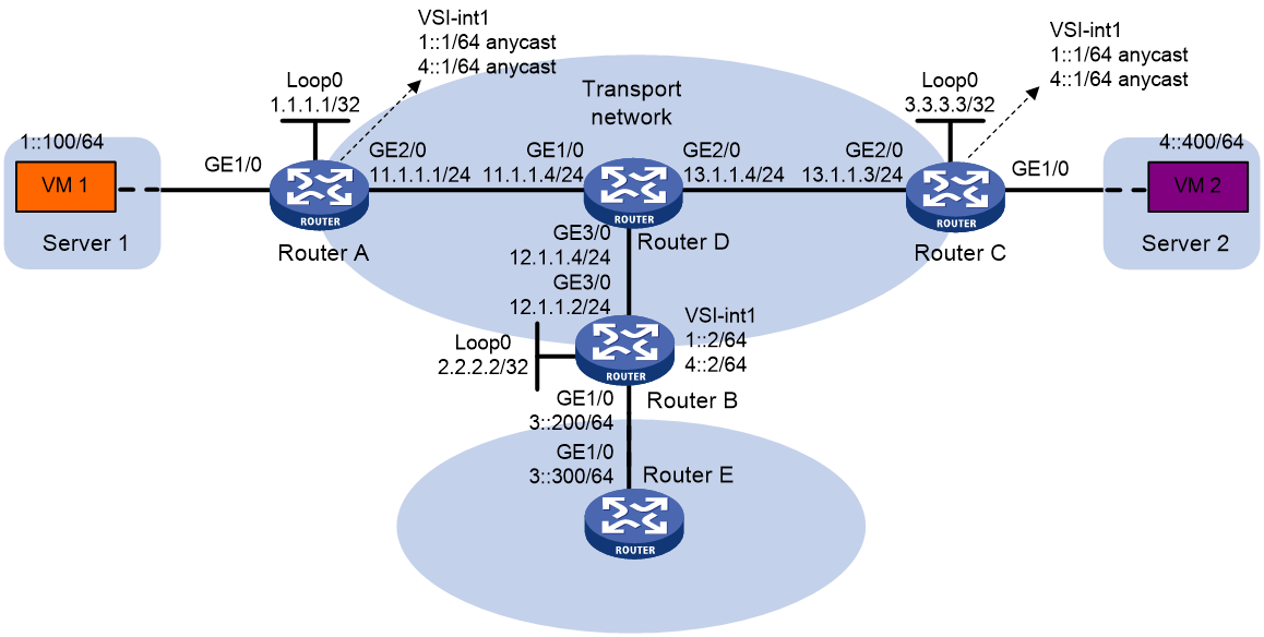
Procedure
1. On VM 1 and VM 2, specify 1::1 and 4::1 as the gateway address, respectively. (Details not shown.)
2. Configure IP addresses and unicast routing settings:
# Assign IP addresses to interfaces, as shown in Figure 19. (Details not shown.)
# Configure OSPF on all transport network routers (Routers A through D). (Details not shown.)
# Configure OSPFv3 to advertise routes to networks 1::/64, 4::/64, and 3::/64 on Router B and Router E. (Details not shown.)
3. Configure Router A:
# Enable L2VPN.
<RouterA> system-view
[RouterA] l2vpn enable
# Create VSI vpna and VXLAN 10.
[RouterA] vsi vpna
[RouterA-vsi-vpna] vxlan 10
[RouterA-vsi-vpna-vxlan-10] quit
[RouterA-vsi-vpna] quit
# Create VSI vpnb and VXLAN 20.
[RouterA] vsi vpnb
[RouterA-vsi-vpnb] vxlan 20
[RouterA-vsi-vpnb-vxlan-20] quit
[RouterA-vsi-vpnb] quit
# Assign an IP address to Loopback 0. The IP address will be used as the source IP address of the VXLAN tunnels to Router B and Router C.
[RouterA] interface loopback 0
[RouterA-Loopback0] ip address 1.1.1.1 255.255.255.255
[RouterA-Loopback0] quit
# Create a VXLAN tunnel to Router B. The tunnel interface name is Tunnel 1.
[RouterA] interface tunnel 1 mode vxlan
[RouterA-Tunnel1] source 1.1.1.1
[RouterA-Tunnel1] destination 2.2.2.2
[RouterA-Tunnel1] quit
# Create a VXLAN tunnel to Router C. The tunnel interface name is Tunnel 2.
[RouterA] interface tunnel 2 mode vxlan
[RouterA-Tunnel2] source 1.1.1.1
[RouterA-Tunnel2] destination 3.3.3.3
[RouterA-Tunnel2] quit
# Assign Tunnel 1 and Tunnel 2 to VXLAN 10.
[RouterA] vsi vpna
[RouterA-vsi-vpna] vxlan 10
[RouterA-vsi-vpna-vxlan-10] tunnel 1
[RouterA-vsi-vpna-vxlan-10] tunnel 2
[RouterA-vsi-vpna-vxlan-10] quit
[RouterA-vsi-vpna] quit
# Assign Tunnel 1 and Tunnel 2 to VXLAN 20.
[RouterA] vsi vpnb
[RouterA-vsi-vpnb] vxlan 20
[RouterA-vsi-vpnb-vxlan-20] tunnel 1
[RouterA-vsi-vpnb-vxlan-20] tunnel 2
[RouterA-vsi-vpnb-vxlan-20] quit
[RouterA-vsi-vpnb] quit
# Map GigabitEthernet 1/0 to VSI vpna.
[RouterA] interface gigabitethernet 1/0
[RouterA-GigabitEthernet1/0] xconnect vsi vpna
[RouterA-GigabitEthernet1/0] quit
# Create VSI-interface 1 and assign the interface two IPv6 anycast addresses. The IP addresses will be used as gateway addresses for VXLAN 10 and VXLAN 20.
[RouterA] interface vsi-interface 1
[RouterA-Vsi-interface1] ipv6 address 1::1/64 anycast
[RouterA-Vsi-interface1] ipv6 address 4::1/64 anycast
# Specify VSI-interface 1 as a distributed gateway and enable local ND proxy on the interface.
[RouterA-Vsi-interface1] distributed-gateway local
[RouterA-Vsi-interface1] local-proxy-nd enable
[RouterA-Vsi-interface1] quit
# Specify VSI-interface 1 as the gateway interface for VSI vpna. Assign subnet 1::1/64 to the VSI.
[RouterA] vsi vpna
[RouterA-vsi-vpna] gateway vsi-interface 1
[RouterA-vsi-vpna] gateway subnet 1::1 64
[RouterA-vsi-vpna] quit
# Specify VSI-interface 1 as the gateway interface for VSI vpnb. Assign subnet 4::1/64 to the VSI.
[RouterA] vsi vpnb
[RouterA-vsi-vpnb] gateway vsi-interface 1
[RouterA-vsi-vpnb] gateway subnet 4::1 64
[RouterA-vsi-vpnb] quit
# Configure an IPv6 static route. Set the destination address to 3::/64 and the next hop to 1::2.
[RouterA] ipv6 route-static 3:: 64 1::2
4. Configure Router B:
# Enable L2VPN.
<RouterB> system-view
[RouterB] l2vpn enable
# Create VSI vpna and VXLAN 10.
[RouterB] vsi vpna
[RouterB-vsi-vpna] vxlan 10
[RouterB-vsi-vpna-vxlan-10] quit
[RouterB-vsi-vpna] quit
# Create VSI vpnb and VXLAN 20.
[RouterB] vsi vpnb
[RouterB-vsi-vpnb] vxlan 20
[RouterB-vsi-vpnb-vxlan-20] quit
[RouterB-vsi-vpnb] quit
# Assign an IP address to Loopback 0. The IP address will be used as the source IP address of the VXLAN tunnels to Router A and Router C.
[RouterB] interface loopback 0
[RouterB-Loopback0] ip address 2.2.2.2 255.255.255.255
[RouterB-Loopback0] quit
# Create a VXLAN tunnel to Router A. The tunnel interface name is Tunnel 2.
[RouterB] interface tunnel 2 mode vxlan
[RouterB-Tunnel2] source 2.2.2.2
[RouterB-Tunnel2] destination 1.1.1.1
[RouterB-Tunnel2] quit
# Create a VXLAN tunnel to Router C. The tunnel interface name is Tunnel 3.
[RouterB] interface tunnel 3 mode vxlan
[RouterB-Tunnel3] source 2.2.2.2
[RouterB-Tunnel3] destination 3.3.3.3
[RouterB-Tunnel3] quit
# Assign Tunnel 2 and Tunnel 3 to VXLAN 10.
[RouterB] vsi vpna
[RouterB-vsi-vpna] vxlan 10
[RouterB-vsi-vpna-vxlan-10] tunnel 2
[RouterB-vsi-vpna-vxlan-10] tunnel 3
[RouterB-vsi-vpna-vxlan-10] quit
[RouterB-vsi-vpna] quit
# Assign Tunnel 2 and Tunnel 3 to VXLAN 20.
[RouterB] vsi vpnb
[RouterB-vsi-vpnb] vxlan 20
[RouterB-vsi-vpnb-vxlan-20] tunnel 2
[RouterB-vsi-vpnb-vxlan-20] tunnel 3
[RouterB-vsi-vpnb-vxlan-20] quit
[RouterB-vsi-vpnb] quit
# Create VSI-interface 1 and assign the interface IPv6 addresses.
[RouterB] interface vsi-interface 1
[RouterB-Vsi-interface1] ipv6 address 1::2/64
[RouterB-Vsi-interface1] ipv6 address 4::2/64
[RouterB-Vsi-interface1] quit
# Specify VSI-interface 1 as the gateway interface for VSI vpna.
[RouterB] vsi vpna
[RouterB-vsi-vpna] gateway vsi-interface 1
[RouterB-vsi-vpna] quit
# Specify VSI-interface 2 as the gateway interface for VSI vpnb.
[RouterB] vsi vpnb
[RouterB-vsi-vpnb] gateway vsi-interface 1
[RouterB-vsi-vpnb] quit
5. Configure Router C:
# Enable L2VPN.
<RouterC> system-view
[RouterC] l2vpn enable
# Create VSI vpna and VXLAN 10.
[RouterC] vsi vpna
[RouterC-vsi-vpna] vxlan 10
[RouterC-vsi-vpna-vxlan-10] quit
[RouterC-vsi-vpna] quit
# Create VSI vpnb and VXLAN 20.
[RouterC] vsi vpnb
[RouterC-vsi-vpnb] vxlan 20
[RouterC-vsi-vpnb-vxlan-20] quit
[RouterC-vsi-vpnb] quit
# Assign an IP address to Loopback 0. The IP address will be used as the source IP address of the VXLAN tunnels to Router A and Router B.
[RouterC] interface loopback 0
[RouterC-Loopback0] ip address 3.3.3.3 255.255.255.255
[RouterC-Loopback0] quit
# Create a VXLAN tunnel to Router A. The tunnel interface name is Tunnel 1.
[RouterC] interface tunnel 1 mode vxlan
[RouterC-Tunnel1] source 3.3.3.3
[RouterC-Tunnel1] destination 1.1.1.1
[RouterC-Tunnel1] quit
# Create a VXLAN tunnel to Router B. The tunnel interface name is Tunnel 3.
[RouterC] interface tunnel 3 mode vxlan
[RouterC-Tunnel3] source 3.3.3.3
[RouterC-Tunnel3] destination 2.2.2.2
[RouterC-Tunnel3] quit
# Assign Tunnel 1 and Tunnel 3 to VXLAN 10.
[RouterC] vsi vpna
[RouterC-vsi-vpna] vxlan 10
[RouterC-vsi-vpna-vxlan-10] tunnel 1
[RouterC-vsi-vpna-vxlan-10] tunnel 3
[RouterC-vsi-vpna-vxlan-10] quit
[RouterC-vsi-vpna] quit
#Assign Tunnel 1 and Tunnel 3 to VXLAN 20.
[RouterC] vsi vpnb
[RouterC-vsi-vpnb] vxlan 20
[RouterC-vsi-vpnb-vxlan-20] tunnel 1
[RouterC-vsi-vpnb-vxlan-20] tunnel 3
[RouterC-vsi-vpnb-vxlan-20] quit
[RouterC-vsi-vpnb] quit
# Map GigabitEthernet 1/0 to VSI vpnb.
[RouterC] interface gigabitethernet 1/0
[RouterC-GigabitEthernet1/0] xconnect vsi vpnb
[RouterC-GigabitEthernet1/0] quit
# Create VSI-interface 1 and assign the interface two IPv6 anycast addresses. The IP addresses will be used as gateway addresses for VXLAN 10 and VXLAN 20.
[RouterC] interface vsi-interface 1
[RouterC-Vsi-interface1] ipv6 address 1::1/64 anycast
[RouterC-Vsi-interface1] ipv6 address 4::1/64 anycast
# Specify VSI-interface 1 as a distributed gateway and enable local ND proxy on the interface.
[RouterC-Vsi-interface1] distributed-gateway local
[RouterC-Vsi-interface1] local-proxy-nd enable
[RouterC-Vsi-interface1] quit
# Specify VSI-interface 1 as the gateway interface for VSI vpna. Assign subnet 1::1/64 to the VSI.
[RouterC] vsi vpna
[RouterC-vsi-vpna] gateway vsi-interface 1
[RouterC-vsi-vpna] gateway subnet 1::1 64
[RouterC-vsi-vpna] quit
# Specify VSI-interface 1 as the gateway interface for VSI vpnb. Assign subnet 4::1/64 to the VSI.
[RouterC] vsi vpnb
[RouterC-vsi-vpnb] gateway vsi-interface 1
[RouterC-vsi-vpnb] gateway subnet 4::1 64
[RouterC-vsi-vpnb] quit
# Configure an IPv6 static route. Set the destination address to 3::/64 and the next hop to 4::2.
[RouterC] ipv6 route-static 3:: 64 4::2
Verifying the configuration
1. Verify the distributed VXLAN IP gateway settings on Router A:
# Verify that the VXLAN tunnel interfaces are up on Router A.
[RouterA] display interface tunnel 2
Tunnel2
Current state: UP
Line protocol state: UP
Description: Tunnel2 Interface
Bandwidth: 64 kbps
Maximum transmission unit: 1464
Internet protocol processing: Disabled
Output queue - Urgent queuing: Size/Length/Discards 0/100/0
Output queue - Protocol queuing: Size/Length/Discards 0/500/0
Output queue - FIFO queuing: Size/Length/Discards 0/75/0
Last clearing of counters: Never
Tunnel source 1.1.1.1, destination 3.3.3.3
Tunnel protocol/transport UDP_VXLAN/IP
Last 300 seconds input rate: 0 bytes/sec, 0 bits/sec, 0 packets/sec
Last 300 seconds output rate: 0 bytes/sec, 0 bits/sec, 0 packets/sec
Input: 0 packets, 0 bytes, 0 drops
Output: 0 packets, 0 bytes, 0 drops
# Verify that VSI-interface 1 is up.
[RouterA] display interface vsi-interface 1
Vsi-interface1
Current state: UP
Line protocol state: UP
Description: Vsi-interface1 Interface
Bandwidth: 1000000 kbps
Maximum transmission unit: 1500
Internet protocol processing: Disabled
IP packet frame type: Ethernet II, hardware address: 0011-2200-0102
IPv6 packet frame type: Ethernet II, hardware address: 0011-2200-0102
Physical: Unknown, baudrate: 1000000 kbps
Last clearing of counters: Never
Last 300 seconds input rate: 0 bytes/sec, 0 bits/sec, 0 packets/sec
Last 300 seconds output rate: 0 bytes/sec, 0 bits/sec, 0 packets/sec
Input: 0 packets, 0 bytes, 0 drops
Output: 0 packets, 0 bytes, 0 drops
# Verify that the VXLAN tunnels have been assigned to VXLAN 10 and VXLAN 20, and VSI-interface 1 is the gateway interface for VSIs vpna and vpnb.
[RouterA] display l2vpn vsi verbose
VSI Name: vpna
VSI Index : 0
VSI State : Up
MTU : 1500
Bandwidth : Unlimited
Broadcast Restrain : 5120 kbps
Multicast Restrain : 5120 kbps
Unknown Unicast Restrain: 5120 kbps
MAC Learning : Enabled
MAC Table Limit : -
Drop Unknown : Disabled
PW Redundancy : Slave
Flooding : Enabled
Service Class : -
Statistics : Disabled
Gateway Interface : VSI-interface 1
VXLAN ID : 10
Tunnel Statistics : Disabled
Tunnels:
Tunnel Name Link ID State Type Flood Proxy Split horizon
Tunnel1 0x5000001 Up Manual Disabled Enabled
Tunnel2 0x5000002 Up Manual Disabled Enabled
ACs:
AC Link ID State
GE1/0 0 Up
VSI Name: vpnb
VSI Index : 0
VSI State : Up
MTU : 1500
Bandwidth : Unlimited
Broadcast Restrain : 5120 kbps
Multicast Restrain : 5120 kbps
Unknown Unicast Restrain: 5120 kbps
MAC Learning : Enabled
MAC Table Limit : -
Drop Unknown : Disabled
PW Redundancy : Slave
Flooding : Enabled
Service Class : -
Statistics : Disabled
Gateway Interface : VSI-interface 1
VXLAN ID : 20
Tunnel Statistics : Disabled
Tunnels:
Tunnel Name Link ID State Type Flood Proxy Split horizon
Tunnel1 0x5000001 Up Manual Disabled Enabled
Tunnel2 0x5000002 Up Manual Disabled Enabled
# Verify that Router A has created neighbor entries for the VMs.
[RouterA] display ipv6 neighbors all
Type: S-Static D-Dynamic O-Openflow R-Rule I-Invalid
IPv6 address Link layer VID Interface State T Age
1::2 3c8c-400d-867a 0 Tunnel1 STALE D 7
1::100 0001-0000-0047 0 0 STALE D 22
4::400 0002-0000-0047 1 Tunnel2 REACH D 5
FE80::201:FF:FE00:47 0001-0000-0047 0 Tunnel1 REACH D 30
FE80::202:FF:FE00:0 0002-0000-0000 1 Tunnel2 REACH D 27
FE80::202:FF:FE00:47 0002-0000-0047 0 0 DELAY D 5
# Verify that Router A has created FIB entries for the VMs.
[RouterA] display ipv6 fib 4::400
Destination count: 1 FIB entry count: 1
Flag:
U:Usable G:Gateway H:Host B:Blackhole D:Dynamic S:Static
R:Relay F:FRR
Destination: 4::400 Prefix length: 128
Nexthop : 4::400 Flags: UH
Time stamp : 0x2c Label: Null
Interface : Tunnel2 Token: Invalid
[RouterA] display ipv6 fib 3::300
Destination count: 1 FIB entry count: 1
Flag:
U:Usable G:Gateway H:Host B:Blackhole D:Dynamic S:Static
R:Relay F:FRR
Destination: 3:: Prefix length: 40
Nexthop : 1::2 Flags: USGR
Time stamp : 0x23 Label: Null
Interface : Tunnel1 Token: Invalid
2. Verify the configuration on the border gateway Router B:
# Verify that the VXLAN tunnel interfaces are up on Router B.
[RouterB] display interface tunnel 2
Tunnel2
Current state: UP
Line protocol state: UP
Description: Tunnel2 Interface
Bandwidth: 64 kbps
Maximum transmission unit: 1464
Internet protocol processing: Disabled
Output queue - Urgent queuing: Size/Length/Discards 0/100/0
Output queue - Protocol queuing: Size/Length/Discards 0/500/0
Output queue - FIFO queuing: Size/Length/Discards 0/75/0
Last clearing of counters: Never
Tunnel source 2.2.2.2, destination 1.1.1.1
Tunnel protocol/transport UDP_VXLAN/IP
Last 300 seconds input rate: 0 bytes/sec, 0 bits/sec, 0 packets/sec
Last 300 seconds output rate: 0 bytes/sec, 0 bits/sec, 0 packets/sec
Input: 0 packets, 0 bytes, 0 drops
Output: 0 packets, 0 bytes, 0 drops
# Verify that VSI-interface 1 is up.
[RouterB] display interface vsi-interface 1
Vsi-interface1
Current state: UP
Line protocol state: UP
Description: Vsi-interface1 Interface
Bandwidth: 1000000 kbps
Maximum transmission unit: 1500
Internet protocol processing: Disabled
IP packet frame type: Ethernet II, hardware address: 0011-2200-0102
IPv6 packet frame type: Ethernet II, hardware address: 0011-2200-0102
Physical: Unknown, baudrate: 1000000 kbps
Last clearing of counters: Never
Last 300 seconds input rate: 0 bytes/sec, 0 bits/sec, 0 packets/sec
Last 300 seconds output rate: 0 bytes/sec, 0 bits/sec, 0 packets/sec
Input: 0 packets, 0 bytes, 0 drops
Output: 0 packets, 0 bytes, 0 drops
# Verify that the VXLAN tunnels have been assigned to VXLAN 10, and VSI-interface 1 is the gateway interface of VSI vpna.
[RouterB] display l2vpn vsi name vpna verbose
VSI Name: vpna
VSI Index : 0
VSI State : Up
MTU : 1500
Bandwidth : Unlimited
Broadcast Restrain : 5120 kbps
Multicast Restrain : 5120 kbps
Unknown Unicast Restrain: 5120 kbps
MAC Learning : Enabled
MAC Table Limit : -
Drop Unknown : Disabled
PW Redundancy : Slave
Flooding : Enabled
Service Class : -
Statistics : Disabled
Gateway interface : VSI-interface 1
VXLAN ID : 10
Tunnels:
Tunnel Name Link ID State Type Flood Proxy Split horizon
Tunnel1 0x5000001 Up Manual Disabled Enabled
Tunnel2 0x5000002 Up Manual Disabled Enabled
# Verify that Router B has created neighbor entries for the VMs.
[RouterB] display ipv6 neighbors all
Type: S-Static D-Dynamic O-Openflow R-Rule I-Invalid
IPv6 address Link layer VID Interface State T Age
3::300 0003-0000-0047 N/A GE1/0 DELAY D 3
FE80::203:FF:FE00:47 0003-0000-0047 N/A GE1/0 STALE D 222
1::100 0001-0000-0047 0 Tunnel2 STALE D 232
4::400 0002-0000-0047 1 Tunnel3 REACH D 3
FE80::201:FF:FE00:0 0001-0000-0000 0 Tunnel2 STALE D 237
FE80::201:FF:FE00:47 0001-0000-0047 N/A GE1/0 STALE D 222
FE80::202:FF:FE00:0 0002-0000-0000 1 Tunnel3 STALE D 345
# Verify that Router B has created FIB entries for the VMs.
[RouterB] display ipv6 fib 1::100
Destination count: 1 FIB entry count: 1
Flag:
U:Usable G:Gateway H:Host B:Blackhole D:Dynamic S:Static
R:Relay F:FRR
Destination: 1::100 Prefix length: 128
Nexthop : 1::100 Flags: UH
Time stamp : 0x21 Label: Null
Interface : Tunnel2 Token: Invalid
[RouterB] display ipv6 fib 4::400
Destination count: 1 FIB entry count: 1
Flag:
U:Usable G:Gateway H:Host B:Blackhole D:Dynamic S:Static
R:Relay F:FRR
Destination: 4:: Prefix length: 64
Nexthop : :: Flags: U
Time stamp : 0x19 Label: Null
Interface : Tunnel3 Token: Invalid
3. Verify that the network connectivity for the VMs meet the network requirements:
# Verify that VM 1 and VM 2 can ping each other. (Details not shown.)
# Verify that VM 1, VM 2, and GigabitEthernet 1/0 (3::300) on Router E can ping each other. (Details not shown.)
Example: Configuring a VSI subinterface on a centralized VXLAN IP gateway
Network configuration
As shown in Figure 20:
· Configure VXLAN 10 as a unicast-mode VXLAN on Router A, Router B, and Router C to provide connectivity for the VMs across the network sites.
· Configure a VSI subinterface on Router B to provide gateway services for VXLAN 10.
· Manually establish VXLAN tunnels and assign the tunnels to VXLAN 10.
· Enable remote-MAC address learning.
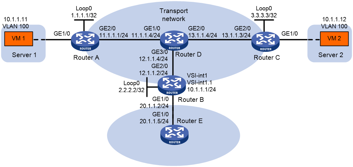
Procedure
1. On VM 1 and VM 2, specify 10.1.1.1 as the gateway address. (Details not shown.)
2. Configure IP addresses and unicast routing settings:
# Assign IP addresses to interfaces, as shown in Figure 20. (Details not shown.)
# Configure OSPF on all transport network routers (Routers A through D). (Details not shown.)
# Configure OSPF to advertise routes to networks 10.1.1.0/24 and 20.1.1.0/24 on Router B and Router E. (Details not shown.)
3. Configure Router A:
# Enable L2VPN.
<RouterA> system-view
[RouterA] l2vpn enable
# Create VSI vpna and VXLAN 10.
[RouterA] vsi vpna
[RouterA-vsi-vpna] vxlan 10
[RouterA-vsi-vpna-vxlan-10] quit
[RouterA-vsi-vpna] quit
# Assign an IP address to Loopback 0. The IP address will be used as the source IP address of the VXLAN tunnels to Router B and Router C.
[RouterA] interface loopback 0
[RouterA-Loopback0] ip address 1.1.1.1 255.255.255.255
[RouterA-Loopback0] quit
# Create a VXLAN tunnel to Router B. The tunnel interface name is Tunnel 1.
[RouterA] interface tunnel 1 mode vxlan
[RouterA-Tunnel1] source 1.1.1.1
[RouterA-Tunnel1] destination 2.2.2.2
[RouterA-Tunnel1] quit
# Create a VXLAN tunnel to Router C. The tunnel interface name is Tunnel 2.
[RouterA] interface tunnel 2 mode vxlan
[RouterA-Tunnel2] source 1.1.1.1
[RouterA-Tunnel2] destination 3.3.3.3
[RouterA-Tunnel2] quit
# Assign Tunnel 1 and Tunnel 2 to VXLAN 10.
[RouterA] vsi vpna
[RouterA-vsi-vpna] vxlan 10
[RouterA-vsi-vpna-vxlan-10] tunnel 1
[RouterA-vsi-vpna-vxlan-10] tunnel 2
[RouterA-vsi-vpna-vxlan-10] quit
[RouterA-vsi-vpna] quit
# Map GigabitEthernet 1/0 to VSI vpna.
[RouterA] interface gigabitethernet 1/0
[RouterA-GigabitEthernet1/0] xconnect vsi vpna
[RouterA-GigabitEthernet1/0] quit
4. Configure Router B:
# Enable L2VPN.
<RouterB> system-view
[RouterB] l2vpn enable
# Create VSI vpna and VXLAN 10.
[RouterB] vsi vpna
[RouterB-vsi-vpna] vxlan 10
[RouterB-vsi-vpna-vxlan-10] quit
[RouterB-vsi-vpna] quit
# Assign an IP address to Loopback 0. The IP address will be used as the source IP address of the VXLAN tunnels to Router A and Router C.
[RouterB] interface loopback 0
[RouterB-Loopback0] ip address 2.2.2.2 255.255.255.255
[RouterB-Loopback0] quit
# Create a VXLAN tunnel to Router A. The tunnel interface name is Tunnel 2.
[RouterB] interface tunnel 2 mode vxlan
[RouterB-Tunnel2] source 2.2.2.2
[RouterB-Tunnel2] destination 1.1.1.1
[RouterB-Tunnel2] quit
# Create a VXLAN tunnel to Router C. The tunnel interface name is Tunnel 3.
[RouterB] interface tunnel 3 mode vxlan
[RouterB-Tunnel3] source 2.2.2.2
[RouterB-Tunnel3] destination 3.3.3.3
[RouterB-Tunnel3] quit
# Assign Tunnel 2 and Tunnel 3 to VXLAN 10.
[RouterB] vsi vpna
[RouterB-vsi-vpna] vxlan 10
[RouterB-vsi-vpna-vxlan-10] tunnel 2
[RouterB-vsi-vpna-vxlan-10] tunnel 3
[RouterB-vsi-vpna-vxlan-10] quit
[RouterB-vsi-vpna] quit
# Create VSI-interface 1 and assign the interface a MAC address.
[RouterB] interface vsi-interface 1
[RouterB-Vsi-interface1] mac-address 1-1-1
[RouterB-Vsi-interface1] quit
# Create VSI-interface 1.1 and assign the interface an IP address and a MAC address. The IP address will be used as the gateway address for VXLAN 10.
[RouterB] interface vsi-interface 1.1
[RouterB-Vsi-interface1.1] ip address 10.1.1.1 255.255.255.0
[RouterB-Vsi-interface1.1] mac-address 1-1-1
# Configure VSI-interface 1.1 to terminate VLAN 100.
[RouterB-Vsi-interface1.1] vlan-type dot1q vid 100
[RouterB-Vsi-interface1.1] quit
# Specify VSI-interface 1 as the gateway interface for VSI vpna.
[RouterB] vsi vpna
[RouterB-vsi-vpna] gateway vsi-interface 1
[RouterB-vsi-vpna] quit
5. Configure Router C:
# Enable L2VPN.
<RouterC> system-view
[RouterC] l2vpn enable
# Create VSI vpna and VXLAN 10.
[RouterC] vsi vpna
[RouterC-vsi-vpna] vxlan 10
[RouterC-vsi-vpna-vxlan-10] quit
[RouterC-vsi-vpna] quit
# Assign an IP address to Loopback 0. The IP address will be used as the source IP address of the VXLAN tunnels to Router A and Router B.
[RouterC] interface loopback 0
[RouterC-Loopback0] ip address 3.3.3.3 255.255.255.255
[RouterC-Loopback0] quit
# Create a VXLAN tunnel to Router A. The tunnel interface name is Tunnel 1.
[RouterC] interface tunnel 1 mode vxlan
[RouterC-Tunnel1] source 3.3.3.3
[RouterC-Tunnel1] destination 1.1.1.1
[RouterC-Tunnel1] quit
# Create a VXLAN tunnel to Router B. The tunnel interface name is Tunnel 3.
[RouterC] interface tunnel 3 mode vxlan
[RouterC-Tunnel3] source 3.3.3.3
[RouterC-Tunnel3] destination 2.2.2.2
[RouterC-Tunnel3] quit
# Assign Tunnel 1 and Tunnel 3 to VXLAN 10.
[RouterC] vsi vpna
[RouterC-vsi-vpna] vxlan 10
[RouterC-vsi-vpna-vxlan-10] tunnel 1
[RouterC-vsi-vpna-vxlan-10] tunnel 3
[RouterC-vsi-vpna-vxlan-10] quit
[RouterC-vsi-vpna] quit
# Map GigabitEthernet 1/0 to VSI vpna.
[RouterC] interface gigabitethernet 1/0
[RouterC-GigabitEthernet1/0] xconnect vsi vpna
[RouterC-GigabitEthernet1/0] quit
Verifying the configuration
1. Verify the VXLAN IP gateway settings on Router B:
# Verify that the VSI interface and its subinterface are up.
[RouterB] display interface vsi-interface 1
Vsi-interface1
Current state: UP
Line protocol state: UP
Description: Vsi-interface1 Interface
Bandwidth: 1000000kbps
Maximum transmission unit: 1500
Internet protocol processing: Disabled
IP packet frame type: Ethernet II, hardware address: 0001-0001-0001
IPv6 packet frame type: Ethernet II, hardware address: 0001-0001-0001
Physical: Unknown, baudrate: 1000000 kbps
Last clearing of counters: Never
Last 300 seconds input rate: 0 bytes/sec, 0 bits/sec, 0 packets/sec
Last 300 seconds output rate: 0 bytes/sec, 0 bits/sec, 0 packets/sec
Input: 0 packets, 0 bytes, 0 drops
Output: 0 packets, 0 bytes, 0 drops
[RouterB] display interface vsi-interface 1.1
Vsi-interface1.1
Current state: UP
Line protocol state: UP
Description: Vsi-interface1.1 Interface
Bandwidth: 1000000kbps
Maximum transmission unit: 1500
Internet address: 10.1.1.1/24 (primary)
IP packet frame type: Ethernet II, hardware address: 0001-0001-0001
IPv6 packet frame type: Ethernet II, hardware address: 0001-0001-0001
Physical: Unknown, baudrate: 1000000 kbps
Last clearing of counters: Never
Last 300 seconds input rate: 0 bytes/sec, 0 bits/sec, 0 packets/sec
Last 300 seconds output rate: 0 bytes/sec, 0 bits/sec, 0 packets/sec
Input: 0 packets, 0 bytes, 0 drops
Output: 0 packets, 0 bytes, 0 drops
# Verify that Router B has created ARP entries for the VMs.
[RouterB] display arp
Type: S-Static D-Dynamic O-Openflow R-Rule M-Multiport I-Invalid
IP address MAC address SVLAN/VSI Interface/Link ID Aging Type
20.1.1.5 000c-29c1-5e46 -- GE1/0 19 D
10.1.1.11 0000-1234-0001 0 Tunnel2 20 D
10.1.1.12 0000-1234-0002 0 Tunnel3 19 D
# Verify that Router B has created FIB entries for the VMs.
[RouterB] display fib 10.1.1.11
Destination count: 1 FIB entry count: 1
Flag:
U:Usable G:Gateway H:Host B:Blackhole D:Dynamic S:Static
R:Relay F:FRR
Destination/Mask Nexthop Flag OutInterface/Token Label
10.1.1.11/32 10.1.1.11 UH Vsi1.1 Null
2. Verify the network connectivity for the VMs:
# Verify that VM 1 and VM 2 can ping each other. (Details not shown.)
# Verify that VM 1, VM 2, and GigabitEthernet 1/0 (20.1.1.5) on Router E can ping each other. (Details not shown.)
Configuring VXLAN-DCI
About VXLAN-DCI
VXLAN tunnels are used only for intra-data center connection. To provide Layer 2 connectivity between data centers over an IP transport network, you can use VXLAN data center interconnect (VXLAN-DCI) tunnels.
VXLAN-DCI network model
As shown in Figure 21, the VXLAN-DCI network contains edge devices (EDs) located at the edge of the transport network and VTEPs located at the data center sites. VXLAN tunnels are established between VTEPs and EDs, and VXLAN-DCI tunnels are established between EDs. VXLAN-DCI tunnels use VXLAN encapsulation. Each ED de-encapsulates received VXLAN packets and then re-encapsulates them based on the destination before forwarding them through a VXLAN or VXLAN-DCI tunnel.
Figure 21 VXLAN-DCI network model
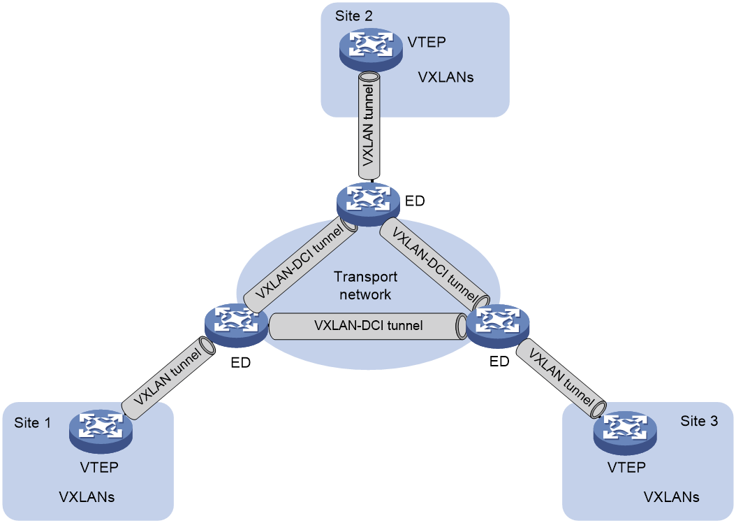
Working mechanisms
In a VXLAN-DCI network, VTEPs use MAC address entries to perform Layer 2 forwarding for VXLANs, and EDs perform Layer 3 forwarding based on dynamically learned ARP or ND entries.
As shown in Figure 22, a VSI interface uses the same IP address to provide gateway services for a VXLAN on different EDs. Local proxy ARP (for IPv4 sites) or local ND proxy (for IPv6 sites) is enabled on the EDs.
Figure 22 VXLAN-DCI working mechanisms
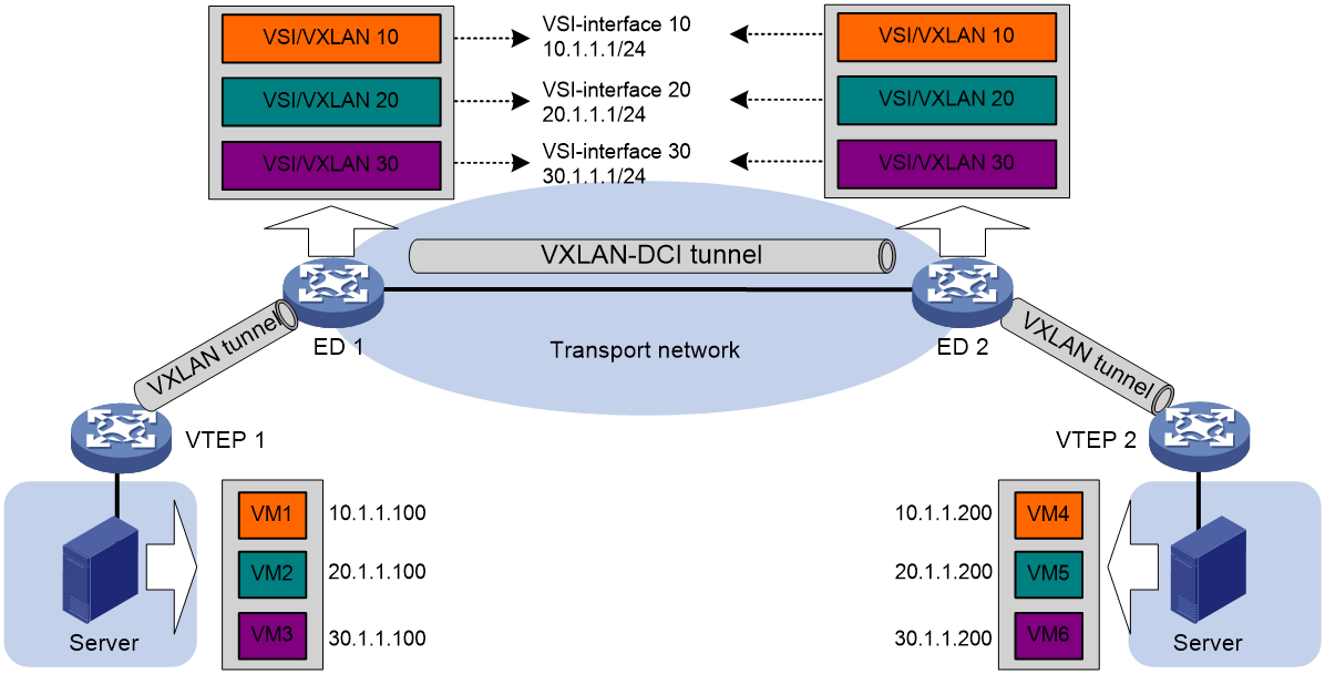
Intra-VXLAN traffic forwarding between sites
As shown in Figure 22, the network uses the following process to forward traffic in a VXLAN between sites (for example, from VM 1 to VM 4 in VXLAN 10):
1. VM 1 sends an ARP request to obtain the MAC address of VM 4.
2. VTEP 1 learns the MAC address of VM 1 and floods the ARP request in VXLAN 10.
3. ED 1 performs the following operations:
a. Removes the VXLAN encapsulation of the ARP request.
b. Creates an ARP entry for VM 1 and replies with the MAC address of VSI-interface 10 (the gateway interface for VXLAN 10). The ARP reply is sent to VTEP 1.
4. VTEP 1 removes the VXLAN encapsulation of the ARP reply, learns the MAC address of ED 1, and forwards the ARP reply to VM 1.
5. VM 1 creates an ARP entry for VM 4. The MAC address in the entry is the MAC address of VSI-interface 10 on ED 1.
6. ED 1 replaces the sender MAC address of the request with the MAC address of VSI-interface 10 on ED 1, and then floods the request to the remote EDs in VXLAN 10.
7. ED 2 performs the following operations:
a. Removes the VXLAN encapsulation of the ARP request.
b. Creates an ARP entry for VM 1. The entry contains VM 1's IP address (10.1.1.100), the MAC address of VSI-interface 10 on ED 1, and the incoming VXLAN-DCI tunnel interface.
c. Replaces the sender MAC address of the request with the MAC address of VSI-interface 10 on ED 2, and then floods the request on all VXLAN tunnels of VXLAN 10.
8. VTEP 2 removes the VXLAN encapsulation of the ARP request, learns the MAC address of ED 2, and floods the ARP request to the local site.
9. VM 4 creates an ARP entry for VM 1, and then sends a reply to VTEP 2. The MAC address in the ARP entry is the MAC address of VSI-interface 10 on ED 2.
10. VTEP 2 looks up the MAC address table and forwards the ARP reply to ED 2.
11. ED 2 performs the following operations:
a. Removes the VXLAN encapsulation of the ARP reply.
b. Creates an ARP entry for VM 4
c. Replaces the sender MAC address of the ARP reply with the MAC address of VSI-interface 10 on ED 2, and sends the reply to ED 1.
12. ED 1 performs the following operations:
a. Removes the VXLAN encapsulation of the ARP reply.
b. Creates an ARP entry for VM 4. The entry contains VM 4's IP address (10.1.1.200), the MAC address of VSI-interface 10 on ED 2, and the incoming VXLAN-DCI tunnel interface.
13. For subsequent traffic between VM 1 and VM 4, the VTEPs and EDs use their respective MAC address tables and ARP tables to make the forwarding decision.
Inter-VXLAN traffic forwarding between sites
As shown in Figure 22, the network uses the following process to forward traffic between VXLANs (for example, from VM 1 in VXLAN 10 to VM 5 in VXLAN 20):
1. VM 1 sends an ARP request to obtain the MAC address of the gateway at 10.1.1.1.
2. VTEP 1 learns the MAC address of VM 1 and floods the ARP request in VXLAN 10.
3. ED 1 performs the following operations:
a. Removes the VXLAN encapsulation of the ARP request.
b. Creates an ARP entry for VM 1 and replies with the MAC address of VSI-interface 10 (the gateway interface for VXLAN 10). The ARP reply is sent to VTEP 1.
4. VTEP 1 removes the VXLAN encapsulation of the ARP reply, learns the MAC address of ED 1, and forwards the ARP reply to VM 1.
5. VM 1 creates an ARP entry for the gateway and sends the packet destined for VM 5 to VTEP 1.
6. VTEP 1 looks up the MAC address table and forwards the packet to ED 1.
7. ED 1 performs the following operations:
a. Removes the VXLAN encapsulation of the packet and looks up the routing table based on the destination IP address.
b. Sends an ARP request to the local VTEP and remote ED of VXLAN 20 to obtain the MAC address of VM 5. In the ARP request, the sender IP address is 20.1.1.1, and the sender MAC address is the MAC address of VSI-interface 20 on ED 1.
8. ED 2 performs the following operations:
a. Removes the VXLAN encapsulation of the ARP request.
b. Replaces the sender MAC address of the request with the MAC address of VSI-interface 20 on ED 2, and then floods the request on all VXLAN tunnels of VXLAN 20.
9. VTEP 2 removes the VXLAN encapsulation of the ARP request, learns the MAC address of ED 2, and floods the ARP request to the local site.
10. VM 5 creates an ARP entry for ED 2 and sends a reply to VTEP 2. The MAC address in the ARP entry is the MAC address of VSI-interface 20 on ED 2.
11. VTEP 2 looks up the MAC address table and forwards the ARP reply to ED 2.
12. ED 2 performs the following operations:
a. Removes the VXLAN encapsulation of the ARP reply.
b. Creates an ARP entry for VM 5.
c. Sends a gratuitous ARP packet to ED 1. In the packet, the sender and target IP address is 20.1.1.200, and the sender MAC address is the MAC address of VSI-interface 20 on ED 2.
13. ED 1 performs the following operations:
a. Removes the VXLAN encapsulation of the packet.
b. Creates an ARP entry for VM 5. The entry contains VM 5's IP address (20.1.1.200), the MAC address of VSI-interface 20 on ED 2, and the incoming VXLAN-DCI tunnel interface.
14. For subsequent traffic between VM 1 and VM 5, the VTEPs and EDs use their respective MAC address tables and ARP tables to make the forwarding decision.
VXLAN-DCI tasks at a glance
To configure a VXLAN-DCI network, perform the following tasks:
· Configure routing protocols on the transport network for EDs to reach one another.
· Configure routing protocols on EDs and VTEPs for them to reach one another.
· Configure VXLANs on EDs and VTEPs, and set up VXLAN tunnels between EDs and VTEPs.
· Configure VXLAN-DCI on EDs, and set up VXLAN-DCI tunnels between EDs.
To configure VXLAN-DCI on an ED, perform the following tasks:
1. Creating a VXLAN on a VSI
For more information, see "Creating a VXLAN on a VSI."
2. Configuring a VXLAN-DCI tunnel
3. Assigning a VXLAN-DCI tunnel to a VXLAN
4. Configuring a gateway interface on an ED
5. Configuring optional parameters for a VSI interface
For more information, see "Configuring a VSI interface or VSI subinterface."
6. Configuring VXLAN packet parameters
¡ Setting the destination UDP port number of VXLAN packets
For more information, see "Setting the destination UDP port number of VXLAN packets."
¡ Configuring VXLAN packet check
For more information, see "Configuring VXLAN packet check."
7. Enabling packet statistics for VXLAN-DCI
¡ Enabling packet statistics for a VSI
For more information, see "Enabling packet statistics for a VSI."
¡ Enabling packet statistics for manually created VXLAN-DCI tunnels
|
|
NOTE: This chapter covers only the VXLAN-DCI configuration tasks available on an ED. For more information about basic VXLAN configuration and VXLAN IP gateway configuration, see "Configuring basic VXLAN features" and "Configuring VXLAN IP gateways." |
Configuring a VXLAN-DCI tunnel
Restrictions and guidelines
You must specify the tunnel source and destination IP addresses when you manually set up a VXLAN-DCI tunnel between EDs. As a best practice, do not configure the same tunnel source and destination addresses for different VXLAN-DCI tunnels on an ED.
This task provides basic VXLAN-DCI tunnel configuration. For more information about tunnel configuration and commands, see Layer 3—IP Services Configuration Guide and Layer 3—IP Services Command Reference.
Procedure
1. Enter system view.
system-view
2. Create a VXLAN-DCI tunnel interface and enter tunnel interface view.
interface tunnel tunnel-number mode vxlan-dci [ ipv6 ]
The endpoints of a tunnel must use the same tunnel mode.
3. Specify a source address for the tunnel. Choose one of the following tasks:
¡ Specify a source IP address.
source { ipv4-address | ipv6-address }
The specified IP address is used as the source IP address in the outer IP header of tunneled VXLAN packets.
¡ Specify a source interface.
source interface-type interface-number
The IP address of the specified interface is used as the source IP address in the outer IP header of tunneled VXLAN packets.
By default, no source address is specified for a tunnel.
4. Specify a destination IP address for the tunnel.
destination { ipv4-address | ipv6-address }
By default, no destination IP address is specified for a tunnel.
Specify the remote ED's IP address. This IP address will be the destination IP address in the outer IP header of tunneled VXLAN packets.
Assigning a VXLAN-DCI tunnel to a VXLAN
About this task
To provide connectivity for a VXLAN between two EDs, you must assign the VXLAN-DCI tunnel between the EDs to the VXLAN.
You can assign multiple VXLAN-DCI tunnels to a VXLAN, and configure a VXLAN-DCI tunnel to trunk multiple VXLANs. EDs use the VXLAN ID in VXLAN packets to identify the VXLAN. For a unicast-mode VXLAN, the system floods unknown unicast, multicast, and broadcast traffic to each VXLAN-DCI tunnel associated with the VXLAN.
Restrictions and guidelines
For full connectivity in the VXLAN, make sure the VXLAN contains the VXLAN-DCI tunnel between each pair of EDs in the VXLAN.
Procedure
1. Enter system view.
system-view
2. Enter VSI view.
vsi vsi-name
3. Enter VXLAN view.
vxlan vxlan-id
4. Assign a VXLAN-DCI tunnel to the VXLAN.
tunnel tunnel-number [ remote-vni vxlan-id ]
By default, a VXLAN does not contain any VXLAN-DCI tunnels.
If two data centers use different VXLANs to convey the same service, you can use the remote-vni vxlan-id option to specify the remote VXLAN ID on each ED for the VXLANs to communicate. The EDs will replace the local VXLAN ID in VXLAN packets with the remote VXLAN ID before sending the packets to a remote ED.
Configuring a gateway interface on an ED
1. Enter system view.
system-view
2. Create a VSI interface and enter VSI interface view.
interface vsi-interface vsi-interface-id
3. Assign an IP address to the VSI interface.
IPv4:
ip address ip-address { mask | mask-length } [ sub ]
IPv6:
See IPv6 basics in Layer 3—IP Services Configuration Guide.
By default, no IP address is assigned to a VSI interface.
4. Specify the VSI interface as a distributed gateway.
distributed-gateway local
By default, a VSI interface is not a distributed gateway.
5. Enable local proxy ARP or local ND proxy.
IPv4:
local-proxy-arp enable [ ip-range startIP to endIP ]
By default, local proxy ARP is disabled.
For more information about this command, see proxy ARP commands in Layer 3—IP Services Command Reference.
IPv6:
local-proxy-nd enable
By default, local ND proxy is disabled.
For more information about this command, see IPv6 basics commands in Layer 3—IP Services Command Reference.
6. Bring up the VSI interface.
undo shutdown
By default, a VSI interface is not manually shut down.
7. Return to system view.
quit
8. Enter VSI view.
vsi vsi-name
9. Specify the VSI interface as the gateway interface for the VSI.
gateway vsi-interface vsi-interface-id
By default, no gateway interface is specified for a VSI.
Enabling packet statistics for manually created VXLAN-DCI tunnels
About this task
Perform this task to enable packet statistics for manually created VXLAN-DCI tunnels on a per-tunnel interface basis. To display the packet statistics for VXLAN-DCI tunnels, use the display interface tunnel command in any view. To clear the packet statistics for VXLAN-DCI tunnels, use the reset counters interface tunnel command in user view.
Procedure
1. Enter system view.
system-view
2. Enter VXLAN-DCI tunnel interface view.
interface tunnel tunnel-number [ mode vxlan-dci ] [ ipv6 ]
3. Enable packet statistics for the tunnel.
statistics enable
By default, the packet statistics feature is disabled for manually created VXLAN-DCI tunnels.
Display and maintenance commands for VXLAN-DCI
Execute display commands in any view and reset commands in user view.
|
Task |
Command |
|
Display information about VSIs. |
display l2vpn vsi [ name vsi-name ] [ verbose ] |
|
Display information about tunnel interfaces. |
display interface [ tunnel [ number ] ] [ brief [ description | down ] ] |
|
Display VXLAN-DCI tunnel information for VXLANs. |
display vxlan tunnel [ vxlan-id vxlan-id [ tunnel tunnel-number ] ] |
|
Clear packet statistics on VSIs. |
reset l2vpn statistics vsi [ name vsi-name ] |
|
|
NOTE: For more information about the display interface tunnel command, see tunneling commands in Layer 3—IP Services Command Reference. |
VXLAN-DCI configuration examples
Example: Configuring a basic VXLAN-DCI network
Network configuration
As shown in Figure 23:
· Configure VXLAN 10 and VXLAN 20 as unicast-mode VXLANs on Router A, Router B, Router D, and Router E to provide connectivity for the VMs across the data center sites.
· Configure Router A and Router E as VTEPs, and Router B and Router D as EDs.
· Manually establish VXLAN tunnels and VXLAN-DCI tunnels, and assign the tunnels to the VXLANs.
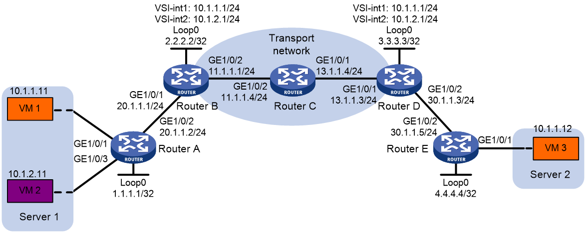
Procedure
1. Configure IP addresses and unicast routing settings:
# Assign IP addresses to interfaces, as shown in Figure 23. (Details not shown.)
# Configure OSPF on Routers A through E. (Details not shown.)
# Configure OSPF to advertise routes to networks 10.1.1.0/24 and 10.1.2.0/24 on Router B and Router D. (Details not shown.)
2. Configure Router A:
# Enable L2VPN.
<RouterA> system-view
[RouterA] l2vpn enable
# Create VSI vpna and VXLAN 10.
[RouterA] vsi vpna
[RouterA-vsi-vpna] vxlan 10
[RouterA-vsi-vpna-vxlan-10] quit
[RouterA-vsi-vpna] quit
# Create VSI vpnb and VXLAN 20.
[RouterA] vsi vpnb
[RouterA-vsi-vpnb] vxlan 20
[RouterA-vsi-vpnb-vxlan-20] quit
[RouterA-vsi-vpnb] quit
# Assign an IP address to Loopback 0. The IP address will be used as the source IP address of the VXLAN tunnel to Router B.
[RouterA] interface loopback 0
[RouterA-Loopback0] ip address 1.1.1.1 255.255.255.255
[RouterA-Loopback0] quit
# Create a VXLAN tunnel to Router B. The tunnel interface name is Tunnel 1.
[RouterA] interface tunnel 1 mode vxlan
[RouterA-Tunnel1] source 1.1.1.1
[RouterA-Tunnel1] destination 2.2.2.2
[RouterA-Tunnel1] quit
# Assign Tunnel 1 to VXLAN 10.
[RouterA] vsi vpna
[RouterA-vsi-vpna] vxlan 10
[RouterA-vsi-vpna-vxlan-10] tunnel 1
[RouterA-vsi-vpna-vxlan-10] quit
[RouterA-vsi-vpna] quit
# Assign Tunnel 1 to VXLAN 20.
[RouterA] vsi vpnb
[RouterA-vsi-vpnb] vxlan 20
[RouterA-vsi-vpnb-vxlan-20] tunnel 1
[RouterA-vsi-vpnb-vxlan-20] quit
[RouterA-vsi-vpnb] quit
# Map GigabitEthernet 1/0 to VSI vpna.
[RouterA] interface gigabitethernet 1/0
[RouterA-GigabitEthernet1/0] xconnect vsi vpna
[RouterA-GigabitEthernet1/0] quit
# Map GigabitEthernet 3/0 to VSI vpnb.
[RouterA] interface gigabitethernet 3/0
[RouterA-GigabitEthernet3/0] xconnect vsi vpnb
[RouterA-GigabitEthernet3/0] quit
3. Configure Router B:
# Enable L2VPN.
<RouterB> system-view
[RouterB] l2vpn enable
# Create VSI vpna and VXLAN 10.
[RouterB] vsi vpna
[RouterB-vsi-vpna] vxlan 10
[RouterB-vsi-vpna-vxlan-10] quit
[RouterB-vsi-vpna] quit
# Create VSI vpnb and VXLAN 20.
[RouterB] vsi vpnb
[RouterB-vsi-vpnb] vxlan 20
[RouterB-vsi-vpnb-vxlan-20] quit
[RouterB-vsi-vpnb] quit
# Assign an IP address to Loopback 0. The IP address will be used as the source IP address of the VXLAN tunnel to Router A and the VXLAN-DCI tunnel to Router D.
[RouterB] interface loopback 0
[RouterB-Loopback0] ip address 2.2.2.2 255.255.255.255
[RouterB-Loopback0] quit
# Create a VXLAN tunnel to Router A. The tunnel interface name is Tunnel 1.
[RouterB] interface tunnel 1 mode vxlan
[RouterB-Tunnel1] source 2.2.2.2
[RouterB-Tunnel1] destination 1.1.1.1
[RouterB-Tunnel1] quit
# Create a VXLAN-DCI tunnel to Router D. The tunnel interface name is Tunnel 2.
[RouterB] interface tunnel 2 mode vxlan-dci
[RouterB-Tunnel2] source 2.2.2.2
[RouterB-Tunnel2] destination 3.3.3.3
[RouterB-Tunnel2] quit
# Assign Tunnel 1 and Tunnel 2 to VXLAN 10.
[RouterB] vsi vpna
[RouterB-vsi-vpna] vxlan 10
[RouterB-vsi-vpna-vxlan-10] tunnel 1
[RouterB-vsi-vpna-vxlan-10] tunnel 2
[RouterB-vsi-vpna-vxlan-10] quit
[RouterB-vsi-vpna] quit
# Assign Tunnel 1 and Tunnel 2 to VXLAN 20.
[RouterB] vsi vpnb
[RouterB-vsi-vpnb] vxlan 20
[RouterB-vsi-vpnb-vxlan-20] tunnel 1
[RouterB-vsi-vpnb-vxlan-20] tunnel 2
[RouterB-vsi-vpnb-vxlan-20] quit
[RouterB-vsi-vpnb] quit
# Create VSI-interface 1 and assign the interface an IP address. The IP address will be used as the gateway address for VXLAN 10.
[RouterB] interface vsi-interface 1
[RouterB-Vsi-interface1] ip address 10.1.1.1 255.255.255.0
# Specify VSI-interface 1 as a distributed gateway and enable local proxy ARP on the interface.
[RouterB-Vsi-interface1] distributed-gateway local
[RouterB-Vsi-interface1] local-proxy-arp enable
[RouterB-Vsi-interface1] quit
# Create VSI-interface 2 and assign the interface an IP address. The IP address will be used as the gateway address for VXLAN 20.
[RouterB] interface vsi-interface 2
[RouterB-Vsi-interface2] ip address 10.1.2.1 255.255.255.0
# Specify VSI-interface 2 as a distributed gateway and enable local proxy ARP on the interface.
[RouterB-Vsi-interface2] distributed-gateway local
[RouterB-Vsi-interface2] local-proxy-arp enable
[RouterB-Vsi-interface2] quit
# Enable dynamic ARP entry synchronization for distributed VXLAN IP gateways.
[RouterB] arp distributed-gateway dynamic-entry synchronize
# Specify VSI-interface 1 as the gateway interface for VSI vpna.
[RouterB] vsi vpna
[RouterB-vsi-vpna] gateway vsi-interface 1
[RouterB-vsi-vpna] quit
# Specify VSI-interface 2 as the gateway interface for VSI vpnb.
[RouterB] vsi vpnb
[RouterB-vsi-vpnb] gateway vsi-interface 2
[RouterB-vsi-vpnb] quit
4. Configure Router D:
# Enable L2VPN.
<RouterD> system-view
[RouterD] l2vpn enable
# Create VSI vpna and VXLAN 10.
[RouterD] vsi vpna
[RouterD-vsi-vpna] vxlan 10
[RouterD-vsi-vpna-vxlan-10] quit
[RouterD-vsi-vpna] quit
# Create VSI vpnb and VXLAN 20.
[RouterD] vsi vpnb
[RouterD-vsi-vpnb] vxlan 20
[RouterD-vsi-vpnb-vxlan-20] quit
[RouterD-vsi-vpnb] quit
# Assign an IP address to Loopback 0. The IP address will be used as the source IP address of the VXLAN-DCI tunnel to Router B and the VXLAN tunnel to Router E.
[RouterD] interface loopback 0
[RouterD-Loopback0] ip address 3.3.3.3 255.255.255.255
[RouterD-Loopback0] quit
# Create a VXLAN tunnel to Router E. The tunnel interface name is Tunnel 1.
[RouterD] interface tunnel 1 mode vxlan
[RouterD-Tunnel1] source 3.3.3.3
[RouterD-Tunnel1] destination 4.4.4.4
[RouterD-Tunnel1] quit
# Create a VXLAN-DCI tunnel to Router B. The tunnel interface name is Tunnel 2.
[RouterD] interface tunnel 2 mode vxlan-dci
[RouterD-Tunnel2] source 3.3.3.3
[RouterD-Tunnel2] destination 2.2.2.2
[RouterD-Tunnel2] quit
# Assign Tunnel 1 and Tunnel 2 to VXLAN 10.
[RouterD] vsi vpna
[RouterD-vsi-vpna] vxlan 10
[RouterD-vsi-vpna-vxlan-10] tunnel 1
[RouterD-vsi-vpna-vxlan-10] tunnel 2
[RouterD-vsi-vpna-vxlan-10] quit
[RouterD-vsi-vpna] quit
# Assign Tunnel 2 to VXLAN 20.
[RouterD] vsi vpnb
[RouterD-vsi-vpnb] vxlan 20
[RouterD-vsi-vpnb-vxlan-20] tunnel 2
[RouterD-vsi-vpnb-vxlan-20] quit
[RouterD-vsi-vpnb] quit
# Create VSI-interface 1 and assign the interface an IP address. The IP address will be used as the gateway address for VXLAN 10.
[RouterD] interface vsi-interface 1
[RouterD-Vsi-interface1] ip address 10.1.1.1 255.255.255.0
# Specify VSI-interface 1 as a distributed gateway and enable local proxy ARP on the interface.
[RouterD-Vsi-interface1] distributed-gateway local
[RouterD-Vsi-interface1] local-proxy-arp enable
[RouterD-Vsi-interface1] quit
# Create VSI-interface 2 and assign the interface an IP address. The IP address will be used as the gateway address for VXLAN 20.
[RouterD] interface vsi-interface 2
[RouterD-Vsi-interface2] ip address 10.1.2.1 255.255.255.0
# Specify VSI-interface 2 as a distributed gateway and enable local proxy ARP on the interface.
[RouterD-Vsi-interface2] distributed-gateway local
[RouterD-Vsi-interface2] local-proxy-arp enable
[RouterD-Vsi-interface2] quit
# Enable dynamic ARP entry synchronization for distributed VXLAN IP gateways.
[RouterD] arp distributed-gateway dynamic-entry synchronize
# Specify VSI-interface 1 as the gateway interface for VSI vpna.
[RouterD] vsi vpna
[RouterD-vsi-vpna] gateway vsi-interface 1
[RouterD-vsi-vpna] quit
# Specify VSI-interface 2 as the gateway interface for VSI vpnb.
[RouterD] vsi vpnb
[RouterD-vsi-vpnb] gateway vsi-interface 2
[RouterD-vsi-vpnb] quit
5. Configure Router E:
# Enable L2VPN.
<RouterE> system-view
[RouterE] l2vpn enable
# Create VSI vpna and VXLAN 10.
[RouterE] vsi vpna
[RouterE-vsi-vpna] vxlan 10
[RouterE-vsi-vpna-vxlan-10] quit
[RouterE-vsi-vpna] quit
# Assign an IP address to Loopback 0. The IP address will be used as the source IP address of the VXLAN tunnel to Router D.
[RouterE] interface loopback 0
[RouterE-Loopback0] ip address 4.4.4.4 255.255.255.255
[RouterE-Loopback0] quit
# Create a VXLAN tunnel to Router D. The tunnel interface name is Tunnel 1.
[RouterE] interface tunnel 1 mode vxlan
[RouterE-Tunnel1] source 4.4.4.4
[RouterE-Tunnel1] destination 3.3.3.3
[RouterE-Tunnel1] quit
# Assign Tunnel 1 to VXLAN 10.
[RouterE] vsi vpna
[RouterE-vsi-vpna] vxlan 10
[RouterE-vsi-vpna-vxlan-10] tunnel 1
[RouterE-vsi-vpna-vxlan-10] quit
[RouterE-vsi-vpna] quit
# Map GigabitEthernet 1/0 to VSI vpna.
[RouterA] interface gigabitethernet 1/0
[RouterA-GigabitEthernet1/0] xconnect vsi vpna
[RouterA-GigabitEthernet1/0] quit
Verifying the configuration
1. Verify the VXLAN-DCI settings on the EDs. This example uses Router B.
# Verify that the VXLAN and VXLAN-DCI tunnel interfaces are up on Router B.
[RouterB] display interface tunnel
Tunnel1
Current state: UP
Line protocol state: UP
Description: Tunnel1 Interface
Bandwidth: 64 kbps
Maximum transmission unit: 64000
Internet protocol processing: Disabled
Output queue - Urgent queuing: Size/Length/Discards 0/100/0
Output queue - Protocol queuing: Size/Length/Discards 0/500/0
Output queue - FIFO queuing: Size/Length/Discards 0/75/0
Last clearing of counters: Never
Tunnel source 2.2.2.2, destination 1.1.1.1
Tunnel protocol/transport UDP_VXLAN/IP
Last 300 seconds input rate: 0 bytes/sec, 0 bits/sec, 0 packets/sec
Last 300 seconds output rate: 0 bytes/sec, 0 bits/sec, 0 packets/sec
Input: 0 packets, 0 bytes, 0 drops
Output: 0 packets, 0 bytes, 0 drops
Tunnel2
Current state: UP
Line protocol state: UP
Description: Tunnel2 Interface
Bandwidth: 64 kbps
Maximum transmission unit: 64000
Internet protocol processing: Disabled
Output queue - Urgent queuing: Size/Length/Discards 0/100/0
Output queue - Protocol queuing: Size/Length/Discards 0/500/0
Output queue - FIFO queuing: Size/Length/Discards 0/75/0
Last clearing of counters: Never
Tunnel source 2.2.2.2, destination 3.3.3.3
Tunnel protocol/transport UDP_VXLAN_DCI/IP
Last 300 seconds input rate: 0 bytes/sec, 0 bits/sec, 0 packets/sec
Last 300 seconds output rate: 0 bytes/sec, 0 bits/sec, 0 packets/sec
Input: 0 packets, 0 bytes, 0 drops
Output: 0 packets, 0 bytes, 0 drops
# Verify that VSI-interface 1 and VSI-interface 2 are up.
[RouterB] display interface vsi-interface
Vsi-interface1
Current state: UP
Line protocol state: UP
Description: Vsi-interface1 Interface
Bandwidth: 1000000 kbps
Maximum transmission unit: 1500
Internet address: 10.1.1.1/24 (primary)
IP packet frame type:PKTFMT_ETHNT_2, hardware address: 0011-2200-0102
IPv6 packet frame type:PKTFMT_ETHNT_2, hardware address: 0011-2200-0102
Physical: Unknown, baudrate: 1000000 kbps
Last clearing of counters: Never
Last 300 seconds input rate: 0 bytes/sec, 0 bits/sec, 0 packets/sec
Last 300 seconds output rate: 0 bytes/sec, 0 bits/sec, 0 packets/sec
Input: 0 packets, 0 bytes, 0 drops
Output: 0 packets, 0 bytes, 0 drops
Vsi-interface2
Current state: UP
Line protocol state: UP
Description: Vsi-interface2 Interface
Bandwidth: 1000000 kbps
Maximum transmission unit: 1500
Internet address: 10.1.2.1/24 (primary)
IP packet frame type:PKTFMT_ETHNT_2, hardware address: 0011-3300-0102
IPv6 packet frame type:PKTFMT_ETHNT_2, hardware address: 0011-3300-0102
Physical: Unknown, baudrate: 1000000 kbps
Last clearing of counters: Never
Last 300 seconds input rate: 0 bytes/sec, 0 bits/sec, 0 packets/sec
Last 300 seconds output rate: 0 bytes/sec, 0 bits/sec, 0 packets/sec
Input: 0 packets, 0 bytes, 0 drops
Output: 0 packets, 0 bytes, 0 drops
# Verify that the VXLAN and VXLAN-DCI tunnels have been assigned to VXLAN 10 and VXLAN 20, and the VSI interfaces are the gateway interfaces for their respective VSIs.
[RouterB] display l2vpn vsi verbose
VSI Name: vpna
VSI Index : 0
VSI State : Up
MTU : 1500
Bandwidth : -
Broadcast Restrain : 5120 kbps
Multicast Restrain : 5120 kbps
Unknown Unicast Restrain: 5120 kbps
MAC Learning : Enabled
MAC Table Limit : Unlimited
MAC Learning rate : Unlimited
Drop Unknown : Disabled
PW Redundancy : Slave
Service Class : -
Flooding : Enabled
Statistics : Disabled
Gateway interface : VSI-interface 1
VXLAN ID : 10
Tunnel Statistics : Disabled
Tunnels:
Tunnel Name Link ID State Type Flood Proxy
Tunnel1 0x5000001 Up Manual Disabled
Tunnel2 0x5000002 Up Manual Disabled
VSI Name: vpnb
VSI Index : 0
VSI State : Up
MTU : 1500
Bandwidth : -
Broadcast Restrain : 5120 kbps
Multicast Restrain : 5120 kbps
Unknown Unicast Restrain: 5120 kbps
MAC Learning : Enabled
MAC Table Limit : Unlimited
MAC Learning rate : Unlimited
Drop Unknown : Disabled
PW Redundancy : Slave
Service Class : -
Flooding : Enabled
Statistics : Disabled
Gateway interface : VSI-interface 2
VXLAN ID : 20
Tunnel Statistics : Disabled
Tunnels:
Tunnel Name Link ID State Type Flood Proxy
Tunnel1 0x5000001 Up Manual Disabled
Tunnel2 0x5000002 Up Manual Disabled
# Verify that Router B has created ARP entries for the VMs.
[RouterB] display arp
Type: S-Static D-Dynamic O-Openflow R-Rule M-Multiport I-Invalid
IP address MAC address SVLAN/VSI Interface/Link ID Aging Type
11.1.1.4 000c-29c1-5e46 11 Vlan11 19 D
10.1.1.11 0cda-41b5-cf09 0 Tunnel1 20 D
10.1.1.12 0011-4400-0102 0 Tunnel1 20 D
10.1.2.11 0cda-41b5-cf89 1 Tunnel2 20 D
2. Verify that VM 1, VM 2, and VM 3 can ping each other. (Details not shown.)
Configuring the VTEP as an OVSDB VTEP
About OVSDB VTEP
An H3C network virtualization controller can use the Open vSwitch Database (OVSDB) management protocol to deploy and manage VXLANs on VTEPs. To work with a controller, you must configure the VTEP as an OVSDB VTEP.
Working mechanisms
As shown in Figure 24, an OVSDB VTEP stores all of its VXLAN settings in the form of entries in an OVSDB database. The OVSDB database, OVSDB VTEP service, and the controller interact through the OVSDB server. The controller communicates with the OVSDB server through the OVSDB protocol to manage the OVSDB database. The OVSDB VTEP service reads and writes data in the OVSDB database through the OVSDB server.
The OVSDB VTEP service performs the following operations to manage the VXLAN settings on the VTEP:
· Converts data in the OVSDB database into VXLAN configuration and deploys the configuration to the VTEP. For example, create or remove a VXLAN or VXLAN tunnel.
· Adds site-facing interface information and the global source address of VXLAN tunnels to the OVSDB database. The information is reported to the controller by the OVSDB server.
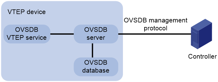
Protocols and standards
RFC 7047, The Open vSwitch Database Management Protocol
Restrictions and guidelines: OVSDB VTEP configuration
You can configure a VTEP both at the CLI and through a controller. As a best practice, do not manually remove the VXLAN configuration issued by the controller.
OVSDB VTEP tasks at a glance
To configure OVSDB VTEPs, perform the following tasks:
1. Setting up an OVSDB connection to a controller
¡ Configuring active SSL connection settings
¡ Configuring passive SSL connection settings
¡ Configuring active TCP connection settings
¡ Configuring passive TCP connection settings
3. Enabling the OVSDB VTEP service
4. Specifying a global source address for VXLAN tunnels
5. Specifying a VTEP access port
6. Enabling flood proxy on multicast VXLAN tunnels
If you use a flood proxy server, you must enable flood proxy globally on multicast tunnels.
Prerequisites for OVSDB VTEP configuration
Before you configure the VTEP as an OVSDB VTEP, enable L2VPN by using the l2vpn enable command.
Before you set up SSL connections to controllers, you must configure SSL as described in Security Configuration Guide.
Setting up an OVSDB connection to a controller
About OVSDB connection types
The OVSDB server supports the following types of OVSDB connections:
· Active SSL connection—The OVSDB server initiates an SSL connection to the controller.
· Passive SSL connection—The OVSDB server accepts the SSL connection from the controller.
· Active TCP connection—The OVSDB server initiates a TCP connection to the controller.
· Passive TCP connection—The OVSDB server accepts the TCP connection from the controller.
Restrictions and guidelines for OVSDB controller connection setup
When you set up OVSDB connections, follow these restrictions and guidelines:
· You can set up multiple OVSDB connections. For the device to establish the connections, you must enable the OVSDB server. You must disable and then re-enable the OVSDB server if it has been enabled.
· You must specify the same PKI domain and CA certificate file for all active and passive SSL connections.
Prerequisites for OVSDB controller connection setup
Make sure you have configured a PKI domain before specifying it for SSL. For more information about configuring a PKI domain, see Security Configuration Guide.
Configuring active SSL connection settings
1. Enter system view.
system-view
2. Specify a PKI domain for SSL.
ovsdb server pki domain domain-name
By default, no PKI domain is specified for SSL.
3. (Optional.) Specify a CA certificate file for SSL.
ovsdb server bootstrap ca-certificate ca-filename
By default, SSL uses the CA certificate file in the PKI domain.
If the specified CA certificate file does not exist, the device obtains a self-signed certificate from the controller. The obtained file uses the name specified for the ca-filename argument.
4. Set up an active SSL connection.
ovsdb server ssl ip ip-address port port-number
By default, the device does not have active OVSDB SSL connections.
You can set up a maximum of eight OVSDB SSL connections.
Configuring passive SSL connection settings
1. Enter system view.
system-view
2. Specify a PKI domain for SSL.
ovsdb server pki domain domain-name
By default, no PKI domain is specified for SSL.
3. (Optional.) Specify a CA certificate file for SSL.
ovsdb server bootstrap ca-certificate ca-filename
By default, SSL uses the CA certificate file in the PKI domain.
If the specified CA certificate file does not exist, the device obtains a self-signed certificate from the controller. The obtained file uses the name specified for the ca-filename argument.
4. Enable the device to listen for SSL connection requests.
ovsdb server pssl [ port port-number ]
By default, the device does not listen for SSL connection requests.
You can specify only one port to listen for OVSDB SSL connection requests.
Configuring active TCP connection settings
1. Enter system view.
system-view
2. Set up an active TCP connection.
ovsdb server tcp ip ip-address port port-number
By default, the device does not have active OVSDB TCP connections.
You can set up a maximum of eight active OVSDB TCP connections.
Configuring passive TCP connection settings
1. Enter system view.
system-view
2. Enable the device to listen for TCP connection requests.
ovsdb server ptcp [ port port-number ]
By default, the device does not listen for TCP connection requests.
You can specify only one port to listen for OVSDB TCP connection requests.
Enabling the OVSDB server
Prerequisites
Make sure you have complete OVSDB connection setup before you enable the OVSDB server. If you change OVSDB connection settings after the OVSDB server is enabled, you must disable and then re-enable the OVSDB server for the change to take effect.
Procedure
1. Enter system view.
system-view
2. Enable the OVSDB server.
ovsdb server enable
By default, the OVSDB server is disabled.
Enabling the OVSDB VTEP service
1. Enter system view.
system-view
2. Enable the OVSDB VTEP service.
vtep enable
By default, the OVSDB VTEP service is disabled.
Specifying a global source address for VXLAN tunnels
About this task
The VTEP reports the global VXLAN tunnel source address to the controller for VXLAN tunnel setup.
Restrictions and guidelines
For correct VXLAN deployment and VTEP management, do not manually specify tunnel-specific source addresses for VXLAN tunnels if OVSDB is used.
Procedure
1. Enter system view.
system-view
2. Specify a global source address for VXLAN tunnels.
tunnel global source-address { ipv4-address | ipv6 ipv6-address }
By default, no global source address is specified for VXLAN tunnels.
Specifying a VTEP access port
About this task
For the controller to manage a site-facing interface, you must specify the interface as a VTEP access port.
Procedure
1. Enter system view.
system-view
2. Enter interface view.
interface interface-type interface-number
3. Specify the interface as a VTEP access port.
vtep access port
By default, an interface is not a VTEP access port.
Enabling flood proxy on multicast VXLAN tunnels
About this task
If you use a flood proxy server, you must enable flood proxy globally on multicast tunnels. Then the multicast tunnels are converted into flood proxy tunnels. The VTEP sends broadcast, multicast, and unknown unicast traffic for a VXLAN to the flood proxy server through the tunnels. The flood proxy server then replicates and forwards flood traffic to remote VTEPs.
Procedure
1. Enter system view.
system-view
2. Enable flood proxy on multicast VXLAN tunnels.
vxlan tunnel flooding-proxy
By default, flood proxy is disabled on multicast VXLAN tunnels.
OVSDB VTEP configuration examples
Example: Configuring a unicast-mode VXLAN
Network configuration
As shown in Figure 25, configure the controller cluster to deploy unicast-mode VXLAN 10 to Router A through Router C. VXLAN 10 provides Layer 2 connectivity for the VMs across the network sites.
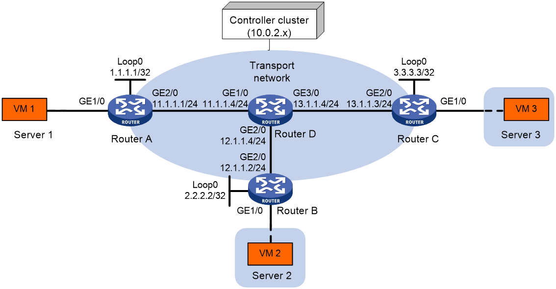
Procedure
1. Configure IP addresses and unicast routing settings:
# Assign IP addresses to the interfaces, as shown in Figure 25. (Details not shown.)
# Configure OSPF on all transport network routers (Routers A through D). (Details not shown.)
2. Configure Router A:
# Enable L2VPN.
<RouterA> system-view
[RouterA] l2vpn enable
# Configure active TCP connection settings.
[RouterA] ovsdb server tcp ip 10.0.2.15 port 6632
# Enable the OVSDB server.
[RouterA] ovsdb server enable
# Enable the OVSDB VTEP service.
[RouterA] vtep enable
# Assign an IP address to Loopback 0. Specify the IP address as the global source address for VXLAN tunnels.
[RouterA] interface loopback 0
[RouterA-LoopBack0] ip address 1.1.1.1 255.255.255.255
[RouterA-LoopBack0] quit
[RouterA] tunnel global source-address 1.1.1.1
# Specify site-facing interface GigabitEthernet 1/0 as a VTEP access port.
[RouterA] interface gigabitethernet 1/0
[RouterA-GigabitEthernet1/0] vtep access port
[RouterA-GigabitEthernet1/0] quit
3. Configure Router B:
# Enable L2VPN.
<RouterB> system-view
[RouterB] l2vpn enable
# Configure active TCP connection settings.
[RouterB] ovsdb server tcp 10.0.2.15 port 6632
# Enable the OVSDB server.
[RouterB] ovsdb server enable
# Enable the OVSDB VTEP service.
[RouterB] vtep enable
# Assign an IP address to Loopback 0. Specify the IP address as the global source address for VXLAN tunnels.
[RouterB] interface loopback 0
[RouterB-LoopBack0] ip address 2.2.2.2 255.255.255.255
[RouterB-LoopBack0] quit
[RouterB] tunnel global source-address 2.2.2.2
# Specify site-facing interface GigabitEthernet 1/0 as a VTEP access port.
[RouterB] interface gigabitethernet 1/0
[RouterB-GigabitEthernet1/0] vtep access port
[RouterB-GigabitEthernet1/0] quit
4. Configure Router C:
# Enable L2VPN.
<RouterC> system-view
[RouterC] l2vpn enable
# Configure active TCP connection settings.
[RouterC] ovsdb server tcp ip 10.0.2.15 port 6632
# Enable the OVSDB server.
[RouterC] ovsdb server enable
# Enable the OVSDB VTEP service.
[RouterC] vtep enable
# Assign an IP address to Loopback 0. Specify the IP address as the global source address for VXLAN tunnels.
[RouterC] interface loopback 0
[RouterC-LoopBack0] ip address 3.3.3.3 255.255.255.255
[RouterC-LoopBack0] quit
[RouterC] tunnel global source-address 3.3.3.3
# Specify site-facing interface GigabitEthernet 1/0 as a VTEP access port.
[RouterC] interface gigabitethernet 1/0
[RouterC-GigabitEthernet1/0] vtep access port
[RouterC-GigabitEthernet1/0] quit
5. Configure VXLAN settings on the controller. (Details not shown.)
Verifying the configuration
1. Verify the VXLAN settings on the VTEPs. This example uses Router A.
# Verify that the VXLAN tunnel interfaces on the VTEP are up.
[RouterA] display interface tunnel
Tunnel1
Current state: UP
Line protocol state: UP
Description: Tunnel1 Interface
Bandwidth: 64kbps
Maximum transmission unit: 1464
Internet protocol processing: Disabled
Output queue - Urgent queuing: Size/Length/Discards 0/100/0
Output queue - Protocol queuing: Size/Length/Discards 0/500/0
Output queue - FIFO queuing: Size/Length/Discards 0/75/0
Last clearing of counters: Never
Tunnel source 1.1.1.1, destination 2.2.2.2
Tunnel protocol/transport UDP_VXLAN/IP
Last 300 seconds input rate: 0 bytes/sec, 0 bits/sec, 0 packets/sec
Last 300 seconds output rate: 0 bytes/sec, 0 bits/sec, 0 packets/sec
Input: 0 packets, 0 bytes, 0 drops
Output: 0 packets, 0 bytes, 0 drops
# Verify that the VXLAN tunnels have been assigned to the VXLAN.
[RouterA] display l2vpn vsi verbose
VSI Name: evpn2014
VSI Index : 0
VSI State : Up
MTU : 1500
Bandwidth : -
Broadcast Restrain : -
Multicast Restrain : -
Unknown Unicast Restrain: -
MAC Learning : Enabled
MAC Table Limit : -
MAC Learning rate : -
Drop Unknown : -
PW Redundancy : Slave
Flooding : Enabled
Service Class : -
Statistics : Disabled
VXLAN ID : 10
Tunnel Statistics : Disabled
Tunnels:
Tunnel Name Link ID State Type Flood Proxy Split horizon
Tunnel1 0x5000001 Up Manual Disabled Enabled
Tunnel2 0x5000002 Up Manual Disabled Enabled
ACs:
AC Link ID State
GE1/0 0 Up
# Verify that the VTEP has learned the MAC addresses of remote VMs.
<RouterA> display l2vpn mac-address
MAC Address State VSI Name Link ID/Name Aging
cc3e-5f9c-6cdb Dynamic evpn2014 Tunnel1 Aging
cc3e-5f9c-23dc Dynamic evpn2014 Tunnel2 Aging
--- 2 mac address(es) found ---
2. Verify that VM 1, VM 2, and VM 3 can ping each other. (Details not shown.)
Example: Configuring flood proxy for a VXLAN
Network configuration
As shown in Figure 26:
· Configure the controller cluster to deploy VXLAN 10 to Router A, Router B, and Router C to provide Layer 2 connectivity for the VMs across the network sites.
· Enable flood proxy for VXLAN 10.
· Use the MAC address entries issued by the controller to direct traffic forwarding on Router A, Router B, and Router C.
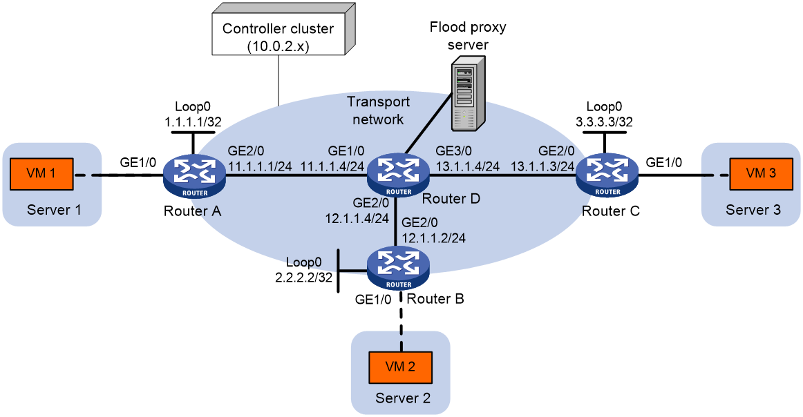
Procedure
1. Configure IP addresses and unicast routing settings:
# Assign IP addresses to the interfaces, as shown in Figure 26. (Details not shown.)
# Configure OSPF on all transport network routers (Routers A through D). (Details not shown.)
2. Configure Router A:
# Enable L2VPN.
<RouterA> system-view
[RouterA] l2vpn enable
# Configure active TCP connection settings.
[RouterA] ovsdb server tcp ip 10.0.2.15 port 6632
# Enable the OVSDB server.
[RouterA] ovsdb server enable
# Enable the OVSDB VTEP service.
[RouterA] vtep enable
# Assign an IP address to Loopback 0. Specify the IP address as the global source address for VXLAN tunnels.
[RouterA] interface loopback 0
[RouterA-LoopBack0] ip address 1.1.1.1 255.255.255.255
[RouterA-LoopBack0] quit
[RouterA] tunnel global source-address 1.1.1.1
# Specify site-facing interface GigabitEthernet 1/0 as a VTEP access port.
[RouterA] interface gigabitethernet 1/0
[RouterA-GigabitEthernet1/0] vtep access port
[RouterA-GigabitEthernet1/0] quit
# Disable source MAC check on transport-facing interface GigabitEthernet 2/0.
[RouterA] interface gigabitethernet 2/0
[RouterA-GigabitEthernet2/0] undo mac-address static source-check enable
[RouterA-GigabitEthernet2/0] quit
# Disable remote-MAC address learning.
[RouterA] vxlan tunnel mac-learning disable
# Enable flood proxy on multicast VXLAN tunnels.
[RouterA] vxlan tunnel flooding-proxy
3. Configure Router B:
# Enable L2VPN.
<RouterB> system-view
[RouterB] l2vpn enable
# Configure active TCP connection settings.
[RouterB] ovsdb server tcp ip 10.0.2.15 port 6632
# Enable the OVSDB server.
[RouterB] ovsdb server enable
# Enable the OVSDB VTEP service.
[RouterB] vtep enable
# Assign an IP address to Loopback 0. Specify the IP address as the global source address for VXLAN tunnels.
[RouterB] interface loopback 0
[RouterB-LoopBack0] ip address 2.2.2.2 255.255.255.255
[RouterB-LoopBack0] quit
[RouterB] tunnel global source-address 2.2.2.2
# Specify site-facing interface GigabitEthernet 1/0 as a VTEP access port.
[RouterB] interface gigabitethernet 1/0
[RouterB-GigabitEthernet1/0] vtep access port
[RouterB-GigabitEthernet1/0] quit
# Disable source MAC check on transport-facing interface GigabitEthernet 2/0.
[RouterB] interface gigabitethernet 2/0
[RouterB-GigabitEthernet2/0] undo mac-address static source-check enable
[RouterB-GigabitEthernet2/0] quit
# Disable remote-MAC address learning.
[RouterB] vxlan tunnel mac-learning disable
# Enable flood proxy on multicast VXLAN tunnels.
[RouterB] vxlan tunnel flooding-proxy
4. Configure Router C:
# Enable L2VPN.
<RouterC> system-view
[RouterC] l2vpn enable
# Configure active TCP connection settings.
[RouterC] ovsdb server tcp 10.0.2.15 port 6632
# Enable the OVSDB server.
[RouterC] ovsdb server enable
# Enable the OVSDB VTEP service.
[RouterC] vtep enable
# Assign an IP address to Loopback 0. Specify the IP address as the global source address for VXLAN tunnels.
[RouterC] interface loopback 0
[RouterC-LoopBack0] ip address 3.3.3.3 255.255.255.255
[RouterC-LoopBack0] quit
[RouterC] tunnel global source-address 3.3.3.3
# Specify site-facing interface GigabitEthernet 1/0 as a VTEP access port.
[RouterC] interface gigabitethernet 1/0
[RouterC-GigabitEthernet1/0] vtep access port
[RouterC-GigabitEthernet1/0] quit
# Disable source MAC check on transport-facing interface GigabitEthernet 2/0.
[RouterC] interface gigabitethernet 2/0
[RouterC-GigabitEthernet2/0] undo mac-address static source-check enable
[RouterC-GigabitEthernet2/0] quit
# Disable remote-MAC address learning.
[RouterC] vxlan tunnel mac-learning disable
# Enable flood proxy on multicast VXLAN tunnels.
[RouterC] vxlan tunnel flooding-proxy
5. Configure VXLAN settings on the controller, and configure the flood proxy server. (Details not shown.)
Verifying the configuration
1. Verify the VXLAN settings on the VTEPs. This example uses Router A.
# Verify that the VXLAN tunnel interfaces on the VTEP are up.
[RouterA] display interface tunnel
Tunnel1
Current state: UP
Line protocol state: UP
Description: Tunnel1 Interface
Bandwidth: 64kbps
Maximum transmission unit: 1464
Internet protocol processing: disabled
Output queue - Urgent queuing: Size/Length/Discards 0/100/0
Output queue - Protocol queuing: Size/Length/Discards 0/500/0
Output queue - FIFO queuing: Size/Length/Discards 0/75/0
Last clearing of counters: Never
Tunnel source 1.1.1.1, destination 2.2.2.2
Tunnel protocol/transport UDP_VXLAN/IP
Last 300 seconds input rate: 0 bytes/sec, 0 bits/sec, 0 packets/sec
Last 300 seconds output rate: 0 bytes/sec, 0 bits/sec, 0 packets/sec
Input: 0 packets, 0 bytes, 0 drops
Output: 0 packets, 0 bytes, 0 drops
# Verify that the VXLAN tunnels have been assigned to the VXLAN, and flood proxy has been enabled on the multicast VXLAN tunnel.
[RouterA] display l2vpn vsi verbose
VSI Name: evpn2014
VSI Index : 0
VSI State : Up
MTU : 1500
Bandwidth : -
Broadcast Restrain : -
Multicast Restrain : -
Unknown Unicast Restrain: -
MAC Learning : Enabled
MAC Table Limit : -
MAC Learning rate : -
Drop Unknown : -
PW Redundancy : Slave
Flooding : Enabled
Service Class : -
Statistics : Disabled
VXLAN ID : 10
Tunnel Statistics : Disabled
Tunnels:
Tunnel Name Link ID State Type Flood Proxy Split horizon
Tunnel1 0x5000001 Up Manual Disabled Enabled
Tunnel2 0x5000002 Up Manual Disabled Enabled
Tunnel3 0x5000003 Up Manual Enabled Enabled
ACs:
AC Link ID State
GE1/0 0 Up
# Verify that the VTEP has obtained the MAC addresses of remote VMs from the controller.
<RouterA> display l2vpn mac-address
MAC Address State VSI Name Link ID/Name Aging
cc3e-5f9c-6cdb OVSDB evpn2014 Tunnel1 NotAging
cc3e-5f9c-23dc OVSDB evpn2014 Tunnel2 NotAging
--- 2 mac address(es) found ---
2. Verify that VM 1, VM 2, and VM 3 can ping each other. (Details not shown.)
