- Table of Contents
-
- 09-MPLS Configuration Guide
- 00-Preface
- 01-MPLS SR configuration
- 02-Basic MPLS configuration
- 03-Static LSP configuration
- 04-LDP configuration
- 05-MPLS TE configuration
- 06-Static CRLSP configuration
- 07-RSVP configuration
- 08-Tunnel policy configuration
- 09-MPLS L3VPN configuration
- 10-MPLS L2VPN configuration
- 11-VPLS configuration
- 12-L2VPN access to L3VPN or IP backbone configuration
- 13-MPLS OAM configuration
- 14-MPLS protection switching configuration
- 15-MCE configuration
- Related Documents
-
| Title | Size | Download |
|---|---|---|
| 12-L2VPN access to L3VPN or IP backbone configuration | 115.92 KB |
Contents
Configuring L2VPN access to L3VPN or IP backbone
About L2VPN access to L3VPN or IP backbone
Benefits of L2VPN access to L3VPN or IP backbone
Implementation modes of L2VPN access to L3VPN or IP backbone
Configuring conventional L2VPN access to L3VPN or IP backbone
Configuring improved L2VPN access to L3VPN or IP backbone
Configuring an L2VE or L3VE interface
Restoring the default settings for an interface
Display and maintenance commands for L2VPN access to L3VPN or IP backbone
Configuring L2VPN access to L3VPN or IP backbone
About L2VPN access to L3VPN or IP backbone
Both MPLS L2VPN and VPLS support the L2VPN access to L3VPN or IP backbone feature. MPLS L2VPN provides point-to-point connections, and VPLS provides point-to-multipoint connections.
Unless otherwise specified, the term "MPLS L2VPN" in this document refers to both MPLS L2VPN and VPLS.
Benefits of L2VPN access to L3VPN or IP backbone
An MPLS L2VPN access network has the following features:
· Transparency—MPLS L2VPN is transparent to users and can be regarded as a physical link that directly connects users to the backbone.
· Cost reduction—MPLS L2VPN only requires PEs to identify users and user services, and P devices only forward packets based on labels. Therefore, you can use low-end devices as P devices to reduce your investment.
· Flexible networking—MPLS L2VPN supports various user access modes, such as Ethernet, ATM, and frame relay. It allows links that run different link layer protocols to communicate with each other through interworking.
Implementation modes of L2VPN access to L3VPN or IP backbone
L2VPN access to L3VPN or IP backbone can be implemented in two modes: conventional and improved.
Conventional L2VPN access to L3VPN or IP backbone
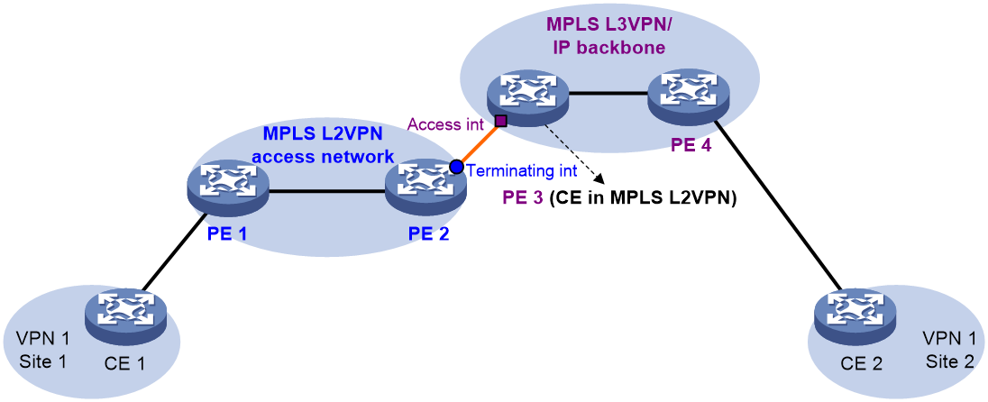
In the conventional networking mode, two devices are required to connect the MPLS L2VPN and the MPLS L3VPN or IP backbone. One device terminates the MPLS L2VPN, and the other device provides access to the MPLS L3VPN or IP backbone.
As shown in Figure 1, the access network is an MPLS L2VPN. PE 1 and PE 2 are PE devices in the MPLS L2VPN. PE 1 is connected to VPN site 1. PE 2 is connected to the MPLS L3VPN/IP backbone through PE 3. PE 3 acts as a PE in the MPLS L3VPN/IP backbone and as a CE in the MPLS L2VPN at the same time.
A packet from VPN site 1 to VPN site 2 is forwarded as follows:
1. A user in VPN site 1 sends a packet to PE 1.
2. PE 1 adds an MPLS label to the packet and sends the packet through a PW to PE 2.
3. PE 2 removes the MPLS label from the packet to obtain the original Layer 2 packet, and sends the packet to the connected CE (PE 3).
4. PE 3 looks up the routing table, and forwards the packet to the destination through the MPLS L3VPN or IP backbone.
Improved L2VPN access to L3VPN or IP backbone
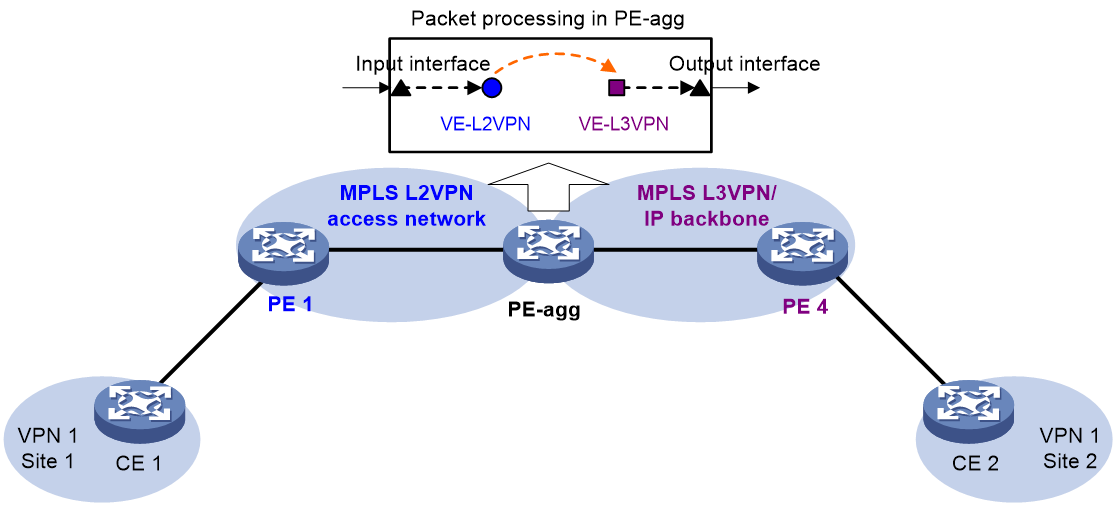
As shown in Figure 2, the PE Aggregation (PE-agg) device connects the MPLS L2VPN with the MPLS L3VPN or IP backbone. PE-agg terminates the MPLS L2VPN and provides access to the MPLS L3VPN or IP backbone.
Configure the PE-agg as follows so the PE-agg can implement the functions of both PE 2 and PE 3 in Figure 1:
1. Create a terminating virtual Ethernet (VE) interface on the PE-agg to terminate MPLS L2VPN packets.
This interface is referred to as the VE-L2VPN (L2VE) interface. The functions and configurations of the interface are similar to those of the terminating interface (Terminating int) in Figure 1.
2. Create an access VE interface on the PE-agg to provide access to the backbone, and configure the interface and the L2VE interface have the same interface number.
This interface is referred to as the VE-L3VPN (L3VE) interface. The functions and configurations of the interface are similar to those of the access interface (Access int) in Figure 1. The IP address of the L3VE interface must be in the same network segment as the AC interface of CE 1. When the backbone is an MPLS L3VPN, bind the VPN instance to the L3VE interface. The interface can then forward user packets through the VPN routes.
The L2VE interface directly delivers the obtained Layer 2 packets to the L3VE interface. The two VE interfaces can be considered directly connected through a physical link.
The PE-agg connects the MPLS L2VPN and the backbone through the L2VE interface and the L3VE interface. You can assume that the MPLS L2VPN is connected to the backbone through an Ethernet or VLAN link. If a user is not connected to the MPLS L2VPN through Ethernet or VLAN, you must configure MPLS L2VPN interworking on the user access PE (PE 1) and the L2VE interface of the PE-agg.
Configuring conventional L2VPN access to L3VPN or IP backbone
As shown in Figure 1, perform the following tasks to configure conventional L2VPN access to L3VPN or IP backbone:
1. Configure the MPLS L2VPN:
¡ Configure PE 1 and PE 2 as PE devices in the MPLS L2VPN.
¡ Configure CE 1 and PE 3 as CE devices in the MPLS L2VPN.
For more information about MPLS L2VPN configuration, see "Configuring MPLS L2VPN" and "Configuring VPLS."
2. Configure the MPLS L3VPN or IP backbone:
¡ Configure PE 3 and PE 4 as PE devices in the MPLS L3VPN or IP backbone.
¡ Configure CE 1 and CE 2 as CE devices in the MPLS L3VPN or IP backbone.
For more information about MPLS L3VPN configuration, see "Configuring MPLS L3VPN."
Configuring improved L2VPN access to L3VPN or IP backbone
Restrictions and guidelines
The L2VE interface and L3VE interface created on the PE-agg must have the same interface number.
To configure L2VPN access to MPLS L3VPN or IP backbone through multiple PWs, you must create multiple subinterfaces on the L2VE interface. All these subinterfaces on the L2VE interface must be connected to the same L3VE interface.
The VPLS access to L3VPN or IP backbone model does not support creating L2VE subinterfaces.
When packets entering an MPLS L3VPN or IP backbone carry VLAN tags, you must create an L3VE subinterface on the L3VE interface to terminate the VLAN tags. For more information about VLAN termination, see Layer 2—LAN Switching Configuration Guide.
Procedure
Configurations required on PEs and CEs are similar to those on the devices in the conventional L2VPN access scenario. The PE-agg requires the following configurations:
1. Create an L2VE interface:
a. Enter system view.
system-view
b. Create an L2VE interface or subinterface and enter its view.
interface ve-l2vpn { interface-number | interface-number.subnumber }
c. Bring up the interface.
undo shutdown
By default, the interface is up.
2. Create an L3VE interface:
a. Enter system view.
system-view
b. Create an L3VE interface or subinterface and enter its view.
interface ve-l3vpn { interface-number | interface-number.subnumber }
c. Bring up the interface.
undo shutdown
By default, the interface is up.
3. Configure MPLS L2VPN.
For more information, see "Configuring MPLS L2VPN" and "Configuring VPLS."
4. Configure MPLS L3VPN or IP routes.
For more information about MPLS L3VPN configuration, see "Configuring MPLS L3VPN."
Configuring an L2VE or L3VE interface
Configuring an L2VE interface
1. Enter system view.
system-view
2. Enter L2VE interface or subinterface view.
interface ve-l2vpn { interface-number | interface-number.subnumber }
3. Configure the description of the interface.
description text
By default, the description of the interface is VE-L2VPNnumber Interface, for example, VE-L2VPN100 Interface.
4. Set the MTU for the interface.
mtu size
The default MTU is 1500 bytes.
5. Set the expected bandwidth for the interface.
bandwidth bandwidth-value
The default expected bandwidth is 100000 kbps.
Configuring an L3VE interface
1. Enter system view.
system-view
2. Enter L3VE interface or subinterface view.
interface ve-l3vpn { interface-number | interface-number.subnumber }
3. Configure the description of the interface.
description text
By default, the description of the interface is VE-L3VPNnumber Interface, for example, VE-L3VPN100 Interface.
4. Set the MTU for the interface.
mtu size
The default MTU is 1500 bytes.
5. Set the expected bandwidth for the interface.
bandwidth bandwidth-value
The default expected bandwidth is 100000 kbps.
Restoring the default settings for an interface
Restrictions and guidelines
Restoring the default settings for an interface might interrupt ongoing network services. Make sure you are fully aware of the impact of the default command when you use it on a live network.
Procedure
1. Enter system view.
system-view
2. Enter L2VE interface view, L2VE subinterface view, L3VE interface view, or L3VE subinterface view.
interface interface-type { interface-number | interface-number.subnumber }
3. Restore the default settings for the interface.
default
Display and maintenance commands for L2VPN access to L3VPN or IP backbone
Execute display commands in any view and reset commands in user view.
|
Task |
Command |
|
Display information about L2VE interfaces interfaces. |
display interface [ ve-l2vpn [ interface-number | interface-number.subnumber ] ] [ brief [ description | down ] ] |
|
Display information about L3VE interfaces interfaces. |
display interface [ ve-l3vpn [ interface-number | interface-number.subnumber ] ] [ brief [ description | down ] ] |
|
Clear L2VE interface statistics. |
reset counters interface [ ve-l2vpn [ interface-number | interface-number.subnumber ] ] |
|
Clear L3VE interface statistics. |
reset counters interface [ ve-l3vpn [ interface-number | interface-number.subnumber ] ] |
