- Table of Contents
- Related Documents
-
| Title | Size | Download |
|---|---|---|
| 01-LISP configuration | 274.81 KB |
Contents
Support for multiple instances
Licensing requirements for LISP
Configuring LISP to support multiple instances
Enabling the ITR and ETR feature
Configuring LISP EID-to-RLOC mapping control
Configuring an ETR to accept mapping information in Map-Request messages
Setting the TTL value in Map-Reply messages
Setting the maximum number of mapping cache entries
Configuring an MS to permit only the specified RLOC address
Configuring virtual machine mobility
Querying mapping information in the LISP mapping database
Display and maintenance commands for LISP
Example: Configuring basic LISP
Example: Configuring LISP to support multiple instances
Example: Configuring LISP to support multiple xTRs
Example: Configuring virtual machine mobility across subnets
Configuring LISP
About LISP
The Locator/Identifier Separation Protocol (LISP) replaces the IP address space with two independent address spaces for traffic transmission: EID address space and RLOC address space. LISP-encapsulated packets in the core network are forwarded based on the RLOC addresses. When the packets reach the customer network, they are decapsulated and forwarded based on the EID addresses.
LISP benefits
LISP provides the following benefits:
· Reduction in traditional network diameter and routing table size.
· End node mobility. The end nodes can roam without changing their EIDs.
· Virtual machine mobility across Layer 3 networks and optimization of access paths from the moved virtual machines to the target network.
· Support for virtualization and multiple tenants.
LISP address spaces
LISP uses the following address spaces:
· EID address space—Endpoint Identifiers (EIDs) are host addresses of end nodes. Packets in a customer network use EIDs as source and destination addresses.
· RLOC address space—Routing Locators (RLOCs) are addresses of LISP routers. Packets in a core network use RLOCs as source and destination addresses.
Basic LISP network framework
Figure 1 shows a basic LISP network framework.
Figure 1 Basic LISP network framework

The LISP network includes the following elements:
· Core network—Uses Provider-Assigned (PA) addresses for traffic forwarding and routing.
· Customer network—Uses Provider-Independent (PI) addresses for host identification and internal routing.
· ITR—Ingress Tunnel Router. An ITR encapsulates packets received from the end nodes and sends them to the ETR.
· ETR—Egress Tunnel Router. An ETR decapsulates packets received from an ITR and sends the packets to their destination EIDs.
· xTR—A tunnel router that can implement the functionalities of both ITR and ETR.
· FHR—First Hop Router. In a Layer 2 multihop mobility topology, an FHR detects the existence of end hosts and notifies the Site GW xTR.
· Site GW xTR—Site Gateway xTR. In a Layer 2 multihop mobility topology, a Site GW xTR encapsulates and decapsulates the traffic.
LISP uses Ingress Tunnel Routers (ITRs) and Egress Tunnel Routers (ETRs) to connect the customer and core networks. The ITR and ETR process packets as follows:
1. After receiving an IP packet, the ITR performs an EID-to-RLOC mapping lookup for the destination EID in the packet.
2. The ITR encapsulates the IP packet into a LISP packet. The source RLOC in the LISP packet is the RLOC of the ITR and the destination RLOC is the RLOC of the target ETR.
3. The ITR forwards the LISP packet to the target ETR.
4. After receiving the LISP packet, the target ETR decapsulates the packet and forwards it to the destination EID.
LISP data plane
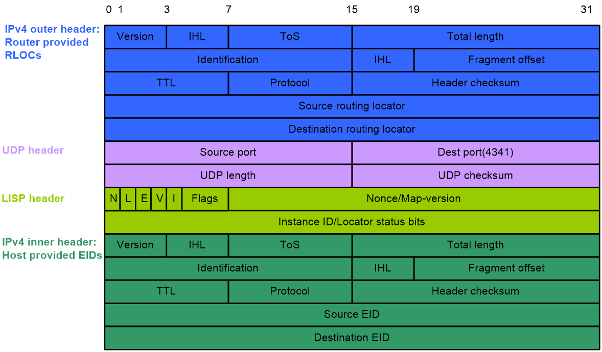
LISP encapsulates traffic sourced from the end hosts in the data plane. LISP supports IPv4-in-IPv4, IPv4-in-IPv6, IPv6-in-IPv4, and IPv6-in-IPv6 encapsulations.
|
|
NOTE: H3C LISP supports only IPv4-in-IPv4 encapsulation. |
Before entering the LISP tunnel, the traffic is added with a UDP header, a LISP header, and an outer header, with a total length of 36 to 56 bytes. Figure 2 shows the LISP IPv4-in-IPv4 header format.
Figure 2 LISP IPv4-in-IPv4 header format
LISP control plane
Basic concepts
LISP manages the EID-to-RLOC mapping information in the control plane.
· EID-to-RLOC mapping database—A database used by each ETR to store EID-to-RLOC mappings. All ETRs in a LISP site share the mapping information for this site.
· MS—Map-Server. A Map-Server learns and maintains the EID-to-RLOC mapping information in the Map-Register messages received from ETRs.
· MR—Map-Resolver. A Map-Resolver processes Map-Request messages sent by ITRs.
|
|
NOTE: A device can act as both an MS and an MR. |
LISP messages
The LISP control plane uses the following types of UDP-based messages:
· Map-Request—Sent by an ITR to an MR or an ETR to request EID-to-RLOC mapping information. The UDP source port number of the message is random and the destination port number is 4342.
· Map-Reply—Used by an ETR to respond to a Map-Request. The UDP source port number of the message is 4342. The UDP destination port number is the source port of the Map-Request message.
· Map-Register—Periodically sent by an ETR to register EID-to-RLOC mappings with an MS. The UDP source port number of the message is random and the destination port number is 4342.
· ECM—Encapsulated Control Message. A Map-Request message is encapsulated into an ECM message before it is sent from an ITR to an MR or forwarded from an MS to an ETR. During the encapsulation, an additional LISP header is added to the Map-Request message with the source and destination RLOCs. The UDP source port number of the ECM message is random and the destination port number is 4342.
· Map-Notify—Used by an MS to notify the ETR that the Map-Register message is received and processed.
· Map-ACK—Used by an ETR to acknowledge the receipt of a Map-Notify message.
EID-to-RLOC mapping registration
An ETR registers EID-to-RLOC mapping information with an MS as follows:
1. The ETR periodically sends a Map-Register message to the MS. The Map-Register message carries the EID-to-RLOC mapping information for the local LISP site.
2. When the MS receives the Map-Register message, it records the EID-to-RLOC mappings for the LISP site.
3. The MS sends a Map-Notify message to the ETR.
4. When the ETR receives the Map-Notify message, it sends a Map-ACK message to the MS.
ITR EID-to-RLOC mapping resolution
After receiving a packet from an end host in the LISP site, an ITR performs a lookup in its local mapping cache for the destination EID of the packet. If no mapping is found, a mapping resolution is initiated as follows:
1. The ITR encapsulates a Map-Request in an ECM message and sends the ECM message to the MR for EID-to-RLOC mapping resolution.
2. When the MR receives the ECM message, it performs the following operations:
a. Decapsulates the ECM message.
b. Forwards the Map-Request to the MS.
3. When the MS receives the Map-Request, it performs the following operations:
a. Searches its mapping database for an ETR that has registered the mapping information for the requested EID.
b. Encapsulates the Map-Request in an ECM message.
c. Sends the ECM message to the ETR.
4. When the ETR receives the ECM message, it performs the following operations:
a. Decapsulates the ECM message.
b. Searches its mapping database for the RLOC of the requested EID.
c. Returns the RLOC in a Map-Reply to the ITR.
5. When the ITR receives the Map-Reply, it checks the information in the message and updates its mapping cache.
For subsequent packets addressed to the same EID, ITR performs a LISP encapsulation and directly forwards the packets to the ETR according to the information in its mapping cache.
Support for multiple instances
The LISP network supports multiple instances. You can create multiple instances for LISP to separate and route traffic between different sites for tenants.
The multi-instance LISP feature implements the following functions:
· LISP supports virtualization by adding a 24-bit unique instance ID to both control messages and data packets.
· The control information, data flows, and EID-to-RLOC mappings in the database and mapping cache are all marked by instance IDs.
· Each instance ID can be mapped to a VPN Routing & Forwarding (VRF) instance name to implement multiple mapping caches on an edge device.
· LISP can implement virtualization at two levels. EIDs and RLOCs can be separately marked by different instance IDs.
Figure 3 shows three instances configured in a LISP network.

LISP application scenarios
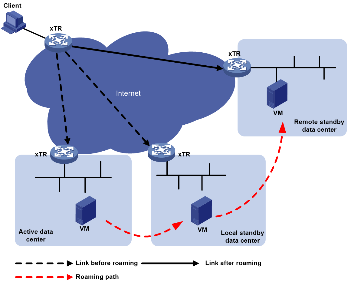
Virtual machine mobility across subnets applies to active-standby data centers, as shown in Figure 4.
Figure 4 Virtual machine mobility across subnets
Protocols and standards
· RFC 6830, The Locator/ID Separation Protocol (LISP)
· RFC 6833, Locator/ID Separation Protocol (LISP) Map-Server Interface
· RFC 6835, The Locator/ID Separation Protocol Internet Groper (LIG)
Licensing requirements for LISP
Data Software licenses are required for some devices to support LISP. For more information about licensing, see license management in Fundamentals Configuration Guide.
LISP tasks at a glance
To configure LISP, perform the following tasks:
1. Configuring basic LISP
b. (Optional.) Configuring LISP to support multiple instances
The LISP network supports multiple instances. Perform this task to create multiple instances to separate and route traffic between different sites for tenants.
c. Enabling the ITR and ETR feature
2. (Optional.) Configuring LISP EID-to-RLOC mapping control
¡ Configuring an ETR to accept mapping information in Map-Request messages
¡ Setting the TTL value in Map-Reply messages
¡ Setting the maximum number of mapping cache entries
¡ Configuring an MS to permit only the specified RLOC address
3. (Optional.) Configuring virtual machine mobility
4. (Optional.) Querying mapping information in the LISP mapping database
Configuring basic LISP
Enabling LISP
1. Enter system view.
system-view
2. Enable LISP and enter its view.
lisp
By default, LISP is disabled.
Configuring LISP to support multiple instances
1. Enter system view.
system-view
2. Enter LISP view.
lisp
3. Create a LISP VRF instance and enter its view.
vrf vrf-name
Enabling the ITR and ETR feature
1. Enter system view.
system-view
2. Enter LISP view or enter LISP VRF instance view.
¡ Enter LISP view.
lisp
¡ Perform the following commands in sequence to enter LISP VRF instance view:
lisp
vrf vrf-name
3. Enable the IPv4 ETR feature.
etr
By default, the IPv4 ETR feature is disabled.
4. Enable the IPv4 ITR feature.
itr
By default, the IPv4 ITR feature is disabled.
5. Configure an EID-to-RLOC mapping.
database-mapping eid-prefix prefix-length locator priority priority weight weight
By default, no EID-to-RLOC mapping is configured.
6. (Optional.) Configure an RLOC address in the mapping database as unreachable.
locator-down eid-prefix prefix-length locator
By default, no RLOC address in the mapping database is configured as unreachable.
An ETR does not use unreachable RLOC addresses in the mapping database as the addresses to reach the local site.
7. Specify an MS address for the IPv4 ETR.
¡ Configure the ETR to register with an MS without authentication.
etr map-server map-server-address authentication-mode none [ proxy-reply ]
¡ Configure the ETR to use SHA-1 to authenticate to an MS for registration.
etr map-server map-server-address authentication-mode sha-1 authentication-key { ciphertext | plaintext } string [ proxy-reply ]
By default, no MS address is specified for an IPv4 ETR.
You can specify a maximum of two MS addresses for an IPv4 ETR.
8. Specify an MR address for the IPv4 ITR.
itr map-resolver map-resolver-address
By default, no MR address is specified for an IPv4 ITR.
You can specify a maximum of two MR addresses for an IPv4 ITR.
9. (Optional.) Set the minimum length of EID prefixes permitted by an ITR in Map-Reply messages and permitted by an ETR in Map-Request messages.
shortest-eid-prefix-length prefix-length
By default, the minimum permitted length for the EID prefixes in Map-Reply messages and Map-Request messages is 16.
10. (Optional.) Specify an instance ID for EID prefixes.
xtr instance-id instance-id
By default, the instance ID for EID prefixes is 0.
Configuring an MR
1. Enter system view.
system-view
2. Enter LISP view or enter LISP VRF instance view.
¡ Enter LISP view.
lisp
¡ Perform the following commands in sequence to enter LISP VRF instance view:
lisp
vrf vrf-name
3. Enable the IPv4 MR feature.
map-resolver
By default, the IPv4 MR feature is disabled.
Configuring an MS
1. Enter system view.
system-view
2. Enter LISP view or enter LISP VRF instance view.
¡ Enter LISP view.
lisp
¡ Perform the following commands in sequence to enter LISP VRF instance view:
lisp
vrf vrf-name
3. Enable the IPv4 MS feature.
map-server
By default, the IPv4 MS feature is disabled.
4. Create a LISP site and enter its view.
site site-name
5. (Optional.) Configure a description for the LISP site.
description text
By default, the description for the LISP site is not configured.
6. (Optional.) Set the authentication mode for an MS.
authentication-mode { none | sha-1 authentication-key { ciphertext | plaintext } string }
By default, no authentication mode is set for an MS.
The ETR must use the same key as the MS for successful authentication.
7. Configure an MS to permit an EID prefix for registration.
eid-prefix eid-prefix prefix-length [ instance-id id ] [ accept-more-specifics ]
By default, an MS does not permit any EID prefixes.
For an ETR to successfully register with an MS, you must configure the MS to permit the same EID prefixes configured on the ETR by using the database-mapping command.
The instance ID must be the same as that specified by using the xtr instance-id command.
Configuring LISP EID-to-RLOC mapping control
Configuring an ETR to accept mapping information in Map-Request messages
About this task
An ITR can include its EID-to-RLOC mapping information in Map-Request messages if itself is an ETR. Perform this task to configure an ETR to accept and cache the mapping information in the Map-Request messages.
Procedure
1. Enter system view.
system-view
2. Enter LISP view or enter LISP VRF instance view.
¡ Enter LISP view.
lisp
¡ Perform the following commands in sequence to enter LISP VRF instance view:
lisp
vrf vrf-name
3. Configure an ETR to accept the mapping information in Map-Request messages.
etr accept-map-request-mapping [ verify ]
By default, an ETR does not accept the mapping information in Map-Request messages.
Setting the TTL value in Map-Reply messages
About this task
When an ETR responds to an ITR with Map-Reply messages, the ETR sets a TTL value in the messages. The ITR sets the TTL value for the cache entries according to the TTL value in these messages.
Procedure
1. Enter system view.
system-view
2. Enter LISP view or enter LISP VRF instance view.
¡ Enter LISP view.
lisp
¡ Perform the following commands in sequence to enter LISP VRF instance view:
lisp
vrf vrf-name
3. Set the TTL value in Map-Reply messages.
etr map-cache-ttl ttl
By default, the TTL value in Map-Reply messages is 1440 minutes.
Setting the maximum number of mapping cache entries
About this task
This task allows you to limit the size of the mapping cache table.
Procedure
1. Enter system view.
system-view
2. Enter LISP view or enter LISP VRF instance view.
¡ Enter LISP view.
lisp
¡ Perform the following commands in sequence to enter LISP VRF instance view:
lisp
vrf vrf-name
3. Set the maximum number of EID-to-RLOC mapping cache entries.
map-cache-limit cache-limit
By default, the maximum number of EID-to-RLOC mapping cache entries is not set.
Configuring an MS to permit only the specified RLOC address
Restrictions and guidelines
Perform this task only on an MS.
An MS configured with this feature permits only the specified RLOC addresses in Map-Register messages to be successfully registered.
Procedure
1. Enter system view.
system-view
2. Enter LISP view or enter LISP VRF instance view.
¡ Enter LISP view.
lisp
¡ Perform the following commands in sequence to enter LISP VRF instance view:
lisp
vrf vrf-name
3. Enter LISP site view.
site site-name
4. Configure an MS to permit only the specified RLOC address.
allowed-locator rloc-address
By default, an MS permits all RLOC addresses.
You can configure the MS to permit a maximum of eight RLOC addresses.
Configuring virtual machine mobility
5. Enter system view.
system-view
6. Enter LISP view or enter LISP VRF instance view.
¡ Enter LISP view.
lisp
¡ Perform the following commands in sequence to enter LISP VRF instance view:
lisp
vrf vrf-name
7. Create a dynamic EID detection policy and enter its view.
dynamic-eid dynamic-eid-name
Only the hosts that match the specified dynamic EID detection policy are permitted to roam.
8. Configuring dynamic EID space parameters.
¡ Configure an EID-to-RLOC mapping.
database-mapping eid-prefix prefix-length locator priority priority weight weight
By default, no EID-to-RLOC mapping is configured.
¡ Specify an MS address for the dynamic EID space.
map-server map-server-address authentication-mode { none [ proxy-reply ] | sha-1 authentication-key { ciphertext | plaintext } string [ proxy-reply ] }
By default, no MS address is specified for the dynamic EID space.
You can specify a maximum of two MS addresses.
¡ (Optional.) Specify the dynamic EID range for roaming in.
roaming-eid-prefix eid-prefix prefix-length
By default, the dynamic EID range for roaming in is 0.0.0.0/0.
By default, a host is permitted to roam in if its address is in the dynamic EID space specified by using the database-mapping command. After you execute this command, the host address must also be in the dynamic EID range for the host to roam in.
9. (Optional.) Specify a multicast address for Map-Notify messages.
map-notify-group map-notify-group-address
By default, no multicast address is specified for Map-Notify messages.
This command is applicable to a dynamic EID space that contains multiple xTRs. When an xTR detects a roaming host, it sends Map-Notify messages to the specified multicast address to notify all the other xTRs in the LISP site.
10. Enter interface view.
interface interface-type interface-number
11. Apply a dynamic EID detection policy to the interface.
lisp mobility dynamic-eid-name
By default, no dynamic EID detection policy is applied to an interface.
12. (Optional.) Enable support for extended subnets on an interface.
lisp extended-subnet-mode
By default, support for extended subnets is disabled.
Querying mapping information in the LISP mapping database
About this task
LISP Internet Groper (LIG) is a diagnostic tool. It allows the user to query mapping information in the LISP mapping database. LIG obtains the EID-to-RLOC mappings by triggering an EID-to-RLOC mapping resolution. You can use LIG to query the following information:
· Mapping information for the EID of a host or router.
· Result of EID-to-RLOC mapping registration with the MS.
Procedure
To query mapping information in the LISP mapping database, execute the following command in any view:
lig { destination-eid | hostname | self } [ count count ] [ source source-eid ] [ to map-resolver ] [ timer timeout ] [ vrf vrf-name ]
Display and maintenance commands for LISP
Execute display commands in any view and execute reset commands in user view.
|
Command |
|
|
Display information about the LISP dynamic EID detection policies and the detected dynamic EIDs. |
display lisp dynamic-eid [ name dynamic-eid-name ] [ default | vrf vrf-name ] [ verbose ] |
|
Display IPv4 LISP configuration information. |
display lisp ipv4 |
|
Display IPv4 LISP local EID prefix information. |
display lisp ipv4 database [ destination-eid-prefix [ prefix-length ] ] [ default | vrf vrf-name ] |
|
Display IPv4 LISP data cache entries. |
display lisp ipv4 data-cache [ destination- eid ] [ default | vrf vrf-name ] |
|
Display IPv4 LISP mapping cache entries. |
display lisp ipv4 map-cache [ destination-eid-prefix [ prefix-length ] ] [ default | vrf vrf-name ] [ verbose ] |
|
Display IPv4 LISP statistics. |
display lisp ipv4 statistics [ default | vrf vrf-name ] |
|
Display IPv4 LISP site information. |
display lisp site [ destination-eid-prefix [ prefix-length ] | name site-name ] [ default | vrf vrf-name ] [ verbose ] |
|
Clear the detected dynamic EID prefix information. |
reset lisp dynamic-eid [ default | vrf vrf-name ] [ eid-prefix ] |
|
Clear IPv4 LISP data cache entries. |
reset lisp ipv4 data-cache [ default | vrf vrf-name ] [ destination-eid ] |
|
Clear IPv4 LISP dynamic mapping cache entries. |
reset lisp ipv4 map-cache [ default | vrf vrf-name ] [ destination-eid-prefix [ prefix-length ] ] |
|
Clear IPv4 LISP statistics. |
reset lisp ipv4 statistics [ default | vrf vrf-name ] |
|
Clear IPv4 LISP site registration information. |
reset lisp site [ default | vrf vrf-name ] [ name site-name ] |
LISP configuration examples
Example: Configuring basic LISP
Network configuration
As shown in Figure 5, make sure the following requirements are met:
· Router A, Router B, and Router C can communicate with each other after LISP is enabled on all of the routers.
· Router A and Router C are configured as xTRs.
· The MS and MR features are enabled on Router B.

Procedure
1. Configure IP addresses for interfaces. (Details not shown.)
2. Configure the dynamic routing protocol to make sure the RLOC addresses are reachable. (Details not shown.)
3. Configure LISP:
# Configure Router A as an xTR, and specify the MS and MR addresses.
<RouterA> system-view
[RouterA] lisp
[RouterA-lisp] itr
[RouterA-lisp] itr map-resolver 192.168.1.2
[RouterA-lisp] etr
[RouterA-lisp] database-mapping 10.1.1.0 24 192.168.1.1 priority 1 weight 1
[RouterA-lisp] etr map-server 192.168.1.2 authentication-mode sha-1 authentication-key plaintext 123456
[RouterA-lisp] quit
# Display IPv4 LISP configuration information on Router A.
[RouterA] display lisp ipv4
LISP IP Configuration Information for Public VRF (iid 0)
Ingress Tunnel Router (ITR): enabled
Egress Tunnel Router (ETR): enabled
Proxy-ITR Router (PITR): disabled
Proxy-ETR Router (PETR): disabled
Locator VRF: default
LISP-NAT Interworking: disabled
ITR send Map-Request: disabled
ITR send Data-Probe: disabled
LISP ALT-VRF: not configured
ETR glean mapping: disabled, verify disabled
ETR accept mapping data: disabled, verify disabled
ETR Map-Cache TTL: 1440 minutes
Shortest EID-prefix allowed: /16
Locator Reachability Algorithms:
Echo-nonce algorithm: disabled
TCP-counts algorithm: disabled
RLOC-probe algorithm: disabled
Static mappings configured: 0
Map-Cache limit: 0xFFFFFFFF
Map-Cache size: 0
Map-Resolver (MR): disabled
Map-Server (MS): disabled
# Display IPv4 LISP local EID prefix information on Router A.
[RouterA] display lisp ipv4 database
LISP ETR IP Mapping Database for Public VRF (iid 0), 1 entries
EID-prefix: 10.1.1.0/24, instance-id: 0, LSBs: 0x00000001, Sync Flags: 0x0001
Locator: 192.168.1.1, priority: 1, weight: 1
Uptime: 00:00:20, state: up, local
Data in/out: 0/0
# Enable the MS and MR features on Router B.
<RouterB> system-view
[RouterB] lisp
[RouterB-lisp] map-resolver
[RouterB-lisp] map-server
[RouterB-lisp] site A
[RouterB-lisp-site-A] authentication-mode sha-1 authentication-key plaintext 123456
[RouterB-lisp-site-A] eid-prefix 10.1.1.0 24
[RouterB-lisp-site-A] quit
[RouterB-lisp] site C
[RouterB-lisp-site-C] authentication-mode sha-1 authentication-key plaintext 123456
[RouterB-lisp-site-C] eid-prefix 20.1.1.0 24
[RouterB-lisp-site-C] quit
[RouterB-lisp] quit
# Display IPv4 LISP configuration information on Router B.
[RouterB] display lisp ipv4
LISP IP Configuration Information for Public VRF (iid 0)
Ingress Tunnel Router (ITR): disabled
Egress Tunnel Router (ETR): disabled
Proxy-ITR Router (PITR): disabled
Proxy-ETR Router (PETR): disabled
Locator VRF: default
LISP-NAT Interworking: disabled
ITR send Map-Request: disabled
ITR send Data-Probe: disabled
LISP ALT-VRF: not configured
ETR glean mapping: disabled, verify disabled
ETR accept mapping data: disabled, verify disabled
ETR Map-Cache TTL: 1440 minutes
Shortest EID-prefix allowed: /16
Locator Reachability Algorithms:
Echo-nonce algorithm: disabled
TCP-counts algorithm: disabled
RLOC-probe algorithm: disabled
Static mappings configured: 0
Map-Cache limit: 0xFFFFFFFF
Map-Cache size: 0
Map-Resolver (MR): enabled
Map-Server (MS): enabled
# Display IPv4 LISP site information on Router B.
[RouterB] display lisp site
LISP Site Registration Information for Public VRF
Site Name Last Actively Who last EID-prefix Inst
Registered Registered Registered ID
A never no -- 10.1.1.0/24 0
C never no -- 20.1.1.0/24 0
# Configure Router C as an xTR, and specify the MS and MR addresses.
<RouterC> system-view
[RouterC] lisp
[RouterC-lisp] itr
[RouterC-lisp] itr map-resolver 192.168.1.2
[RouterC-lisp] etr
[RouterC-lisp] database-mapping 20.1.1.0 24 192.168.2.2 priority 1 weight 1
[RouterC-lisp] etr map-server 192.168.1.2 authentication-mode sha-1 authentication-key plaintext 123456
[RouterC-lisp] quit
# Display IPv4 LISP configuration information on Router C.
[RouterC] display lisp ipv4
LISP IP Configuration Information for Public VRF (iid 0)
Ingress Tunnel Router (ITR): enabled
Egress Tunnel Router (ETR): enabled
Proxy-ITR Router (PITR): disabled
Proxy-ETR Router (PETR): disabled
Locator VRF: default
LISP-NAT Interworking: disabled
ITR send Map-Request: disabled
ITR send Data-Probe: disabled
LISP ALT-VRF: not configured
ETR glean mapping: disabled, verify disabled
ETR accept mapping data: disabled, verify disabled
ETR Map-Cache TTL: 1440 minutes
Shortest EID-prefix allowed: /16
Locator Reachability Algorithms:
Echo-nonce algorithm: disabled
TCP-counts algorithm: disabled
RLOC-probe algorithm: disabled
Static mappings configured: 0
Map-Cache limit: 0xFFFFFFFF
Map-Cache size: 0
Map-Resolver (MR): disabled
Map-Server (MS): disabled
# Display IPv4 LISP local EID prefix information on Router C.
[RouterC] display lisp ipv4 database
LISP ETR IP Mapping Database for Public VRF (iid 0), 1 entries
EID-prefix: 20.1.1.0/24, instance-id: 0, LSBs: 0x00000001, Sync Flags: 0x0001
Locator: 192.168.2.2, priority: 1, weight: 1
Uptime: 00:00:09, state: up, local
Data in/out: 0/0
Verifying the configuration
# Display IPv4 LISP site information on Router B.
[RouterB] display lisp site
LISP Site Registration Information for Public VRF
Site Name Last Actively Who last EID-prefix Inst
Registered Registered Registered ID
A 00:00:09 yes 192.168.1.1 10.1.1.0/24 0
C 00:00:23 yes 192.168.2.2 20.1.1.0/24 0
# Ping 20.1.1.1 from 10.1.1.1 on Router A.
[RouterA] ping -a 10.1.1.1 20.1.1.1
Ping 20.1.1.1 (20.1.1.1) from 10.1.1.1: 56 data bytes, press CTRL+C to break
Request time out
Request time out
56 bytes from 20.1.1.1: icmp_seq=0 ttl=254 time=3.364 ms
56 bytes from 20.1.1.1: icmp_seq=0 ttl=254 time=2.079 ms
56 bytes from 20.1.1.1: icmp_seq=0 ttl=254 time=2.019 ms
# Display IPv4 LISP dynamic and static mapping cache entries on Router A.
[RouterA] display lisp ipv4 map-cache
LISP IP Mapping Cache for Public VRF (iid 0), 1 entries
20.1.1.0/24, uptime: 01:48:31, expires: 22:11:29, via map-reply
Locator Uptime State Priority/ Data Control
Weight in/out in/out
192.168.2.2 01:48:31 up 1/1 6/7 1/0
# Display IPv4 LISP dynamic and static mapping cache entries on Router C.
[RouterC] display lisp ipv4 map-cache
LISP IP Mapping Cache for Public VRF (iid 0), 1 entries
10.1.1.0/24, uptime: 00:00:13, expires: 23:59:47, via map-reply
Locator Uptime State Priority/ Data Control
Weight in/out in/out
192.168.1.1 00:00:13 up 1/1 0/0 1/0
Example: Configuring LISP to support multiple instances
Network configuration
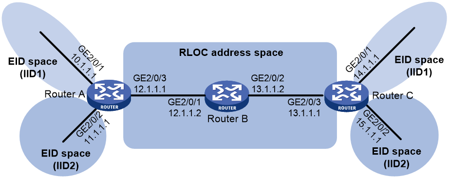
As shown in Figure 6, after LISP is enabled on all devices, make sure the following requirements are met:
· Router A and Router C are configured as xTRs.
· The MR and MS features are enabled on Router B.
· Two LISP VRF instances are created to route traffic from different tenants.
Procedure
1. Configure IP addresses for interfaces and create VPN instances. (Details not shown.)
2. Associate VPN instances with interfaces:
# Associate VPN instance 1, VPN instance 2, and VPN instance locator with GigabitEthernet 2/0/1, GigabitEthernet 2/0/2, and GigabitEthernet 2/0/3 of Router A, respectively.
<RouterA> system-view
[RouterA] interface gigabitethernet 2/0/1
[RouterA-GigabitEthernet2/0/1] ip binding vpn-instance 1
[RouterA-GigabitEthernet2/0/1] ip add 10.1.1.1 24
[RouterA-GigabitEthernet2/0/1] quit
[RouterA] interface gigabitethernet 2/0/2
[RouterA-GigabitEthernet2/0/2] ip binding vpn-instance 2
[RouterA-GigabitEthernet2/0/2] ip add 11.1.1.1 24
[RouterA-GigabitEthernet2/0/2] quit
[RouterA] interface gigabitethernet 2/0/3
[RouterA-GigabitEthernet2/0/3] ip binding vpn-instance locator
[RouterA-GigabitEthernet2/0/3] ip add 12.1.1.1 24
[RouterA-GigabitEthernet2/0/3] quit
# Associate VPN instance 1, VPN instance 2, and VPN instance locator with GigabitEthernet 2/0/1, GigabitEthernet 2/0/2, and GigabitEthernet 2/0/3 of Router C, respectively.
<RouterC> system-view
[RouterC] interface gigabitethernet 2/0/1
[RouterC-GigabitEthernet2/0/1] ip binding vpn-instance 1
[RouterC-GigabitEthernet2/0/1] ip add 14.1.1.1 24
[RouterC-GigabitEthernet2/0/1] quit
[RouterC] interface gigabitethernet 2/0/2
[RouterC-GigabitEthernet2/0/2] ip binding vpn-instance 2
[RouterC-GigabitEthernet2/0/2] ip add 15.1.1.1 24
[RouterC-GigabitEthernet2/0/2] quit
[RouterC] interface gigabitethernet 2/0/3
[RouterC-GigabitEthernet2/0/3] ip binding vpn-instance locator
[RouterC-GigabitEthernet2/0/3] ip add 13.1.1.1 24
[RouterC-GigabitEthernet2/0/3] quit
3. Configure LISP to support multiple instances:
# Configure Router A as an xTR and bind the IPv4 RLOC address space to the VRF instance locator.
[RouterA] lisp
[RouterA-lisp] vrf 1
[RouterA-lisp-vrf-1] itr
[RouterA-lisp-vrf-1] etr
[RouterA-lisp-vrf-1] locator-vrf vrf locator
# Assign the instance ID 1 to the EID prefixes in LISP VRF instance 1, configure a EID-to-RLOC mapping, and specify the MS and MR addresses.
[RouterA-lisp-vrf-1] xtr instance-id 1
[RouterA-lisp-vrf-1] database-mapping 10.1.1.0 24 12.1.1.1 priority 10 weight 10
[RouterA-lisp-vrf-1] itr map-resolver 12.1.1.2
[RouterA-lisp-vrf-1] etr map-server 12.1.1.2 authentication-mode sha-1 authentication-key plaintext abc
[RouterA-lisp-vrf-1] quit
# Configure Router A as an xTR and bind the IPv4 RLOC address space to the VRF instance locator.
[RouterA-lisp] vrf 2
[RouterA-lisp-vrf-2] itr
[RouterA-lisp-vrf-2] etr
[RouterA-lisp-vrf-2] locator-vrf vrf locator
# Assign the instance ID 2 to the EID prefixes in LISP VRF instance 2, configure a EID-to-RLOC mapping, and specify the MS and MR addresses.
[RouterA-lisp-vrf-2] xtr instance-id 2
[RouterA-lisp-vrf-2] database-mapping 11.1.1.0 24 12.1.1.1 priority 10 weight 10
[RouterA-lisp-vrf-2] itr map-resolver 12.1.1.2
[RouterA-lisp-vrf-2] etr map-server 12.1.1.2 authentication-mode sha-1 authentication-key plaintext abc
[RouterA-lisp-vrf-2] quit
# Enable the MS and MR features on Router B.
<RouterB> system-view
[RouterB] lisp
[RouterB-lisp] map-resolver
[RouterB-lisp] map-server
# Create LISP site 123, and permit the EID prefixes 10.1.1.0/24 and 14.1.1.0/24 with instance ID 1 and 11.1.1.0/24 and 15.1.1.0/24 with instance ID 2.
[RouterB-lisp] site 123
[RouterB-lisp-site-123] authentication-mode sha-1 authentication-key plaintext abc
[RouterB-lisp-site-123] eid-prefix 10.1.1.0 24 instance-id 1
[RouterB-lisp-site-123] eid-prefix 11.1.1.0 24 instance-id 2
[RouterB-lisp-site-123] eid-prefix 14.1.1.0 24 instance-id 1
[RouterB-lisp-site-123] eid-prefix 15.1.1.0 24 instance-id 2
# Configure Router C as an xTR and bind IPv4 RLOC address space to VPN instance locator.
[RouterC] lisp
[RouterC-lisp] vrf 1
[RouterC-lisp-vrf-1] itr
[RouterC-lisp-vrf-1] etr
[RouterC-lisp-vrf-1] locator-vrf vrf locator
# Assign the instance ID 1 to the EID prefixes in LISP VRF instance 1, configure a EID-to-RLOC mapping, and specify the MS and MR addresses.
[RouterC-lisp-vrf-1] xtr instance-id 1
[RouterC-lisp-vrf-1] database-mapping 14.1.1.0 24 13.1.1.1 priority 10 weight 10
[RouterC-lisp-vrf-1] itr map-resolver 12.1.1.2
[RouterC-lisp-vrf-1] etr map-server 12.1.1.2 authentication-mode sha-1 authentication-key plaintext abc
[RouterC-lisp-vrf-1] quit
# Configure Router C as an xTR and bind IPv4 RLOC address space to VPN instance locator.
[RouterC-lisp] vrf 2
[RouterC-lisp-vrf-2] itr
[RouterC-lisp-vrf-2] etr
[RouterC-lisp-vrf-2] locator-vrf vrf locator
# Assign the instance ID 2 to the EID prefixes in LISP VRF instance 2, configure a EID-to-RLOC mapping, and specify the MS and MR addresses.
[RouterC-lisp-vrf-2] xtr instance-id 2
[RouterC-lisp-vrf-2] database-mapping 15.1.1.0 24 13.1.1.1 priority 10 weight 10
[RouterC-lisp-vrf-2] itr map-resolver 12.1.1.2
[RouterC-lisp-vrf-2] etr map-server 12.1.1.2 authentication-mode sha-1 authentication-key plaintext abc
[RouterC-lisp-vrf-2] quit
Verifying the configuration
# Ping 14.1.1.1 with instance ID 1 from 10.1.1.1 on Router A.
[RouterA] ping –vpn-instance 1 –a 10.1.1.1 14.1.1.1
Ping 14.1.1.1 (14.1.1.1) from 10.1.1.1: 56 data bytes, press CTRL+C to break
Request time out
Request time out
56 bytes from 14.1.1.1: icmp_seq=2 ttl=254 time=1.582 ms
56 bytes from 14.1.1.1: icmp_seq=3 ttl=254 time=2.199 ms
56 bytes from 14.1.1.1: icmp_seq=4 ttl=254 time=1.976 ms
# Display IPv4 LISP mapping cache entries on Router A.
[RouterA] display lisp ipv4 map-cache
LISP IP Mapping Cache for VRF 1 (iid 1), 1 entries
14.1.1.0/24, uptime: 00:04:16, expires: 23:56:44, via map-reply
Locator Uptime State Priority/ Data Control
Weight in/out in/out
13.1.1.1 00:03:16 up 10/10 0/5 0/0
# Ping 15.1.1.1 with instance ID 2 from 11.1.1.1 on Router A.
[RouterA] ping –vpn-instance 2 –a 11.1.1.1 15.1.1.1
Ping 15.1.1.1 (15.1.1.1) from 11.1.1.1: 56 data bytes, press CTRL+C to break
Request time out
Request time out
56 bytes from 15.1.1.1: icmp_seq=2 ttl=254 time=1.582 ms
56 bytes from 15.1.1.1: icmp_seq=3 ttl=254 time=2.199 ms
56 bytes from 15.1.1.1: icmp_seq=4 ttl=254 time=1.976 ms
# Display IPv4 LISP mapping cache entries on Router A.
[RouterA] display lisp ipv4 map-cache
LISP IP Mapping Cache for VRF 2 (iid 2), 1 entries
15.1.1.0/24, uptime: 00:04:16, expires: 23:56:44, via map-reply
Locator Uptime State Priority/ Data Control
Weight in/out in/out
13.1.1.1 00:03:16 up 10/10 0/5 0/0
Example: Configuring LISP to support multiple xTRs
Network configuration
As shown in Figure 7, after LISP is enabled on all devices, make sure the following requirements are met:
· Router 1A and Router 2A are configured as xTRs to load share traffic from 10.1.1.0/24.
· Router 1C and Router 2C are configured as xTRs to load share traffic from 11.1.1.0/24.
· The MS and MR features are enabled on Router B.
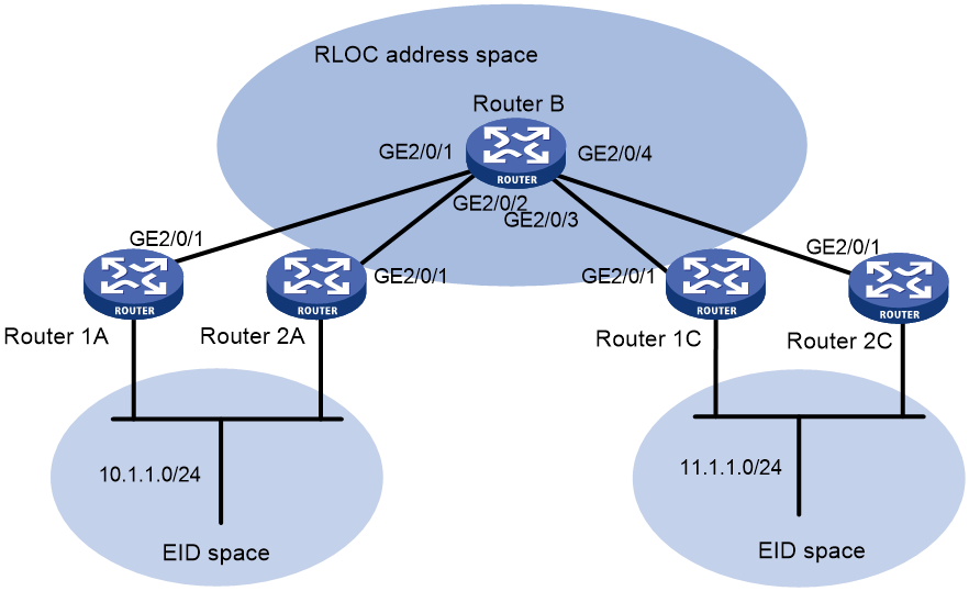
Table 1 Interface and IP address assignment
|
Device |
Interface |
IP address |
|
Router 1A |
GigabitEthernet 2/0/1 |
12.1.1.1/24 |
|
Router 2A |
GigabitEthernet 2/0/1 |
22.1.1.1/24 |
|
Router 1C |
GigabitEthernet 2/0/1 |
33.1.1.1/24 |
|
Router 2C |
GigabitEthernet 2/0/1 |
13.1.1.1/24 |
|
Router B |
GigabitEthernet 2/0/1 |
12.1.1.2/24 |
|
Router B |
GigabitEthernet 2/0/2 |
22.1.1.2/24 |
|
Router B |
GigabitEthernet 2/0/3 |
33.1.1.2/24 |
|
Router B |
GigabitEthernet 2/0/4 |
13.1.1.2/24 |
Procedure
1. Configure IP addresses for interfaces. (Details not shown.)
2. Configure the dynamic routing protocol to make sure the RLOC addresses are reachable. (Details not shown.)
3. Configure LISP:
# Configure Router 1A as an xTR.
<Router1A> system-view
[Router1A] lisp
[Router1A-lisp] itr
[Router1A-lisp] etr
[Router1A-lisp] database-mapping 10.1.1.0 24 12.1.1.1 priority 10 weight 10
[Router1A-lisp] database-mapping 10.1.1.0 24 22.1.1.1 priority 10 weight 10
[Router1A-lisp] itr map-resolver 12.1.1.2
[Router1A-lisp] itr map-resolver 22.1.1.2
[Router1A-lisp] etr map-server 12.1.1.2 authentication-mode sha-1 authentication-key plaintext abc
[Router1A-lisp] etr map-server 22.1.1.2 authentication-mode sha-1 authentication-key plaintext abc
[Router1A-lisp] quit
# Configure Router 2A as an xTR.
<Router2A> system-view
[Router2A] lisp
[Router2A-lisp] itr
[Router2A-lisp] etr
[Router2A-lisp] database-mapping 10.1.1.0 24 12.1.1.1 priority 10 weight 10
[Router2A-lisp] database-mapping 10.1.1.0 24 22.1.1.1 priority 10 weight 10
[Router2A-lisp] itr map-resolver 12.1.1.2
[Router2A-lisp] itr map-resolver 22.1.1.2
[Router2A-lisp] etr map-server 12.1.1.2 authentication-mode sha-1 authentication-key plaintext abc
[Router2A-lisp] etr map-server 22.1.1.2 authentication-mode sha-1 authentication-key plaintext abc
[Router2A-lisp] quit
# Enable the MS and MR features on Router B, create LISP site 123, and permit the EID prefixes 10.1.1.0/24 and 11.1.1.0/24 for registration.
[RouterB] lisp
[RouterB-lisp] map-resolver
[RouterB-lisp] map-server
[RouterB-lisp] site 123
[RouterB-lisp-site-123] authentication-mode sha-1 authentication-key plaintext abc
[RouterB-lisp-site-123] eid-prefix 10.1.1.0 24
[RouterB-lisp-site-123] eid-prefix 11.1.1.0 24
[RouterB-lisp-site-123] quit
[RouterB-lisp] quit
# Configure Router 1C as an xTR.
<Router1C> system-view
[Router1C] lisp
[Router1C-lisp] itr
[Router1C-lisp] etr
[Router1C-lisp] database-mapping 11.1.1.0 24 13.1.1.1 priority 10 weight 10
[Router1C-lisp] database-mapping 11.1.1.0 24 33.1.1.1 priority 10 weight 10
[Router1C-lisp] itr map-resolver 13.1.1.2
[Router1C-lisp] itr map-resolver 33.1.1.2
[Router1C-lisp] etr map-server 13.1.1.2 authentication-mode sha-1 authentication-key plaintext abc
[Router1C-lisp] etr map-server 33.1.1.2 authentication-mode sha-1 authentication-key plaintext abc
[Router1C-lisp] quit
# Configure Router 2C as an xTR.
<Router2C> system-view
[Router2C] lisp
[Router2C-lisp] itr
[Router2C-lisp] etr
[Router2C-lisp] database-mapping 11.1.1.0 24 13.1.1.1 priority 10 weight 10
[Router2C-lisp] database-mapping 11.1.1.0 24 33.1.1.1 priority 10 weight 10
[Router2C-lisp] itr map-resolver 13.1.1.2
[Router2C-lisp] itr map-resolver 33.1.1.2
[Router2C-lisp] etr map-server 13.1.1.2 authentication-mode sha-1 authentication-key plaintext abc
[Router2C-lisp] etr map-server 33.1.1.2 authentication-mode sha-1 authentication-key plaintext abc
[Router2C-lisp] quit
Verifying the configuration
# Ping 11.1.1.1 from 10.1.1.1 on Router 1A.
[Router1A] ping –a 10.1.1.1 11.1.1.1
Ping 11.1.1.1 (11.1.1.1) from 10.1.1.1: 56 data bytes, press CTRL+C to break
Request time out
Request time out
56 bytes from 11.1.1.1: icmp_seq=2 ttl=254 time=1.582 ms
56 bytes from 11.1.1.1: icmp_seq=3 ttl=254 time=2.199 ms
56 bytes from 11.1.1.1: icmp_seq=4 ttl=254 time=1.976 ms
# Display IPv4 LISP mapping cache entries on Router 1A.
[Router1A] display lisp ipv4 map-cache
LISP IP Mapping Cache for Public VRF (iid 0), 1 entries
11.1.1.0/24, uptime: 00:04:16, expires: 23:56:44, via map-reply
Locator Uptime State Priority/ Data Control
Weight in/out in/out
13.1.1.1 00:03:16 up 10/10 0/5 0/0
33.1.1.1 00:03:16 up 10/10 0/0 0/0
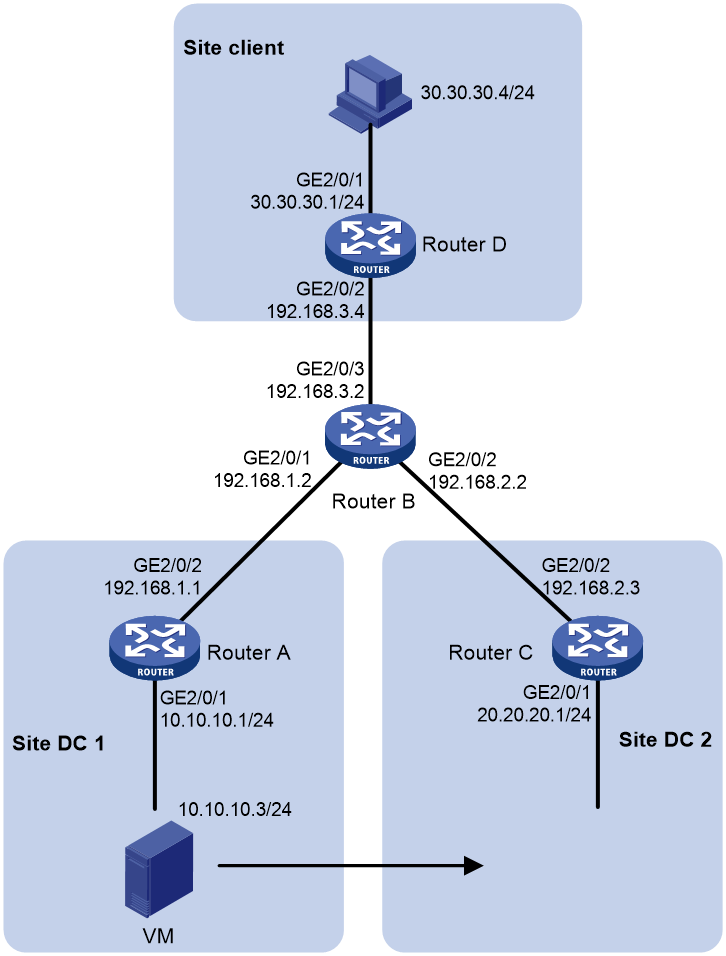
Example: Configuring virtual machine mobility across subnets
Network configuration
As shown in Figure 8, after LISP is enabled on all devices, make sure the following requirements are met:
· Router A, Router C, and Router D are configured as xTRs.
· The MR and MS features are enabled on Router B.
· Implement virtual machine mobility across subnets without changing the VM's IP address.
Procedure
1. Configure IP addresses for interfaces. (Details not shown.)
2. Configure the dynamic routing protocol to make sure the RLOC addresses are reachable. (Details not shown.)
3. Configure virtual machine mobility across subnets:
# Configure Router A as an xTR, create the dynamic EID detection policy de1, and apply the policy to GigabitEthernet 2/0/1.
<RouterA> system-view
[RouterA] lisp
[RouterA-lisp] itr
[RouterA-lisp] etr
[RouterA-lisp] database-mapping 10.10.10.0 24 192.168.1.1 priority 1 weight 1
[RouterA-lisp] itr map-resolver 192.168.1.2
[RouterA-lisp] etr map-server 192.168.1.2 authentication-mode sha-1 authentication-key plaintext aaa
[RouterA-lisp] dynamic-eid de1
[RouterA-lisp-dynamic-eid-de1] database-mapping 10.10.10.0 24 192.168.1.1 priority 1 weight 1
[RouterA-lisp-dynamic-eid-de1] map-server 192.168.1.2 authentication-mode sha-1 authentication-key plaintext aaa
[RouterA-lisp-dynamic-eid-de1] interface gigabitethernet 2/0/1
[RouterA-GigabitEthernet2/0/1] lisp mobility de1
# Create IPv4 VRRP group 1 and enable proxy ARP on Router A.
[RouterA-GigabitEthernet2/0/1] vrrp vrid 1 virtual-ip 10.10.10.10
[RouterA-GigabitEthernet2/0/1] proxy-arp enable
[RouterA-GigabitEthernet2/0/1] quit
# Enable the MS and MR features on Router B.
<RouterB> system-view
[RouterB] lisp
[RouterB-lisp] map-server
[RouterB-lisp] map-resolver
# Create the LISP site DC on Router B, and permit 10.10.10.0/24, 20.20.20.0/24, and EID prefixes longer than 10.10.10.0/24 to register.
[RouterB-lisp] site DC
[RouterB-lisp-site-DC] eid-prefix 10.10.10.0 24 accept-more-specifics
[RouterB-lisp-site-DC] eid-prefix 20.20.20.0 24
[RouterB-lisp-site-DC] authentication-mode sha-1 authentication-key plaintext aaa
[RouterB-lisp-site-DC] quit
# Create the LISP site client on Router B, and permit the EID prefix 30.30.30.0/24 for registration.
[RouterB-lisp] site client
[RouterB-lisp-site-client] eid-prefix 30.30.30.0 24
[RouterB-lisp-site-client] authentication-mode sha-1 authentication-key plaintext aaa
[RouterB-lisp-site-client] quit
[RouterB-lisp] quit
# Configure Router C as an xTR, create the dynamic EID detection policy de1, and apply the policy to GigabitEthernet 2/0/1.
<RouterC> system-view
[RouterC-lisp] itr
[RouterC-lisp] etr
[RouterC-lisp] database-mapping 20.20.20.0 24 192.168.2.3 priority 1 weight 1
[RouterC-lisp] itr map-resolver 192.168.2.2
[RouterC-lisp] etr map-server 192.168.2.2 authentication-mode sha-1 authentication-key plaintext aaa
[RouterC-lisp] dynamic-eid de1
[RouterC-lisp-dynamic-eid-de1] database-mapping 10.10.10.0 24 192.168.2.3 priority 1 weight 1
[RouterC-lisp-dynamic-eid-de1] map-server 192.168.2.2 authentication-mode sha-1 authentication-key plaintext aaa
[RouterC-lisp-dynamic-eid-de1] interface gigabitethernet 2/0/1
[RouterC-GigabitEthernet2/0/1] lisp mobility de1
# Create IPv4 VRRP group 1 and enable proxy ARP on Router C.
[RouterC-GigabitEthernet2/0/1] vrrp vrid 1 virtual-ip 20.20.20.20
[RouterC-GigabitEthernet2/0/1] proxy-arp enable
[RouterC-GigabitEthernet2/0/1] quit
# Configure Router D as an xTR.
<RouterD> system-view
[RouterD] lisp
[RouterD-lisp] itr
[RouterD-lisp] etr
[RouterD-lisp] database-mapping 30.30.30.0 24 192.168.3.4 priority 1 weight 1
[RouterD-lisp] itr map-resolver 192.168.3.2
[RouterD-lisp] etr map-server 192.168.3.2 authentication-mode sha-1 authentication-key plaintext aaa
[RouterD-lisp] quit
# Display IPv4 LISP site information on Router B.
[RouterB] display lisp site
LISP Site Registration Information for public VRF
Site Name Last Actively Who last EID-prefix Inst
Registered Registered Registered ID
DC 00:00:41 yes 192.168.1.1 10.10.10.0/24-0 0
00:00:32 yes 192.168.2.3 20.20.20.0/24 0
client 00:00:25 yes 192.168.3.4 30.30.30.0/24 0
# Ping VM 10.10.10.3 in the LISP site DC 1 from Site client 30.30.30.4. The VM can be successfully pinged. (Details not shown.)
# Display IPv4 LISP mapping cache entries on Router D.
[RouterD] display lisp ipv4 map-cache
LISP IP Mapping Cache for Public VRF (iid 0), 1 entries
10.10.10.0/24, uptime: 01:48:31, expires: 22:11:29, via map-reply
Locator Uptime State Priority/ Data Control
Weight in/out in/out
192.168.1.1 01:48:31 up 1/1 6/7 1/0
Verifying the configuration
# Move VM 10.10.10.3 from LISP site DC 1 to LISP site DC 2. (Details not shown.)
# Display the detected LISP dynamic EIDs on Router C.
[RouterC] display lisp dynamic-eid verbose
LISP dynamic EID information for public VRF
Dynamic EID name: de1
Database-mapping EID-prefix: 10.10.10.0/24, instance-id: 0, LSBs: 0x00000001
Locator: 192.168.2.3, Priority: 1, Weight: 1
Uptime: 00:00:15, State: up, local
Registering more-specific dynamic-EIDs
Map servers: 192.168.2.2
Site-based multicast Map-Notify group: none configured
Roaming dynamic EIDs allowed: 0.0.0.0/0
Number of roaming dynamic EIDs discovered: 1
Last dynamic EID discovered: 10.10.10.3, 00:00:15 ago
Roaming dynamic EIDs:
10.10.10.3, GigabitEthernet2/0/1, uptime: 00:00:15
discovered by: ip packet reception
# Display IPv4 LISP site information on Router B.
[RouterB] display lisp site
LISP Site Registration Information for public VRF
Site Name Last Actively Who last EID-prefix Inst
Registered Registered Registered ID
DC 00:00:41 yes 192.168.1.1 10.10.10.0/24-1 0
00:00:32 yes 192.168.2.3 20.20.20.0/24 0
client 00:00:25 yes 192.168.3.4 30.30.30.0/24 0
# Ping VM 10.10.10.3 in the LISP site DC 2 from Site client 30.30.30.4. The VM can be successfully pinged. (Details not shown.)
# Display IPv4 LISP mapping cache entries on Router D.
[RouterD] display lisp ipv4 map-cache
LISP IP Mapping Cache for Public VRF (iid 0), 1 entries
10.10.10.0/24, uptime: 01:48:31, expires: 22:11:29, via map-reply
Locator Uptime State Priority/ Data Control
Weight in/out in/out
192.168.1.1 01:48:31 up 1/1 6/7 1/0
10.10.10.3/32, uptime: 01:48:31, expires: 22:11:29, via map-reply
Locator Uptime State Priority/ Data Control
Weight in/out in/out
192.168.2.3 00:01:31 up 1/1 3/3 1/0
