- Table of Contents
-
- 12-Security Configuration Guide
- 00-Preface
- 01-Security zone configuration
- 02-AAA configuration
- 03-802.1X configuration
- 04-MAC authentication configuration
- 05-Portal configuration
- 06-Port security configuration
- 07-User profile configuration
- 08-Password control configuration
- 09-Keychain configuration
- 10-Public key management
- 11-PKI configuration
- 12-IPsec configuration
- 13-Group domain VPN configuration
- 14-SSH configuration
- 15-SSL configuration
- 16-SSL VPN configuration
- 17-ASPF configuration
- 18-APR configuration
- 19-Session management
- 20-Connection limit configuration
- 21-Object group configuration
- 22-Object policy configuration
- 23-Attack detection and prevention configuration
- 24-IP source guard configuration
- 25-ARP attack protection configuration
- 26-ND attack defense configuration
- 27-uRPF configuration
- 28-Crypto engine configuration
- 29-FIPS configuration
- 30-mGRE configuration
- Related Documents
-
| Title | Size | Download |
|---|---|---|
| 05-Portal configuration | 1.73 MB |
Contents
Configuring portal authentication
Advantages of portal authentication
Portal authentication using a remote portal server
MAC-based quick portal authentication
Portal authentication configuration in wireless networks
Restrictions: Hardware compatibility with portal authentication
Restrictions and guidelines: Portal configuration
Portal authentication tasks at a glance
Prerequisites for portal authentication
Configuring a remote portal authentication server
Configuring a portal Web server
Portal Web server tasks at a glance
Configure basic parameters for a portal Web server
Enabling the captive-bypass feature
Configuring a match rule for URL redirection
Configuring the URL and the type for portal Web server detection
Configuring the local portal service features
About the local portal service
Restrictions and guidelines for configuring local portal service features
Customizing authentication pages
Configuring a local portal Web service
Configuring the User-Agent match string
Enabling portal authentication on an interface
Specifying a portal Web server on an interface
Enabling portal authentication on a service template
Specifying a portal Web server on a service template
Configuring a portal preauthentication domain
Specifying a preauthentication IP address pool
Specifying a portal authentication domain
About portal authentication domains
Restrictions and guidelines for specifying a portal authentication domain
Specifying a portal authentication domain on an interface
Specifying an IPv4 portal authentication domain on a service template
Controlling portal user access
Configuring a portal-free rule
Configuring an authentication source subnet
Configuring an authentication destination subnet
Configuring a portal-forbidden rule
Enabling validity check on wireless clients
Setting the maximum number of portal users
Enabling strict-checking on portal authorization information
Allowing only users with DHCP-assigned IP addresses to pass portal authentication
Configuring support of portal authentication for dual stack
Enabling outgoing packets filtering
Configuring the portal fail-permit feature
Configuring portal detection features
Configuring online detection of portal users
Configuring portal authentication server detection
Configuring portal Web server detection
Configuring portal user synchronization
Configuring portal packet attributes
Configuring the BAS-IP or BAS-IPv6 attribute
Configuring attributes for RADIUS packets
Specifying a format for the NAS-Port-Id attribute
Applying a NAS-ID profile to an interface
Configuring the NAS-Port-Type attribute
Configuring MAC-based quick portal authentication
Restrictions and guidelines for configuring MAC-based quick portal authentication
Configuring a MAC binding server
Specifying a MAC binding server on an interface
Specifying a MAC binding server on a service template
Configure cloud MAC-trigger authentication
Setting the user traffic backup threshold
Disabling the Rule ARP or ND entry feature for portal clients
Disabling traffic accounting for portal users
Configuring Web redirect on an interface
Configuring Web redirect on a service template
Configuring portal safe-redirect
Setting the interval at which an AP reports traffic statistics to the AC
Excluding an attribute from portal protocol packets
Configuring support of portal authentication for third-party authentication
About third-party authentication
Restrictions and guidelines for third-party authentication
Editing buttons and pages for third-party authentication
Configuring email authentication
Configuring WeChat authentication
Configuring Facebook authentication
Specifying an authentication domain for third-party authentication
Specifying the AC's interface for portal clients to access during third-party authentication
Configuring portal temporary pass
Setting the user synchronization interval for portal authentication using OAuth
Configuring the portal authentication monitoring feature
Logging out wireless portal users that switch SSIDs
Display and maintenance commands for portal
Portal configuration examples (on routers)
Example: Configuring direct portal authentication
Example: Configuring re-DHCP portal authentication
Example: Configuring cross-subnet portal authentication
Example: Configuring extended direct portal authentication
Example: Configuring extended re-DHCP portal authentication
Example: Configuring extended cross-subnet portal authentication
Example: Configuring portal server detection and portal user synchronization
Example: Configuring cross-subnet portal authentication for MPLS L3VPNs
Example: Configuring direct portal authentication with a preauthentication domain
Example: Configuring re-DHCP portal authentication with a preauthentication domain
Example: Configuring direct portal authentication using a local portal Web service
Example: Configuring MAC-based quick portal authentication
Portal configuration examples (on ACs)
Example: Configuring direct portal authentication on a VLAN interface
Example: Configuring direct portal authentication on a service template
Example: Configuring extended direct portal authentication
Example: Configuring portal server detection
Example: Configuring direct portal authentication using a local portal Web service
Example: Configuring remote MAC-based quick portal authentication
Example: Configuring local MAC-based quick portal authentication
Example: Configuring cloud MAC-trigger authentication
Example: Configuring portal support for QQ authentication
Example: Configuring portal support for email authentication
Portal configuration examples (on fat APs)
Example: Configuring direct portal authentication
Example: Configuring extended direct portal authentication
Example: Configuring portal server detection and portal user synchronization
Example: Configuring direct portal authentication with a preauthentication domain
Example: Configuring direct portal authentication using a local portal Web service
No portal authentication page is pushed for users
Cannot log out portal users on the access device
Cannot log out portal users on the RADIUS server
Users logged out by the access device still exist on the portal authentication server
Re-DHCP portal authenticated users cannot log in successfully
Configuring portal authentication
About portal authentication
Portal authentication controls user access to networks. Portal authenticates a user by the username and password the user enters on a portal authentication page. Typically, portal authentication is deployed on the access layer and vital data entries.
In a portal-enabled network, users can actively initiate portal authentication by visiting the authentication website provided by the portal Web server. Or, they are redirected to the portal authentication page for authentication when they visit other websites.
The device supports Portal 1.0, Portal 2.0, and Portal 3.0.
Advantages of portal authentication
Portal authentication has the following advantages:
· Allows users to perform authentication through a Web browser without installing client software.
· Provides ISPs with diversified management choices and extended functions. For example, the ISPs can place advertisements, provide community services, and publish information on the authentication page.
· Supports multiple authentication modes. For example, re-DHCP authentication implements a flexible address assignment scheme and saves public IP addresses. Cross-subnet authentication can authenticate users who reside in a different subnet than the access device.
Extended portal functions
By forcing patching and anti-virus policies, extended portal functions help hosts to defend against viruses. Portal supports the following extended functions:
· Security check—Detects after authentication whether or not a user host installs anti-virus software, virus definition file, unauthorized software, and operating system patches.
· Resource access restriction—Allows an authenticated user to access certain network resources such as the virus server and the patch server. Users can access more network resources after passing security check.
Security check must cooperate with the H3C IMC security policy server and the iNode client.
Portal system
A typical portal system consists of these basic components: authentication client, access device, portal authentication server, portal Web server, AAA server, and security policy server.
Figure 1 Portal system
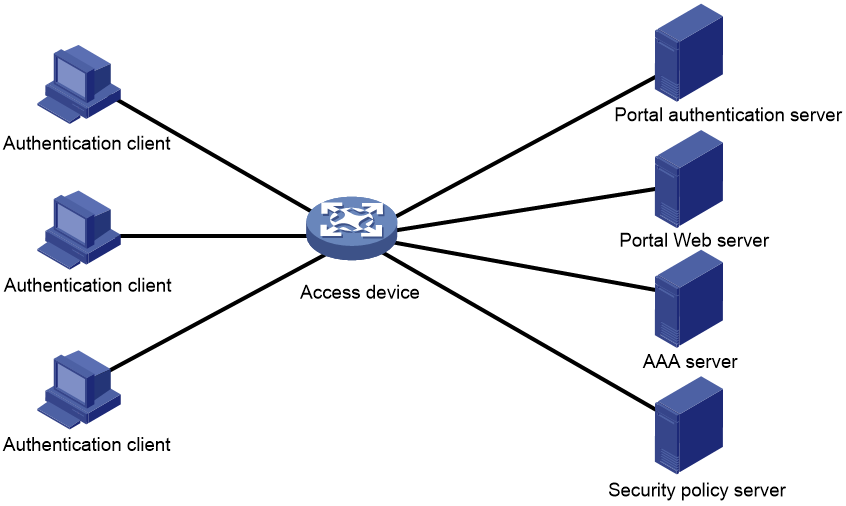
Authentication client
An authentication client is a Web browser that runs HTTP/HTTPS or a user host that runs a portal client. Security check for the user host is implemented through the interaction between the portal client and the security policy server. Only the H3C iNode client is supported.
Access device
An access device provides access services. It has the following functions:
· Redirects all HTTP or HTTPS requests of unauthenticated users to the portal Web server.
· Interacts with the portal authentication server and the AAA server to complete authentication, authorization, and accounting.
· Allows users that pass portal authentication to access authorized network resources.
Portal server
A portal server collectively refers to a portal authentication server and portal Web server.
The portal Web server pushes the Web authentication page to authentication clients and forwards user authentication information (username and password) to the portal authentication server. The portal authentication server receives authentication requests from authentication clients and interacts with the access device to authenticate users. The portal Web server is typically integrated with the portal authentication server and it can also be an independent server.
AAA server
The AAA server interacts with the access device to implement authentication, authorization, accounting for portal users. In a portal system, a RADIUS server can perform authentication, authorization, accounting for portal users, and an LDAP server can perform authentication for portal users.
Security policy server
The security policy server interacts with the portal client and the access device for security check and authorization for users. Only hosts that run portal clients can interact with the security policy server.
Portal authentication using a remote portal server
The components of a portal system interact as follows:
1. An unauthenticated user initiates authentication by accessing an Internet website through a Web browser. When receiving the HTTP or HTTPS request, the access device redirects it to the Web authentication page provided by the portal Web server. The user can also visit the authentication website to log in. The user must log in through the H3C iNode client for extended portal functions.
2. The user enters the authentication information on the authentication page/dialog box and submits the information. The portal Web server forwards the information to the portal authentication server. The portal authentication server processes the information and forwards it to the access device.
3. The access device interacts with the AAA server to implement authentication, authorization, accounting for the user.
4. If security policies are not imposed on the user, the access device allows the authenticated user to access networks.
If security policies are imposed on the user, the portal client, the access device, and the security policy server interact to check the user host. If the user passes the security check, the security policy server authorizes the user to access resources based on the check result.
Local portal service
System components
As shown in Figure 2, a local portal system consists of an authentication client, access device, and AAA server. The access device acts as both the portal Web server and the portal authentication server to provide the local portal Web service for the authentication client. The authentication client can only be a Web browser, and it cannot be a user host that runs a portal client. Therefore, extended portal functions are not supported and no security policy server is required.

Portal page customization
To provide the local portal web service, you must customize a set of authentication pages that the device will push to users. You can customize multiple sets of authentication pages, compress each set of the pages to a .zip file, and upload the compressed files to the storage medium of the device. On the device, you must specify one of the files as the default authentication page file by using the default-logon-page command.
For more information about authentication page customization, see "Customizing authentication pages."
Portal authentication modes
Portal authentication has three modes: direct authentication, re-DHCP authentication, and cross-subnet authentication. In direct authentication and re-DHCP authentication, no Layer 3 forwarding devices exist between the authentication client and the access device. In cross-subnet authentication, Layer 3 forwarding devices can exist between the authentication client and the access device.
Direct authentication
A user manually configures a public IP address or obtains a public IP address through DHCP. Before authentication, the user can access only the portal Web server and predefined authentication-free websites. After passing authentication, the user can access other network resources. The process of direct authentication is simpler than that of re-DHCP authentication.
Re-DHCP authentication
Before a user passes authentication, DHCP allocates an IP address (a private IP address) to the user. The user can access only the portal Web server and predefined authentication-free websites. After the user passes authentication, DHCP reallocates an IP address (a public IP address) to the user. The user then can access other network resources. No public IP address is allocated to users who fail authentication. Re-DHCP authentication saves public IP addresses. For example, an ISP can allocate public IP addresses to broadband users only when they access networks beyond the residential community network.
Only the H3C iNode client supports re-DHCP authentication. IPv6 portal authentication does not support the re-DHCP authentication mode.
Cross-subnet authentication
Cross-subnet authentication is similar to direct authentication, except it allows Layer 3 forwarding devices to exist between the authentication client and the access device.
In direct authentication, re-DHCP authentication, and cross-subnet authentication, a user's IP address uniquely identifies the user. After a user passes authentication, the access device generates an ACL for the user based on the user's IP address to control forwarding of the packets from the user. Because no Layer 3 forwarding device exists between authentication clients and the access device in direct authentication and re-DHCP authentication, the access device can learn the user MAC addresses. The access device can enhance its capability of controlling packet forwarding by using the learned MAC addresses.
Portal authentication process
Direct authentication and cross-subnet authentication share the same authentication process. Re-DHCP authentication has a different process as it has two address allocation procedures.
Direct authentication/cross-subnet authentication process (with CHAP/PAP authentication)
Figure 3 Direct authentication/cross-subnet authentication process
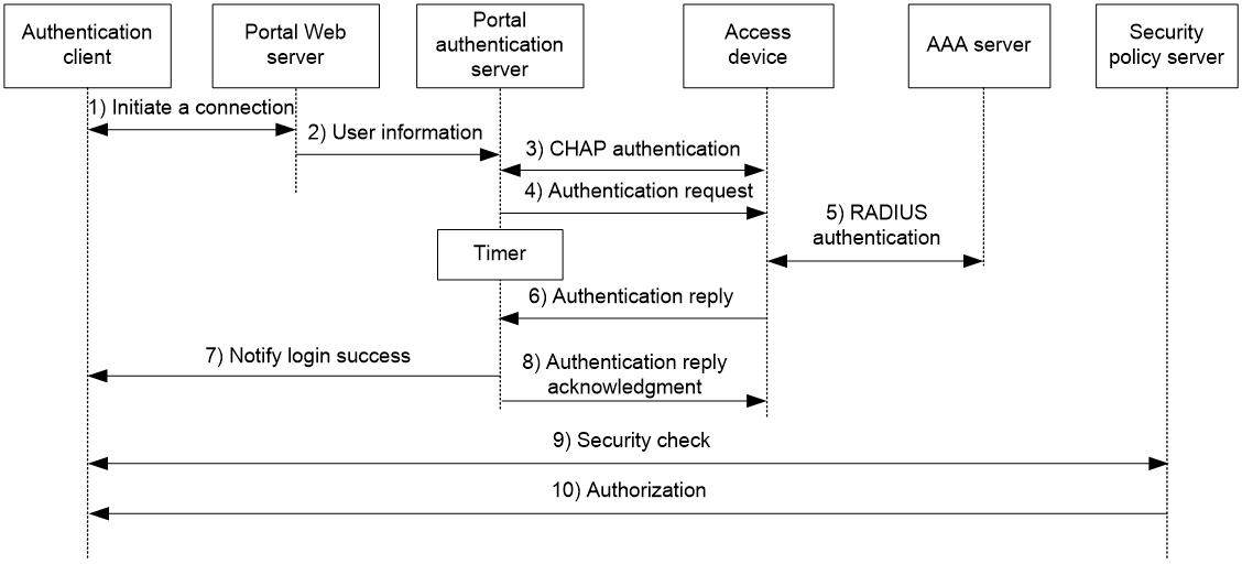
The direct/cross-subnet authentication process is as follows:
1. A portal user access the Internet through HTTP or HTTPS, and the HTTP or HTTPS packet arrives at the access device.
¡ If the packet matches a portal free rule, the access device allows the packet to pass.
¡ If the packet does not match any portal-free rule, the access device redirects the packet to the portal Web server. The portal Web server pushes the Web authentication page to the user for him to enter his username and password.
2. The portal Web server submits the user authentication information to the portal authentication server.
3. The portal authentication server and the access device exchange CHAP messages. This step is skipped for PAP authentication. The portal authentication server decides the method (CHAP or PAP) to use.
4. The portal authentication server adds the username and password into an authentication request packet and sends it to the access device. Meanwhile, the portal authentication server starts a timer to wait for an authentication reply packet.
5. The access device and the RADIUS server exchange RADIUS packets.
6. The access device sends an authentication reply packet to the portal authentication server to notify authentication success or failure.
7. The portal authentication server sends an authentication success or failure packet to the client.
8. If the authentication is successful, the portal authentication server sends an authentication reply acknowledgment packet to the access device.
If the client is an iNode client, the authentication process includes step 9 and step 10 for extended portal functions. Otherwise the authentication process is complete.
9. The client and the security policy server exchange security check information. The security policy server detects whether or not the user host installs anti-virus software, virus definition files, unauthorized software, and operating system patches.
10. The security policy server authorizes the user to access certain network resources based on the check result. The access device saves the authorization information and uses it to control access of the user.
Re-DHCP authentication process (with CHAP/PAP authentication)
Figure 4 Re-DHCP authentication process
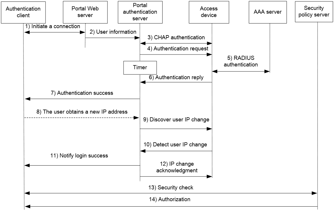
The re-DHCP authentication process is as follows:
Step 1 through step 7 are the same as those in the direct authentication/cross-subnet authentication process.
8. After receiving the authentication success packet, the client obtains a public IP address through DHCP. The client then notifies the portal authentication server that it has a public IP address.
9. The portal authentication server notifies the access device that the client has obtained a public IP address.
10. The access device detects the IP change of the client through DHCP and then notifies the portal authentication server that it has detected an IP change of the client IP.
11. After receiving the IP change notification packets sent by the client and the access device, the portal authentication server notifies the client of login success.
12. The portal authentication server sends an IP change acknowledgment packet to the access device.
Step 13 and step 14 are for extended portal functions.
13. The client and the security policy server exchanges security check information. The security policy server detects whether or not the user host installs anti-virus software, virus definition files, unauthorized software, and operating system patches.
14. The security policy server authorizes the user to access certain network resources based on the check result. The access device saves the authorization information and uses it to control access of the user.
Portal support for EAP
To use portal authentication that supports EAP, the portal authentication server and client must be the H3C IMC portal server and the H3C iNode portal client. Local portal authentication does not support EAP authentication.
Compared with username and password based authentication, digital certificate-based authentication ensures higher security.
The Extensible Authentication Protocol (EAP) supports several digital certificate-based authentication methods, for example, EAP-TLS. Working together with EAP, portal authentication can implement digital certificate-based user authentication.
Figure 5 Portal support for EAP working flow diagram
![]()
As shown in Figure 5, the authentication client and the portal authentication server exchange EAP authentication packets. The portal authentication server and the access device exchange portal authentication packets that carry the EAP-Message attributes. The access device and the RADIUS server exchange RADIUS packets that carry the EAP-Message attributes. The RADIUS server that supports the EAP server function processes the EAP packets encapsulated in the EAP-Message attributes, and provides the EAP authentication result.
The access device does not process but only transports EAP-Message attributes between the portal authentication server and the RADIUS server. Therefore, the access device requires no additional configuration to support EAP authentication.
Portal filtering rules
The access device uses portal filtering rules to control user traffic forwarding.
Based on the configuration and authentication status of portal users, the device generates the following categories of portal filtering rules:
· First category—The rule permits user packets that are destined for the portal Web server and packets that match the portal-free rules to pass through.
· Second category—For an authenticated user with no ACL authorized, the rule allows the user to access any destination network resources. For an authenticated user with an ACL authorized, the rule allows users to access resources permitted by the ACL. The device adds the rule when a user comes online and deletes the rule when the user goes offline.
The device supports the following types of authorization ACLs:
¡ Basic ACLs (ACL 2000 to ACL 2999).
¡ Advanced ACLs (ACL 3000 to ACL 3999).
¡ Layer 2 ACLs (ACL 4000 to ACL 4999).
For an authorization ACL to take effect, make sure the ACL exists and has ACL rules excluding rules configured with the counting, established, fragment, source-mac, or logging keyword. For more information about ACL rules, see ACL commands in ACL and QoS Command Reference.
· Third category—The rule redirects all HTTP or HTTPS requests from unauthenticated users to the portal Web server.
· Fourth category—For direct authentication and cross-subnet authentication, the rule forbids any user packets to pass through. For re-DHCP authentication, the device forbids user packets with private source addresses to pass.
After receiving a user packet, the device compares the packet against the filtering rules from the first category to the fourth category. Once the packet matches a rule, the matching process completes.
Portal support for BYOD
The BYOD feature must work with the IMC server.
During portal authentication, the device encapsulates obtained DHCP Option 55 information into portal and RADIUS packets and then uploads them to the UAM component of the IMC server.
Based on DHCP Option 55 information, UAM identifies the endpoint type, OS, and vendor information. UAM pushes different authentication pages and deploys different authorization information to different endpoints.
MAC-based quick portal authentication
MAC-based quick portal authentication is applicable to scenarios where users access the network frequently. It allows users to pass authentication without entering a username and password. MAC-based quick portal authentication is also called MAC-trigger authentication or transparent portal authentication.
A MAC binding server is required for MAC-trigger authentication. The MAC binding server records the MAC-to-account bindings of portal users for authentication. The account contains the portal authentication information of the user, including username and password.
Only IPv4 direct authentication supports MAC-based quick portal authentication.
The authentication is implemented as follows:
1. When a user accesses the network for the first time, the access device generates a MAC-trigger entry that records the user's MAC address and access interface. The user can access the network without performing portal authentication if the user's network traffic is below the free-traffic threshold.
2. When the user's network traffic reaches the threshold, the access device sends a MAC binding query to the MAC binding server.
3. The MAC binding server checks whether the MAC address of the user is bound with a portal user account.
¡ If a matching MAC-account binding exists, the MAC binding server sends the user authentication information to the access device to initiate portal authentication. The user is authenticated without entering the username and password.
- If the user fails portal authentication, an authentication failure message is returned to the user. The MAC-trigger entry of the user on the access device is deleted when the entry ages out.
- If the user passes portal authentication, the access device deletes the MAC-trigger entry of the user.
¡ If no matching MAC-account binding exists, the MAC binding server notifies the access device to perform normal portal authentication for the user.
- If the user fails portal authentication, an authentication failure message is returned to the user. The whole process is finished.
- If the user passes portal authentication, the access device sends the user's MAC address and authentication information to the MAC binding server for MAC-account binding. Additionally, the access device deletes the MAC-trigger entry of the user.
|
|
NOTE: · In wireless networks where APs are configured to forward client data traffic, APs report traffic statistics to the AC at regular intervals. The AC can determine whether a user's traffic exceeds the free-traffic threshold only after receiving the traffic statistics report from the associated AP. For information about setting the report interval, see "Setting the interval at which an AP reports traffic statistics to the AC." · For information about MAC binding server configuration, see the user manual of the server. |
Portal authentication configuration in wireless networks
There are two forwarding modes for client data in a fit AP+AC network:
· Centralized forwarding—The AP sends data frames from clients to the AC over the CAPWAP tunnel, and the AC forwards all data frames.
· Local forwarding—The AP directly forwards data frames from clients, instead of sending them to the AC for packet forwarding.
On the AC, you can configure portal authentication on a VLAN interface or a service template according to the client data forwarding mode.
· Portal authentication on a VLAN interface is applicable only in centralized forwarding mode.
The AC authenticates only the user packets that are received from the VLAN interface. In local forwarding mode, the AC cannot receive client data and, therefore, it cannot perform portal authentication for clients.
· Portal authentication on a service template is applicable in both centralized and local forwarding modes.
The AC deploys portal filtering rules to the BSS on this AC in centralized forwarding mode and to the BSS on an AP in local forwarding mode. The AC can authenticate users from all APs that are bound to the service template.
For more information about client traffic forwarding, see WLAN Configuration Guide.
Restrictions: Hardware compatibility with portal authentication
Only the following routers can function as ACs:
· MSR810, MSR810-W, MSR810-W-DB, MSR810-LM, MSR810-W-LM, MSR810-10-PoE, MSR810-LM-HK, MSR810-W-LM-HK, MSR810-LMS-EA.
· MSR2600-10-X1, MSR2600-6-X1.
· MSR 2630.
· MSR3600-28, MSR3600-51.
· MSR3600-28-X1, MSR3600-28-X1-DP, MSR3600-51-X1, MSR3600-51-X1-DP.
· MSR3610-I-DP, MSR3610-IE-DP.
· MSR3610-X1, MSR3610-X1-DP, MSR3610-X1-DC, MSR3610-X1-DP-DC.
· MSR 3610, MSR 3620, MSR 3620-DP, MSR 3640, MSR 3660.
Only the following routers can function as fat APs:
· MSR810-W.
· MSR810-W-DB.
· MSR810-W-LM.
· MSR810-W-LM-HK.
Restrictions and guidelines: Portal configuration
Portal authentication is supported only on Layer 3 interfaces.
The device can redirect HTTPS requests to the portal Web server for portal authentication. During SSL connection establishment, the user browser might display a message that it cannot verify server identity by certificate. For users to perform portal authentication without checking such a message, configure an SSL server policy to request a client-trusted certificate on the device. The name of the policy must be https_redirect. For information about SSL server policy configuration, see "Configuring SSL." For information about certificate request, see "Configuring PKI."
Portal authentication through Web does not support security check for users. To implement security check, the client must be the H3C iNode client.
Portal authentication supports NAT traversal whether it is initiated by a Web client or an H3C iNode client. NAT traversal must be configured when the portal client is on a private network and the portal server is on a public network.
Portal authentication tasks at a glance
To configure portal authentication, perform the following tasks:
1. Configuring a remote or local portal service as needed
¡ Configuring a remote portal service
Configuring a remote portal authentication server
Configuring a portal Web server
¡ Configuring a local portal service
Configuring the local portal service features
Configuring a portal Web server
2. Enabling portal authentication and specifying a portal Web server
Choose the options to configure on an interface or service template.
¡ Enabling portal authentication on an interface
¡ Specifying a portal Web server on an interface
¡ Enabling portal authentication on a service template
¡ Specifying a portal Web server on a service template
3. (Optional.) Configure parameters for preauthentication portal users
¡ Configuring a portal preauthentication domain
¡ Specifying a preauthentication IP address pool
4. (Optional.) Specifying a portal authentication domain
5. (Optional.) Controlling portal user access
¡ Configuring a portal-free rule
¡ Configuring an authentication source subnet
¡ Configuring an authentication destination subnet
¡ Configuring a portal-forbidden rule
¡ Enabling validity check on wireless clients
¡ Setting the maximum number of portal users
¡ Enabling strict-checking on portal authorization information
¡ Allowing only users with DHCP-assigned IP addresses to pass portal authentication
¡ Configuring support of portal authentication for dual stack
¡ Enabling outgoing packets filtering
¡ Configuring the portal fail-permit feature
6. (Optional.) Configuring portal detection features
¡ Configuring online detection of portal users
¡ Configuring portal authentication server detection
¡ Configuring portal Web server detection
¡ Configuring portal user synchronization
7. (Optional.) Configuring attributes for portal packets and RADIUS packets
¡ Configuring portal packet attributes
You can configure the BAS-IP or BAS-IPv6 attribute for portal packets and specify the device ID.
¡ Configuring attributes for RADIUS packets
You can configure the NAS-Port-Id attribute and the NAS-Port-Type attribute and apply a NAS-ID profile to an interface.
8. (Optional.) Configuring MAC-based quick portal authentication
a. Configuring a MAC binding server
b. Specifying a MAC binding server
Choose one of the following tasks:
Specifying a MAC binding server on an interface
Specifying a MAC binding server on a service template
c. Configure cloud MAC-trigger authentication
9. (Optional.) Configuring extended portal authentication features
¡ Setting the user traffic backup threshold
¡ Disabling the Rule ARP or ND entry feature for portal clients
¡ Disabling traffic accounting for portal users
¡ Configuring portal safe-redirect
¡ Setting the interval at which an AP reports traffic statistics to the AC
¡ Excluding an attribute from portal protocol packets
¡ Configuring support of portal authentication for third-party authentication
¡ Setting the user synchronization interval for portal authentication using OAuth
¡ Logging out wireless portal users that switch SSIDs
10. (Optional.) Monitoring portal authentication
¡ Configuring the portal authentication monitoring feature
Prerequisites for portal authentication
The portal feature provides a solution for user identity authentication and security check. To complete user identity authentication, portal must cooperate with RADIUS.
Before you configure portal, you must complete the following tasks:
· The portal authentication server, portal Web server, and RADIUS server have been installed and configured correctly.
· To use the re-DHCP portal authentication mode, make sure the DHCP relay agent is enabled on the access device, and the DHCP server is installed and configured correctly.
· The portal client, access device, and servers can reach each other.
· To use the remote RADIUS server, configure usernames and passwords on the RADIUS server, and configure the RADIUS client on the access device. For information about RADIUS client configuration, see "Configuring AAA."
· To implement extended portal functions, install and configure CAMS EAD or IMC EAD. Make sure the ACLs configured on the access device correspond to the isolation ACL and the security ACL on the security policy server. For information about security policy server configuration on the access device, see "Configuring AAA." For installation and configuration about the security policy server, see CAMS EAD Security Policy Component User Manual or IMC EAD Security Policy Help.
Configuring a remote portal authentication server
About configuring the remote portal authentication server
With portal authentication enabled, the device searches for a portal authentication server for a received portal request packet according to the source IP address and VPN instance information of the packet.
· If a matching portal authentication server is found, the device regards the packet valid and sends an authentication response packet to the portal authentication server. After a user logs in to the device, the user interacts with the portal authentication server as needed.
· If no matching portal authentication server is found, the device drops the packet.
Restrictions and guidelines
Do not delete a portal authentication server in use. Otherwise, users authenticated by that server cannot log out correctly.
Procedure
1. Enter system view.
system-view
2. Create a portal authentication server and enter its view.
portal server server-name
You can create multiple portal authentication servers.
3. Specify the IP address of the portal authentication server.
ip ipv4-address [ vpn-instance vpn-instance-name ] [ key { cipher | simple } string ]
IPv6:
ipv6 ipv6-address [ vpn-instance vpn-instance-name ] [ key { cipher | simple } string ]
4. (Optional.) Set the destination UDP port number used by the device to send unsolicited portal packets to the portal authentication server.
port port-number
By default, the UDP port number is 50100.
This port number must be the same as the listening port number specified on the portal authentication server.
5. (Optional.) Specify the portal authentication server type.
server-type { cmcc | imc }
By default, the portal authentication server type is IMC.
The specified server type must be the same as the type of the portal authentication server actually used.
6. (Optional.) Set the maximum number of times and the interval for retransmitting a logout notification packet.
logout-notify retry retries interval interval
By default, the device does not retransmit a logout notification packet.
7. (Optional.) Configure the device to periodically register with the portal authentication server.
server-register [ interval interval-value ]
By default, the device does not register with a portal authentication server.
Configuring a portal Web server
Portal Web server tasks at a glance
To configure a portal Web server, perform the following tasks:
1. Configure basic parameters for a portal Web server
2. (Optional.) Enabling the captive-bypass feature
3. (Optional.) Configuring a match rule for URL redirection
4. (Optional.) Configuring the URL and the type for portal Web server detection
Configure basic parameters for a portal Web server
1. Enter system view.
system-view
2. Create a portal Web server and enter its view.
portal web-server server-name
You can create multiple portal Web servers.
3. Specify the VPN instance to which the portal Web server belongs.
vpn-instance vpn-instance-name
By default, the portal Web server belongs to the public network.
4. Specify the URL of the portal Web server.
url url-string
By default, no URL is specified for a portal Web server.
5. Configure the parameters to be carried in the URL when the device redirects it to users.
url-parameter param-name { nas-id | nas-port-id | original-url | source-address | ssid | { ap-mac | source-mac } [ format section { 1 | 3 | 6 } { lowercase | uppercase } ] [ encryption { aes | des } key { cipher | simple } string ] | value expression | vlan }
By default, no redirection URL parameters are configured.
6. (Optional.) Specify the portal Web server type.
server-type { cmcc | imc | oauth }
By default, the portal Web server type is IMC.
This configuration is applicable to only to the remote portal service.
The specified server type must be the same as the type of the portal Web server actually used.
Enabling the captive-bypass feature
About the captive-bypass feature
Typically, when iOS mobile devices or some Android mobile devices are connected a portal-enabled network, the device pushes the authentication page to the mobile devices.
The captive-bypass feature enables the device to push the portal authentication page to the iOS and Android devices only when the users access the Internet by using a browser. If the users do not perform authentication but press the home button to return to the desktop, the Wi-Fi connection is terminated. To maintain the Wi-Fi connection in such cases, you can enable the optimized captive-bypass feature.
When optimized captive-bypass is enabled, the portal authentication page is automatically pushed to iOS mobile devices after they connects to the network. Users can perform authentication on the page or press the home button to return to the desktop without performing authentication, and the Wi-Fi connection is not terminated.
When the network condition is poor, the device cannot detect a server reachability detection packet from an iOS mobile client within the captive-bypass detection timeout time. The client cannot receive a response for the server reachability detection packet, and therefore it determines the server to be unreachable and terminates the Wi-Fi connection. To avoid Wi-Fi disconnections caused by server reachability detection failure, set a longer captive-bypass detection timeout time when the network condition is poor.
Procedure
1. Enter system view.
system-view
2. Enter portal Web server view.
portal web-server server-name
3. Enable the captive-pass feature.
captive-bypass [ android | ios [ optimize ] ] enable
By default, the captive-bypass feature is disabled. The device automatically pushes the portal authentication page to iOS mobile devices and some Android mobile devices when they are connected to a portal-enabled network.
4. (Optional.) Set the captive-bypass detection timeout time.
a. Return to system view.
quit
b. Set the captive-bypass detection timeout time.
portal captive-bypass optimize delay seconds
By default, the captive-bypass detection timeout time is 6 seconds.
Configuring a match rule for URL redirection
About match rules for URL redirection
A URL redirection match rule matches HTTP or HTTPS requests by user-requested URL or User-Agent information, and redirects the matching HTTP or HTTPS requests to the specified redirection URL.
For a portal Web server, you can configure the url command and the if-match command for URL redirection. The url command redirects all HTTP or HTTPS requests from unauthenticated users to the portal Web server for authentication. The if-match command allows for flexible URL redirection by redirecting specific HTTP or HTTPS requests to specific redirection URLs.
Restrictions and guidelines
For a user to successfully access a redirection URL, configure a portal-free rule to allow HTTP or HTTPS requests destined for the redirection URL to pass. For information about configuring portal-free rules, see the portal free-rule command.
If both the url and if-match commands are executed, the if-match command takes priority to perform URL redirection.
Procedure
1. Enter system view.
system-view
2. Enter portal Web server view.
portal web-server server-name
3. Configure a match rule for URL redirection.
if-match { original-url url-string redirect-url url-string [ url-param-encryption { aes | des } key { cipher | simple } string ] | user-agent string redirect-url url-string }
Configuring the URL and the type for portal Web server detection
1. Enter system view.
system-view
2. Enter portal Web server view.
portal web-server server-name
3. Configure the URL and the type for portal Web server detection.
server-detect url string [ detect-type { http | tcp } ]
Configuring the local portal service features
About the local portal service
After a local portal service is configured, the device acts as the portal Web server and portal authentication server to perform portal authentication on users. The portal authentication page file is saved in the root directory of the device.
Restrictions and guidelines for configuring local portal service features
For an interface to use the local portal service, the URL of the portal Web server specified for the interface must meet the following requirements:
· The IP address in the URL must be the IP address of a Layer 3 interface (except 127.0.0.1) on the device, and the IP address must be reachable to portal clients.
· The URL must be ended with /portal/. For example: http://1.1.1.1/portal/.
You must customize the authentication pages and upload them to the device.
In wireless networks, you can bind different authentication pages for portal users that belong to different SSIDs and use different device types (such as iPhone and Samsung). The system selects the authentication pages in the following order:
1. Authentication pages bound to the SSID or device type.
2. Default authentication pages.
Customizing authentication pages
About customizing authentication pages
Authentication pages are HTML files. Local portal authentication requires the following authentication pages:
· Logon page
· Logon success page
· Logon failure page
· Online page
· System busy page
· Logoff success page
You must customize the authentication pages, including the page elements that the authentication pages will use, for example, back.jpg for authentication page Logon.htm.
Follow the authentication page customization rules when you edit the authentication page files.
File name rules
The names of the main authentication page files are fixed (see Table 1). You can define the names of the files other than the main authentication page files. File names and directory names are case insensitive.
Table 1 Main authentication page file names
|
Main authentication page |
File name |
|
Logon page |
logon.htm |
|
Logon success page |
logonSuccess.htm |
|
Logon failure page |
logonFail.htm |
|
Online page Pushed after the user gets online for online notification |
online.htm |
|
System busy page Pushed when the system is busy or the user is in the logon process |
busy.htm |
|
Logoff success page |
logoffSuccess.htm |
Page request rules
A local portal Web service supports only Get and Post requests.
· Get requests—Used to get the static files in the authentication pages and allow no recursion. For example, if file Logon.htm includes contents that perform Get action on file ca.htm, file ca.htm cannot include any reference to file Logon.htm.
· Post requests—Used when users submit username and password pairs, log in, and log out.
Post request attribute rules
1. Observe the following requirements when editing a form of an authentication page:
¡ An authentication page can have multiple forms, but there must be one and only one form whose action is logon.cgi. Otherwise, user information cannot be sent to the access device.
¡ The username attribute is fixed as PtUser. The password attribute is fixed as PtPwd.
¡ The value of the PtButton attribute is either Logon or Logoff, which indicates the action that the user requests.
¡ A logon Post request must contain PtUser, PtPwd, and PtButton attributes.
¡ A logoff Post request must contain the PtButton attribute.
2. Authentication pages logon.htm and logonFail.htm must contain the logon Post request.
The following example shows part of the script in page logon.htm.
<form action=logon.cgi method = post >
<p>User name:<input type="text" name = "PtUser" style="width:160px;height:22px" maxlength=64>
<p>Password :<input type="password" name = "PtPwd" style="width:160px;height:22px" maxlength=32>
<p><input type=SUBMIT value="Logon" name = "PtButton" style="width:60px;" onclick="form.action=form.action+location.search;">
</form>
3. Authentication pages logonSuccess.htm and online.htm must contain the logoff Post request.
The following example shows part of the script in page online.htm.
<form action=logon.cgi method = post >
<p><input type=SUBMIT value="Logoff" name="PtButton" style="width:60px;">
</form>
Page file compression and saving rules
You must compress the authentication pages and their page elements into a standard zip file.
· The name of a zip file can contain only letters, numbers, and underscores.
· The authentication pages must be placed in the root directory of the zip file.
· Zip files can be transferred to the device through FTP or TFTP and must be saved in the root directory of the device.
Examples of zip files on the device:
<Sysname> dir
Directory of flash:
1 -rw- 1405 Feb 28 2008 15:53:20 abc1.zip
0 -rw- 1405 Feb 28 2008 15:53:31 abc2.zip
2 -rw- 1405 Feb 28 2008 15:53:39 abc3.zip
3 -rw- 1405 Feb 28 2008 15:53:44 abc4.zip
2540 KB total (1319 KB free)
Redirecting authenticated users to a specific webpage
To make the device automatically redirect authenticated users to a specific webpage, do the following in logon.htm and logonSuccess.htm:
1. In logon.htm, set the target attribute of Form to _blank.
See the contents in gray:
<form method=post action=logon.cgi target="_blank">
2. Add the function for page loading pt_init() to LogonSuccess.htm.
See the contents in gray:
<html>
<head>
<title>LogonSuccess</title>
<script type="text/javascript" language="javascript" src="pt_private.js"></script>
</head>
<body onload="pt_init();" onbeforeunload="return pt_unload();">
... ...
</body>
</html>
Configuring a local portal Web service
Prerequisites
Before you configure an HTTPS-based local portal Web service, you must complete the following tasks:
· Configure a PKI policy, obtain the CA certificate, and request a local certificate. For more information, see "Configuring PKI."
· Configure an SSL server policy, and specify the PKI domain configured in the PKI policy.
During SSL connection establishment, the user browser might display a message that it cannot verify server identity by certificate. For users to perform portal authentication without checking such a message, configure an SSL server policy to request a client-trusted certificate on the device. The name of the policy must be https_redirect. For more information about SSL server policy configuration, see "Configuring SSL."
Procedure
1. Enter system view.
system-view
2. Create an HTTP- or HTTPS-based local portal Web service and enter its view.
portal local-web-server { http | https [ ssl-server-policy policy-name ] [ tcp-port port-number ] }
3. Specify the default authentication page file for the local portal Web service.
default-logon-page filename
By default, no default authentication page file is specified for the local portal Web service.
4. (Optional.) Configure the listening TCP port for the local portal Web service.
tcp-port port-number
By default, the HTTP service listening port number is 80 and the HTTPS service listening port number is the TCP port number set by the portal local-web-server command.
5. (Optional.) Bind an SSID or endpoint type to an authentication page file.
logon-page bind { device-type { computer | pad | phone } | device-name device-name | ssid ssid-name } * file file-name
By default, no SSID or endpoint type is bound to an authentication page file.
6. (Optional.) Enable local portal user password modification.
user-password modify enable
By default, local portal user password modification is disabled.
Configuring the User-Agent match string
About the User-Agent match string
When portal users use third-party software to perform portal authentication, the device checks the User-Agent string in portal authentication requests. If the User-Agent string does not include the match string specified on the device, users will fail portal authentication.
The User-Agent string includes hardware vendor, software operating system, browser, and search engine information. Perform this task to specify a string that can match the User-Agent information of the third-party software, so users can pass portal authentication by using that third-party software. For example, for users to pass portal authentication by following a WeChat official account, configure the User-Agent match string on the device as MicroMessenger.
Procedure
1. Enter system view.
system-view
2. Enter local portal Web service view.
portal local-web-server { http | https [ ssl-server-policy policy-name ] [ tcp-port port-number ] }
3. Configure the User-Agent match string.
user-agent user-agent-string
By default, the User-Agent match string is MicroMessenger.
Enabling portal authentication on an interface
Restrictions and guidelines
When you enable portal authentication on an interface, follow these restrictions and guidelines:
· For portal authentication to take effect on an Ethernet interface, do not add the Ethernet interface to an aggregation group.
· Do not enable portal authentication on both an interface and a service template.
· Cross-subnet authentication mode (layer3) does not require Layer 3 forwarding devices between the access device and the portal authentication clients. However, if a Layer 3 forwarding device exists between the authentication client and the access device, you must use the cross-subnet portal authentication mode.
· You can enable both IPv4 portal authentication and IPv6 portal authentication on an interface.
When you configure re-DHCP portal authentication on an interface, follow these restrictions and guidelines:
· Make sure the interface has a valid IP address before you enable re-DHCP portal authentication on the interface.
· With re-DHCP portal authentication, configure authorized ARP on the interface as a best practice to make sure only valid users can access the network. With authorized ARP configured on the interface, the interface learns ARP entries only from the users who have obtained a public address from DHCP.
· For successful re-DHCP portal authentication, make sure the BAS-IP or BAS-IPv6 attribute value is the same as the device IP address specified on the portal authentication server. To configure the attribute, use the portal { bas-ip | bas-ipv6 } command.
· An IPv6 portal server does not support re-DHCP portal authentication.
Procedure
1. Enter system view.
system-view
2. Enter Layer 3 interface view.
interface interface-type interface-number
3. Enable portal authentication.
IPv4:
portal enable method { direct | layer3 | redhcp }
IPv6:
portal ipv6 enable method { direct | layer3 }
By default, portal authentication is disabled.
Specifying a portal Web server on an interface
About specifying a portal Web server on an interface
With a portal Web server specified on an interface, the device redirects the HTTP requests of portal users on the interface to the portal Web server.
You can specify both an IPv4 portal Web server and an IPv6 portal Web server on an interface.
Procedure
1. Enter system view.
system-view
2. Enter Layer 3 interface view.
interface interface-type interface-number
3. Specify a portal Web server on the interface.
portal [ ipv6 ] apply web-server server-name [ secondary ]
By default, no portal Web servers are specified on an interface.
Enabling portal authentication on a service template
Restrictions and guidelines
Do not enable portal authentication on both an interface and a service template.
Only direct portal authentication is supported on a service template.
You can enable portal authentication for a service template only when the service template is disabled.
When local forwarding is used in wireless networks, enable validity check on wireless clients.
Procedure
1. Enter system view.
system-view
2. Enter service template view.
wlan service-template service-template-name
3. Enable direct portal authentication on the service template.
portal [ ipv6 ] enable method direct
By default, direct portal authentication is disabled on a service template.
Specifying a portal Web server on a service template
About specifying a portal Web server on a service template
With a portal Web server specified, the device redirects HTTP requests from portal users on WLAN-BSS interfaces bound to the specified service template to the specified portal Web server.
Restrictions and guidelines
You can specify a portal Web server on a service template only when the service template is disabled.
Procedure
1. Enter system view.
system-view
2. Enter service template view.
wlan service-template service-template-name
3. Specify a portal Web server on the service template.
portal [ ipv6 ] apply web-server server-name [ secondary ]
By default, no portal Web server is specified on a service template.
Configuring a portal preauthentication domain
About portal preauthentication domains
A portal preauthentication domain defines user attributes assigned to preauthentication portal users on a portal-enabled interface after the users obtain IP addresses. Before the preauthentication users pass portal authentication, they have limited access to the network based on the assigned user attributes (such as ACL, user profile, session group profile, and CAR). After the users pass portal authentication, they are assigned new attributes by the AAA server. After the users go offline, they are re-assigned user attributes in the preauthentication domain.
Restrictions and guidelines
The portal preauthentication domain takes effect only on portal users with IP addresses obtained through DHCP or DHCPv6.
The portal preauthentication domain does not take effect on interfaces enabled with cross-subnet portal authentication.
Make sure you specify an existing ISP domain as a portal preauthentication domain. If the specified ISP domain does not exist, the device might operate incorrectly.
You must delete a preauthentication domain (by using the undo portal [ ipv6 ] pre-auth domain command) and reconfigure it in the following situations:
· You create the ISP domain after specifying it as the preauthentication domain.
· You delete the specified ISP domain and then re-create it.
For the authorization ACL in the preauthentication domain, the following rules apply:
· If the traffic of preauthentication users matches a rule in the ACL, the device processes the traffic based on the permit or deny statement of the rule.
· If the ACL does not exist or the destination address permitted by a rule in the ACL is set to any, the device does not control user access. Users can access any network resources without passing portal authentication.
· If the ACL does not have any rules, the device allows users to access network resources only after the users pass authentication.
· If the traffic of preauthentication users does not match any rule in the ACL, the device pushes the authentication page to the users. The users can access the network resources after passing authentication.
· If the ACL contains rules that specify a source address, users might not be able to get online. Do not specify a source IPv4, IPv6, or MAC address when you configure a rule in the ACL.
Procedure
1. Enter system view.
system-view
2. Enter Layer 3 interface view.
interface interface-type interface-number
3. Specify a portal preauthentication domain.
portal [ ipv6 ] pre-auth domain domain-name
By default, no portal preauthentication domain is specified.
Specifying a preauthentication IP address pool
About preauthentication IP address pools
You must specify a preauthentication IP address pool on a portal-enabled interface in the following situation:
· Portal users access the network through a subinterface of the portal-enabled interface.
· The subinterface does not have an IP address.
· Portal users need to obtain IP addresses through DHCP.
After a user connects to a portal-enabled interface, the user uses an IP address for portal authentication according to the following rules:
· If the interface is configured with a preauthentication IP address pool, the user uses the following IP address:
¡ If the client is configured to obtain an IP address automatically through DHCP, the user obtains an address from the specified IP address pool.
¡ If the client is configured with a static IP address, the user uses the static IP address. However, if the interface does not have an IP address, users using static IP addresses cannot pass authentication.
· If the interface has an IP address but no preauthentication IP pool specified, the user uses the static IP address or the IP address obtained from a DHCP server.
· If the interface has no IP address or preauthentication IP pool specified, the user cannot perform portal authentication.
After the user passes portal authentication, the AAA server authorizes an IP address pool for re-assigning an IP address to the user. If no authorized IP address pool is deployed, the user continues using the previous IP address.
Restrictions and guidelines
This configuration takes effect only when the direct IPv4 portal authentication is enabled on the interface.
Make sure the specified IP address pool exists and is complete. Otherwise, the user cannot obtain the IP address and cannot perform portal authentication.
If the portal user does not perform authentication or fails to pass authentication, the assigned IP address is still retained.
Procedure
1. Enter system view.
system-view
2. Enter Layer 3 interface view.
interface interface-type interface-number
3. Specify a preauthentication IP address pool on the interface.
portal [ ipv6 ] pre-auth ip-pool pool-name
By default, no preauthentication IP address pool is specified on an interface.
Specifying a portal authentication domain
About portal authentication domains
An authentication domain defines a set of authentication, authorization, and accounting policies. Each portal user belongs to an authentication domain and is authenticated, authorized, and accounted in the domain.
With an authentication domain specified on an interface or service template, the device uses the authentication domain for AAA of portal users. This allows for flexible portal access control.
Restrictions and guidelines for specifying a portal authentication domain
The device selects the authentication domain for a portal user in this order:
1. ISP domain specified for the interface or service template.
2. ISP domain carried in the username.
3. System default ISP domain.
If the chosen domain does not exist on the device, the device searches for the ISP domain configured to accommodate users assigned to nonexistent domains. If no such ISP domain is configured, user authentication fails. For information about ISP domains, see "Configuring AAA."
If an authorization VPN instance is specified in the authentication domain, follow these restrictions and guidelines:
· Make sure the authorization VPN instance exists. If you specify a nonexistent VPN instance, users cannot come online.
· When users are online, do not delete the authorization VPN instance. Deleting the authorization VPN instance will log out the users.
For the authorization ACL in the authentication domain, the following rules apply:
· If the user traffic matches a rule in the ACL, the device processes the traffic based on the permit or deny statement of the rule.
· If the user traffic does not match any rule in the ACL, the device permits the traffic.
· If the ACL contains rules that specify a source address, users might not be able to get online. Do not specify a source IPv4, IPv6, or MAC address when you configure a rule in the ACL.
Specifying a portal authentication domain on an interface
1. Enter system view.
system-view
2. Enter Layer 3 interface view.
interface interface-type interface-number
3. Specify an portal authentication domain on the interface.
portal [ ipv6 ] domain domain-name
By default, no portal authentication domain is specified on an interface.
You can specify both an IPv4 portal authentication domain and an IPv6 portal authentication domain on an interface.
Specifying an IPv4 portal authentication domain on a service template
1. Enter system view.
system-view
2. Enter service template view.
wlan service-template service-template-name
3. Specify a portal authentication domain on the service template.
portal [ ipv6 ] domain domain-name
By default, no portal authentication domain is specified on a service template.
Controlling portal user access
Configuring a portal-free rule
About portal-free rules
A portal-free rule allows specified users to access specified external websites without portal authentication.
The matching items for a portal-free rule include the host name, source/destination IP address, TCP/UDP port number, source MAC address, access interface, and VLAN. Packets matching a portal-free rule will not trigger portal authentication, so users sending the packets can directly access the specified external websites.
Restrictions and guidelines for configuring a portal-free rule
If you specify both a VLAN and an interface, the interface must belong to the VLAN. If the interface does not belong to the VLAN, the portal-free rule does not take effect.
You cannot configure two or more portal-free rules with the same filtering criteria. Otherwise, the system prompts that the rule already exists.
Regardless of whether portal authentication is enabled or not, you can only add or remove a portal-free rule. You cannot modify it.
If portal users have come online before source-based portal-free rules are configured, the device keeps performing accounting on traffic of the users.
Configuring an IP-based portal-free rule
1. Enter system view.
system-view
2. Configure an IP-based portal-free rule.
IPv4:
portal free-rule rule-number { destination ip { ipv4-address { mask-length | mask } | any } [ tcp tcp-port-number | udp udp-port-number ] | source ip { ipv4-address { mask-length | mask } | any } [ tcp tcp-port-number | udp udp-port-number ] } * [ interface interface-type interface-number ]
IPv6:
portal free-rule rule-number { destination ipv6 { ipv6-address prefix-length | any } [ tcp tcp-port-number | udp udp-port-number ] | source ipv6 { ipv6-address prefix-length | any } [ tcp tcp-port-number | udp udp-port-number ] } * [ interface interface-type interface-number ]
By default, no IP-based portal-free rules are configured.
Configuring a source-based portal-free rule
1. Enter system view.
system-view
2. Configure a source-based portal-free rule.
portal free-rule rule-number source { ap ap-name | { interface interface-type interface-number | mac mac-address | object-group object-group-name | vlan vlan-id } * }
By default, no source-based portal-free rules are configured.
The vlan vlan-id option takes effect only on portal users that access the network through VLAN interfaces.
Configuring a destination-based portal-free rule
1. Enter system view.
system-view
2. Configure a destination-based portal-free rule.
portal free-rule rule-number destination host-name
By default, no destination-based portal-free rules are configured.
Configuring a description for a portal-free rule
1. Enter system view.
system-view
2. Configure a description for a portal-free rule.
portal free-rule rule-number description text
By default, no description is configured for a portal-free rule.
Configuring an authentication source subnet
About authentication source subnets
By configuring authentication source subnets, you specify that only HTTP or HTTPS packets from users on the authentication source subnets can trigger portal authentication. If an unauthenticated user is not on any authentication source subnet, the access device discards all the user's HTTP or HTTPS packets that do not match any portal-free rule.
Restrictions and guidelines
Authentication source subnets apply only to cross-subnet portal authentication.
In direct or re-DHCP portal authentication mode, a portal user and its access interface (portal-enabled) are on the same subnet. It is not necessary to specify the subnet as the authentication source subnet.
· In direct mode, the access device regards the authentication source subnet as any source IP address.
· In re-DHCP mode, the access device regards the authentication source subnet on an interface as the subnet to which the private IP address of the interface belongs.
If both authentication source subnets and destination subnets are configured on an interface, only the authentication destination subnets take effect.
You can configure multiple authentication source subnets. If the source subnets overlap, the subnet with the largest address scope (with the smallest mask or prefix) takes effect.
Procedure
1. Enter system view.
system-view
2. Enter Layer 3 interface view.
interface interface-type interface-number
3. Configure a portal authentication source subnet.
IPv4:
portal layer3 source ipv4-network-address { mask-length | mask }
By default, users from any subnets must pass portal authentication.
IPv6:
portal ipv6 layer3 source ipv6-network-address prefix-length
By default, users from any subnets must pass portal authentication.
Configuring an authentication destination subnet
About authentication destination subnets
By configuring authentication destination subnets, you specify that users trigger portal authentication only when they accessing the specified subnets (excluding the destination IP addresses and subnets specified in portal-free rules). Users can access other subnets without portal authentication.
Restrictions and guidelines
If both authentication source subnets and destination subnets are configured on an interface, only the authentication destination subnets take effect.
You can configure multiple authentication destination subnets. If the destination subnets overlap, the subnet with the largest address scope (with the smallest mask or prefix) takes effect.
Procedure
1. Enter system view.
system-view
2. Enter Layer 3 interface view.
interface interface-type interface-number
3. Configure a portal authentication destination subnet.
IPv4:
portal free-all except destination ipv4-network-address { mask-length | mask }
portal ipv6 free-all except destination ipv6-network-address prefix-length
By default, users accessing any subnets must pass portal authentication.
Configuring a portal-forbidden rule
About portal-forbidden rules
Portal-forbidden rules are used to filter user packets from the specified sources or destined for the specified destinations. The device drops HTTP or HTTPS packets that match the portal-forbidden rules.
Restrictions and guidelines
In a portal-forbidden rule, the source and destination IP addresses must be of the same IP type, and the source and destination ports must be of the same transport protocol type.
You can configure multiple portal-forbidden rules.
If the source or destination information in a portal-free rule and that in a portal-forbidden rule overlap, the portal-forbidden rule takes effect.
If you specify a destination host name in a portal-forbidden rule, the device drops users' DNS query packets for the specified host name. In addition, if a DNS server is correctly configured on the device, the device also drops user packets destined for the IP address resolved from the specified host name. If the DNS server is not correctly configured, the rule does not take effect on user packets destined for that IP address.
Procedure
1. Enter system view.
system-view
2. Configure a portal-forbidden rule.
IPv4:
portal forbidden-rule rule-number [ source { ip { ipv4-address { mask-length | mask } | any } [ tcp tcp-port-number | udp udp-port-number ] | ssid ssid-name } * ] destination { host-name | ip { ipv4-address { mask-length | mask } | any } [ tcp tcp-port-number | udp udp-port-number ] }
IPv6:
portal forbidden-rule rule-number [ source { ipv6 { ipv6-address prefix-length | any } [ tcp tcp-port-number | udp udp-port-number ] | ssid ssid-name } * ] destination { host-name | ipv6 { ipv6-address prefix-length | any } [ tcp tcp-port-number | udp udp-port-number ] }
By default, portal-forbidden rules are configured.
Enabling validity check on wireless clients
About validity check on wireless clients
Enable this feature when portal authentication is enabled on a service template. In wireless networks where the AP forwards client traffic, the AC does not have ARP entries for clients. Therefore, the AC cannot check the validity of portal clients by using ARP entries. To ensure that valid users can perform portal authentication, you must enable wireless client validity check on the AC.
This feature enables the AC to validate a client by looking up the client information in the WLAN snooping table, DHCP snooping table, and ARP table. If the client information exists, the AC determines the client to be valid for portal authentication.
Restrictions and guidelines
You must enable this feature when portal authentication is enabled on a service template.
Procedure
1. Enter system view.
system-view
2. Enable validity check on wireless portal clients.
portal host-check enable
By default, validity check on wireless portal clients is disabled. The device checks wireless portal client validity according to ARP entries only.
Setting the maximum number of portal users
About setting the maximum number of portal users
Perform this task to control the total number of portal users in the system, and the maximum number of IPv4 or IPv6 portal users on an interface or service template.
Restrictions and guidelines for setting the maximum number of portal users
Make sure the maximum combined number of IPv4 and IPv6 portal users specified on all interfaces or service templates does not exceed the system-allowed maximum number. Otherwise, the exceeding number of portal users will not be able to log in to the device.
Setting the global maximum number of portal users
1. Enter system view.
system-view
2. Set the global maximum number of portal users.
portal max-user max-number
By default, no limit is set on the global number of portal users.
If you set the global maximum number smaller than the number of current online portal users on the device, this configuration still takes effect. The online users are not affected but the system forbids new portal users to log in.
Setting the maximum number of portal users on an interface
1. Enter system view.
system-view
2. Enter Layer 3 interface view.
interface interface-type interface-number
3. Set the maximum number of portal users.
portal { ipv4-max-user | ipv6-max-user } max-number
By default, no limit is set on the number of portal users on an interface.
If you set the maximum number smaller than the current number of portal users on an interface, this configuration still takes effect. The online users are not affected but the system forbids new portal users to log in from the interface.
Setting the maximum number of portal users on a service template
1. Enter system view.
system-view
2. Enter service template view.
wlan service-template service-template-name
3. Set the maximum number of portal users.
portal { ipv4-max-user | ipv6-max-user } max-number
By default, no limit is set on the number of portal users.
If you set the maximum number smaller than the current number of portal users on a service template, this configuration still takes effect. The online users are not affected but the system forbids new portal users to log in from the service template.
Enabling strict-checking on portal authorization information
About strict-checking on portal authorization information
The strict checking feature allows a portal user to stay online only when the authorization information for the user is successfully deployed. The strict checking fails if the authorized ACL or user profile does not exist on the device or the device fails to deploy the authorized ACL or user profile.
You can enable strict checking on the authorized ACL, authorized user profile, or both. If you enable both ACL checking and user profile checking, the user will be logged out if either checking fails.
Enabling strict checking on portal authentication information on an interface
1. Enter system view.
system-view
2. Enter Layer 3 interface view.
interface interface-type interface-number
3. Enable strict checking on portal authorization information.
portal authorization { acl | user-profile } strict-checking
By default, strict checking on portal authorization information is disabled on an interface. Portal users stay online even when the authorized ACL or user profile does not exist or the device fails to deploy the authorized ACL or user profile.
Enabling strict checking on portal authorization information on a service template
1. Enter system view.
system-view
2. Enter service template view.
wlan service-template service-template-name
3. Enable strict checking on portal authorization information.
portal authorization { acl | user-profile } strict-checking
By default, strict checking on portal authorization information is disabled on a service template. Portal users stay online even when the authorized ACL or user profile does not exist or the device fails to deploy the authorized ACL or user profile.
Allowing only users with DHCP-assigned IP addresses to pass portal authentication
About allowing only users with DHCP-assigned IP addresses to pass portal authentication
This feature allows only users with DHCP-assigned IP addresses to pass portal authentication. Users with static IP addresses cannot pass portal authentication to come online. Use this feature to ensure that only users with valid IP addresses can access the network.
Restrictions and guidelines
This feature takes effect only when the device acts as both the access device and the DHCP server.
On an AC+fit AP network, this feature takes effect only when the AC acts as the DHCP server.
To ensure that IPv6 users can pass portal authentication when only users with DHCP-assigned IP addresses to pass portal authentication, disable the temporary IPv6 address feature on terminal devices. Otherwise, IPv6 users will use temporary IPv6 addresses to access the IPv6 network and will fail portal authentication.
This configuration does not affect the online portal users.
Allowing only users with DHCP-assigned IP addresses to pass portal authentication on an interface
1. Enter system view.
system-view
2. Enter Layer 3 interface view.
interface interface-type interface-number
3. Allow only users with DHCP-assigned IP addresses to pass portal authentication.
portal [ ipv6 ] user-dhcp-only
By default, both users with IP addresses obtained through DHCP and users with static IP addresses can pass authentication to come online.
Allowing only users with DHCP-assigned IP addresses to pass portal authentication on a service template
1. Enter system view.
system-view
2. Enter service template view.
wlan service-template service-template-name
3. Allow only users with DHCP-assigned IP addresses to pass portal authentication.
portal user-dhcp-only
By default, both users with IP addresses obtained through DHCP and users with static IP addresses can pass authentication to come online.
Configuring support of portal authentication for dual stack
About support of portal authentication for dual stack
Typically, IPv4 portal users can access only the IPv4 network after passing portal authentication, and IPv6 portal users can access only the IPv6 network after passing portal authentication. To allow portal users to access both IPv4 and IPv6 networks after passing one type (IPv4 or IPv6) of portal authentication, enable the portal dual-stack feature.
Configuring support of portal authentication for dual stack on an interface
1. Enter system view.
system-view
2. Enter Layer 3 interface view.
interface interface-type interface-number
3. Enable the portal dual-stack feature on the interface.
portal dual-stack enable
By default, the portal dual-stack feature is disabled on an interface.
4. Enable separate IPv4 and IPv6 traffic statistics for dual-stack portal users on the interface.
portal dual-stack traffic-separate enable
By default, separate IPv4 and IPv6 traffic statistics is disabled for dual-stack portal users on an interface. The device collects IPv4 and IPv6 traffic statistics collectively.
Configuring support of portal authentication for dual stack on a service template
1. Enter system view.
system-view
2. Enter service template view.
wlan service-template service-template-name
3. Enable the portal dual-stack feature on the service template.
portal dual-stack enable
By default, the portal dual-stack feature is disabled on a service template.
4. Enable separate IPv4 and IPv6 traffic statistics for dual-stack portal users on the service template.
portal dual-stack traffic-separate enable
By default, separate IPv4 and IPv6 traffic statistics is disabled for dual-stack portal users on a service template. The device collects IPv4 and IPv6 traffic statistics collectively.
Enabling outgoing packets filtering
About enabling outgoing packets filtering
When you enable this feature on a portal-enabled interface, the device permits the interface to send the following packets:
· Packets whose destination IP addresses are IP addresses of authenticated portal users.
· Packets that match portal-free rules.
Other outgoing packets on the interface are dropped.
Enabling outgoing packets filtering on an interface
1. Enter system view.
system-view
2. Enter Layer 3 interface view.
interface interface-type interface-number
3. Enable outgoing packets filtering on the interface.
portal [ ipv6 ] outbound-filter enable
By default, outgoing packets filtering is disabled on an interface. The interface can send any packets.
Enabling outgoing packets filtering on a service template
1. Enter system view.
system-view
2. Enter service template view.
wlan service-template service-template-name
3. Enable outgoing packets filtering on the service template.
portal [ ipv6 ] outbound-filter enable
By default, outgoing packets filtering is disabled on a service template. The service template can send any packets.
Configuring the portal fail-permit feature
About the portal fail-permit feature
You can configure the portal fail-permit feature on an interface or service template. When the access device detects that the portal authentication server or portal Web server is unreachable, it allows users to have network access without portal authentication.
If you enable fail-permit for both the portal authentication server and the portal Web servers, the device does the following:
· Disables portal authentication when the portal authentication server is unreachable or all the portal Web servers are unreachable.
· Resumes portal authentication when both the portal authentication and Web servers are reachable.
After portal authentication resumes, unauthenticated users must pass portal authentication to access the network. Users who have passed portal authentication before the fail-permit event can continue accessing the network.
Configuring portal fail-permit on an interface
1. Enter system view.
system-view
2. Enter Layer 3 interface view.
interface interface-type interface-number
3. Enable portal fail-permit for a portal authentication server on the interface.
portal [ ipv6 ] fail-permit server server-name
By default, portal fail-permit is disabled for a portal authentication server on an interface.
4. Enable portal fail-permit for portal Web servers on the interface.
portal [ ipv6 ] fail-permit web-server
By default, portal fail-permit is disabled for portal Web servers on an interface.
Configuring portal fail-permit on a service template
1. Enter system view.
system-view
2. Enter service template view.
wlan service-template service-template-name
3. Enable portal fail-permit for the portal Web servers on the service template.
portal [ ipv6 ] fail-permit web-server
By default, portal fail-permit is disabled for portal Web servers on a service template.
Configuring portal detection features
Configuring online detection of portal users
About online detection for portal users
Use the online detection feature to quickly detect abnormal logouts of portal users. Configure ARP or ICMP detection for IPv4 portal users. Configure ND or ICMPv6 detection for IPv6 portal users.
If the device receives no packets from a portal user within the idle time, the device detects the user's online status as follows:
· ICMP or ICMPv6 detection—Sends ICMP or ICMPv6 requests to the user at configurable intervals to detect the user status.
¡ If the device receives a reply within the maximum number of detection attempts, it considers that the user is online and stops sending detection packets. Then the device resets the idle timer and repeats the detection process when the timer expires.
¡ If the device receives no reply after the maximum number of detection attempts, the device logs out the user.
· ARP or ND detection—Sends ARP or ND requests to the user and detects the ARP or ND entry status of the user at configurable intervals.
¡ If the ARP or ND entry of the user is refreshed within the maximum number of detection attempts, the device considers that the user is online and stops detection. Then the device resets the idle timer and repeats the detection process when the timer expires.
¡ If the ARP or ND entry of the user is not refreshed after the maximum number of detection attempts, the device logs out the user.
Restrictions and guidelines
ARP detection and ND detection apply only to direct and re-DHCP portal authentication. ICMP detection applies to all portal authentication modes.
Procedure
1. Enter system view.
system-view
2. Enter Layer 3 interface view.
interface interface-type interface-number
3. Configure online detection of portal users.
IPv4:
portal user-detect type { arp | icmp } [ retry retries ] [ interval interval ] [ idle time ]
IPv6:
portal ipv6 user-detect type { icmpv6 | nd } [ retry retries ] [ interval interval ] [ idle time ]
By default, online detection is disabled for portal users on an interface.
Configuring portal authentication server detection
About portal authentication server detection
During portal authentication, if the communication between the access device and portal authentication server is broken, new portal users are not able to log in. Online portal users are not able to log out normally.
To address this problem, the access device needs to be able to detect the reachability changes of the portal server quickly and take corresponding actions to deal with the changes.
The portal authentication server detection feature enables the device to periodically detect portal packets sent by a portal authentication server to determine the reachability of the server. If the device receives a portal packet within a detection timeout (timeout timeout) and the portal packet is valid, the device considers the portal authentication server to be reachable. Otherwise, the device considers the portal authentication server to be unreachable.
Portal packets include user login packets, user logout packets, and heartbeat packets. Heartbeat packets are periodically sent by a server. By detecting heartbeat packets, the device can detect the server's actual status more quickly than by detecting other portal packets.
Restrictions and guidelines
The portal authentication server detection feature takes effect only when the device has a portal-enabled interface.
Only the IMC portal authentication server supports sending heartbeat packets. To test server reachability by detecting heartbeat packets, you must enable the server heartbeat feature on the IMC portal authentication server.
You can configure the device to take one or more of the following actions when the server reachability status changes:
· Sending a trap message to the NMS. The trap message contains the name and current state of the portal authentication server.
· Sending a log message, which contains the name, the current state, and the original state of the portal authentication server.
· Enabling portal fail-permit. When the portal authentication server is unreachable, the portal fail-permit feature on an interface allows users on the interface to have network access. When the server recovers, it resumes portal authentication on the interface. For more information, see "Configuring the portal fail-permit feature."
Make sure the detection timeout configured on the device is greater than the server heartbeat interval configured on the portal authentication server.
Procedure
1. Enter system view.
system-view
2. Enter portal authentication server view.
portal server server-name
3. Configure portal authentication server detection.
server-detect [ timeout timeout ] { log | trap } *
By default, portal authentication server detection is disabled.
Configuring portal Web server detection
About portal Web server detection
A portal authentication process cannot complete if the communication between the access device and the portal Web server is broken. To address this problem, you can enable portal Web server detection on the access device.
With the portal Web server detection feature, the access device simulates a Web access process to initiate a TCP connection to the portal Web server. If the TCP connection can be established successfully, the access device considers the detection successful, and the portal Web server is reachable. Otherwise, it considers the detection to have failed. Portal authentication status on interfaces of the access device does not affect the portal Web server detection feature.
You can configure the following detection parameters:
· Detection interval—Interval at which the device detects the server reachability.
· Maximum number of consecutive failures—If the number of consecutive detection failures reaches this value, the access device considers that the portal Web server is unreachable.
You can configure the device to take one or more of the following actions when the server reachability status changes:
· Sending a trap message to the NMS. The trap message contains the name and current state of the portal Web server.
· Sending a log message, which contains the name, the current state, and the original state of the portal Web server.
· Enabling portal fail-permit. When the portal Web server is unreachable, the portal fail-permit feature on an interface allows users on the interface to have network access. When the server recovers, it resumes portal authentication on the interface. For more information, see "Configuring the portal fail-permit feature."
Restrictions and guidelines
The portal Web server detection feature takes effect only when the URL of the portal Web server is specified and the device has a portal-enabled interface.
Procedure
1. Enter system view.
system-view
2. Enter portal Web server view.
portal web-server server-name
3. Configure portal Web server detection.
server-detect [ interval interval ] [ retry retries ] { log | trap } *
By default, portal Web server detection is disabled.
Configuring portal user synchronization
About portal user synchronization
Once the access device loses communication with a portal authentication server, the portal user information on the access device and that on the portal authentication server might be inconsistent after the communication resumes. To address this problem, the device provides the portal user synchronization feature. This feature is implemented by sending and detecting portal synchronization packets, as follows:
1. The portal authentication server sends the online user information to the access device in a synchronization packet at the user heartbeat interval.
The user heartbeat interval is set on the portal authentication server.
2. Upon receiving the synchronization packet, the access device compares the users carried in the packet with its own user list and performs the following operations:
¡ If a user contained in the packet does not exist on the access device, the access device informs the portal authentication server to delete the user. The access device starts the synchronization detection timer (timeout timeout) immediately when a user logs in.
¡ If the user does not appear in any synchronization packet within a synchronization detection interval, the access device considers the user does not exist on the portal authentication server and logs the user out.
Restrictions and guidelines
Portal user synchronization requires a portal authentication server to support the portal user heartbeat function. Only the IMC portal authentication server supports the portal user heartbeat function. To implement the portal user synchronization feature, you also need to configure the user heartbeat function on the portal authentication server. Make sure the user heartbeat interval configured on the portal authentication server is not greater than the synchronization detection timeout configured on the access device.
Deleting a portal authentication server on the access device also deletes the user synchronization configuration for the portal authentication server.
Procedure
1. Enter system view.
system-view
2. Enter portal authentication server view.
portal server server-name
3. Configure portal user synchronization.
user-sync timeout timeout
By default, portal user synchronization is disabled.
Configuring portal packet attributes
Configuring the BAS-IP or BAS-IPv6 attribute
About the BAS IP attributes
If the device runs Portal 2.0, the unsolicited packets sent to the portal authentication server must carry the BAS-IP attribute. If the device runs Portal 3.0, the unsolicited packets sent to the portal authentication server must carry the BAS-IP or BAS-IPv6 attribute.
After this attribute is configured, the source IP address for unsolicited notification portal packets the device sends to the portal authentication server is the configured BAS-IP or BAS-IPv6 address. If the attribute is not configured, the source IP address of the portal packets is the IP address of the packet output interface.
Restrictions and guidelines
During a re-DHCP portal authentication or mandatory user logout process, the device sends portal notification packets to the portal authentication server. For the authentication or logout process to complete, make sure the BAS-IP or BAS-IPv6 attribute is the same as the device IP address specified on the portal authentication server.
You must configure the BAS-IP or BAS-IPv6 attribute on a portal authentication-enabled interface if the following conditions are met:
· The portal authentication server is an H3C IMC server.
· The portal device IP address specified on the portal authentication server is not the IP address of the portal packet output interface.
Configuring the BAS-IP or BAS-IPv6 attribute on an interface
1. Enter system view.
system-view
2. Enter Layer 3 interface view.
interface interface-type interface-number
3. Configure the BAS-IP or BAS-IPv6 attribute.
IPv4:
portal bas-ip ipv4-address
By default, the BAS-IP attribute of an IPv4 portal reply packet is the source IPv4 address of the packet. The BAS-IP attribute of an IPv4 portal notification packet is the IPv4 address of the packet's output interface.
IPv6:
portal bas-ipv6 ipv6-address
By default, the BAS-IPv6 attribute of an IPv6 portal reply packet is the source IPv6 address of the packet. The BAS-IPv6 attribute of an IPv6 portal notification packet is the IPv6 address of the packet's output interface.
Configuring the BAS-IP attribute on a service template
1. Enter system view.
system-view
2. Enter service template view.
wlan service-template service-template-name
3. Configure the BAS-IP or BAS-IPv6 attribute.
IPv4:
portal bas-ip ipv4-address
By default, the BAS-IP attribute of an IPv4 portal reply packet is the source IPv4 address of the packet. The BAS-IP attribute of an IPv4 portal notification packet is the IPv4 address of the packet's output interface.
IPv6:
portal bas-ipv6 ipv6-address
By default, the BAS-IPv6 attribute of an IPv6 portal reply packet is the source IPv6 address of the packet. The BAS-IPv6 attribute of an IPv6 portal notification packet is the IPv6 address of the packet's output interface.
Specifying the device ID
About specifying the device ID
The portal authentication server uses device IDs to identify the devices that send protocol packets to the portal server.
Restrictions and guidelines
Make sure the configured device ID is different than any other access devices communicating with the same portal authentication server.
Procedure
1. Enter system view.
system-view
2. Specify the device ID.
portal device-id device-id
By default, a device is not configured with a device ID.
Configuring attributes for RADIUS packets
Specifying a format for the NAS-Port-Id attribute
About specifying a format for the NAS-Port-Id attribute
RADIUS servers from different vendors might require different formats of the NAS-Port-Id attribute in the RADIUS packets. You can specify the NAS-Port-Id attribute format as required.
The device supports predefined formats (format 1, 2, 3, and 4). For more information about the formats, see portal commands in Security Command Reference.
Procedure
1. Enter system view.
system-view
2. Specify the format for the NAS-Port-Id attribute.
portal nas-port-id format { 1 | 2 | 3 | 4 }
By default, the format for the NAS-Port-Id attribute is format 2.
Applying a NAS-ID profile to an interface
About applying a NAS-ID profile to an interface
By default, the device sends its device name in the NAS-Identifier attribute of all RADIUS requests.
A NAS-ID profile enables you to send different NAS-Identifier attribute strings in RADIUS requests from different VLANs. The strings can be organization names, service names, or any user categorization criteria, depending on the administrative requirements.
For example, map the NAS-ID companyA to all VLANs of company A. The device will send companyA in the NAS-Identifier attribute for the RADIUS server to identify requests from any Company A users.
Restrictions and guidelines
You can apply a NAS-ID profile to a portal-enabled interface. If no NAS-ID profile is specified on the interface or no matching NAS-ID is found in the specified profile, the device uses the device name as the interface NAS-ID.
Procedure
1. Enter system view.
system-view
2. Create a NAS-ID profile and enter NAS-ID profile view.
aaa nas-id profile profile-name
For more information about this command, see AAA commands in Security Command Reference.
3. Configure a NAS ID and VLAN binding in the profile.
nas-id nas-identifier bind vlan vlan-id
For more information about this command, see AAA commands in Security Command Reference. Portal access matches only the inner VLAN ID of QinQ packets. For more information about QinQ, see Layer 2—LAN Switching Configuration Guide.
4. Specify the NAS-ID profile on the interface.
a. Return to system view.
quit
b. Enter Layer 3 interface view.
interface interface-type interface-number
c. Specify the NAS-ID profile on the interface.
portal nas-id-profile profile-name
Configuring the NAS-Port-Type attribute
About the NAS-Port-Type attribute
The NAS-Port-Type attribute carried in RADIUS requests represents the user's access interface type.
As the access device, the BAS might not be able to correctly obtain a user's interface type when multiple network devices exist between the BAS and the portal client. For example, the access interface type obtained by the BAS for a wireless portal user might be the type of the wired interface that authenticated the user. For the BAS to send correct user interface type to the RADIUS server, perform this task to specify the correct NAS-Port-Type value.
When a portal user log in from an interface or a service template, the value of the NAS-Port-Type attribute is as follows:
· If the NAS-Port-Type is configured, the NAS-Port-Type value is the configured value.
· If the NAS-Port-Type is not configured, the NAS-Port-Type value is the user's access interface type obtained by the access device.
Configuring the NAS-Port-Type attribute on an interface
1. Enter system view.
system-view
2. Enter Layer 3 interface view.
interface interface-type interface-number
3. Configure the NAS-Port-Type attribute on the interface.
portal nas-port-type { ethernet | wireless }
By default, the portal NAS-Port-Type attribute carried in RADIUS requests is the user's access interface type value obtained by the access device.
Configuring the NAS-Port-Type attribute on a service template
1. Enter system view.
system-view
2. Enter service template view.
wlan service-template service-template-name
3. Configure the NAS-Port-Type attribute on the interface.
portal nas-port-type { ethernet | wireless }
By default, the portal NAS-Port-Type attribute carried in RADIUS requests is the user's access interface type value obtained by the access device.
Configuring MAC-based quick portal authentication
Restrictions and guidelines for configuring MAC-based quick portal authentication
Only IPv4 direct authentication supports MAC-based quick portal authentication.
For MAC-based quick portal authentication to take effect on an interface configured with a portal preauthentication domain, set the free-traffic threshold to 0 bytes.
Configuring a MAC binding server
About MAC binding servers
You can configure multiple MAC binding servers on the device.
Perform this task to configure MAC binding server parameters, such as the server's IP address, VPN instance, port number, and the free-traffic threshold.
Procedure
1. Enter system view.
system-view
2. Create a MAC binding server and enter its view.
portal mac-trigger-server server-name
By default, no MAC binder servers exist.
3. Configure a MAC binding server.
¡ Specify the IP address of the MAC binding server.
ip ipv4-address [ vpn-instance vpn-instance-name ] [ key { cipher | simple } string ]
By default, no IP address is specified for a MAC binding server.
¡ (Optional.) Set the UDP port number on which the MAC binding server listens for MAC binding query packets.
port port-number
By default, the MAC binding server listens for MAC binding query packets on UDP port 50100.
¡ (Optional.) Set the maximum number of attempts and the interval for sending MAC binding queries to the MAC binding server.
binding-retry { retries | interval interval } *
By default, the maximum number of query attempts is 3 and the query interval is 1 second.
¡ (Optional.) Specify the type of the MAC binding server.
server-type { cmcc | imc }
By default, the type of a MAC binding server is IMC.
4. (Optional.) Set the free-traffic threshold.
free-traffic threshold value
By default, the free-traffic threshold is 0 bytes.
5. (Optional.) Set the NAS-Port-Type value carried in RADIUS requests sent to the RADIUS server.
nas-port-type value
By default, the NAS-Port-Type value carried in RADIUS requests is 15.
6. (Optional.) Specify the version of the portal protocol.
version version-number
By default, the version of the portal protocol is 1.
7. (Optional.) Set the timeout the device waits for portal authentication to complete after receiving the MAC binding query response.
authentication-timeout minutes
By default, the portal authentication timeout time is 3 minutes.
8. (Optional.) Set the aging time for MAC-trigger entries.
aging-time seconds
By default, the aging time for MAC-trigger entries is 300 seconds.
9. (Optional.) Enable AAA failure unbinding.
aaa-fail nobinding enable
By default, AAA failure unbinding is disabled.
Specifying a MAC binding server on an interface
About specifying a MAC binding server on an interface
After a MAC binding server is specified on an interface, the device can implement MAC-based quick portal authentication for portal users on the interface.
Procedure
1. Enter system view.
system-view
2. Enter Layer 3 interface view.
interface interface-type interface-number
3. Specify a MAC binding server on the interface.
portal apply mac-trigger-server server-name
By default, no MAC binding server is specified on an interface.
Specifying a MAC binding server on a service template
About specifying a MAC binding server on a service template
After a MAC binding server is specified on a service template, the device can implement MAC-based quick portal authentication for portal users using the service template.
Procedure
1. Enter system view.
system-view
2. Enter service template view.
wlan service-template service-template-name
3. Specify a MAC binding server on the service template.
portal apply mac-trigger-server server-name
By default, no MAC binding server is specified on a service template.
Configure cloud MAC-trigger authentication
About cloud MAC-trigger authentication
This feature enables the cloud portal server to act as a MAC binding server to perform cloud MAC-trigger authentication on portal users.
Procedure
1. Enter system view.
system-view
2. Create a MAC binding server and enter its view.
portal mac-trigger-server server-name
3. Enable cloud MAC-trigger authentication.
cloud-binding enable
By default, cloud MAC-trigger authentication is disabled.
4. Specify the URL of the cloud portal authentication server.
cloud-server url url-string
By default, the cloud portal authentication server URL is not specified. The device uses the URL of the portal Web server as the URL of the cloud portal authentication server.
Setting the user traffic backup threshold
About the user traffic backup threshold
The device backs up traffic for a user when the user's traffic reaches the user traffic backup threshold. A smaller threshold provides more accurate backup for user traffic. However, when a large number of users exist, a small threshold results in frequent user traffic backups, affecting the user online, offline, and accounting processes. Set a proper threshold to balance between service performance and traffic backup accuracy.
Procedure
1. Enter system view.
system-view
2. Set the user traffic backup threshold.
portal traffic-backup threshold value
By default, the user traffic backup threshold is 10 MB.
Disabling the Rule ARP or ND entry feature for portal clients
About the Rule ARP or ND entry feature for portal clients
When the Rule ARP or ND entry feature is enabled for portal clients, ARP or ND entries for portal clients are Rule entries after the clients come online. The Rule entries will not age out and will be deleted immediately after the portal clients go offline. If a portal client goes offline and then tries to get online before the ARP or ND entry is relearned for the client, the client will fail the authentication. To avoid such authentication failure, disable this feature. Then, ARP or ND entries for portal clients are dynamic entries after the clients come online and are deleted only when they age out.
Restrictions and guidelines
Enabling or disabling of this feature does not affect existing Rule/dynamic ARP or ND entries.
Procedure
1. Enter system view.
system-view
2. Disable the Rule ARP or ND entry feature for portal clients.
undo portal refresh { arp | nd } enable
By default, the Rule ARP or ND entry feature is enabled.
Disabling traffic accounting for portal users
About disabling traffic accounting for portal users
The accounting server might perform time-based or traffic-based accounting, or it might not perform accounting.
If the accounting server does not perform traffic-based accounting, disable traffic accounting for portal users on the device. The device will provide quick accounting for portal users, and the traffic statistics will be imprecise.
If the accounting server performs traffic-based accounting, enable traffic accounting for portal users. The device will provide precise traffic statistics for portal users.
Procedure
1. Enter system view.
system-view
2. Disable traffic accounting for portal users.
portal traffic-accounting disable
By default, traffic accounting is enabled for portal users.
Configuring Web redirect
About Web redirect
Web redirect is a simplified portal feature. With Web redirect, a user does not perform portal authentication but is directly redirected to the specified URL on the first Web access attempt in a browser. After the specified redirect interval, the user is redirected from the visiting website to the specified URL again.
Web redirect can provide ISPs with extended services. For example, the ISPs can place advertisements and publish information on the redirected webpage.
On interfaces where Web redirect is enabled, you can configure the Web redirect track feature to track the link state and signal information for an interface. This feature pushes a destination-unreachable notification webpage to users who attempt to access the Internet when it detects the tracked interface is down or receives 2G signal or no signal. In the current software version, this feature can track signal information only for Etherchannel interfaces.
Configuring Web redirect on an interface
Restrictions and guidelines
The Web redirect feature takes effect only on HTTP packets that use the default port number 80.
On Etherchannel interfaces, both Web redirect and portal authentication can be enabled at the same time. On non-Etherchannel interfaces, Web redirect does not work when both Web redirect and portal authentication are enabled.
To use the device URL as the Web redirect URL or allow users to successfully access the device URL, you must enable the HTTP service. To enable the HTTP service, use the ip http enable command.
The Web redirect track feature applies only to IPv4 users. The Web redirect track feature requires that the webpage to which the redirect URL points must be configured on the device. The redirect URL is specified by the web-redirect url command.
When Web redirect, Web redirect track, and portal authentication are all enabled on an interface, the device redirects users on the interface as follows:
· The device redirects the first HTTP request of a user to the specified URL. Then, the device redirects the next HTTP request of the user to the portal authentication page. After the user logs out, the user is redirected to the specified URL again at the first Web access.
· After the specified redirect interval, a user is redirected to the specified URL regardless of whether the user is online or not. This process does not cause online users to be offline.
Procedure
1. Enter system view.
system-view
2. Enter Layer 3 interface view.
interface interface-type interface-number
3. Configure Web redirect.
web-redirect [ ipv6 ] url url-string [ interval interval ]
By default, Web redirect is disabled.
4. (Optional.) Configure Web redirect track.
web-redirect track interface interface-type interface-number
By default, Web redirect track is disabled.
Configuring Web redirect on a service template
Restrictions and guidelines
The Web redirect feature takes effect only on HTTP packets that use the default port number 80.
To use the device URL as the Web redirect URL or allow users to successfully access the device URL, you must enable the HTTP service. To enable the HTTP service, use the ip http enable command.
Web redirect and portal authentication can both be enabled and take effect on a service template.
Procedure
1. Enter system view.
system-view
2. Enter service template view.
wlan service-template service-template-name
3. Configure Web redirect on the service template.
web-redirect [ ipv6 ] url url-string [ interval interval ]
By default, Web redirect is disabled on a service template.
Configuring portal safe-redirect
About portal safe-redirect
Portal safe-redirect filters HTTP requests by HTTP request method, browser type (in HTTP User Agent), and destination URL, and redirects only the permitted HTTP requests. This reduces the risk that the portal Web server cannot respond to HTTP requests because of overload.
Table 2 Browser types supported by portal safe-redirect
|
Browser type |
Description |
|
Safari |
Apple browser |
|
Chrome |
Google browser |
|
Firefox |
Firefox browser |
|
UC |
UC browser |
|
QQBrowser |
QQ browser |
|
LBBROWSER |
Cheetah browser |
|
TaoBrowser |
Taobao browser |
|
Maxthon |
Maxthon browser |
|
BIDUBrowser |
Baidu browser |
|
MSIE 10.0 |
Microsoft IE 10.0 browser |
|
MSIE 9.0 |
Microsoft IE 9.0 browser |
|
MSIE 8.0 |
Microsoft IE 8.0 browser |
|
MSIE 7.0 |
Microsoft IE 7.0 browser |
|
MSIE 6.0 |
Microsoft IE 6.0 browser |
|
MetaSr |
Sogou browser |
Procedure
1. Enter system view.
system-view
2. Enable portal safe-redirect.
portal safe-redirect enable
By default, the portal safe-redirect feature is disabled.
3. (Optional.) Specify HTTP request methods permitted by portal safe-redirect.
portal safe-redirect method { get | post }
By default, the device can redirect only HTTP requests with GET method after portal safe-redirect is enabled.
4. (Optional.) Specify a browser type permitted by portal safe-redirect.
portal safe-redirect user-agent user-agent-string
By default, no browser types are specified. The device can redirect HTTP requests sent by all supported browsers (see Table 2) after portal safe-redirect is enabled.
5. (Optional.) Configure a URL forbidden by portal safe-redirect.
portal safe-redirect user-agent user-agent-string
By default, no forbidden URLs are configured. The device can redirect HTTP requests with any URLs.
6. (Optional.) Configure a filename extension forbidden by portal safe-redirect.
portal safe-redirect forbidden-url user-url-string
By default, no forbidden filename extensions are configured. The device redirects HTTP requests regardless of the file extension in the URL.
7. (Optional.) Configure a filename extension forbidden by portal safe-redirect.
portal safe-redirect forbidden-file filename-extension
By default, no forbidden filename extensions are configured. The device redirects HTTP requests regardless of the file extension in the URL.
Setting the interval at which an AP reports traffic statistics to the AC
About the interval at which an AP reports traffic statistics to the AC
When the client traffic forwarding location is at APs, an AP reports traffic statistics to the AC at regular intervals.
Procedure
1. Enter system view.
system-view
2. Set the interval at which an AP reports traffic statistics to the AC.
portal client-traffic-report interval interval
By default, an AP reports traffic statistics to the AC every 60 seconds.
Excluding an attribute from portal protocol packets
About excluding an attribute from portal protocol packets
Support of the portal authentication server for portal protocol attributes varies by the server type. If the device sends the portal authentication server a packet that contains an attribute unsupported by the server, the device and the server cannot communicate.
To address this issue, you can configure portal protocol packets to not carry the attributes unsupported by the portal authentication server.
Excluding an attribute from portal protocol packets for a portal authentication server
1. Enter system view.
system-view
2. Enter portal authentication server view.
portal server server-name
3. Exclude an attribute from portal protocol packets.
exclude-attribute number { ack-auth | ntf-logout | ack-logout }
By default, no attributes are excluded from portal protocol packets.
Excluding an attribute from portal protocol packets for a MAC binding server
1. Enter system view.
system-view
2. Enter MAC binding server view.
portal mac-trigger-server server-name
3. Exclude an attribute from portal protocol packets.
exclude-attribute attribute-number
By default, no attributes are excluded from portal protocol packets.
Configuring support of portal authentication for third-party authentication
About third-party authentication
The device supports using a third-party authentication server, such as QQ, email, WeChat, or Facebook authentication server as the portal authentication server to complete portal authentication. No portal authentication servers are required to be deployed, and no local portal users are required to be created on the device. This reduces the management and maintenance cost.
You need to add a third-party authentication button on the portal authentication page. A user clicks the button and is redirected to the third-party authentication page. The user then uses the third-party authentication account to perform portal authentication.
Restrictions and guidelines for third-party authentication
Only direct portal authentication that uses a local portal Web service supports third-party authentication.
Editing buttons and pages for third-party authentication
Restrictions and guidelines
No authentication button or authentication page is required for WeChat authentication.
Editing a third-party authentication button
To provide QQ, email, or Facebook authentication for portal users, you must add a QQ, email, or Facebook authentication button to the portal logon page.
When you edit the QQ authentication button, you must call the pt_getQQSubmitUrl() function to get the URL of the QQ authentication page. The following example shows part of the script of the QQ authentication button.
<html>
<head>
<title>Logon</title>
<script type="text/javascript" language="javascript" src="pt_private.js"></script>
<script type="text/javascript">
function setQQUrl(){
document.getElementById("qqurl").href = pt_getQQSubmitUrl();
}
</script>
</head>
<body>
... ...
<a href="javascript:void(null)" id="qqurl" onclick="setQQUrl()">QQ</a>
... ...
</body>
</html>
No special requirements exist in the process of editing an email or Facebook authentication button.
Editing a third-party authentication page
You need to edit the email authentication page and the Facebook authentication page. The QQ authentication page is provided by Tencent.
When you edit the email authentication page, follow the rules in "Customizing authentication pages" and the following rules:
· Set the action attribute of the beginning form tag to maillogin.html. Otherwise, the device cannot send the user information
· Save the login page as emailLogon.htm.
The following example shows part of the script of the emailLogon.htm page.
<form action= maillogin.html method = post >
<p>User name:<input type="text" name = "PtUser" style="width:160px;height:22px" maxlength=64>
<p>Password :<input type="password" name = "PtPwd" style="width:160px;height:22px" maxlength=32>
<p><input type=SUBMIT value="Logon" name = "PtButton" style="width:60px;" onclick="form.action=form.action+location.search;>
</form>
When you edit the Facebook authentication page, follow the rules in "Customizing authentication pages."
Configuring QQ authentication
About QQ authentication
After a portal user passes QQ authentication, the QQ authentication server sends the authorization code of the user to the portal Web server. After the portal Web server receives the authorization code, it sends the authorization code of the user, the app ID, and the app key to the QQ authentication server for verification. If the information is verified as correct, the device determines that the user passes QQ authentication.
Prerequisites
To provide QQ authentication for portal users, you must go to Tencent Open Platform (http://connect.qq.com/intro/login) to finish the following tasks:
1. Register as a developer by using a valid QQ account.
2. Apply the access to the platform for your website. The website is the webpage to which users are redirected after passing QQ authentication.
You will obtain the app ID and app key from the Tencent Open Platform after your application succeeds.
Procedure
1. Enter system view.
system-view
2. Create a QQ authentication server and enter its view.
portal extend-auth-server qq
3. (Optional.) Specify the URL of the QQ authentication server.
auth-url url-string
By default, the URL of a QQ authentication server is https://graph.qq.com.
4. (Optional.) Specify the URL to which portal users are redirected after they pass QQ authentication.
redirect-url url-string
By default, portal users are redirected to URL http://lvzhou.h3c.com/portal/qqlogin.html after they pass QQ authentication.
5. (Optional.) Specify the app ID for QQ authentication.
app-id app-id
By default, an app ID for QQ authentication exists.
6. (Optional.) Specify the app key for QQ authentication.
app-key app-key
By default, an app key for QQ authentication exists.
Configuring email authentication
About email authentication
If a portal user chooses email authentication, the user can access the network after passing email authentication.
Procedure
1. Enter system view.
system-view
2. Create an email authentication server and enter its view.
portal extend-auth-server mail
3. Specify protocols for email authentication.
mail-protocol { imap | pop3 } *
By default, no protocols are specified for email authentication.
4. Specify an email domain name for email authentication.
mail-domain-name string
By default, no email domain names are specified for email authentication.
Configuring WeChat authentication
About WeChat authentication
During WeChat authentication, the device first sends the credentials (app ID, app key, and shop ID) for WeChat authentication to the WeChat Official Account Platform for verification. After the credentials are verified, the device continues the portal authentication and allows the user to use the WiFi network after the authentication.
The subscribe-required feature requires users to follow the WeChat official account during WeChat authentication. If the users do not follow the WeChat official account, they fail WeChat authentication.
When subscribe-required feature is configured, the device sends the app ID and app secret to the WeChat Official Account Admin Platform to obtain the access token. Upon receiving authentication requests from portal users, the device sends the access token and the open ID in the authentication requests to the WeChat server to obtain user information. Based on the returned user information, the device determines whether the portal users have followed the WeChat official account.
Prerequisites
Before you configure WeChat authentication, you must go to the WeChat Official Account Admin Platform (https://mp.weixin.qq.com) to finish the following tasks:
1. Apply a WeChat official account.
2. Use the account to log in to the platform and enable the WeChat WiFi hotspot feature.
3. Click the device management tab, add the device: select the shop where the device is deployed, select the portal device type, and enter the SSID of your WiFi network.
After the previous configurations, you will obtain the credentials (app ID, app key, and shop ID) for WeChat authentication.
To obtain the app secret for WeChat authentication, perform the following tasks:
1. Use the WeChat official account to log in to the WeChat Official Account Admin Platform.
2. From the navigation tree, select Developer Centers.
In the Configuration Items area, you can see the app secret for the WeChat Official account.
Procedure
1. Enter system view.
system-view
2. Create a WeChat authentication server and enter its view.
portal extend-auth-server wechat
3. (Optional.) Specify the app ID for WeChat authentication.
app-id app-id
By default, no app ID is specified for WeChat authentication.
4. (Optional.) Specify the app key for WeChat authentication.
app-key app-key
By default, no app key is specified for WeChat authentication.
5. (Optional.) Specify the shop ID for WeChat authentication.
shop-id shop-id
By default, no app key is specified for WeChat authentication.
6. (Optional.) Configure the subscribe-required feature.
a. Enable the subscribe-required feature:
subscribe-required enable
By default, the subscribe-required feature is disabled.
This feature must be used with the portal temporary pass feature. As a best practice, set the temporary pass period to 600 seconds.
b. Specify the app secret for WeChat authentication.
app-secret { cipher | simple } string
By default, no app secret is specified for WeChat authentication.
Configuring Facebook authentication
Prerequisites
To use Facebook authentication for portal users, you must register as a developer on the Facebook website to obtain an app ID and app key.
Procedure
1. Enter system view.
system-view
2. Create a Facebook authentication server and enter its view.
portal extend-auth-server facebook
3. (Optional.) Specify the URL of the Facebook authentication server.
auth-url url-string
By default, the URL of Facebook authentication server is https://graph.facebook.com.
4. (Optional.) Specify the URL to which portal users are redirected after they pass Facebook authentication.
redirect-url url-string
By default, portal users are redirected to URL http://oauthindev.h3c.com/portal/fblogin.html after they pass Facebook authentication.
5. (Optional.) Specify the app ID for Facebook authentication.
app-id app-id
By default, no app ID is specified for Facebook authentication.
6. (Optional.) Specify the app key for Facebook authentication.
app-key app-key
By default, no app key is specified for Facebook authentication.
Specifying an authentication domain for third-party authentication
About the authentication domain for third-party authentication
Specify an authentication domain for third-party authentication on an interface or service template to apply the authentication, authorization, and accounting methods in the domain to portal users.
Restrictions and guidelines
Make sure the authentication, authorization, and accounting methods in the specified authentication domain are none.
Specifying an authentication domain for third-party authentication on an interface
1. Enter system view.
system-view
2. Enter Layer 3 interface view.
interface interface-type interface-number
3. Specify an authentication domain for third-party authentication on the interface.
portal extend-auth domain domain-name
By default, no authentication domain is specified for third-party authentication on an interface.
Specifying an authentication domain for third-party authentication on a service template
1. Enter system view.
system-view
2. Enter service template view.
wlan service-template service-template-name
3. Specify an authentication domain for third-party authentication on the service template.
portal extend-auth domain domain-name
By default, no authentication domain is specified for third-party authentication on a service template.
Specifying the AC's interface for portal clients to access during third-party authentication
About the AC's interface for portal clients to access during third-party authentication
When client traffic is forwarded by APs and third-party portal authentication is used, the client does not know the IP address of the AC. For the client to access the AC successfully, specify an interface of the AC, so the client can obtain the AC's IP address and access the AC.
Procedure
1. Enter system view.
system-view
2. Specify the AC's interface for portal clients to access during third-party authentication.
portal client-gateway interface interface-type interface-number
By default, no AC interface is specified for portal clients to access during third-party authentication.
Configuring portal temporary pass
About portal temporary pass
Typically, a portal user cannot access the Internet before passing portal authentication. This feature allows a user to access the Internet temporarily if the user uses a WeChat account to perform portal authentication. During the temporary pass period, the user can provide WeChat authentication information to the WeChat server for the server to interact with the access device to finish portal authentication.
Configuring portal temporary pass on an interface
1. Enter system view.
system-view
2. Enter Layer 3 interface view.
interface interface-type interface-number
3. Enable portal temporary pass and set the temporary pass period on the interface.
portal temp-pass [ period period-value ] enable
By default, portal temporary pass is disabled on an interface.
4. Configure a match rule for portal temporary pass:
a. Return to system view.
quit
b. Enter portal Web server view.
portal web-server server-name
c. Configure a match rule for portal temporary pass.
if-match { original-url url-string | user-agent user-agent } * temp-pass [ redirect-url url-string | original ]
By default, no match rules for portal temporary pass are configured.
Configuring portal temporary pass on a service template
1. Enter system view.
system-view
2. Enter service template view.
wlan service-template service-template-name
3. Enable portal temporary pass and set the temporary pass period on the service template.
portal temp-pass [ period period-value ] enable
By default, portal temporary pass is disabled on a service template.
4. Configure a match rule for portal temporary pass:
a. Return to system view.
quit
b. Enter portal Web server view.
portal web-server server-name
c. Configure a match rule for portal temporary pass.
if-match { original-url url-string | user-agent user-agent } * temp-pass [ redirect-url url-string | original ]
By default, no match rules for portal temporary pass are configured.
Setting the user synchronization interval for portal authentication using OAuth
About the user synchronization interval for portal authentication using OAuth
If portal authentication uses OAuth, the device periodically reports user information to the portal authentication server for user synchronization on the server. To disable user synchronization from the device to the portal authentication server, set the user synchronization interval to 0 seconds on the device.
Procedure
1. Enter system view.
system-view
2. Set the user synchronization interval for portal authentication using OAuth.
portal oauth user-sync interval interval
By default, the user synchronization interval is 60 seconds.
Enabling portal logging
About portal logging
To help with security audits, you can enable portal logging to record portal authentication information.
For portal log messages to be sent correctly, you must also configure the information center on the device. For more information about information center configuration, see Network Management and Monitoring Configuration Guide.
Procedure
1. Enter system view.
system-view
2. Enable logging for portal user logins and logouts.
portal user log enable
By default, portal user login and logout logging is disabled.
3. Enable logging for portal protocol packets.
portal packet log enable
By default, portal protocol packet logging is disabled.
4. Enable logging for portal redirect.
portal redirect log enable
By default, portal redirect logging is disabled.
Configuring the portal authentication monitoring feature
About the portal authentication monitoring feature
The portal authentication monitoring feature records portal user offlines, authentication failures, and authentication errors. These records help the administrator quickly identify causes of authentication faults.
Procedure
1. Enter system view.
system-view
2. Enable portal user offline recording.
portal logout-record enable
By default, portal user offline recording is enabled.
3. Set the maximum number of portal user offline records.
portal logout-record max number
The default setting varies by device model. For more information, see the command reference.
4. Export portal user offline records to a path.
portal logout-record export url url-string [ start-time start-date start-time end-time end-date end-time ]
5. Enable portal authentication failure recording.
portal auth-fail-record enable
By default, portal authentication failure recording is enabled.
6. Set the maximum number of portal authentication failure records.
portal auth-fail-record max number
The default setting varies by device model. For more information, see the command reference.
7. Export portal authentication failure records to a path.
portal auth-fail-record export url url-string [ start-time start-date start-time end-time end-date end-time ]
8. Enable portal authentication error recording.
portal auth-error-record enable
By default, portal authentication error recording is enabled.
9. Set the maximum number of portal authentication error records.
portal auth-error-record max number
The default setting varies by device model. For more information, see the command reference.
10. Export portal authentication error records to a path.
portal auth-error-record export url url-string [ start-time start-date start-time end-time end-date end-time ]
Logging out wireless portal users that switch SSIDs
About logging out wireless portal users that switch SSIDs
When an authenticated user switches the SSID to access through another service template associated with the same VLAN with the original service template, the user fails portal authentication.
Use this feature to log out wireless portal users on the original service template when they switch SSIDs so that they can pass portal authentication on the new service template.
Procedure
1. Enter system view.
system-view
2. Enable the device to log out wireless portal users that switch SSIDs.
portal user-logoff ssid-switch enable
By default, the device does not log out wireless portal users that switch SSIDs and the users stay online.
Display and maintenance commands for portal
Execute display commands in any view and the reset command in user view.
|
Task |
Command |
|
Display portal configuration and portal running state. |
display portal { ap ap-name [ radio radio-id ] | interface interface-type interface-number } |
|
Display portal authentication error records. |
display portal auth-error-record { all | ipv4 ipv4-address | ipv6 ipv6-address | start-time start-date start-time end-time end-date end-time } |
|
Display portal authentication failure records. |
display portal auth-fail-record { all | ipv4 ipv4-address | ipv6 ipv6-address | start-time start-date start-time end-time end-date end-time | username username } |
|
Display packet statistics for portal captive-bypass. |
In standalone mode: display portal captive-bypass statistics In IRF mode: display portal captive-bypass statistics [ slot slot-number ] |
|
Display IP addresses corresponding to host names in destination-based portal-free rules. |
display portal dns free-rule-host [ host-name ] |
|
Display information about third-party authentication servers. |
display portal extend-auth-server { all | facebook | mail | qq | wechat } |
|
Display information about local MAC-account binding entries. |
display portal local-binding mac-address { all | mac-address } |
|
Display portal user offline records. |
display portal logout-record { all | ipv4 ipv4-address | ipv6 ipv6-address | start-time start-date start-time end-time end-date end-time | username username } |
|
Display information about MAC-trigger authentication users (portal users that perform MAC-trigger authentication). |
display portal mac-trigger user { all | ip ipv4-address | mac mac-address } |
|
Display information about MAC binding servers. |
display portal mac-trigger-server { all | name server-name } |
|
Display packet statistics for portal authentication servers. |
display portal packet statistics [ extend-auth-server { cloud | facebook | mail | qq | wechat } | mac-trigger-server server-name | server server-name ] |
|
Display statistics for portal permit rules. |
display portal permit-rule statistics |
|
Display portal redirect packet statistics. |
In standalone mode: display portal redirect statistics In IRF mode: display portal redirect statistics [ slot slot-number ] |
|
Display portal rules. |
In standalone mode: display portal rule { all | dynamic | static } { ap ap-name [ radio radio-id ] | interface interface-type interface-number } In IRF mode: display portal rule { all | dynamic | static } { ap ap-name [ radio radio-id ] | interface interface-type interface-number [ slot slot-number ] } |
|
Display packet statistics for portal safe-redirect |
In standalone mode: display portal safe-redirect statistics In IRF mode: display portal safe-redirect statistics [ slot slot-number ] |
|
Display portal authentication server information. |
display portal server [ server-name ] |
|
Display portal user information. |
display portal user { all | ap ap-name [ radio radio-id ] | auth-type { cloud | email | facebook | local | mac-trigger | normal | qq | wechat } | interface interface-type interface-number | ip ip-address | ipv6 ipv6-address | mac mac-address | pre-auth [ interface interface-type interface-number | ip ip-address | ipv6 ipv6-address ] | username username } [ brief | verbose ] |
|
Display the number of portal users. |
display portal user count |
|
Display portal Web server information. |
display portal web-server [ server-name ] |
|
Display Web redirect rule information. |
In standalone mode: display web-redirect rule { ap ap-name [ radio radio-id ] | interface interface-type interface-number } In IRF mode: display web-redirect rule { ap ap-name [ radio radio-id ] | interface interface-type interface-number [ slot slot-number ] } |
|
Clear portal authentication error records. |
reset portal auth-error-record { all | ipv4 ipv4-address | ipv6 ipv6-address | start-time start-date start-time end-time end-date end-time } |
|
Clear portal authentication failure records. |
reset portal auth-fail-record { all | ipv4 ipv4-address | ipv6 ipv6-address | start-time start-date start-time end-time end-date end-time | username username } |
|
Clear packet statistics for portal captive-bypass. |
In standalone mode: reset portal captive-bypass statistics In IRF mode: reset portal captive-bypass statistics [ slot slot-number ] |
|
Clear local MAC-account binding entries. |
reset portal local-binding mac-address { mac-address | all } |
|
Clear portal user offline records. |
reset portal logout-record { all | ipv4 ipv4-address | ipv6 ipv6-address | start-time start-date start-time end-time end-date end-time | username username } |
|
Clear packet statistics for portal authentication servers. |
reset portal packet statistics [ extend-auth-server { cloud | facebook | mail | qq | wechat } | mac-trigger-server server-name | server server-name ] |
|
Clear portal redirect packet statistics. |
In standalone mode: reset portal redirect statistics In IRF mode: reset portal redirect statistics [ slot slot-number ] |
|
Clear packet statistics for portal safe-redirect. |
In standalone mode: reset portal safe-redirect statistics In IRF mode: reset portal safe-redirect statistics [ slot slot-number ] |
Portal configuration examples (on routers)
Example: Configuring direct portal authentication
Network configuration
As shown in Figure 6, the host is directly connected to the router (the access device). The host is assigned a public IP address either manually or through DHCP. A portal server acts as both a portal authentication server and a portal Web server. A RADIUS server acts as the authentication/accounting server.
Configure direct portal authentication, so the host can access only the portal server before passing the authentication and access other network resources after passing the authentication.

Configuring the RADIUS server
# Configure the RADIUS server correctly to provide authentication and accounting functions. (Details not shown.)
Configuring the portal authentication server on IMC PLAT 5.0
In this example, the portal server runs on IMC PLAT 5.0(E0101) and IMC UAM 5.0(E0101).
1. Configure the portal authentication server:
a. Log in to IMC and click the Service tab.
b. Select User Access Manager > Portal Service Management > Server from the navigation tree to open the portal server configuration page, as shown in Figure 7.
c. Configure the portal server parameters as needed.
This example uses the default settings.
d. Click OK.
Figure 7 Portal server configuration

2. Configure the IP address group:
a. Select User Access Manager > Portal Service Management > IP Group from the navigation tree to open the portal IP address group configuration page.
b. Click Add to open the page as shown in Figure 8.
c. Enter the IP group name.
d. Enter the start IP address and end IP address of the IP group.
Make sure the host IP address is in the IP group.
e. Select a service group.
This example uses the default group Ungrouped.
f. Select Normal from the Action list.
g. Click OK.
Figure 8 Adding an IP address group

3. Add a portal device:
a. Select User Access Manager > Portal Service Management > Device from the navigation tree to open the portal device configuration page.
b. Click Add to open the page as shown in Figure 9.
c. Enter the device name NAS.
d. Enter the IP address of the router's interface connected to the host.
e. Enter the key, which must be the same as that configured on the router.
f. Set whether to enable IP address reallocation.
This example uses direct portal authentication, and therefore select No from the Reallocate IP list.
g. Select whether to support server heartbeat and user heartbeat functions.
In this example, select No for both Support Server Heartbeat and Support User Heartbeat.
h. Click OK.
Figure 9 Adding a portal device

4. Associate the portal device with the IP address group:
a. As shown in Figure 10, click the icon in the Port Group Information Management column of device NAS to open the port group configuration page.
b. Click Add to open the page as shown in Figure 11.
c. Enter the port group name.
d. Select the configured IP address group.
The IP address used by the user to access the network must be within this IP address group.
e. Use the default settings for other parameters.
f. Click OK.


5. Select User Access Manager > Service Parameters > Validate System Configuration from the navigation tree to make the configurations take effect.
Configuring the router
1. Assign IP addresses to interfaces and make sure the host, the router, and the servers can reach each other. (Details not shown.)
2. Configure a RADIUS scheme:
# Create a RADIUS scheme named rs1 and enter its view.
<Router> system-view
[Router] radius scheme rs1
# Specify the primary authentication server and primary accounting server, and configure the keys for communication with the servers.
[Router-radius-rs1] primary authentication 192.168.0.112
[Router-radius-rs1] primary accounting 192.168.0.112
[Router-radius-rs1] key authentication simple radius
[Router-radius-rs1] key accounting simple radius
# Exclude the ISP domain name from the username sent to the RADIUS server.
[Router-radius-rs1] user-name-format without-domain
[Router-radius-rs1] quit
# Enable RADIUS session control.
[Router] radius session-control enable
3. Configure an authentication domain:
# Create an ISP domain named dm1 and enter its view.
[Router] domain dm1
# Configure AAA methods for the ISP domain.
[Router-isp-dm1] authentication portal radius-scheme rs1
[Router-isp-dm1] authorization portal radius-scheme rs1
[Router-isp-dm1] accounting portal radius-scheme rs1
[Router-isp-dm1] quit
# Configure domain dm1 as the default ISP domain. If a user enters the username without the ISP domain name at login, the authentication and accounting methods of the default domain are used for the user.
[Router] domain default enable dm1
4. Configure portal authentication:
# Configure a portal authentication server.
[Router] portal server newpt
[Router-portal-server-newpt] ip 192.168.0.111 key simple portal
[Router-portal-server-newpt] port 50100
[Router-portal-server-newpt] quit
# Configure a portal Web server.
[Router] portal web-server newpt
[Router-portal-websvr-newpt] url http://192.168.0.111:8080/portal
[Router-portal-websvr-newpt] quit
# Enable direct portal authentication on GigabitEthernet 1/0/2.
[Router] interface gigabitethernet 1/0/2
[Router–GigabitEthernet1/0/2] portal enable method direct
# Specify portal Web server newpt on GigabitEthernet 1/0/2.
[Router–GigabitEthernet1/0/2] portal apply web-server newpt
# Configure the BAS-IP as 2.2.2.1 for portal packets sent from GigabitEthernet 1/0/2 to the portal authentication server.
[Router–GigabitEthernet1/0/2] portal bas-ip 2.2.2.1
[Router–GigabitEthernet1/0/2] quit
Verifying the configuration
# Verify that the portal configuration has taken effect.
[Router] display portal interface gigabitethernet 1/0/2
Portal information of GigabitEthernet1/0/2
NAS-ID profile: Not configured
Authorization : Strict checking
ACL : Disabled
User profile : Disabled
Dual stack : Disabled
Dual traffic-separate: Disabled
IPv4:
Portal status: Enabled
Portal authentication method: Direct
Portal Web server: newpt(active)
Secondary portal Web server: Not configured
Portal mac-trigger-server: Not configured
Authentication domain: Not configured
Pre-auth domain: Not configured
Extend-auth domain: Not configured
User-dhcp-only: Disabled
Pre-auth IP pool: Not configured
Max portal users: Not configured
Bas-ip: 2.2.2.1
User detection: Not configured
Portal temp-pass: Disabled
Action for server detection:
Server type Server name Action
-- -- --
Layer3 source network:
IP address Mask
Destination authenticate subnet:
IP address Mask
IPv6:
Portal status: Disabled
Portal authentication type: Disabled
Portal Web server: Not configured
Secondary portal Web server: Not configured
Portal mac-trigger-server: Not configured
Authentication domain: Not configured
Pre-auth domain: Not configured
Extend-auth domain: Not configured
User-dhcp-only: Disabled
Pre-auth IP pool: Not configured
Max portal users: Not configured
Bas-ipv6: Not configured
User detection: Not configured
Portal temp-pass: Disabled
Action for server detection:
Server type Server name Action
-- -- --
Layer3 source network:
IP address Prefix length
Destination authenticate subnet:
IP address Prefix length
A user can perform portal authentication by using the H3C iNode client or through a Web browser. Before passing the authentication, the user can access only the authentication page http://192.168.0.111:8080/portal. All Web requests from the user will be redirected to the authentication page. After passing the authentication, the user can access other network resources.
# After the user passes authentication, display information about the portal user.
[Router] display portal user interface gigabitethernet 1/0/2
Total portal users: 1
Username: abc
Portal server: newpt
State: Online
VPN instance: N/A
MAC IP VLAN Interface
0015-e9a6-7cfe 2.2.2.2 -- GigabitEthernet1/0/2
Authorization information:
DHCP IP pool: N/A
User profile: N/A
Session group profile: N/A
ACL number/name: N/A
CAR: N/A
Inbound CAR: N/A
Outbound CAR: N/A
Example: Configuring re-DHCP portal authentication
Network configuration
As shown in Figure 12, the host is directly connected to the router (the access device). The host obtains an IP address through the DHCP server. A portal server acts as both a portal authentication server and a portal Web server. A RADIUS server acts as the authentication/accounting server.
Configure re-DHCP portal authentication. Before passing the authentication, the host is assigned a private IP address. After passing the authentication, the host gets a public IP address and can access network resources.
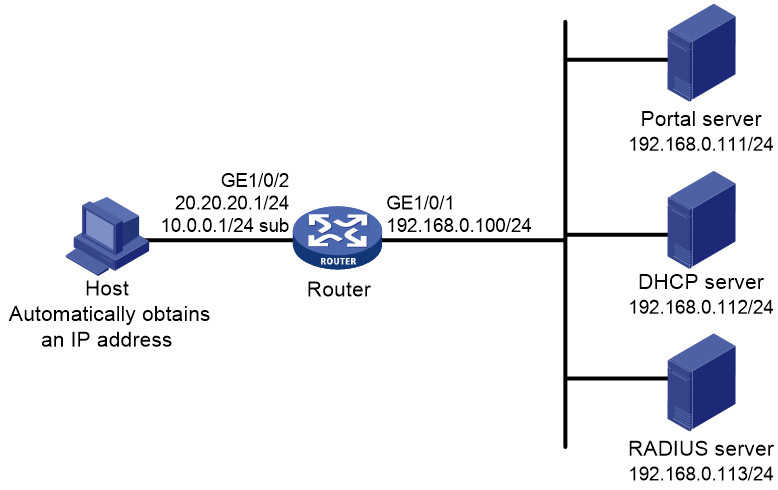
Restrictions and guidelines
· For re-DHCP portal authentication, configure a public address pool (20.20.20.0/24) and a private address pool (10.0.0.0/24) on the DHCP server. (Details not shown.)
· For re-DHCP portal authentication:
¡ The router must be configured as a DHCP relay agent.
¡ The portal-enabled interface must be configured with a primary IP address (a public IP address) and a secondary IP address (a private IP address).
For information about DHCP relay agent configuration, see Layer 3—IP Services Configuration Guide.
· Make sure the IP address of the portal device added on the portal server is the public IP address (20.20.20.1) of the router's interface connecting the host. The private IP address range for the IP address group associated with the portal device is the private subnet 10.0.0.0/24 where the host resides. The public IP address range for the IP address group is the public subnet 20.20.20.0/24.
Procedure
1. Configure the RADIUS server and the portal server correctly to provide authentication and accounting functions. (Details not shown.)
2. Assign IP addresses to interfaces and make sure the host, the router, and the servers can reach each other. (Details not shown.)
3. Configure a RADIUS scheme:
# Create a RADIUS scheme named rs1 and enter its view.
<Router> system-view
[Router] radius scheme rs1
# Specify the primary authentication server and primary accounting server, and configure the keys for communication with the servers.
[Router-radius-rs1] primary authentication 192.168.0.113
[Router-radius-rs1] primary accounting 192.168.0.113
[Router-radius-rs1] key authentication simple radius
[Router-radius-rs1] key accounting simple radius
# Exclude the ISP domain name from the username sent to the RADIUS server.
[Router-radius-rs1] user-name-format without-domain
[Router-radius-rs1] quit
# Enable RADIUS session control.
[Router] radius session-control enable
4. Configure an authentication domain:
# Create an ISP domain named dm1 and enter its view.
[Router] domain dm1
# Configure AAA methods for the ISP domain.
[Router-isp-dm1] authentication portal radius-scheme rs1
[Router-isp-dm1] authorization portal radius-scheme rs1
[Router-isp-dm1] accounting portal radius-scheme rs1
[Router-isp-dm1] quit
# Configure domain dm1 as the default ISP domain. If a user enters the username without the ISP domain name at login, the authentication and accounting methods of the default domain are used for the user.
[Router] domain default enable dm1
5. Configure DHCP relay and authorized ARP:
# Configure DHCP relay.
[Router] dhcp enable
[Router] dhcp relay client-information record
[Router] interface gigabitethernet 1/0/2
[Router–GigabitEthernet1/0/2] ip address 20.20.20.1 255.255.255.0
[Router–GigabitEthernet1/0/2] ip address 10.0.0.1 255.255.255.0 sub
[Router-GigabitEthernet1/0/2] dhcp select relay
[Router-GigabitEthernet1/0/2] dhcp relay server-address 192.168.0.112
# Enable authorized ARP.
[Router-GigabitEthernet1/0/2] arp authorized enable
[Router-GigabitEthernet1/0/2] quit
6. Configure portal authentication:
# Configure a portal authentication server.
[Router] portal server newpt
[Router-portal-server-newpt] ip 192.168.0.111 key simple portal
[Router-portal-server-newpt] port 50100
[Router-portal-server-newpt] quit
# Configure a portal Web server.
[Router] portal web-server newpt
[Router-portal-websvr-newpt] url http://192.168.0.111:8080/portal
[Router-portal-websvr-newpt] quit
# Enable re-DHCP portal authentication on GigabitEthernet 1/0/2.
[Router] interface gigabitethernet 1/0/2
[Router-GigabitEthernet1/0/2] portal enable method redhcp
# Specify portal Web server newpt on GigabitEthernet 1/0/2.
[Router–GigabitEthernet1/0/2] portal apply web-server newpt
# Configure the BAS-IP as 20.20.20.1 for portal packets sent from GigabitEthernet 1/0/2 to the portal authentication server.
[Router–GigabitEthernet1/0/2] portal bas-ip 20.20.20.1
[Router–GigabitEthernet1/0/2] quit
Verifying the configuration
# Verify that the portal configuration has taken effect.
[Router] display portal interface gigabitethernet 1/0/2
Portal information of GigabitEthernet1/0/2
NAS-ID profile: Not configured
Authorization : Strict checking
ACL : Disabled
User profile : Disabled
Dual stack : Disabled
Dual traffic-separate: Disabled
IPv4:
Portal status: Enabled
Portal authentication type: Redhcp
Portal Web server: newpt(active)
Secondary portal Web server: Not configured
Portal mac-trigger-server: Not configured
Authentication domain: Not configured
Pre-auth domain: Not configured
Extend-auth domain: Not configured
User-dhcp-only: Disabled
Pre-auth IP pool: Not configured
Max portal users: Not configured
Bas-ip: 20.20.20.1
User detection: Not configured
Portal temp-pass: Disabled
Action for server detection:
Server type Server name Action
-- -- --
Layer3 source network:
IP address Mask
Destination authenticate subnet:
IP address Mask
IPv6:
Portal status: Disabled
Portal authentication type: Disabled
Portal Web server: Not configured
Secondary portal Web server: Not configured
Portal mac-trigger-server: Not configured
Authentication domain: Not configured
Pre-auth domain: Not configured
Extend-auth domain: Not configured
User-dhcp-only: Disabled
Pre-auth IP pool: Not configured
Max portal users: Not configured
Bas-ipv6: Not configured
User detection: Not configured
Portal temp-pass: Disabled
Action for server detection:
Server type Server name Action
-- -- --
Layer3 source network:
IP address Prefix length
Destination authenticate subnet:
IP address Prefix length
Before passing the authentication, a user that uses the H3C iNode client can access only the authentication page http://192.168.0.111:8080/portal. All Web requests from the user will be redirected to the authentication page. After passing the authentication, the user can access other network resources.
# After the user passes authentication, display information about the portal user.
[Router] display portal user interface gigabitethernet 1/0/2
Total portal users: 1
Username: abc
Portal server: newpt
State: Online
VPN instance: N/A
MAC IP VLAN Interface
0015-e9a6-7cfe 20.20.20.2 -- GigabitEthernet1/0/2
Authorization information:
DHCP IP pool: N/A
User profile: N/A
Session group profile: N/A
ACL number/name: N/A
CAR: N/A
Inbound CAR: N/A
Outbound CAR: N/A
Example: Configuring cross-subnet portal authentication
Network configuration
As shown in Figure 13, Router A supports portal authentication. The host accesses Router A through Router B. A portal server acts as both a portal authentication server and a portal Web server. A RADIUS server acts as the authentication/accounting server.
Configure Router A for cross-subnet portal authentication. Before passing the authentication, the host can access only the portal server. After passing the authentication, the user can access other network resources.
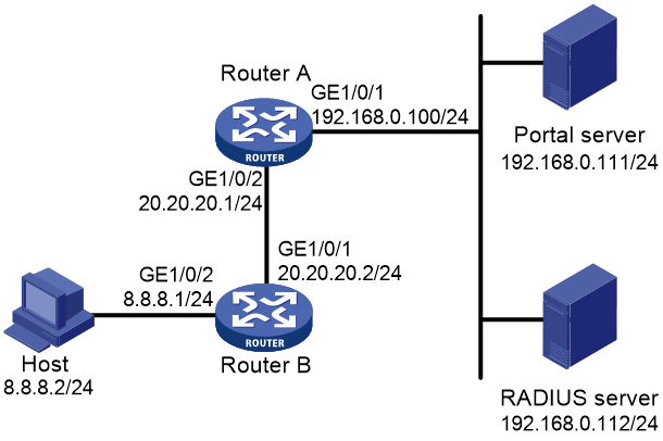
Restrictions and guidelines
Make sure the IP address of the portal device added on the portal authentication server is the IP address (20.20.20.1) of the router's interface connecting the host. The IP address group associated with the portal device is the subnet of the host (8.8.8.0/24).
Procedure
1. Configure the RADIUS server and the portal server correctly to provide authentication and accounting functions. (Details not shown.)
2. Assign IP addresses to interfaces and make sure the host, the routers, and the servers can reach each other. (Details not shown.)
3. Configure a RADIUS scheme:
# Create a RADIUS scheme named rs1 and enter its view.
<RouterA> system-view
[RouterA] radius scheme rs1
# Specify the primary authentication server and primary accounting server, and configure the keys for communication with the servers.
[RouterA-radius-rs1] primary authentication 192.168.0.112
[RouterA-radius-rs1] primary accounting 192.168.0.112
[RouterA-radius-rs1] key authentication simple radius
[RouterA-radius-rs1] key accounting simple radius
# Exclude the ISP domain name from the username sent to the RADIUS server.
[RouterA-radius-rs1] user-name-format without-domain
[RouterA-radius-rs1] quit
# Enable RADIUS session control.
[RouterA] radius session-control enable
4. Configure an authentication domain:
# Create an ISP domain named dm1 and enter its view.
[RouterA] domain dm1
# Configure AAA methods for the ISP domain.
[RouterA-isp-dm1] authentication portal radius-scheme rs1
[RouterA-isp-dm1] authorization portal radius-scheme rs1
[RouterA-isp-dm1] accounting portal radius-scheme rs1
[RouterA-isp-dm1] quit
# Configure domain dm1 as the default ISP domain. If a user enters the username without the ISP domain name at login, the authentication and accounting methods of the default domain are used for the user.
[RouterA] domain default enable dm1
5. Configure portal authentication:
# Configure a portal authentication server.
[RouterA] portal server newpt
[RouterA-portal-server-newpt] ip 192.168.0.111 key simple portal
[RouterA-portal-server-newpt] port 50100
[RouterA-portal-server-newpt] quit
# Configure a portal Web server.
[RouterA] portal web-server newpt
[RouterA-portal-websvr-newpt] url http://192.168.0.111:8080/portal
[RouterA-portal-websvr-newpt] quit
# Enable cross-subnet portal authentication on GigabitEthernet 1/0/2.
[RouterA] interface gigabitethernet 1/0/2
[RouterA–GigabitEthernet1/0/2] portal enable method layer3
# Specify portal Web server newpt on GigabitEthernet 1/0/2.
[RouterA–GigabitEthernet1/0/2] portal apply web-server newpt
# Configure the BAS-IP as 20.20.20.1 for portal packets sent from GigabitEthernet 1/0/2 to the portal authentication server.
[RouterA–GigabitEthernet1/0/2] portal bas-ip 20.20.20.1
[RouterA–GigabitEthernet1/0/2] quit
Verifying the configuration
# Verify that the portal configuration has taken effect.
[RouterA] display portal interface gigabitethernet 1/0/2
Portal information of GigabitEthernet1/0/2
NAS-ID profile: Not configured
Authorization : Strict checking
ACL : Disabled
User profile : Disabled
Dual stack : Disabled
Dual traffic-separate: Disabled
IPv4:
Portal status: Enabled
Portal authentication type: Layer3
Portal Web server: newpt(active)
Secondary portal Web server: Not configured
Portal mac-trigger-server: Not configured
Authentication domain: Not configured
Pre-auth domain: Not configured
Extend-auth domain: Not configured
User-dhcp-only: Disabled
Pre-auth IP pool: Not configured
Max portal users: Not configured
Bas-ip: 20.20.20.1
User detection: Not configured
Portal temp-pass: Disabled
Action for server detection:
Server type Server name Action
-- -- --
Layer3 source network:
IP address Mask
Destination authenticate subnet:
IP address Mask
IPv6:
Portal status: Disabled
Portal authentication type: Disabled
Portal Web server: Not configured
Secondary portal Web server: Not configured
Portal mac-trigger-server: Not configured
Authentication domain: Not configured
Pre-auth domain: Not configured
Extend-auth domain: Not configured
User-dhcp-only: Disabled
Pre-auth IP pool: Not configured
Max portal users: Not configured
Bas-ipv6: Not configured
User detection: Not configured
Portal temp-pass: Disabled
Action for server detection:
Server type Server name Action
-- -- --
Layer3 source network:
IP address Prefix length
Destination authenticate subnet:
IP address Prefix length
A user can perform portal authentication by using the H3C iNode client or through a Web browser. Before passing the authentication, the user can access only the authentication page http://192.168.0.111:8080/portal. All Web requests from the user will be redirected to the authentication page. After passing the authentication, the user can access other network resources.
# After the user passes authentication, display information about the portal user.
[RouterA] display portal user interface gigabitethernet 1/0/2
Total portal users: 1
Username: abc
Portal server: newpt
State: Online
VPN instance: N/A
MAC IP VLAN Interface
0015-e9a6-7cfe 8.8.8.2 -- GigabitEthernet1/0/2
Authorization information:
DHCP IP pool: N/A
User profile: N/A
Session group profile: N/A
ACL number/name: N/A
CAR: N/A
Inbound CAR: N/A
Outbound CAR: N/A
Example: Configuring extended direct portal authentication
Network configuration
As shown in Figure 14, the host is directly connected to the router (the access device). The host is assigned a public IP address either manually or through DHCP. A portal server acts as both a portal authentication server and a portal Web server. A RADIUS server acts as the authentication/accounting server.
Configure extended direct portal authentication. If the host fails security check after passing identity authentication, it can access only subnet 192.168.0.0/24. After passing security check, the host can access other network resources.

Procedure
1. Configure the RADIUS server and the portal server correctly to provide authentication and accounting functions. (Details not shown.)
2. Assign IP addresses to interfaces and make sure the host, the router, and the servers can reach each other. (Details not shown.)
3. Configure a RADIUS scheme:
# Create a RADIUS scheme named rs1 and enter its view.
<Router> system-view
[Router] radius scheme rs1
# Specify the primary authentication server and primary accounting server, and configure the keys for communication with the servers.
[Router-radius-rs1] primary authentication 192.168.0.112
[Router-radius-rs1] primary accounting 192.168.0.112
[Router-radius-rs1] key accounting simple radius
[Router-radius-rs1] key authentication simple radius
[Router-radius-rs1] user-name-format without-domain
# Enable RADIUS session control.
[Router] radius session-control enable
# Specify a session-control client with IP address 192.168.0.112 and shared key 12345 in plain text.
[Router] radius session-control client ip 192.168.0.112 key simple 12345
4. Configure an authentication domain:
# Create an ISP domain named dm1 and enter its view.
[Router] domain dm1
# Configure AAA methods for the ISP domain.
[Router-isp-dm1] authentication portal radius-scheme rs1
[Router-isp-dm1] authorization portal radius-scheme rs1
[Router-isp-dm1] accounting portal radius-scheme rs1
[Router-isp-dm1] quit
# Configure domain dm1 as the default ISP domain. If a user enters the username without the ISP domain name at login, the authentication and accounting methods of the default domain are used for the user.
[Router] domain default enable dm1
5. Configure ACL 3000 as the isolation ACL and ACL 3001 as the security ACL.
[Router] acl advanced 3000
[Router-acl-ipv4-adv-3000] rule permit ip destination 192.168.0.0 0.0.0.255
[Router-acl-ipv4-adv-3000] rule deny ip
[Router-acl-ipv4-adv-3000] quit
[Router] acl advanced 3001
[Router-acl-ipv4-adv-3001] rule permit ip
[Router-acl-ipv4-adv-3001] quit
|
|
NOTE: Make sure you specify ACL 3000 as the isolation ACL and ACL 3001 as the security ACL on the security policy server. |
6. Configure portal authentication:
# Configure a portal authentication server.
[Router] portal server newpt
[Router-portal-server-newpt] ip 192.168.0.111 key simple portal
[Router-portal-server-newpt] port 50100
[Router-portal-server-newpt] quit
# Configure a portal Web server.
[Router] portal web-server newpt
[Router-portal-websvr-newpt] url http://192.168.0.111:8080/portal
[Router-portal-websvr-newpt] quit
# Enable direct portal authentication on GigabitEthernet 1/0/2.
[Router] interface gigabitethernet 1/0/2
[Router–GigabitEthernet1/0/2] portal enable method direct
# Specify portal Web server newpt on GigabitEthernet 1/0/2.
[Router–GigabitEthernet1/0/2] portal apply web-server newpt
# Configure the BAS-IP as 2.2.2.1 for portal packets sent from GigabitEthernet 1/0/2 to the portal authentication server.
[Router–GigabitEthernet1/0/2] portal bas-ip 2.2.2.1
[Router–GigabitEthernet1/0/2] quit
Verifying the configuration
# Verify that the portal configuration has taken effect.
[Router] display portal interface gigabitethernet 1/0/2
Portal information of GigabitEthernet1/0/2
NAS-ID profile: Not configured
Authorization : Strict checking
ACL : Disabled
User profile : Disabled
Dual stack : Disabled
Dual traffic-separate: Disabled
IPv4:
Portal status: Enabled
Portal authentication type: Direct
Portal Web server: newpt(active)
Secondary portal Web server: Not configured
Portal mac-trigger-server: Not configured
Authentication domain: Not configured
Pre-auth domain: Not configured
Extend-auth domain: Not configured
User-dhcp-only: Disabled
Pre-auth IP pool: Not configured
Max portal users: Not configured
Bas-ip: 2.2.2.1
User detection: Not configured
Portal temp-pass: Disabled
Action for server detection:
Server type Server name Action
-- -- --
Layer3 source network:
IP address Mask
Destination authenticate subnet:
IP address Mask
IPv6:
Portal status: Disabled
Portal authentication type: Disabled
Portal Web server: Not configured
Secondary portal Web server: Not configured
Portal mac-trigger-server: Not configured
Authentication domain: Not configured
Pre-auth domain: Not configured
Extend-auth domain: Not configured
User-dhcp-only: Disabled
Pre-auth IP pool: Not configured
Max portal users: Not configured
Bas-ipv6: Not configured
User detection: Not configured
Portal temp-pass: Disabled
Action for server detection:
Server type Server name Action
-- -- --
Layer3 source network:
IP address Prefix length
Destination authenticate subnet:
IP address Prefix length
Before passing portal authentication, a user that uses the H3C iNode client can access only the authentication page http://192.168.0.111:8080/portal. All Web requests from the user will be redirected to the authentication page.
· The user can access the resources permitted by ACL 3000 after passing only identity authentication.
· The user can access network resources permitted by ACL 3001 after passing both identity authentication and security check.
# After the user passes identity authentication and security check, display information about the portal user.
[Router] display portal user interface gigabitethernet 1/0/2
Total portal users: 1
Username: abc
Portal server: newpt
State: Online
VPN instance: N/A
MAC IP VLAN Interface
0015-e9a6-7cfe 2.2.2.2 -- GigabitEthernet1/0/2
Authorization information:
DHCP IP pool: N/A
User profile: N/A
Session group profile: N/A
ACL number/name: 3001
CAR: N/A
Inbound CAR: N/A
Outbound CAR: N/A
Example: Configuring extended re-DHCP portal authentication
Network configuration
As shown in Figure 15, the host is directly connected to the router (the access device). The host obtains an IP address through the DHCP server. A portal server acts as both a portal authentication server and a portal Web server. A RADIUS server acts as the authentication/accounting server.
Configure extended re-DHCP portal authentication. Before passing portal authentication, the host is assigned a private IP address. After passing portal identity authentication, the host obtains a public IP address and accepts security check. If the host fails the security check, it can access only subnet 192.168.0.0/24. After passing the security check, the host can access other network resources.

Restrictions and guidelines
· For re-DHCP portal authentication, configure a public address pool (20.20.20.0/24) and a private address pool (10.0.0.0/24) on the DHCP server. (Details not shown.)
· For re-DHCP portal authentication:
¡ The router must be configured as a DHCP relay agent.
¡ The portal-enabled interface must be configured with a primary IP address (a public IP address) and a secondary IP address (a private IP address).
For information about DHCP relay agent configuration, see Layer 3—IP Services Configuration Guide.
· Make sure the IP address of the portal device added on the portal server is the public IP address (20.20.20.1) of the router's interface connecting the host. The private IP address range for the IP address group associated with the portal device is the private subnet 10.0.0.0/24 where the host resides. The public IP address range for the IP address group is the public subnet 20.20.20.0/24.
Procedure
1. Configure the RADIUS server and the portal server correctly to provide authentication and accounting functions. (Details not shown.)
2. Assign IP addresses to interfaces and make sure the host, the router, and the servers can reach each other. (Details not shown.)
3. Configure a RADIUS scheme:
# Create a RADIUS scheme named rs1 and enter its view.
<Router> system-view
[Router] radius scheme rs1
# Specify the primary authentication server and primary accounting server, and configure the keys for communication with the servers.
[Router-radius-rs1] primary authentication 192.168.0.113
[Router-radius-rs1] primary accounting 192.168.0.113
[Router-radius-rs1] key authentication simple radius
[Router-radius-rs1] key accounting simple radius
[Router-radius-rs1] user-name-format without-domain
# Enable RADIUS session control.
[Router] radius session-control enable
# Specify a session-control client with IP address 192.168.0.113 and shared key 12345 in plain text.
[Router] radius session-control client ip 192.168.0.113 key simple 12345
4. Configure an authentication domain:
# Create an ISP domain named dm1 and enter its view.
[Router] domain dm1
# Configure AAA methods for the ISP domain.
[Router-isp-dm1] authentication portal radius-scheme rs1
[Router-isp-dm1] authorization portal radius-scheme rs1
[Router-isp-dm1] accounting portal radius-scheme rs1
[Router-isp-dm1] quit
# Configure domain dm1 as the default ISP domain. If a user enters the username without the ISP domain name at login, the authentication and accounting methods of the default domain are used for the user.
[Router] domain default enable dm1
5. Configure ACL 3000 as the isolation ACL and ACL 3001 as the security ACL.
[Router] acl advanced 3000
[Router-acl-ipv4-adv-3000] rule permit ip destination 192.168.0.0 0.0.0.255
[Router-acl-ipv4-adv-3000] rule deny ip
[Router-acl-ipv4-adv-3000] quit
[Router] acl advanced 3001
[Router-acl-ipv4-adv-3001] rule permit ip
[Router-acl-ipv4-adv-3001] quit
|
|
NOTE: Make sure you specify ACL 3000 as the isolation ACL and ACL 3001 as the security ACL on the security policy server. |
6. Configure DHCP relay and authorized ARP:
# Configure DHCP relay.
[Router] dhcp enable
[Router] dhcp relay client-information record
[Router] interface gigabitethernet 1/0/2
[Router–GigabitEthernet1/0/2] ip address 20.20.20.1 255.255.255.0
[Router–GigabitEthernet1/0/2] ip address 10.0.0.1 255.255.255.0 sub
[Router-GigabitEthernet1/0/2] dhcp select relay
[Router-GigabitEthernet1/0/2] dhcp relay server-address 192.168.0.112
# Enable authorized ARP.
[Router-GigabitEthernet1/0/2] arp authorized enable
[Router-GigabitEthernet1/0/2] quit
7. Configure portal authentication:
# Configure a portal authentication server.
[Router] portal server newpt
[Router-portal-server-newpt] ip 192.168.0.111 key simple portal
[Router-portal-server-newpt] port 50100
[Router-portal-server-newpt] quit
# Configure a portal Web server.
[Router] portal web-server newpt
[Router-portal-websvr-newpt] url http://192.168.0.111:8080/portal
[Router-portal-websvr-newpt] quit
# Enable re-DHCP portal authentication on GigabitEthernet 1/0/2.
[Router] interface gigabitethernet 1/0/2
[Router-GigabitEthernet1/0/2] portal enable method redhcp
# Specify portal Web server newpt on GigabitEthernet 1/0/2.
[Router–GigabitEthernet1/0/2] portal apply web-server newpt
# Configure the BAS-IP as 20.20.20.1 for portal packets sent from GigabitEthernet 1/0/2 to the portal authentication server.
[Router–GigabitEthernet1/0/2] portal bas-ip 20.20.20.1
[Router–GigabitEthernet1/0/2] quit
Verifying the configuration
# Verify that the portal configuration has taken effect.
[Router] display portal interface gigabitethernet 1/0/2
Portal information of GigabitEthernet1/0/2
NAS-ID profile: Not configured
VSRP instance : Not configured
VSRP state : N/A
Authorization : Strict checking
ACL : Disabled
User profile : Disabled
Dual stack : Disabled
Dual traffic-separate: Disabled
IPv4:
Portal status: Enabled
Portal authentication type: Redhcp
Portal Web server: newpt(active)
Secondary portal Web server: Not configured
Portal mac-trigger-server: Not configured
Authentication domain: Not configured
Pre-auth domain: Not configured
Extend-auth domain: Not configured
User-dhcp-only: Disabled
Pre-auth IP pool: Not configured
Max portal users: Not configured
Bas-ip: 20.20.20.1
User detection: Not configured
Portal temp-pass: Disabled
Action for server detection:
Server type Server name Action
-- -- --
Layer3 source network:
IP address Mask
Destination authenticate subnet:
IP address Mask
IPv6:
Portal status: Disabled
Portal authentication type: Disabled
Portal Web server: Not configured
Secondary portal Web server: Not configured
Portal mac-trigger-server: Not configured
Authentication domain: Not configured
Pre-auth domain: Not configured
Extend-auth domain: Not configured
User-dhcp-only: Disabled
Pre-auth IP pool: Not configured
Max portal users: Not configured
Bas-ipv6: Not configured
User detection: Not configured
Portal temp-pass: Disabled
Action for server detection:
Server type Server name Action
-- -- --
Layer3 source network:
IP address Prefix length
Destination authenticate subnet:
IP address Prefix length
Before passing portal authentication, a user that uses the H3C iNode client can access only the authentication page http://192.168.0.111:8080/portal. All Web requests from the user will be redirected to the authentication page.
· The user can access the resources permitted by ACL 3000 after passing only identity authentication.
· The user can access network resources permitted by ACL 3001 after passing both identity authentication and security check.
# After the user passes identity authentication and security check, display information about the portal user.
[Router] display portal user interface gigabitethernet 1/0/2
Total portal users: 1
Username: abc
Portal server: newpt
State: Online
VPN instance: N/A
MAC IP VLAN Interface
0015-e9a6-7cfe 20.20.20.2 -- GigabitEthernet1/0/2
Authorization information:
DHCP IP pool: N/A
User profile: N/A
Session group profile: N/A
ACL number/name: 3001
CAR: N/A
Inbound CAR: N/A
Outbound CAR: N/A
Example: Configuring extended cross-subnet portal authentication
Network configuration
As shown in Figure 16, Router A supports portal authentication. The host accesses Router A through Router B. A portal server acts as both a portal authentication server and a portal Web server. A RADIUS server acts as the authentication/accounting server.
Configure Router A for extended cross-subnet portal authentication. Before passing portal authentication, the host can access only the portal server. After passing portal identity authentication, the host accepts security check. If the host fails the security check it can access only the subnet 192.168.0.0/24. After passing the security check, the host can access other network resources.
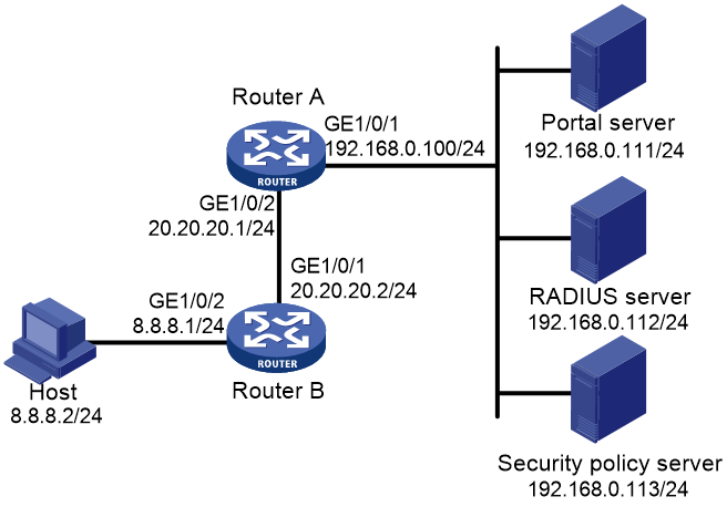
Restrictions and guidelines
Make sure the IP address of the portal device added on the portal server is the IP address (20.20.20.1) of the router's interface connecting the host. The IP address group associated with the portal device is the subnet of the host (8.8.8.0/24).
Procedure
1. Configure the RADIUS server and the portal server correctly to provide authentication and accounting functions. (Details not shown.)
2. Assign IP addresses to interfaces and make sure the host, the router, and the servers can reach each other. (Details not shown.)
3. Configure a RADIUS scheme:
# Create a RADIUS scheme named rs1 and enter its view.
<RouterA> system-view
[RouterA] radius scheme rs1
# Specify the primary authentication server and primary accounting server, and configure the keys for communication with the servers.
[RouterA-radius-rs1] primary authentication 192.168.0.112
[RouterA-radius-rs1] primary accounting 192.168.0.112
[RouterA-radius-rs1] key authentication simple radius
[RouterA-radius-rs1] key accounting simple radius
[RouterA-radius-rs1] user-name-format without-domain
# Enable RADIUS session control.
[RouterA] radius session-control enable
# Specify a session-control client with IP address 192.168.0.112 and shared key 12345 in plain text.
[RouterA] radius session-control client ip 192.168.0.112 key simple 12345
4. Configure an authentication domain:
# Create an ISP domain named dm1 and enter its view.
[RouterA] domain dm1
# Configure AAA methods for the ISP domain.
[RouterA-isp-dm1] authentication portal radius-scheme rs1
[RouterA-isp-dm1] authorization portal radius-scheme rs1
[RouterA-isp-dm1] accounting portal radius-scheme rs1
[RouterA-isp-dm1] quit
# Configure domain dm1 as the default ISP domain. If a user enters the username without the ISP domain name at login, the authentication and accounting methods of the default domain are used for the user.
[RouterA] domain default enable dm1
5. Configure ACL 3000 as the isolation ACL and ACL 3001 as the security ACL.
[RouterA] acl advanced 3000
[RouterA-acl-ipv4-adv-3000] rule permit ip destination 192.168.0.0 0.0.0.255
[RouterA-acl-ipv4-adv-3000] rule deny ip
[RouterA-acl-ipv4-adv-3000] quit
[RouterA] acl advanced 3001
[RouterA-acl-ipv4-adv-3001] rule permit ip
[RouterA-acl-ipv4-adv-3001] quit
|
|
NOTE: Make sure you specify ACL 3000 as the isolation ACL and ACL 3001 as the security ACL on the security policy server. |
6. Configure portal authentication:
# Configure a portal authentication server.
[RouterA] portal server newpt
[RouterA-portal-server-newpt] ip 192.168.0.111 key simple portal
[RouterA-portal-server-newpt] port 50100
[RouterA-portal-server-newpt] quit
# Configure a portal Web server.
[Router] portal web-server newpt
[RouterA-portal-websvr-newpt] url http://192.168.0.111:8080/portal
[RouterA-portal-websvr-newpt] quit
# Enable cross-subnet portal authentication on GigabitEthernet 1/0/2.
[RouterA] interface gigabitethernet 1/0/2
[RouterA–GigabitEthernet1/0/2] portal enable method layer3
# Specify portal Web server newpt on GigabitEthernet 1/0/2.
[RouterA–GigabitEthernet1/0/2] portal apply web-server newpt
# Configure the BAS-IP as 20.20.20.1 for portal packets sent from GigabitEthernet 1/0/2 to the portal authentication server.
[RouterA–GigabitEthernet1/0/2] portal bas-ip 20.20.20.1
[RouterA–GigabitEthernet1/0/2] quit
Verifying the configuration
# Verify that the portal configuration has taken effect.
[RouterA] display portal interface gigabitethernet 1/0/2
Portal information of GigabitEthernet1/0/2
NAS-ID profile: Not configured
Authorization : Strict checking
ACL : Disabled
User profile : Disabled
Dual stack : Disabled
Dual traffic-separate: Disabled
IPv4:
Portal status: Enabled
Portal authentication type: Layer3
Portal Web server: newpt(active)
Secondary portal Web server: Not configured
Portal mac-trigger-server: Not configured
Authentication domain: Not configured
Pre-auth domain: Not configured
Extend-auth domain: Not configured
User-dhcp-only: Disabled
Pre-auth IP pool: Not configured
Max portal users: Not configured
Bas-ip: 20.20.20.1
User detection: Not configured
Portal temp-pass: Disabled
Action for server detection:
Server type Server name Action
-- -- --
Layer3 source network:
IP address Mask
Destination authenticate subnet:
IP address Mask
IPv6:
Portal status: Disabled
Authentication type: Disabled
Portal Web server: Not configured
Secondary portal Web server: Not configured
Portal mac-trigger-server: Not configured
Authentication domain: Not configured
Pre-auth domain: Not configured
Extend-auth domain: Not configured
User-dhcp-only: Disabled
Pre-auth IP pool: Not configured
Max portal users: Not configured
Bas-ipv6: Not configured
User detection: Not configured
Portal temp-pass: Disabled
Action for server detection:
Server type Server name Action
-- -- --
Layer3 source network:
IP address Prefix length
Destination authenticate subnet:
IP address Prefix length
Before passing portal authentication, a user that uses the H3C iNode client can access only the authentication page http://192.168.0.111:8080/portal. All Web requests from the user are redirected to the authentication page.
· The user can access the resources permitted by ACL 3000 after passing only identity authentication.
· The user can access network resources permitted by ACL 3001 after passing both identity authentication and security check.
# After the user passes identity authentication and security check, display information about the portal user.
[RouterA] display portal user interface gigabitethernet 1/0/2
Total portal users: 1
Username: abc
Portal server: newpt
State: Online
VPN instance: N/A
MAC IP VLAN Interface
0015-e9a6-7cfe 8.8.8.2 -- GigabitEthernet1/0/2
Authorization information:
DHCP IP pool: N/A
User profile: N/A
Session group profile: N/A
ACL number/name: 3001
CAR: N/A
Inbound CAR: N/A
Outbound CAR: N/A
Example: Configuring portal server detection and portal user synchronization
Network configuration
As shown in Figure 17, the host is directly connected to the router (the access device). The host is assigned a public IP address either manually or through DHCP. A portal server acts as both a portal authentication server and a portal Web server. A RADIUS server acts as the authentication/accounting server.
Configure direct portal authentication on the router, so the host can access only the portal server before passing the authentication and access other network resources after passing the authentication.
Configure the router to do the following:
· Detect the reachability state of the portal authentication server.
· Send log messages upon state changes.
· Disable portal authentication when the authentication server is unreachable.
· Synchronize portal user information with the portal server periodically.
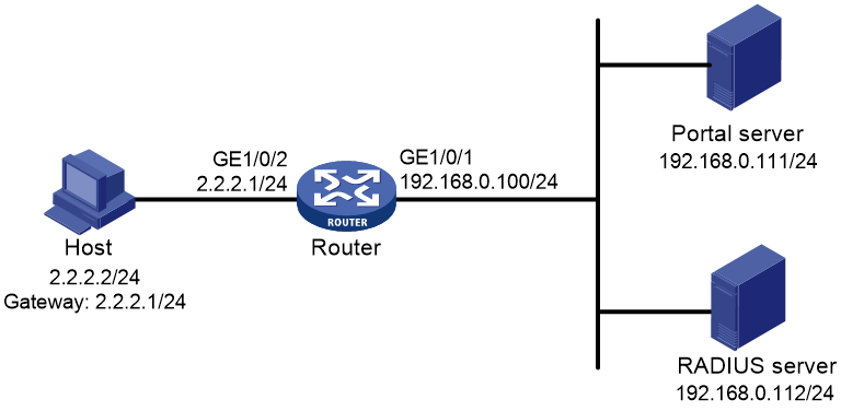
Configuring the RADIUS server
# Configure the RADIUS server correctly to provide authentication and accounting functions. (Details not shown.)
Configuring the portal authentication server on IMC PLAT 5.0
In this example, the portal server runs on IMC PLAT 5.0(E0101) and IMC UAM 5.0(E0101).
1. Configure the portal authentication server:
a. Log in to IMC and click the Service tab.
b. Select User Access Manager > Portal Service Management > Server from the navigation tree to open the portal server configuration page, as shown in Figure 18.
c. Configure the portal server heartbeat interval and user heartbeat interval.
d. Use the default settings for other parameters.
e. Click OK.
Figure 18 Portal authentication server configuration

2. Configure the IP address group:
a. Select User Access Manager > Portal Service Management > IP Group from the navigation tree to open the portal IP address group configuration page.
b. Click Add to open the page as shown in Figure 19.
c. Enter the IP group name.
d. Enter the start IP address and end IP address of the IP group.
Make sure the host IP address is in the IP group.
e. Select a service group.
This example uses the default group Ungrouped.
f. Select Normal from the Action list.
g. Click OK.
Figure 19 Adding an IP address group

3. Add a portal device:
a. Select User Access Manager > Portal Service Management > Device from the navigation tree to open the portal device configuration page.
b. Click Add to open the page as shown in Figure 20.
c. Enter the device name NAS.
d. Enter the IP address of the router's interface connected to the host.
e. Enter the key, which must be the same as that configured on the router.
f. Set whether to enable IP address reallocation.
This example uses direct portal authentication, and therefore select No from the Reallocate IP list.
g. Select whether to support server heartbeat and user heartbeat functions.
In this example, select Yes for both Support Server Heartbeat and Support User Heartbeat.
h. Click OK.
Figure 20 Adding a portal device

4. Associate the portal device with the IP address group:
a. As shown in Figure 21, click the icon in the Port Group Information Management column of device NAS to open the port group configuration page.
b. Click Add to open the page as shown in Figure 22.
c. Enter the port group name.
d. Select the configured IP address group.
The IP address used by the user to access the network must be within this IP address group.
e. Use the default settings for other parameters.
f. Click OK.


5. Select User Access Manager > Service Parameters > Validate System Configuration from the navigation tree to make the configurations take effect.
Configuring the router
1. Assign IP addresses to interfaces and make sure the host, the router, and the servers can reach each other. (Details not shown.)
2. Configure a RADIUS scheme:
# Create a RADIUS scheme named rs1 and enter its view.
<Router> system-view
[Router] radius scheme rs1
# Specify the primary authentication server and primary accounting server, and configure the keys for communication with the servers.
[Router-radius-rs1] primary authentication 192.168.0.112
[Router-radius-rs1] primary accounting 192.168.0.112
[Router-radius-rs1] key authentication simple radius
[Router-radius-rs1] key accounting simple radius
# Exclude the ISP domain name from the username sent to the RADIUS server.
[Router-radius-rs1] user-name-format without-domain
[Router-radius-rs1] quit
# Enable RADIUS session control.
[Router] radius session-control enable
3. Configure an authentication domain:
# Create an ISP domain named dm1 and enter its view.
[Router] domain dm1
# Configure AAA methods for the ISP domain.
[Router-isp-dm1] authentication portal radius-scheme rs1
[Router-isp-dm1] authorization portal radius-scheme rs1
[Router-isp-dm1] accounting portal radius-scheme rs1
[Router-isp-dm1] quit
# Configure domain dm1 as the default ISP domain. If a user enters the username without the ISP domain name at login, the authentication and accounting methods of the default domain are used for the user.
[Router] domain default enable dm1
4. Configure portal authentication:
# Configure a portal authentication server.
[Router] portal server newpt
[Router-portal-server-newpt] ip 192.168.0.111 key simple portal
[Router-portal-server-newpt] port 50100
# Configure reachability detection of the portal authentication server: set the server detection interval to 40 seconds, and send log messages upon reachability status changes.
[Router-portal-server-newpt] server-detect timeout 40 log
|
|
NOTE: The value of timeout must be greater than or equal to the portal server heartbeat interval. |
# Configure portal user synchronization with the portal authentication server, and set the synchronization detection interval to 600 seconds.
[Router-portal-server-newpt] user-sync timeout 600
[Router-portal-server-newpt] quit
|
|
NOTE: The value of timeout must be greater than or equal to the portal user heartbeat interval. |
# Configure a portal Web server.
[Router] portal web-server newpt
[Router-portal-websvr-newpt] url http://192.168.0.111:8080/portal
[Router-portal-websvr-newpt] quit
# Enable direct portal authentication on GigabitEthernet 1/0/2.
[Router] interface gigabitethernet 1/0/2
[Router–GigabitEthernet1/0/2] portal enable method direct
# Enable portal fail-permit for the portal authentication server newpt.
[Router–GigabitEthernet1/0/2] portal fail-permit server newpt
# Specify portal Web server newpt on GigabitEthernet 1/0/2.
[Router–GigabitEthernet1/0/2] portal apply web-server newpt
# Configure the BAS-IP as 2.2.2.1 for portal packets sent from GigabitEthernet 1/0/2 to the portal authentication server.
[Router–GigabitEthernet1/0/2] portal bas-ip 2.2.2.1
[Router–GigabitEthernet1/0/2] quit
Verifying the configuration
# Display information about the portal authentication server.
[Router] display portal server newpt
Portal server: newpt
Type : IMC
IP : 192.168.0.111
VPN instance : Not configured
Port : 50100
Server Detection : Timeout 40s Action: log
User synchronization : Timeout 600s
Status : Up
Exclude-attribute : Not configured
Logout notification : Not configured
The Up status of the portal authentication server indicates that the portal authentication server is reachable. If the access device detects that the portal authentication server is unreachable, the Status field in the command output displays Down. The access device generates a server unreachable log "Portal server newpt turns down from up." and disables portal authentication on the access interface, so the host can access the external network without authentication.
Example: Configuring cross-subnet portal authentication for MPLS L3VPNs
Network configuration
As shown in Figure 23, the PE device Router A provides portal authentication for the host in VPN 1. A portal server in VPN 3 acts as the portal authentication server, portal Web server, and RADIUS server.
Configure cross-subnet portal authentication on Router A, so the host can access network resources after passing identity authentication.
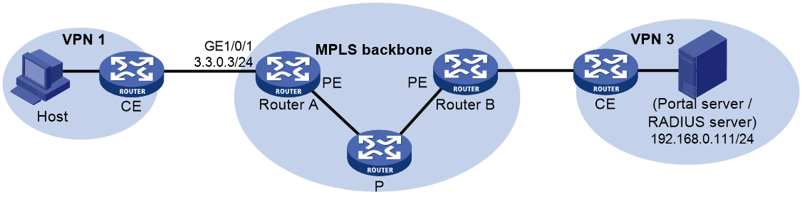
Prerequisites
Before enabling portal authentication, configure MPLS L3VPN and specify VPN targets for VPN 1 and VPN 3 so that VPN 1 and VPN 3 can communicate with each other. This example describes only the access authentication configuration on the user-side PE. For information about VPN configurations, see MPLS L3VPN configuration in MPLS Configuration Guide.
Procedure
1. Configure the RADIUS server and the portal server correctly to provide authentication and accounting functions. (Details not shown.)
2. Assign IP addresses to interfaces and make sure the host, the router, and the servers can reach each other. (Details not shown.)
3. Configure a RADIUS scheme:
# Create a RADIUS scheme named rs1 and enter its view.
<RouterA> system-view
[RouterA] radius scheme rs1
# For the RADIUS scheme, specify the VPN instance that is bound to the interface connected to the portal/RADIUS server. This example uses VPN instance vpn3. (For information about the VPN instance, see the MPLS L3VPN configuration on Router A.)
[RouterA-radius-rs1] vpn-instance vpn3
# Specify the primary authentication server and primary accounting server, and configure the keys for communication with the servers.
[RouterA-radius-rs1] primary authentication 192.168.0.111
[RouterA-radius-rs1] primary accounting 192.168.0.111
[RouterA-radius-rs1] key accounting simple radius
[RouterA-radius-rs1] key authentication simple radius
# Exclude the ISP domain name from the username sent to the RADIUS server.
[RouterA-radius-rs1] user-name-format without-domain
# Specify the source IP address for RADIUS packets to be sent as 3.3.0.3. This address must be the same as that of the portal device specified on the portal authentication server to avoid authentication failures.
[RouterA-radius-rs1] nas-ip 3.3.0.3
[RouterA-radius-rs1] quit
# Enable RADIUS session control.
[RouterA] radius session-control enable
4. Configure an authentication domain:
# Create an ISP domain named dm1 and enter its view.
[RouterA] domain dm1
# Configure AAA methods for the ISP domain.
[RouterA-isp-dm1] authentication portal radius-scheme rs1
[RouterA-isp-dm1] authorization portal radius-scheme rs1
[RouterA-isp-dm1] accounting portal radius-scheme rs1
[RouterA-isp-dm1] quit
# Configure domain dm1 as the default ISP domain. If a user enters the username without the ISP domain name at login, the authentication and accounting methods of the default domain are used for the user.
[RouterA] domain default enable dm1
5. Configure portal authentication:
# Configure a portal authentication server.
[RouterA] portal server newpt
[RouterA-portal-server-newpt] ip 192.168.0.111 vpn-instance vpn3 key simple portal
[RouterA-portal-server-newpt] port 50100
[RouterA-portal-server-newpt] quit
# Configure a portal Web server.
[RouterA] portal web-server newpt
[RouterA-portal-websvr-newpt] url http://192.168.0.111:8080/portal
[RouterA-portal-websvr-newpt] vpn-instance vpn3
[RouterA-portal-websvr-newpt] quit
# Enable cross-subnet portal authentication on GigabitEthernet 1/0/1.
[RouterA] interface gigabitethernet 1/0/1
[RouterA–GigabitEthernet1/0/1] portal enable method layer3
# Specify portal Web server newpt on GigabitEthernet 1/0/1.
[RouterA–GigabitEthernet1/0/1] portal apply web-server newpt
# Configure the BAS-IP as 3.3.0.3 for portal packets sent from GigabitEthernet 1/0/1 to the portal authentication server.
[RouterA–GigabitEthernet1/0/1] portal bas-ip 3.3.0.3
[RouterA–GigabitEthernet1/0/1] quit
Verifying the configuration
# Verify the portal configuration by executing the display portal interface command. (Details not shown.)
# After the user passes authentication, display the portal user information.
[RouterA] display portal user all
Total portal users: 1
Username: abc
Portal server: newpt
State: Online
VPN instance: vpn3
MAC IP VLAN Interface
0000-0000-0000 3.3.0.1 -- GigabitEthernet1/0/1
Authorization information:
DHCP IP pool: N/A
User profile: N/A
Session group profile: N/A
ACL number/name: N/A
CAR: N/A
Inbound CAR: N/A
Outbound CAR: N/A
Example: Configuring direct portal authentication with a preauthentication domain
Network configuration
As shown in Figure 24, the host is directly connected to the router (the access device). The host is assigned a public IP address through DHCP. A portal server acts as both a portal authentication server and a portal Web server. A RADIUS server acts as the authentication/accounting server.
Configure direct portal authentication, so the host can access only subnet 192.168.0.0/24 before passing the authentication and access other network resources after passing the authentication.
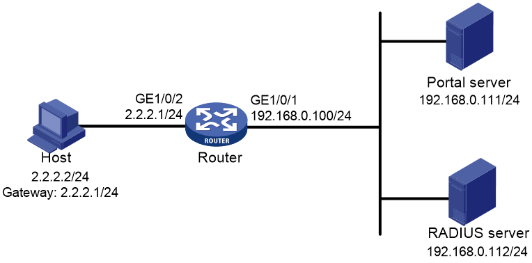
Procedure
1. Configure the RADIUS server and the portal server correctly to provide authentication and accounting functions. (Details not shown.)
2. Assign IP addresses to interfaces and make sure the host, the router, and the servers can reach each other. (Details not shown.)
3. Configure a preauthentication IP address pool:
# Configure DHCP address pool pre to assign IP addresses and other configuration parameters to clients on subnet 2.2.2.0/24.
<Router> system-view
[Router] dhcp server ip-pool pre
[Router-dhcp-pool-pre] gateway-list 2.2.2.1
[Router-dhcp-pool-pre] network 2.2.2.0 24
[Router-dhcp-pool-pre] quit
# Enable the DHCP server on GigabitEthernet 1/0/2.
[Router] interface gigabitethernet 1/0/2
[Router–GigabitEthernet1/0/2] dhcp select server
[Router–GigabitEthernet1/0/2] quit
4. Configure a portal preauthentication domain:
# Create an ISP domain named abc.
[Router] domain abc
# Specify user attribute ACL 3010 in the ISP domain.
[Router-isp-abc] authorization-attribute acl 3010
[Router-isp-abc] quit
# In ACL 3010, configure a rule to permit access to the subnet 192.168.0.0/24.
[Router] acl advanced 3010
[Router-acl-ipv4-adv-3010] rule 1 permit ip destination 192.168.0.0 0.0.0.255
[Router-acl-ipv4-adv-3010] quit
# Specify ISP domain abc as the portal preauthentication domain on GigabitEthernet 1/0/2.
[Router] interface gigabitethernet 1/0/2
[Router–GigabitEthernet1/0/2] portal pre-auth domain abc
[Router–GigabitEthernet1/0/2] quit
5. Configure portal authentication:
# Configure a portal authentication server.
[Router] portal server newpt
[Router-portal-server-newpt] ip 192.168.0.111 key simple portal
[Router-portal-server-newpt] port 50100
[Router-portal-server-newpt] quit
# Configure a portal Web server.
[Router] portal web-server newpt
[Router-portal-websvr-newpt] url http://192.168.0.111:8080/portal
[Router-portal-websvr-newpt] quit
# Enable direct portal authentication on GigabitEthernet 1/0/2.
[Router] interface gigabitethernet 1/0/2
[Router–GigabitEthernet1/0/2] portal enable method direct
# Specify portal Web server newpt on GigabitEthernet 1/0/2.
[Router–GigabitEthernet1/0/2] portal apply web-server newpt
# Configure the BAS-IP as 2.2.2.1 for portal packets sent from GigabitEthernet 1/0/2 to the portal authentication server.
[Router–GigabitEthernet1/0/2] portal bas-ip 2.2.2.1
[Router–GigabitEthernet1/0/2] quit
Verifying the configuration
# Verify the portal configuration by executing the display portal interface command. (Details not shown.)
# Display information about preauthentication portal users.
[Router] display portal user pre-auth interface gigabitethernet 1/0/2
Total portal pre-auth users: 1
MAC IP VLAN Interface
0015-e9a6-7cfe 2.2.2.4 -- GigabitEthernet1/0/2
State: Online
VPN instance: --
Authorization information:
DHCP IP pool: N/A
User profile: N/A
Session group profile: N/A
ACL number/name: 3010
Inbound CAR: N/A
Outbound CAR: N/A
Example: Configuring re-DHCP portal authentication with a preauthentication domain
Network configuration
As shown in Figure 25, the host is directly connected to the router (the access device). The host obtains an IP address through the DHCP server. A portal server acts as both a portal authentication server and a portal Web server. A RADIUS server acts as the authentication/accounting server.
Configure re-DHCP portal authentication. Before passing the authentication, the host is assigned a private IP address and can access only the subnet 192.168.0.0/24. After passing the authentication, the host gets a public IP address and can access other network resources.

Restrictions and guidelines
· For re-DHCP portal authentication, configure a public address pool (20.20.20.0/24) and a private address pool (10.0.0.0/24) on the DHCP server. (Details not shown.)
· For re-DHCP portal authentication:
¡ The router must be configured as a DHCP relay agent.
¡ The portal-enabled interface must be configured with a primary IP address (a public IP address) and a secondary IP address (a private IP address).
For information about DHCP relay agent configuration, see Layer 3—IP Services Configuration Guide.
· Make sure the IP address of the portal device added on the portal server is the public IP address (20.20.20.1) of the router's interface connecting the host. The private IP address range for the IP address group associated with the portal device is the private subnet 10.0.0.0/24 where the host resides. The public IP address range for the IP address group is the public subnet 20.20.20.0/24.
· If you have configured a preauthentication IP address pool on portal-enabled interfaces, configure a DHCP relay address pool with the same name on the device. For the DHCP relay address pool, specify the subnet address where the unauthenticated users reside (with the export-router keyword specified) and the DHCP server address.
Procedure
1. Configure the RADIUS server and the portal server correctly to provide authentication and accounting functions. (Details not shown.)
2. Assign IP addresses to interfaces and make sure the host, the router, and the servers can reach each other. (Details not shown.)
3. Configure a portal preauthentication domain:
# Create an ISP domain named abc.
<Router> system-view
[Router] domain abc
# Specify user attribute ACL 3010 in the domain.
[Router-isp-abc] authorization-attribute acl 3010
[Router-isp-abc] quit
# In ACL 3010, configure a rule to permit access to the subnet 192.168.0.0/24.
[Router] acl advanced 3010
[Router-acl-ipv4-adv-3010] rule 1 permit ip destination 192.168.0.0 0.0.0.255
[Router-acl-ipv4-adv-3010] quit
# Specify ISP domain abc as the portal preauthentication domain on GigabitEthernet 1/0/2.
[Router] interface gigabitethernet 1/0/2
[Router–GigabitEthernet1/0/2] portal pre-auth domain abc
[Router–GigabitEthernet1/0/2] quit
4. Configure DHCP relay and authorized ARP.
# Configure DHCP relay.
[Router] dhcp enable
[Router] dhcp relay client-information record
[Router] interface gigabitethernet 1/0/2
[Router–GigabitEthernet1/0/2] ip address 20.20.20.1 255.255.255.0
[Router–GigabitEthernet1/0/2] ip address 10.0.0.1 255.255.255.0 sub
[Router-GigabitEthernet1/0/2] dhcp select relay
[Router-GigabitEthernet1/0/2] dhcp relay server-address 192.168.0.112
# Enable authorized ARP.
[Router-GigabitEthernet1/0/2] arp authorized enable
[Router-GigabitEthernet1/0/2] quit
5. Configure portal authentication:
# Configure a portal authentication server.
[Router] portal server newpt
[Router-portal-server-newpt] ip 192.168.0.111 key simple portal
[Router-portal-server-newpt] port 50100
[Router-portal-server-newpt] quit
# Configure a portal Web server.
[Router] portal web-server newpt
[Router-portal-websvr-newpt] url http://192.168.0.111:8080/portal
[Router-portal-websvr-newpt] quit
# Enable re-DHCP portal authentication on GigabitEthernet 1/0/2.
[Router] interface gigabitethernet 1/0/2
[Router–GigabitEthernet1/0/2] portal enable method redhcp
# Specify portal Web server newpt on GigabitEthernet 1/0/2.
[Router–GigabitEthernet1/0/2] portal apply web-server newpt
# Configure the BAS-IP as 20.20.20.1 for portal packets sent from GigabitEthernet 1/0/2 to the portal authentication server.
[Router–GigabitEthernet1/0/2] portal bas-ip 20.20.20.1
[Router–GigabitEthernet1/0/2] quit
Verifying the configuration
# Verify the portal configuration by executing the display portal interface command. (Details not shown.)
# Display information about preauthentication portal users.
[Router] display portal user pre-auth interface gigabitethernet 1/0/2
Total portal pre-auth users: 1
MAC IP VLAN Interface
0015-e9a6-7cfe 10.10.10.4 -- GigabitEthernet1/0/2
State: Online
VPN instance: --
DHCP IP pool: N/A
User profile: N/A
Session group profile: N/A
ACL number/name: 3010
Inbound CAR: N/A
Outbound CAR: N/A
Example: Configuring direct portal authentication using a local portal Web service
Network configuration
As shown in Figure 26, the host is directly connected to the router (the access device). The host is assigned a public IP address either manually or through DHCP. The router acts as both a portal authentication server and a portal Web server. A RADIUS server acts as the authentication/accounting server.
Configure direct portal authentication on the router. Before a user passes portal authentication, the user can access only the portal Web server. After passing portal authentication, the user can access other network resources.

Prerequisites
Customize the authentication pages, compress them to a file, and upload the file to the root directory of the storage medium of the router.
Procedure
1. Configure the RADIUS server and the portal server correctly to provide authentication and accounting functions. (Details not shown.)
2. Assign IP addresses to interfaces and make sure the host, the router, and the servers can reach each other. (Details not shown.)
3. Configure a RADIUS scheme:
# Create a RADIUS scheme named rs1 and enter its view.
<Router> system-view
[Router] radius scheme rs1
# Specify the primary authentication server and primary accounting server, and configure the keys for communication with the servers.
[Router-radius-rs1] primary authentication 192.168.0.112
[Router-radius-rs1] primary accounting 192.168.0.112
[Router-radius-rs1] key authentication simple radius
[Router-radius-rs1] key accounting simple radius
# Exclude the ISP domain name from the username sent to the RADIUS server.
[Router-radius-rs1] user-name-format without-domain
[Router-radius-rs1] quit
# Enable RADIUS session control.
[Router] radius session-control enable
4. Configure an authentication domain:
# Create an ISP domain named dm1 and enter its view.
[Router] domain dm1
# Configure AAA methods for the ISP domain.
[Router-isp-dm1] authentication portal radius-scheme rs1
[Router-isp-dm1] authorization portal radius-scheme rs1
[Router-isp-dm1] accounting portal radius-scheme rs1
[Router-isp-dm1] quit
# Configure domain dm1 as the default ISP domain. If a user enters the username without the ISP domain name at login, the authentication and accounting methods of the default domain are used for the user.
[Router] domain default enable dm1
5. Configure portal authentication:
# Create a portal Web server named newpt and specify http://2.2.2.1:2331/portal as the URL of the portal Web server. The IP address in the URL must be the IP address of a Layer 3 interface routable to the portal client or a loopback interface (except 127.0.0.1) on the device.
[Router] portal web-server newpt
[Router-portal-websvr-newpt] url http://2.2.2.1:2331/portal
[Router-portal-websvr-newpt] quit
# Enable direct portal authentication on GigabitEthernet 1/0/2.
[Router] interface gigabitethernet 1/0/2
[Router–GigabitEthernet1/0/2] portal enable method direct
# Specify portal Web server newpt on GigabitEthernet 1/0/2.
[Router–GigabitEthernet1/0/2] portal apply web-server newpt
[Router–GigabitEthernet1/0/2] quit
# Create an HTTP-based local portal Web service and enter its view.
[Router] portal local-web-server http
# Specify file abc.zip as the default authentication page file for the local portal Web service. (Make sure the file exist under the root directory of the router.)
[Router–portal-local-websvr-http] default-logon-page abc.zip
# Set the HTTP listening port number to 2331 for the local portal Web service.
[Router–portal-local-websvr-http] tcp-port 2331
[Router–portal-local-websvr-http] quit
Verifying the configuration
# Verify that the portal configuration has taken effect.
[Router] display portal interface gigabitethernet 1/0/2
Portal information of GigabitEthernet1/0/2
Authorization :Strict checking
ACL :Disabled
User profile :Disabled
Dual stack : Disabled
Dual traffic-separate: Disabled
IPv4:
Portal status: Enabled
Portal authentication type: Direct
Portal Web server: newpt(active)
Secondary portal Web server: Not configured
Portal mac-trigger-server: Not configured
Authentication domain: Not configured
Pre-auth domain: Not configured
Extend-auth domain: Not configured
User-dhcp-only: Disabled
Pre-auth IP pool: Not configured
Max portal users: Not configured
Bas-ip: Not configured
User detection: Not configured
Portal temp-pass: Disabled
Action for server detection:
Server type Server name Action
-- -- --
Layer3 source network:
IP address Mask
Destination authenticate subnet:
IP address Mask
IPv6:
Portal status: Disabled
Portal authentication type: Disabled
Portal Web server: Not configured
Secondary portal Web server: Not configured
Portal mac-trigger-server: Not configured
Authentication domain: Not configured
Pre-auth domain: Not configured
Extend-auth domain: Not configured
User-dhcp-only: Disabled
Pre-auth IP pool: Not configured
Max portal users: Not configured
Bas-ipv6: Not configured
User detection: Not configured
Portal temp-pass: Disabled
Action for server detection:
Server type Server name Action
-- -- --
Layer3 source network:
IP address Prefix length
Destination authenticate subnet:
IP address Prefix length
A user can perform portal authentication through a Web page. Before passing the authentication, the user can access only the authentication page http://2.2.2.1:2331/portal and all Web requests will be redirected to the authentication page. After passing the authentication, the user can access other network resources.
# After the user passes authentication, use the following command to display information about the portal user.
[Router] display portal user interface gigabitethernet 1/0/2
Total portal users: 1
Username: abc
Portal server: newpt
State: Online
VPN instance: --
MAC IP VLAN Interface
0015-e9a6-7cfe 2.2.2.2 -- GigabitEthernet1/0/2
Authorization information:
DHCP IP pool: N/A
User profile: N/A
Session group profile: N/A
ACL number/name: N/A
CAR: N/A
Inbound CAR: N/A
Outbound CAR: N/A
Example: Configuring MAC-based quick portal authentication
Network configuration
As shown in Figure 27, the host accesses the network through the router. The host is assigned a public IP address either manually or through DHCP. A portal server acts as a portal authentication server, a portal Web server, and a MAC binding server. A RADIUS server acts as the authentication/accounting server.
Configure direct portal authentication, so the host can access only the portal Web server before passing the authentication and can access other network resources after passing the authentication.
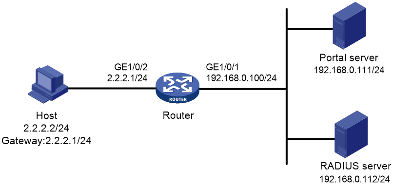
Configuring the RADIUS server
# Configure the RADIUS server correctly to provide authentication and accounting functions. (Details not shown.)
Configuring the portal server
In this example, the portal server runs on IMC PLAT 7.1(E0303), IMC EIA 7.1(F0303), and IMC EIP 7.1(F0303).
1. Configure the portal authentication server:
a. Log in to IMC and click the User tab.
b. Select User Access Policy > Portal Service > Server from the navigation tree to open the portal server configuration page, as shown in Figure 28.
c. Configure the portal server parameters as needed.
This example uses the default values.
d. Click OK.
Figure 28 Portal authentication server configuration

2. Configure the IP address group:
a. Select User Access Policy > Portal Service > IP Group from the navigation tree to open the portal IP address group configuration page.
b. Click Add to open the page as shown in Figure 29.
c. Enter the IP group name.
d. Enter the start IP address and end IP address of the IP group.
Make sure the client IP address (2.2.2.2) is in the IP group.
e. Select a service group.
This example uses the default group Ungrouped.
f. Select Normal from the Action list.
g. Click OK.
Figure 29 Adding an IP address group

3. Add a portal device:
a. Select User Access Policy > Portal Service > Device from the navigation tree to open the portal device configuration page.
b. Click Add to open the page as shown in Figure 30.
c. Enter the device name.
d. Enter the IP address of the router's interface connected to the host.
e. Set whether to support the portal server heartbeat and user heartbeat functions.
In this example, select No for both Support Server Heartbeat and Support User Heartbeat.
f. Enter the key, which must be the same as that configured on the router.
g. Select Directly Connected for Access Method.
h. Click OK.
Figure 30 Adding a portal device
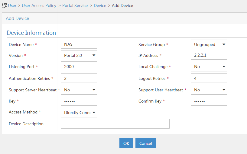
4. Associate the portal device with the IP address group:
a. As shown in Figure 31, click the Port Group Information Management icon for device NAS to open the port group configuration page.
b. Click Add to open the page as shown in Figure 32.
c. Enter the port group name.
d. Select the configured IP address group.
The IP address used by the user to access the network must be within this IP address group.
e. Select Supported for Transparent Authentication.
f. Use the default settings for other parameters.
g. Click OK.


5. Select User Access Policy > Service Parameters > Validate System Configuration from the navigation tree to make the configurations take effect.
Configuring the MAC binding server
In this example, the MAC binding server runs on IMC PLAT 7.1(E0303), IMC EIA 7.1(F0303), and IMC EIP 7.1(F0303).
1. Add an access policy:
a. Select User Access Policy > Access Policy from the navigation tree to open the access policy page.
b. Click Add to open the page as shown in Figure 33.
c. Enter the access policy name.
d. Select a service group.
e. Use the default settings for other parameters.
f. Click OK.
Figure 33 Adding an access policy
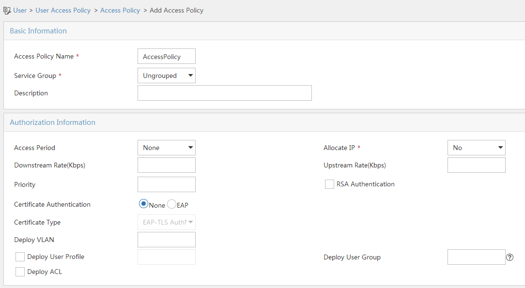
2. Add an access service:
a. Select User Access Policy > Access Service from the navigation tree to open the access service page.
b. Click Add to open the page as shown in Figure 34.
c. Enter the service name.
d. Select the Transparent Authentication on Portal Endpoints option.
e. Use the default settings for other parameters.
f. Click OK.
Figure 34 Adding an access service

3. Add an access user:
a. Select Access User > All Access Users from the navigation tree to open the access user page.
b. Click Add to open the page as shown in Figure 35.
c. Select an access user.
d. Set the password.
e. Select a value from the Max. Transparent Portal Bindings list.
f. Click OK.
Figure 35 Adding an access user
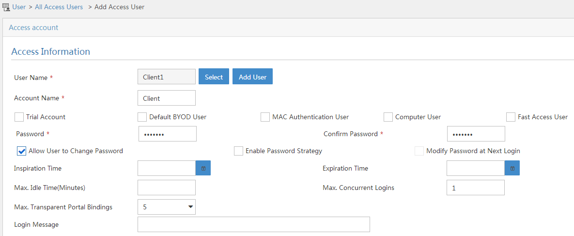
4. Configure system parameters:
a. Select User Access Policy > Service Parameters > System Settings from the navigation tree to open the system settings page.
b. Click the Configure
icon ![]() for User Endpoint Settings to open the page as shown in Figure 36.
for User Endpoint Settings to open the page as shown in Figure 36.
c. Select whether to enable transparent portal authentication on non-smart devices.
In this example, select Enable for Non-Terminal Authentication.
d. Click OK.
e. Click the Configure
icon ![]() for Endpoint Aging Time to open the page as shown in Figure 37.
for Endpoint Aging Time to open the page as shown in Figure 37.
f. Set the endpoint aging time as needed.
This example uses the default value.
Figure 36 Configuring user endpoint settings
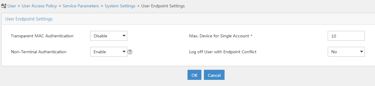
Figure 37 Setting the endpoint aging time
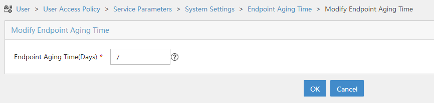
5. Select User Access Policy > Service Parameters > Validate System Configuration from the navigation tree to make the configurations take effect.
Configuring the router
1. Assign IP addresses to interfaces and make sure the host, the router, and the servers can reach each other. (Details not shown.)
2. Configure a RADIUS scheme:
# Create a RADIUS scheme named rs1 and enter its view.
<Router> system-view
[Router] radius scheme rs1
# Specify the primary authentication server and primary accounting server, and configure the keys for communication with the servers.
[Router-radius-rs1] primary authentication 192.168.0.112
[Router-radius-rs1] primary accounting 192.168.0.112
[Router-radius-rs1] key authentication simple radius
[Router-radius-rs1] key accounting simple radius
# Exclude the ISP domain name from the username sent to the RADIUS server.
[Router-radius-rs1] user-name-format without-domain
[Router-radius-rs1] quit
# Enable RADIUS session control.
[Router] radius session-control enable
3. Configure an authentication domain:
# Create an ISP domain named dm1 and enter its view.
[Router] domain dm1
# Configure AAA methods for the ISP domain.
[Router-isp-dm1] authentication portal radius-scheme rs1
[Router-isp-dm1] authorization portal radius-scheme rs1
[Router-isp-dm1] accounting portal radius-scheme rs1
[Router-isp-dm1] quit
# Configure domain dm1 as the default ISP domain. If a user enters the username without the ISP domain name at login, the authentication and accounting methods of the default domain are used for the user.
[Router] domain default enable dm1
4. Configure portal authentication:
# Configure a portal authentication server.
[Router] portal server newpt
[Router-portal-server-newpt] ip 192.168.0.111 key simple portal
[Router-portal-server-newpt] port 50100
[Router-portal-server-newpt] quit
# Configure a portal Web server.
[Router] portal web-server newpt
[Router-portal-websvr-newpt] url http://192.168.0.111:8080/portal
[Router-portal-websvr-newpt] quit
# Enable direct authentication on GigabitEthernet 1/0/2.
[Router] interface gigabitethernet 1/0/2
[Router-GigabitEthernet1/0/2] portal enable method direct
# Specify the portal Web server newpt on GigabitEthernet 1/0/2.
[Router-GigabitEthernet1/0/2] portal apply web-server newpt
# Configure the BAS-IP as 2.2.2.1 for portal packets sent from GigabitEthernet 1/0/2 to the portal authentication server.
[Router-GigabitEthernet1/0/2] portal bas-ip 2.2.2.1
[Router-GigabitEthernet1/0/2] quit
5. Configure MAC-based quick portal authentication:
# Create the MAC binding server mts.
[Router] portal mac-trigger-server mts
# Set the free-traffic threshold for portal users to 1024000 bytes.
[Router-portal-mac-trigger-server-mts] free-traffic threshold 1024000
# Specify the IP address of the MAC binding server as 192.168.0.111.
[Router-portal-mac-trigger-server-mts] ip 192.168.0.111
[Router-portal-mac-trigger-server-mts] quit
# Specify the MAC binding server mts on GigabitEthernet 1/0/2.
[Router] interface gigabitethernet 1/0/2
[Router-GigabitEthernet1/0/2] portal apply mac-trigger-server mts
[Router-GigabitEthernet1/0/2] quit
Verifying the configuration
# Display information about the MAC binding server.
[Router] display portal mac-trigger-server name mts
Portal mac trigger server name: mts
Version : 1.0
Server type : IMC
IP : 192.168.0.111
Port : 50100
VPN instance : Not configured
Aging time : 300 seconds
Free-traffic threshold : 1024000 bytes
NAS-Port-Type : Not configured
Binding retry times : 3
Binding retry interval : 1 seconds
Authentication timeout : 3 minutes
Local-binding : Disabled
Local-binding aging-time : 12 hours
aaa-fail nobinding : Disabled
Excluded attribute list : Not configured
Cloud-binding : Disabled
Cloud-server URL : Not configured
A user can perform portal authentication by using the H3C iNode client or through a Web browser. Before passing the authentication, the user can access only the authentication page http://192.168.0.111:8080/portal. All Web requests from the user will be redirected to the authentication page. After passing the authentication, the user can access other network resources.
For the first portal authentication, the user is required to enter the username and password. When the user goes offline and then accesses the network again, the user does not need to enter the authentication username and password.
# Display portal user information.
[Router] display portal user interface gigabitethernet 1/0/2
Total portal users: 1
Username: Client1
Portal server: newpt
State: Online
VPN instance: N/A
MAC IP VLAN Interface
0015-e9a6-7cfe 2.2.2.2 -- GigabitEthernet1/0/2
Authorization information:
DHCP IP pool: N/A
User profile: N/A
Session group profile: N/A
ACL number/name: N/A
CAR: N/A
Inbound CAR: N/A
Outbound CAR: N/A
Portal configuration examples (on ACs)
Example: Configuring direct portal authentication on a VLAN interface
Network configuration
As shown in Figure 38, the AP directly forwards user traffic from the client. The client is assigned a public IP address either manually or through DHCP. A portal server acts as both a portal authentication server and a portal Web server. A RADIUS server acts as the authentication/accounting server.
Configure direct portal authentication, so the client can access only the portal Web server before passing the authentication and access other network resources after passing the authentication.

Configuring the RADIUS server
# Configure the RADIUS server correctly to provide authentication and accounting functions. (Details not shown.)
Configuring the portal server
In this example, the portal server runs on IMC PLAT 5.0(E0101) and IMC UAM 5.0(E0101).
1. Configure the portal authentication server:
a. Log in to IMC and click the Service tab.
b. Select User Access Manager > Portal Service Management > Server from the navigation tree to open the portal server configuration page, as shown in Figure 39.
c. Configure the portal server parameters as needed.
This example uses the default settings.
d. Click OK.
Figure 39 Portal server configuration

2. Configure the IP address group:
a. Select User Access Manager > Portal Service Management > IP Group from the navigation tree to open the portal IP address group configuration page.
b. Click Add to open the page as shown in Figure 40.
Figure 40 Adding an IP address group

a. Enter the IP group name.
b. Enter the start IP address and end IP address of the IP group.
Make sure the host IP address is in the IP group.
c. Select a service group.
This example uses the default group Ungrouped.
d. Select the action Normal.
e. Click OK.
3. Add a portal device:
a. Select User Access Manager > Portal Service Management > Device from the navigation tree to open the portal device configuration page.
b. Click Add to open the page as shown in Figure 41.
c. Enter the device name NAS.
d. Enter the IP address of the AC's interface that exchanges information with the portal server.
e. Enter the key, which must be the same as that configured on the AC.
f. Set whether to enable IP address reallocation.
This example uses direct portal authentication, and therefore select No from the Reallocate IP list.
g. Select whether to support sever heartbeat and user heartbeat functions.
In this example, select No for both Support Server Heartbeat and Support User Heartbeat.
h. Click OK.
Figure 41 Adding a portal device
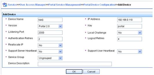
4. Associate the portal device with the IP address group:
a. As shown in Figure 42, click the icon in the Port Group Information Management column of device NAS to open the port group configuration page.
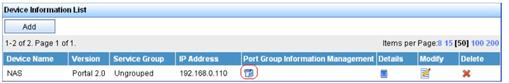
a. Click Add to open the page as shown in Figure 43.

a. Enter the port group name.
b. Select the configured IP address group.
The IP address used by the user to access the network must be within this IP address group.
c. Use the default settings for other parameters.
d. Click OK.
5. Select User Access Manager > Service Parameters > Validate System Configuration from the navigation tree to make the configurations take effect.
Configuring the AC
1. Assign IP addresses to interfaces and make sure the client, the AC, and the servers can reach each other. (Details not shown.)
2. Configure a RADIUS scheme:
# Create a RADIUS scheme named rs1 and enter its view.
<AC> system-view
[AC] radius scheme rs1
# Specify the primary authentication server and primary accounting server, and configure the keys for communication with the servers.
[AC-radius-rs1] primary authentication 192.168.0.112
[AC-radius-rs1] primary accounting 192.168.0.112
[AC-radius-rs1] key authentication simple radius
[AC-radius-rs1] key accounting simple radius
# Exclude the ISP domain name from the username sent to the RADIUS server.
[AC-radius-rs1] user-name-format without-domain
[AC-radius-rs1] quit
# Enable RADIUS session control.
[AC] radius session-control enable
3. Configure an authentication domain:
# Create an ISP domain named dm1 and enter its view.
[AC] domain dm1
# Configure AAA methods for the ISP domain.
[AC-isp-dm1] authentication portal radius-scheme rs1
[AC-isp-dm1] authorization portal radius-scheme rs1
[AC-isp-dm1] accounting portal radius-scheme rs1
[AC-isp-dm1] quit
# Configure domain dm1 as the default ISP domain. If a user enters the username without the ISP domain name at login, the authentication and accounting methods of the default domain are used for the user.
[AC] domain default enable dm1
4. Configure portal authentication:
# Configure a portal authentication server.
[AC] portal server newpt
[AC-portal-server-newpt] ip 192.168.0.111 key simple portal
[AC-portal-server-newpt] port 50100
[AC-portal-server-newpt] quit
# Configure a portal Web server.
[AC] portal web-server newpt
[AC-portal-websvr-newpt] url http://192.168.0.111:8080/portal
[AC-portal-websvr-newpt] quit
# Enable direct portal authentication on VLAN-interface 100.
[AC] interface vlan-interface 100
[AC–Vlan-interface100] portal enable method direct
# Specify portal Web server newpt on VLAN-interface 100.
[AC–Vlan-interface100] portal apply web-server newpt
# Configure the BAS-IP as 2.2.2.1 for portal packets sent from the AC to the portal authentication server.
[AC–Vlan-interface100] portal bas-ip 2.2.2.1
[AC–Vlan-interface100] quit
Verifying the configuration
# Verify that the portal configuration has taken effect.
[AC] display portal interface vlan-interface 100
Portal information of Vlan-interface100
NAS-ID profile: Not configured
VSRP instance : Not configured
VSRP state : N/A
Authorization : Strict checking
ACL : Disabled
User profile : Disabled
Dual stack : Disabled
Dual traffic-separate: Disabled
IPv4:
Portal status: Enabled
VSRP_SM state: M_Delay
Portal authentication method: Direct
Portal Web server: newpt(active)
Secondary portal Web server: Not configured
Portal mac-trigger-server: Not configured
Authentication domain: Not configured
Pre-auth domain: Not configured
User-dhcp-only: Disabled
Pre-auth IP pool: Not configured
Max portal users: Not configured
Bas-ip: 2.2.2.1
User Detection: Not configured
Action for server detection:
Server type Server name Action
-- -- --
Layer3 source network:
IP address Mask
Destination authenticate subnet:
IP address Mask
IPv6:
Portal status: Disabled
VSRP_SM state: M_Delay
Portal authentication method: Disabled
Portal Web server: Not configured
Secondary portal Web server: Not configured
Portal mac-trigger-server: Not configured
Authentication domain: Not configured
Pre-auth domain: Not configured
User-dhcp-only: Disabled
Pre-auth IP pool: Not configured
Max portal users: Not configured
Bas-ipv6: Not configured
User detection: Not configured
Action for server detection:
Server type Server name Action
-- -- --
Layer3 source network:
IP address Prefix length
Destination authenticate subnet:
IP address Prefix length
A user can perform portal authentication by using the H3C iNode client or a Web browser. Before passing the authentication, the user can access only the authentication page http://192.168.0.111:8080/portal. All Web requests from the user will be redirected to the authentication page. After passing the authentication, the user can access other network resources.
# After the user passes authentication, display information about the portal user.
[AC] display portal user interface vlan-interface 100
Total portal users: 1
Username: abc
Portal server: newpt
State: Online
VPN instance: N/A
MAC IP VLAN Interface
0015-e9a6-7cfe 2.2.2.2 100 Vlan-interface100
Authorization information:
DHCP IP pool: N/A
User profile: N/A
Session group profile: N/A
ACL: N/A
Example: Configuring direct portal authentication on a service template
Network configuration
As shown in Figure 44, the AP directly forwards user traffic from the client. The client is assigned a public IP address either manually or through DHCP. A portal server acts as both a portal authentication server and a portal Web server. A RADIUS server acts as the authentication/accounting server.
Configure direct portal authentication, so the client can access only the portal Web server before passing the authentication and access other network resources after passing the authentication.
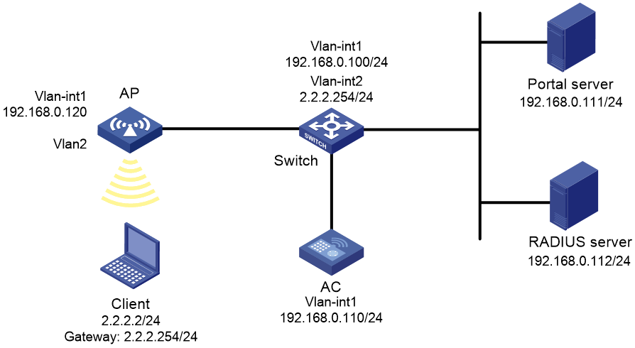
Configuring the RADIUS server
# Configure the RADIUS server correctly to provide authentication and accounting functions. (Details not shown.)
Configuring the portal server
For more information about configuring the portal server, see "Example: Configuring direct portal authentication on a VLAN interface."
Configuring the AP
# Configure the AP to make sure the AP can communicate with the AC. (Details not shown.)
Configuring the AC
1. Assign IP addresses to interfaces and make sure the client, the AC, and the servers can reach each other. (Details not shown.)
2. Configure a RADIUS scheme:
# Create a RADIUS scheme named rs1 and enter its view.
<AC> system-view
[AC] radius scheme rs1
# Specify the primary authentication server and primary accounting server, and configure the keys for communication with the servers.
[AC-radius-rs1] primary authentication 192.168.0.112
[AC-radius-rs1] primary accounting 192.168.0.112
[AC-radius-rs1] key authentication simple radius
[AC-radius-rs1] key accounting simple radius
# Exclude the ISP domain name from the username sent to the RADIUS server.
[AC-radius-rs1] user-name-format without-domain
[AC-radius-rs1] quit
# Enable RADIUS session control.
[AC] radius session-control enable
3. Configure an authentication domain:
# Create an ISP domain named dm1 and enter its view.
[AC] domain dm1
# Configure AAA methods for the ISP domain.
[AC-isp-dm1] authentication portal radius-scheme rs1
[AC-isp-dm1] authorization portal radius-scheme rs1
[AC-isp-dm1] accounting portal radius-scheme rs1
[AC-isp-dm1] quit
# Configure domain dm1 as the default ISP domain. If a user enters the username without the ISP domain name at login, the authentication and accounting methods of the default domain are used for the user.
[AC] domain default enable dm1
4. Configure portal authentication:
# Configure a portal authentication server.
[AC] portal server newpt
[AC-portal-server-newpt] ip 192.168.0.111 key simple portal
[AC-portal-server-newpt] port 50100
[AC-portal-server-newpt] quit
# Configure a portal Web server.
[AC] portal web-server newpt
[AC-portal-websvr-newpt] url http://192.168.0.111:8080/portal
[AC-portal-websvr-newpt] quit
# Create the manual AP ap2, and specify the AP model and serial ID.
[AC] wlan ap ap2 model WA4320i-ACN
[AC-wlan-ap-ap2] serial-id 210235A29G007C000020
# Create service template newst, set the SSID to portal 1.
[AC] wlan service-template newst
[AC–wlan-st-newst] ssid portal_1
# Enable direct authentication on service template newst.
[AC–wlan-st-newst] portal enable method direct
# Specify the portal Web server newpt on service template newst.
[AC–wlan-st-newst] portal apply web-server newpt
# Configure the BAS-IP as 192.168.0.110 for portal packets sent from the AC to the portal authentication server.
[AC–wlan-st-newst] portal bas-ip 192.168.0.110
# Configure the AP to forward client data traffic.
[AC–wlan-st-newst] client forwarding-location ap
# Enable service template newst.
[AC–wlan-st-newst] service-template enable
[AC–wlan-st-newst] quit
# Set the working channel to channel 11 for radio 2 of the AP.
[AC] wlan ap ap2
[AC-wlan-ap-ap2] radio 2
[AC-wlan-ap-ap2-radio-2] channel 11
# Enable radio 2 and bind service template newst and VLAN 2 to radio 2.
[AC-wlan-ap-ap2-radio-2] radio enable
[AC-wlan-ap-ap2-radio-2] service-template newst vlan 2
[AC-wlan-ap-ap2-radio-2] quit
[AC-wlan-ap-ap2] quit
Verifying the configuration
# Verify that the portal configuration has taken effect.
[AC] display portal ap ap2
Portal information of ap2
Radio ID: 2
SSID: portal_1
Authorization : Strict checking
ACL : Disable
User profile : Disable
Dual stack : Disabled
Dual traffic-separate: Disabled
IPv4:
Portal status: Enabled
VSRP_SM state: M_Delay
Portal authentication method: Direct
Portal Web server: newpt(active)
Secondary portal Web server: Not configured
Portal mac-trigger-server: Not configured
Authentication domain: Not configured
User-dhcp-only: Disabled
Max portal users: Not configured
Bas-ip: 192.168.0.110
Action for server detection:
Server type Server name Action
-- -- --
Destination authentication subnet:
IP address Mask
IPv6:
Portal status: Disabled
VSRP_SM state: M_Delay
Portal authentication method: Disabled
Portal Web server: Not configured
Secondary portal Web server: Not configured
Portal mac-trigger-server: Not configured
Authentication domain: Not configured
User-dhcp-only: Disabled
Max portal users: Not configured
Bas-ipv6: Not configured
Action for server detection:
Server type Server name Action
-- -- --
Destination authentication subnet:
IP address Prefix length
A user can perform portal authentication by using the H3C iNode client or a Web browser. Before passing the authentication, the user can access only the authentication page http://192.168.0.111:8080/portal. All Web requests from the user will be redirected to the authentication page. After passing the authentication, the user can access other network resources.
# After the user passes authentication, display information about the portal user.
[AC] display portal user ap ap2
Total portal users: 1
Username: 1
AP name: ap2
Radio ID: 2
SSID: portal_1
Portal server: newpt
State: Online
VPN instance: N/A
MAC IP VLAN Interface
0015-005e-9398 2.2.2.2 2 WLAN-BSS1/0/1
Authorization information:
DHCP IP pool: N/A
User profile: N/A
Session group profile: N/A
ACL number: N/A
Example: Configuring extended direct portal authentication
Network configuration
As shown in Figure 45, the client is connected to the AC through the AP. The client is assigned a public IP address either manually or through DHCP. A portal server acts as both a portal authentication server and a portal Web server. A RADIUS server acts as the authentication/accounting server.
Configure extended direct portal authentication. If the client fails security check after passing identity authentication, it can access only subnet 192.168.0.0/24. After passing security check, the client can access other network resources.
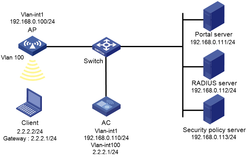
Configuring the RADIUS server and the portal server
# Configure the RADIUS server and the portal server correctly to provide authentication and accounting functions. (Details not shown.)
Configuring the AC
1. Assign IP addresses to interfaces and make sure the client, the AC, and the servers can reach each other. (Details not shown.)
2. Configure a RADIUS scheme:
# Create a RADIUS scheme named rs1 and enter its view.
<AC> system-view
[AC] radius scheme rs1
# Specify the primary authentication server and primary accounting server, and configure the keys for communication with the servers.
[AC-radius-rs1] primary authentication 192.168.0.112
[AC-radius-rs1] primary accounting 192.168.0.112
[AC-radius-rs1] key accounting simple radius
[AC-radius-rs1] key authentication simple radius
# Exclude the ISP domain name from the username sent to the RADIUS server.
[AC-radius-rs1] user-name-format without-domain
# Specify a security policy server with IP address 192.168.0.113.
[AC-radius-rs1] security-policy-server 192.168.0.113
[AC-radius-rs1] quit
# Enable RADIUS session control.
[AC] radius session-control enable
# Specify a session-control client with IP address 192.168.0.112 and shared key 12345 in plaintext form.
[AC] radius session-control client ip 192.168.0.112 key simple 12345
3. Configure an authentication domain:
# Create an ISP domain named dm1 and enter its view.
[AC] domain dm1
# Configure AAA methods for the ISP domain.
[AC-isp-dm1] authentication portal radius-scheme rs1
[AC-isp-dm1] authorization portal radius-scheme rs1
[AC-isp-dm1] accounting portal radius-scheme rs1
[AC-isp-dm1] quit
# Configure domain dm1 as the default ISP domain. If a user enters the username without the ISP domain name at login, the authentication and accounting methods of the default domain are used for the user.
[AC] domain default enable dm1
4. Configure ACL 3000 as the isolation ACL and ACL 3001 as the security ACL.
[AC] acl advanced 3000
[AC-acl-ipv4-adv-3000] rule permit ip destination 192.168.0.0 0.0.0.255
[AC-acl-ipv4-adv-3000] rule deny ip
[AC-acl-ipv4-adv-3000] quit
[AC] acl advanced 3001
[AC-acl-ipv4-adv-3001] rule permit ip
[AC-acl-ipv4-adv-3001] quit
|
|
NOTE: Make sure you specify ACL 3000 as the isolation ACL and ACL 3001 as the security ACL on the security policy server. |
5. Configure portal authentication:
# Configure a portal authentication server.
[AC] portal server newpt
[AC-portal-server-newpt] ip 192.168.0.111 key simple portal
[AC-portal-server-newpt] port 50100
[AC-portal-server-newpt] quit
# Configure a portal Web server.
[AC] portal web-server newpt
[AC-portal-websvr-newpt] url http://192.168.0.111:8080/portal
[AC-portal-websvr-newpt] quit
# Enable direct portal authentication on VLAN-interface 100.
[AC] interface vlan-interface 100
[AC–Vlan-interface100] portal enable method direct
# Specify portal Web server newpt on VLAN-interface 100.
[AC–Vlan-interface100] portal apply web-server newpt
# Configure the BAS-IP as 2.2.2.1 for portal packets sent from VLAN-interface 100 to the portal authentication server.
[AC–Vlan-interface100] portal bas-ip 2.2.2.1
[AC–Vlan-interface100] quit
Verifying the configuration
# Verify that the portal configuration has taken effect.
[AC] display portal interface vlan-interface 100
Portal information of Vlan-interface100
NAS-ID profile: Not configured
VSRP instance : Not configured
VSRP state : N/A
Authorization : Strict checking
ACL : Disabled
User profile : Disabled
Dual stack : Disabled
Dual traffic-separate: Disabled
IPv4:
Portal status: Enabled
Portal authentication method: Direct
Portal Web server: newpt(active)
Secondary portal Web server: Not configured
Portal mac-trigger-server: Not configured
Authentication domain: Not configured
Pre-auth domain: Not configured
User-dhcp-only: Disabled
Pre-auth IP pool: Not configured
Max portal users: Not configured
Bas-ip: 2.2.2.1
User Detection: Not configured
Action for server detection:
Server type Server name Action
-- -- --
Layer3 source network:
IP address Mask
Destination authenticate subnet:
IP address Mask
IPv6:
Portal status: Disabled
Portal authentication method: Disabled
Portal Web server: Not configured
Secondary portal Web server: Not configured
Portal mac-trigger-server: Not configured
Authentication domain: Not configured
Pre-auth domain: Not configured
User-dhcp-only: Disabled
Pre-auth IP pool: Not configured
Max portal users: Not configured
Bas-ipv6: Not configured
User detection: Not configured
Action for server detection:
Server type Server name Action
-- -- --
Layer3 source network:
IP address Prefix length
Destination authenticate subnet:
IP address Prefix length
Before passing portal authentication, a user that uses the H3C iNode client can access only the authentication page http://192.168.0.111:8080/portal. All Web requests from the user will be redirected to the authentication page.
· The user can access the resources permitted by ACL 3000 after passing only identity authentication.
· The user can access network resources permitted by ACL 3001 after passing both identity authentication and security check.
# After the user passes identity authentication and security check, display information about the portal user.
[AC] display portal user interface vlan-interface 100
Total portal users: 1
Username: abc
Portal server: newpt
State: Online
VPN instance: N/A
MAC IP VLAN Interface
0015-e9a6-7cfe 2.2.2.2 -- Vlan-interface100
Authorization information:
DHCP IP pool: N/A
User profile: N/A
Session group profile: N/A
ACL: 3001
Example: Configuring portal server detection
Network configuration
As shown in Figure 46, the client is connected to the AC through the AP. The client is assigned a public IP address either manually or through DHCP. A portal server acts as both a portal authentication server and a portal Web server. A RADIUS server acts as the authentication/accounting server.
· Configure direct portal authentication on the AC, so the client can access only the portal server before passing the authentication and access other network resources after passing the authentication.
· Configure the AC to detect the reachability state of the portal authentication server, send log messages upon state changes, and disable portal authentication when the authentication server is unreachable.
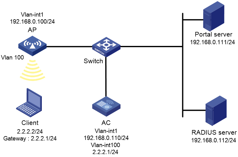
Configuring the RADIUS server
# Configure the RADIUS server correctly to provide authentication and accounting functions. (Details not shown.)
Configuring the portal authentication server
In this example, the portal server runs on IMC PLAT 5.0(E0101) and IMC UAM 5.0(E0101).
1. Configure the portal authentication server:
a. Log in to IMC and click the Service tab.
b. Select User Access Manager > Portal Service Management > Server from the navigation tree to open the portal server configuration page, as shown in Figure 47.
c. Configure the portal server heartbeat interval and user heartbeat interval.
d. Use the default settings for other parameters.
e. Click OK.
Figure 47 Portal authentication server configuration

2. Configure the IP address group:
a. Select User Access Manager > Portal Service Management > IP Group from the navigation tree to open the portal IP address group configuration page.
b. Click Add to open the page as shown in Figure 48.
c. Enter the IP group name.
d. Enter the start IP address and end IP address of the IP group.
Make sure the host IP address is in the IP group.
e. Select a service group.
This example uses the default group Ungrouped.
f. Select the action Normal.
g. Click OK.
Figure 48 Adding an IP address group

3. Add a portal device:
a. Select User Access Manager > Portal Service Management > Device from the navigation tree to open the portal device configuration page.
b. Click Add to open the page as shown in Figure 49.
c. Enter the device name NAS.
d. Enter the IP address of the AC's interface connected to the host.
e. Enter the key, which must be the same as that configured on the AC.
f. Set whether to enable IP address reallocation.
This example uses direct portal authentication, and therefore select No from the Reallocate IP list.
g. Select whether to support server heartbeat and user heartbeat functions.
In this example, select Yes for both Support Server Heartbeat and Support User Heartbeat.
h. Click OK.
Figure 49 Adding a portal device

4. Associate the portal device with the IP address group:
a. As shown in Figure 50, click the icon in the Port Group Information Management column of device NAS to open the port group configuration page.
b. Click Add to open the page as shown in Figure 51.
c. Enter the port group name.
d. Select the configured IP address group.
The IP address used by the user to access the network must be within this IP address group.
e. Use the default settings for other parameters.
f. Click OK.

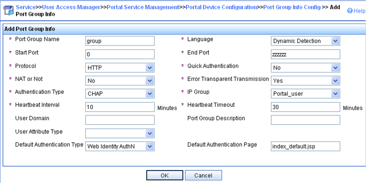
5. Select User Access Manager > Service Parameters > Validate System Configuration from the navigation tree to make the configurations take effect.
Configuring the AC
1. Assign IP addresses to interfaces and make sure the client, the AC, and the servers can reach each other. (Details not shown.)
2. Configure a RADIUS scheme:
# Create a RADIUS scheme named rs1 and enter its view.
<AC> system-view
[AC] radius scheme rs1
# Specify the primary authentication server and primary accounting server, and configure the keys for communication with the servers.
[AC-radius-rs1] primary authentication 192.168.0.112
[AC-radius-rs1] primary accounting 192.168.0.112
[AC-radius-rs1] key authentication simple radius
[AC-radius-rs1] key accounting simple radius
# Exclude the ISP domain name from the username sent to the RADIUS server.
[AC-radius-rs1] user-name-format without-domain
[AC-radius-rs1] quit
# Enable RADIUS session control.
[AC] radius session-control enable
3. Configure an authentication domain:
# Create an ISP domain named dm1 and enter its view.
[AC] radius session-control enable
# Configure AAA methods for the ISP domain.
[AC-isp-dm1] authentication portal radius-scheme rs1
[AC-isp-dm1] authorization portal radius-scheme rs1
[AC-isp-dm1] accounting portal radius-scheme rs1
[AC-isp-dm1] quit
# Configure domain dm1 as the default ISP domain. If a user enters the username without the ISP domain name at login, the authentication and accounting methods of the default domain are used for the user.
[AC] domain default enable dm1
4. Configure portal authentication:
# Configure a portal authentication server.
[AC] portal server newpt
[AC-portal-server-newpt] ip 192.168.0.111 key simple portal
[AC-portal-server-newpt] port 50100
# Configure reachability detection of the portal authentication server: set the server detection interval to 40 seconds, and send log messages upon reachability status changes.
[AC-portal-server-newpt] server-detect timeout 40 log
[AC-portal-server-newpt] quit
|
|
NOTE: The value of timeout must be greater than or equal to the portal server heartbeat interval. |
# Configure a portal Web server.
[AC] portal web-server newpt
[AC-portal-websvr-newpt] url http://192.168.0.111:8080/portal
[AC-portal-websvr-newpt] quit
# Enable direct portal authentication on VLAN-interface 100.
[AC] interface vlan-interface 100
[AC–Vlan-interface100] portal enable method direct
# Enable portal fail-permit for portal authentication server newpt.
[AC–Vlan-interface100] portal fail-permit server newpt
# Specify portal Web server newpt on VLAN-interface 100.
[AC–Vlan-interface100] portal apply web-server newpt
# Configure the BAS-IP as 2.2.2.1 for portal packets sent from VLAN-interface 100 to the portal authentication server.
[AC–Vlan-interface100] portal bas-ip 2.2.2.1
[AC–Vlan-interface100] quit
Verifying the configuration
# Display information about the portal authentication server.
[AC] display portal server newpt
Portal server: newpt
IP : 192.168.0.111
VPN instance : Not configured
Port : 50100
Server Detection : Timeout 40s Action: log
User synchronization : Not configured
Status : Up
The Up status of the portal authentication server indicates that the portal authentication server is reachable. If the access device detects that the portal authentication server is unreachable, the Status field in the command output displays Down. The access device generates a server unreachable log "Portal server newpt turns down from up." and disables portal authentication on the access interface, so the host can access the external network without authentication.
Example: Configuring direct portal authentication using a local portal Web service
Network configuration
As shown in Figure 52, the client is connected to the AC through the AP. The client is assigned a public IP address either manually or through DHCP. The AC acts as both a portal authentication server and a portal Web server. A RADIUS server acts as the authentication/accounting server.
Configure direct portal authentication on the AC. Before a user passes portal authentication, the user can access only the portal Web server. After passing portal authentication, the user can access other network resources.
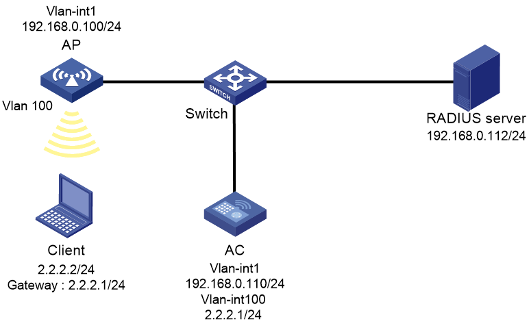
Prerequisites
Customize the authentication pages, compress them to a file, and upload the file to the root directory of the storage medium of the AC.
Configuring the RADIUS server
# Configure the RADIUS server correctly to provide authentication and accounting functions. (Details not shown.)
Configuring the AC
1. Assign IP addresses to interfaces and make sure the client, the AC, and the servers can reach each other. (Details not shown.)
2. Configure a RADIUS scheme:
# Create a RADIUS scheme named rs1 and enter its view.
<AC> system-view
[AC] radius scheme rs1
# Specify the primary authentication server and primary accounting server, and configure the keys for communication with the servers.
[AC-radius-rs1] primary authentication 192.168.0.112
[AC-radius-rs1] primary accounting 192.168.0.112
[AC-radius-rs1] key authentication simple radius
[AC-radius-rs1] key accounting simple radius
# Exclude the ISP domain name from the username sent to the RADIUS server.
[AC-radius-rs1] user-name-format without-domain
[AC-radius-rs1] quit
# Enable RADIUS session control.
[AC] radius session-control enable
3. Configure an authentication domain:
# Create an ISP domain named dm1 and enter its view.
[AC] domain dm1
# Configure AAA methods for the ISP domain.
[AC-isp-dm1] authentication portal radius-scheme rs1
[AC-isp-dm1] authorization portal radius-scheme rs1
[AC-isp-dm1] accounting portal radius-scheme rs1
[AC-isp-dm1] quit
# Configure domain dm1 as the default ISP domain. If a user enters the username without the ISP domain name at login, the authentication and accounting methods of the default domain are used for the user.
[AC] domain default enable dm1
4. Configure portal authentication:
# Configure a portal Web server.
[AC] portal web-server newpt
[AC-portal-websvr-newpt] url http://2.2.2.1:2331/portal
[AC-portal-websvr-newpt] quit
# Enable direct portal authentication on VLAN-interface 100.
[AC] interface vlan-interface 100
[AC–Vlan-interface100] portal enable method direct
# Specify portal Web server newpt on VLAN-interface 100.
[AC–Vlan-interface100] portal apply web-server newpt
[AC–Vlan-interface100] quit
# Create an HTTP-based local portal Web service and enter its view.
[AC] portal local-web-server http
# Specify file abc.zip as the default authentication page file for the local portal Web service. (Make sure the file exist under the root directory of the AC.)
[AC–portal-local-websvr-http] default-logon-page abc.zip
# Set the HTTP listening port number to 2331 for the local portal Web service.
[AC–portal-local-websvr-http] tcp-port 2331
[AC–portal-local-websvr-http] quit
Verifying the configuration
# Verify that the portal configuration has taken effect.
[AC] display portal interface vlan-interface 100
Portal information of Vlan-interface 100
VSRP instance: --
VSRP state: N/A
Authorization Strict checking
ACL Disabled
User profile Disabled
Dual stack : Disabled
Dual traffic-separate: Disabled
IPv4:
Portal status: Enabled
Portal authentication method: Direct
Portal Web server: newpt(active)
Secondary portal Web server: Not configured
Portal mac-trigger-server: Not configured
Authentication domain: Not configured
Pre-auth domain: Not configured
User-dhcp-only: Disabled
Pre-auth IP pool: Not configured
Max portal users: Not configured
Bas-ip: Not configured
User Detection: Not configured
Action for server detection:
Server type Server name Action
-- -- --
Layer3 source network:
IP address Mask
Destination authenticate subnet:
IP address Mask
IPv6:
Portal status: Disabled
Portal authentication method: Disabled
Portal Web server: Not configured
Secondary portal Web server: Not configured
Portal mac-trigger-server: Not configured
Authentication domain: Not configured
Pre-auth domain: Not configured
User-dhcp-only: Disabled
Pre-auth IP pool: Not configured
Max portal users: Not configured
Bas-ipv6: Not configured
User detection: Not configured
Action for server detection:
Server type Server name Action
-- -- --
Layer3 source network:
IP address Prefix length
Destination authenticate subnet:
IP address Prefix length
A user can perform portal authentication through a Web page. Before passing the authentication, the user can access only the authentication page http://2.2.2.1:2331/portal and all Web requests will be redirected to the authentication page. After passing the authentication, the user can access other network resources.
# After the user passes authentication, display information about the portal user.
[AC] display portal user interface vlan-interface 100
Total portal users: 1
Username: abc
Portal server: newpt
State: Online
VPN instance: --
MAC IP VLAN Interface
0015-e9a6-7cfe 2.2.2.2 -- Vlan-interface100
Authorization information:
IP pool: N/A
User profile: N/A
Session group profile: N/A
Example: Configuring remote MAC-based quick portal authentication
Network configuration
As shown in Figure 53, the client accesses the WLAN through the AP. The client is assigned a public IP address either manually or through DHCP. A portal server acts as a portal authentication server, a portal Web server, and a MAC binding server. A RADIUS server acts as the authentication/accounting server.
Configure remote MAC-based quick portal authentication to meet the following requirements:
· A user can access the network without portal authentication before the user's network traffic reaches 1024000 bytes.
· The client can pass portal authentication without entering a username or password after the user passes portal authentication for the first time.

Configuring the RADIUS server
# Configure the RADIUS server correctly to provide authentication and accounting functions. (Details not shown.)
Configuring the portal server
In this example, the portal server runs on IMC PLAT 7.1(E0303), IMC EIA 7.1(F0303), and IMC EIP 7.1(F0303).
1. Configure the portal authentication server:
a. Log in to IMC and click the User tab.
b. Select User Access Policy > Portal Service > Server from the navigation tree to open the portal server configuration page, as shown in Figure 54.
c. Configure the portal server parameters as needed.
This example uses the default values.
d. Click OK.
Figure 54 Portal authentication server configuration
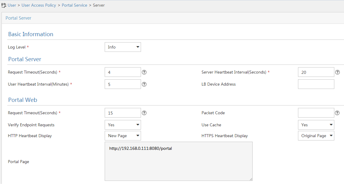
2. Configure the IP address group:
a. Select User Access Policy > Portal Service > IP Group from the navigation tree to open the portal IP address group configuration page.
b. Click Add to open the page as shown in Figure 55.
c. Enter the IP group name.
d. Enter the start IP address and end IP address of the IP group.
Make sure the client IP address (2.2.2.2) is in the IP group.
e. Select a service group.
This example uses the default group Ungrouped.
f. Select Normal from the Action list.
g. Click OK.
Figure 55 Adding an IP address group
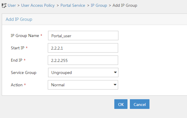
3. Add a portal device:
a. Select User Access Policy > Portal Service > Device from the navigation tree to open the portal device configuration page.
b. Click Add to open the page as shown in Figure 56.
c. Enter the device name.
d. Enter the IP address of the AC's interface connected to the client.
e. Set whether to support the portal server heartbeat and user heartbeat functions.
In this example, select No for both Support Server Heartbeat and Support User Heartbeat.
f. Enter the key, which must be the same as that configured on the AC.
g. Select Directly Connected for Access Method.
h. Click OK.
Figure 56 Adding a portal device

4. Associate the portal device with the IP address group:
a. As shown in Figure 57, click the Port Group Information Management icon for device NAS to open the port group configuration page.
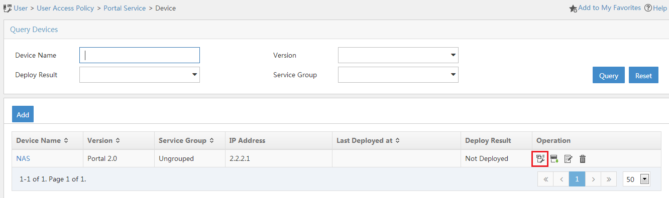
a. Click Add to open the page as shown in Figure 58.
b. Enter the port group name.
c. Select the configured IP address group.
The IP address used by the user to access the network must be within this IP address group.
d. Select Supported for Transparent Authentication.
e. Use the default settings for other parameters.
f. Click OK.
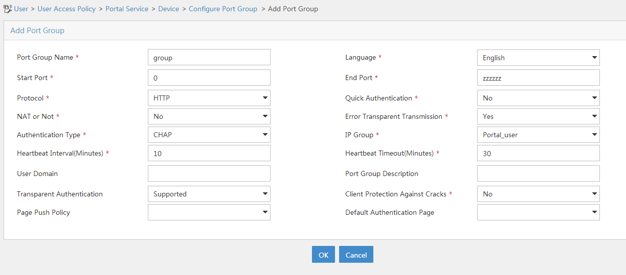
5. Select User Access Policy > Service Parameters > Validate System Configuration from the navigation tree to make the configurations take effect.
Configuring the MAC binding server
In this example, the MAC binding server runs on IMC PLAT 7.1(E0303), IMC EIA 7.1(F0303), and IMC EIP 7.1(F0303).
1. Add an access policy:
a. Select User Access Policy > Access Policy from the navigation tree to open the access policy page.
b. Click Add to open the page as shown in Figure 59.
c. Enter the access policy name.
d. Select a service group.
e. Use the default settings for other parameters.
f. Click OK.
Figure 59 Adding an access policy

2. Add an access service:
a. Select User Access Policy > Access Service from the navigation tree to open the access service page.
b. Click Add to open the page as shown in Figure 60.
c. Enter the service name.
d. Select the Transparent Authentication on Portal Endpoints option.
e. Use the default settings for other parameters.
f. Click OK.
Figure 60 Adding an access service
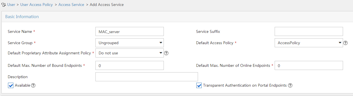
3. Add an access user:
a. Select Access User > All Access Users from the navigation tree to open the access user page.
b. Click Add to open the page as shown in Figure 61.
c. Select an access user.
d. Set the password.
e. Select a value from the Max. Transparent Portal Bindings list.
f. Click OK.
Figure 61 Adding an access user

4. Configure system parameters:
a. Select User Access Policy > Service Parameters > System Settings from the navigation tree to open the system settings page.
b. Click the Configure
icon ![]() for User Endpoint Settings to open the page as shown in Figure 62.
for User Endpoint Settings to open the page as shown in Figure 62.
c. Select whether to enable transparent portal authentication on non-smart devices.
In this example, select Enable for Non-Terminal Authentication.
d. Click OK.
Figure 62 Configuring user endpoint settings

a. Click the Configure
icon ![]() for Endpoint Aging Time to open the page as shown in Figure 63.
for Endpoint Aging Time to open the page as shown in Figure 63.
b. Set the endpoint aging time as needed.
This example uses the default value.
Figure 63 Setting the endpoint aging time

5. Select User Access Policy > Service Parameters > Validate System Configuration from the navigation tree to make the configurations take effect.
Configuring the AC
1. Assign IP addresses to interfaces and make sure the client, the AC, and the servers can reach each other. (Details not shown.)
2. Configure a RADIUS scheme:
# Create a RADIUS scheme named rs1 and enter its view.
<AC> system-view
[AC] radius scheme rs1
# Specify the primary authentication server and primary accounting server, and configure the keys for communication with the servers.
[AC-radius-rs1] primary authentication 192.168.0.112
[AC-radius-rs1] primary accounting 192.168.0.112
[AC-radius-rs1] key authentication simple radius
[AC-radius-rs1] key accounting simple radius
# Exclude the ISP domain name from the username sent to the RADIUS server.
[AC-radius-rs1] user-name-format without-domain
[AC-radius-rs1] quit
# Enable RADIUS session control.
[AC] radius session-control enable
3. Configure an authentication domain:
# Create an ISP domain named dm1 and enter its view.
[AC] domain dm1
# Configure AAA methods for the ISP domain.
[AC-isp-dm1] authentication portal radius-scheme rs1
[AC-isp-dm1] authorization portal radius-scheme rs1
[AC-isp-dm1] accounting portal radius-scheme rs1
[AC-isp-dm1] quit
# Configure domain dm1 as the default ISP domain. If a user enters the username without the ISP domain name at login, the authentication and accounting methods of the default domain are used for the user.
[AC] domain default enable dm1
4. Configure portal authentication:
# Configure a portal authentication server.
[AC] portal server newpt
[AC-portal-server-newpt] ip 192.168.0.111 key simple portal
[AC-portal-server-newpt] port 50100
[AC-portal-server-newpt] quit
# Configure a portal Web server.
[AC] portal web-server newpt
[AC-portal-websvr-newpt] url http://192.168.0.111:8080/portal
[AC-portal-websvr-newpt] quit
# Enable validity check on the wireless client.
[AC] portal host-check enable
# Create a service template named st1, set the SSID to st1, and create VLAN 100 on the service template.
[AC] wlan service-template st1
[AC-wlan-st-st1] ssid st1
[AC-wlan-st-st1] vlan 100
# Enable direct authentication on service template st1.
[AC–wlan-st-st1] portal enable method direct
# Specify the portal Web server newpt on service template st1.
[AC–wlan-st-st1] portal apply web-server newpt
# Configure the BAS-IP as 2.2.2.1 for portal packets sent from service template st1 to the portal authentication server.
[AC-wlan-st-st1] portal bas-ip 2.2.2.1
[AC-wlan-st-st1] quit
5. Configure MAC-based quick portal authentication:
# Create a MAC binding server named mts.
[AC] portal mac-trigger-server mts
# Set the free-traffic threshold for portal users to 1024000 bytes.
[AC-portal-mac-trigger-server-mts] free-traffic threshold 1024000
# Specify the IP address of the MAC binding server as 192.168.0.111.
[AC-portal-mac-trigger-server-mts] ip 192.168.0.111
[AC-portal-mac-trigger-server-mts] quit
# Specify MAC binding server mts on the service template st1.
[AC] wlan service-template st1
[AC-wlan-st-st1] portal apply mac-trigger-server mts
# Enable service template st1.
[AC-wlan-st-st1] service-template enable
[AC-wlan-st-st1] quit
Verifying the configuration
# Display information about the MAC binding server.
[AC] display portal mac-trigger-server name mts
Portal mac-trigger server: mts
Version : 1.0
Server type : IMC
IP : 192.168.0.111
Port : 50100
VPN instance : Not configured
Aging time : 300 seconds
Free-traffic threshold : 1024000 bytes
NAS-Port-Type : Not configured
Binding retry times : 3
Binding retry interval : 1 seconds
Authentication timeout : 3 minutes
A user can perform portal authentication by using the H3C iNode client or a Web browser. Before passing the authentication, the user can access only the authentication page http://192.168.0.111:8080/portal. All Web requests from the user will be redirected to the authentication page. After passing the authentication, the user can access other network resources.
For the first portal authentication, the user is required to enter the username and password. When the user goes offline and then accesses the network again, the user does not need to enter the authentication username and password.
# Display portal user information.
[AC] display portal user all
Total portal users: 1
Username: Client1
AP name: ap1
Radio ID: 1
SSID:st1
Portal server: newpt
State: Online
VPN instance: N/A
MAC IP VLAN Interface
0015-e9a6-7cfe 2.2.2.2 100 WLAN-BSS1/0/1
Authorization information:
DHCP IP pool: N/A
User profile: N/A
Session group profile: N/A
ACL number/name: N/A
CAR: N/A
Example: Configuring local MAC-based quick portal authentication
Network configuration
As shown in Figure 64, the client accesses the WLAN through the AP. The client is assigned a public IP address either manually or through DHCP. The AC acts as a portal authentication server, a portal Web server, and a MAC binding server.
Configure local MAC-based quick portal authentication to meet the following requirements:
· A user can access the network without portal authentication before the user's network traffic reaches 1024000 bytes.
· The client can pass portal authentication without entering a username or password within 24 hours after the user passes portal authentication for the first time.

Procedure
1. Assign IP addresses to interfaces and make sure the client, the AC, and the servers can reach each other. (Details not shown.)
2. Configure an authentication domain:
# Create an ISP domain named dm1.
<AC> system-view
[AC] domain dm1
# Configure local authentication, authorization, and accounting for portal users in ISP domain dm1.
[AC-isp-dm1] authentication portal local
[AC-isp-dm1] authorization portal local
[AC-isp-dm1] accounting portal local
[AC-isp-dm1] quit
# Configure ISP domain dm1 as the default ISP domain.
[AC] domain default enable dm1
3. Configure portal authentication:
# Create a portal Web server newpt and configure the URL for the portal Web server as http://192.168.0.111/portal.
[AC] portal web-server newpt
[AC-portal-websvr-newpt] url http://192.168.0.111/portal
[AC-portal-websvr-newpt] quit
# Enable validity check on wireless portal clients.
[AC] portal host-check enable
# Create a service template named st1.
[AC] wlan service-template st1
[AC-wlan-st-st1] ssid st1
# Enable direct IPv4 portal authentication on service template st1.
[AC-wlan-st-st1] portal enable method direct
# Specify portal Web server newpt on service template st1 for portal authentication.
[AC-wlan-st-st1] portal apply web-server newpt
[AC-wlan-st-st1] quit
4. Configure local MAC-based quick portal authentication:
# Create a MAC binding server named mts.
[AC] portal mac-trigger-server mts
# Enable local MAC-based quick portal authentication.
[AC-portal-mac-trigger-server-mts] local-binding enable
# Set the free-traffic threshold for portal users to 1024000 bytes.
[AC-portal-mac-trigger-server-mts] free-traffic threshold 1024000
# Set the aging time of local MAC-account binding entries to 24 hours.
[AC-portal-mac-trigger-server-mts] local-binding aging-time 24
[AC-portal-mac-trigger-server-mts] quit
# Specify MAC binding server mts for service template st1.
[AC] wlan service-template st1
[AC-wlan-st-st1] portal apply mac-trigger-server mts
# Enable service template st1.
[AC-wlan-st-st1] service-template enable
[AC-wlan-st-st1] quit
# Create an HTTP-based local portal Web service and enter its view.
[AC] portal local-web-server http
# Specify file default.zip as the default authentication page file for portal authentication. (Make sure that the file exists under the root directory of the AC.)
[AC–portal-local-websvr-http] default-logon-page default.zip
[AC–portal-local-websvr-http] quit
5. Configure a local user:
# Create a network access user named client1 and set the password for the user to password in plaintext form.
[AC] local-user client1 class network
[AC-luser-network-client1] password simple password
[AC-luser-network-client1] quit
Verifying the configuration
# Display information about MAC binding server mts.
[AC] display portal mac-trigger-server name mts
Portal mac-trigger server: mts
Version : 1.0
Server type : IMC
IP : 192.168.0.111
Port : 50100
VPN instance : Not configured
Aging time : 300 seconds
Free-traffic threshold : 1024000 bytes
NAS-Port-Type : Not configured
Binding retry times : 3
Binding retry interval : 1 seconds
Authentication timeout : 3 minutes
Local-binding : Enabled
Local-binding aging-time : 24 hours
aaa-fail nobinding : Disabled
Excluded attribute list : Not configured
Cloud-binding : Disabled
Cloud-server URL : Not configured
A user can perform portal authentication by using the H3C iNode client or a Web browser. Before passing the authentication, the user can access only the authentication page http://192.168.0.111/portal. All Web requests from the user will be redirected to the authentication page. After passing the authentication, the user can access other network resources.
For the first portal authentication, the user is required to enter the username and password. When the user goes offline and then accesses the network again, the user does not need to enter the authentication username and password.
# Display information about local MAC-account binding entries.
[AC] display portal local-binding mac-address all
Total mac-address number: 1
Mac-address User-name
0800-2700-b43a client1
# Display information about portal users on VLAN-interface 100.
[AC] display portal user interface vlan-interface100
Total portal users: 1
Username: client1
Portal server: N/A
State: Online
VPN instance: N/A
MAC IP VLAN Interface
0800-2700-b43a 192.168.0.56 100 WLAN-BSS1/0/1
Authorization information:
DHCP IP pool: N/A
User profile: N/A
Session group profile: N/A
ACL number/name: N/A
CAR: N/A
Example: Configuring cloud MAC-trigger authentication
Network configuration
As shown in Figure 65:
· The AC acts as the DHCP server to assign a private IP address to the client. The client uses the private IP address to perform portal authentication.
· The cloud server acts as the portal authentication server, the portal Web server, and the MAC binding server.
Configure cloud MAC-trigger authentication to meet the following requirements:
· A user can access only the portal Web server before passing portal authentication.
· A user can access the network resources after passing portal authentication. The user can pass portal authentication without entering a username or password when the user tries to come online again.

Configuring the cloud server
# On the Oasis platform, enable Auth free for reconnect on the authentication template for the AC. (Details not shown.)
Configuring the AC
1. Assign IP addresses to interfaces and make sure the client, AC, and servers can reach each other. (Details not shown.)
2. Configure basic network functions:
# Create VLAN 100. The client will access the wireless network through VLAN 100.
<AC> system-view
[AC] vlan 100
[AC-vlan100] quit
# Assign IP addresses to the VLAN interface. (Details not shown.)
# Enable DNS proxy.
[AC] dns proxy enable
# Enable DHCP.
[AC] dhcp enable
# Create a DHCP address pool named client.
[AC] dhcp server ip-pool client
# Configure DHCP address pool client to assign IP addresses to clients from subnet 192.168.100.0/24.
[AC-dhcp-pool-client] network 192.168.100.0 mask 255.255.255.0
# Exclude IP address 192.168.100.1 from dynamic allocation.
[AC-dhcp-pool-client] forbidden-ip 192.168.100.1
# Specify 192.168.100.1 as the gateway address.
[AC-dhcp-pool-client] gateway-list 192.168.100.1
# Specify 192.168.100.1 as the DNS server address.
[AC-dhcp-pool-client] dns-list 192.168.100.1
[AC-dhcp-pool-client] quit
# Apply DHCP address pool client to VLAN-interface 100.
[AC] interface vlan-interface 100
[AC-Vlan-interface100] dhcp server apply ip-pool client
[AC-Vlan-interface100] quit
3. Configure an ISP domain:
# Create an ISP domain named cloud.
[AC] domain cloud
# Configure the AC not to perform authentication, authorization, or accounting on portal users.
[AC-isp-cloud] authentication portal none
[AC-isp-cloud] authorization portal none
[AC-isp-cloud] accounting portal none
[AC-isp-cloud] quit
4. Configure cloud MAC-trigger authentication:
# Create a portal Web server named wbs.
[AC] portal web-server wbs
# Specify http:// lvzhoutest.h3c.com/portal/protocol as the URL of portal Web server wbs.
[AC-portal-websvr-wbs] url http://lvzhoutest.h3c.com/portal/protocol
# Specify the type of the portal Web server as oauth.
[AC-portal-websvr-wbs] server-type oauth
# Enable the portal captive-bypass feature.
[AC-portal-websvr-wbs] captive-bypass enable
[AC-portal-websvr-wbs] quit
# Enable cloud MAC-trigger authentication.
[AC] portal mac-trigger-server abc
[AC-portal-extend-auth-server-abc] cloud-binding enable
# Specify http://lvzhoutest.h3c.com as the URL of the cloud portal authentication server.
[AC-portal-extend-auth-server-abc] cloud-server url http://lvzhoutest.h3c.com
[AC-portal-extend-auth-server-abc] quit
# Create a service template named st1.
[AC] wlan service-template st1
# Assign clients coming online through service template st1 to VLAN 100.
[AC-wlan-st-st1] vlan 100
# Set the SSID of service template st1 to cloud.
[AC-wlan-st-st1] ssid cloud
# Enable direct portal authentication on service template st1.
[AC-wlan-st-st1] portal enable method direct
# Specify ISP domain cloud as the portal authentication domain.
[AC-wlan-st-st1] portal extend-auth domain extend-auth
# Specify portal Web server wbs on service template st1.
[AC-wlan-st-st1] portal apply web-server wbs
# Specify MAC binding server abc on service template st1.
[AC-wlan-st-st1] portal apply mac-trigger-server abc
# Enable portal temporary pass and set the temporary pass period to 60 seconds.
[AC-wlan-st-st1] portal temp-pass period 60 enable
# Enable service template st1.
[AC-wlan-st-st1] service-template enable
[AC-wlan-st-st1] quit
# Create AP lvzhou-ap with model WA2620i-AGN, and set its serial ID to 219801A0CNC123001072.
[AC] wlan ap lvzhou-ap model WA2620i-AGN
[AC-wlan-ap-lvzhou-ap] serial-id 219801A0CNC123001072
# Enter the view of radio 1.
[AC-wlan-ap-ap1] radio 1
# Bind service template st1 to radio 1.
[AC-wlan-ap-ap1-radio-1] service-template st1
# Enable radio 1.
[AC-wlan-ap-ap1-radio-1] radio enable
[AC-wlan-ap-ap1-radio-1] quit
[AC-wlan-ap-ap1] quit
# Configure destination-based portal-free rules 1 and 2 to allow portal users to access the DNS service without authentication.
[AC] portal free-rule 1 destination ip any udp 53
[AC] portal free-rule 2 destination ip any tcp 53
# Configure a temporary pass rule to allow user packets that access the page http://lvzhoutest.h3c.com to pass within the temporary pass period.
[AC] temp-pass if-match original-url http://lvzhoutest.h3c.com
Verifying the configuration
# Display packet statistics for the cloud portal authentication server.
[AC] display portal packet statistics extend-auth-server cloud
Extend-auth server : cloud
Pkt-Type Success Error Timeout Conn-failure
REQ_ACCESSTOKEN 1 0 0 0
REQ_USERINFO 1 0 0 0
RESP_ACCESSTOKEN 1 0 0 0
RESP_USERINFO 1 0 0 0
POST_ONLINEDATA 10 0 0 0
RESP_ONLINEDATA 10 0 0 0
POST_OFFLINEUSER 1 0 0 0
REPORT_ONLINEUSER 2 0 0 0
REQ_CLOUDBIND 2 0 0 0
ESP_CLOUDBIND 2 0 0 0
REQ_BINDUSERINFO 1 0 0 0
RESP_BINDUSERINFO 1 0 0 0
AUTHENTICATION 2 0 0 0
Before passing portal authentication, a user can access only the portal authentication page http://lvzhoutest.h3c.com/portal/protocol. All Web requests from the user will be redirected to the portal authentication page. After passing portal authentication, the user can access other network resources.
The user needs to enter the username and password for the first authentication. If the user goes offline and then tries to come online, the user can directly access the network resources without entering the username and password.
# Display information about all portal users.
[AC] display portal user all
Total portal users: 1
Username: client1
AP name: lvzhou-ap
Radio ID: 2
SSID: WXauth
Portal server: N/A
State: Online
VPN instance: N/A
MAC IP VLAN Interface
582a-f776-8050 192.168.100.3 100 WLAN-BSS2/0/5
Authorization information:
DHCP IP pool: N/A
User profile: N/A
Session group profile: N/A
ACL number/name: N/A
Inbound CAR: N/A
Outbound CAR: N/A
Example: Configuring portal support for QQ authentication
Network configuration
As shown in Figure 66, the AC acts as the DHCP server to assign a private IP address to the client. The client uses the private IP address to perform QQ authentication.
Configure portal support for QQ authentication to meet the following requirements:
· The client can access only the QQ authentication server before passing QQ authentication.
· The client can access other network resources after passing QQ authentication.

Prerequisites
Edit portal authentication pages, and add the QQ authentication button to the logon page. Compress the authentication pages to a .zip file, and save the authentication page file to the root directory of the AC. This example uses file abc.zip.
Procedure
1. Assign IP addresses to interfaces and make sure the client, the AC, and the QQ server can reach each other. (Details not shown.)
2. Configure basic network functions:
# Create VLAN 100. The client will access the wireless network through VLAN 100.
<AC> system-view
[AC] vlan 100
[AC-vlan100] quit
# Create VLAN 200. The AC will use this VLAN for NAT and to obtain a public IP address through DHCP.
[AC] vlan 200
[AC-vlan200] quit
# Assign IP addresses to VLAN interfaces. (Details not shown.)
# Enable DNS proxy.
[AC] dns proxy enable
# Map IP address 192.168.1.1 to the domain name of the portal Web server lvzhou.h3c.com.
[AC] ip host lvzhou.h3c.com 192.168.1.1
# Enable DHCP.
[AC] dhcp enable
# Create a DHCP address pool named client.
[AC] dhcp server ip-pool client
# Configure DHCP address pool client to assign IP addresses to clients from subnet 192.168.1.0/24.
[AC-dhcp-pool-client] network 192.168.1.0 mask 255.255.255.0
# Exclude IP address 192.168.1.1.1 from dynamic allocation.
[AC-dhcp-pool-client] forbidden-ip 192.168.1.1
# Specify 192.168.1.1 as the gateway address.
[AC-dhcp-pool-client] gateway-list 192.168.1.1
# Specify 192.168.1.1 as the DNS server address.
[AC-dhcp-pool-client] dns-list 192.168.1.1
[AC-dhcp-pool-client] quit
# Apply DHCP address pool client to VLAN-interface 100.
[AC] interface vlan-interface 100
[AC-Vlan-interface100] dhcp server apply ip-pool client
[AC-Vlan-interface100] quit
# Configure ACL 2000, and create a rule to permit packets only from subnet 192.168.1.0/24 to pass through.
[AC] acl basic 2000
[AC-acl-ipv4-basic-2000] rule permit source 192.168.1.0 0.0.0.255
[AC-acl-ipv4-basic-2000] quit
# Configure VLAN-interface 200 to use DHCP for IP address acquisition.
[AC] interface vlan-interface 200
[AC-Vlan-interface200] ip address dhcp-alloc
# Enable outbound NAT with Easy IP on interface VLAN-interface 200.
[AC-Vlan-interface200] nat outbound 2000
3. Configure an authentication domain:
# Create an ISP domain named extend-auth.
[AC] domain extend-auth
# Configure the device not to perform authentication, authorization, or accounting for portal users.
[AC-isp-extend-auth] authentication portal none
[AC-isp-extend-auth] authorization portal none
[AC-isp-extend-auth] accounting portal none
[AC-isp-extend-auth] quit
4. Configure QQ authentication:
# Specify http:// 192.168.1.1/portal as the URL of the portal Web server.
[AC] portal web-server wbs
[AC-portal-websvr-wbs] url http://192.168.1.1/portal
[AC-portal-websvr-wbs] quit
# Create a QQ authentication server.
[AC] portal extend-auth-server qq
[AC-portal-extend-auth-server-qq] quit
# Create a service template named st1.
[AC] wlan service-template st1
# Assign clients coming online through service template st1 to VLAN 100.
[AC-wlan-st-st1] vlan 100
# Set the SSID of service template st1 to service.
[AC-wlan-st-st1] ssid service
# Enable direct portal authentication on service template st1.
[AC-wlan-st-st1] portal enable method direct
# Specify ISP domain extend-auth as the authentication domain for QQ authentication.
[AC-wlan-st-st1] portal extend-auth domain extend-auth
# Specify portal Web server wbs on service template st1.
[AC-wlan-st-st1] portal apply web-server wbs
# Enable service template st1.
[AC-wlan-st-st1] service-template enable
[AC-wlan-st-st1] quit
# Create AP ap1 with model WA4320i-CAN, and set its serial ID to 210235A29G007C000020..
[AC] wlan ap ap1 model WA4320i-ACN
[AC-wlan-ap-ap1] serial-id 210235A29G007C000020
# Enter the view of radio 1.
[AC-wlan-ap-ap1] radio 1
# Bind service template st1 to radio 1.
[AC-wlan-ap-ap1-radio-1] service-template st1
# Enable radio 1.
[AC-wlan-ap-ap1-radio-1] radio enable
[AC-wlan-ap-ap1-radio-1] quit
[AC-wlan-ap-ap1] quit
# Create an HTTP-based local portal Web service and enter its view.
[AC] portal local-web-server http
# Specify the file abc.zip as the default authentication page file for local portal authentication. . (Make sure that the file exists under the root directory of the AC.)
[AC-portal-local-websvr-http] default-logon-page abc.zip
[AC-portal-local-websvr-http] quit
# Configure destination-based portal-free rules 1 and 2 to allow portal users to access the DNS service without authentication.
[AC] portal free-rule 1 destination ip any udp 53
[AC] portal free-rule 2 destination ip any tcp 53
# Configure destination-based portal-free rules 3 and 4 to allow portal users to access the QQ authentication server without authentication.
[AC] portal free-rule 3 destination *.qq.com
[AC] portal free-rule 4 destination *.gtimg.cn
Verifying the configuration
# Display information about the QQ authentication server.
[AC] display portal extend-auth-server all
Portal extend-auth-server: qq
Authentication URL : https://graph.qq.com
APP ID : 101235509
APP key : ******
Redirect URL : http://oauthindev.h3c.com/portal/qqlogin.html
Before passing the authentication, a user can access only the portal authentication page http://192.168.0.111/portal. All Web requests from the user will be redirected to the portal authentication page. After clicking the QQ authentication button on the portal authentication page, the user is redirected to the QQ authentication page. After passing QQ authentication, the user can access other network resources.
# Display information about all portal users.
[AC] display portal user all
Total portal users: 1
Username: 00-00-00-00-00-01
AP name: ap1
Radio ID: 1
SSID:service
Portal server: N/A
State: Online
VPN instance: N/A
MAC IP VLAN Interface
0015-e9a6-7cfe 192.168.1.2 100 WLAN-BSS1/0/1
Authorization information:
DHCP IP pool: N/A
User profile: N/A
Session group profile: N/A
ACL number/name: N/A
CAR: N/A
Example: Configuring portal support for email authentication
Network configuration
As shown in Figure 67, the AC acts as the DHCP server to assign a private IP address to the client. The client uses the private IP address to perform email authentication.
Configure portal support for email authentication to meet the following requirements:
· The client can access only the email authentication server before passing the authentication.
· The client can access other network resources after passing the authentication.

Prerequisites
Edit portal authentication pages and the email authentication page, and add the email authentication button to the portal logon page. Compress the authentication pages to a .zip file, and save the authentication page file to the root directory of the AC. This example uses file abc.zip.
Procedure
1. Assign IP addresses to interfaces and make sure the client, the AC, and the mail server can reach each other. (Details not shown.)
2. Configure basic network functions:
# Create VLAN 100. The client will access the wireless network through VLAN 100.
<AC> system-view
[AC] vlan 100
[AC-vlan100] quit
# Create VLAN 200. The AC will use VLAN 200 for NAT and to obtain a public network address through DHCP.
[AC] vlan 200
[AC-vlan200] quit
# Assign IP addresses to VLAN interfaces. (Details not shown.)
# Enable DNS proxy.
[AC] dns proxy enable
# Configure a mapping between the domain name of the portal Web server www.mail.com and IP address 192.168.1.1.
[AC] ip host www.mail.com 192.168.1.1
# Enable DHCP.
[AC] dhcp enable
# Create DHCP address pool named client.
[AC] dhcp server ip-pool client
# Configure DHCP address pool client to assign IP addresses to clients from subnet 192.168.1.0/24.
[AC-dhcp-pool-client] network 192.168.1.0 mask 255.255.255.0
# Exclude IP address 192.168.1.1 from dynamic allocation.
[AC-dhcp-pool-client] forbidden-ip 192.168.1.1
# Specify 192.168.1.1 as the gateway address.
[AC-dhcp-pool-client] gateway-list 192.168.1.1
# Specify 192.168.1.1 as the DNS server address.
[AC-dhcp-pool-client] dns-list 192.168.1.1
[AC-dhcp-pool-client] quit
# Apply DHCP address pool client to VLAN-interface 100.
[AC] interface vlan-interface 100
[AC-Vlan-interface100] dhcp server apply ip-pool client
[AC-Vlan-interface100] quit
# Configure ACL 2000, and create a rule to permit packets only from subnet 192.168.1.0/24 to pass through.
[AC] acl basic 2000
[AC-acl-ipv4-basic-2000] rule permit source 192.168.1.0 0.0.0.255
[AC-acl-ipv4-basic-2000] quit
# Configure VLAN-interface 200 to use DHCP for IP address acquisition.
[AC] interface vlan-interface 200
[AC-Vlan-interface200] ip address dhcp-alloc
# Enable outbound NAT with Easy IP on interface VLAN-interface 200.
[AC-Vlan-interface200] nat outbound 2000
[AC-Vlan-interface200] quit
3. Configure an ISP domain:
# Create an ISP domain named extend-auth.
[AC] domain extend-auth
# Configure the AC not to perform authentication, authorization, or accounting for portal users.
[AC-isp-extend-auth] authentication portal none
[AC-isp-extend-auth] authorization portal none
[AC-isp-extend-auth] accounting portal none
[AC-isp-extend-auth] quit
4. Configure email authentication:
# Specify https:// 192.168.1.1/portal as the URL of portal Web server wbs.
[AC] portal web-server wbs
[AC-portal-websvr-wbs] url https://192.168.1.1/portal
[AC-portal-websvr-wbs] quit
# Create an email authentication server.
[AC] portal extend-auth-server mail
# Specify POP3 and IMAP as protocols for email authentication.
[AC-portal-extend-auth-server-mail] mail-protocol pop3 imap
[AC-portal-extend-auth-server-mail] quit
# Create a service template named st1.
[AC] wlan service-template st1
# Assign clients coming online through service template st1 to VLAN 100.
[AC-wlan-st-st1] vlan 100
# Set the SSID of service template st1 to service.
[AC-wlan-st-st1] ssid service
# Enable direct portal authentication on service template st1.
[AC-wlan-st-st1] portal enable method direct
# Specify ISP domain extend-auth as the authentication domain for email authentication.
[AC-wlan-st-st1] portal extend-auth domain extend-auth
# Specify portal Web server wbs on service template st1.
[AC-wlan-st-st1] portal apply web-server wbs
# Enable service template st1.
[AC-wlan-st-st1] service-template enable
[AC-wlan-st-st1] quit
# Create AP ap1 with model WA4320i-CAN, and set its serial ID to 210235A29G007C000020.
[AC] wlan ap ap1 model WA4320i-ACN
[AC-wlan-ap-ap1] serial-id 210235A29G007C000020
# Enter the view of radio 1.
[AC-wlan-ap-ap1] radio 1
# Bind service template st1 to radio 1.
[AC-wlan-ap-ap1-radio-1] service-template st1
# Enable radio 1.
[AC-wlan-ap-ap1-radio-1] radio enable
[AC-wlan-ap-ap1-radio-1] quit
[AC-wlan-ap-ap1] quit
# Create an HTTPS-based local portal Web service and enter its view.
[AC] portal local-web-server https
# Specify the file abc.zip as the default authentication page file for local portal authentication. (Make sure that the file exists under the root directory of the AC.)
[AC-portal-local-websvr-https] default-logon-page abc.zip
[AC-portal-local-websvr-https] quit
# Configure destination-based portal-free rules 1 and 2 to allow portal users to access the DNS service without authentication.
[AC] portal free-rule 1 destination ip any udp 53
[AC] portal free-rule 2 destination ip any tcp 53
Verifying the configuration
# Display information about the email authentication server.
[AC] display portal extend-auth-server mail
Portal extend-auth-server: mail
Mail protocol : POP3 IMAP
Before passing the authentication, a user can access only the portal authentication page http://192.168.0.111/portal. All Web requests from the user will be redirected to the portal authentication page. After the user clicking the email authentication button on the portal authentication page, the user is redirected to the email authentication page. After passing the email authentication, the user can access other network resources.
# Display information about all portal users.
[AC] display portal user all
Total portal users: 1
Username: user
AP name: ap1
Radio ID: 1
SSID:service
Portal server: N/A
State: Online
VPN instance: N/A
MAC IP VLAN Interface
0015-e9a6-7cfe 192.168.1.2 100 WLAN-BSS1/0/1
Authorization information:
DHCP IP pool: N/A
User profile: N/A
Session group profile: N/A
ACL number/name: N/A
CAR: N/A
Portal configuration examples (on fat APs)
Example: Configuring direct portal authentication
Network configuration
As shown in Figure 68, the client accesses the WLAN through the AP.
Configure direct portal authentication, so the client can access only the portal server before passing the authentication and can access other network resources after passing the authentication.

Configuring the RADIUS server
# Configure the RADIUS server correctly to provide authentication and accounting functions. (Details not shown.)
Configuring the portal authentication server
In this example, the portal server runs on IMC PLAT 5.0(E0101) and IMC UAM 5.0(E0101).
1. Configure the portal authentication server:
a. Log in to IMC and click the Service tab.
b. Select User Access Manager > Portal Service Management > Server from the navigation tree to open the portal server configuration page, as shown in Figure 69.
c. Configure the portal server parameters as needed.
This example uses the default settings.
d. Click OK.
Figure 69 Portal server configuration
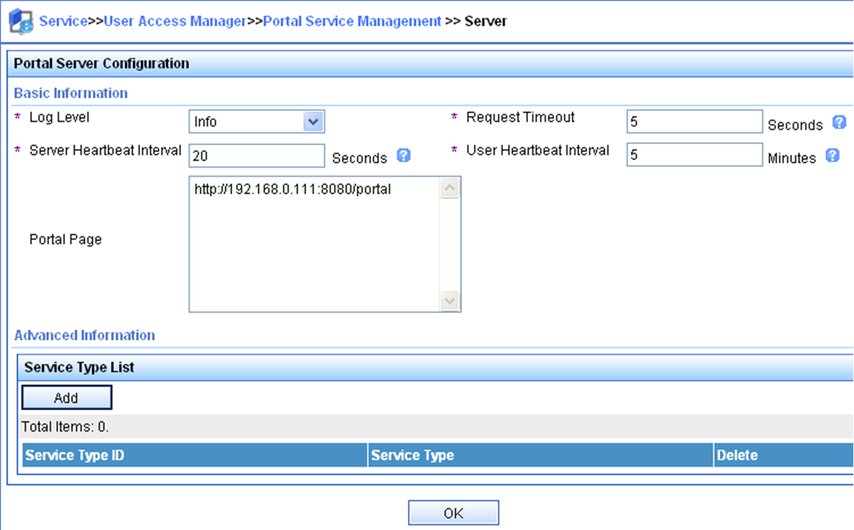
2. Configure the IP address group:
a. Select User Access Manager > Portal Service Management > IP Group from the navigation tree to open the portal IP address group configuration page.
b. Click Add to open the page as shown in Figure 70.
c. Enter the IP group name.
d. Enter the start IP address and end IP address of the IP group.
Make sure the client IP address is in the IP group.
e. Select a service group.
This example uses the default group Ungrouped.
f. Select the action Normal.
g. Click OK.
Figure 70 Adding an IP address group

3. Add a portal device:
a. Select User Access Manager > Portal Service Management > Device from the navigation tree to open the portal device configuration page.
b. Click Add to open the page as shown in Figure 71.
c. Enter the device name NAS.
d. Enter the IP address of the interface through which the AP connects to the client.
e. Enter the key, which must be the same as that configured on the AP.
f. Set whether to enable IP address reallocation.
This example uses direct portal authentication, and therefore select No from the Reallocate IP list.
g. Select whether to support sever heartbeat and user heartbeat functions.
In this example, select No for both Support Server Heartbeat and Support User Heartbeat.
h. Click OK.
Figure 71 Adding a portal device
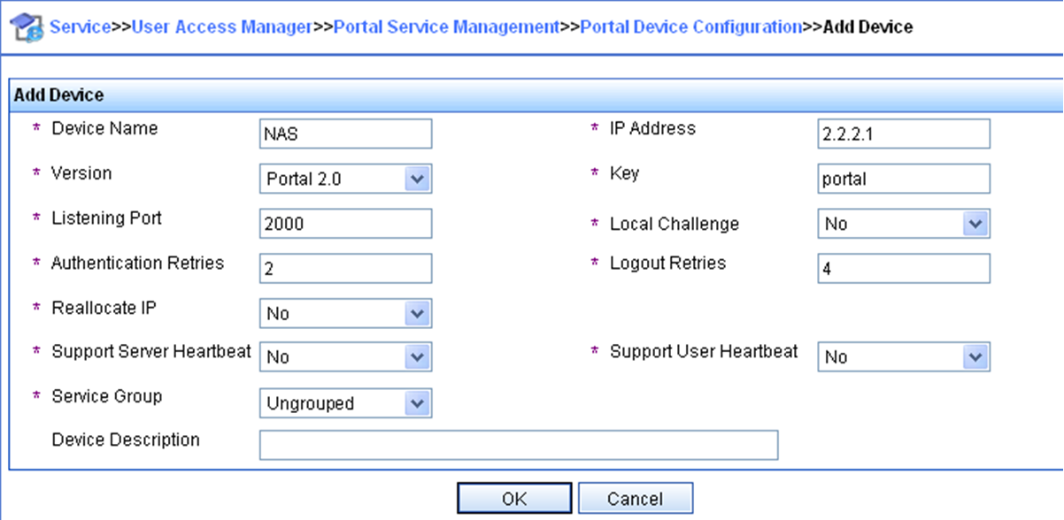
4. Associate the portal device with the IP address group:
a. As shown in Figure 72, click the icon in the Port Group Information Management column of device NAS to open the port group configuration page.
b. Click Add to open the page as shown in Figure 73.
c. Enter the port group name.
d. Select the configured IP address group.
The IP address used by the user to access the network must be within this IP address group.
e. Use the default settings for other parameters.
f. Click OK.


5. Select User Access Manager > Service Parameters > Validate System Configuration from the navigation tree to make the configurations take effect.
Configuring the AP
1. Assign IP addresses to interfaces and make sure the client, the AP, and the servers can reach each other. (Details not shown.)
2. Configure a RADIUS scheme:
# Create a RADIUS scheme named rs1 and enter its view.
<AP> system-view
[AP] radius scheme rs1
# Specify the primary authentication server and primary accounting server, and configure the keys for communication with the servers.
[AP-radius-rs1] primary authentication 192.168.0.112
[AP-radius-rs1] primary accounting 192.168.0.112
[AP-radius-rs1] key authentication simple radius
[AP-radius-rs1] key accounting simple radius
# Exclude the ISP domain name from the username sent to the RADIUS server.
[AP-radius-rs1] user-name-format without-domain
[AP-radius-rs1] quit
# Enable RADIUS session control.
[AP] radius session-control enable
3. Configure an authentication domain:
# Create an ISP domain named dm1 and enter its view.
[AP] domain dm1
# Configure AAA methods for the ISP domain.
[AP-isp-dm1] authentication portal radius-scheme rs1
[AP-isp-dm1] authorization portal radius-scheme rs1
[AP-isp-dm1] accounting portal radius-scheme rs1
[AP-isp-dm1] quit
# Configure domain dm1 as the default ISP domain. If a user enters the username without the ISP domain name at login, the authentication and accounting methods of the default domain are used for the user.
[AP] domain default enable dm1
4. Configure portal authentication:
# Configure a portal authentication server.
[AP] portal server newpt
[AP-portal-server-newpt] ip 192.168.0.111 key simple portal
[AP-portal-server-newpt] port 50100
[AP-portal-server-newpt] quit
# Configure a portal Web server.
[AP] portal web-server newpt
[AP-portal-websvr-newpt] url http://192.168.0.111:8080/portal
[AP-portal-websvr-newpt] quit
# Enable direct portal authentication on VLAN-interface 100.
[AP] interface vlan-interface 100
[AP–Vlan-interface100] portal enable method direct
# Specify portal Web server newpt on VLAN-interface 100.
[AP–Vlan-interface100] portal apply web-server newpt
# Configure the BAS-IP as 2.2.2.1 for portal packets sent from VLAN-interface 100 to the portal authentication server.
[AP–Vlan-interface100] portal bas-ip 2.2.2.1
[AP–Vlan-interface100] quit
Verifying the configuration
# Verify that the portal configuration has taken effect.
[AP] display portal interface vlan-interface 100
Portal information of Vlan-interface100
NAS-ID profile: Not configured
Authorization : Strict checking
ACL : Disabled
User profile : Disabled
Dual stack : Disabled
Dual traffic-separate: Disabled
IPv4:
Portal status: Enabled
Portal authentication type: Direct
Portal Web server: newpt(active)
Secondary portal Web server: Not configured
Portal mac-trigger-server: Not configured
Authentication domain: Not configured
Pre-auth domain: Not configured
Extend-auth domain: Not configured
User-dhcp-only: Disabled
Pre-auth IP pool: Not configured
Max portal users: Not configured
Bas-ip: 2.2.2.1
User detection: Not configured
Portal temp-pass: Disabled
Action for server detection:
Server type Server name Action
-- -- --
Destination authenticate subnet:
IP address Mask
IPv6:
Portal status: Disabled
Portal authentication type: Disabled
Portal Web server: Not configured(active)
Secondary portal Web server: Not configured
Portal mac-trigger-server: Not configured
Authentication domain: Not configured
Pre-auth domain: Not configured
Extend-auth domain: Not configured
User-dhcp-only: Disabled
Pre-auth IP pool: Not configured
Max portal users: Not configured
Bas-ipv6: Not configured
User detection: Not configured
Portal temp-pass: Disabled
Action for server detection:
Server type Server name Action
-- -- --
Destination authenticate subnet:
IP address Prefix length
A user can perform portal authentication by using the H3C iNode client or a Web browser. Before passing the authentication, the user can access only the authentication page http://192.168.0.111:8080/portal. All Web requests from the user will be redirected to the authentication page. After passing the authentication, the user can access other network resources.
# After the user passes authentication, display information about the portal user.
[AP] display portal user interface vlan-interface 100
Total portal users: 1
Username: abc
Portal server: newpt
State: Online
VPN instance: N/A
MAC IP VLAN Interface
0015-e9a6-7cfe 2.2.2.2 100 Vlan-interface100
Authorization information:
DHCP IP pool: N/A
User profile: N/A
Session group profile: N/A
ACL: N/A
CAR: N/A
Inbound CAR: N/A
Outbound CAR: N/A
Example: Configuring extended direct portal authentication
Network configuration
As shown in Figure 74, the client accesses the WLAN through the AP.
Configure extended direct portal authentication. If the client fails security check after passing identity authentication, it can access only subnet 192.168.0.0/24. After passing security check, the client can access other network resources.

Configuring the RADIUS server
# Configure the RADIUS server correctly to provide authentication and accounting functions. (Details not shown.)
Configuring the AP
1. Assign IP addresses to interfaces and make sure the client, the AP, and the servers can reach each other. (Details not shown.)
2. Configure a RADIUS scheme:
# Create a RADIUS scheme named rs1 and enter its view.
<AP> system-view
[AP] radius scheme rs1
# Specify the primary authentication server and primary accounting server, and configure the keys for communication with the servers.
[AP-radius-rs1] primary authentication 192.168.0.112
[AP-radius-rs1] primary accounting 192.168.0.112
[AP-radius-rs1] key accounting simple radius
[AP-radius-rs1] key authentication simple radius
# Exclude the ISP domain name from the username sent to the RADIUS server.
[AP-radius-rs1] user-name-format without-domain
# Specify the security policy server.
[AP-radius-rs1] security-policy-server 192.168.0.113
[AP-radius-rs1] quit
# Enable RADIUS session control.
[AP] radius session-control enable
3. Configure an authentication domain:
# Create an ISP domain named dm1 and enter its view.
[AP] domain dm1
# Configure AAA methods for the ISP domain.
[AP-isp-dm1] authentication portal radius-scheme rs1
[AP-isp-dm1] authorization portal radius-scheme rs1
[AP-isp-dm1] accounting portal radius-scheme rs1
[AP-isp-dm1] quit
# Configure domain dm1 as the default ISP domain. If a user enters the username without the ISP domain name at login, the authentication and accounting methods of the default domain are used for the user.
[AP] domain default enable dm1
4. Configure ACL 3000 as the isolation ACL and ACL 3001 as the security ACL.
[AP-acl-ipv4-adv-3000] rule permit ip destination 192.168.0.0 0.0.0.255
[AP-acl-ipv4-adv-3000] rule deny ip
[AP-acl-ipv4-adv-3000] quit
[AP] acl advanced 3001
[AP-acl-ipv4-adv-3001] rule permit ip
[AP-acl-ipv4-adv-3001] quit
|
|
NOTE: Make sure you specify ACL 3000 as the isolation ACL and ACL 3001 as the security ACL on the security policy server. |
5. Configure portal authentication:
# Configure a portal authentication server.
[AP] portal server newpt
[AP-portal-server-newpt] ip 192.168.0.111 key simple portal
[AP-portal-server-newpt] port 50100
[AP-portal-server-newpt] quit
# Configure a portal Web server.
[AP] portal web-server newpt
[AP-portal-websvr-newpt] url http://192.168.0.111:8080/portal
[AP-portal-websvr-newpt] quit
# Enable direct portal authentication on VLAN-interface 100.
[AP] interface vlan-interface 100
[AP–Vlan-interface100] portal enable method direct
# Specify portal Web server newpt on VLAN-interface 100.
[AP–Vlan-interface100] portal apply web-server newpt
# Configure the BAS-IP as 2.2.2.1 for portal packets sent from VLAN-interface 100 to the portal authentication server.
[AP–Vlan-interface100] portal bas-ip 2.2.2.1
[AP–Vlan-interface100] quit
Verifying the configuration
# Verify that the portal configuration has taken effect.
[AP] display portal interface vlan-interface 100
Portal information of Vlan-interface100
NAS-ID profile: Not configured
Authorization : Strict checking
ACL : Disabled
User profile : Disabled
Dual stack : Disabled
Dual traffic-separate: Disabled
IPv4:
Portal status: Enabled
Portal authentication type: Direct
Portal Web server: newpt(active)
Secondary portal Web server: Not configured
Portal mac-trigger-server: Not configured
Authentication domain: Not configured
Pre-auth domain: Not configured
Extend-auth domain: Not configured
User-dhcp-only: Disabled
Pre-auth IP pool: Not configured
Max portal users: Not configured
Bas-ip: 2.2.2.1
User detection: Not configured
Portal temp-pass: Disabled
Action for server detection:
Server type Server name Action
-- -- --
Destination authenticate subnet:
IP address Mask
IPv6:
Portal status: Disabled
Portal authentication type: Disabled
Portal Web server: Not configured
Secondary portal Web server: Not configured
Portal mac-trigger-server: Not configured
Authentication domain: Not configured
Pre-auth domain: Not configured
Extend-auth domain: Not configured
User-dhcp-only: Disabled
Pre-auth IP pool: Not configured
Max portal users: Not configured
Bas-ipv6: Not configured
User detection: Not configured
Portal temp-pass: Disabled
Action for server detection:
Server type Server name Action
-- -- --
Destination authenticate subnet:
IP address Prefix length
Before passing portal authentication, a user that uses the H3C iNode client can access only the authentication page http://192.168.0.111:8080/portal. All Web requests from the user will be redirected to the authentication page.
· The user can access the resources permitted by ACL 3000 after passing only identity authentication.
· The user can access network resources permitted by ACL 3001 after passing both identity authentication and security check.
# After the user passes identity authentication and security check, display information about the portal user.
[AP] display portal user interface vlan-interface 100
Total portal users: 1
Username: abc
Portal server: newpt
State: Online
VPN instance: N/A
MAC IP VLAN Interface
0015-e9a6-7cfe 2.2.2.2 100 Vlan-interface100
Authorization information:
DHCP IP pool: N/A
User profile: N/A
Session group profile: N/A
ACL: 3001
CAR: N/A
Inbound CAR: N/A
Outbound CAR: N/A
Example: Configuring portal server detection and portal user synchronization
Network configuration
As shown in Figure 75, the client accesses the WLAN through the AP and obtains a public IP address either manually or through DHCP. A portal server acts as both a portal authentication server and a portal Web server. A RADIUS server acts as the authentication/accounting server.
· Configure direct portal authentication on the AP, so the client can access only the portal server before passing the authentication and can access other network resources after passing the authentication.
· Configure the AP to detect the reachability state of the portal authentication server, send log messages upon state changes, and disable portal authentication when the authentication server is unreachable.
· Configure the AP to synchronize portal user information with the portal server periodically.

Configuring the RADIUS server
# Configure the RADIUS server correctly to provide authentication and accounting functions. (Details not shown.)
Configuring the portal authentication server
In this example, the portal server runs on IMC PLAT 5.0(E0101) and IMC UAM 5.0(E0101).
1. Configure the portal authentication server:
a. Log in to IMC and click the Service tab.
b. Select User Access Manager > Portal Service Management > Server from the navigation tree to open the portal server configuration page, as shown in Figure 76.
c. Configure the portal server heartbeat interval and user heartbeat interval.
d. Use the default settings for other parameters.
e. Click OK.
Figure 76 Portal authentication server configuration

2. Configure the IP address group:
a. Select User Access Manager > Portal Service Management > IP Group from the navigation tree to open the portal IP address group configuration page.
b. Click Add to open the page as shown in Figure 77.
c. Enter the IP group name.
d. Enter the start IP address and end IP address of the IP group.
Make sure the client IP address is in the IP group.
e. Select a service group.
This example uses the default group Ungrouped.
f. Select the action Normal.
g. Click OK.
Figure 77 Adding an IP address group
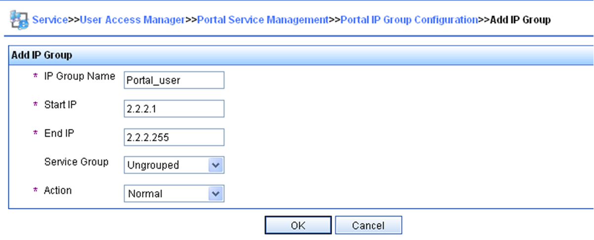
3. Add a portal device:
a. Select User Access Manager > Portal Service Management > Device from the navigation tree to open the portal device configuration page.
b. Click Add to open the page as shown in Figure 78.
c. Enter the device name NAS.
d. Enter the IP address of the interface through which the AP connects to the client.
e. Enter the key, which must be the same as that configured on the AP.
f. Set whether to enable IP address reallocation.
This example uses direct portal authentication, and therefore select No from the Reallocate IP list.
g. Select whether to support sever heartbeat and user heartbeat functions.
In this example, select Yes for both Support Server Heartbeat and Support User Heartbeat.
h. Click OK.
Figure 78 Adding a portal device
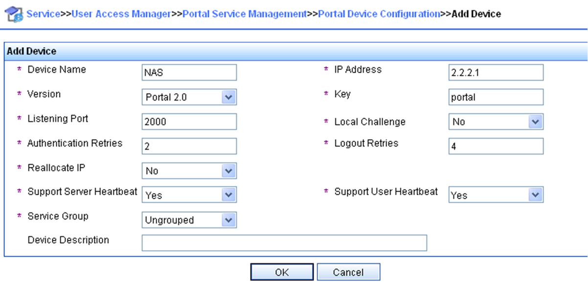
4. Associate the portal device with the IP address group:
a. As shown in Figure 79, click the icon in the Port Group Information Management column of device NAS to open the port group configuration page.
b. Click Add to open the page as shown in Figure 80.
c. Enter the port group name.
d. Select the configured IP address group.
The IP address used by the user to access the network must be within this IP address group.
e. Use the default settings for other parameters.
f. Click OK.
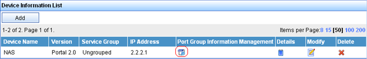

5. Select User Access Manager > Service Parameters > Validate System Configuration from the navigation tree to make the configurations take effect.
Configuring the AP
1. Assign IP addresses to interfaces and make sure the client, the AP, and the servers can reach each other. (Details not shown.)
2. Configure a RADIUS scheme:
# Create a RADIUS scheme named rs1 and enter its view.
<AP> system-view
[AP] radius scheme rs1
# Specify the primary authentication server and primary accounting server, and configure the keys for communication with the servers.
[AP-radius-rs1] primary authentication 192.168.0.112
[AP-radius-rs1] primary accounting 192.168.0.112
[AP-radius-rs1] key authentication simple radius
[AP-radius-rs1] key accounting simple radius
# Exclude the ISP domain name from the username sent to the RADIUS server.
[AP-radius-rs1] user-name-format without-domain
[AP-radius-rs1] quit
# Enable RADIUS session control.
[AP] radius session-control enable
3. Configure an authentication domain:
# Create an ISP domain named dm1 and enter its view.
[AP] domain dm1
# Configure AAA methods for the ISP domain.
[AP-isp-dm1] authentication portal radius-scheme rs1
[AP-isp-dm1] authorization portal radius-scheme rs1
[AP-isp-dm1] accounting portal radius-scheme rs1
[AP-isp-dm1] quit
# Configure domain dm1 as the default ISP domain. If a user enters the username without the ISP domain name at login, the authentication and accounting methods of the default domain are used for the user.
[AP] domain default enable dm1
4. Configure portal authentication:
# Configure a portal authentication server.
[AP] portal server newpt
[AP-portal-server-newpt] ip 192.168.0.111 key simple portal
[AP-portal-server-newpt] port 50100
# Configure reachability detection of the portal authentication server: set the server detection interval to 40 seconds, and send log messages upon reachability status changes.
[AP-portal-server-newpt] server-detect timeout 40 log
|
|
NOTE: The value of timeout must be greater than or equal to the portal server heartbeat interval. |
# Configure portal user synchronization with the portal authentication server, and set the synchronization detection interval to 600 seconds.
[AP-portal-server-newpt] user-sync timeout 600
[AP-portal-server-newpt] quit
|
|
NOTE: The value of timeout must be greater than or equal to the portal user heartbeat interval. |
# Configure a portal Web server.
[AP] portal web-server newpt
[AP-portal-websvr-newpt] url http://192.168.0.111:8080/portal
[AP-portal-websvr-newpt] quit
# Enable direct portal authentication on VLAN-interface 100.
[AP] interface vlan-interface 100
[AP–Vlan-interface100] portal enable method direct
# Enable portal fail-permit for the portal authentication server newpt.
[AP–Vlan-interface100] portal fail-permit server newpt
# Specify portal Web server newpt on VLAN-interface 100.
[AP–Vlan-interface100] portal apply web-server newpt
# Configure the BAS-IP as 2.2.2.1 for portal packets sent from VLAN-interface 100 to the portal authentication server.
[AP–Vlan-interface100] portal bas-ip 2.2.2.1
[AP–Vlan-interface100] quit
Verifying the configuration
# Display information about the portal authentication server.
[AP] display portal server newpt
Portal server: newpt
Type : IMC
IP : 192.168.0.111
Port : 50100
Server Detection : Timeout 40s Action: log
User synchronization : Timeout 600s
Status : Up
The Up status of the portal authentication server indicates that the portal authentication server is reachable. If the access device detects that the portal authentication server is unreachable, the Status field in the command output displays Down. The access device generates a server unreachable log "Portal server newpt turns down from up." and disables portal authentication on the access interface, so the client can access the external network without authentication.
Example: Configuring direct portal authentication with a preauthentication domain
Network configuration
As shown in Figure 81, the client accesses the WLAN through the AP and obtains a public IP address through DHCP. A portal server acts as both a portal authentication server and a portal Web server. A RADIUS server acts as the authentication/accounting server.
Configure direct portal authentication, so the client can access only subnet 192.168.0.0/24 before passing the authentication and can access other network resources after passing the authentication.

Configuring the RADIUS server
# Configure the RADIUS server correctly to provide authentication and accounting functions. (Details not shown.)
Configuring the AP
1. Assign IP addresses to interfaces and make sure the client, the AP, and the servers can reach each other. (Details not shown.)
2. Configure a preauthentication IP address pool:
# Configure DHCP address pool pre to assign IP addresses and other configuration parameters to clients on subnet 2.2.2.0/24.
<AP> system-view
[AP] dhcp server ip-pool pre
[AP-dhcp-pool-pre] gateway-list 2.2.2.1
[AP-dhcp-pool-pre] network 2.2.2.0 24
[AP-dhcp-pool-pre] quit
# Enable the DHCP server on VLAN-interface 100.
[AP] interface vlan-interface 100
[AP–Vlan-interface100] dhcp select server
[AP–Vlan-interface100] quit
3. Configure a preauthentication domain:
# Create an ISP domain named abc and enter its view.
[AP] domain abc
# Specify authorization ACL 3010 in the domain.
[AP-isp-abc] authorization-attribute acl 3010
[AP-isp-abc] quit
# Configure a rule to permit access to the subnet 192.168.0.0/24.
[AP-acl-ipv4-adv-3010] rule 1 permit ip destination 192.168.0.0 0.0.0.255
[AP-acl-ipv4-adv-3010] quit
# Configure preauthentication domain abc on VLAN-interface 100.
[AP] interface vlan-interface 100
[AP–Vlan-interface100] portal pre-auth domain abc
[AP–Vlan-interface100] quit
4. Configure portal authentication:
# Configure a portal authentication server.
[AP] portal server newpt
[AP-portal-server-newpt] ip 192.168.0.111 key simple portal
[AP-portal-server-newpt] port 50100
[AP-portal-server-newpt] quit
# Configure a portal Web server.
[AP] portal web-server newpt
[AP-portal-websvr-newpt] url http://192.168.0.111:8080/portal
[AP-portal-websvr-newpt] quit
# Enable direct portal authentication on VLAN-interface 100.
[AP] interface vlan-interface 100
[AP–Vlan-interface100] portal enable method direct
# Specify portal Web server newpt on VLAN-interface 100.
[AP–Vlan-interface100] portal apply web-server newpt
# Configure the BAS-IP as 2.2.2.1 for portal packets sent from VLAN-interface 100 to the portal authentication server.
[AP–Vlan-interface100] portal bas-ip 2.2.2.1
[AP–Vlan-interface100] quit
Verifying the configuration
# Verify the portal configuration by executing the display portal interface command. (Details not shown.)
# Display information about preauthentication portal users.
[AP] display portal user pre-auth interface vlan-interface 100
Total portal pre-auth users: 1
MAC IP VLAN Interface
0015-e9a6-7cfe 2.2.2.4 100 Vlan-interface100
State: Online
Authorization information:
DHCP IP pool: N/A
User profile: N/A
Session group profile: N/A
ACL number: 3010
Inbound CAR: N/A
Outbound CAR: N/A
Example: Configuring direct portal authentication using a local portal Web service
Network configuration
As shown in Figure 82, the client accesses the WLAN through the AP.
Configure direct portal authentication by using an HTTP-based portal Web service on the AP. The local portal Web server uses TCP port 2331 to listen to HTTP packets. Before a user passes portal authentication, the user can access only the local portal Web server. After passing portal authentication, the user can access other network resources.

Configuring the RADIUS server
# Configure the RADIUS server correctly to provide authentication and accounting functions. (Details not shown.)
Preparing the authentication page file
# Customize authentication pages, compress them to a file, and upload the file to the root directory of the storage medium of the AP.
Configuring the AP
1. Assign IP addresses to interfaces and make sure the client, the AP, and the servers can reach each other. (Details not shown.)
2. Configure a RADIUS scheme:
# Create a RADIUS scheme named rs1 and enter its view.
<AP> system-view
[AP] radius scheme rs1
# Specify the primary authentication server and primary accounting server, and configure the keys for communication with the servers.
[AP-radius-rs1] primary authentication 192.168.0.112
[AP-radius-rs1] primary accounting 192.168.0.112
[AP-radius-rs1] key authentication simple radius
[AP-radius-rs1] key accounting simple radius
# Exclude the ISP domain name from the username sent to the RADIUS server.
[AP-radius-rs1] user-name-format without-domain
[AP-radius-rs1] quit
# Enable RADIUS session control.
[AP] radius session-control enable
3. Configure an authentication domain:
# Create an ISP domain named dm1 and enter its view.
[AP] domain dm1
# Configure AAA methods for the ISP domain.
[AP-isp-dm1] authentication portal radius-scheme rs1
[AP-isp-dm1] authorization portal radius-scheme rs1
[AP-isp-dm1] accounting portal radius-scheme rs1
[AP-isp-dm1] quit
# Configure domain dm1 as the default ISP domain. If a user enters the username without the ISP domain name at login, the authentication and accounting methods of the default domain are used for the user.
[AP] domain default enable dm1
4. Configure portal authentication:
# Configure a portal Web server.
[AP] portal web-server newpt
[AP-portal-websvr-newpt] url http://2.2.2.1:2331/portal
[AP-portal-websvr-newpt] quit
# Enable direct portal authentication on VLAN-interface 100.
[AP] interface vlan-interface 100
[AP–Vlan-interface100] portal enable method direct
# Specify portal Web server newpt on VLAN-interface 100.
[AP–Vlan-interface100] portal apply web-server newpt
[AP–Vlan-interface100] quit
# Create an HTTP-based local portal Web service and enter its view.
[AP] portal local-web-server http
# Specify file abc.zip as the default authentication page file for the local portal Web service. (Make sure the file exist under the root directory of the AP.)
[AP–portal-local-websvr-http] default-logon-page abc.zip
# Set the HTTP listening port number to 2331 for the local portal Web service.
[AP–portal-local-websvr-http] tcp-port 2331
[AP–portal-local-websvr-http] quit
Verifying the configuration
# Verify that the portal configuration has taken effect.
[AP] display portal interface vlan-interface 100
Portal information of Vlan-interface 100
Authorization :Strict checking
ACL :Disabled
User profile :Disabled
Dual stack : Disabled
Dual traffic-separate: Disabled
IPv4:
Portal status: Enabled
Portal authentication type: Direct
Portal Web server: newpt(active)
Secondary portal Web server: Not configured
Portal mac-trigger-server: Not configured
Authentication domain: Not configured
Pre-auth domain: Not configured
Extend-auth domain: Not configured
User-dhcp-only: Disabled
Pre-auth IP pool: Not configured
Max portal users: Not configured
Bas-ip: Not configured
User detection: Not configured
Portal temp-pass: Disabled
Action for server detection:
Server type Server name Action
-- -- --
Destination authenticate subnet:
IP address Mask
IPv6:
Portal status: Disabled
Portal authentication type: Disabled
Portal Web server: Not configured
Secondary portal Web server: Not configured
Portal mac-trigger-server: Not configured
Authentication domain: Not configured
Pre-auth domain: Not configured
Extend-auth domain: Not configured
User-dhcp-only: Disabled
Pre-auth IP pool: Not configured
Max portal users: Not configured
Bas-ipv6: Not configured
User detection: Not configured
Portal temp-pass: Disabled
Action for server detection:
Server type Server name Action
-- -- --
Destination authenticate subnet:
IP address Prefix length
A user can perform portal authentication through a Web page. Before passing the authentication, the user can access only the authentication page http://2.2.2.1:2331/portal and all Web requests will be redirected to the authentication page. After passing the authentication, the user can access other network resources.
# After the user passes authentication, display information about the portal user.
[AP] display portal user interface vlan-interface 100
Total portal users: 1
Username: abc
Portal server: newpt
State: Online
MAC IP VLAN Interface
0015-e9a6-7cfe 2.2.2.2 100 Vlan-interface100
Authorization information:
DHCP IP pool: N/A
User profile: N/A
Session group profile: N/A
ACL: N/A
CAR: N/A
Inbound CAR: N/A
Outbound CAR: N/A
Troubleshooting portal
No portal authentication page is pushed for users
Symptom
When a user is redirected to the IMC portal authentication server, no portal authentication page or error message is prompted for the user. The login page is blank.
Analysis
The key configured on the portal access device and that configured on the portal authentication server are inconsistent. As a result, packet verification fails, and the portal authentication server refuses to push the authentication page.
Solution
Use the display portal server command on the access device to check whether a key is configured for the portal authentication server.
· If no key is configured, configure the right key.
· If a key is configured, use the ip or ipv6 command in the portal authentication server view to correct the key, or correct the key configured for the access device on the portal authentication server.
Cannot log out portal users on the access device
Symptom
You cannot use the portal delete-user command on the access device to log out a portal user, but the portal user can log out by clicking the Disconnect button on the portal authentication client.
Analysis
When you execute the portal delete-user command on the access device to log out a user, the access device sends an unsolicited logout notification message to the portal authentication server. The destination port number in the logout notification is the listening port number of the portal authentication server configured on the access device. If this listening port number is not the actual listening port number configured on the server, the server cannot receive the notification. As a result, the server does not log out the user.
When a user uses the Disconnect button on the authentication client to log out, the portal authentication server sends an unsolicited logout request message to the access device. The access device uses the source port in the logout request as the destination port in the logout ACK message. As a result, the portal authentication server can definitely receive the logout ACK message and log out the user.
Solution
1. Use the display portal server command to display the listening port of the portal authentication server configured on the access device.
2. Use the portal server command in system view to change the listening port number to the actual listening port of the portal authentication server.
Cannot log out portal users on the RADIUS server
Symptom
The access device uses the H3C IMC server as the RADIUS server to perform identity authentication for portal users. You cannot log out the portal users on the RADIUS server.
Analysis
The H3C IMC server uses session control packets to send disconnection requests to the access device. On the access device, the listening UDP port for session control packets is disabled by default. Therefore, the access device cannot receive the portal user logout requests from the RADIUS server.
Solution
On the access device, execute the radius session-control enable command in system view to enable the RADIUS session control function.
Users logged out by the access device still exist on the portal authentication server
Symptom
After you log out a portal user on the access device, the user still exists on the portal authentication server.
Analysis
When you execute the portal delete-user command on the access device to log out a user, the access device sends an unsolicited logout notification to the portal authentication server. If the BAS-IP or BAS-IPv6 address carried in the logout notification is different from the portal device IP address specified on the portal authentication server, the portal authentication server discards the logout notification. When sending of the logout notifications times out, the access device logs out the user. However, the portal authentication server does not receive the logout notification successfully, and therefore it regards the user is still online.
Solution
Configure the BAS-IP or BAS-IPv6 attribute on the interface enabled with portal authentication. Make sure the attribute value is the same as the portal device IP address specified on the portal authentication server.
Re-DHCP portal authenticated users cannot log in successfully
Symptom
The device performs re-DHCP portal authentication for users. A user enters the correct username and password, and the client successfully obtains the private and public IP addresses. However, the authentication result for the user is failure.
Analysis
When the access device detects that the client IP address is changed, it sends an unsolicited portal packet to notify of the IP change to the portal authentication server. The portal authentication server notifies of the authentication success only after it receives the IP change notification from both the access device and the client.
If the BAS-IP or BAS-IPv6 address carried in the portal notification packet is different from the portal device IP address specified on the portal authentication server, the portal authentication server discards the portal notification packet. As a result, the portal authentication server considers that the user has failed the authentication.
Solution
Configure the BAS-IP or BAS-IPv6 attribute on the interface enabled with portal authentication. Make sure the attribute value is the same as the portal device IP address specified on the portal authentication server.