- Table of Contents
- Related Documents
-
| Title | Size | Download |
|---|---|---|
| 01-Text | 1.18 MB |
Contents
About the SeerEngine-DC controller
Deployment procedure at a glance
Registering and installing licenses
Registering and installing licenses for SNA Center
Registering and installing licenses for the controller
Installing the activation file on the license server
About the SeerEngine-DC controller
SeerEngine-DC is a data center controller that runs on SeerNetwork Architecture (SNA) Center. SNA Center is the core component of a digital network to provide unified network management, control, intelligent analysis, and service orchestration.
Similar to a network operating system, the SeerEngine-DC controller allows users to develop and run SDN applications. It can control various resources on an OpenFlow network and provide interfaces for applications to enable specific network forwarding.
The controller has the following features:
· It supports OpenFlow 1.3 and provides built-in services and a device driver framework.
· It is a distributed platform with high availability and scalability.
· It provides extensible REST APIs, GUI, and H3C IMC management interface.
Preparing for installation
Server requirements
Hardware requirements
Table 1 describes the hardware requirements for installing the controller on SNA Center.
Table 1 Hardware requirements (recommended configuration)
|
Item |
Requirements |
|
CPU |
x86-64 (Intel 64/AMD 64) 20 cores 2.2 GHz or above |
|
Memory size |
128 GB or above |
|
Drive |
· RAID controller: 1G cache memory, support for power fail protection · One of the drive configuration options: ¡ One 1 TB or above SAS SSD or NVMe SSD ¡ Two 1 TB or above 7.2K RPM SATA/SAS HDDs, RAID 1, 5, or 10 setup with the drive space not less than 1 TB |
|
NIC |
vBGP not configured: · Non-bonding mode: 1 × 10 Gbps or above Ethernet port · Bonding mode (recommended mode: mode 2 or mode 4): 2 × 10 Gbps Linux bonding interfaces vBGP configured: · Non-bonding mode: 2 × 10 Gbps or above Ethernet ports · Bonding mode (recommended mode: mode 4): 4 × 10 Gbps Linux bonding interfaces |
Table 2 Hardware requirements (standard configuration)
|
Item |
Requirements |
|
CPU |
x86-64 (Intel 64/AMD 64) 16 cores 2.0 GHz or above |
|
Memory size |
64 GB or above |
|
Drive |
· RAID controller: 1G cache memory, support for power fail protection · One of the drive configuration options: ¡ One 1 TB or above SAS SSD or NVMe SSD ¡ Two 1 TB or above 7.2K RPM SATA/SAS HDDs, RAID 1, 5, or 10 setup with the drive space not less than 1 TB |
|
NIC |
vBGP not configured: · Non-bonding mode: 1 × 10 Gbps or above Ethernet port · Bonding mode (recommended mode: mode 2 or mode 4): 2 × 10 Gbps Linux bonding interfaces vBGP configured: · Non-bonding mode: 2 × 10 Gbps or above Ethernet ports · Bonding mode (recommended mode: mode 4): 4 × 10 Gbps Linux bonding interfaces |
|
|
IMPORTANT: · To avoid unrecoverable system failures caused by unexpected power failures, use a RAID controller that supports power fail protection for the server and make sure the supercapacitor is in place. · The server must support the CentOS 7.5 or later operating system. |
Software requirements
SNA Center must be deployed on the H3Linux operating system. This operating system is contained in the SNA_CENTER-PACKAGE-version.iso image with the installation packages of SNA Installer, SNA Center, and license server. You can install the operating system from this image file.
Client requirements
You can access SNA Center from a Web browser without installing any client. As a best practice, use a Google Chrome 60 or later Web browser.
Pre-installation checklist
Table 3 Pre-installation checklist
|
Item |
Requirements |
|
|
Server |
Hardware |
· The CPUs, memory, disks, and NICs meet the requirements. · The server supports the CentOS 7.5 or later operating system. |
|
Software |
The system time settings are configured correctly. As a best practice, configure NTP for time synchronization and make sure the devices synchronize to the same clock source. |
|
|
Client |
You can access SNA Center from a Web browser without installing any client. As a best practice, use a Google Chrome 60 or later Web browser. |
|
Deployment procedure at a glance
Use the following procedure to deploy the controller:
1. Prepare for installation.
Prepare three physical servers. Make sure the physical servers meet the hardware and software requirements as described in "Server requirements."
2. Deploy the H3Linux operating system and SNA Installer.
For the deployment procedure, see H3C SNA Center Installation and Component Deployment Guide.
3. Install SNA Center.
For the SNA Center installation procedure, see H3C SNA Center Installation and Component Deployment Guide.
4. Deploy the controller.
Installing SNA Center
The controller must be deployed on SNA Center. To deploy the controller, first install SNA Center. For the SNA Center installation procedure, see H3C SNA Center Installation and Component Deployment Guide.
Deploying the controller
|
|
IMPORTANT: The controller runs on SNA Center. You can deploy, upgrade, and uninstall it only on SNA Center. |
Preparing for deployment
Enabling NICs
The procedure is the same for all NICs. The following procedure enables NIC ens34.
To enable a NIC:
1. Access the server that hosts SNA Center.
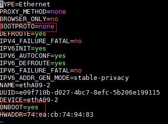
2. Access the NIC configuration file.
[root@sna001 /]# vi /etc/sysconfig/network-scripts/ifcfg-ens34
3. Set the BOOTPROTO field to none to not specify a boot-up protocol and set the ONBOOT field to yes to activate the NIC at system startup.
Figure 1 Modifying the configuration file of a NIC
4. Execute the ifdown and ifup commands in sequence to reboot the NIC.
[root@sna001 /]# ifdown ens34
[root@sna001 /]# ifup ens34
5. Execute the ifconfig command to verify that the NIC is in up state.
Planning the network
Network planning
You are required to plan for the Calico network, MACVLAN network, and OVS-DPDK network.
The Calico network is an internal network used for container interactions. The network segment of the Calico network is the IP address pool set for containers when the SNA Installer cluster is deployed. The default network segment is 177.177.0.0. You do not need to configure an address pool for the Calico network when installing and deploying the controller. The Calico network and MACVLAN network can use the same NIC.
Before deploying the controller, plan the address pools for the MACVLAN and OVS-DPDK networks in advance. Both networks are used as management networks. The MACVLAN network is the management network of the SeerEngine-DC and vDHCP components. The OVS-DPDK network is the management network of the vBGP component.
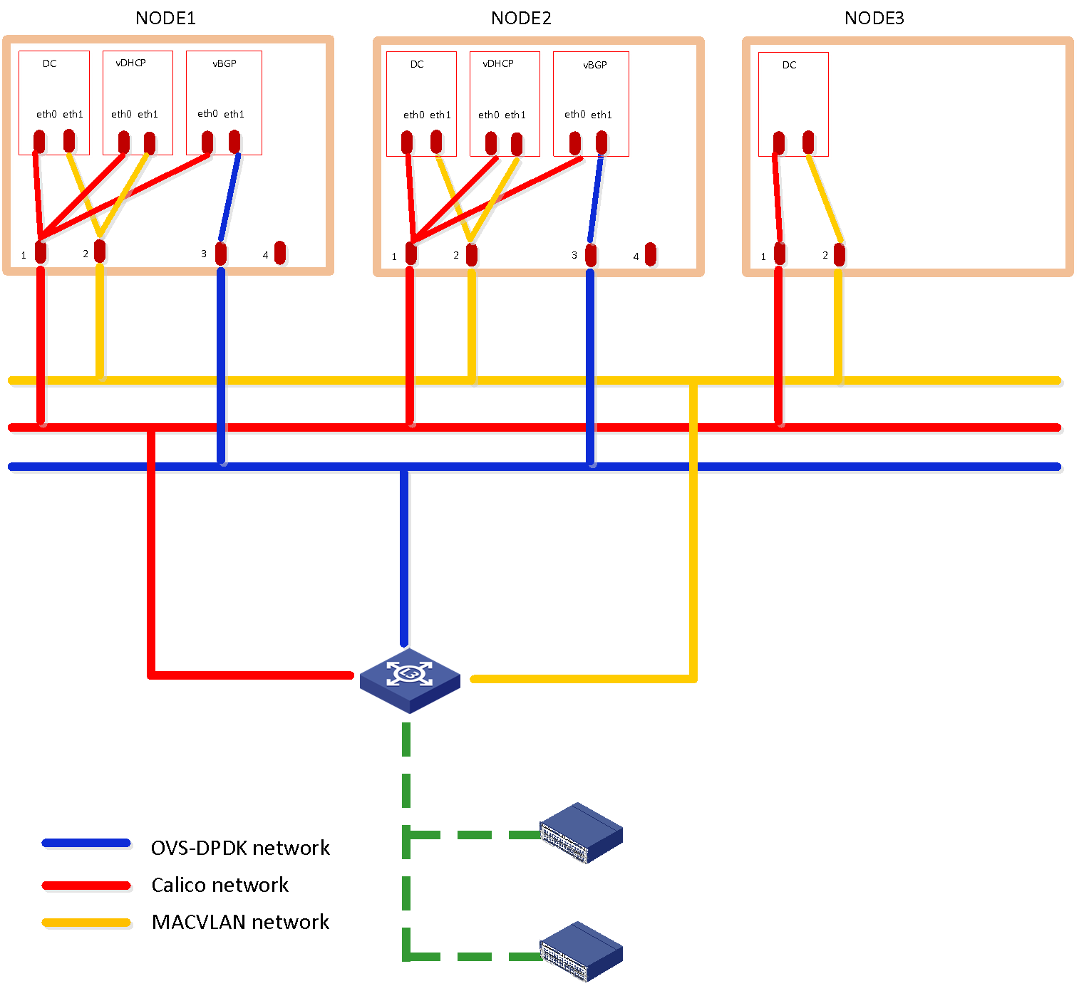
vBGP is an optional component. To not deploy vBGP, configure only the MACVLAN network as shown in Figure 2. To deploy vBGP, configure both MACVLAN and OVS-DPDK networks as shown in Figure 3.
Figure 2 Data center scenario (to not deploy vBGP)
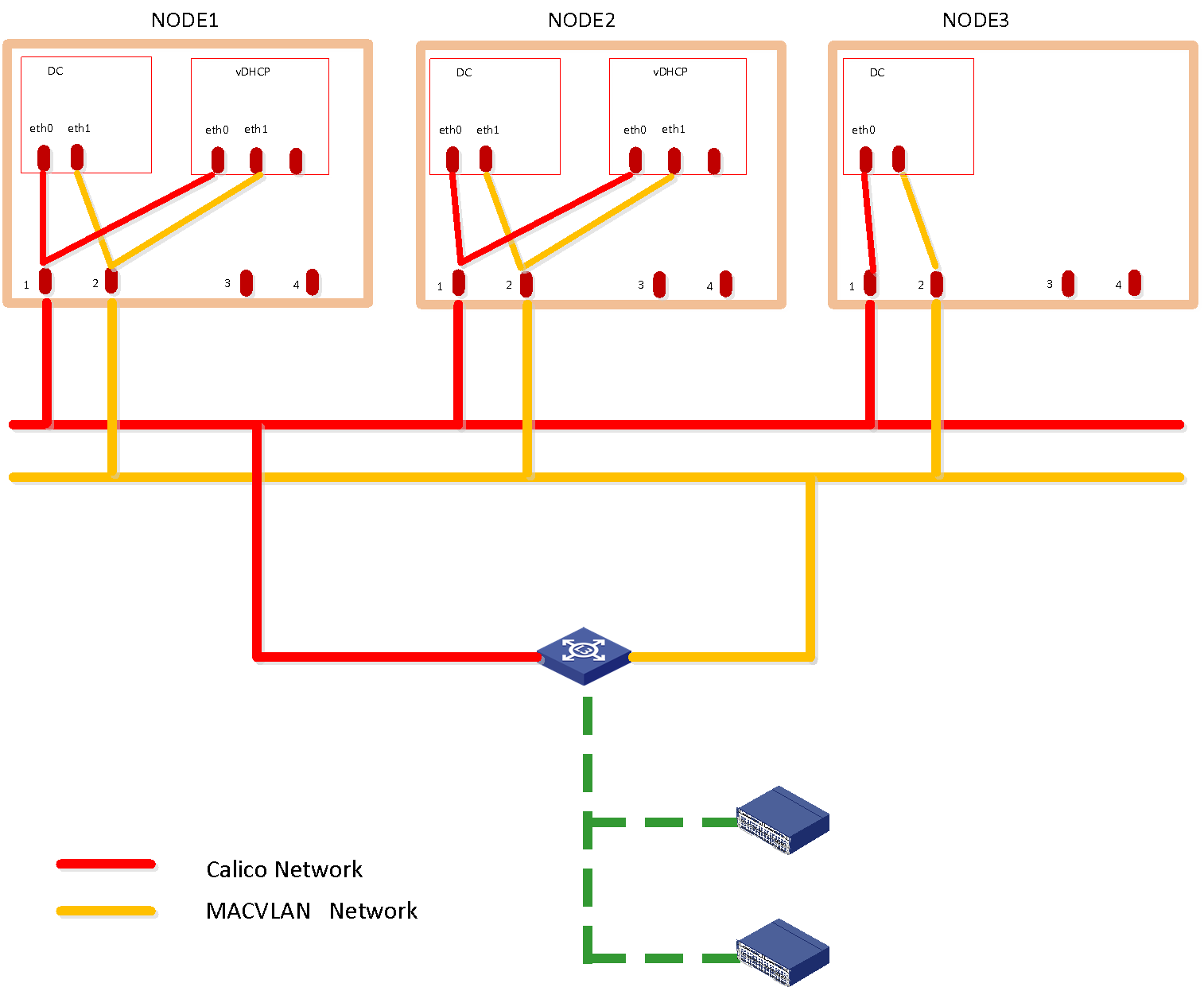
Figure 3 Data center scenario (to deploy vBGP)
IP address planning
To calculate the IP addresses required for a MACVLAN or OVS-DPDK subnet.
1. Use Table 4 as a best practice to calculate the number of IP addresses required for each component team.
Table 4 Number of IP addresses required for each component team
|
Component |
Maximum team members |
Default team members |
Number of IP addresses |
|
SeerEngine-DC |
32 |
3 |
Number of team members + 1 (team IP) |
|
vDHCP |
2 |
2 |
Number of team members + 1 (team IP) |
|
vBGP |
2 |
2 |
Number of team members + 1 (team IP) |
2. Calculate the number of IP addresses required for the subnet.
For example, if the SeerEngine-DC controller team has 3 members, the vDHCP team has 2 members, and the vBGP team has 2 members, the number of required IP addresses is as follows:
¡ MACVLAN subnet: (1*3+1)+ (1*2+1) = 7.
¡ OVS-DPDK subnet: (1*2+1) = 3.
Table 5 shows an example for IP address planning.
|
Item |
IP addresses |
|
MACVLAN subnet |
10.0.234.0/24 (gateway 10.0.234.254) |
|
MACVLAN network address pool |
10.0.234.6 to 10.0.234.38 |
|
OVS-DPDK subnet |
11.0.234.0/24 (gateway 11.0.234.254) |
|
OVS-DPDK network address pool |
11.0.234.1 to 11.0.234.32 |
Deploying the controller
1. Log in to SNA Center. Click System > Settings.
2. On the top navigation bar, click Components, and then select Components from the navigation pane.
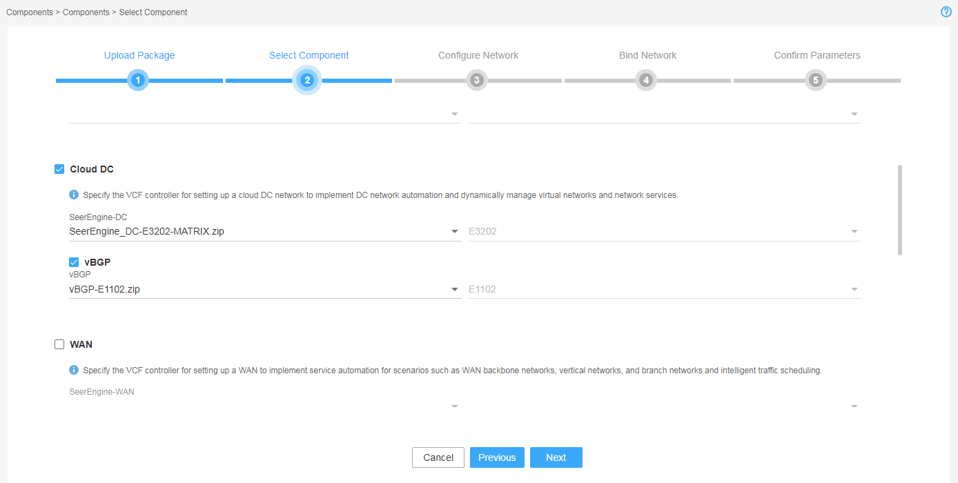
3. Click Upload to upload the installation package and then click Next.
4. Select Cloud DC and then click Next. If you are to deploy vBGP, select also vBGP.
In this example, vBGP is selected.
Figure 4 Selecting components
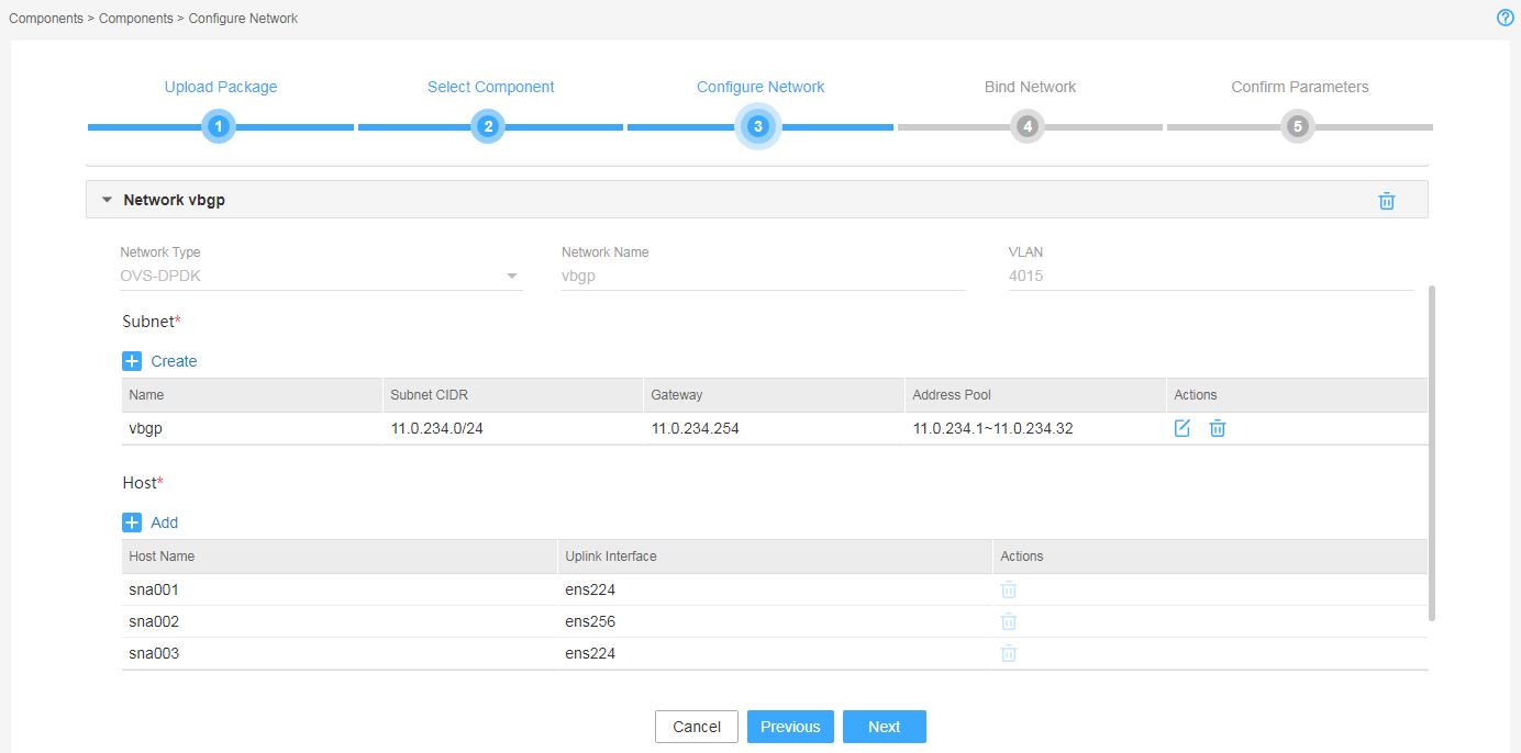
5. Configure the MACVLAN and OVS-DPDK networks and add the uplink interfaces according to the network plan in "Planning the network."
If vBGP is not to be deployed, you only need to configure the MACVLAN network.
Figure 5 Configuring the MACVLAN network
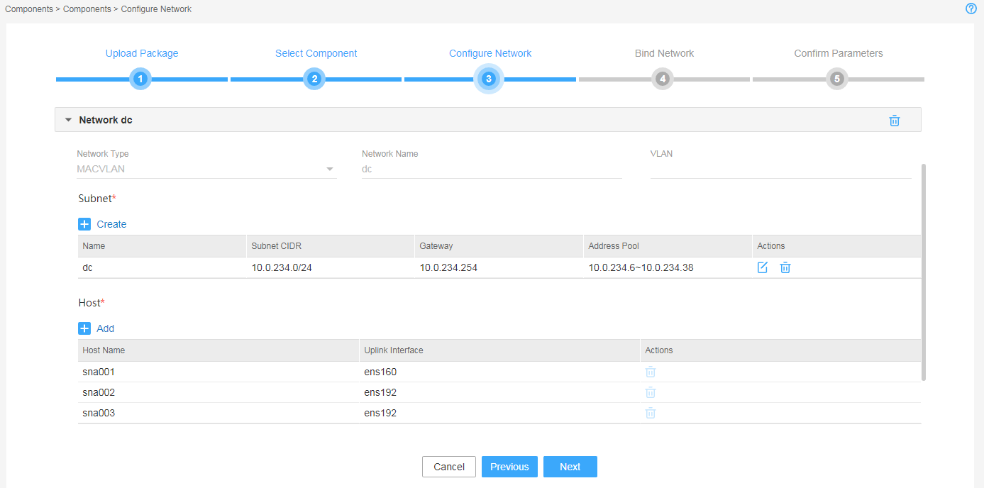
Figure 6 Configuring the OVS-DPDK network
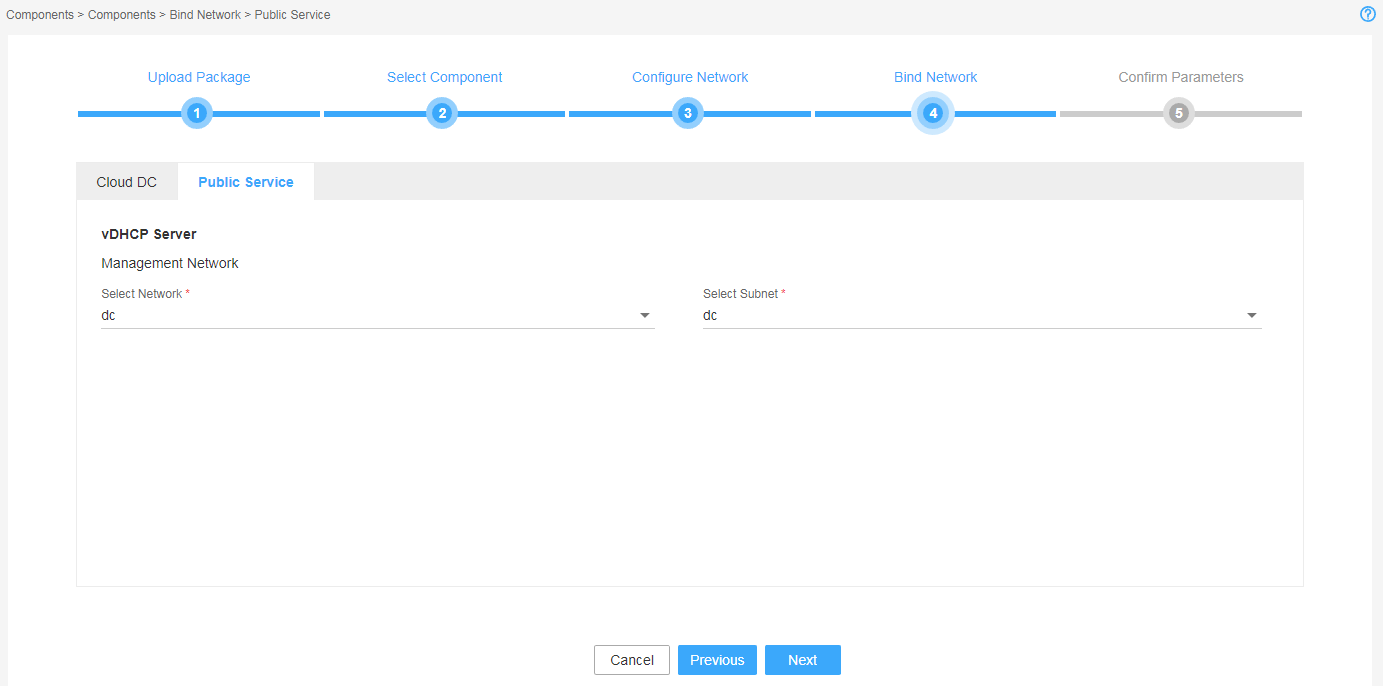
6. Bind networks to the components, assign IP address to the components, and then click Next.
Figure 7 Binding networks to components (1)
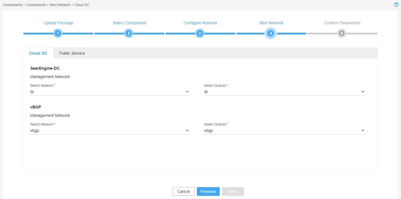
Figure 8 Binding networks to components (2)
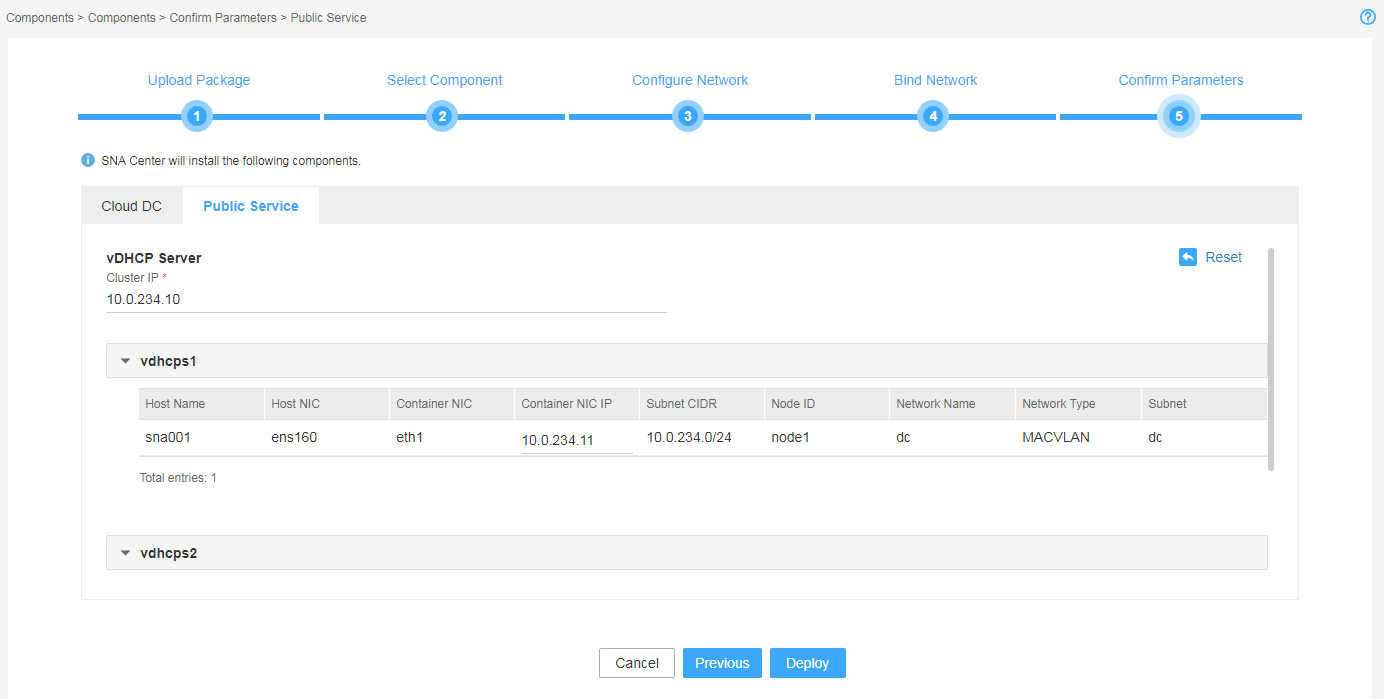
7. Verify the configuration and then click Deploy.
A component automatically obtains an IP address from the IP address pool of the subnet bound to it. To modify the IP address, click Modify and then specify another IP address for the component. The IP address specified must be in the IP address range of the subnet bound to the component.
Figure 9 Verifying the configuration (1)
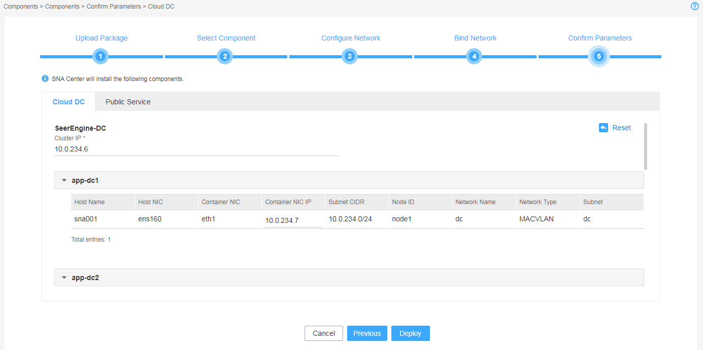
Figure 10 Verifying the configuration (2)
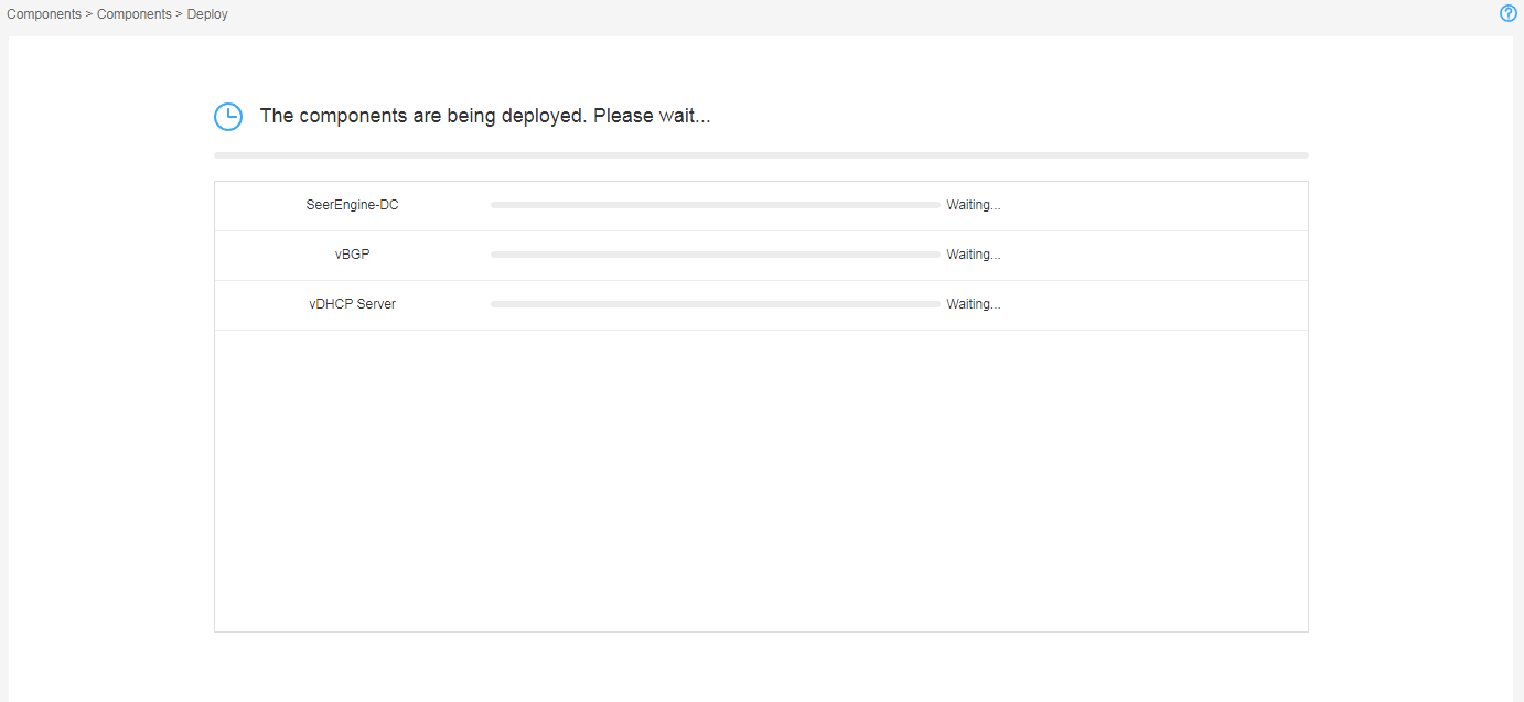
8. Click Deploy.
Figure 11 Components in deployment
Accessing the controller
The controller runs on SNA Center. To access the controller, first log in to SNA Center.
To log in to the controller:
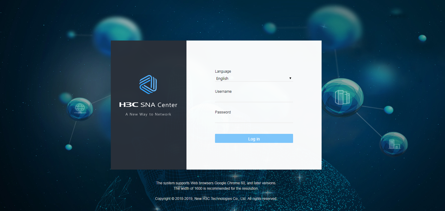
1. Enter the address for accessing SNA Center in the address bar and then press Enter.
By default, the login address is https://sna_center_ip_address:10443/portal. However, if you have specified the HTTP login protocol during the SNA Center deployment process, the login address is http://sna_center_ip_address:10080/portal.
¡ sna_center_ip_address represents the northbound virtual IP address of the SNA Installer cluster.
¡ 10443 and 10080 are port numbers.
2. Enter the username and password, and then click Log in.
The default username is admin and the default password is admin@123.
Figure 12 SNA Center login page
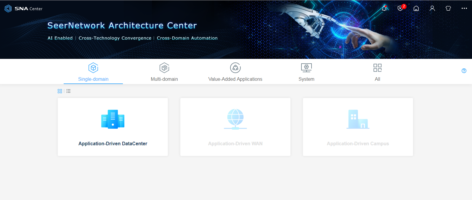
3. On the SNA Center home page, click Application-Driven DataCenter.
Figure 13 SNA Center home page
Registering and installing licenses
Registering and installing licenses for SNA Center
For the SNA Center license registration and installation procedure, see H3C SNA Center Installation and Components Deployment Guide.
Registering and installing licenses for the controller
After you install the controller, you can use its complete features and functions for a 180-day trial period. After the trial period expires, you must get the controller licensed.
Installing the activation file on the license server
For the activation file request and installation procedure, see H3C Software Products Remote Licensing Guide.
Obtaining licenses
1. Log in to SNA Center and click Application-Driven DataCenter.
2. Click Settings in the System area. From the navigation pane, select License.
3. Configure the parameters for the license server as described in Table 11.
Table 6 License server parameters
|
Item |
Description |
|
IP address |
Specify the IP address configured on the license server used for internal communication in the cluster. |
|
Port number |
Specify the service port number of the license server. The default value is 5555. |
|
Username |
Specify the client username configured on the license server. |
|
Password |
Specify the client password configured on the license server. |
4. Click Connect to connect the controller to the license server.
The controller will automatically obtain licensing information after connecting to the license server.
Backing up and restoring the controller configuration
You can back up and restore the controller configuration on SNA Center. For the procedures, see H3C SNA Center Installation and Component Deployment Guide.
Upgrading the controller
|
|
CAUTION: The upgrade might cause service interruption. Be cautious when you perform this operation. |
The controller can be upgraded on SNA Center with the configuration retained.
To upgrade the controller:
1. Log in to SNA Center. Click System > Settings.
2. On the top navigation bar, click Components, and then select Components from the navigation pane.
3. Click the right chevron button ![]() for the controller to expand controller information, and then click the upgrade icon
for the controller to expand controller information, and then click the upgrade icon ![]() .
.
4. Upload the installation package.
5. Select the installation package and then click Deploy.
6. If the upgrade fails, click Roll Back to roll back to the previous version.
Uninstalling the controller
1. Log in to SNA Center. Click System > Settings.
2. On the top navigation bar, click Components, and then select Components from the navigation pane.
3. Select the controller and then click ![]() .
.