- Table of Contents
- Related Documents
-
| Title | Size | Download |
|---|---|---|
| 02-Hardware Information and Specifications | 431.93 KB |
1 Product models and technical specifications
Product models
This document provides an installation guide for the following switch series:
· S6812 switch series
· S6813 switch series
Table1-1 describes the switch models that each switch series includes.
Table1-1 Switch series and models
|
Switch series |
Model |
Product code (PID) |
|
S6812 switch series |
S6812-24X6C |
LS-6812-24X6C |
|
S6812-48X6C |
LS-6812-48X6C |
|
|
S6813 switch series |
S6813-24X6C |
LS-6813-24X6C |
|
S6813-48X6C |
LS-6813-48X6C |
Technical specifications
Table1-2 Technical specifications
|
Item |
S6812-24X6C |
S6812-48X6C |
S6813-24X6C |
S6813-48X6C |
|
Dimensions (H × W × D) |
44 × 440 × 360 mm (1.72 × 17.32 × 14.17 in) |
|||
|
Weight |
≤ 5.5 kg (12.13 lb) |
≤ 6 kg (13.22 lb) |
≤ 6 kg (13.22 lb) |
≤ 6.5 kg (14.33 lb) |
|
Console port |
1 × serial console port |
|||
|
USB port |
1 |
1 |
1 |
1 |
|
Management Ethernet port |
1 |
1 |
1 |
1 |
|
SFP+ port |
24 |
48 |
24 |
48 |
|
QSFP28 port |
6 |
6 |
6 |
6 |
|
Power module slot |
2, on the rear panel |
|||
|
Fan tray slot |
3, on the rear panel |
|||
|
Input voltage |
AC input for the PSR180-12A-F or PSR180-12A-B power module: · Rated voltage: 100 VAC to 240 VAC @ 50 or 60 Hz · Max voltage: 90 VAC to 264 VAC @ 47 to 63 Hz |
|||
|
Minimum power consumption |
· Single AC input: 29 W · Dual AC inputs: 35 W |
· Single AC input: 29 W · Dual AC inputs: 36 W |
· Single AC input: 38 W · Dual AC inputs: 46 W |
· Single AC input: 36 W · Dual AC inputs: 44 W |
|
Maximum power consumption |
· Single AC input: 131 W · Dual AC inputs: 134 W |
· Single AC input: 162 W · Dual AC inputs: 163 W |
· Single AC input: 143 W · Dual AC inputs: 145 W |
· Single AC input: 176 W · Dual AC inputs: 177 W |
|
Melting current of power supply fuse |
6.3 A @ 250 V |
6.3 A @ 250 V |
6.3 A @ 250 V |
6.3 A @ 250 V |
|
Operating temperature |
–5°C to +45°C (23°F to 113°F) |
|||
|
Operating humidity |
5% RH to 95% RH, noncondensing |
|||
|
Safety regulation compliance |
UL 62368-1/EN 62368-1/IEC 62368-1/UL 60950-1/EN 60950-1/IEC 60950-1/GB4943.1 |
|||
2 Chassis views
S6812-24X6C
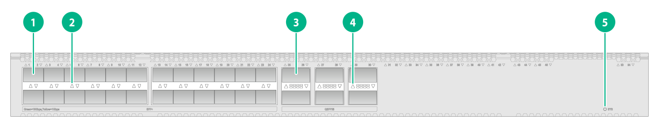
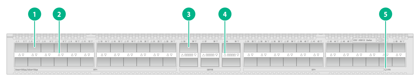
Figure2-1 Front panel
|
(1) SFP+ port |
(2) SFP+ port LED |
|
(3) QSFP28 port |
(4) QSFP28 port LED |
|
(5) System status LED (SYS) |
|

|
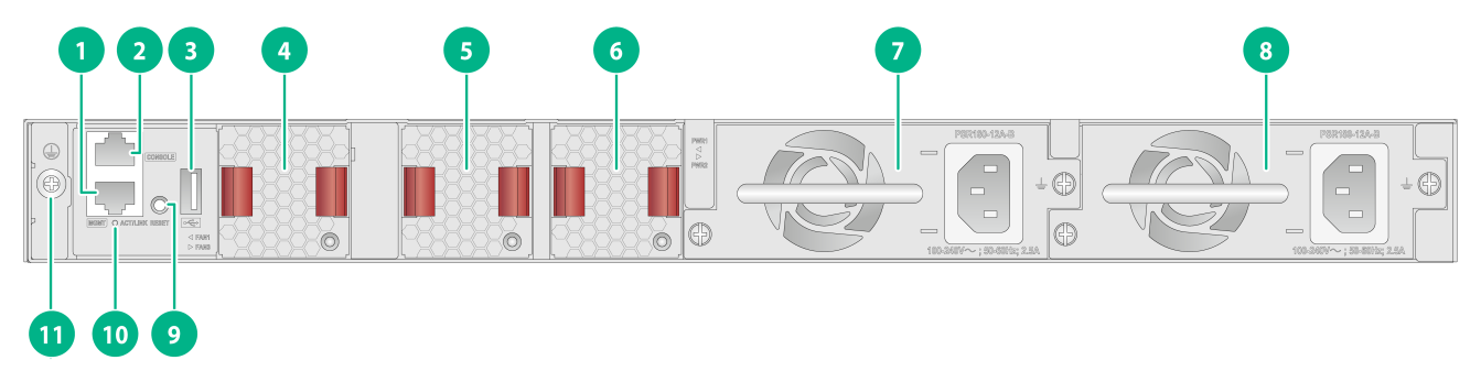
(1) Management Ethernet port |
(2) Console port (CONSOLE) |
|
(3) USB port |
(4) Fan tray 1 |
|
(5) Fan tray 2 |
(6) Fan tray 3 |
|
(7) Power module 1 |
(8) Power module 2 |
|
(9) RESET button |
(10) Management Ethernet port LED (ACT/LINK) |
|
(11) Grounding screw |
|
The S6812-24X6C switch comes with power module slot 1 empty and power module slot 2 installed with a filler panel. You can install one or two power modules for the switch as required. In Figure2-2, two PSR180-12A-B AC power modules are installed in the power module slots.
The S6812-24X6C switch comes with the three fan tray slots empty. You must install three fan trays of the same model for the switch. In Figure2-2, three LSPM1FANSB-SN fan trays are installed in the fan tray slots.
The S6812-24X6C switch provides a reset button on the rear panel for you to reset the switch.
S6812-48X6C
Figure2-3 Front panel

|
(1) SFP+ port |
(2) SFP+ port LED |
|
(3) QSFP28 port |
(4) QSFP28 port LED |
|
(5) System status LED (SYS) |
|

|
(1) Management Ethernet port |
(2) Console port (CONSOLE) |
|
(3) USB port |
(4) Fan tray 1 |
|
(5) Fan tray 2 |
(6) Fan tray 3 |
|
(7) Power module 1 |
(8) Power module 2 |
|
(9) RESET button |
(10) Management Ethernet port LED (ACT/LINK) |
|
(11) Grounding screw |
|
The S6812-48X6C switch comes with power module slot 1 empty and power module slot 2 installed with a filler panel. You can install one or two power modules for the switch as required. In Figure2-4, two PSR180-12A-B AC power modules are installed in the power module slots.
The S6812-48X6C switch comes with the three fan tray slots empty. You must install three fan trays of the same model for the switch. In Figure2-4, three LSPM1FANSB-SN fan trays are installed in the fan tray slots.
The S6812-48X6C switch provides a reset button on the rear panel for you to reset the switch.
S6813-24X6C
Figure2-5 Front panel

|
(1) SFP+ port |
(2) SFP+ port LED |
|
(3) QSFP28 port |
(4) QSFP28 port LED |
|
(5) System status LED (SYS) |
|
|
(1) Management Ethernet port |
(2) Console port (CONSOLE) |
|
(3) USB port |
(4) Fan tray 1 |
|
(5) Fan tray 2 |
(6) Fan tray 3 |
|
(7) Power module 1 |
(8) Power module 2 |
|
(9) RESET button |
(10) Management Ethernet port LED (ACT/LINK) |
|
(11) Grounding screw |
|
The S6813-24X6C switch comes with power module slot 1 empty and power module slot 2 installed with a filler panel. You can install one or two power modules for the switch as required. In Figure2-6, two PSR180-12A-B AC power modules are installed in the power module slots.
The S6813-24X6C switch comes with the three fan tray slots empty. You must install three fan trays of the same model for the switch. In Figure2-6, three LSPM1FANSB-SN fan trays are installed in the fan tray slots.
The S6813-24X6C switch provides a reset button on the rear panel for you to reset the switch.
S6813-48X6C
Figure2-7 Front panel
|
(1) SFP+ port |
(2) SFP+ port LED |
|
(3) QSFP28 port |
(4) QSFP28 port LED |
|
(5) System status LED (SYS) |
|

|
(1) Management Ethernet port |
(2) Console port (CONSOLE) |
|
(3) USB port |
(4) Fan tray 1 |
|
(5) Fan tray 2 |
(6) Fan tray 3 |
|
(7) Power module 1 |
(8) Power module 2 |
|
(9) RESET button |
(10) Management Ethernet port LED (ACT/LINK) |
|
(11) Grounding screw |
|
The S6813-48X6C switch comes with power module slot 1 empty and power module slot 2 installed with a filler panel. You can install one or two power modules for the switch as required. In Figure2-8, two PSR180-12A-B AC power modules are installed in the power module slots.
The S6813-48X6C switch comes with the three fan tray slots empty. You must install three fan trays of the same model for the switch. In Figure2-8, three LSPM1FANSB-SN fan trays are installed in the fan tray slots.
The S6813-48X6C switch provides a reset button on the rear panel for you to reset the switch.
3 FRUs and compatibility matrixes
The S6812 & S6813 switch series uses modular design and supports FRUs.
Table3-1 FRUs and compatibility matrixes
|
FRUs |
S6812-24X6C |
S6812-48X6C |
S6813-24X6C |
S6813-48X6C |
|
Removable power modules |
||||
|
PSR180-12A-F |
Supported |
Supported |
Supported |
Supported |
|
PSR180-12A-B |
Supported |
Supported |
Supported |
Supported |
|
Removable fan trays |
||||
|
LSPM1FANSA-SN |
Supported |
Supported |
Supported |
Supported |
|
LSPM1FANSB-SN |
Supported |
Supported |
Supported |
Supported |
The power modules and fan trays support asset management. You can use the display device manuinfo command to view the name, sequence number, and vendor of the power modules and fan trays you have installed on the device.
Removable power modules
The S6812 & S6813 switch series provides power module slots and uses removable power modules. Select power modules for the switches as required.
Table3-2 Removable power modules
|
Power module |
Specifications |
Reference |
|
PSR180-12A-F |
· Rated input voltage range: 100 VAC to 240 VAC @ 50 Hz or 60 Hz · Max input voltage range: 90 VAC to 264 VAC @ 47 Hz to 63 Hz · Max output power: 180 W · Melting current of power supply fuse: 6.3 A/250 V |
H3C PSR180-12A & PSR180-12D Power Supply Series User Manual |
|
PSR180-12A-B |
· Rated input voltage range: 100 VAC to 240 VAC @ 50 Hz or 60 Hz · Max input voltage range: 90 VAC to 264 VAC @ 47 Hz to 63 Hz · Max output power: 180 W · Melting current of power supply fuse: 6.3 A/250 V |
Removable fan trays
The S6812 & S6813 switch series supports the LSPM1FANSA-SN and LSPM1FANSB-SN fan trays.
Table3-3 Removable fan trays
|
Item |
Specifications |
|
LSPM1FANSA-SN fan tray |
|
|
Dimensions (H × W × D) |
40 × 40.6 × 105 mm (1.57 × 1.60 × 4.13 in) |
|
Fan speed |
20000 R.P.M |
|
Max airflow |
20 CFM |
|
Airflow direction |
From the power module side to the port side |
|
Input voltage |
12 V |
|
Maximum power consumption |
9.8 W |
|
Reference |
H3C LSPM1FANSA-SN & LSPM1FANSB-SN Fan Trays User Guide |
|
LSPM1FANSB-SN fan tray |
|
|
Dimensions (H × W × D) |
40 × 40.6 × 105 mm (1.57 × 1.60 × 4.13 in) |
|
Fan speed |
20000 R.P.M |
|
Max airflow |
20 CFM |
|
Airflow direction |
From the port side to the power module side |
|
Input voltage |
12 V |
|
Maximum power consumption |
9.8 W |
|
Reference |
H3C LSPM1FANSA-SN & LSPM1FANSB-SN Fan Trays User Guide |
4 Ports and LEDs
Ports
Console port
Table4-1 Console port specifications
|
Item |
Specification |
|
Compliant standard |
EIA/TIA-232 |
|
Transmission baud rate |
9600 bps (default) to 115200 bps |
|
Services |
· Provides connection to an ASCII terminal. · Provides connection to the serial port of a local PC running terminal emulation program. |
Management Ethernet port
Table4-2 Management Ethernet port specifications
|
Item |
Specification |
|
Connector type |
RJ-45 |
|
Connector quantity |
1 |
|
Port transmission rate |
10/100/1000 Mbps, half/full duplex, MDI/MDI-X autosensing |
|
Transmission medium and max transmission distance |
100 m (328.08 ft) over category-5 or higher twisted pair cable |
|
Compliant standard |
IEEE 802.3i IEEE 802.3u IEEE 802.3ab |
|
Functions and services |
Switch software and Boot ROM upgrade, network management |
USB port
The switch has one OHC-compliant USB2.0 port that can upload and download data at a rate up to 480 Mbps. You can use this USB port to access the file system on the flash of the switch, for example, to upload or download application and configuration files.
|
|
NOTE: USB devices from different vendors vary in compatibilities and drivers. H3C does not guarantee the correct operation of USB devices from all vendors on the switch. If a USB device fails to operate on the switch, replace it with one from another vendor. |
SFP+ port
|
|
IMPORTANT: If you use transceiver modules with a maximum transmission distance of 40 km (24.86 miles) or longer, make sure the operation temperature is not higher than 40°C (104°F), and the transceiver modules are not installed in adjacent slots. For example, if you install such a transceiver module in slot 3, you cannot install another transceiver module of the same type in slot 1, 4, or 5. |
Table4-3 GE SFP transceiver modules and cables available for the SFP+ ports
|
GE SFP transceiver module and cable |
Central wavelength (nm) |
Connector |
Cable/Fiber type and diameter (µm) |
Modal bandwidth (MHz × km) |
Max transmission distance |
|
SFP copper transceiver module |
|||||
|
SFP-GE-T |
N/A |
RJ-45 |
Twisted pair cable |
N/A |
100 m (328.08 ft) |
|
SFP-GE-T-D |
N/A |
RJ-45 |
Twisted pair cable |
N/A |
100 m (328.08 ft) |
|
SFP fiber transceiver module |
|||||
|
SFP-GE-LH100-SM1550 |
1550 |
LC |
Single-mode, 9/125 |
N/A |
100 km (62.14 miles) |
|
SFP-GE-SX-MM850-A |
850 |
LC |
Multi-mode, 50/125 |
500 |
550 m (1804.46 ft) |
|
400 |
500 m (1640.42 ft) |
||||
|
Multi-mode, 62.5/125 |
200 |
275 m (902.23 ft) |
|||
|
160 |
220 m (721.78 ft) |
||||
|
SFP-GE-SX-MM850-D |
850 |
LC |
Multi-mode, 50/125 |
500 |
550 m (1804.46 ft) |
|
400 |
500 m (1640.42 ft) |
||||
|
Multi-mode, 62.5/125 |
200 |
275 m (902.23 ft) |
|||
|
160 |
220 m (721.78 ft) |
||||
|
SFP-GE-SX-MM850-S |
850 |
LC |
Multi-mode, 50/125 |
500 |
550 m (1804.46 ft) |
|
400 |
500 m (1640.42 ft) |
||||
|
Multi-mode, 62.5/125 |
200 |
275 m (902.23 ft) |
|||
|
160 |
220 m (721.78 ft) |
||||
|
SFP-GE-LX-SM1310-A |
1310 |
LC |
Single-mode, 9/125 |
N/A |
10 km (6.21 miles) |
|
Multi-mode, 50/125 |
500 or 400 |
550 m (1804.46 ft) |
|||
|
Multi-mode, 62.5/125 |
500 |
550 m (1804.46 ft) |
|||
|
SFP-GE-LX-SM1310-D |
1310 |
LC |
Single-mode, 9/125 |
N/A |
10 km (6.21 miles) |
|
SFP-GE-LX-SM1310-S |
1310 |
LC |
Single-mode, 9/125 |
N/A |
10 km (6.21 miles) |
|
SFP-GE-LH20-SM1310-I |
1310 |
LC |
Single-mode, 9/125 |
N/A |
20 km (12.43 miles) |
|
SFP-GE-LH40-SM1310 |
1310 |
LC |
Single-mode, 9/125 |
N/A |
40 km (24.86 miles) |
|
SFP-GE-LH40-SM1310-D |
1310 |
LC |
Single-mode, 9/125 |
N/A |
40 km (24.86 miles) |
|
SFP-GE-LH40-SM1310-I |
1310 |
LC |
Single-mode, 9/125 |
N/A |
40 km (24.86 miles) |
|
SFP-GE-LH40-SM1550 |
1550 |
LC |
Single-mode, 9/125 |
N/A |
40 km (24.86 miles) |
|
SFP-GE-LH80-SM1550 |
1550 |
LC |
Single-mode, 9/125 |
N/A |
80 km (49.71 miles) |
|
SFP-GE-LH80-SM1550-D |
1550 |
LC |
Single-mode, 9/125 |
N/A |
80 km (49.71 miles) |
|
SFP-GE-LH80-SM1550-D |
1550 |
LC |
Single-mode, 9/125 |
N/A |
80 km (49.71 miles) |
|
SFP-GE-LX-SM1310-BIDI |
· TX: 1310 · RX: 1490 |
LC |
Single-mode, 9/125 |
N/A |
10 km (6.21 miles) |
|
SFP-GE-LX-SM1490-BIDI |
· TX: 1490 · RX: 1310 |
LC |
Single-mode, 9/125 |
N/A |
10 km (6.21 miles) |
|
SFP-GE-LH40-SM1310-BIDI |
· TX: 1310 · RX: 1550 |
LC |
Single-mode, 9/125 |
N/A |
40 km (24.86 miles) |
|
SFP-GE-LH40-SM1550-BIDI |
· TX: 1550 · RX: 1310 |
LC |
Single-mode, 9/125 |
N/A |
40 km (24.86 miles) |
|
SFP-GE-LH70-SM1490-BIDI |
· TX: 1490 · RX: 1550 |
LC |
Single-mode, 9/125 |
N/A |
70 km (43.50 miles) |
|
SFP-GE-LH70-SM1550-BIDI |
· TX: 1550 · RX: 1490 |
LC |
Single-mode, 9/125 |
N/A |
70 km (43.50 miles) |
|
SFP copper cable |
|||||
|
SFP-STACK-Kit |
N/A |
N/A |
SFP copper cable |
N/A |
1.5 m (4.92 ft) |
|
|
NOTE: You must use the following transceiver modules in pairs: · SFP-GE-LX-SM1310-BIDI and SFP-GE-LX-SM1490-BIDI · SFP-GE-LH40-SM1310-BIDI and SFP-GE-LH40-SM1550-BIDI · SFP-GE-LH70-SM1490-BIDI and SFP-GE-LH70-SM1550-BIDI |
Table4-4 10-GE SFP+ transceiver modules available for the SFP+ ports
|
10-GE SFP+ module |
Central
wavelength |
Connector |
Fiber
diameter |
Multimode
fiber modal bandwidth |
Max transmission distance |
|
SFP-XG-SX-MM850-A |
850 |
LC |
Multi-mode, 50/125 |
2000 |
300 m (984.25 ft) |
|
500 |
82 m (269.03 ft) |
||||
|
400 |
66 m (216.54 ft) |
||||
|
Multi-mode, 62.5/125 |
200 |
33 m (108.27 ft) |
|||
|
160 |
26 m (85.30 ft) |
||||
|
SFP-XG-SX-MM850-S |
850 |
LC |
Multi-mode, 50/125 |
2000 |
300 m (984.25 ft) |
|
500 |
82 m (269.03 ft) |
||||
|
400 |
66 m (216.54 ft) |
||||
|
Multi-mode, 62.5/125 |
200 |
33 m (108.27 ft) |
|||
|
160 |
26 m (85.30 ft) |
||||
|
SFP-XG-SX-MM850-D |
850 |
LC |
Multi-mode, 50/125 |
2000 |
300 m (984.25 ft) |
|
500 |
82 m (269.03 ft) |
||||
|
400 |
66 m (216.54 ft) |
||||
|
Multi-mode, 62.5/125 |
200 |
33 m (108.27 ft) |
|||
|
160 |
26 m (85.30 ft) |
||||
|
SFP-XG-LX-SM1310 |
1310 |
LC |
Single-mode, 9/125 |
N/A |
10 km (6.21 miles) |
|
SFP-XG-LX-SM1310-D |
1310 |
LC |
Single-mode, 9/125 |
N/A |
10 km (6.21 miles) |
|
SFP-XG-LH80-SM1550 |
1550 |
LC |
Single-mode, 9/125 |
N/A |
80 km (49.71 miles) |
|
SFP-XG-LH80-SM1550-D |
1550 |
LC |
Single-mode, 9/125 |
N/A |
80 km (49.71 miles) |
|
SFP-XG-LX-SM1270-BIDI |
· TX: 1270 · RX: 1330 |
LC |
Single-mode, 9/125 |
N/A |
10 km (6.21 miles) |
|
SFP-XG-LX-SM1330-BIDI |
· TX: 1330 · RX: 1270 |
LC |
Single-mode, 9/125 |
N/A |
10 km (6.21 miles) |
|
SFP-XG-LH40-SM1270-BIDI |
· TX: 1270 · RX: 1330 |
LC |
Single-mode, 9/125 |
N/A |
40 km (24.86 miles) |
|
SFP-XG-LH40-SM1330-BIDI |
· TX: 1330 · RX: 1270 |
LC |
Single-mode, 9/125 |
N/A |
40 km (24.86 miles) |
|
SFP-XG-LH80-SM1490-BIDI |
· TX: 1490 · RX: 1550 |
LC |
Single-mode, 9/125 |
N/A |
40 km (24.86 miles) |
|
SFP-XG-LH80-SM1550-BIDI |
· TX: 1550 · RX: 1490 |
LC |
Single-mode, 9/125 |
N/A |
40 km (24.86 miles) |
|
SFP-XG-SX-MM850-E |
850 |
LC |
Multi-mode, 50/125 |
2000 |
300 m (984.25 ft) |
|
500 |
82 m (269.03 ft) |
||||
|
400 |
66 m (216.54 ft) |
||||
|
Multi-mode, 62.5/125 |
200 |
33 m (108.27 ft) |
|||
|
160 |
26 m (85.30 ft) |
||||
|
SFP-XG-LX-SM1310-E |
1310 |
LC |
Single-mode, 9/125 |
N/A |
10 km (6.21 miles) |
|
SFP-XG-LX-SM1310-S |
1310 |
LC |
Single-mode, 9/125 |
N/A |
10 km (6.21 miles) |
|
SFP-XG-LH40-SM1550 |
1550 |
LC |
Single-mode, 9/125 |
N/A |
40 km (24.86 miles) |
|
SFP-XG-LH40-SM1550-D |
1550 |
LC |
Single-mode, 9/125 |
N/A |
40 km (24.86 miles) |
|
|
NOTE: You must use the following transceiver modules in pairs: · SFP-XG-LX-SM1270-BIDI and SFP-XG-LX-SM1330-BIDI · SFP-XG-LH40-SM1270-BIDI and SFP-XG-LH40-SM1330-BIDI · SFP-XG-LH80-SM1490-BIDI and SFP-XG-LH80-SM1550-BIDI |
Table4-5 SFP+ copper cables available for the SFP+ ports
|
Cable description |
Cable length |
|
LSWM1STK |
0.65 m (2.13 ft) |
|
LSWM2STK |
1.2 m (3.94 ft) |
|
LSWM3STK |
3 m (9.84 ft) |
|
LSTM1STK |
5 m (16.40 ft) |
Table4-6 SFP+ AOC cables available for the SFP+ ports
|
Cable description |
Cable length |
|
SFP-XG-D-AOC-7M |
7 m (22.97 ft) |
|
SFP-XG-D-AOC-10M |
10 m (32.81 ft) |
|
SFP-XG-D-AOC-20M |
20 m (65.62 ft) |
|
|
NOTE: · As a best practice, use only H3C SFP/SFP+ transceiver modules and cables for the SFP+ ports. · The H3C SFP/SFP+ transceiver modules and cables available for the SFP+ ports are subject to change over time. For the most recent list of SFP/SFP+ transceiver modules and cables, contact your H3C Support or marketing staff. · For the specifications of H3C SFP/SFP+ transceiver modules and cables, see H3C Transceiver Modules User Guide. |
QSFP28 port
Table4-7 QSFP28 transceiver modules available for the QSFP28 ports
|
QSFP28 transceiver module |
Central wavelength (nm) |
Connector |
Fiber type and diameter (µm) |
Modal bandwidth (MHz*km) |
Maximum transmission distance |
|
QSFP-100G-ER4L-WDM1300 |
Four lanes: · 1295 · 1300 · 1304 · 1309 |
LC |
Single-mode, 9/125 |
N/A |
40 km (24.86 miles) |
|
QSFP-100G-eSR4-MM850 |
850 |
MPO (PC polished, 12-fiber) |
Multi-mode, 50/125 |
4700 |
300 m (984.25 ft) |
|
QSFP-100G-PSM4-SM1310 |
1310 |
MPO (PC polished, 12-fiber) |
Single-mode, 9/125 |
N/A |
0.5 km (0.31 miles) |
|
QSFP-100G-SR4-MM850 |
850 |
MPO (PC polished, 12-fiber) |
Multi-mode, 50/125 |
2000 |
70 m (229.66 ft) |
|
4700 |
100 m (328.08 ft) |
||||
|
QSFP-100G-LR4-WDM1300 |
Four lanes: · 1295 · 1300 · 1304 · 1309 |
LC |
Single-mode, 9/125 |
N/A |
10 km (6.21 miles) |
|
QSFP-100G-LR4-WDM1300-A |
Four lanes: · 1295 · 1300 · 1304 · 1309 |
LC |
Single-mode, 9/125 |
N/A |
10 km (6.21 miles) |
|
QSFP-100G-LR4L-WDM1300 |
Four lanes: · 1271 · 1291 · 1311 · 1331 |
LC |
Single-mode, 9/125 |
N/A |
2 km (1.24 miles) |
Table4-8 QSFP28 copper cables available for the QSFP28 ports
|
QSFP28 copper cable |
Cable length |
|
QSFP-100G-D-CAB-1M |
1 m (3.28 ft) |
|
QSFP-100G-D-CAB-3M |
3 m (9.84 ft) |
|
QSFP-100G-D-CAB-5M |
5 m (16.40 ft) |
Table4-9 QSFP28 fiber cables available for the QSFP28 ports
|
QSFP28 fiber cable |
Cable length |
|
QSFP-100G-D-AOC-7M |
7 m (22.97 ft) |
|
QSFP-100G-D-AOC-10M |
10 m (32.81 ft) |
|
QSFP-100G-D-AOC-20M |
20 m (65.62 ft) |
Table4-10 QSFP28 to SFP28 copper cables available for the QSFP28 ports
|
QSFP28 to SFP28 copper cable |
Cable length |
|
QSFP-100G-4SFP-25G-CAB-1M |
1 m (3.28 ft) |
|
QSFP-100G-4SFP-25G-CAB-3M |
3 m (9.84 ft) |
|
QSFP-100G-4SFP-25G-CAB-5M |
5 m (16.40 ft) |
Table4-11 QSFP+ transceiver modules available for the QSFP+ ports
|
QSFP+ transceiver module |
Central wavelength (nm) |
Connector |
Fiber type and diameter (µm) |
Modal bandwidth (MHz × km) |
Max transmission distance |
|
QSFP-40G-SR4-MM850 |
850 |
MPO (PC polished, 12-fiber) |
Multi-mode, 50/125 |
2000 |
100 m (328.08 ft) |
|
4700 |
150 m (492.12 ft) |
||||
|
QSFP-40G-CSR4-MM850 |
850 |
MPO (PC polished, 12-fiber) |
Multi-mode, 50/125 |
2000 |
300 m (984.25 ft) |
|
4700 |
400 m (1312.33 ft) |
||||
|
QSFP-40G-BIDI-SR-MM850 |
850 |
LC |
Multi-mode, 50/125 |
2000 |
100 m (328.08 ft) |
|
4700 |
150 m (492.12 ft) |
||||
|
QSFP-40G-LR4-PSM1310 |
1310 |
MPO (APC polished, 12-fiber) |
Single-mode, 9/125 |
N/A |
10 km (6.21 miles) |
|
QSFP-40G-LR4-WDM1300 |
Four lanes: · 1271. · 1291. · 1311. · 1331. |
LC |
Single-mode, 9/125 |
N/A |
10 km (6.21 miles) |
|
QSFP-40G-LR4L-WDM1300 |
Four lanes: · 1271. · 1291. · 1311. · 1331. |
LC |
Single-mode, 9/125 |
N/A |
2 km (1.24 miles) |
|
QSFP-40G-BIDI-WDM850 |
Four lanes: · 850. · 880. · 910. · 940. |
LC |
Multi-mode, 50/125 |
2000 |
240 m (787.40 ft) |
|
4700 |
350 m (1148.29 ft) |
Table4-12 QSFP+ copper cables available for the QSFP+ ports
|
QSFP+ cable |
Max transmission distance |
|
LSWM1QSTK0 |
1 m (3.28 ft) |
|
LSWM1QSTK1 |
3 m (9.84 ft) |
|
LSWM1QSTK2 |
5 m (16.40 ft) |
Table4-13 QSFP+ fiber cables available for the QSFP+ ports
|
QSFP+ cable |
Max transmission distance |
|
QSFP-40G-D-AOC-3M |
3 m (9.84 ft) |
|
QSFP-40G-D-AOC-7M |
7 m (22.97 ft) |
|
QSFP-40G-D-AOC-10M |
10 m (32.81 ft) |
|
QSFP-40G-D-AOC-20M |
20 m (65.62 ft) |
Table4-14 QSFP+ to SFP+ cables available for the QSFP+ ports
|
QSFP+ to SFP+ cable |
Max transmission distance |
|
LSWM1QSTK3 |
1 m (3.28 ft) |
|
LSWM1QSTK4 |
3 m (9.84 ft) |
|
LSWM1QSTK5 |
5 m (16.40 ft) |
|
|
NOTE: · As a best practice, use H3C QSFP+ transceiver modules, QSFP+ cables, or QSFP+ to SFP+ cables for the QSFP+ ports on the switch. The H3C QSFP+ transceiver modules, QSFP+ cables, and QSFP+ to SFP+ cables available for the QSFP+ ports are subject to change over time. For the most recent list of QSFP+ transceiver modules, QSFP+ cables, and QSFP+ to SFP+ cables available for the QSFP+ ports, contact H3C Support or marketing staff. · You can use a QSFP-40G-SR4-MM850 or QSFP-40G-CSR4-MM850 transceiver module to connect a QSFP+ port to four SFP+ ports. The QSFP+ transceiver module and SFP+ transceiver modules to be connected must be the same in specifications, including central wavelength and fiber type. |
For more information about H3C QSFP+ transceiver modules, QSFP+ cables, and QSFP+ to SFP+ cables, see H3C Transceiver Modules User Guide.
LEDs
System status LED
The system status LED shows the operating state of the switch.
Table4-15 System status LED description
|
LED mark |
Status |
Description |
|
SYS |
Steady green |
The switch is operating correctly. |
|
Flashing green (1 Hz) |
The switch is performing power-on self test (POST). |
|
|
Steady red |
The switch has failed the POST or is faulty. |
|
|
Off |
The switch is powered off. |
SFP+ port LED
Table4-16 SFP+ port LED description
|
SFP+ port LED status |
Description |
|
Steady green |
A link is present on the port and the port is operating at 10 Gbps. |
|
Flashing green |
The port is sending or receiving data at 10 Gbps. |
|
Steady yellow |
A link is present on the port and the port is operating at 1 Gbps. |
|
Flashing yellow |
The port is sending or receiving data at 1 Gbps. |
|
Off |
No link is present on the port. |
QSFP28 port LED
S6812 & S6813 switches series provides QSFP28 ports on the rear panel.
Table4-17 QSFP28 port LED description
|
QSFP28 port LED status |
Description |
|
Steady green |
A link is present on the port and the port is operating at 100 Gbps. |
|
Flashing green |
The port is sending or receiving data at 100 Gbps. |
|
Steady yellow |
A link is present on the port and the port is operating at 40 Gbps. |
|
Flashing yellow |
The port is sending or receiving data at 40 Gbps. |
|
Off |
No link is present on the port. |
Management Ethernet port LED
Table4-18 Management Ethernet port LED description
|
Management Ethernet port LED (ACT/LINK) status |
Description |
|
Steady green |
A link is present on the port. |
|
Flashing yellow |
The port is sending or receiving data. |
|
Off |
No link is present on the port. |
Fan tray alarm LEDs
The LSPM1FANSA-SN and LSPM1FANSB-SN fan trays each provide an alarm LED.
Table4-19 Description for the alarm LEDs on the fan trays
|
Status |
Description |
|
On |
The fan tray is faulty. |
|
Off |
The fan tray is operating correctly or no power is being input. |
5 Cooling system
The switch uses a high-performance cooling system for fast heat dissipation and system stability. Consider the site ventilation design when you plan the installation site for the switch.
Some switch models use removable fan trays. You can choose fan tray models for these switches to provide airflow directions that match the heat dissipation requirements at the installation site. You must fully configure fan trays for these switches, and the fan trays on a switch must be the same model.
|
Device model |
Fan tray type and model |
Airflow direction |
|
S6812-24X6C S6812-48X6C S6813-24X6C S6813-48X6C |
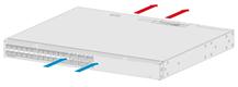
Removable fan tray LSPM1FANSA-SN |
From the power module side to the port side (S6812-24X6C switch as an example)
|
|
Removable fan tray LSPM1FANSB-SN |
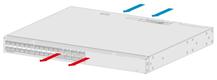
From the port side to the power module side (S6812-24X6C switch as an example)
|