- Table of Contents
-
- 03-Layer 2—LAN Switching Configuration Guide
- 00-Preface
- 01-Ethernet interface configuration
- 02-Loopback, null, and inloopback interface configuration
- 03-Bulk interface configuration
- 04-MAC address table configuration
- 05-Ethernet link aggregation configuration
- 06-DRNI configuration
- 07-Port isolation configuration
- 08-VLAN configuration
- 09-MVRP configuration
- 10-QinQ configuration
- 11-VLAN mapping configuration
- 12-Loop detection configuration
- 13-Spanning tree configuration
- 14-LLDP configuration
- 15-L2PT configuration
- 16-PPPoE relay configuration
- 17-Service loopback group configuration
- Related Documents
-
| Title | Size | Download |
|---|---|---|
| 12-Loop detection configuration | 237.56 KB |
Contents
Interface status auto recovery
Restriction and guidelines: DRNI configuration
Loop detection tasks at a glance
Restrictions and guidelines for loop detection configuration
Enabling loop detection globally
Enabling loop detection on an interface
Setting the loop protection action
Restrictions and guidelines for loop protection action configuration
Setting the global loop protection action
Setting the loop protection action on an interface
Setting the loop detection interval
Setting the loop protection delay timer
Restrictions and guidelines for loop protection delay timer configuration
Setting the global loop protection delay timer
Setting the loop protection delay timer on an interface
Display and maintenance commands for loop detection
Loop detection configuration examples
Example: Configuring basic loop detection functions
Example: Configuring loop detection on a DR system
Configuring loop detection in a VXLAN network
About loop detection in a VXLAN network
Restrictions and guidelines: VXLAN restrictions
VXLAN loop detection tasks at a glance
Enabling loop detection in a VXLAN network
Setting the loop protection action
Setting the loop detection interval
Setting the priority value in the loop detection priority
Display and maintenance commands for VXLAN loop detection
VXLAN loop detection configuration examples
Example: Configuring local site loop detection
Configuring loop detection
About loop detection
The loop detection mechanism performs periodic checking for Layer 2 loops. The mechanism immediately generates a log when a loop occurs so that you are promptly notified to adjust network connections and configurations. You can configure loop detection to shut down the looped interface. Logs are maintained in the information center. For more information, see Network Management and Monitoring Configuration Guide.
Loop detection mechanism
The device detects loops by sending detection frames and then checking whether these frames return to any interface on the device. If they do, the device considers that the interface is on a looped link.
Loop detection usually works within a VLAN. If a detection frame is returned with a different VLAN tag than it was sent out with, an inter-VLAN loop has occurred. To remove the loop, examine the QinQ or VLAN mapping configuration for incorrect settings. For more information about QinQ and VLAN mapping, see "Configuring QinQ" and "Configuring VLAN mapping."
Figure 1 Ethernet frame header for loop detection
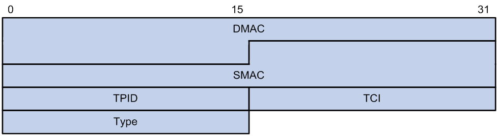
The Ethernet frame header of a loop detection packet contains the following fields:
· DMAC—Destination MAC address of the frame, which is the multicast MAC address 010f-e200-0007. When a loop detection-enabled device receives a frame with this destination MAC address, it performs the following operations:
¡ Sends the frame to the CPU.
¡ Floods the frame in the VLAN from which the frame was originally received.
· SMAC—Source MAC address of the frame, which is the bridge MAC address of the sending device.
· TPID—Type of the VLAN tag, with the value of 0x8100.
· TCI—Information of the VLAN tag, including the priority and VLAN ID.
· Type—Protocol type, with the value of 0x8918.
Figure 2 Inner frame header for loop detection
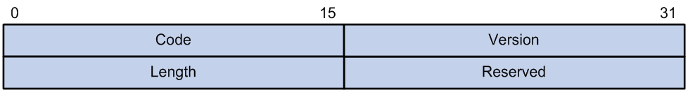
The inner frame header of a loop detection packet contains the following fields:
· Code—Protocol sub-type, which is 0x0001, indicating the loop detection protocol.
· Version—Protocol version, which is always 0x0000.
· Length—Length of the frame. The value includes the inner header, but excludes the Ethernet header.
· Reserved—This field is reserved.
Frames for loop detection are encapsulated as TLV triplets.
Table 1 TLVs supported by loop detection
|
TLV |
Description |
Remarks |
|
End of PDU |
End of a PDU. |
Optional. |
|
Device ID |
Bridge MAC address of the sending device. |
Required. |
|
Port ID |
ID of the PDU sending interface. |
Optional. |
|
Port Name |
Name of the PDU sending interface. |
Optional. |
|
System Name |
Device name. |
Optional. |
|
Chassis ID |
Chassis ID of the sending interface. |
Optional. |
|
Slot ID |
Slot ID of the sending interface. |
Optional. |
|
Sub Slot ID |
Sub-slot ID of the sending interface. |
Optional. |
Loop detection interval
Loop protection actions
When the device detects a loop on an interface, it generates a log but performs no action on the interface by default. You can configure the device to take one of the following actions:
· Block—Disables the interface from learning MAC addresses and blocks the interface.
· No-learning—Disables the interface from learning MAC addresses.
· Shutdown—Shuts down the interface to disable it from receiving and sending any frames.
Loop protection delay
The loop protection delay enables the device to wait for a period of time before taking loop protection actions on looped interfaces. On a network protected by loop detection, the shutdown or block action taken on a looped interface of an upstream device might cause traffic interruption to its downstream devices. To minimize the impacts of loop detection on downstream traffic, set the loop protection delay on the upstream devices. This delay allows the downstream devices to remove loops before the upstream devices take an action.
Interface status auto recovery
When the device configured with the block or no-learning loop action detects a loop on an interface, it performs the action and waits three loop detection intervals. If the device does not receive a loop detection frame within three loop detection intervals, it performs the following operations:
· Automatically sets the interface to the forwarding state.
· Notifies the user of the event.
When the device configured with the shutdown action detects a loop on an interface, the following events occur:
1. The device automatically shuts down the interface.
2. The device automatically sets the interface to the forwarding state after the detection timer set by using the shutdown-interval command expires. For more information about the shutdown-interval command, see Fundamentals Command Reference.
3. The device shuts down the interface again if a loop is still detected on the interface when the detection timer expires.
This process is repeated until the loop is removed.
|
|
NOTE: Incorrect recovery can occur when loop detection frames are discarded to reduce the load. To avoid this, use the shutdown action, or manually remove the loop. |
Restriction and guidelines: DRNI configuration
Member devices in a DR system must have the same loop detection configuration.
Loop detection tasks at a glance
To configure loop detection, perform the following tasks:
¡ Enabling loop detection globally
¡ Enabling loop detection on an interface
2. (Optional) Setting the loop protection action
¡ Setting the global loop protection action
¡ Setting the loop protection action on an interface
3. (Optional) Setting the loop detection interval
4. (Optional) Setting the loop protection delay timer
¡ Setting the global loop protection delay timer
¡ Setting the loop protection delay timer on an interface
Enabling loop detection
Restrictions and guidelines for loop detection configuration
You can enable loop detection globally or on a per-interface basis. When an interface receives a detection frame in any VLAN, the loop protection action is triggered on that interface, regardless of whether loop detection is enabled on it.
The loop detection feature is mutually exclusive with Layer 2 loop prevention features, including:
· The spanning tree feature.
· RRPP.
· ERPS.
To avoid unexpected network issues, do not use the loop detection feature and any of those Layer 2 loop prevention features together. For more information about the spanning tree feature, see "Configuring spanning tree protocols." For more information about RRPP and ERPS, see High Availability Configuration Guide.
Enabling loop detection globally
1. Enter system view.
system-view
2. Globally enable loop detection.
loopback-detection global enable vlan { vlan-id--list | all }
By default, loop detection is globally disabled.
Enabling loop detection on an interface
1. Enter system view.
system-view
2. Enter Layer 2 Ethernet interface view or Layer 2 aggregate interface view.
interface interface-type interface-number
3. Enable loop detection on the interface.
loopback-detection enable vlan { vlan-id--list | all }
By default, loop detection is disabled on interfaces.
Setting the loop protection action
Restrictions and guidelines for loop protection action configuration
You can set the loop protection action globally or on a per-interface basis. The global action applies to all interfaces. An interface-specific action applies to the interface on which it is configured. On an interface, the interface-specific action takes precedence over the global action.
Setting the global loop protection action
1. Enter system view.
system-view
2. Set the global loop protection action.
loopback-detection global action shutdown
By default, the device generates a log but performs no action on the interface on which a loop is detected.
Setting the loop protection action on an interface
1. Enter system view.
system-view
2. Enter interface view.
interface interface-type interface-number
3. Set the loop protection action on the interface.
loopback-detection action { block | no-learning | shutdown }
By default, the device generates a log but performs no action on the interface on which a loop is detected.
Support for the keywords of this command varies by interface type. For more information, see Layer 2—LAN Switching Command Reference.
Setting the loop detection interval
About this task
With loop detection enabled, the device sends loop detection frames at the loop detection interval. A shorter interval offers more sensitive detection but consumes more resources. Consider the system performance and loop detection speed when you set the loop detection interval.
Procedure
1. Enter system view.
system-view
2. Set the loop detection interval.
loopback-detection interval-time interval
The default setting is 30 seconds.
Setting the loop protection delay timer
Restrictions and guidelines for loop protection delay timer configuration
The global delay timer applies to all interfaces enabled with loop detection. An interface-specific delay timer applies to the interface on which it is configured. On an interface, the interface-specific delay timer takes precedence over the global delay timer.
To prevent interfaces from going down or coming up concurrently, set the loop protection delay timer to different values on different devices or on different interfaces of the same device.
Setting the global loop protection delay timer
1. Enter system view.
system-view
2. Set the global loop protection delay timer.
loopback-detection global delay-timer time
By default, loop protection delay is disabled globally.
Setting the loop protection delay timer on an interface
1. Enter system view.
system-view
2. Enter interface view.
interface interface-type interface-number
3. Set the loop protection delay timer on the interface.
loopback-detection global delay-timer time
By default, loop protection delay is disabled on an interface.
Display and maintenance commands for loop detection
Execute display commands in any view.
|
Task |
Command |
|
Display the loop detection configuration and status. |
display loopback-detection |
Loop detection configuration examples
Example: Configuring basic loop detection functions
Network configuration
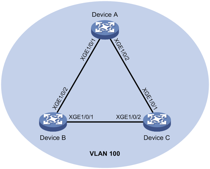
As shown in Figure 3, configure loop detection on Device A to meet the following requirements:
· Device A generates a log as a notification.
· Device A automatically shuts down the interface on which a loop is detected.
Procedure
1. Configure Device A:
# Create VLAN 100, and globally enable loop detection for the VLAN.
<DeviceA> system-view
[DeviceA] vlan 100
[DeviceA-vlan100] quit
[DeviceA] loopback-detection global enable vlan 100
# Configure Ten-GigabitEthernet 1/0/1 and Ten-GigabitEthernet 1/0/2 as trunk ports, and assign them to VLAN 100.
[DeviceA] interface Ten-GigabitEthernet 1/0/1
[DeviceA-Ten-GigabitEthernet1/0/1] port link-type trunk
[DeviceA-Ten-GigabitEthernet1/0/1] port trunk permit vlan 100
[DeviceA-Ten-GigabitEthernet1/0/1] quit
[DeviceA] interface ten-gigabitethernet 1/0/2
[DeviceA-Ten-GigabitEthernet1/0/2] port link-type trunk
[DeviceA-Ten-GigabitEthernet1/0/2] port trunk permit vlan 100
[DeviceA-Ten-GigabitEthernet1/0/2] quit
# Set the global loop protection action to shutdown.
[DeviceA] loopback-detection global action shutdown
# Set the loop detection interval to 35 seconds.
[DeviceA] loopback-detection interval-time 35
2. Configure Device B:
# Create VLAN 100.
<DeviceB> system-view
[DeviceB] vlan 100
[DeviceB–vlan100] quit
# Configure Ten-GigabitEthernet 1/0/1 and Ten-GigabitEthernet 1/0/2 as trunk ports, and assign them to VLAN 100.
[DeviceB] interface ten-gigabitethernet 1/0/1
[DeviceB-Ten-GigabitEthernet1/0/1] port link-type trunk
[DeviceB-Ten-GigabitEthernet1/0/1] port trunk permit vlan 100
[DeviceB-Ten-GigabitEthernet1/0/1] quit
[DeviceB] interface ten-gigabitethernet 1/0/2
[DeviceB-Ten-GigabitEthernet1/0/2] port link-type trunk
[DeviceB-Ten-GigabitEthernet1/0/2] port trunk permit vlan 100
[DeviceB-Ten-GigabitEthernet1/0/2] quit
3. Configure Device C:
# Create VLAN 100.
<DeviceC> system-view
[DeviceC] vlan 100
[DeviceC–vlan100] quit
# Configure Ten-GigabitEthernet 1/0/1 and Ten-GigabitEthernet 1/0/2 as trunk ports, and assign them to VLAN 100.
[DeviceC] interface ten-gigabitethernet 1/0/1
[DeviceC-Ten-GigabitEthernet1/0/1] port link-type trunk
[DeviceC-Ten-GigabitEthernet1/0/1] port trunk permit vlan 100
[DeviceC-Ten-GigabitEthernet1/0/1] quit
[DeviceC] interface ten-gigabitethernet 1/0/2
[DeviceC-Ten-GigabitEthernet1/0/2] port link-type trunk
[DeviceC-Ten-GigabitEthernet1/0/2] port trunk permit vlan 100
[DeviceC-Ten-GigabitEthernet1/0/2] quit
Verifying the configuration
# View the system logs on devices, for example, Device A.
[DeviceA]
%Feb 24 15:04:29:663 2019 DeviceA LPDT/4/LPDT_LOOPED: A loop was detected on Ten-GigabitEthernet1/0/1.
%Feb 24 15:04:29:664 2019 DeviceA LPDT/4/LPDT_VLAN_LOOPED: A loop was detected on Ten-GigabitEthernet1/0/1 in VLAN 100.
%Feb 24 15:04:29:667 2019 DeviceA LPDT/4/LPDT_LOOPED: A loop was detected on Ten-GigabitEthernet1/0/2.
%Feb 24 15:04:29:668 2019 DeviceA LPDT/4/LPDT_VLAN_LOOPED: A loop was detected on Ten-GigabitEthernet1/0/2 in VLAN 100.
%Feb 24 15:04:44:243 2019 DeviceA LPDT/5/LPDT_VLAN_RECOVERED: A loop was removed on Ten-GigabitEthernet1/0/1 in VLAN 100.
%Feb 24 15:04:44:243 2019 DeviceA LPDT/5/LPDT_RECOVERED: All loops were removed on Ten-GigabitEthernet1/0/1.
%Feb 24 15:04:44:248 2019 DeviceA LPDT/5/LPDT_VLAN_RECOVERED: A loop was removed on Ten-GigabitEthernet1/0/2 in VLAN 100.
%Feb 24 15:04:44:248 2019 DeviceA LPDT/5/LPDT_RECOVERED: All loops were removed on Ten-GigabitEthernet1/0/2.
The output shows the following information:
· Device A detected loops on Ten-GigabitEthernet 1/0/1 and Ten-GigabitEthernet 1/0/2 within a loop detection interval.
· Loops on Ten-GigabitEthernet 1/0/1 and Ten-GigabitEthernet 1/0/2 were removed.
# Use the display loopback-detection command to display the loop detection configuration and status on devices, for example, Device A.
[DeviceA] display loopback-detection
Loop detection is enabled.
Global loop detection interval is 35 second(s).
Loop is detected on following interfaces:
Interface Action mode VLANs/VSI
Ten-GigabitEthernet1/0/1 Shutdown 100
Ten-GigabitEthernet1/0/2 Shutdown 100
The output shows that the device has removed the loops from Ten-GigabitEthernet 1/0/1 and Ten-GigabitEthernet 1/0/2 according to the shutdown action.
# Display the status of Ten-GigabitEthernet 1/0/1 on devices, for example, Device A.
[DeviceA] display interface ten-gigabitethernet 1/0/1
Ten-GigabitEthernet1/0/1 current state: DOWN (Loop detection down)
...
The output shows that Ten-GigabitEthernet 1/0/1 is already shut down by the loop detection module.
# Display the status of Ten-GigabitEthernet 1/0/2 on devices, for example, Device A.
[DeviceA] display interface ten-gigabitethernet 1/0/2
Ten-GigabitEthernet1/0/2 current state: DOWN (Loop detection down)
...
The output shows that Ten-GigabitEthernet 1/0/2 is already shut down by the loop detection module.
Example: Configuring loop detection on a DR system
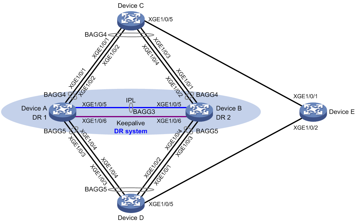
Network configuration
As shown in Figure 4, configure loop detection on the DR system formed by Device A and Device B to meet the following requirements:
· Generates a log as a notification.
· Automatically shuts down the interface on which a loop is detected.
Procedure
1. Configure Device A:
# Create VLAN 100.
<DeviceA> system-view
[DeviceA] vlan 100
[DeviceA-vlan100] quit
# Configure DR system settings.
[DeviceA] drni system-mac 1-1-1
[DeviceA] drni system-number 1
[DeviceA] drni system-priority 123
# Configure DR keepalive packet parameters.
[DeviceA] drni keepalive ip destination 1.1.1.1 source 1.1.1.2
# Set the link mode of Ten-GigabitEthernet 1/0/6 to Layer 3, and assign the interface an IP address. The IP address will be used as the source IP address of keepalive packets.
[DeviceA] interface ten-gigabitethernet 1/0/6
[DeviceA-Ten-GigabitEthernet1/0/6] port link-mode route
[DeviceA-Ten-GigabitEthernet1/0/6] ip address 1.1.1.2 24
[DeviceA-Ten-GigabitEthernet1/0/6] quit
# Exclude the interface used for DR keepalive detection (Ten-GigabitEthernet 1/0/6) from the shutdown action by DRNI MAD.
[DeviceA] drni mad exclude interface ten-gigabitethernet 1/0/6
# Create Layer 2 dynamic aggregate interface Bridge-Aggregation 3, and specify it as the IPP.
[DeviceA] interface bridge-aggregation 3
[DeviceA-Bridge-Aggregation3] link-aggregation mode dynamic
[DeviceA-Bridge-Aggregation3] port drni intra-portal-port 1
[DeviceA-Bridge-Aggregation3] quit
# Assign Ten-GigabitEthernet 1/0/5 to aggregation group 3.
[DeviceA] interface ten-gigabitethernet 1/0/5
[DeviceA-Ten-GigabitEthernet1/0/5] port link-aggregation group 3
[DeviceA-Ten-GigabitEthernet1/0/5] quit
# Set the link type of Bridge-Aggregation 3 to trunk, and assign it to VLAN 100.
[DeviceA] interface bridge-aggregation 3
[DeviceA-Bridge-Aggregation3] port link-type trunk
[DeviceA-Bridge-Aggregation3] port trunk permit vlan 100
[DeviceA-Bridge-Aggregation3] quit
# Create Layer 2 dynamic aggregate interface Bridge-Aggregation 4, and assign it to DR group 4.
[DeviceA] interface bridge-aggregation 4
[DeviceA-Bridge-Aggregation4] link-aggregation mode dynamic
[DeviceA-Bridge-Aggregation4] port drni group 4
[DeviceA-Bridge-Aggregation4] quit
# Assign Ten-GigabitEthernet 1/0/1 and Ten-GigabitEthernet 1/0/2 to aggregation group 4.
[DeviceA] interface ten-gigabitethernet 1/0/1
[DeviceA-Ten-GigabitEthernet1/0/1] port link-aggregation group 4
[DeviceA-Ten-GigabitEthernet1/0/1] quit
[DeviceA] interface ten-gigabitethernet 1/0/2
[DeviceA-Ten-GigabitEthernet1/0/2] port link-aggregation group 4
[DeviceA-Ten-GigabitEthernet1/0/2] quit
# Set the link type of Bridge-Aggregation 4 to trunk, and assign it to VLAN 100.
[DeviceA] interface bridge-aggregation 4
[DeviceA-Bridge-Aggregation4] port link-type trunk
[DeviceA-Bridge-Aggregation4] port trunk permit vlan 100
[DeviceA-Bridge-Aggregation4] quit
# Create Layer 2 dynamic aggregate interface Bridge-Aggregation 5, and assign it to DR group 5.
[DeviceA] interface bridge-aggregation 5
[DeviceA-Bridge-Aggregation5] link-aggregation mode dynamic
[DeviceA-Bridge-Aggregation5] port drni group 5
[DeviceA-Bridge-Aggregation5] quit
# Assign Ten-GigabitEthernet 1/0/3 and Ten-GigabitEthernet 1/0/4 to aggregation group 5.
[DeviceA] interface ten-gigabitethernet 1/0/3
[DeviceA-Ten-GigabitEthernet1/0/3] port link-aggregation group 5
[DeviceA-Ten-GigabitEthernet1/0/3] quit
[DeviceA] interface ten-gigabitethernet 1/0/4
[DeviceA-Ten-GigabitEthernet1/0/4] port link-aggregation group 5
[DeviceA-Ten-GigabitEthernet1/0/4] quit
# Set the link type of Bridge-Aggregation 5 to trunk, and assign it to VLAN 100.
[DeviceA] interface bridge-aggregation 5
[DeviceA-Bridge-Aggregation5] port link-type trunk
[DeviceA-Bridge-Aggregation5] port trunk permit vlan 100
[DeviceA-Bridge-Aggregation5] quit
# Disable the spanning tree feature.
[DeviceA] undo stp global enable
# Enable loop detection for VLAN 100 globally, set the global loop protection action to shutdown, and set the loop detection interval to 35 seconds.
[DeviceA] loopback-detection global enable vlan 100
[DeviceA] loopback-detection global action shutdown
[DeviceA] loopback-detection interval-time 35
2. Configure Device B in the same way Device A is configured. Set the DR system number to 2, and set the source and destination IP addresses of keepalive packets to 1.1.1.1 and 1.1.1.2, respectively. (Details not shown.)
3. Configure Device C:
# Disable the spanning tree feature.
<DeviceC> system-view
[DeviceC] undo stp global enable
# Create VLAN 100.
[DeviceC] vlan 100
[DeviceC-vlan100] quit
# Create Layer 2 dynamic aggregate interface Bridge-Aggregation 4.
[DeviceC] interface bridge-aggregation 4
[DeviceC-Bridge-Aggregation4] link-aggregation mode dynamic
[DeviceC-Bridge-Aggregation4] quit
# Assign Ten-GigabitEthernet 1/0/1 through Ten-GigabitEthernet 1/0/4 to aggregation group 4.
[DeviceC] interface range ten-gigabitethernet 1/0/1 to ten-gigabitethernet 1/0/4
[DeviceC-if-range] port link-aggregation group 4
[DeviceC-if-range] quit
# Set the link type of Bridge-Aggregation 4 to trunk, and assign it to VLAN 100.
[DeviceC] interface bridge-aggregation 4
[DeviceC-Bridge-Aggregation4] port link-type trunk
[DeviceC-Bridge-Aggregation4] port trunk permit vlan 100
[DeviceC-Bridge-Aggregation4] quit
# Set the link type of Ten-GigabitEthernet 1/0/5 to trunk, and assign it to VLAN 100.
[DeviceC] interface ten-gigabitethernet 1/0/5
[DeviceC-Ten-GigabitEthernet1/0/5] port link-type trunk
[DeviceC-Ten-GigabitEthernet1/0/5] port trunk permit vlan 100
[DeviceC-Ten-GigabitEthernet1/0/5] quit
4. Configure Device D:
# Disable the spanning tree feature.
<DeviceD> system-view
[DeviceD] undo stp global enable
# Create VLAN 100.
[DeviceD] vlan 100
[DeviceD-vlan100] quit
# Create Layer 2 dynamic aggregate interface Bridge-Aggregation 5.
[DeviceD] interface bridge-aggregation 5
[DeviceD-Bridge-Aggregation5] link-aggregation mode dynamic
[DeviceD-Bridge-Aggregation5] quit
# Assign Ten-GigabitEthernet 1/0/1 through Ten-GigabitEthernet 1/0/4 to aggregation group 5.
[DeviceD] interface range ten-gigabitethernet 1/0/1 to ten-gigabitethernet 1/0/4
[DeviceD-if-range] port link-aggregation group 5
[DeviceD-if-range] quit
# Set the link type of Bridge-Aggregation 5 to trunk, and assign it to VLAN 100.
[DeviceD] interface bridge-aggregation 5
[DeviceD-Bridge-Aggregation5] port link-type trunk
[DeviceD-Bridge-Aggregation5] port trunk permit vlan 100
[DeviceD-Bridge-Aggregation5] quit
# Set the link type of Ten-GigabitEthernet 1/0/5 to trunk, and assign it to VLAN 100.
[DeviceD] interface ten-gigabitethernet 1/0/5
[DeviceD-Ten-GigabitEthernet1/0/5] port link-type trunk
[DeviceD-Ten-GigabitEthernet1/0/5] port trunk permit vlan 100
[DeviceD-Ten-GigabitEthernet1/0/5] quit
5. Configure Device E:
# Disable the spanning tree feature.
<DeviceE> system-view
[DeviceE] undo stp global enable
# Create VLAN 100.
[DeviceE] vlan 100
[DeviceE-vlan100] quit
# Set the link type of Ten-GigabitEthernet 1/0/1 and Ten-GigabitEthernet 1/0/2 to trunk, and assign them to VLAN 100.
[DeviceE] interface ten-gigabitethernet 1/0/1
[DeviceE-Ten-GigabitEthernet1/0/1] port link-type trunk
[DeviceE-Ten-GigabitEthernet1/0/1] port trunk permit vlan 100
[DeviceE-Ten-GigabitEthernet1/0/1] quit
[DeviceE] interface ten-gigabitethernet 1/0/2
[DeviceE-Ten-GigabitEthernet1/0/2] port link-type trunk
[DeviceE-Ten-GigabitEthernet1/0/2] port trunk permit vlan 100
[DeviceE-Ten-GigabitEthernet1/0/2] quit
Verifying the configuration
# View the system logs on Device A.
[DeviceA]
%Aug 1 03:28:48:110 2019 DeviceA LPDT/4/LPDT_LOOPED: A loop was detected on
Bridge-Aggregation4.
%Aug 1 03:28:48:191 2019 DeviceA LPDT/4/LPDT_VLAN_LOOPED: A loop was detect
ed on Bridge-Aggregation4 in VLAN 100.
%Aug 1 03:28:48:194 2019 DeviceA LPDT/4/LPDT_LOOPED: A loop was detected on
Bridge-Aggregation5.
%Aug 1 03:28:48:288 2019 DeviceA LPDT/4/LPDT_VLAN_LOOPED: A loop was detect
ed on Bridge-Aggregation5 in VLAN 100.
%Aug 1 03:28:48:290 2019 DeviceA LPDT/5/LPDT_VLAN_RECOVERED: A loop was rem
oved on Bridge-Aggregation4 in VLAN 100.
%Aug 1 03:28:48:291 2019 DeviceA LPDT/5/LPDT_RECOVERED: All loops were remo
ved on Bridge-Aggregation4.
%Aug 1 03:28:48:302 2019 DeviceA LPDT/5/LPDT_VLAN_RECOVERED: A loop was rem
oved on Bridge-Aggregation5 in VLAN 100.
%Aug 1 03:28:48:304 2019 DeviceA LPDT/5/LPDT_RECOVERED: All loops were remo
ved on Bridge-Aggregation5.
The output shows the following information:
· Device A detected loops on Bridge-Aggregation 4 and Bridge-Aggregation 5 within a loop detection interval.
· Loops on Bridge-Aggregation 4 and Bridge-Aggregation 5 were removed.
# Use the display loopback-detection command to display the loop detection configuration and status on Device A.
[DeviceA] display loopback-detection
Loop detection is enabled.
Global loop detection interval is 35 second(s).
Loop is detected on following interfaces:
Interface Action mode VLANs/VSI
Bridge-Aggregation4 Shutdown 100
Bridge-Aggregation5 Shutdown 100
The output shows that the device has removed the loops from Bridge-Aggregation 4 and Bridge-Aggregation 5 according to the shutdown action.
# Verify that Bridge-Aggregation 4 has been shut down by loop detection.
[DeviceA] display interface Bridge-Aggregation 4
Bridge-Aggregation4
Current state: DOWN (Loopback detection down)
…
# Verify that Bridge-Aggregation 5 has been shut down by loop detection.
[DeviceA] display interface Bridge-Aggregation 5
Bridge-Aggregation5
Current state: DOWN (Loopback detection down)
…
# Verify that loops have been removed on Device B. (Details not shown.)
Configuring loop detection in a VXLAN network
About loop detection in a VXLAN network
Loop detection periodically checks for Layer 2 loops in a VXLAN network. The mechanism immediately generates a log when a loop occurs so that you are promptly notified to adjust network connections and configurations. You can configure loop detection to block a looped attachment circuit (AC). Logs are maintained in the information center. For more information, see Network Management and Monitoring Configuration Guide.
Application scenario
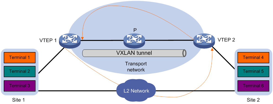
As shown in Figure 5, two VTEPs provide data transmission services for site 1 and site 2. Because the sites also have Layer 2 connectivity, broadcast storms can spread across the sites.
To remove loops from the VXLAN network, configure loop detection on the VTEPs. When a VTEP detects a loop on an AC, it blocks the AC to remove the loop.
Figure 5 Loop detection in a VXLAN network
Loop detection frame format
As shown in Figure 6, a loop detection frame contains the Ethernet header, loop detection header, and loop detection TLVs.
Figure 6 Loop detection frame format
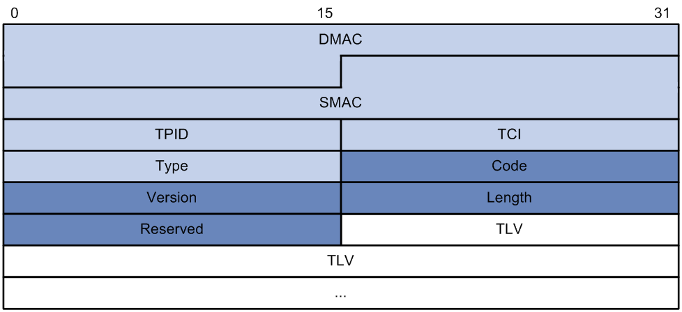
The Ethernet frame header of a loop detection frame contains the following fields:
· DMAC—Destination MAC address of the frame, which is the multicast MAC address 010f-e200-0007. When a loop detection-enabled device receives a frame with this destination MAC address, it performs the following operations:
¡ Sends the frame to the CPU.
¡ Floods the frame in the VLAN from which the frame was received.
· SMAC—Source MAC address of the frame, which is the bridge MAC address of the sending device.
· TPID—Type of the VLAN tag, with the default value of 0x8100.
· TCI—Tag control information, including the priority and VLAN ID.
· Type—Protocol type, with the value of 0x8918.
The loop detection header of a loop detection frame contains the following fields:
· Code—Protocol sub-type, which is 0x0001, indicating the loop detection type.
· Version—Protocol version, which is reserved. This field is fixed at 0x0000.
· Length—Length of the frame. The value includes the loop detection header, but excludes the Ethernet header.
· Reserved—This field is reserved.
Payload of a loop detection frame is encapsulated as TLV triplets.
Table 2 TLVs supported by loop detection
|
TLV |
Description |
Remarks |
|
End of PDU |
End of a PDU. |
Optional. |
|
Device ID |
Bridge MAC address of the sending device. |
Required. |
|
Port ID |
ID of the PDU sending interface. |
Optional. |
|
Port Name |
Name of the PDU sending interface. |
Optional. |
|
System Name |
Device name. |
Optional. |
|
Chassis ID |
Chassis ID of the sending interface. |
Optional. |
|
Slot ID |
Slot ID of the sending interface. |
Optional. |
|
Sub Slot ID |
Sub-slot ID of the sending interface. |
Optional. |
|
Priority |
Priority of the VSI mapped to the sending AC. |
Required. |
|
VXLAN ID |
VXLAN ID of the VSI mapped to the sending AC. |
Required. |
|
ACinfo |
Information about the sending AC. |
Required. |
|
DR ID |
DR group ID for the interface that hosts the sending AC. |
Optional. |
Loop detection priority
The loop detection frames sent by an AC carry the loop detection priority of the VSI mapped to the AC. The loop detection priority in a frame contains the priority value, the bridge MAC address, the AC's link ID, and DR group ID.
When an AC receives a loop detection frame, it compares its own loop detection priority with that in the frame to identify whether a loop exists.
· If the loop detection priority in the frame is higher, a loop exists and the loop protection action is triggered.
· If the loop detection priority of the AC is higher, the system only records the loop information.
When an AC receives a loop detection frame, the device uses the following comparison procedure to determine their loop detection priority:
1. Compares the priority values. The smaller the value, the higher the priority.
2. Compares the bridge MAC addresses if the priority values are the same. The lower bridge MAC address has higher priority.
3. If the bridge MAC addresses are the same, the system determines that the loop detection frame is sent by another AC on it. Then, the system perform the following comparisons to determine their priority:
¡ If DRNI is not configured, compares the link IDs. The smaller link ID has higher priority.
¡ If DRNI is configured, compares the DR group IDs or link IDs.
- If the receiving AC and the frame both have a DR group ID, the one with the larger ID has higher priority. This comparison occurs if the loop detection frame is sent and received by ACs that are on DR interfaces.
- If the receiving AC has a DR group ID but the frame does not contain one, the receiving AC has higher priority. If the frame contains a DR group ID, but the receiving AC does not have one, the frame has higher priority. This comparison occurs if the loop detection frame is sent or received by an AC on a non-DR interface.
- If both of them do not have DR group IDs, compares the link IDs. The smaller link ID has higher priority. This comparison occurs if the loop detection frame is sent and received by ACs that are on non-DR interfaces.
Loop detection mechanisms
After you enable loop detection on a VSI, its ACs keep sending loop detection frames and detecting incoming loop detection frames at the same time. If an AC receives a loop detection frame that carries a VXLAN ID the same as the AC's VXLAN ID, the device determines that a loop exists in the VXLAN. Then, the AC compares its own loop detection priority with that in the frame. If the loop detection priority in the frame is higher, the loop protection action is triggered. If the loop detection priority of the AC is higher, the system only records the loop information.
The ACs of a loop detection-enabled VSI send loop detection frames to detect loops in the attached sites. If the device receives a loop detection frame on a VXLAN tunnel interface and the VXLAN ID in the frame matches the local one, it determines that a loop exists on the traffic outgoing AC.
Loop detection is a continuous process as the network changes. Loop detection frames are sent at the loop detection interval to determine whether loops occur on ACs and whether loops are removed.
AC status auto recovery
When the device configured with the block action detects a loop on an AC, it generates a log, disables MAC address learning on the AC, and blocks the AC. If the device does not receive a loop detection frame on the blocked AC within three loop detection intervals, it performs the following actions:
· Automatically sets the AC to the forwarding state.
· Notifies the user of the event.
Restrictions and guidelines: VXLAN restrictions
Global loop detection settings do not take effect on VSIs.
Loop detection can operate on a VSI only if the ACs mapped to the VSI are Ethernet service instances.
VXLAN loop detection tasks at a glance
To configure loop detection in a VXLAN network, perform the following tasks:
1. Enabling loop detection in a VXLAN network
2. (Optional) Setting the loop protection action
3. (Optional) Setting the loop detection interval
4. (Optional) Setting the priority value in the loop detection priority
Enabling loop detection in a VXLAN network
1. Enter system view.
system-view
2. Enter VSI view.
vsi vsi-name
3. Enable loop detection. Choose one of the following options:
¡ Enable single-tagged loop detection.
loopback-detection enable [ vlan vlan-id-list ]
¡ Enable double-tagged loop detection.
loopback-detection enable s-vid vlan-id-list c-vid vlan-id-list
By default, loop detection is disabled on VSIs.
For loop detection to operate correctly, make sure the following access mode requirements are met:
¡ If you enable untagged loop detection on a VSI, make sure the ACs of the VSI use VLAN access mode.
¡ If you enable single-tagged or double-tagged loop detection on a VSI, make sure the ACs of the VSI use Ethernet access mode.
Setting the loop protection action
Restrictions and guidelines
The loop protection action set in VSI view takes effect on all ACs of a VSI.
Procedure
1. Enter system view.
system-view
2. Enter VSI view.
vsi vsi-name
3. Set the loop protection action.
loopback-detection action block
By default, the device generates a log but performs no action on the AC on which a loop is detected.
Setting the loop detection interval
About this task
With loop detection enabled, the device sends loop detection frames at the loopback detection interval. A shorter interval offers more sensitive detection but consumes more resources. Consider the system performance and loop detection speed when you set the loop detection interval.
A short loop detection interval might cause link flapping if the number of VSIs is large. As a best practice, increase the loop detection interval depending on the number of VSIs.
Procedure
1. Enter system view.
system-view
2. Enter VSI view.
vsi vsi-name
3. Set the loop detection interval.
loopback-detection interval-time interval
The default loop detection interval is 30 seconds.
Setting the priority value in the loop detection priority
About this task
Perform this task to configure the device to block ACs based on their priorities when loops are detected.
Procedure
1. Enter system view.
system-view
2. Enter VSI view.
vsi vsi-name
3. Set the priority value in the loop detection priority.
loopback-detection priority priority
By default, the priority value is 7 in the loop detection priority of a VSI.
Display and maintenance commands for VXLAN loop detection
Execute display commands in any view.
|
Task |
Command |
|
Display the loop detection configuration and status. |
display loopback-detection |
VXLAN loop detection configuration examples
Example: Configuring local site loop detection
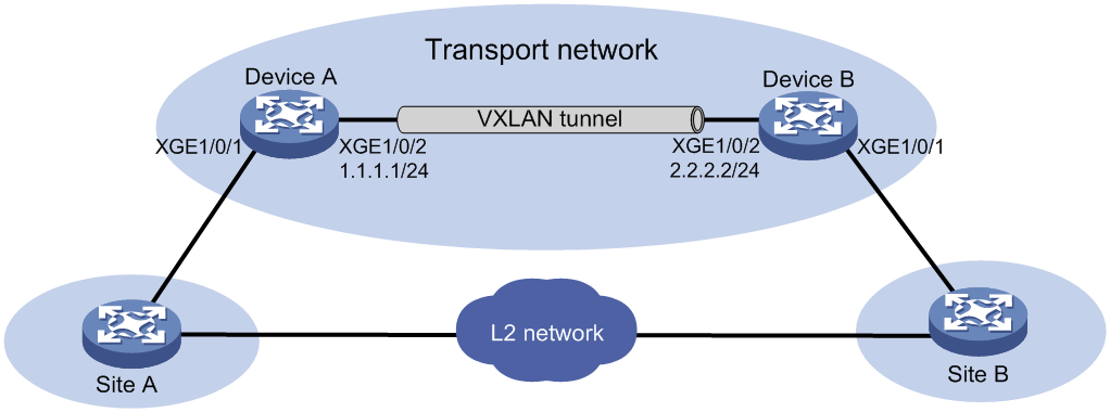
Network configuration
As shown in Figure 7, Device A and Device B provide user traffic transmission service for site 1 and site 2, and the sites have Layer 2 connectivity in VLAN 10. Configure loop detection on Device A and Device B so that they can block ACs if loops exist.
Prerequisites
Configure a routing protocol in the VXLAN for the VTEPs to reach one another.
Procedure
1. Configure Device A:
# Create VXLAN 1 and assign it a VXLAN tunnel. Map VSI vsi 1 to VXLAN 1.
<DeviceA> system-view
[DeviceA] l2vpn enable
[DeviceA] interface tunnel 0 mode vxlan
[DeviceA-Tunnel0] source 1.1.1.1
[DeviceA-Tunnel0] destination 2.2.2.2
[DeviceA-Tunnel0] quit
[DeviceA] vsi 1
[DeviceA-vsi-1] vxlan 1
[DeviceA-vsi-1-vxlan-1] tunnel 0
[DeviceA-vsi-1-vxlan-1] quit
# Disable spanning tree globally.
[DeviceA] undo stp global enable
# Configure an AC and map it to VSI vsi 1.
[DeviceA] interface ten-gigabitethernet 1/0/1
[DeviceA-Ten-GigabitEthernet1/0/1] service-instance 1
[DeviceA-Ten-GigabitEthernet1/0/1-srv1] encapsulation s-vid 10
[DeviceA-Ten-GigabitEthernet1/0/1-srv1] xconnect vsi 1
[DeviceA-Ten-GigabitEthernet1/0/1-srv1] quit
# Enable loop detection on VSI vsi 1.
[DeviceA] vsi 1
[DeviceA-vsi-1] loopback-detection enable
# Set the loop protection action to block on VSI vsi 1.
[DeviceA-vsi-1] loopback-detection action block
# Set the loop detection interval to 35 seconds on VSI vsi 1.
[DeviceA-vsi-1] loopback-detection interval-time 35
# Set the loop detection priority to 1 on VSI vsi 1.
[DeviceA-vsi-1] loopback-detection priority 1
2. Configure Device B:
# Create VXLAN 1 and assign it a VXLAN tunnel. Map VSI vsi 1 to VXLAN 1.
<DeviceB> system-view
[DeviceB] l2vpn enable
[DeviceB] interface Tunnel 0 mode vxlan
[DeviceB-Tunnel0] source 2.2.2.2
[DeviceB-Tunnel0] destination 1.1.1.1
[DeviceB-Tunnel0] quit
[DeviceB] vsi 1
[DeviceB-vsi-1] vxlan 1
[DeviceB-vsi-1-vxlan-1] tunnel 0
[DeviceB-vsi-1-vxlan-1] quit
# Disable spanning tree globally.
[DeviceB] undo stp global enable
# Configure an AC and map it to VSI vsi 1.
[DeviceB] interface ten-gigabitethernet 1/0/1
[DeviceB-Ten-GigabitEthernet1/0/1] service-instance 1
[DeviceB-Ten-GigabitEthernet1/0/1-srv1] encapsulation s-vid 10
[DeviceB-Ten-GigabitEthernet1/0/1-srv1] xconnect vsi 1
[DeviceB-Ten-GigabitEthernet1/0/1-srv1] quit
# Enable loop detection on VSI vsi 1.
[DeviceB] vsi 1
[DeviceB-vsi-1] loopback-detection enable
# Set the loop protection action to block on VSI vsi 1.
[DeviceB-vsi-1] loopback-detection action block
# Set the loop detection interval to 35 seconds on VSI vsi 1.
[DeviceB-vsi-1] loopback-detection interval-time 35
# Set the loop detection priority to 6 on VSI vsi 1.
[DeviceB-vsi-1] loopback-detection priority 6
Verifying the configuration
# Verify that Device A has detected a loop.
[DeviceA]
%Mar 25 10:59:59:690 2019 Device A LPDT/4/LPDT_VSI_LOOPED: A loop was detected on VSI 1's Ethernet service instance srv1 on Ten-GigabitEthernet1/0/1.
# Verify that Device A has detected a loop on the AC on Ten-GigabitEthernet 1/0/1 but does not block the AC because it has high priority.
[DeviceA] display loopback-detection
Loop detection is enabled.
Global loop detection interval is 30 second(s).
Loop is detected on following interfaces:
* indicates the loop protection action was not triggered.
# indicates the loop protection action failed.
Interface Action mode VLANs/VSI
Ten-Ten-GigabitEthernet1/0/1 srv1 Block* 1
# Verify that Device B has blocked the AC on Ten-GigabitEthernet 1/0/1 to remove the loop.
[DeviceB] display loopback-detection
Loop detection is enabled.
Global loop detection interval is 30 second(s).
Loop is detected on following interfaces:
* indicates the loop protection action was not triggered.
# indicates the loop protection action failed.
Interface Action mode VLANs/VSI
Ten-Ten-GigabitEthernet1/0/1 srv1 Block 1
