- Table of Contents
- Related Documents
-
| Title | Size | Download |
|---|---|---|
| 01-Text | 43.38 MB |
2 Inspecting the router at delivery
Determining the installation personnel
Installation site requirements
General safety recommendations
Attaching slide rails to the rack
Installing cable management brackets
Power trays and power supplies
DC power supply configuration guidelines
AC power supply configuration guidelines
Installing HVDC power supplies
HVDC power supply configuration guidelines
Installing an HVDC power supply
7 Installing removable components
Installing an interface module that uses detachable ejector levers
Installing an interface module that uses general ejector levers
Installing transceiver modules and optical fibers
Connecting an optical fiber to a multi-chassis fabric module
Cables for connecting E1 ports
Installing the top hood and air filter
1 Chassis overview
Chassis views
Figure 1-1 Front view
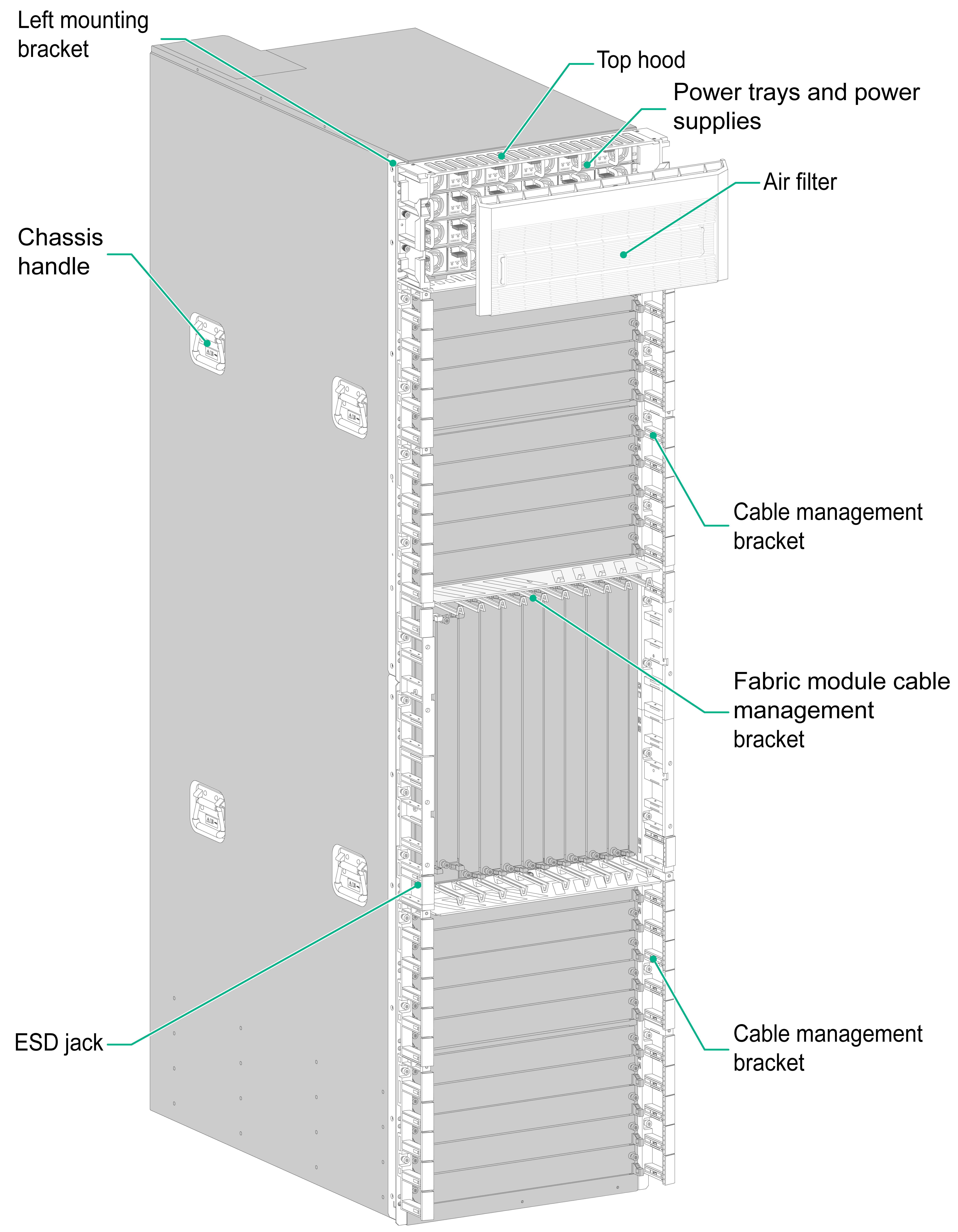
Figure 1-2 Rear view

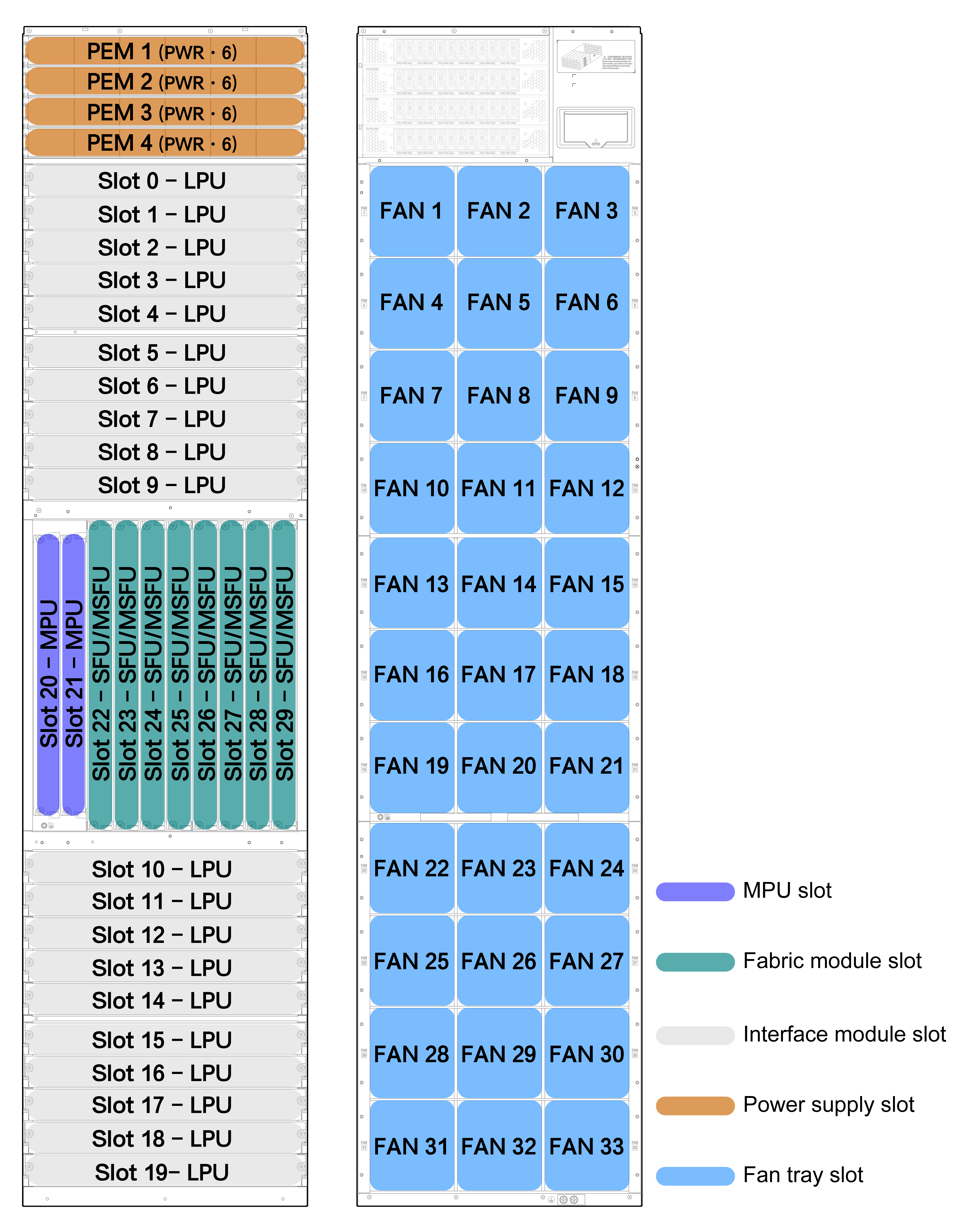
Slot arrangement
"LPU" in Figure 1-3 refers to an interface module, "SFU" refers to a single-chassis fabric module, "MSFU" refers to a multi-chassis fabric module, and "PEM" refers to a power tray.
2 Inspecting the router at delivery
When the router is delivered, inspect the items against the packing list. Make sure all items in the list are delivered in good condition. Keep the items secure for future use.
|
IMPORTANT: · Install the router after finishing inspection. Do not inspect the router when installing it. · Keep the packaging materials secure for future moving or shipment. · If you find a fault with the router before powering it on, stop your operation, keeping the router as it is, and take photos. Keep the original packaging materials and accessories secure. |
3 Preparing for installation
Determining the installation personnel
The personnel for installing and maintaining the router must have received professional training and are familiar with the precautions in installation and skilled and professional in router installation and maintenance.
Installation site requirements
Equipment room requirements
For correct operation of the router, make sure the equipment room meets the following requirements:
· The installation site has a good ventilation and cooling system.
· The air inlet and outlet vents of the chassis are not blocked, clear of obstructions.
· The air inlets vents of the chassis are away from the outlet vents of other devices.
· The ambient temperature for the router is maintained in the range of 0°C to 45°C (32°F to 113°F).
· The ambient humidity for the router is maintained in the range of 5% RH to 95 % RH, non-condensing.
· The equipment room is clean, dust-free, and can adequately keep the router from any form of potential water damage. If the equipment room environment is not clean enough, install air filters on the rack doors as a best practice.
Weight support requirements
Make sure the floor or ground at the installation site can support the combined weight of the router and the rack. The total weight of the router includes the chassis and its components (for example, modules, fan trays, power supplies, and cables) and accessories.
Grounding requirements
Correctly grounding the router is crucial to lightning protection, anti-interference, and ESD prevention. Use a good grounding system for the router. Make sure the resistance between the chassis and the ground is less than 1 ohm.
Space requirements
|
|
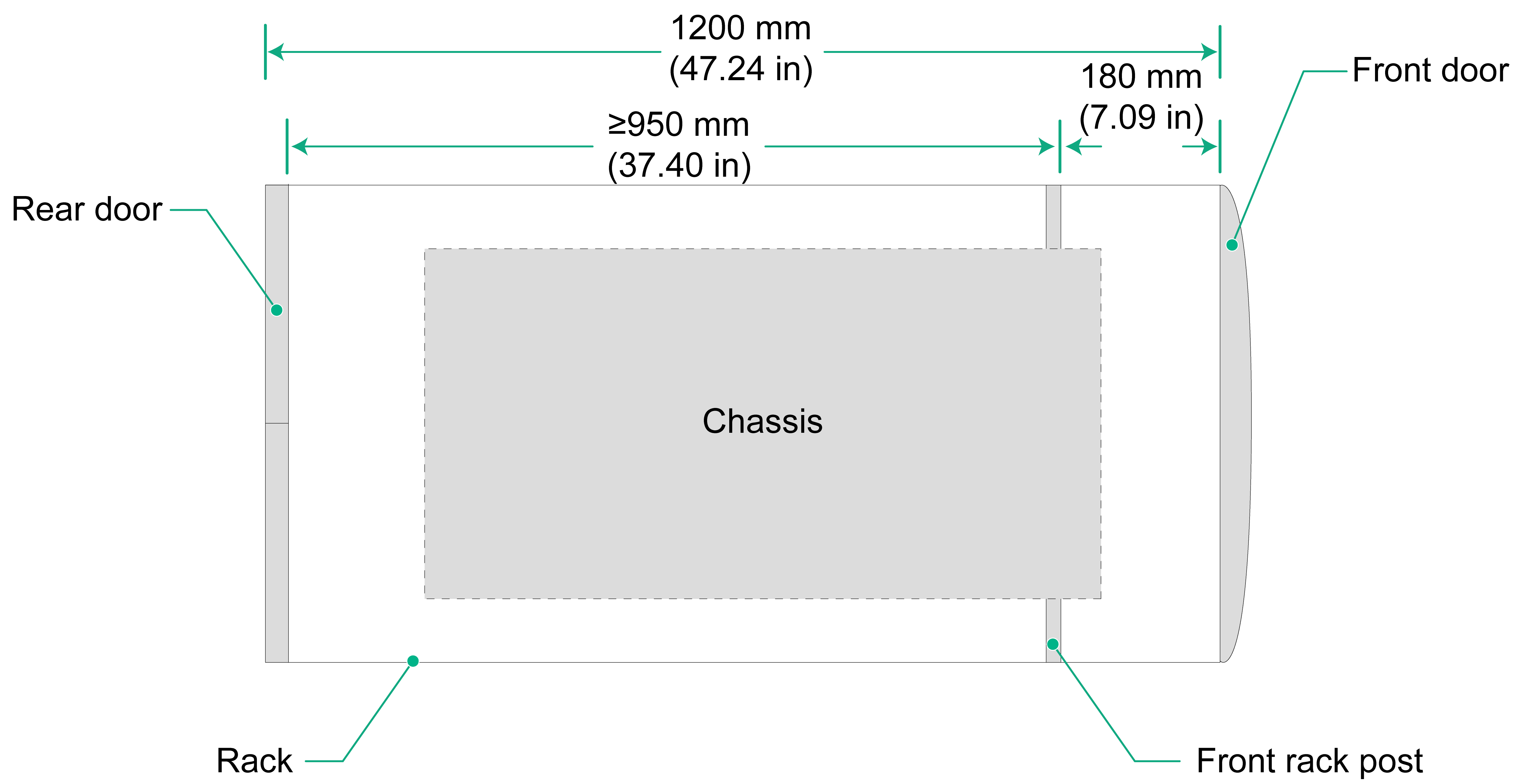
IMPORTANT: · For the chassis to be accessible from front and rear, use a rack that has both a front door (single-leaf door as a best practice) and rear door. · For easy installation and maintenance, reserve a minimum clearance of 1200 mm (47.24 in) between the rack and walls or other devices. |
Table 3-1 Router dimensions and rack requirements
|
Chassis dimensions |
Rack requirements |
|
· Height—1820 mm (71.65 in)/41 RU · Width—440 mm (17.32 in) · Depth—980 mm (38.58 in) ¡ Chassis—850 mm (33.46 in) ¡ Cable management bracket—90 mm (3.54 in) ¡ Fan tray handle at the rear—40 mm (1.57 in) |
As a best practice, use a rack that meets the following requirements: · With dimensions (H × W × D) of 2200 × 600 × 1200 mm (86.61 × 23.62 × 47.24 in) · 180 mm (7.09 in) from the front rack posts to the interior side of the front door when the router is fully configured with components and cables. You can reduce the distance between the front rack posts and the front door based on the actual configuration. · A minimum of 950 mm (37.40 in) from the front rack posts to the interior side of the rear door. |
Figure 3-1 Chassis dimension
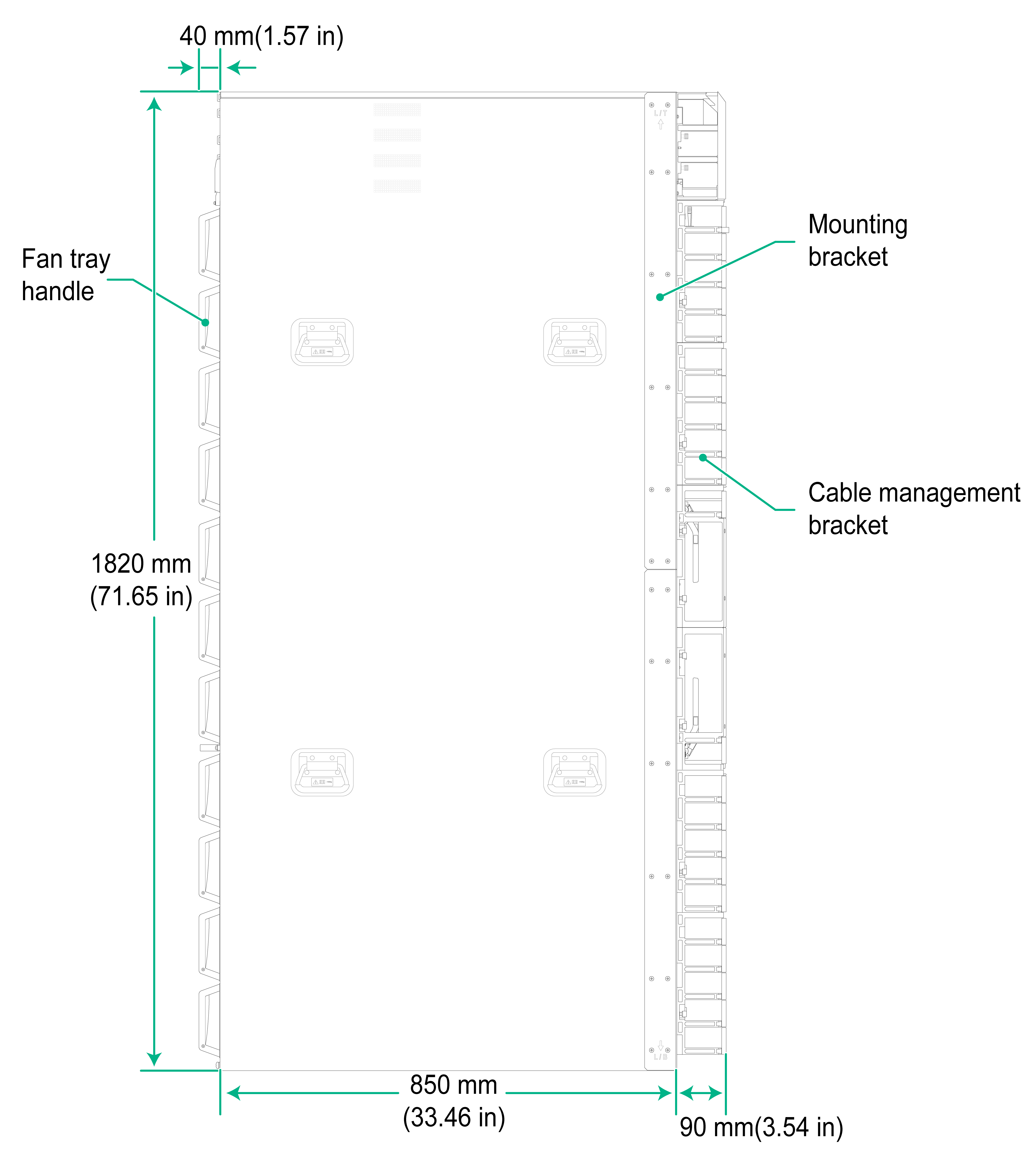
Figure 3-2 Rack requirements
Cooling requirements
|
|
CAUTION: · For adequate heat dissipation, make sure the air inlet and outlet vents of the router are not blocked and adequate clearance is reserved around the air vents. · Make sure the rack for the router has a good cooling system, with the perforation rate of rack doors greater than 50%. · Make sure the air conditioners do not blow air directly onto the router. |
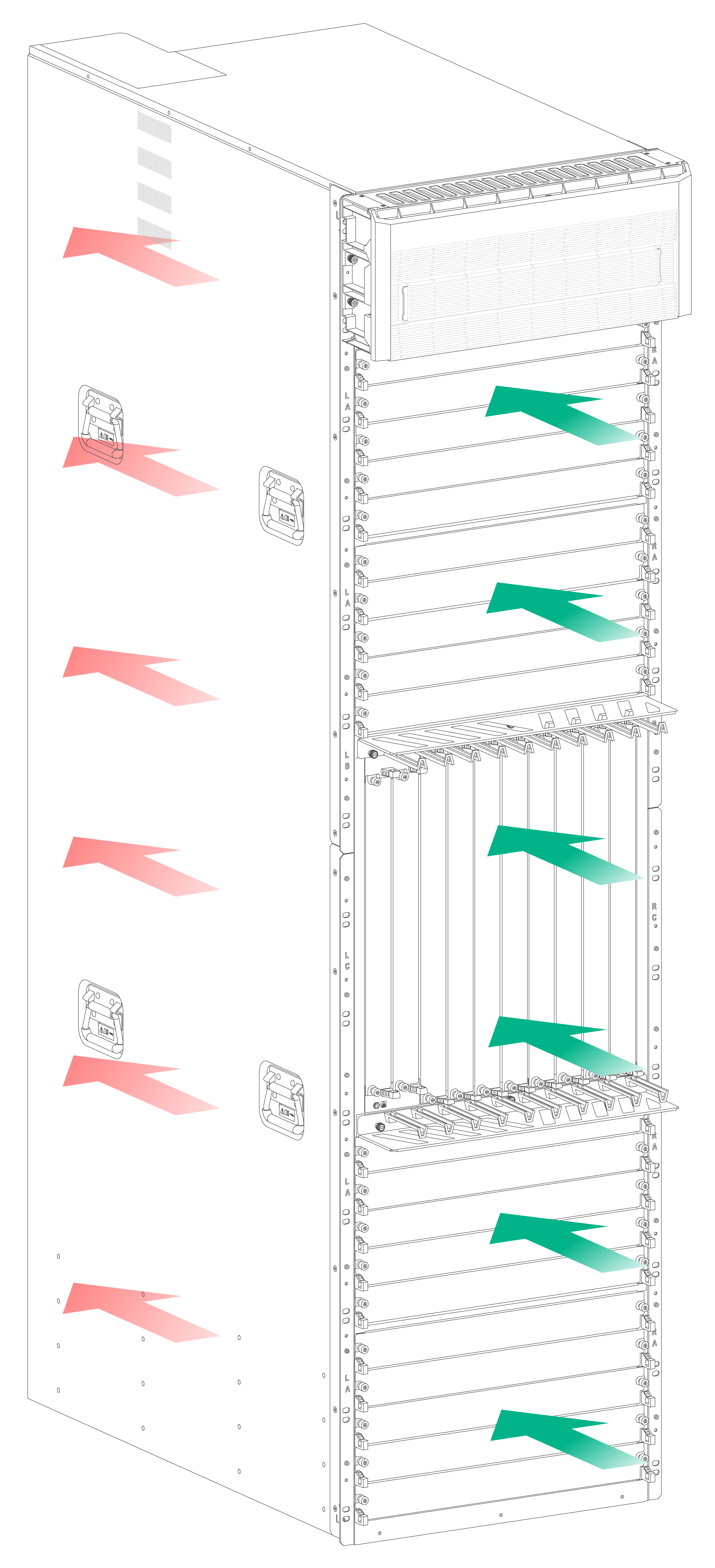
The router uses super-short cut-through air aisles to provide front-to-rear airflow for heat dissipation, as shown in Figure 3-3.
Figure 3-3 Airflow through the chassis
Safety recommendations
Safety symbols
When reading this document, pay special attention to the following symbols:
![]() WARNING means an alert that calls attention to important information that if
not understood or followed can result in personal injury.
WARNING means an alert that calls attention to important information that if
not understood or followed can result in personal injury.
![]() CAUTION means an alert that calls attention to important information that if
not understood or followed can result in data loss, data corruption, or damage
to hardware or software.
CAUTION means an alert that calls attention to important information that if
not understood or followed can result in data loss, data corruption, or damage
to hardware or software.
General safety recommendations
To avoid bodily injury or device damage, follow these guidelines when you install or operate the router:
· Keep the chassis and installation tools away from walk areas.
· Place the router on a dry, flat location. Make sure anti-slip measures are in place.
· When servicing the router, do not wear loose clothing or jewelry (such as a necklace) that could get caught in the chassis.
· If you cannot install a removable component smoothly, stop your operation and troubleshoot the issues, preventing component damages caused by misoperations.
· Clear the work area of any possible electricity hazards, such as ungrounded power extension cables, missing safety grounds, and wet floors.
· The router is 41U high. To use a ladder for router installation and maintenance, position the ladder securely and strictly follow the ladder safety rules .
· Locate the emergency power-off switch in the room before installation so that you can quickly shut power off when an electrical accident occurs.
· The router uses two power switches to achieve redundancy. The router is powered off only when both the power switches are turned off.
ESD prevention
To prevent components from ESD damage, wear an ESD wrist strap before working with the router and the modules.
To attach an ESD wrist strap:
1. Put the wrist band of the strap on your wrist and fasten the band so that it makes good contact with your skin.
2. Attach the other end of the strap to an ESD jack on the chassis or rack. Make sure the strap is reliably grounded.
The router has one ESD jack on both the front and rear panels.
Moving the chassis
Physical specifications
The shipping weight of the router includes the chassis and its packaging materials. Determine a moving method for the chassis based on its shipping weight.
Table 3-2 Physical specifications
|
Shipping weight (including filler panels and power trays) |
Dimensions (H × W × D) |
|
416 kg (917.11 lb) |
1820 × 440 × 850 mm (71.65 × 17.32 × 38.58 in) |
Moving the chassis
|
|
CAUTION: · To avoid damages, use only the chassis handles other than any other component to move the chassis. · When moving the chassis, do not tilt, put down, or drag the chassis. · Avoid bumping the chassis on doors, walls, or other objects when transporting, moving, and installing it. |
To move the chassis to the installation location:
1. Unpack the wooden ramp, place the ramp in front of the pallet, and use U-type fasteners to secure the ramp to the pallet front.
Figure 3-4 Securing the ramp to the pallet
2. Remove the foam cushions and anti-corrosion bags from the router and verify the following items:
¡ The router is intact without any signs of water soaking or corrosion.
¡ The labels on the chassis are correct, clear, and complete.
¡ The accessory box packages are intact.
¡ The accessories are good and in the correct quantity.
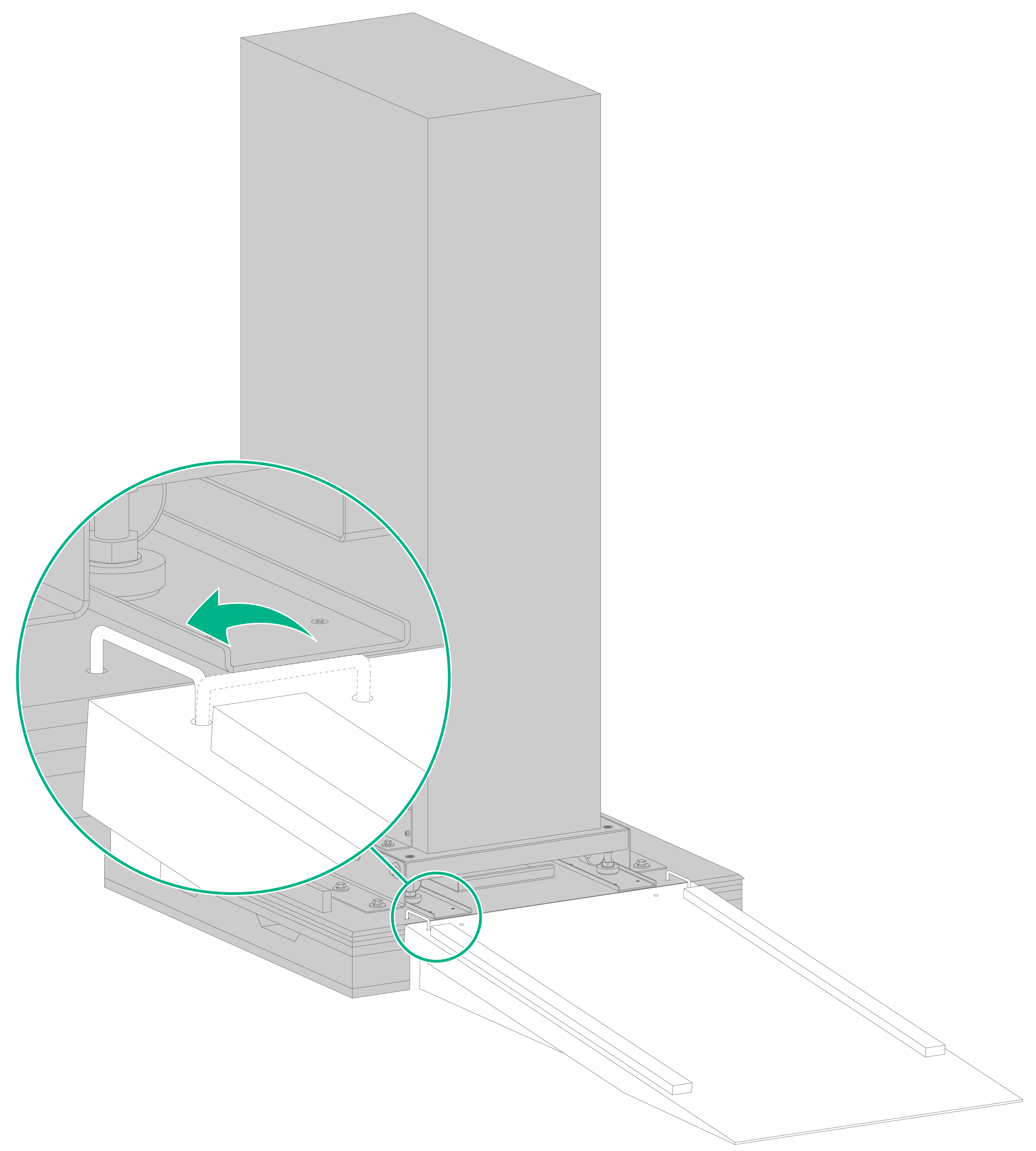
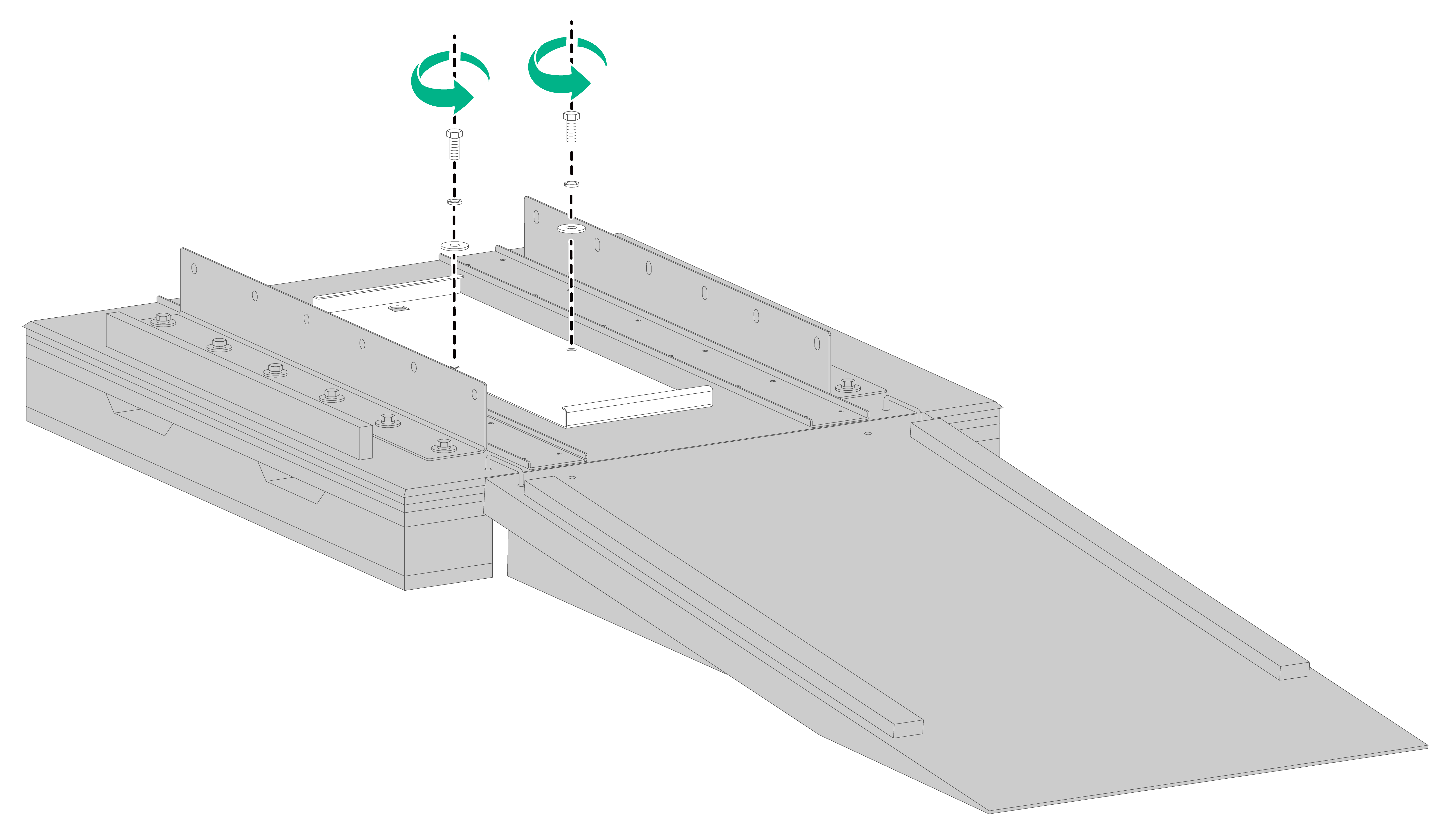
3. Use a wrench to remove the screws on the hold-down brackets that secure the dolly to the pallet, as shown in Figure 3-5.
Figure 3-5 Removing the screws on the hold-down brackets that secure the dolly to the pallet
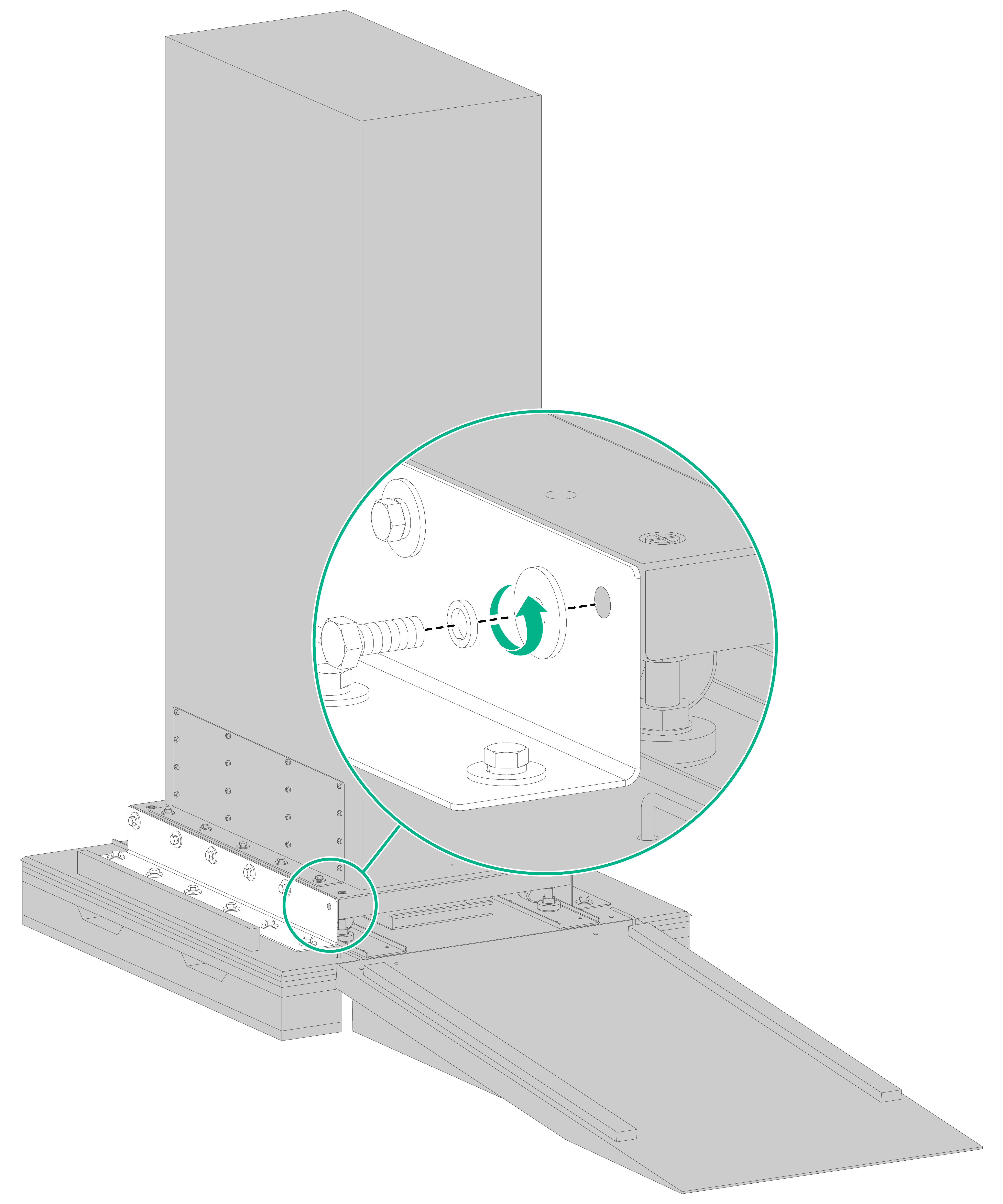
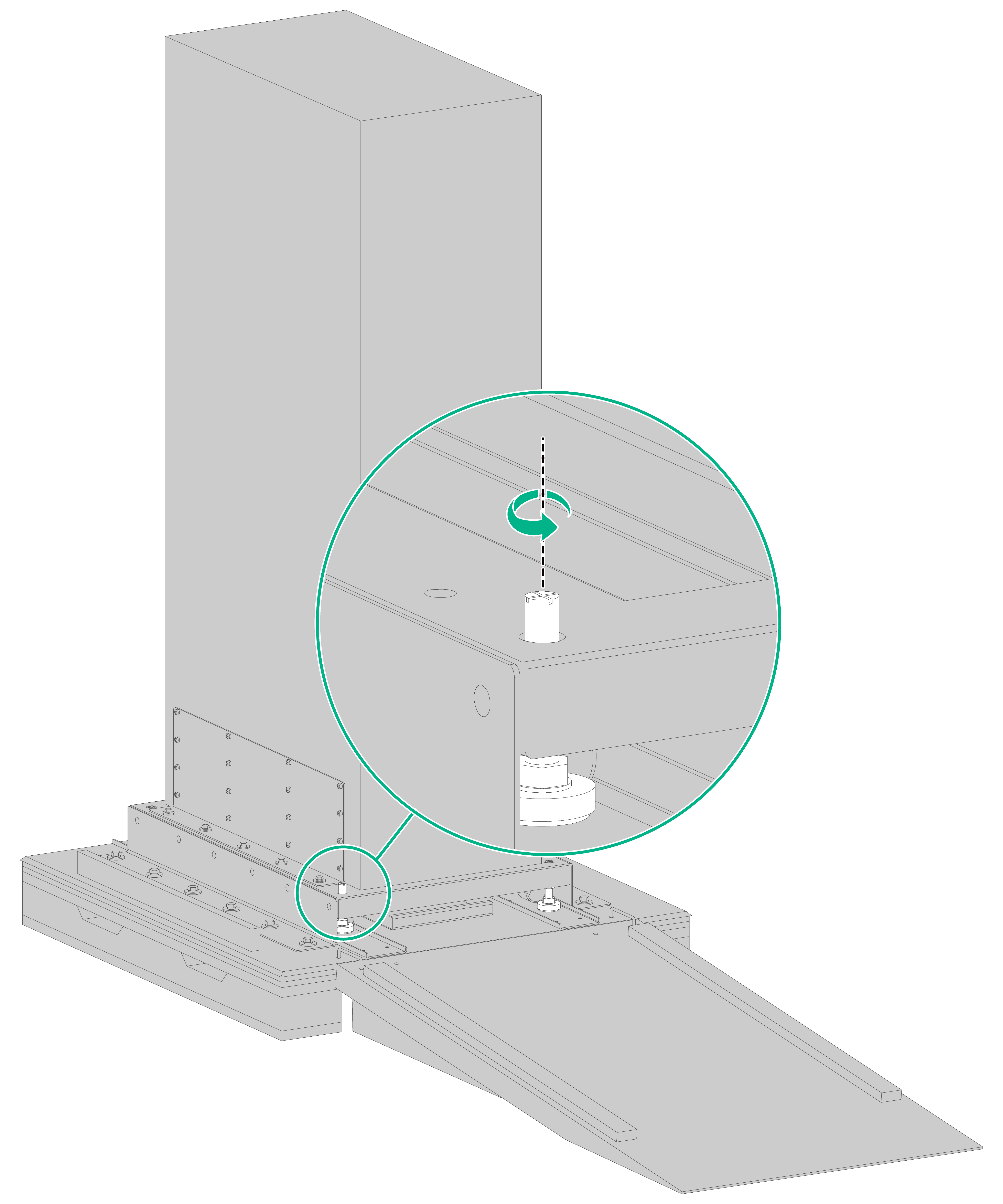
4. Adjust the levelling foot of the dolly so that the dolly wheels support the chassis, as shown in Figure 3-6.
Figure 3-6 Adjusting the levelling foot of the dolly
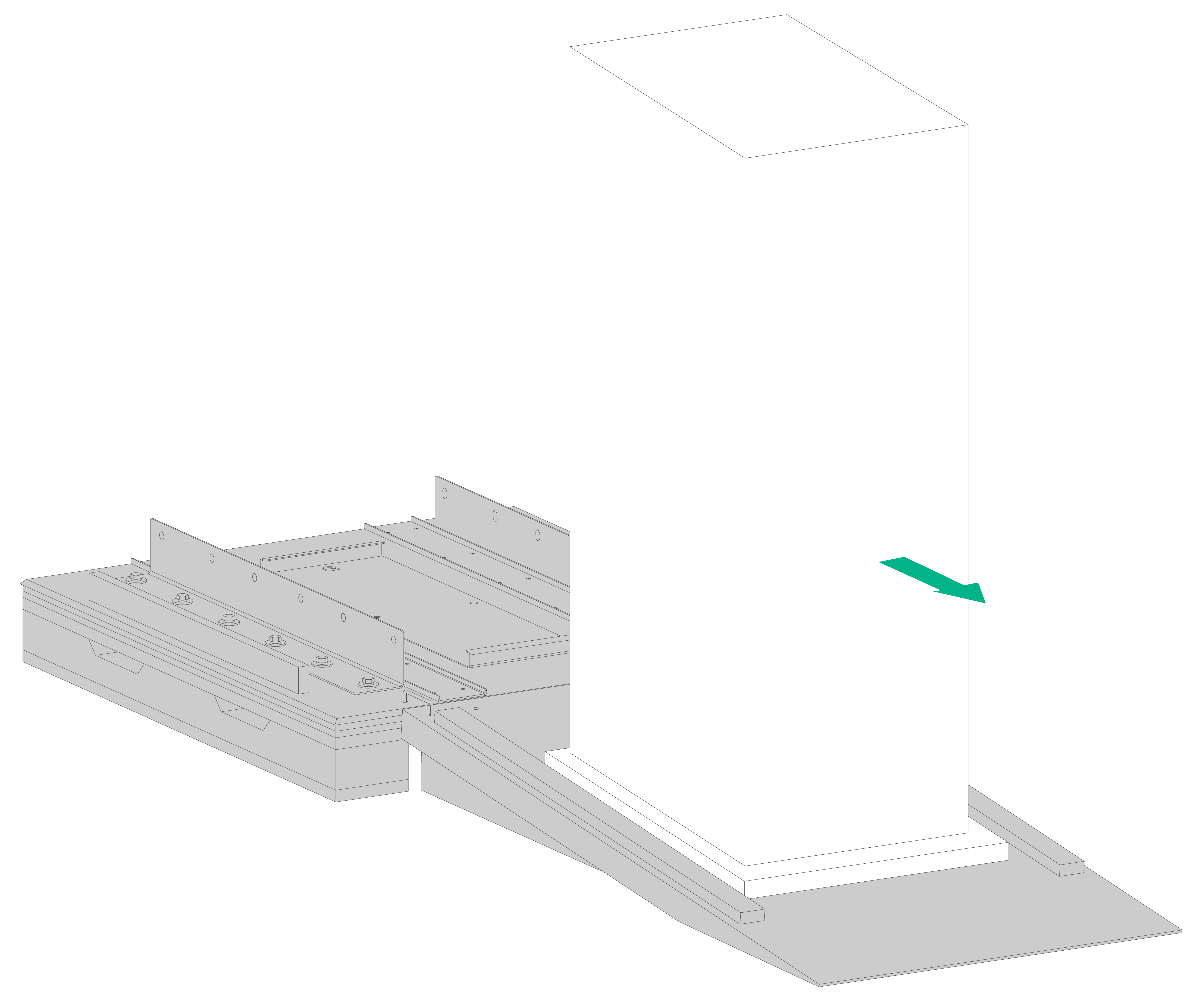
5. Push the chassis down over the wooden ramp slowly.
The router is high and heavy. As a best practice, use multiple people to push the chassis down.
Figure 3-7 Pushing the chassis down over the wooden ramp
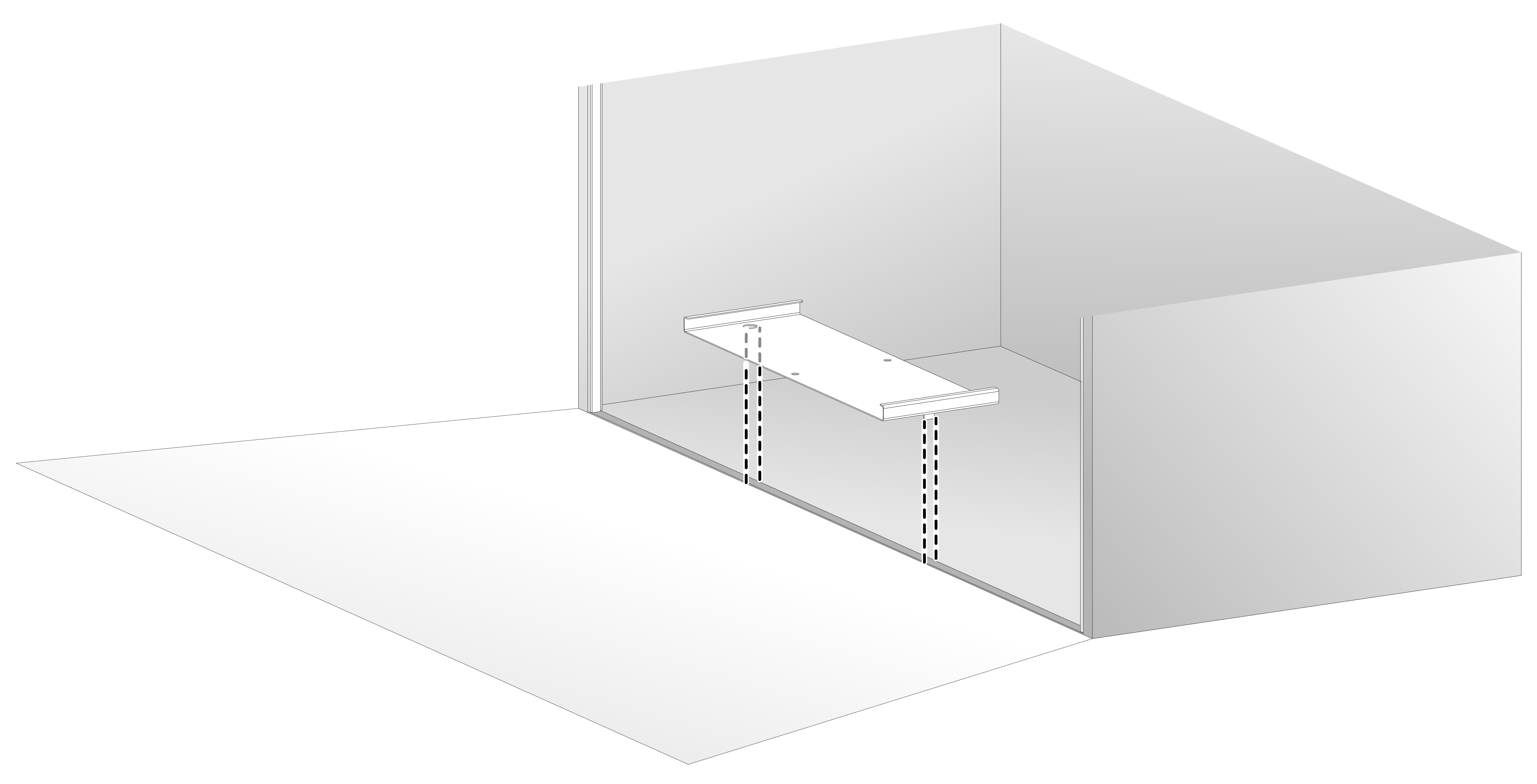
6. Detach the elevator bridge plate from the pallet and keep it secure.
Figure 3-8 Detaching the elevator bridge plate from the pallet
The elevator bridge plate (as shown in Figure 3-9) is required when you need to move the chassis in a freight elevator. Before moving the chassis in or out of a freight elevator, insert the pegs of the plate into the gap between the elevator car bottom edge and the landing floor edge so that the plate covers the gap, as shown in Figure 3-10. This prevents the dolly wheels from being stuck into the gap.
Figure 3-9 Elevator bridge plate

Figure 3-10 Using the elevator bridge plate in a freight elevator
7. Move the chassis to a location close to the installation location, and then lower down the levelling foot of the dolly so that the levelling feet support the chassis.
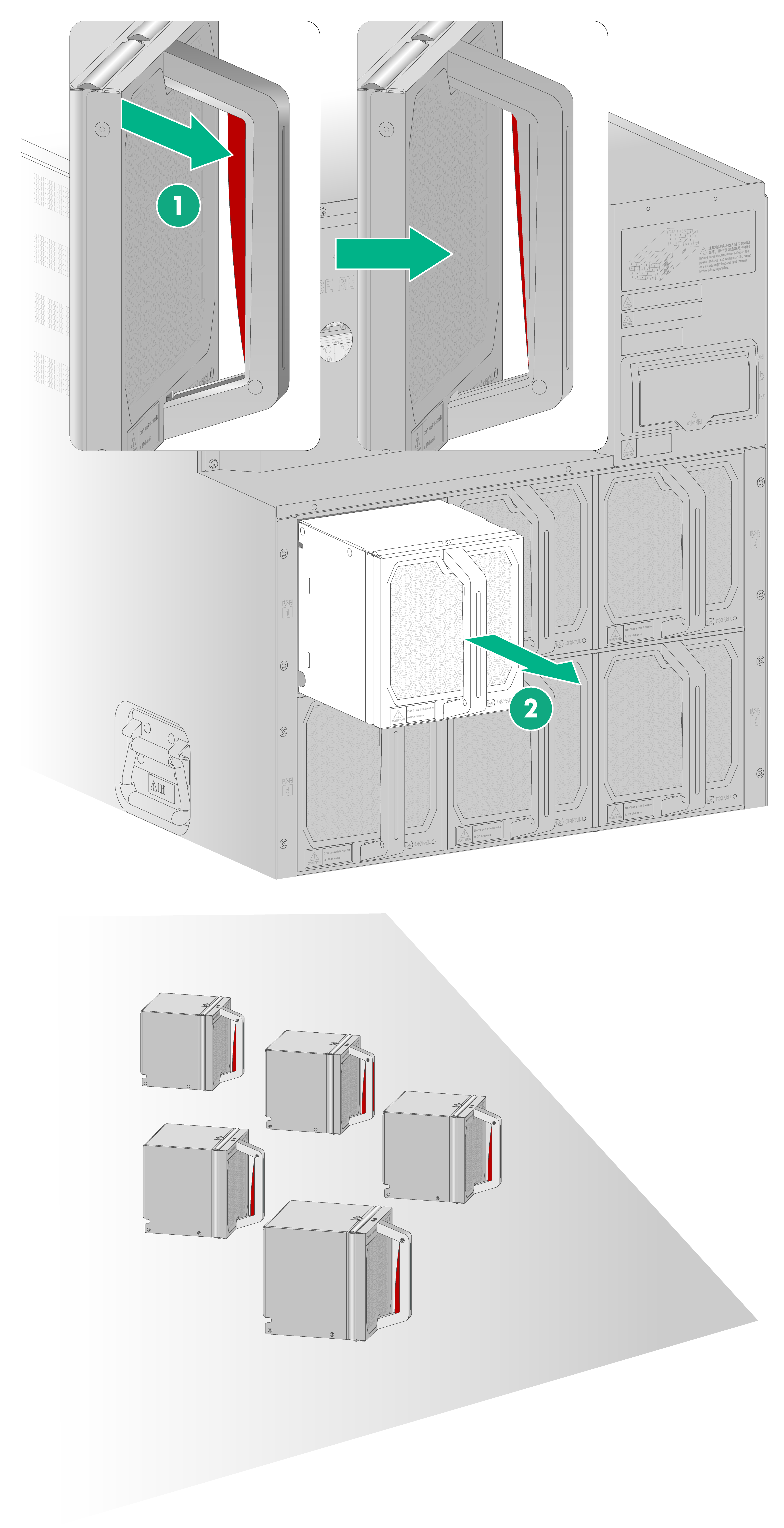
8. Remove all fan trays from the chassis.
To remove a fan tray, press the red button on the fan tray handle and then pull the fan tray out of the chassis slowly.
After removing a fan tray, place it upside down on an anti-static mat with the bottom clasp facing up, as shown in Figure 3-11.
Figure 3-11 Removing fan trays
9. Adjust the levelling foot of the dolly so that the dolly wheels support the chassis.
10. Move the chassis to the front of the rack and then detach the dolly from the chassis as follows:
a. Use a Phillips screwdriver to remove the screws on the wide side of the L-type brackets.
b. Use a wrench to remove the screws on the narrow side of the L-type brackets.
Figure 3-12 Detaching the dolly from the chassis
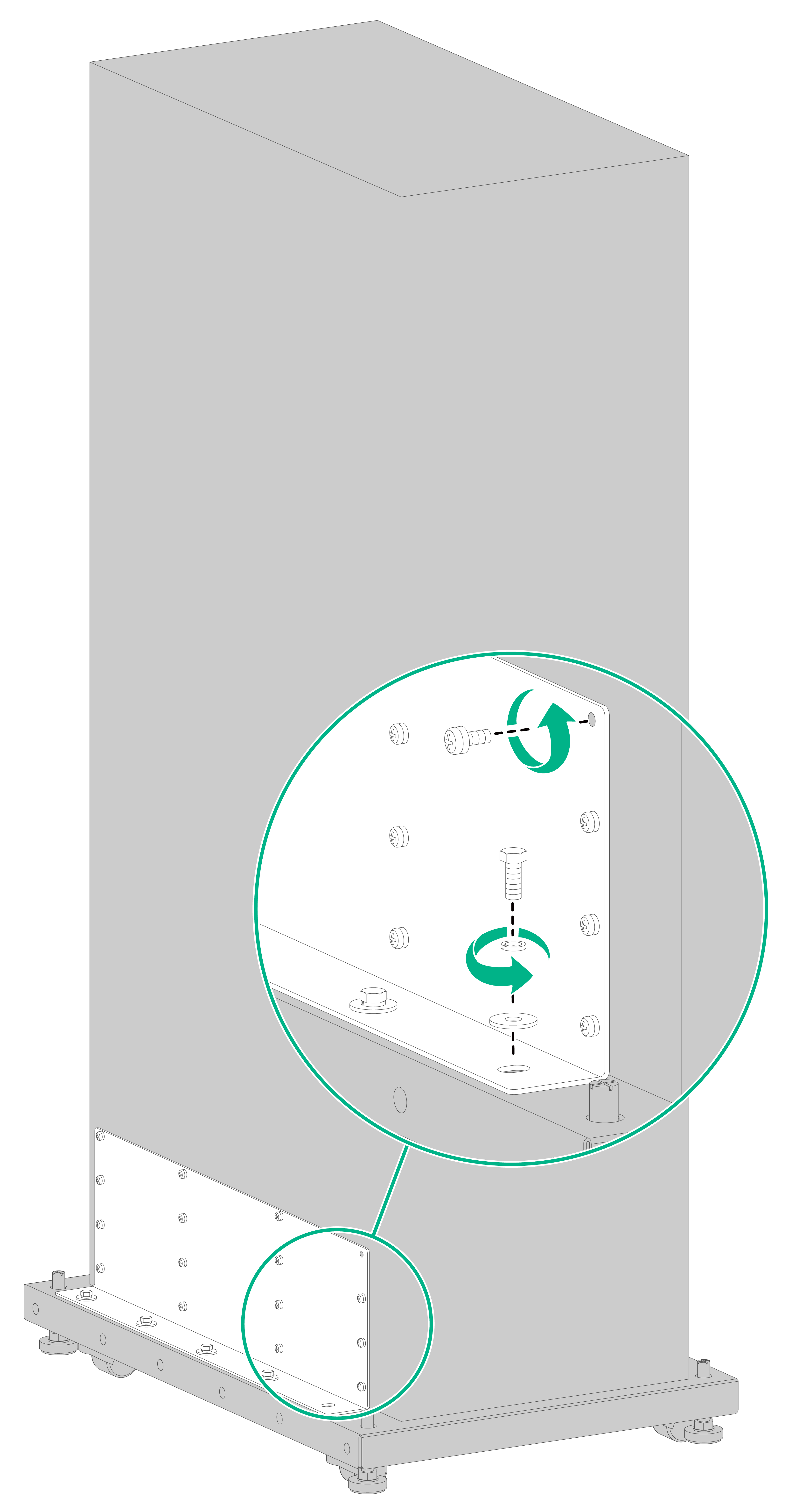
|
|
IMPORTANT: · The router is high and heavy. As a best practice, align the chassis with the rack and guide rails in the rack before detaching the dolly from the chassis. Ensure that the L-type brackets are removed completely before rack-mounting the router. · Keep the detached dolly secure for later use. |
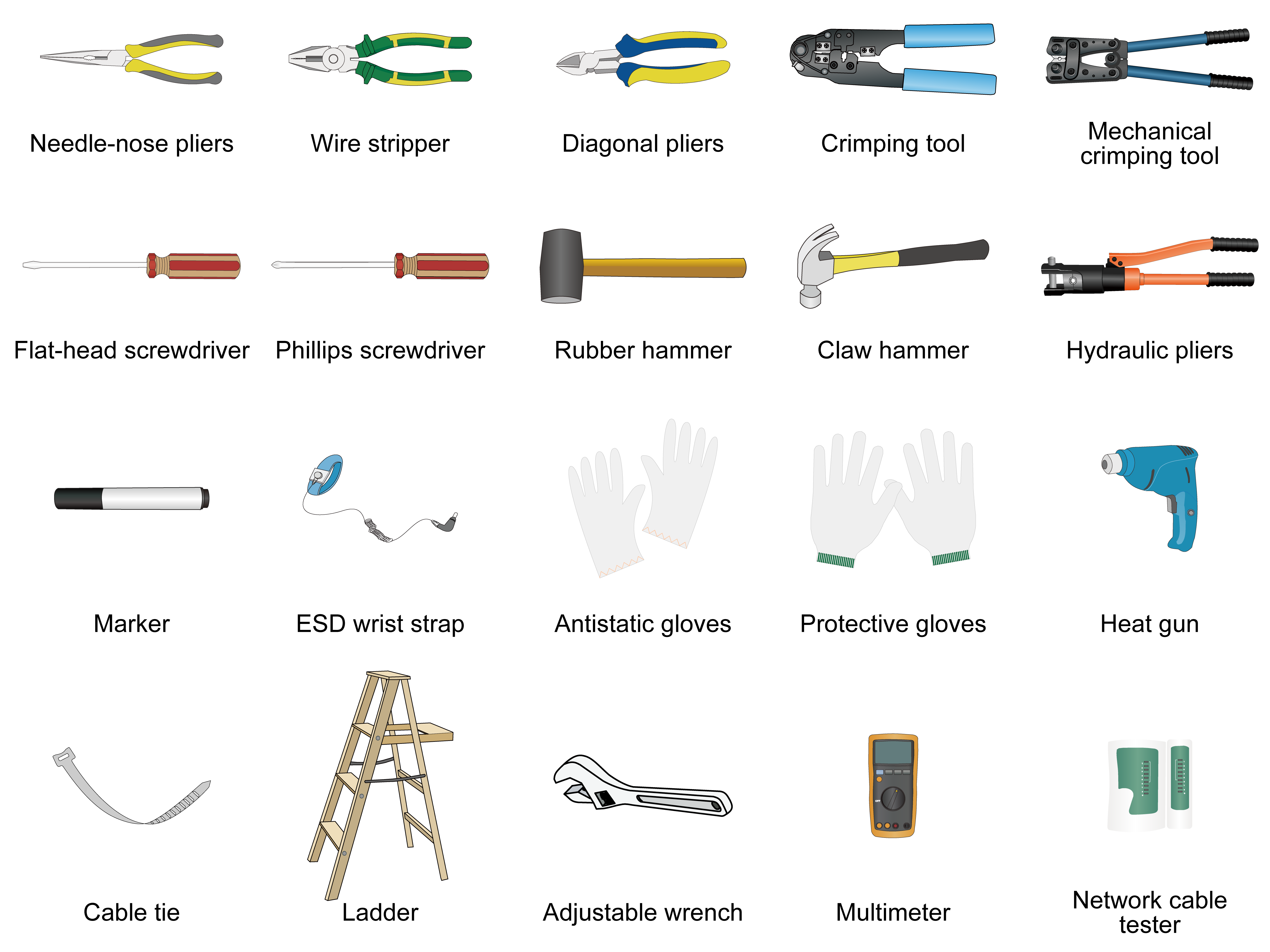
Installation tools
Installation tools are required when installing the router. Prepare installation tools as required. Figure 3-13 provides installation tools for your reference.
Figure 3-13 Installation tools
5 Installing the router
|
|
CAUTION: · The router is heavy. For rack stability, install the router at a lowest possible position on the rack. · Before rack-mounting the router, remove all the fan trays from it as a best practice to reduce the chassis weight. |
Attaching slide rails to the rack
|
|
CAUTION: · The router is high and heavy. To ensure rack and router stability, install slide rails at the location marked "1RU" on the rack. · Make sure the load-bearing plane of the slide rails installed on the rack is perpendicular to the four rack posts. |
To rack-mount the router, select and attach slide rails to the rack. See Table 5-1 for the slide rail requirements.
Table 5-1 Slide rail requirements
|
Max. chassis weight (fully configured) |
Applicable slide rails |
||
|
Slide rail model |
Adjustment range |
Occupied space |
|
|
600 kg (1322.75 lb) |
LSXM1BSR |
630 mm to 900 mm (24.80 in to 35.43 in) |
1 RU |
For information about installing the slide rails, see H3C LSXM1BSR 1U Bottom-Support Rails Installation Guide (available at https://www.h3c.com/en/Support/Resource_Center/EN/Routers/Catalog/CR19000/CR19000/).
(Optional) Installing PDUs
If you are to use PDUs, install PDUs on the rack before installing the router in the rack. Two PDU brackets are required for installing a PDU on the rack.
To install PDUs:
1. Determine the PDU bracket installation locations on the rack posts.
Make sure the PDU brackets do not cross the rack beam, do not affect fan tray installation, removal, and maintenance, and allow easy cable routing.
2. Install cage nuts at the PDU bracket installation locations, as shown by callout 1 in Figure 5-1.
3. Use two M6 screws to secure a PDU bracket to the rack post, as shown by callout 2 in Figure 5-2.
4. Attach the PDU to the PDU brackets. See callout 3 in Figure 5-2.
¡ To install the PDU on the right rack post, align the two left installation holes of the PDU with that in the PDU bracket and use screws to secure the PDU to the bracket. Then use the same method to secure the other end of the PDU to the rack.
¡ To install the PDU on the left rack post, align the two right installation holes of the PDU with that in the PDU bracket and use screws to secure the PDU to the bracket. Then use the same method to secure the other end of the PDU to the rack.
5. Repeat the above steps to install other PDUs.
Removing the top hood
The top hood of the router blocks the installation holes in the mounting brackets. Before mounting the router in the rack, remove the top hood from it.
To remove the top hood from the router:
1. Wear an ESD wrist strap. Make the wrist strap makes good skin contact and is reliably grounded.
2. Use a screwdriver to loosen the captive screws at the two sides of the top hood and then remove the top hood from the chassis.
Figure 5-2 Removing the top hood

Mounting the router in a rack
|
|
CAUTION: If condensation occurs on the chassis when you move it from a lower temperature to a higher temperature, dry the chassis before installing it to avoid short circuits. |
To mount the router in a rack:
1. Wear an ESD wrist strap and verify that the rack is sturdy and reliably grounded.
2. Determine and mark the cage nut installation holes on the front rack posts according to the mounting holes in the mounting brackets, as shown in Figure 4-1.
The mounting brackets are long and have been installed in the chassis. You can also use a tool, such as a tape measure, to measure and mark the cage nut installation holes on the front rack posts.
Figure 5-3 Marking the cage nut installation holes
3. Insert cage nuts into the marked square holes in the front rack posts.
Figure 5-4 Installing the cage nuts
4. Orient the chassis with the rear facing the front of the rack.
5. Use a minimum of four people to lift the router to a height slightly above the slide rails by holding the chassis handles. Then place the router on the slide rails.
|
|
CAUTION: After you place the router on the slide rails from front of the rack, do not leave go of your hands immediately because this might tip and damage the router. |
6. Arrange people in front of and behind the chassis working in cooperation to slide the router along the guide rails into the rack until the mounting brackets on the router are flush against the front rack posts.
The persons in front of the chassis push and a person behind the chassis pulls the chassis by holding the two horizontal handles in the fan tray area (as shown in Figure 5-5).
|
|
CAUTION: To avoid damaging the handles in the fan tray area, apply force only in the horizontal direction rather than vertical direction when using the handles to pull the chassis. |
Figure 5-5 Rear pulling of the router
7. Use M6 screws provided with the router to secure the router to the rack posts, as shown in Figure 5-6.
Figure 5-6 Securing the router to the rack
Installing fan trays
|
|
CAUTION: The router has 33 fan tray slots at the chassis rear, arranged in 11 rows with three fan tray slots in each row. To ensure adequate heat ventilation, install a fan tray in each fan tray slot. |
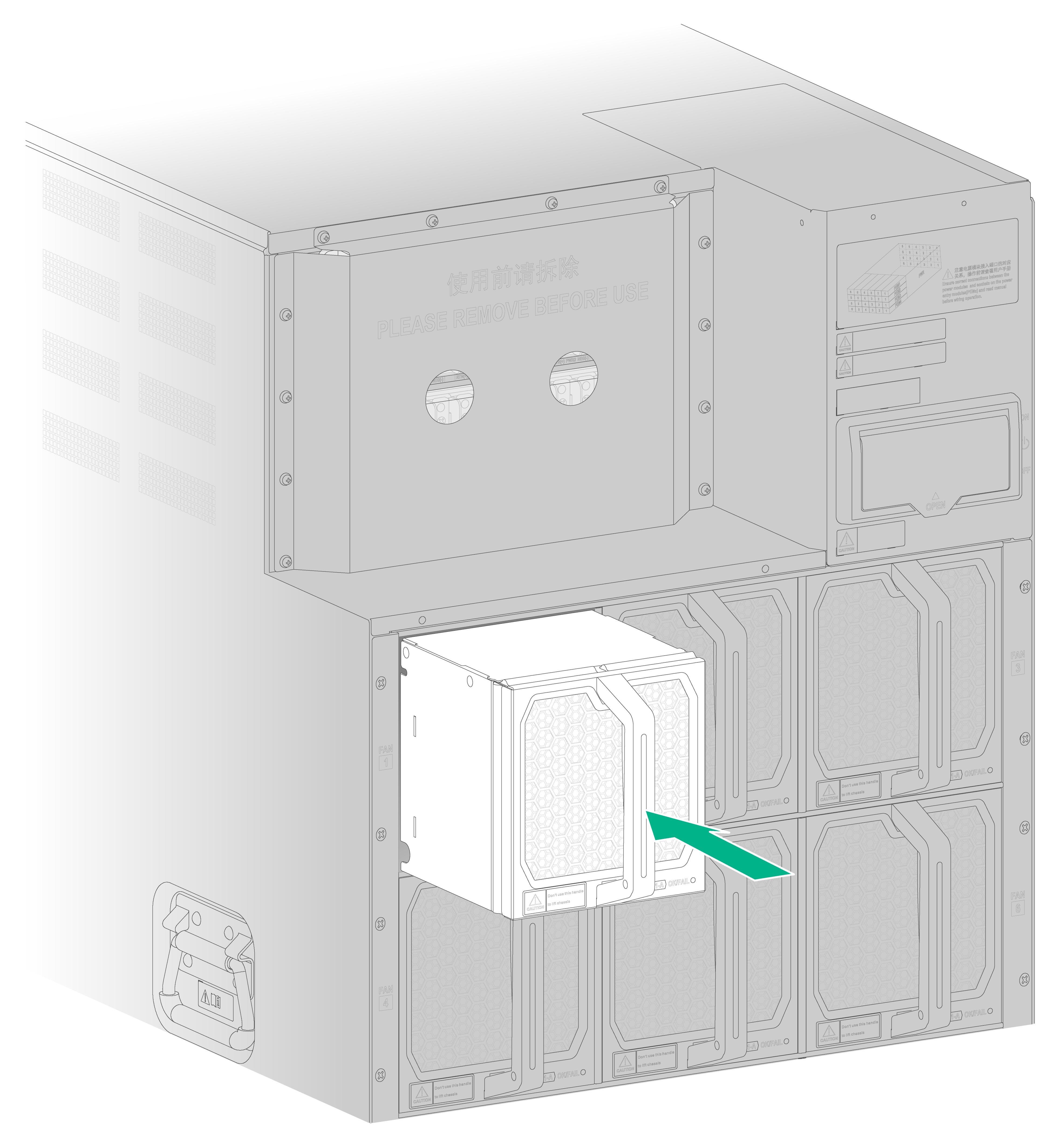
To install a fan tray:
1. Wear an ESD wrist strap.
2. Correctly orient the fan tray (with the lettering on it upward) and align the fan tray with the fan tray slot.
3. Grasp the handle of the fan tray with one hand and support its bottom with the other, and steadily insert the fan tray way into the slot.
Figure 5-7 Installing a fan tray
Grounding the router
|
|
CAUTION: Make sure the ground point on the rack is connected reliably to a grounding strip in the equipment room. |
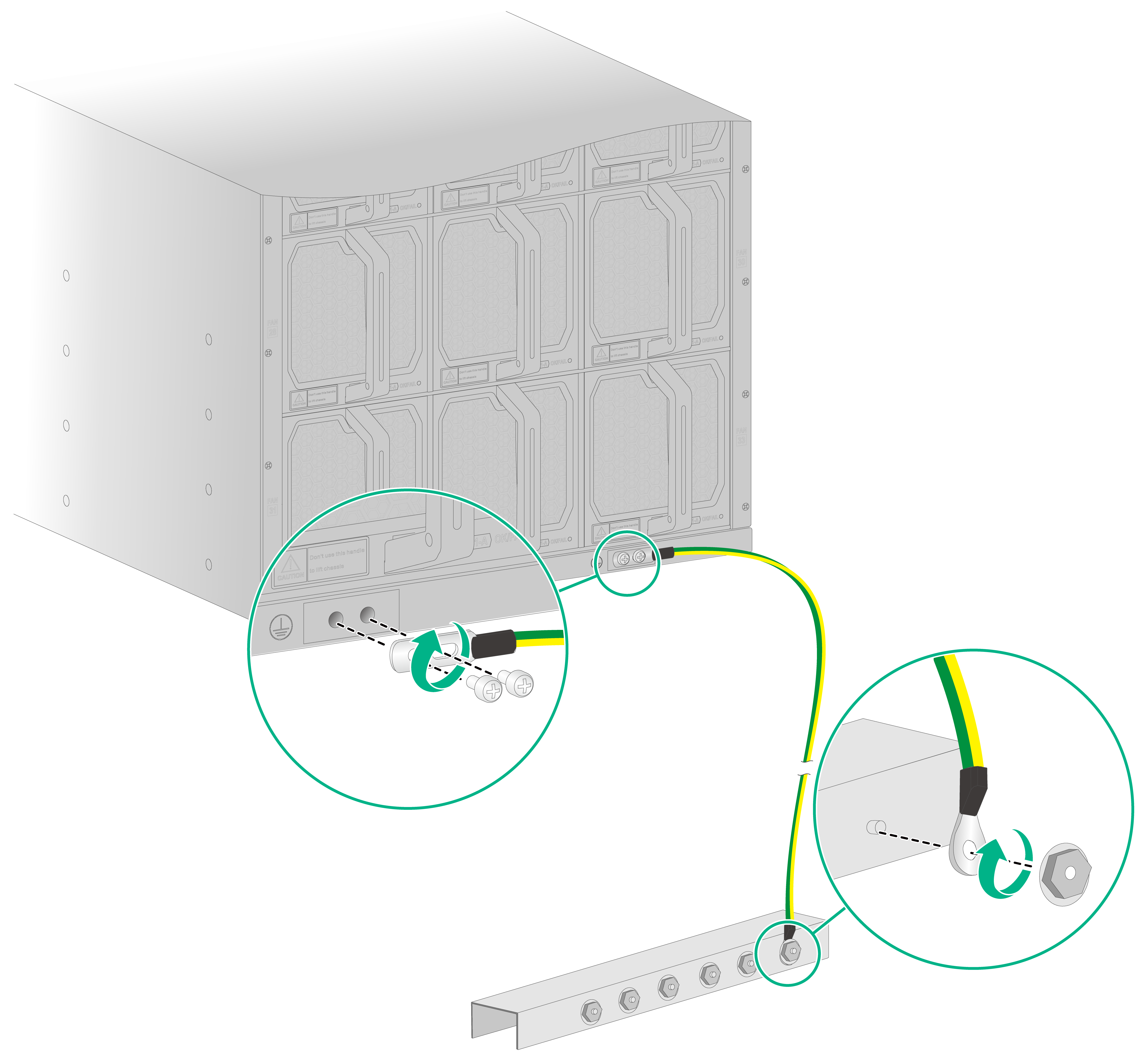
To ground the router:
1. Remove the grounding screws from the grounding point on the chassis.
2. Use the grounding screws to attach the two-hole grounding lug of the grounding cable to grounding point on the chassis.
3. Connect the ring terminal of the grounding cable to the grounding point on the rack.
Figure 5-8 Grounding the router
Installing cable management brackets
|
|
IMPORTANT: To prevent cable management brackets from blocking the mounting bracket mounting holes on the rack posts, install cable management brackets after you mount the router in the rack. |
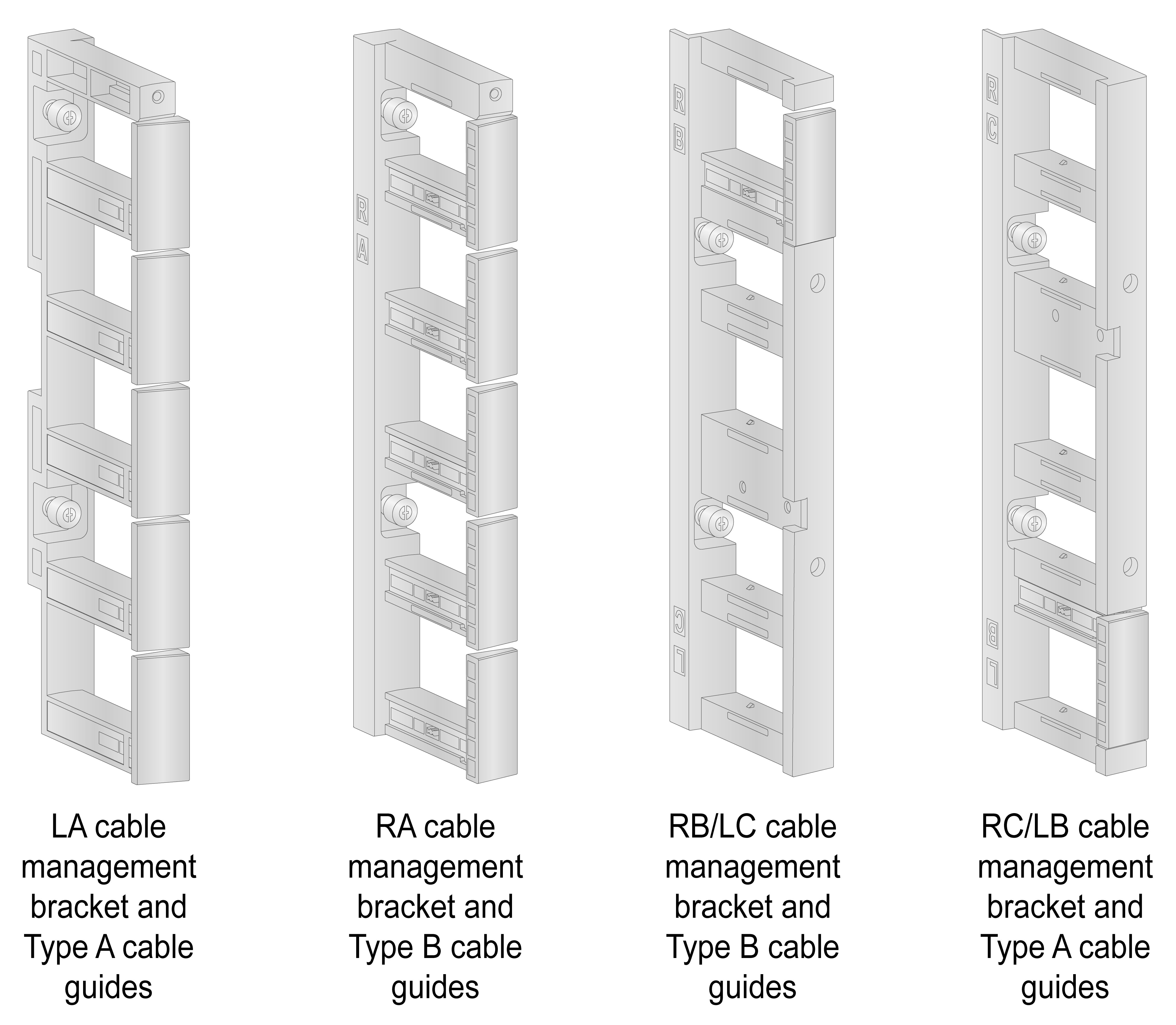
The router comes with four types of cable management brackets LA, RA, RB/LC, and RC/LB and two types of cable guides A and B. The cable management brackets come with cable guides installed.
Figure 5-9 Cable management brackets
The procedure is similar for installing cable management brackets at the left side and at the right side. The following installs a cable management bracket at the right side.
To install a cable management bracket:
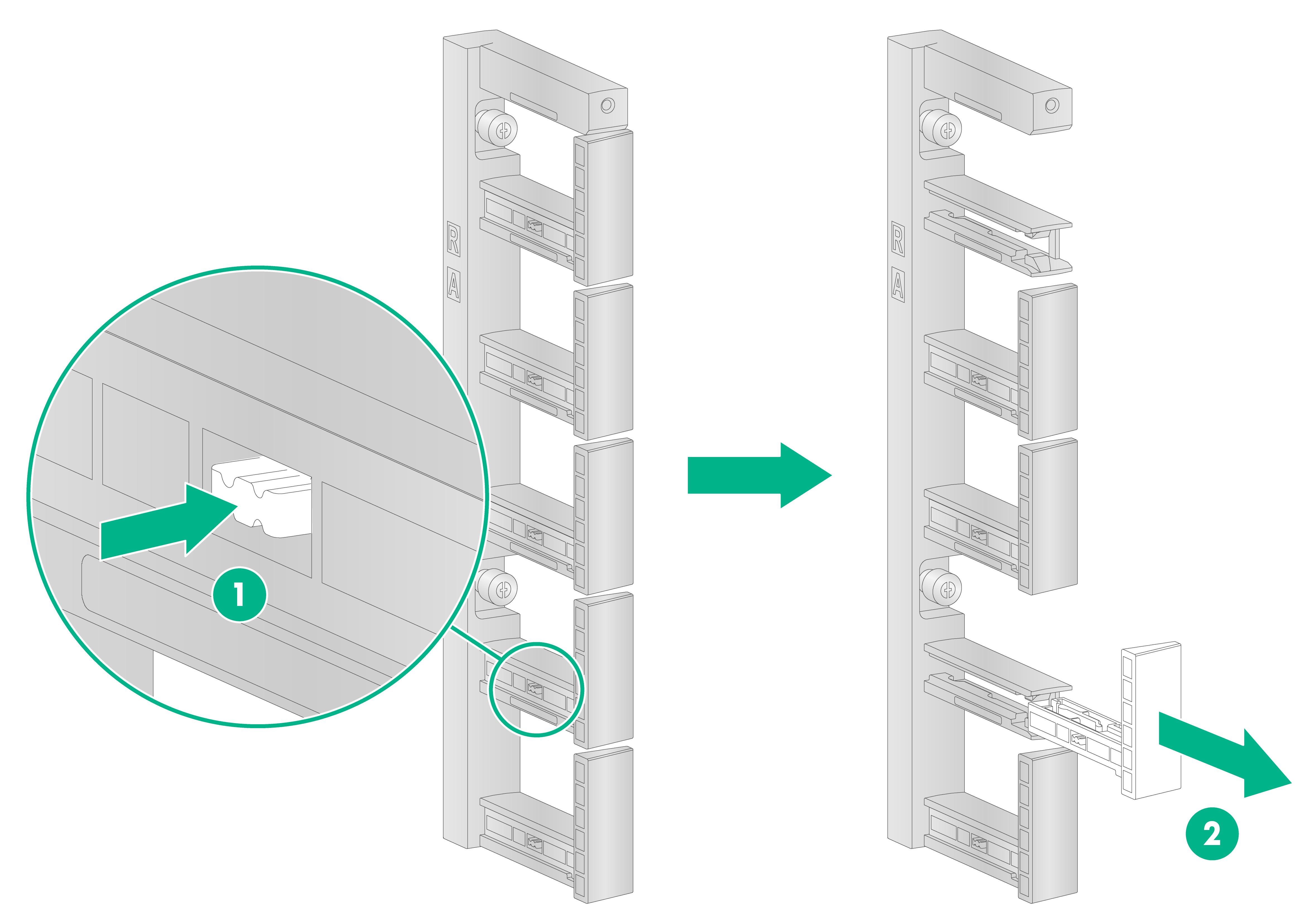
1. If any cable guide hinders installation of the cable management bracket, press the tab on the cable guide and then remove the cable guide from the cable management bracket.
Figure 5-10 Removing a cable guide
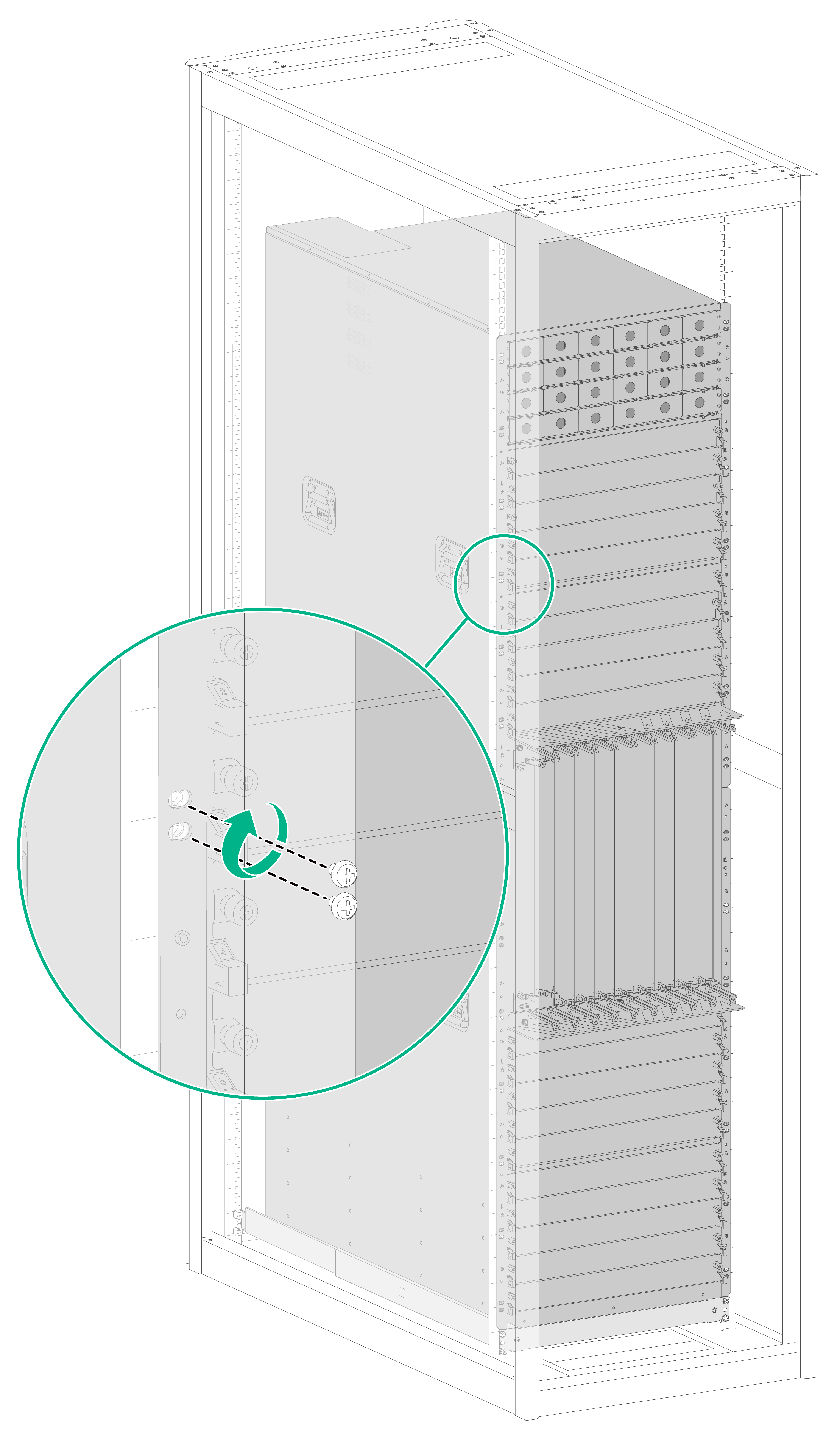
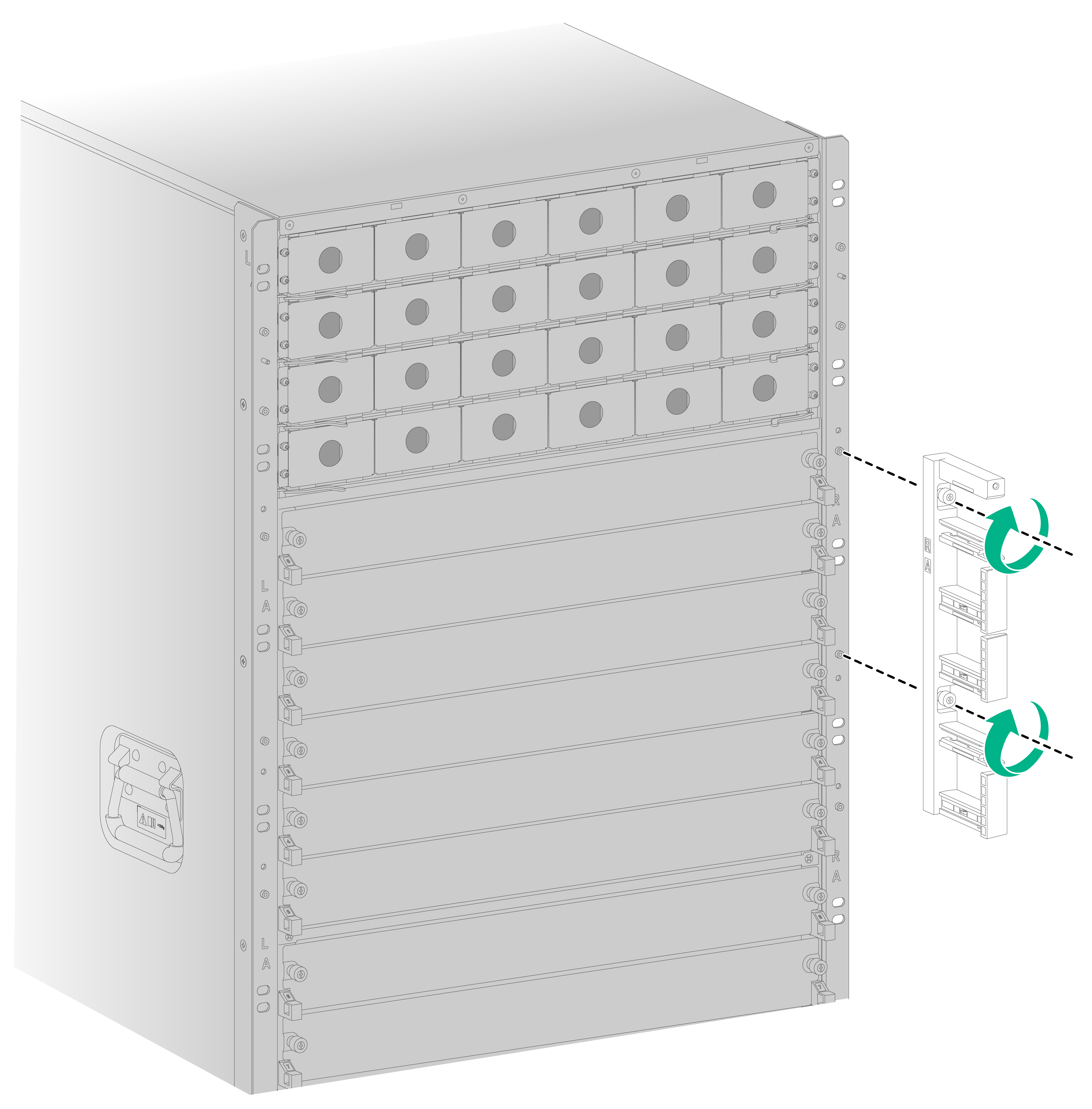
2. Identify the installation position on the mounting bracket. The LA, LB, LC, RA, RB, and RC marks on the mounting brackets indicate the types of cable management brackets to be installed.
3. Orient the cable management bracket, with the lettering facing upward, and then position the cable management bracket on the mounting bracket.
4. Align the captive screws on the cable management bracket with the holes in the mounting bracket. Fasten the captive screws to secure the cable management bracket.
Figure 5-11 Installing a cable management bracket
5. Install the removed cable guides (if any) on the cable management bracket.
6 Installing power supplies
The router supports DC, AC, and high-voltage DC (HVDC) power inputs. The power supply system of the router includes power trays (PEMs) and power supplies. The router supports four power trays and each power tray supports six power supplies. You can select power trays and power supplies as required.
Power trays and power supplies
|
|
CAUTION: Do not install power supplies of different models on the same router. |
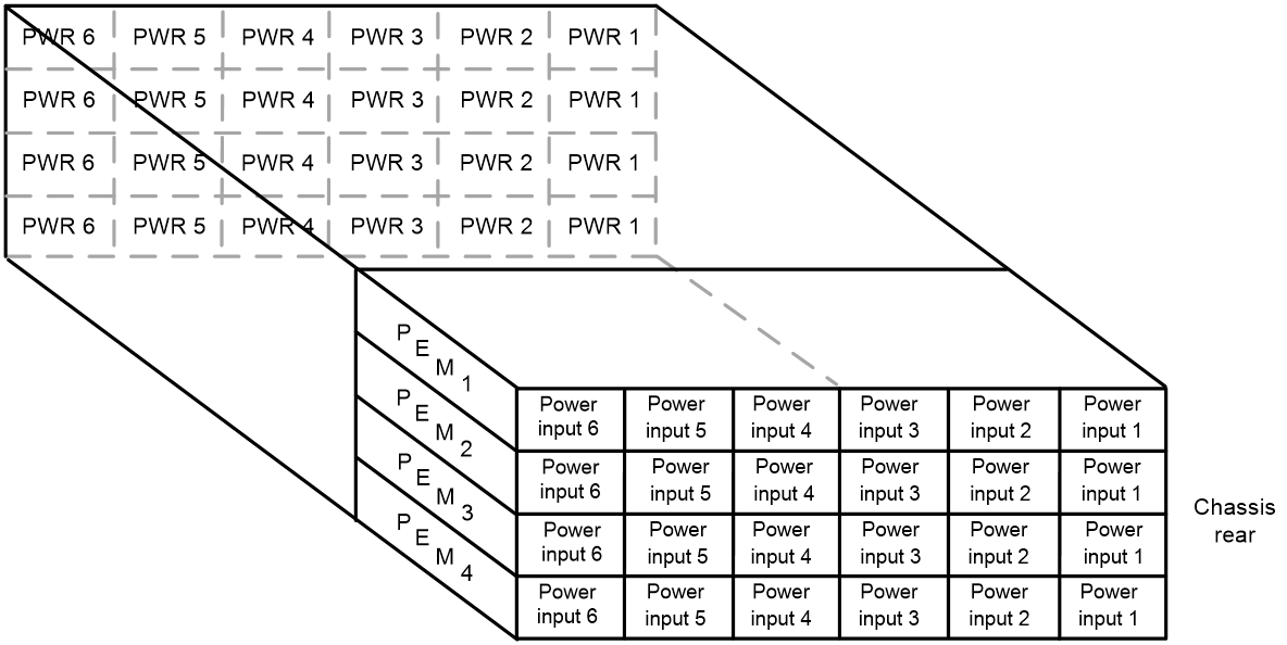
The power supplies are installed in the power trays. Power supplies at the front correspond to the power input ends at the rear as shown in Figure 6-1.
Figure 6-1 Power supplies and power input ends
Installing DC power supplies
Available DC power supplies
The PSR2000B-54D DC power supply is available for the router. Table 6-1 describes the PSR2000B-54D DC power supply specifications.
Table 6-1 PSR2000B-54D DC power supply specifications
|
Item |
Specification |
|
Rated input voltage |
–48 to –60 VDC |
|
Input voltage range |
–39 to –72 VDC |
|
Max. input current |
60 A |
|
Rated output voltage |
54 VDC |
|
Max. output current |
37 A |
|
Max. output power |
2000 W |
|
Compatible power tray model |
CR-PEM-DC2000 |
DC power supply configuration guidelines
Determine the number of DC power supplies based on the system power consumption and the DC power supply configuration based on the power input mode.
· As a best practice, configure N+M (M ≥ 1) DC power supply redundancy. Make sure N+M is not larger than the total number of power supply slots.
N is the number of DC power supplies.
· Make sure the total output power of the power supplies is greater than the system power consumption (with a 20% power surplus as a best practice).
· Provide a circuit breaker or fuse for power input of each DC power supply. Make sure each input line has a current carrying capacity not less than 60 A.
Installing a DC power supply
|
|
IMPORTANT: To use fewer than 24 power supplies on the router, install them from the right slots to facilitate power cord wiring and power supply expansion. |
To install a DC power supply:
1. Wear an ESD wrist strap. Make sure the strap makes good skin contact and is reliably grounded.
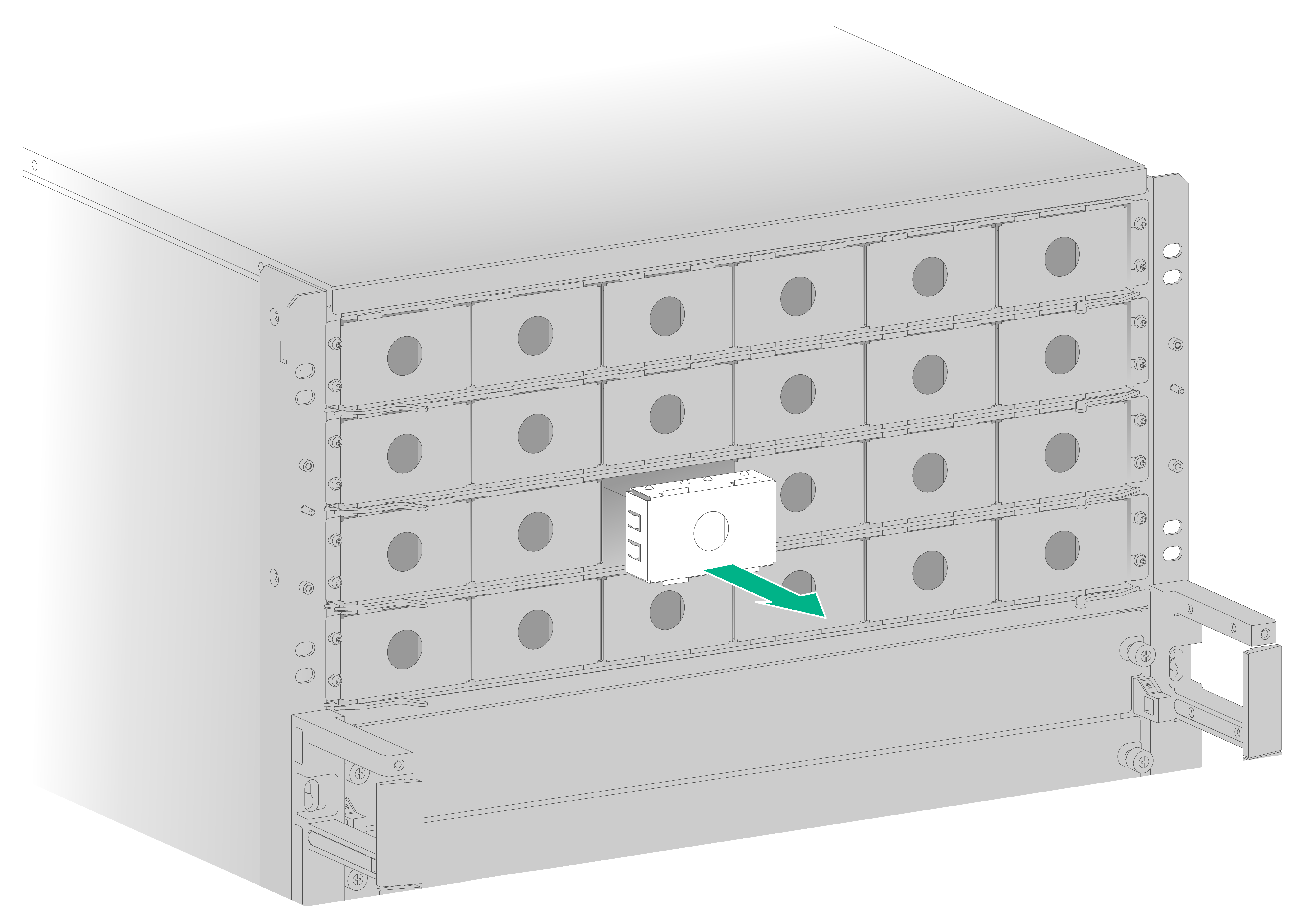
2. Remove the filler panel from the target power supply slot.
Put your forefinger into the hole of the filler panel to hold and pull out the filler panel along the guide rails, as shown in Figure 6-2.
Figure 6-2 Removing a filler panel
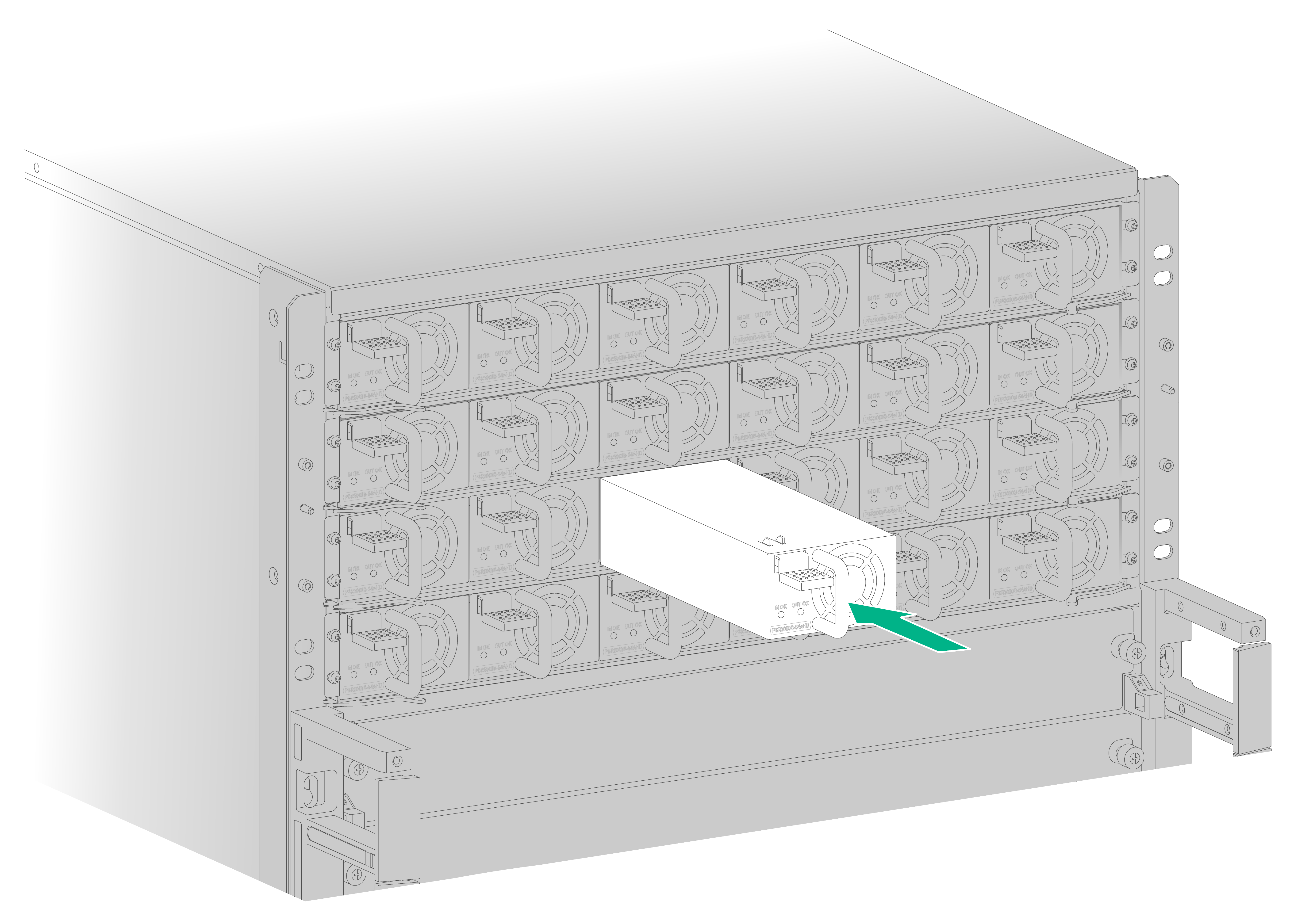
3. Correctly orient the power supply.
4. Align the power supply with the power supply slot. Then slide the power supply along the guide rails into the slot until the latch locks the power supply in place.
Figure 6-3 Installing a DC power supply

Connecting a DC power cord
|
|
WARNING! · Before you connect a power cord, turn off the circuit breaker for it and turn off the two switches on the router. · Make sure each power cord has a separate circuit breaker. · Each CR-PEM-DC2000 power tray has a cover at the rear to protect the operators from electric shock. Before you connect a power cord, remove the cover. Reinstall the cover after connecting the power cord. |
To make DC power wires by using dual-hole terminal lugs yourself, see DC power cord connection in H3C CR19000-20 Core Router Installation Guide.
To connect a DC power cord:
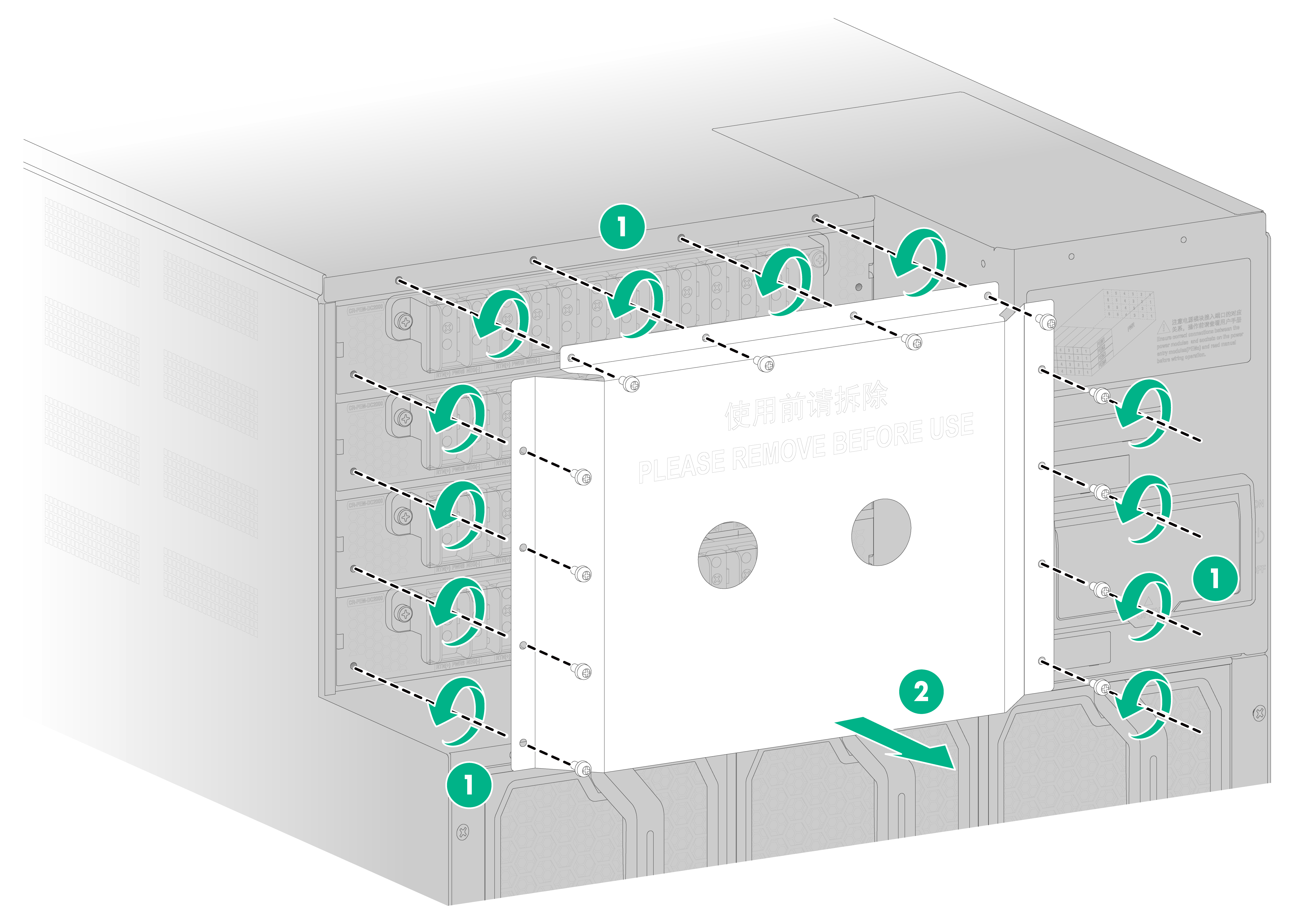
1. Remove the protective plate over the power input area, as shown in Figure 6-4.
Figure 6-4 Removing the protective plate
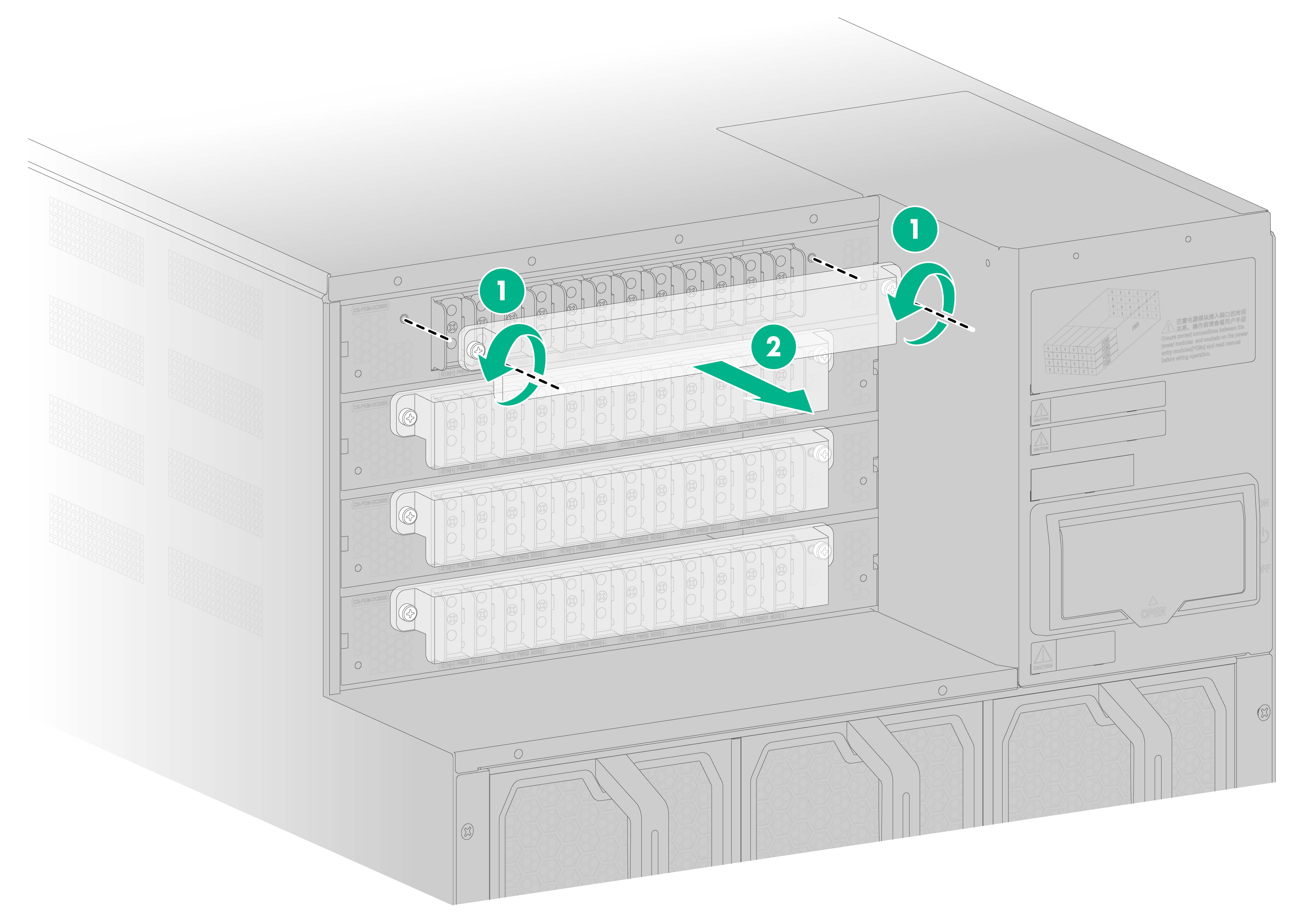
2. Remove the cover on the power tray, as shown in Figure 6-5.
Keep the removed cover secure and reinstall it after connecting the power cord.
Figure 6-5 Removing the cover from the power tray
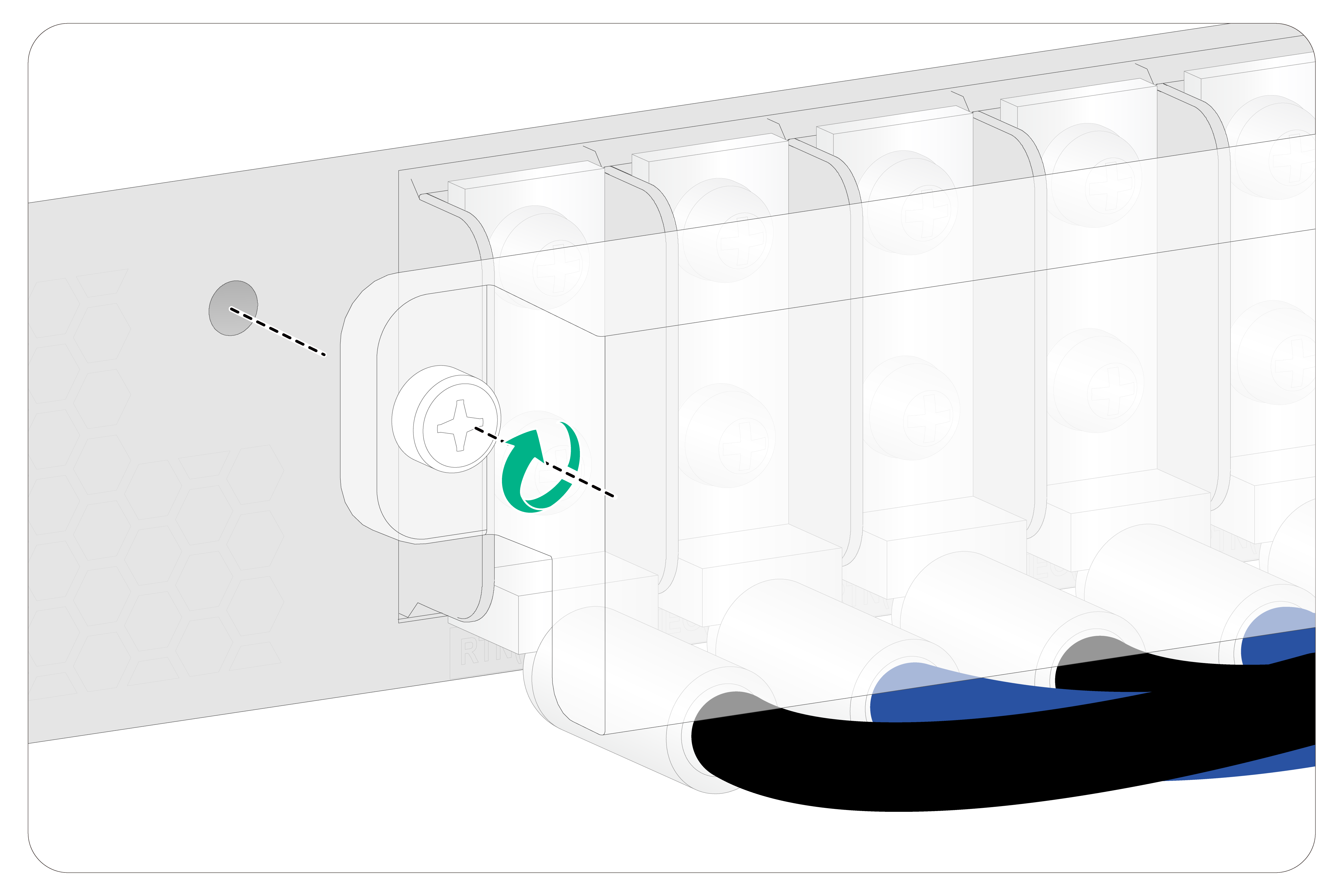
3. Remove the screws on the terminal blocks.
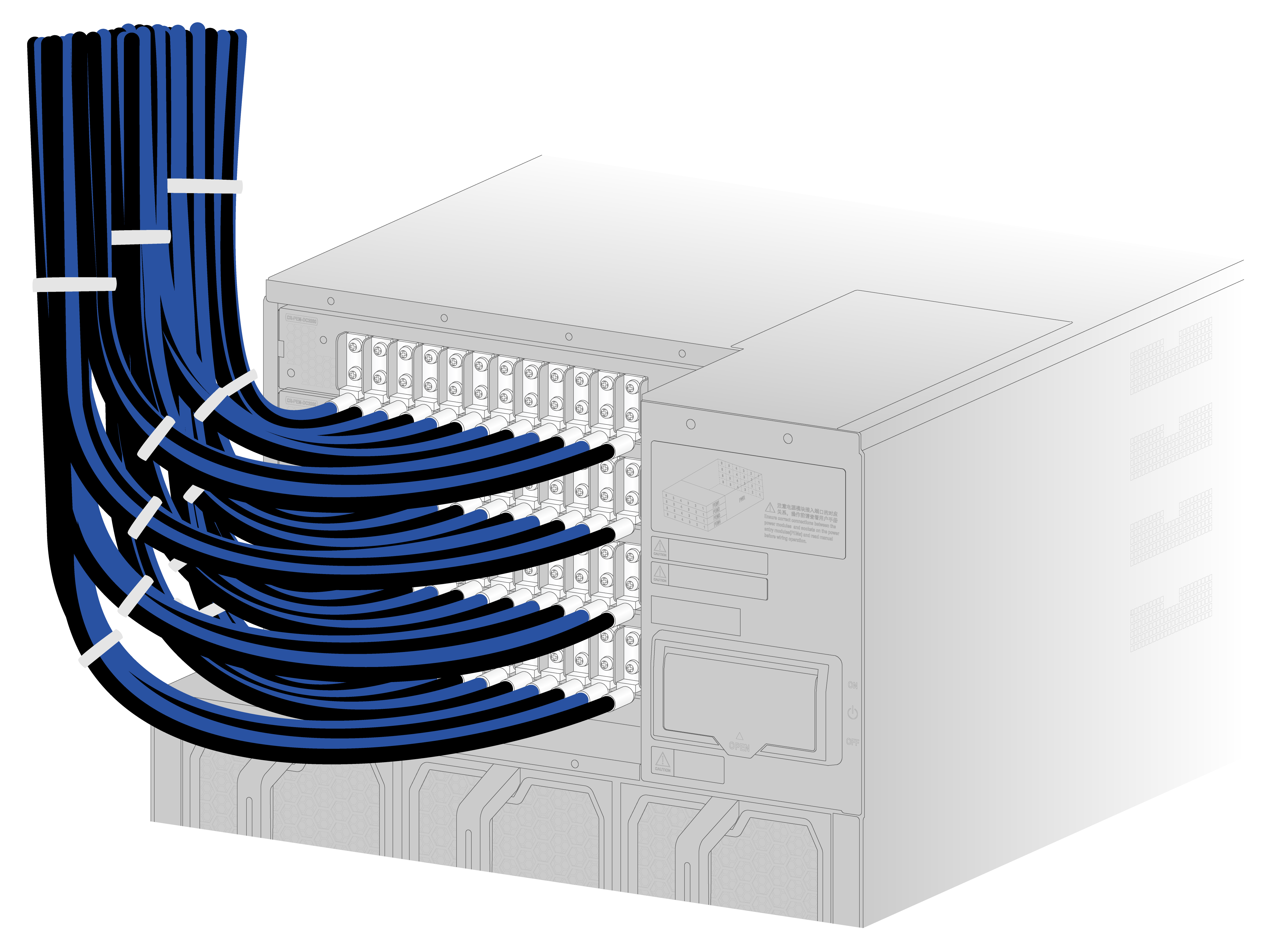
4. Use the screws to connect the black wires to the positive terminals marked with RTN(+) and the blue wires to the negative terminals marked with NEG(–), as shown in Figure 6-6.
For multiple DC power cords, connect them to the terminal blocks from left to right, as shown in Figure 6-7, Figure 6-8, and Figure 6-9.
Figure 6-6 Connecting DC power cords to the DC terminal blocks
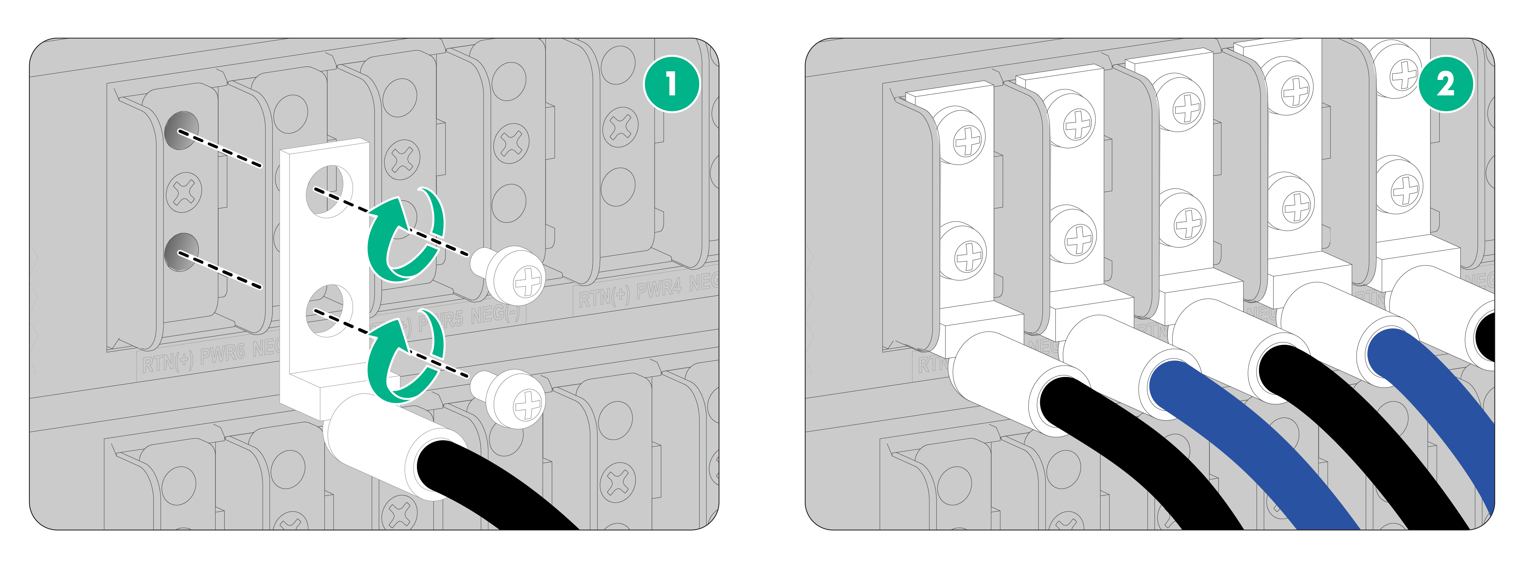
Figure 6-7 Connecting power cords to the terminal blocks from left to right (1)
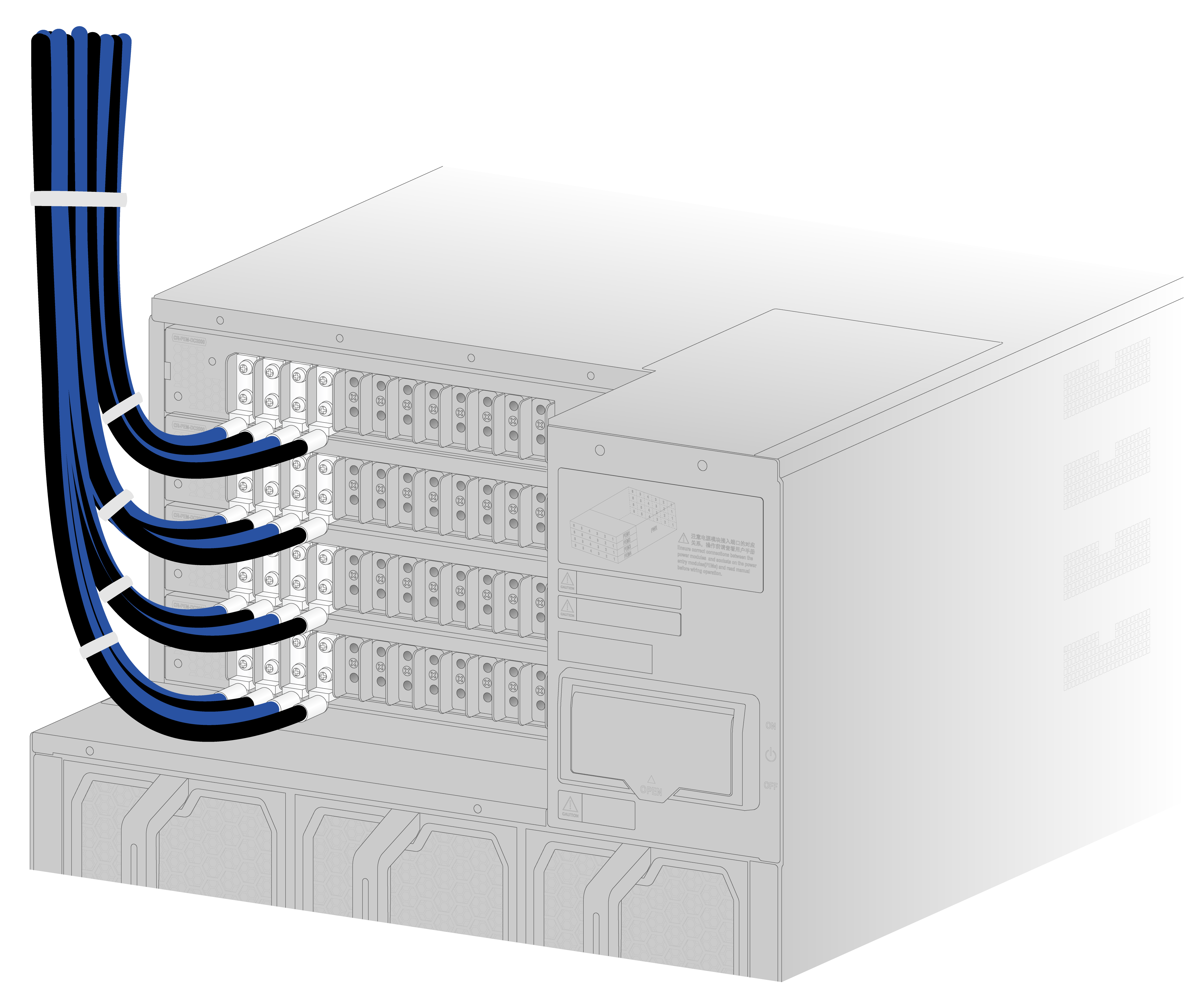
Figure 6-8 Connecting power cords to the terminal block from left to right (2)
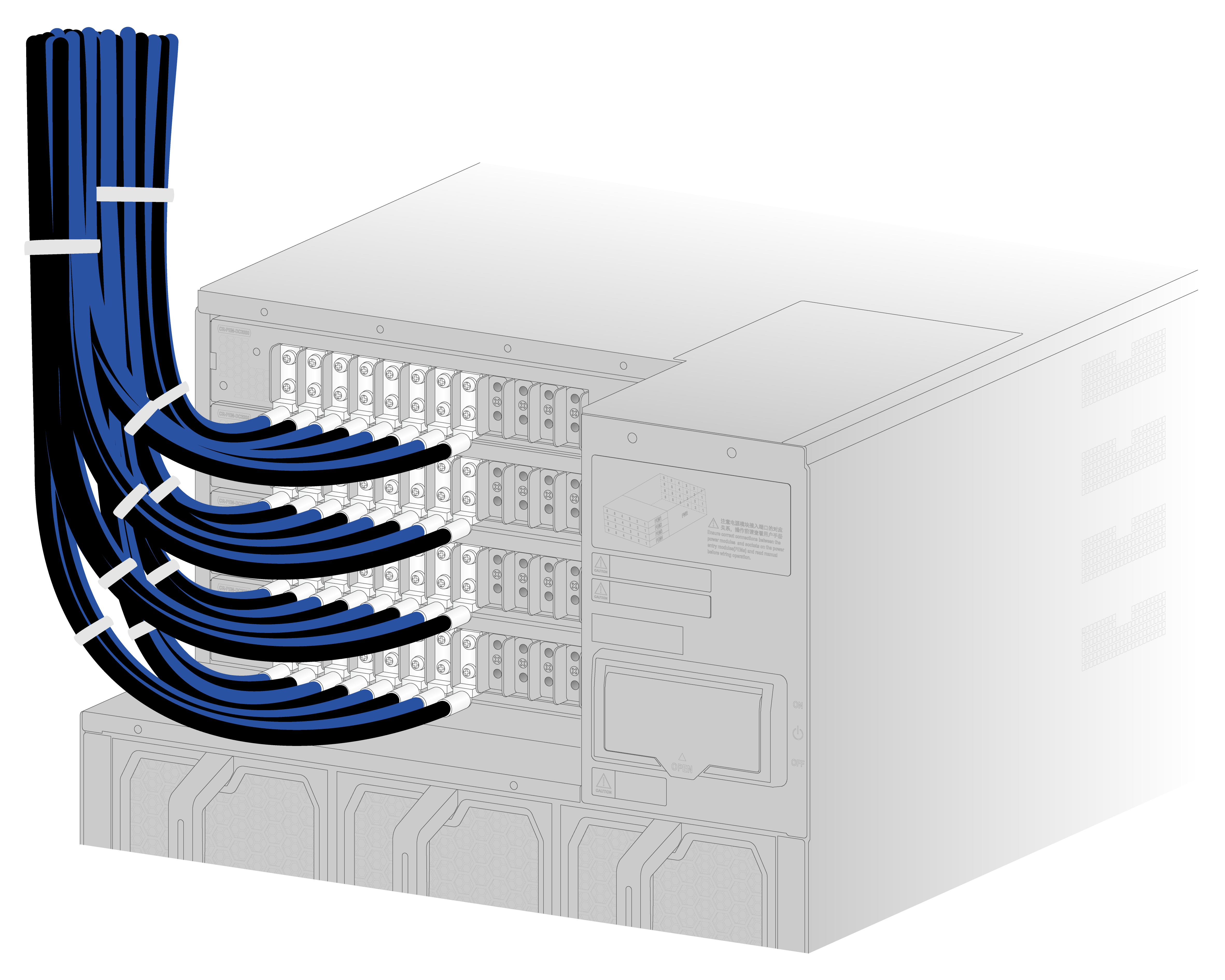
Figure 6-9 Connecting power cords to the terminal blocks from left to right (3)
5. Connect the other end of the power cord to a DC power source.
Connect the blue wires to the negative terminals marked with –48V and the black wires to the positive terminals marked with RTN(+).
6. Reinstall the cover on the power tray and then fasten the captive screws.
Figure 6-10 Reinstalling the cover on the power tray
7. Reinstall the protective plate over the power input area.
Installing AC power supplies
Available AC power supplies
The PSR3000B-54AHD power supply is available for the router. Table 6-2 describes the PSR3000B-54AHD power supply specifications.
Table 6-2 PSR3000B-54AHD power supply specifications
|
Item |
Specification |
|
Rated input voltage |
· 100 to 130 VAC @ 60 Hz · 200 to 240 VAC @ 50 Hz · 240 VDC · 336 VDC |
|
Input voltage range |
· 90 to 150 VAC @ 47 to 63 Hz · 176 to 290 VAC @ 47 to 63 Hz · 180 to 290 VDC · 260 to 400 VDC |
|
Rated input current |
16 A |
|
Rated output voltage |
54 VDC |
|
Max. output current |
55.6 A |
|
Max. output power |
· 100 to 130 VAC @ 60 Hz: 1500 W · 200 to 240 VAC @ 50 Hz: 3000 W · 240 VDC: 3000 W · 336 VDC: 3000 W |
|
Compatible power tray model |
· AC power input: CR-PEM-AC3000 and CR-PEM-HVDC3000 · 240 VDC power input: CR-PEM-AC3000 and CR-PEM-HVDC3000 · 336 VDC power input: CR-PEM-HVDC3000 |
AC power supply configuration guidelines
Determine the number of AC power supplies based on the system power consumption and the AC power supply configuration based on the power input mode.
· As a best practice, configure N+N (dual power sources) AC power supply redundancy. Make sure N+N is not larger than the total number of power supply slots.
N is the number of AC power supplies.
· Make sure the total output power of the power supplies is greater than the system power consumption (with a 20% power surplus as a best practice).
· Provide a circuit breaker for power input of each AC power supply. Make sure each circuit breaker has a current rating not less than 20 A.
Installing an AC power supply
|
|
IMPORTANT: To use fewer than 24 power supplies on the router, install them from the right slots to facilitate power cord wiring and power supply expansion. |
To install an AC power supply:
1. Wear an ESD wrist strap. Make sure the strap makes good skin contact and is reliably grounded.
2. Put your forefinger into the hole of the filler panel and to hold and pull out the filler panel along the guide rails as shown in Figure 6-11.
Figure 6-11 Removing a filler panel

3. Correctly orient the power supply.
4. Align the power supply with the power supply slot. Then slide the power supply along the guide rails into the slot until the latch locks the power supply in place.
Figure 6-12 Installing an AC power supply
Connecting an AC power cord
|
|
WARNING! Before you connect a power cord, turn off the switch at the power input end and two switches on the router. |
|
|
CAUTION: After connecting the power cord connector to the power tray, use the cable clamp provided with the router to secure the power cord to the AC input receptacle on the power tray. |
To connect an AC power cord:
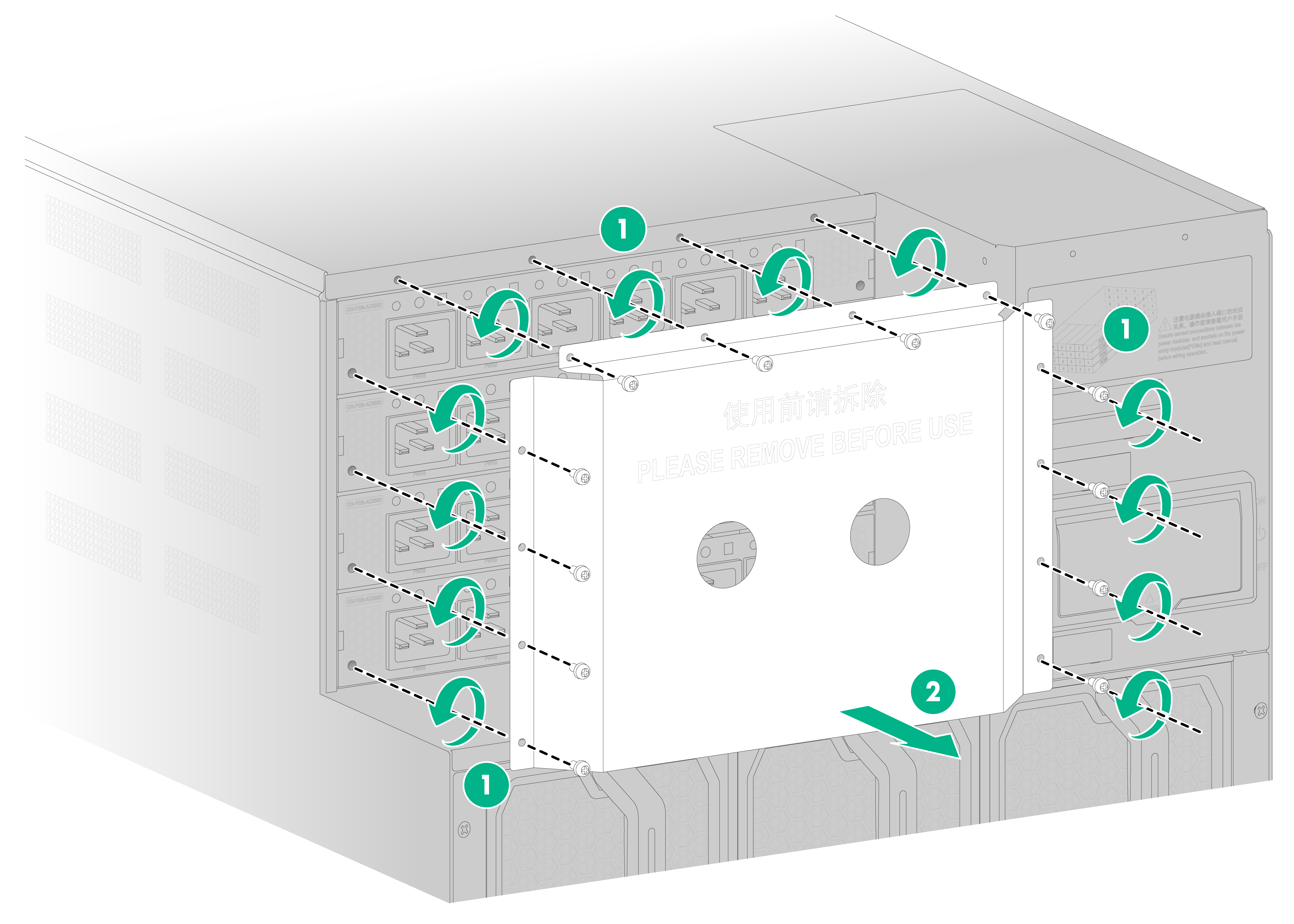
1. Remove the protective plate over the power input area, as shown in Figure 6-13.
Figure 6-13 Removing the protective plate
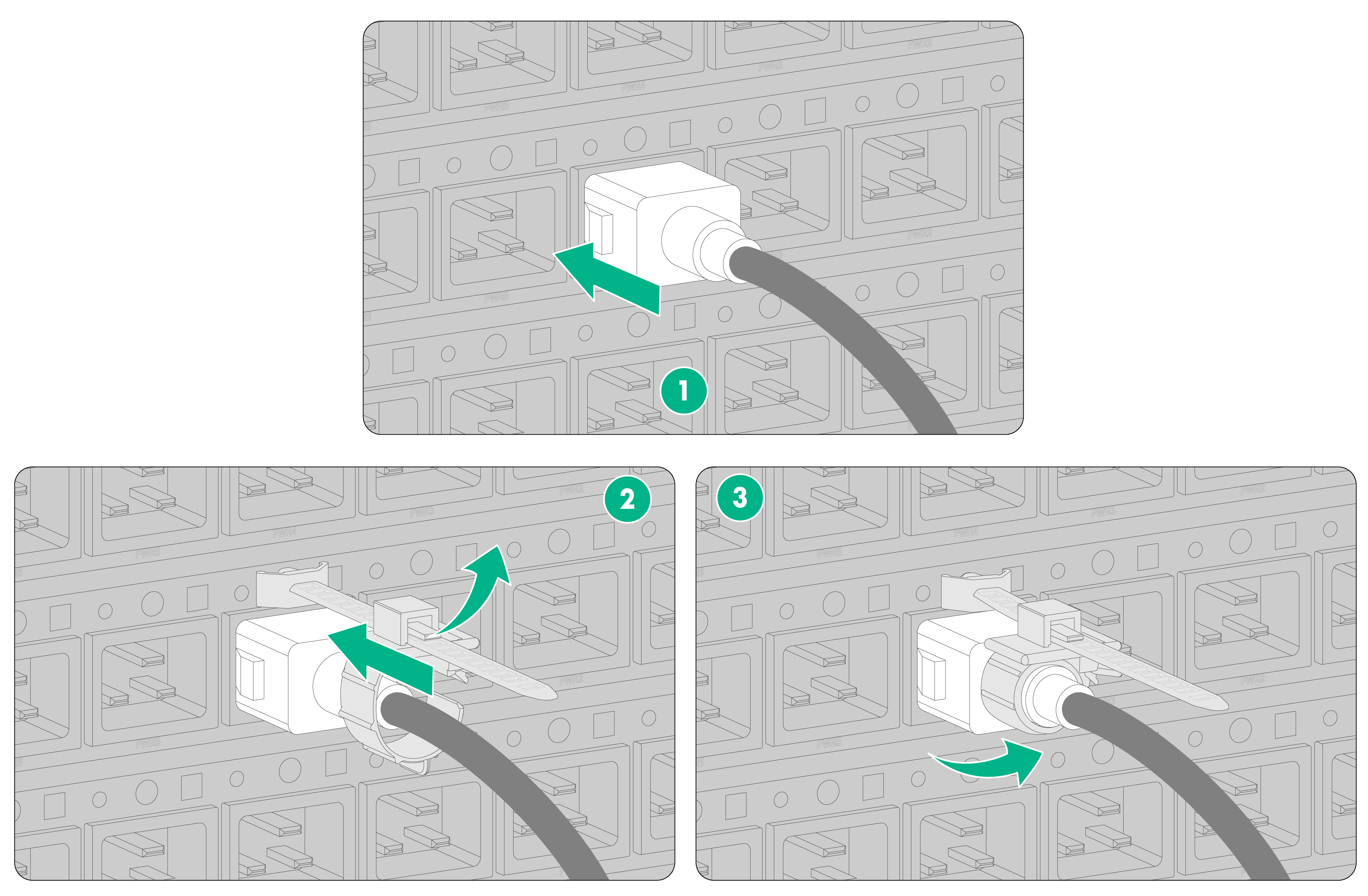
2. Connect the AC power cord connector to the AC input receptacle on the power tray, as shown by callout 1 in Figure 6-14.
3. Attach a cable clamp to the power tray. Release the tab on the tie mount and then slide the cable clamp forward until it is flush against the edge of the connector, as shown by callout 2 in Figure 6-14.
4. Close the cable clamp, as shown by callout 3 in Figure 6-14.
Figure 6-14 Connecting an AC power cord
5. Connect the other end of the AC power cord to an AC power source.
Installing HVDC power supplies
Available HVDC power supplies
The PSR3000B-54AHD power supply supports AC input and HVDC input and is available for the router for HVDC power input. See Table 6-2 for the PSR3000B-54AHD power supply specifications.
HVDC power supply configuration guidelines
Determine the number of HVDC power supplies based on the system power consumption and the HVDC power supply configuration based on the power input mode.
· As a best practice, configure N+N (dual power sources) HVDC power supply redundancy. Make sure N+N is not larger than the total number of power supply slots.
N is the number of HVDC power supplies.
· Make sure the total output power of the power supplies is greater than the system power consumption (with a 20% power surplus as a best practice).
· Provide a circuit breaker for power input of each HVDC power supply. Make sure each circuit breaker has a current rating not less than 20 A and meets the requirements for HVDC power supply, such as HVDC certification and bipolar protection.
Installing an HVDC power supply
For information about installing a PSR3000B-54AHD power supply, see "Installing an AC power supply."
Connecting an HVDC power cord
For information about connecting the power cord for a PSR3000B-54AHD power supply, see "Connecting an AC power cord."
7 Installing removable components
Installing MPUs
|
|
CAUTION: · Slots 20 and 21 are MPU slots. Keep the filler panel in the MPU slot if you are not to install an MPU in it. · The router supports active/standby MPU switchover. For the standby MPU to start up correctly, make sure the active and standby MPUs are the same model. |
To install an MPU:
1. Wear an ESD wrist strap and make sure it makes good skin contact and is reliably grounded.
2. Remove the filler panel from the target MPU slot.
Keep the removed filler panel secure for future use.
Figure 7-1 Removing a filler panel

3. Orient the MPU correctly and align the MPU with the slot. Insert the MPU into the slot and fully open the ejector levers on the MPU.
4. Continue to push the MPU by its middle part on the front panel until the brakes on its ejector levers touch the slot edges tightly.
5. Close the ejector levers until they come in close contact with the front panel.
6. Use a screwdriver to fasten the captive screws on the MPU.
Installing fabric modules
|
|
CAUTION: · The router provides eight fabric module slots at the rear. To use the following interface modules, you must install the fabric modules in slots 22 to 27. Installing fabric modules in slots 28 and 29 will not improve interface module performance. ¡ CR-19K-LPU-2002 ¡ CR-19K-LPU-2002B ¡ CR-19K-LPU-4004 ¡ CR-19K-LPU-8004 ¡ CR-19K-LPU-CC04 ¡ CR-19K-LPU-CC04B ¡ CR-19K-LPU-CC08 ¡ CR-19K-LPU-CQ06B ¡ CR-19K-LPU-CQ12 ¡ CR-19K-LPU-CQ12B ¡ CR-19K-LPU-CQ18 ¡ CR-19K-LPU-SP ¡ CR-19K-LPU-XP20CC02 ¡ CR-19K-LPU-XP40 ¡ CR-19K-LPU-XP48 ¡ CR-19K-LPU-XP72 · Keep the filler panel in the fabric module slot if you are not to install a fabric module in it. |
To install a fabric module:
1. Wear an ESD wrist strap and make sure it makes good skin contact and is reliably grounded.
2. Remove the filler panel from the target fabric module slot.
Keep the removed filler panel secure for future use.
3. (Optional.) For a multi-chassis fabric module, remove the protection cover from its front panel, as shown in Figure 7-3.
Figure 7-3 Removing the protection cover
4. Correctly orient the fabric module and align the fabric module with the slot. Insert the fabric module steadily into the slot and fully open the ejector levers of the fabric module, as shown in Figure 7-4.
Figure 7-4 Installing a fabric module
5. Continue to push the fabric module by its middle part on the front panel until the brakes on its ejector levers touch the slot edges tightly.
6. Close the ejector levers until they come in close contact with the front panel.
7. Use a Phillips screwdriver to fasten the captive screws on the fabric module.
Installing interface modules
|
|
CAUTION: Keep the filler panel in the interface module slot if you are not to install an interface module in it. |
Installing an interface module that uses detachable ejector levers
|
|
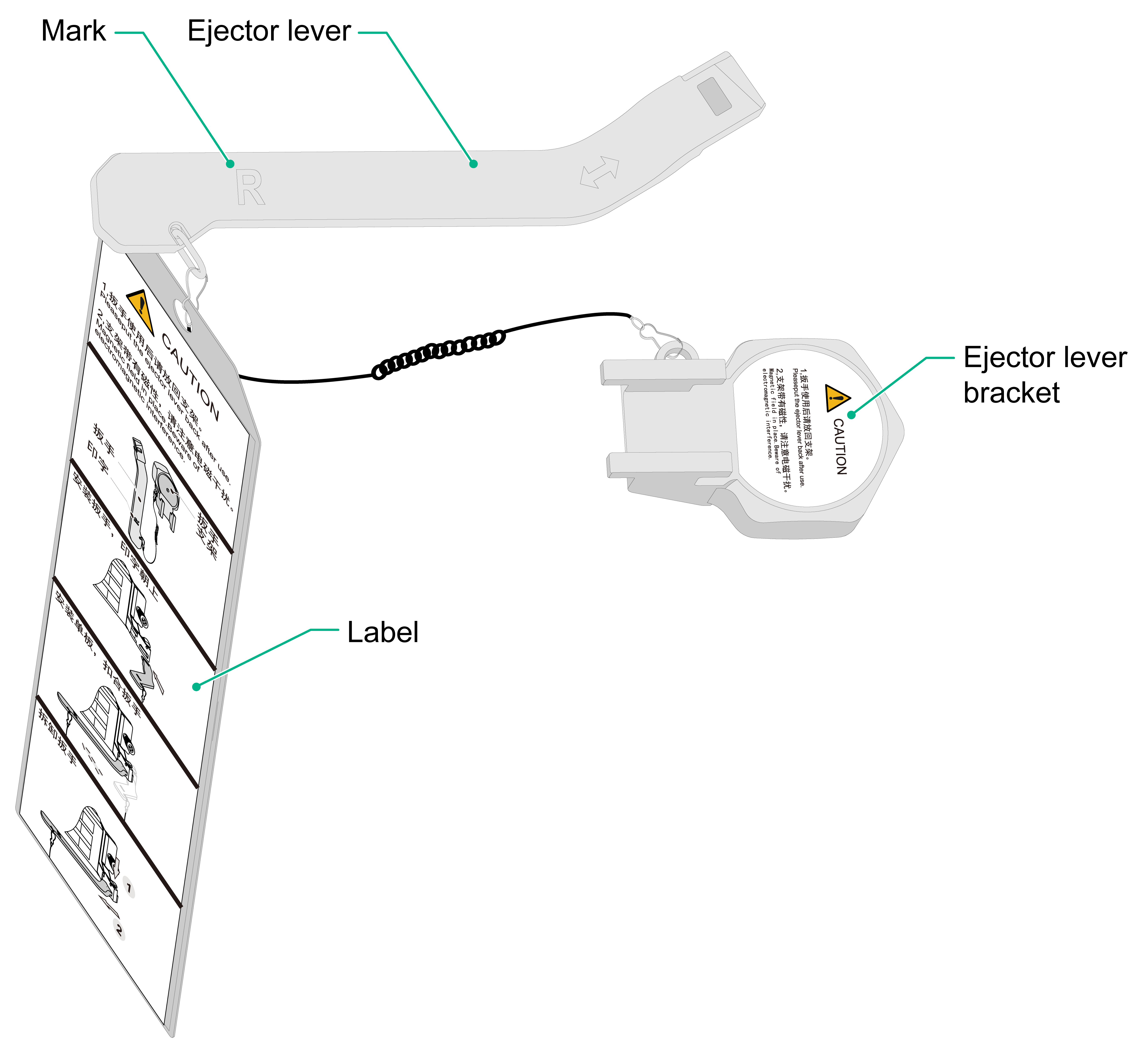
CAUTION: · Put the detachable ejector lever back on its holder after use and then attach it to the chassis or rack for future use. · The ejector lever holder is magnetic. Be aware of electromagnetic interference. · Do not use only one detachable ejector lever to install or remove an interface module. · Do not hold detachable ejector levers to lift an interface module. |
Figure 7-5 Detachable ejector lever
To install an interface module that uses detachable ejector levers:
1. Wear an ESD wrist strap. Make sure the wrist strap makes good skin contact and is reliably grounded.
2. Remove the filler panel from the target interface module slot.
Keep the removed filler panel secure for future use.
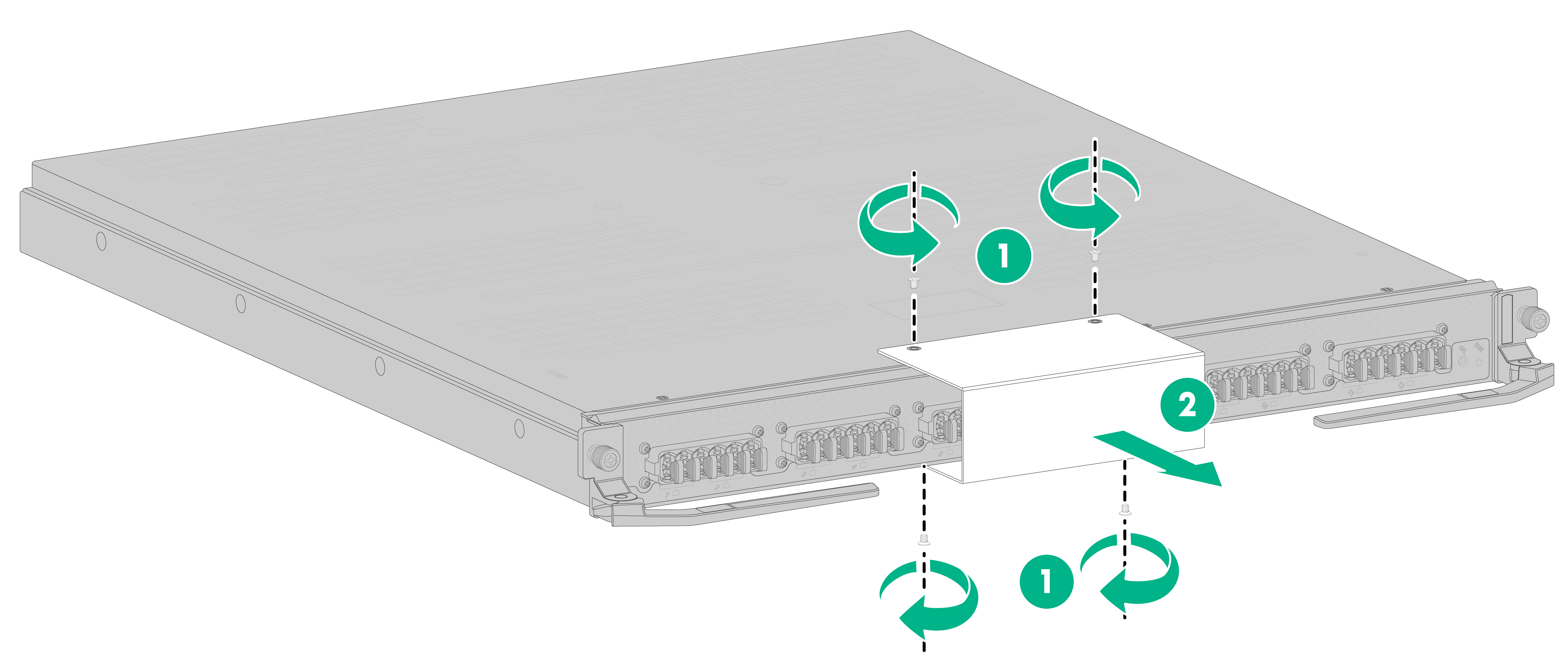
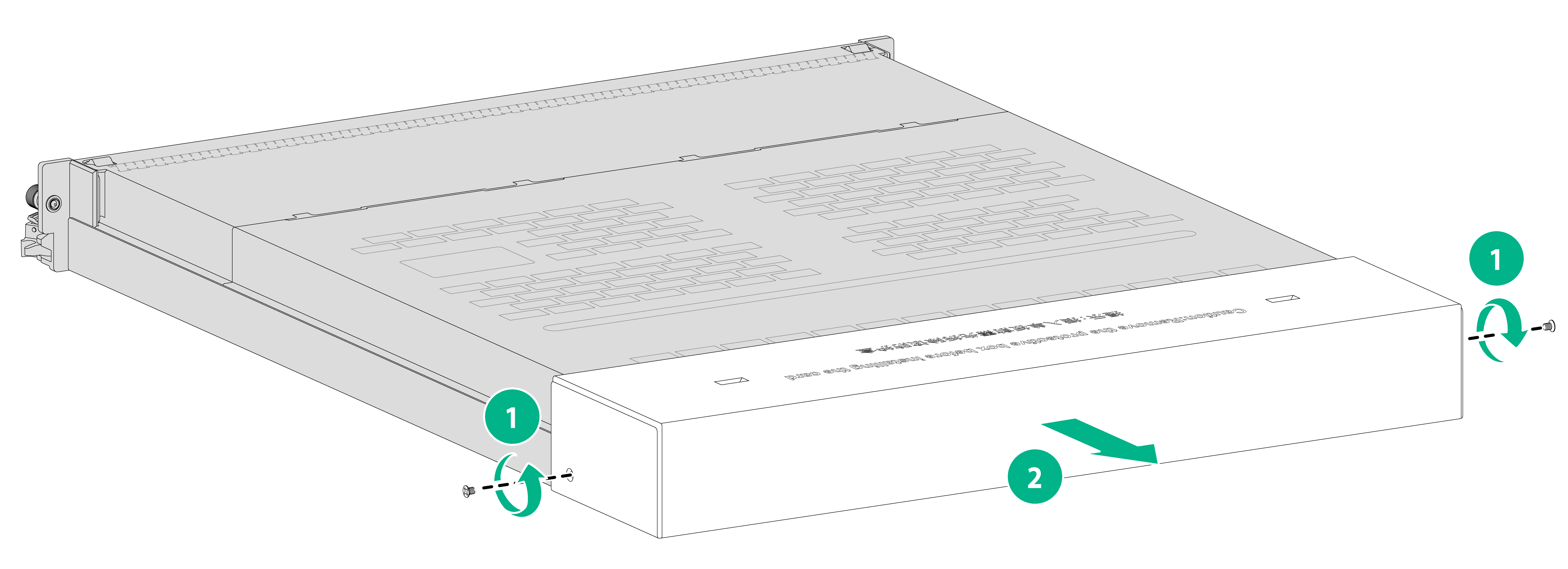
3. Remove the protection box (if any) from the connector side of the interface module, as shown in Figure 7-6.
Keep the removed protection box secure for future use.
The number of screws for securing the protection box in Figure 7-6 is for illustration only and the actual number of screws on your interface module might differ from that.
Figure 7-6 Removing the protection box
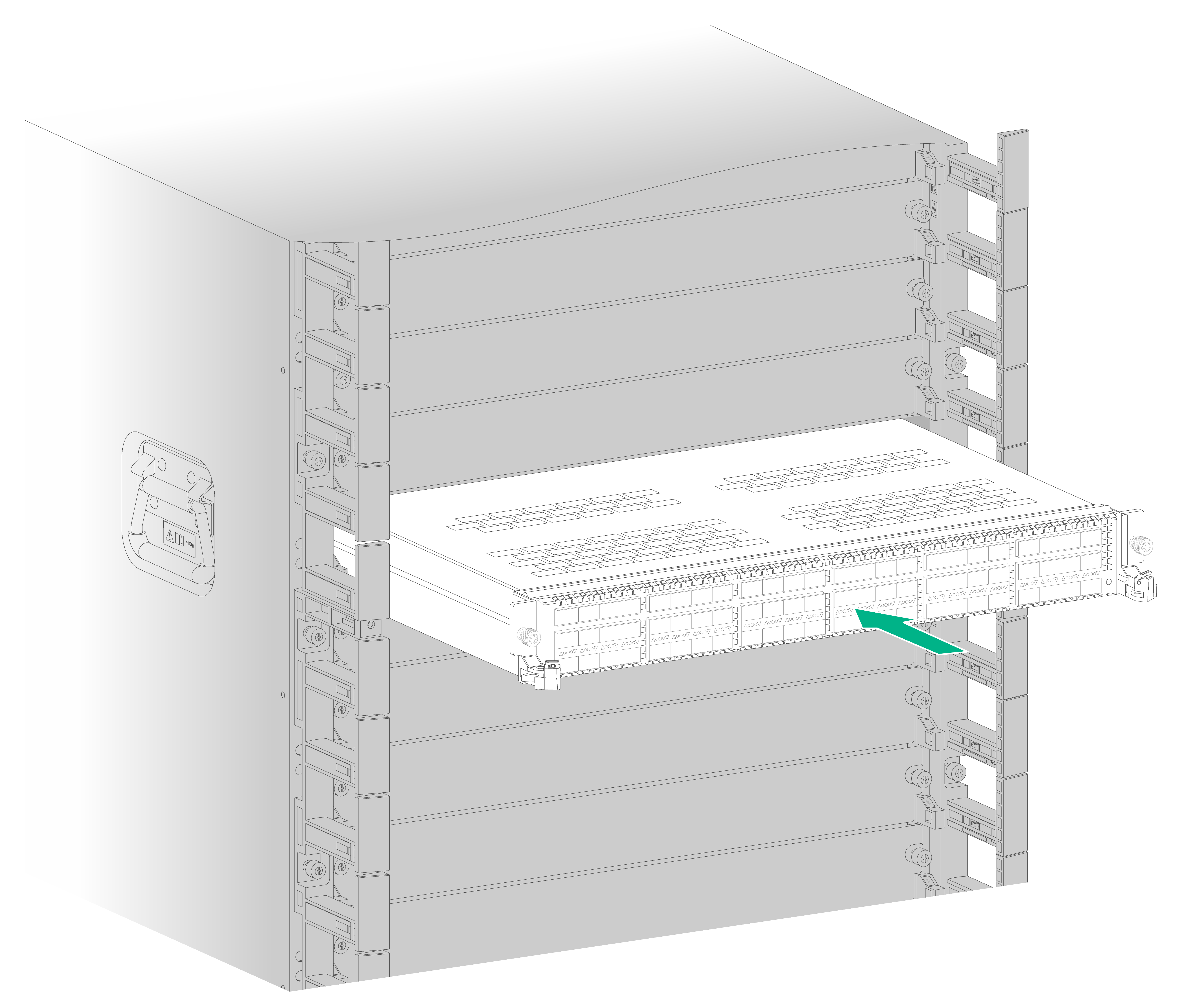
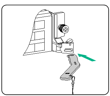
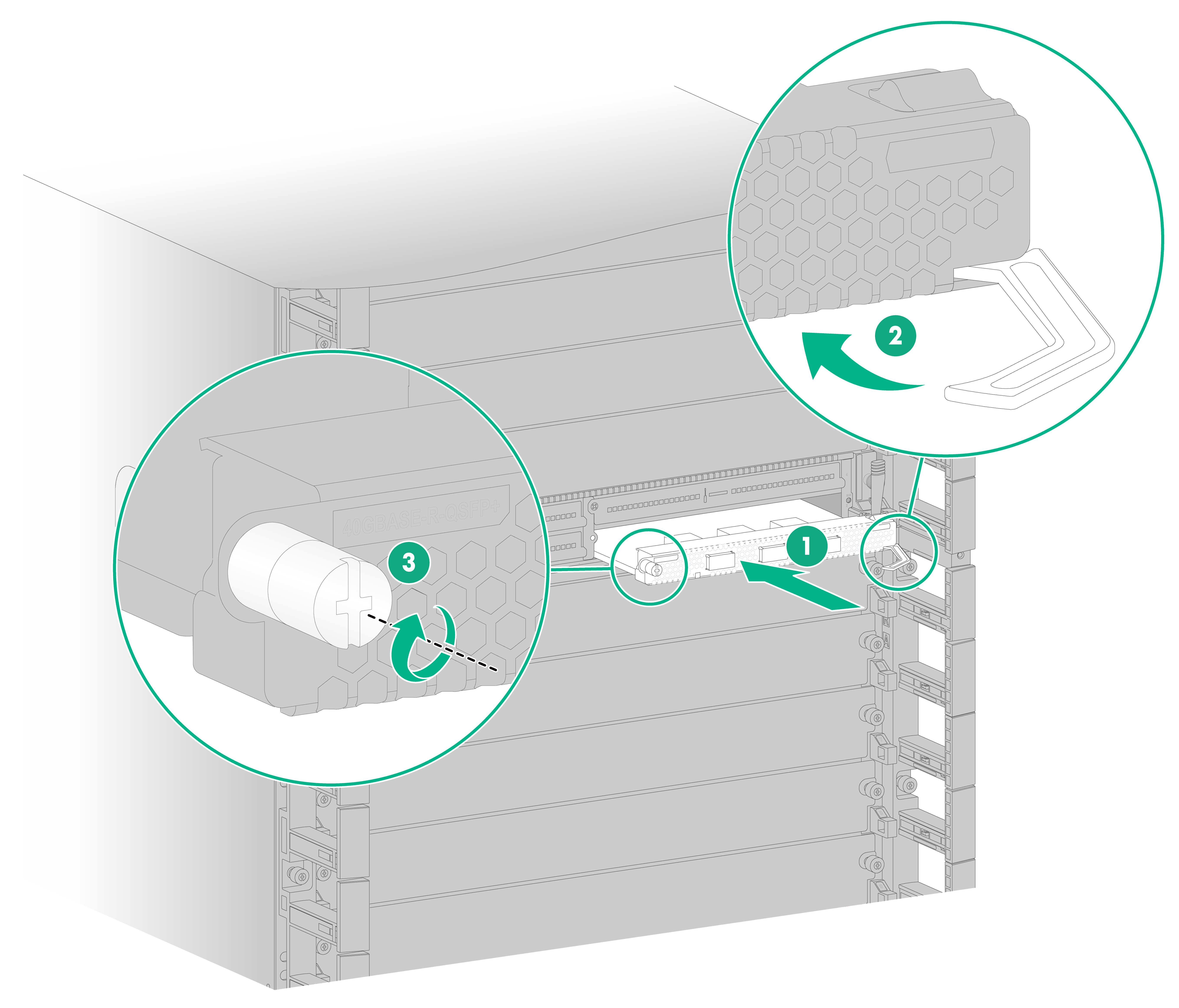
4. Correctly orient the interface module. Align the module with the slot and push it steadily into the slot along the guide rails until about half of the module is in the slot.
Figure 7-7 Installing an interface module that uses detachable ejector levers
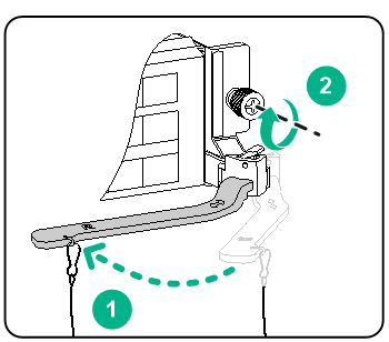
5. Attach the ejector lever holders to the chassis or rack and then remove the ejector levers from the holders.
6. Identify the L and R marks on the ejector levers and attach them to left and right ejector lever retainers of the interface module, with the lettering on the ejector levers facing upward.
Figure 7-8 Installing an ejector lever
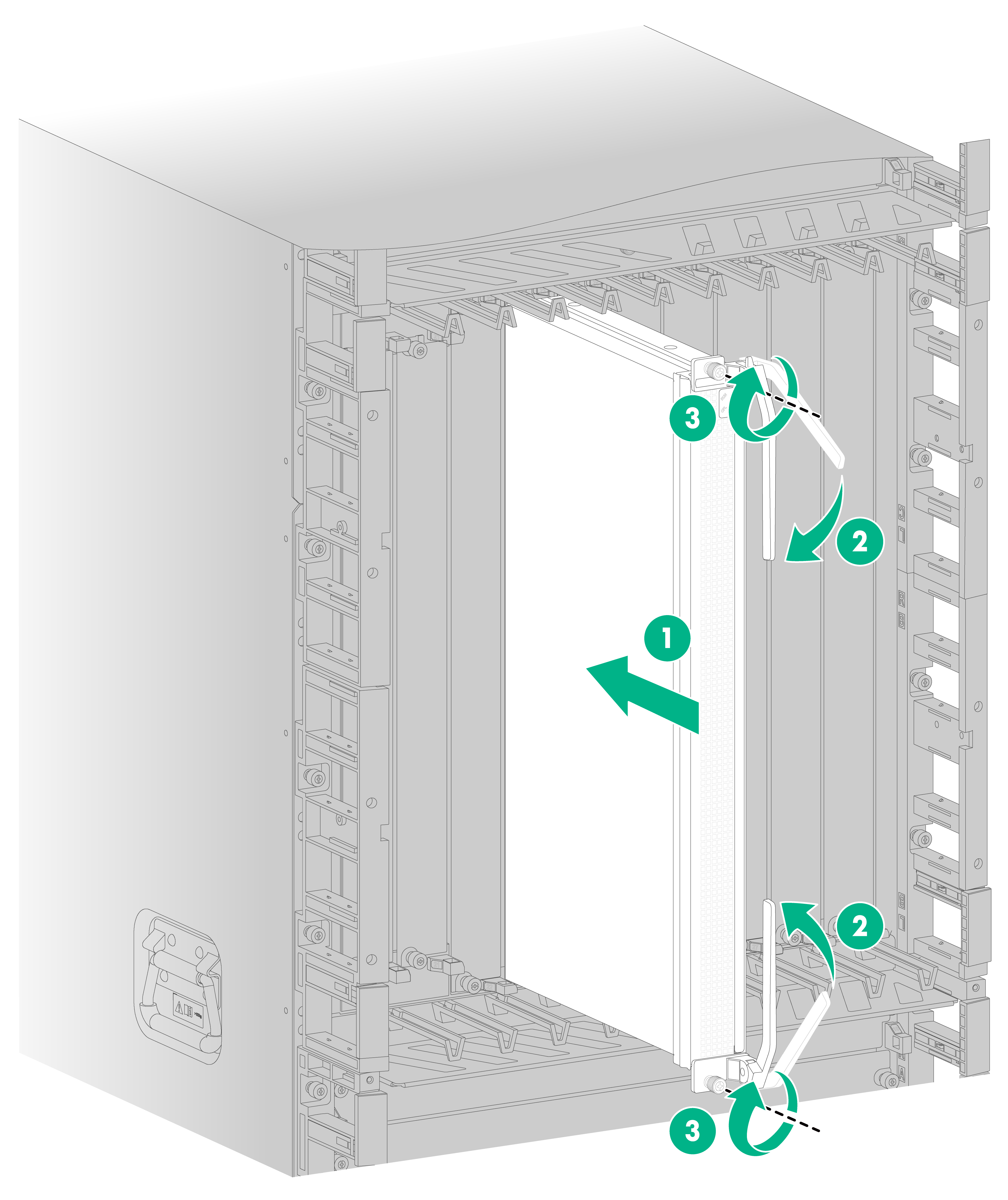
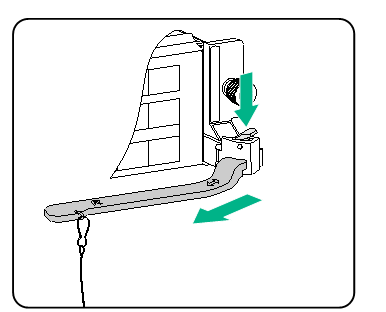
7. Open the ejector levers and continue to push the module by its middle part on the front panel until you cannot push it any further.
8. As shown in Figure 7-9, close the ejector levers until they come in close contact with the front panel. Use a Phillips screwdriver to fasten the captive screws on the interface module.
Figure 7-9 Closing an ejector lever
9. As shown in Figure 7-10, press the spring tab on each ejector lever retainer to remove the ejector levers. Place the ejector lever back on their holders and keep them secure for future use.
Figure 7-10 Removing an ejector lever
Installing an interface module that uses general ejector levers
1. Wear an ESD wrist strap. Make sure the wrist strap makes good skin contact and is reliably grounded.
2. Remove the filler panel from the target interface module slot.
Keep the removed filler panel secure for future use.
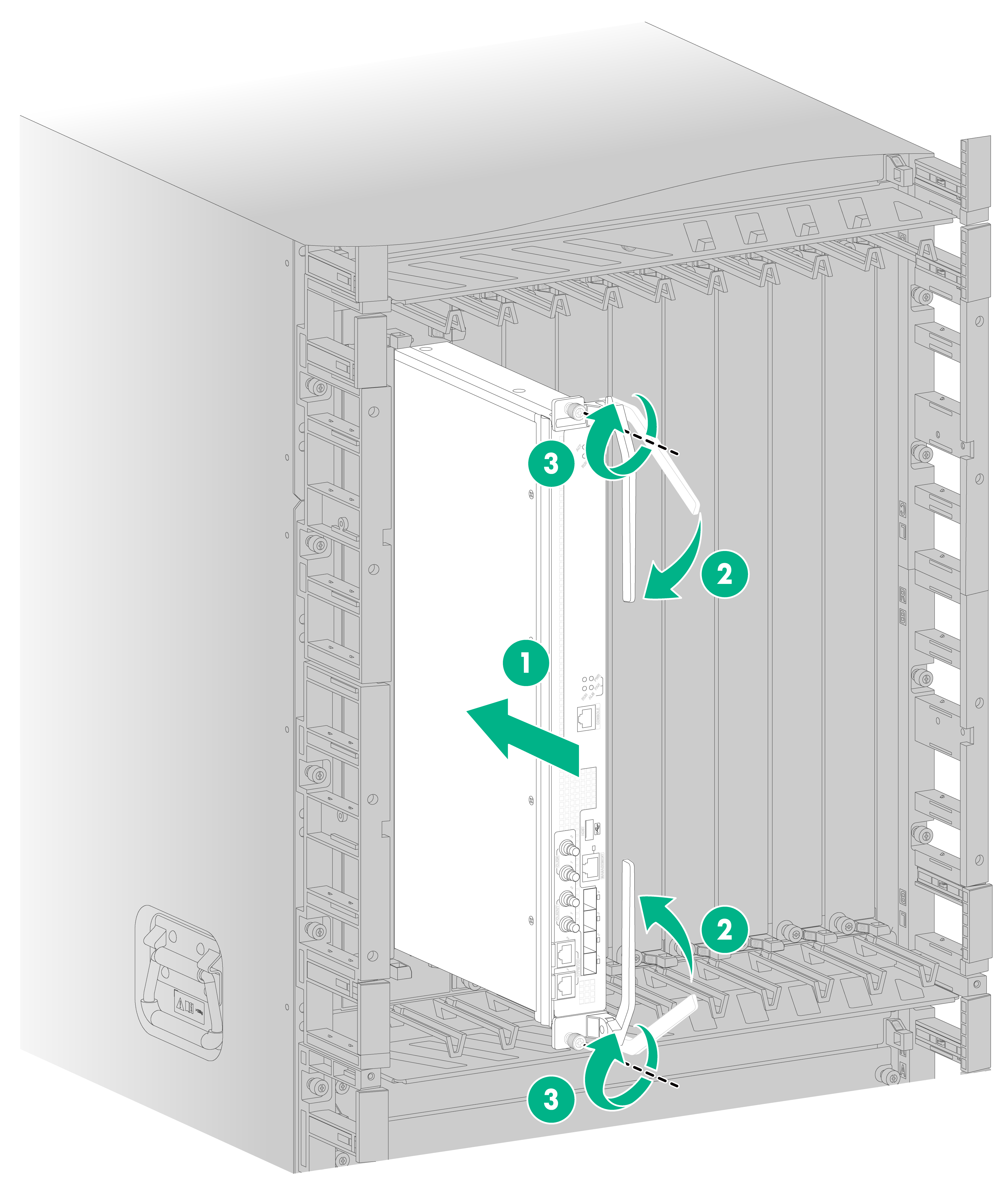
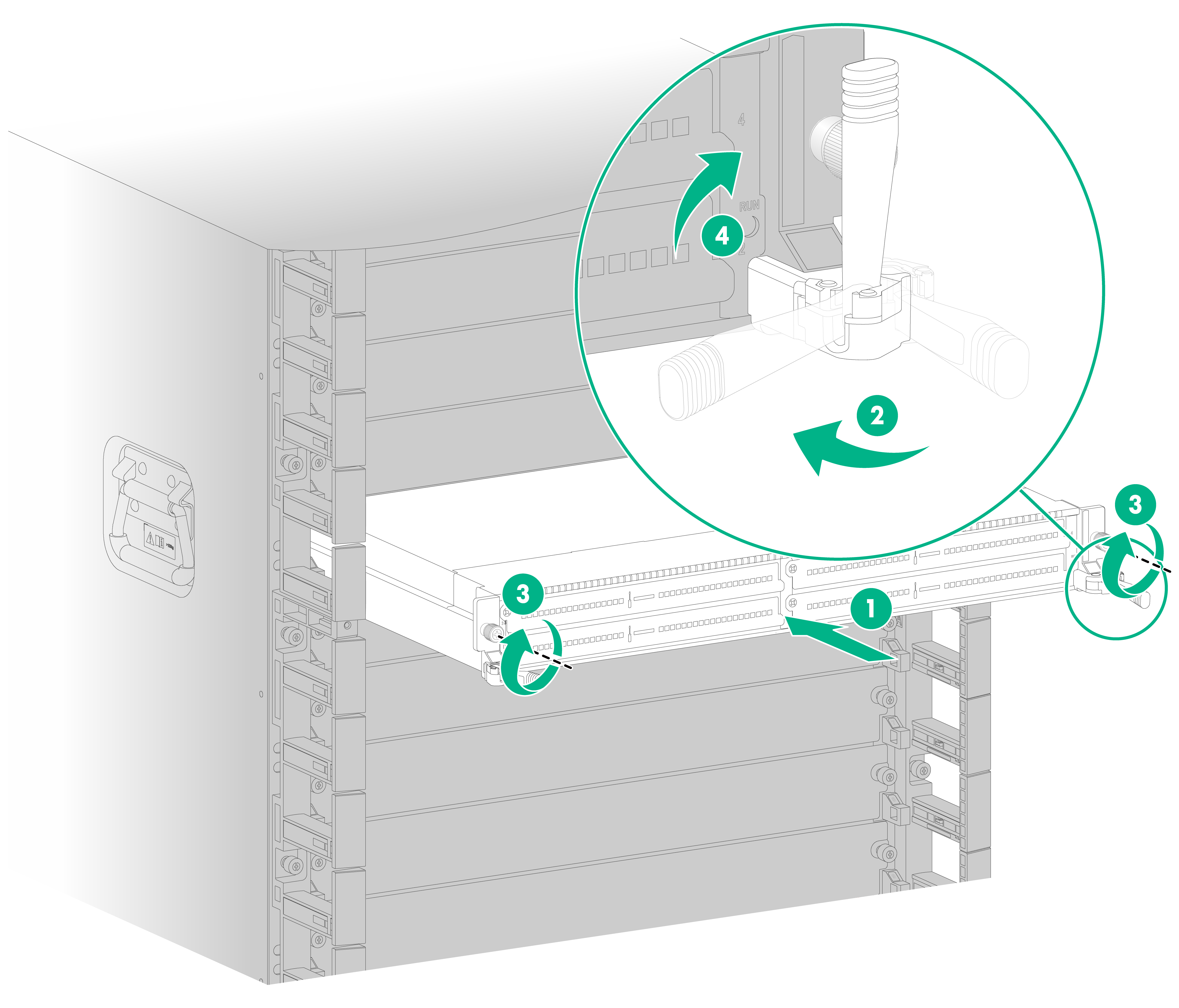
3. As shown in Figure 7-11, correctly orient the interface module and align it with the interface module slot. Gently push the interface module into the slot along the guide rails and then fully open the ejector levers on the module.
4. Continue to push the interface module by its middle part on the front panel until the ejector levers touch the slot edges.
5. Close the ejector levers until they come close contact with the front panel of the interface module.
6. Use a Phillips screwdriver to fasten the captive screws on the interface module.
7. Pivot up the ejector levers on the interface module.
Figure 7-11 Installing an interface module that uses general ejector levers
Installing interface subcards
For the interface subcard compatibility with interface modules, see H3C CR19000-20 Core Router Hardware Information and Specifications.
If you are not to install an interface subcard in a slot an interface module, keep the filler panel in the slot.
To install an interface subcard:
1. Wear an ESD wrist strap. Make sure the wrist strap makes good skin contact and is reliably grounded.
2. Remove the filler panel from the target slot on the interface module.
Keep the removed filler panel secure for future use.
3. Correctly orient the interface subcard and open the right ejector lever of the interface subcard.
4. Insert the interface subcard into the slot and push it steadily into the slot along slide rails.
5. Continue to push the interface subcard by its middle part on the front panel until you cannot push it any further.
6. Close the right ejector lever until it comes in close contact with the front panel.
7. Use a screwdriver to fasten the captive screw on the interface subcard.
Figure 7-12 Installing an interface subcard
8 Connecting signal cables
Installing transceiver modules and optical fibers
|
|
WARNING! Disconnected optical fibers or transceiver modules might emit invisible laser light. Do not stare into beams or view directly with optical instruments when the router is operating. |
|
|
CAUTION: · Before installing a transceiver module, remove the optical fibers, if any, from it. For more information about installing transceiver modules, see the installation guide for the transceiver modules. · If you are not to use a fiber port or transceiver module, insert dust plugs into the port or module. If you are not to connect an optical fiber, install dust caps for the fiber connector. |
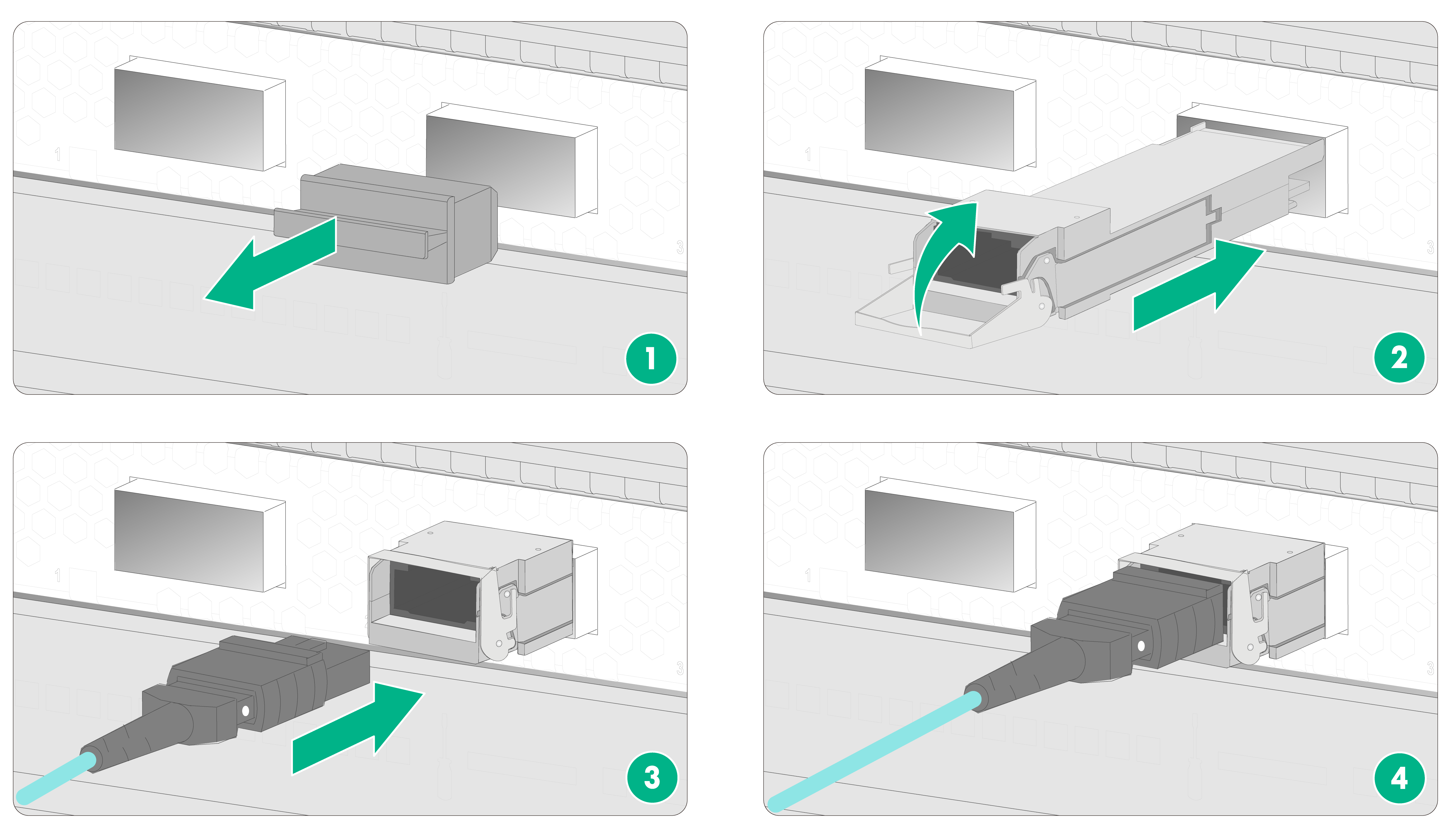
To install a transceiver module and optical fiber:
1. Wear an ESD wrist strap. Make sure the wrist strap makes good skin contact and is reliably grounded.
2. Remove the dust plug from the target fiber port.
3. Pull the bail latch on the transceiver module upwards.
Skip this step if the bail latch is plastic.
4. Take the transceiver module by its two sides and align it with the fiber port.
5. Push the transceiver module gently into the port until it is firmly seated in the fiber port.
Use tweezers to insert the transceiver module into the fiber port if the interface module is densely populated with transceiver modules.
6. Remove the dust plug and dust cap from the transceiver module and fiber connector, respectively.
7. Connect the optical fiber to the transceiver module.
¡ LC connector—Align the connector with the transceiver module and push it into the transceiver module slightly until it clicks into place.
¡ MPO connector—Orient the connector with the white spot on it facing right. Insert the MPO fiber connector straight into the transceiver module and push it slightly forward until it clicks into place.
8. Use cable ties at a spacing of 150 mm (5.91 in) to bind optical fibers.
9. Label optical fibers according to the cable labeling specifications.
Figure 8-1 Installing a transceiver module and optical fiber (LC port)
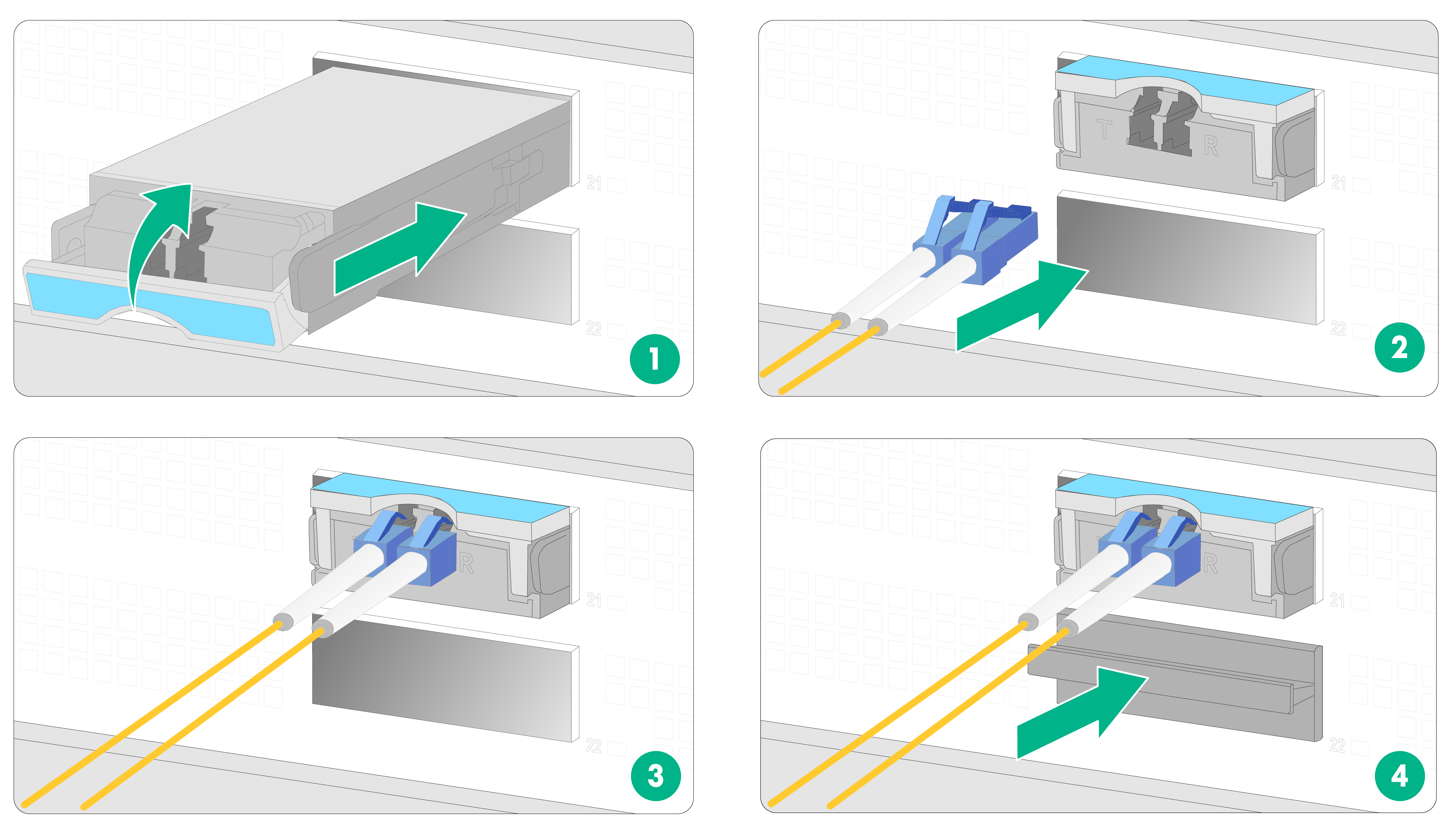
Figure 8-2 Installing a transceiver module and optical fiber (MPO port)
Connecting an optical fiber to a multi-chassis fabric module
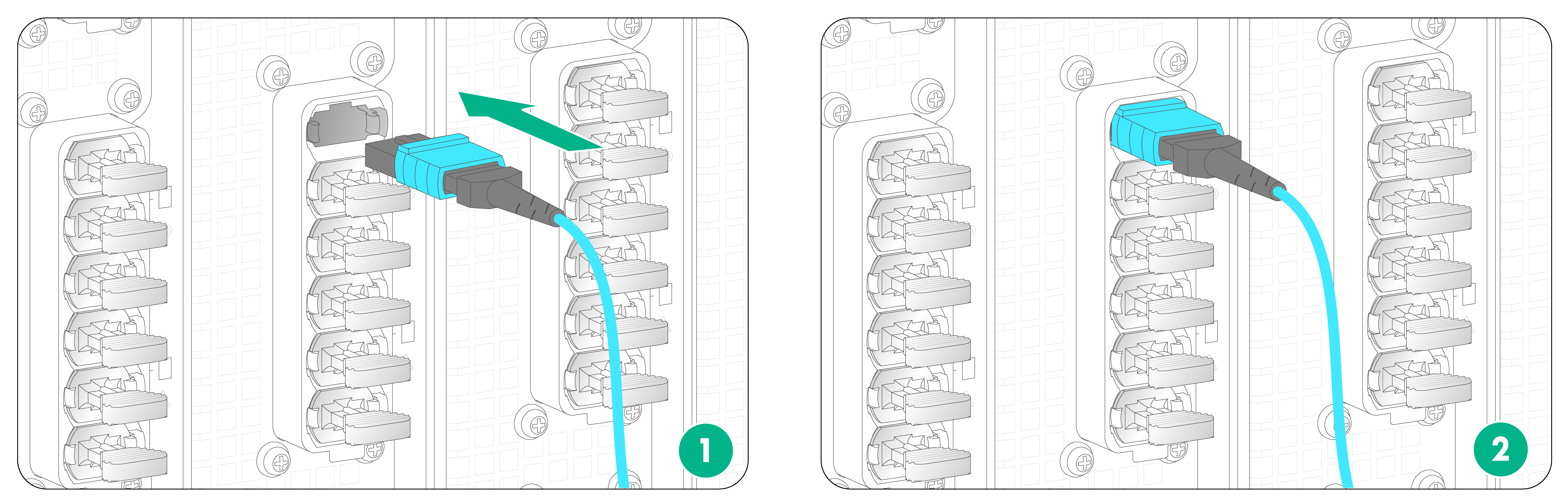
A multi-chassis fabric module has a built-in transceiver module in each cluster port. You can connect an optical fiber with an MTP connector to a cluster port on the multi-chassis fabric module directly.
To connect an optical fiber to a cluster port on a multi-chassis fabric module:
1. Wear an ESD wrist strap. Make sure the wrist strap makes good skin contact and is reliably grounded.
2. Remove the dust plug from the target cluster port on the multi-chassis fabric module.
3. Remove the dust cap from the fiber connector.
4. Hold the MTP connector by its part marked "PULL". Align the guide key on the connector with the groove in the port, and push the connector into the fiber port slightly until it clicks into place.
5. Use cable ties at a spacing of 150 mm (5.91 in) to bind optical fibers.
6. Label optical fibers according to the cable labeling specifications.
Figure 8-3 Connecting an optical fiber with an MTP connector to a cluster port
Connecting cables to E1 ports
Cables for connecting E1 ports
You can use an E1 cable to connect an E1 port (HM96 male connector). Typically, an E1 cable has an HD96 female connector at one end and multiple BNC, RJ-45, or SMB connectors at the other end.
When connecting an E1 cable, you might need also coaxial connectors and 75-ohm E1 adapter cables. No coaxial connectors and 75-ohm E1 adapter cables are provided with interface subcards. Purchase them yourself as needed.
Connecting an E1 cable
|
|
CAUTION: To avoid interface subcard or chassis damage, identify the target E1 port before your connection. Avoid connecting the cable to another port. |
Connecting an E1 120-ohm RJ-45 cable
1. Connect the HD96 connector of the E1 120-ohm cable to the HM96 connector on the interface subcard and fasten the screws on the connector.
2. Connect the RJ-45 connectors at the other end of the E1 cable to the peer device.
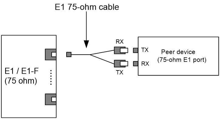
Connecting an E1 75-ohm BNC/SMB cable
The E1 75-ohm BNC cable and SMB cable use the same connection procedure. The following procedure connects an E1 75-ohm BNC cable.
To connect an E1 75-ohm BNC cable:
· If you do not need to extend the cable, perform these steps:
a. Connect the HD96 connector of the E1 75-ohm cable to the HM96 connector on the interface subcard and fasten the screws on the connector.
b. The other end of the cable provides multiple pairs of 75-ohm BNC connectors. Identify the number of each pair of BNC connectors. Connect the TX connector and the RX connector of the cable to the RX connector and the TX connector on the peer device, respectively.
Figure 8-4 Connecting an E1 75-ohm cable
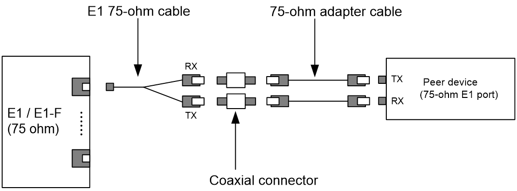
· If you need to extend the cable, connect each BNC connector of the E1 75-ohm cable to a coaxial connector and then use an E1 75-ohm adapter cable to connect the coaxial connector to the peer device.
Figure 8-5 Connecting an E1 75-ohm cable (using coaxial connectors and 75-ohm adapter cables)
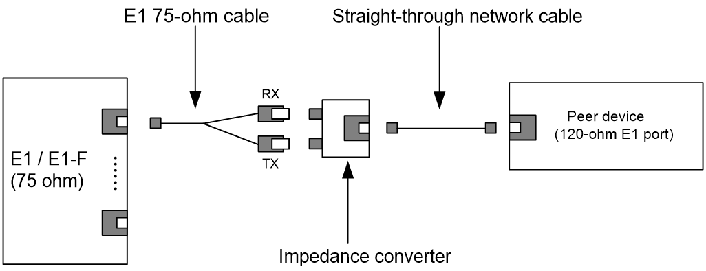
· If the impedance of the E1 port on the peer device is 120 ohms, you must use an impedance converter to adapt the impedance.
Figure 8-6 Connecting an E1 75-ohm cable (using an impedance converter)
Routing signal cables
The router provides cable management brackets along the left and right edges of the front panel and cable management fingers at the top and bottom edges of each MPU and fabric module slot.
As a best practice, route signal cables along the nearest cable management fingers and cable management brackets.
For more information about signal cable routing, see H3C CR19000-20 Core Routers Installation Guide.
9 Verifying the installation
Post-installation checklist
Table 9-1 Post-installation checklist
|
Item |
Requirements |
|
Installation location |
· No condensation is on the surface of the router or inside the router. · The router is clean and dust-free. · No packaging boxes, packaging bags, or other packaging materials are left around the chassis. · The air inlet and outlet vents of the router are not blocked, free of obstructions. |
|
Router |
· All components are installed correctly. · Each slot is installed with a module or filler panel. · Fan trays are installed correctly. |
|
Cables |
· The router is grounded reliably with the provided grounding cable. Both ends of the grounding cable are securely connected. · No switch or fuse is installed on the grounding cable. · The power cords are connected reliably and no short circuit has occurred on power input and output ends. · Power cords, grounding cables, and signal cables are routed and bound separately. · The cables are bound neatly with cable ties at an even distance. · The cable labels are correct, clear, and affixed to the cable in the same direction. |
|
Electricity safety |
· A circuit breaker is provided for each power cord. · Turn off the circuit breaker before you connect the power cord. |
Power-on check
|
|
WARNING! Before powering on the router, locate the power switch in the equipment room so that you can quickly shut power down when an electrical accident occurs. |
|
|
CAUTION: · The router uses two switches to achieve 1+1 redundancy. To power on the router, turn on both switches. To power off the router, turn off both switches. · Before powering on the router, make sure each fan tray has a fan tray installed. |
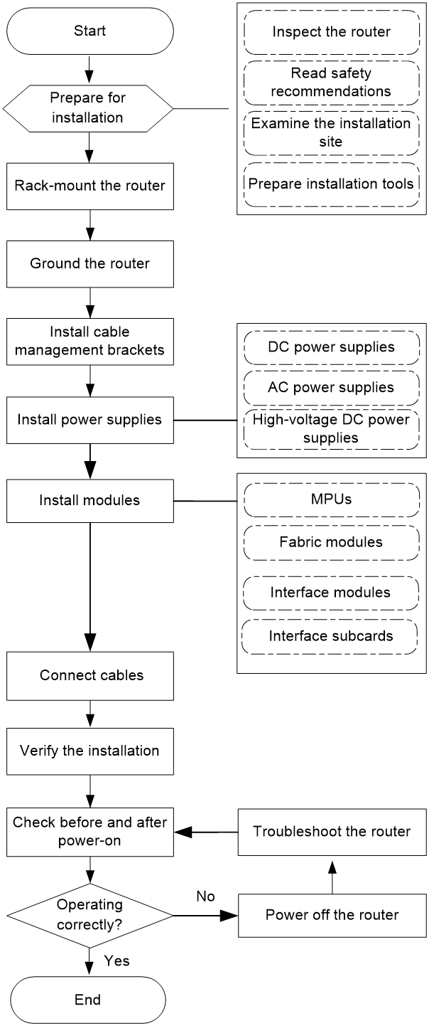
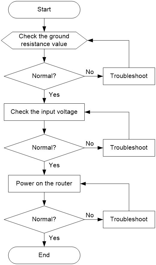
Power-on check flowchart
Figure 9-1 Power-on check flowchart
Checking the LEDs
After the router powers up, you can determine whether the router and the components are operating correctly by observing the LEDs on the MPUs and other components. When the router and components are operating correctly, the LEDs are as described in Table 9-2 and Table 9-3. If the LED states are not as described in Table 9-2 and Table 9-3, the router and components might be faulty. For more information about the LEDs, see H3C CR19000-20 Core Routers Hardware Information and Specifications.
Table 9-2 MPU LED descriptions
|
LED |
Status |
Description |
|
|
FAN |
OK |
Steady green |
All the fan trays are operating correctly. |
|
FAIL |
Off |
||
|
PWR |
OK |
Steady green |
All the installed power supplies are operating correctly. |
|
FAIL |
Off |
||
|
RUN |
Slow flashing green (4 Hz) |
The modules are loading software. |
|
|
Fast flashing green (0.5 Hz) |
The modules are operating correctly. |
||
|
ALM |
Off |
No alarm has occurred on the system |
|
|
ACT |
Steady green |
The MPU is in active mode of the chassis or system. |
|
|
Flashing green |
The router is in cluster mode, and the MPU is in standby mode. |
||
|
Off |
The router is in single chassis mode, and the MPU is in standby mode. |
||
|
|
NOTE: The PWR FAIL LED on the MPU will turn on if one of the installed power supplies fails to power up (the power cord is not connected, the power cord is loose or in bad condition, or the circuit breaker for it is turned off). |
Table 9-3 Component LED descriptions
|
LED |
Status |
Description |
|
|
Fabric module LED |
RUN |
Fast flashing green (4 Hz) |
The fabric module is loading software. |
|
Slow flashing green (0.5 Hz) |
The fabric module is operating correctly. |
||
|
Interface module LED |
RUN |
Fast flashing green (4 Hz) |
The module is loading software. |
|
Slow flashing green (0.5 Hz) |
The module is operating correctly. |
||
|
Fan tray LED |
OK/FAIL |
Steady green |
The fan tray is operating correctly. |
|
Power supply LED |
IN OK OUT OK |
Steady green |
The power supply is operating correctly. |
|
|
IMPORTANT: · To check the power supply LEDs, first remove the air filter. Press the blue locking tabs at both sides of the air filter to remove the air filter from the top hood. · The fan trays in the top four rows (FAN 1 to FAN 12), in the middle three rows (FAN 13 to FAN 21), and in the bottom four rows (FAN 22 to FAN 33) power up after a three-second delay, two-second delay, and four-second delay, respectively upon power-up of the router. Before a fan tray powers up, its OK/FAIL LED is red. |
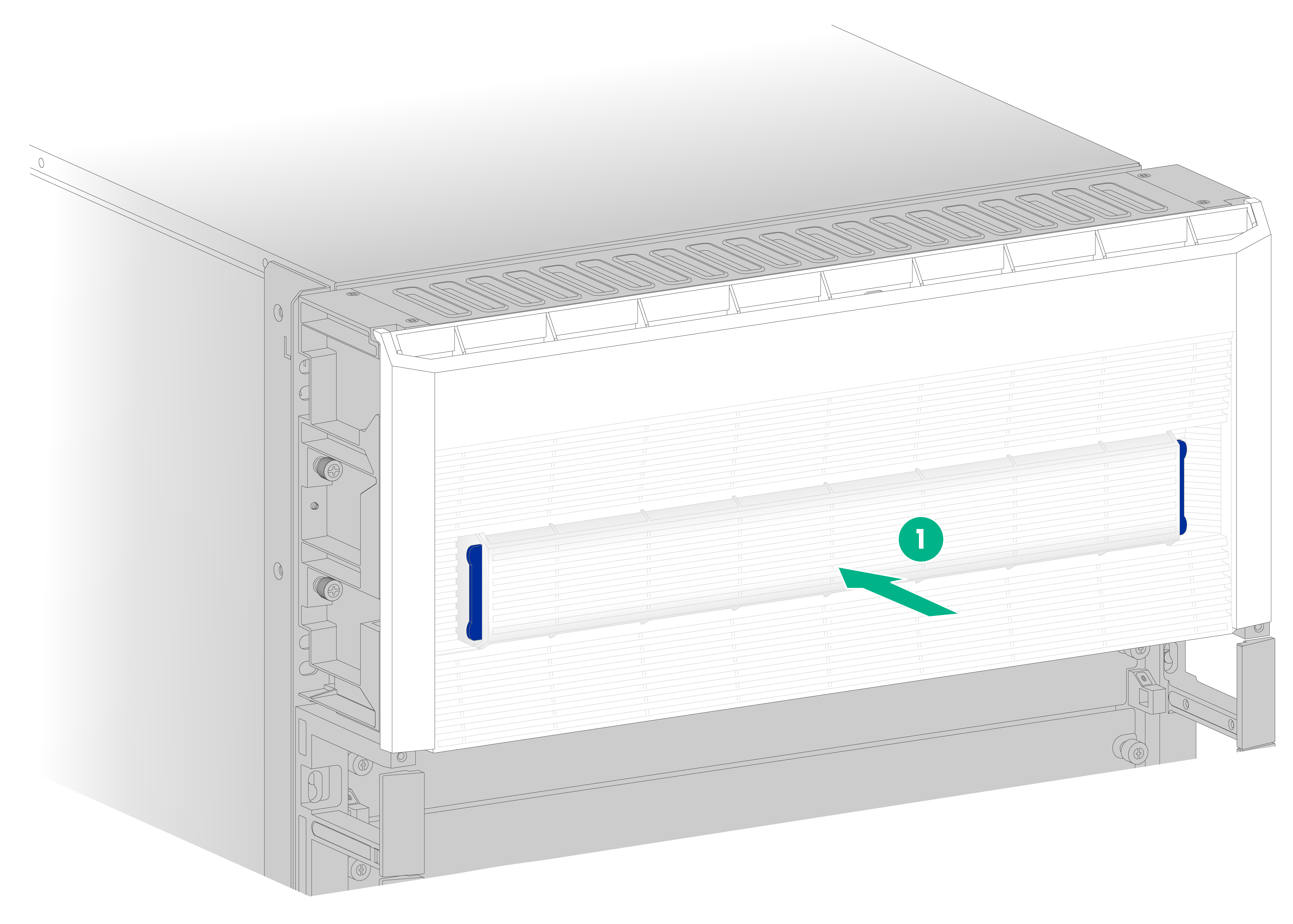
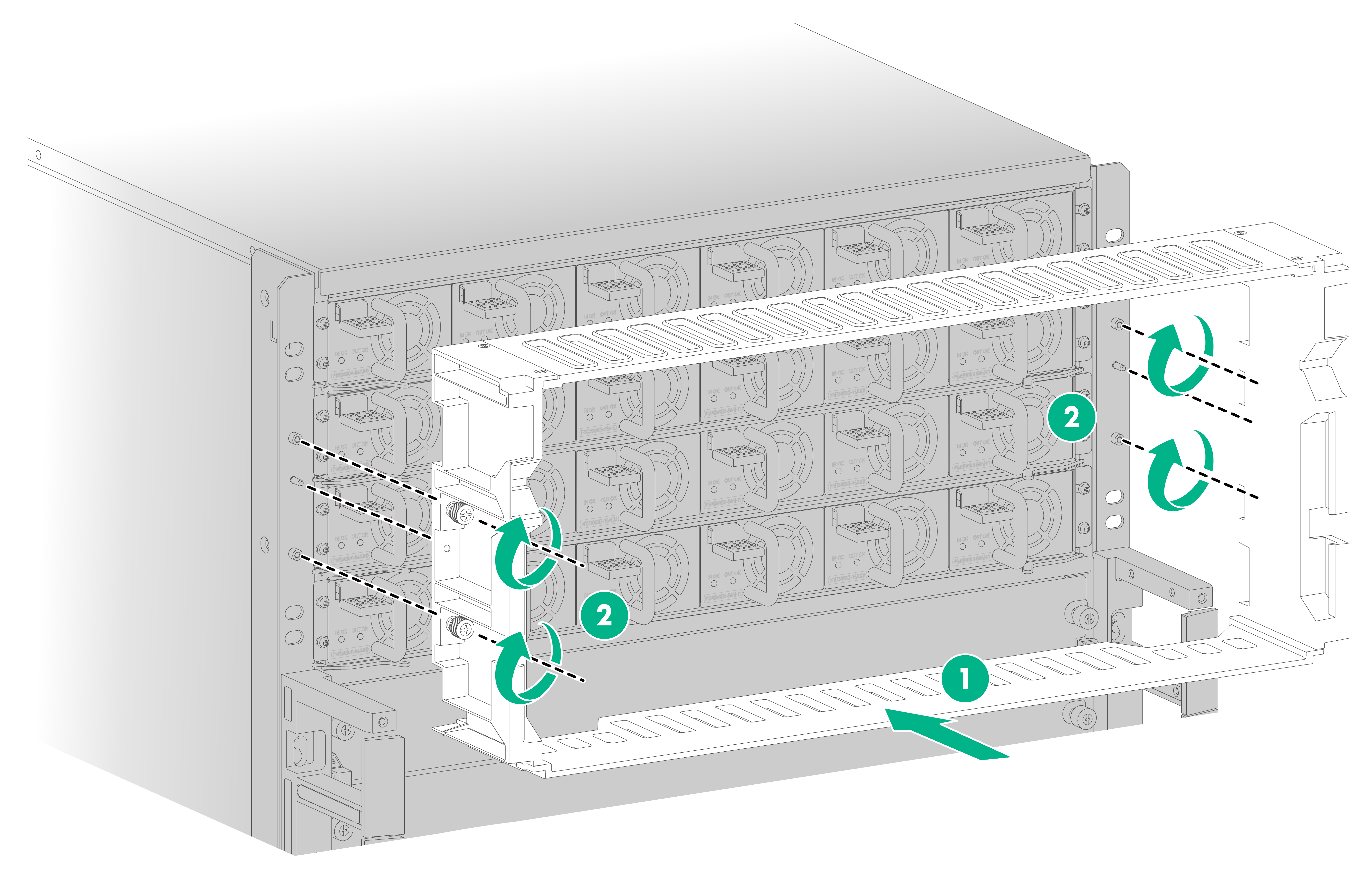
Installing the top hood and air filter
1. Align the holes in the top hood with the pins on the mounting brackets. Push the top hood so that the pins enter the holes in the top hood.
2. Fasten the captive screws to secure the top hood.
Figure 9-2 Installing the top hood
3. Position the air filter over the top hood, and then push the air filter until it is seated into the top hood.
Figure 9-3 Installing an air filter