- Table of Contents
- Related Documents
-
| Title | Size | Download |
|---|---|---|
| 01-text | 2.16 MB |
Contents
Pre-installation configuration
Configuring network parameters
Setting the date, time, and time zone
Selecting the components to install
Changing network parameters after installation of CAS
Setting the system time for each server
Configuring link aggregation for the management network
Configuring dynamic link aggregation
Configuring static link aggregation
Appendix Building a bootable USB drive
Using Linux DD mode to build a USB bootable flash drive
Using Rufus to build a USB bootable flash drive
About CAS
H3C Cloud Automation System (CAS) is a resources management platform for constructing a cloud computing infrastructure. It provides industry-leading virtualization management solutions for the cloud computing infrastructure in the data center, and implements centralized management and control over cloud computing. It offers a unified user-friendly management interface for all hosts and virtual machines (VMs) in the data center, not only improving management efficiency and simplifying routine work, but also reducing IT maintenance complexity and management costs.
Features and functionalities
CAS is the software suite for constructing H3Cloud solutions. It delivers the following features and functionalities:
· Server infrastructure consolidation
· Centralized and unified management on computing, network, and storage resources
· High availability and dynamic resource scheduling features to ensure data center service continuity
· Rapid migration and backup of VMs
· Multi-tenant isolation
· User self-service portal
· Cloud business workflows
· Open API interfaces to ensure interoperability between clouds
Components
CAS contains the following components:
· Cloud Virtualization Kernel—CVK is the kernel that runs between the network infrastructure and the customer operating system. It helps eliminate the difference between the underlying heterogeneous hardware and the dependence of the operating system on the hardware devices and drivers. CVK enhances the performance of CAS in hardware compatibility, high reliability, availability, scalability, and performance optimization.
· Cloud Virtualization Manager—CVM provides virtualization management on computing, network, and storage resources in the data center as well as automated services for upper layer applications. CVM provides the following services:
¡ Virtual computing, networks, and storage
¡ High availability
¡ Dynamic resource scheduling (DRS)
¡ VM backup and disaster recovery
¡ VM template management
¡ Cluster file system
¡ Virtual switch (vSwitch) policies
Preparing for installation
Server compatibility with CAS
H3C CAS is a hardware-assisted virtualization system. To run H3C CAS, the server must support the Intel-VT or AMD-V technology. ARM servers must support ARM VHE. For server compatibility with H3C CAS, see Hardware and Software Compatibility with H3C CAS.
Server requirements
Management server
|
|
IMPORTANT: · To deploy CVM on a CAS VM, make sure the operating system of the VM is CAS/CVM OS (64-bit). · To deploy CVM on a VM of other hypervisors, make sure the operating system of the VM is CentOS 7 (64-bit) and the VM is enabled with port monitoring. |
A management server in the data center performs centralized management on hosts. You must install the CAS CVK and CVM components on the management server.
Table 1 describes the hardware requirements for a management server. If you are not to assign the management server to a host pool or create and run VMs on the management server, the hardware requirements for the server are as shown in Table 1, and the CPUs on the sever are not required to support virtualization. If you are to assign the management server to a host pool and create and run VMs on the management server, the hardware requirements for the server are as shown in Table 2.
Table 1 Management server hardware requirements
|
Quantity of servers and VMs to manage |
CPUs |
Memory |
Storage |
Remarks |
|
Server: < 20 VM: < 200 |
≥ 4 |
≥ 8 GB |
300 GB |
Can be deployed on servers (recommended) or VMs. |
|
Server: 20 to 50 VM: 200 to 1000 |
≥ 4 |
≥ 16 GB |
600 GB |
Can be deployed on servers (recommended) or VMs. |
|
Server: 50 to 100 VM: 1000 to 3000 |
≥ 8 |
≥ 32 GB |
2 × SASs (300G) in RAID1 |
Must be deployed on servers. |
|
Server: 100 to 256 VM: 3000 to 5000 |
≥ 12 |
≥ 64 GB |
2 × SSDs (960G) in RAID1 |
Must be deployed on servers. |
|
Server: 256 to 512 VM: > 5000 |
≥ 16 |
≥ 128 GB |
2 × SSDs (960G) in RAID1 |
Must be deployed on servers. |
Virtualization server
A virtualization server is a physical host that has VMs running on it. You only need to install CAS component CVK on the virtualization server. Table 2 describes the recommended hardware requirements for a virtualization server.
Table 2 Virtualization server hardware requirements
|
Item |
Specification |
|||
|
CPU (above 2 GHz as a best practice) |
Two CPUs, four cores per CPU |
Four CPUs, two or four cores per CPU |
Eight CPUs, two, four, or more cores per CPU |
|
|
Memory |
≥ 16 GB |
≥ 32 GB |
≥ 64 GB |
|
|
GE/10-GE NIC |
Without using external storage |
≥ 4 |
≥ 4 |
≥ 4 |
|
Using FC storage |
≥ 4 |
≥ 4 |
≥ 4 |
|
|
Using IP storage |
≥ 6 |
≥ 6 |
≥ 6 |
|
|
Built-in drive (using an external drive array) |
2 |
2 |
2 |
|
|
CD/DVD ROM |
1 |
1 |
1 |
|
|
Power supply |
1+1 redundancy |
1+1 redundancy |
1+1 redundancy |
|
Required information
Before installing CAS, collect the following information:
· Server name
· Management network interface and its IP address
· Whether to install CVM
· Root password
· Disk partitioning method
Planning networks and storage
Planning networks
Restrictions and guidelines
· As a best practice to avoid single point of failures, configure NIC bonding.
· When IP SAN storage is used, configure two management NICs, two storage NICs, and two service NICs for a server. When FC SAN storage is used, configure two management NICs and two service NICs for a server.
· When FC SAN storage is used, configure two FC HBAs for a server to access different FC switches.
· As a best practice, use stacked switches. For example, you can set up H3C IRF fabrics.
· If the management network switch is enabled with STP, you must configure the interfaces that connect the switch to the management NICs of the CVK hosts as STP edge ports.
· A server can have only one default gateway, and an IP address is optional to a service NIC.
· To avoid VM migration and vSwitch selection failures, make sure all hosts in a cluster are consistent in the name of the vSwitch for a specific network.
Typical networking schemes
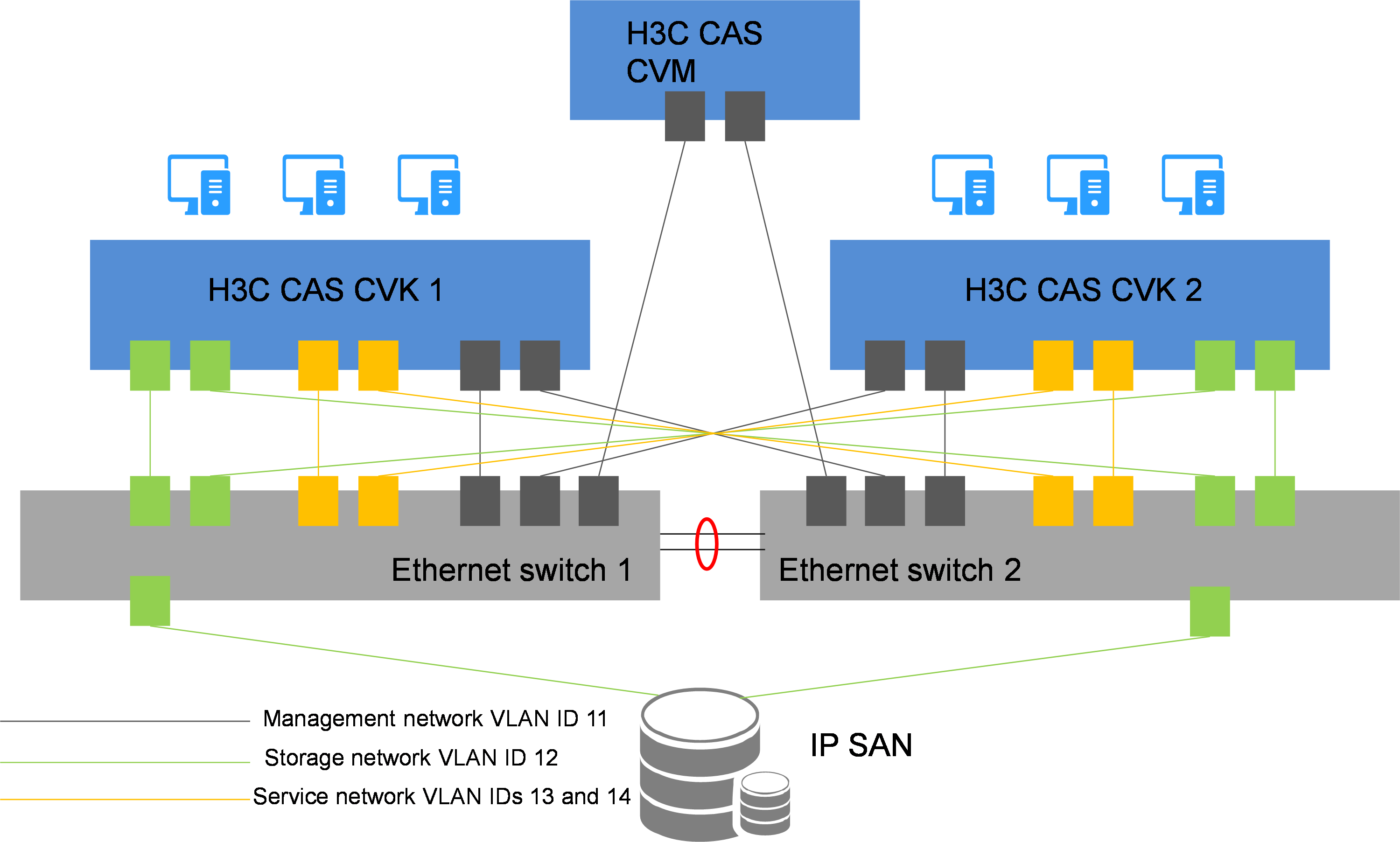
Typical IP SAN networking scheme
As shown in Figure 1:
· Configure two bonded NICs for the CVM host (management host), and connect each of them to an Ethernet switch. CVM hosts do not deliver VM services.
· Configure the following NICs for a CVK host (service host):
¡ Configure two bonded management NICs, and connect each of them to an Ethernet switch.
¡ Configure two bonded storage NICs, and connect each of them to an Ethernet switch.
¡ Configure two bonded service NICs, and connect each of them to an Ethernet switch.
· Configure two bonded NICs for the IP SAN, and connect each of them to an Ethernet switch.
· Configure VLANs to isolate the management, storage, and service networks.
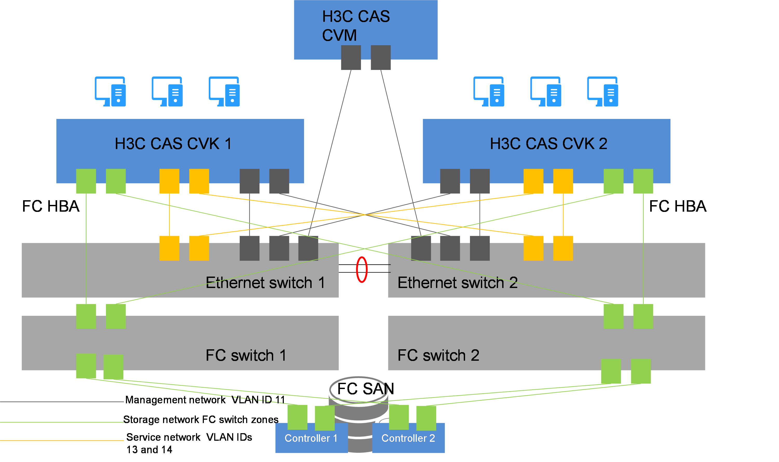
Typical FC SAN networking scheme
As shown in Figure 2:
· Configure two bonded NICs for the CVM host (management host), and connect each of them to an Ethernet switch. CVM hosts do not deliver VM services.
· Configure NICs and FC HBAs for a CVK host (service host) as follows:
¡ Configure two bonded management NICs, and connect each of them to an Ethernet switch.
¡ Configure two bonded service NICs, and connect each of them to an Ethernet switch.
¡ Configure a dual-port FC HBA, connect each port to an FC switch, and configure multipathing.
· Configure a dual-port FC HBA for the FC SAN, connect each port to an FC switch, and configure multipathing.
|
|
NOTE: Cross connections and multipathing ensure link redundancy and improve service stability. |
· Configure VLANs to isolate the management and service networks.
Planning server networks
CAS requires management, service, and storage networks isolated through VLAN. Therefore, to add a server to a CAS cluster, you must prepare three (two if FC SAN is used) NICs for the server. For a FlexServer R390 server, you must also prepare an iLO NIC with an IP address in the management network for the server.
Table 3 gives an example for IP address assignment in a scenario with the following networks planned:
· Management network—The network address is 192.168.11.0/24, the gateway address is 192.168.11.254, and the VLAN ID is 11.
· Storage network—The network address is 192.168.12.0/24, the gateway address is 192.168.12.254, and the VLAN ID is 12.
· Service network—The network address is 192.168.13.0/24, the gateway address is 192.168.13.254, and the VLAN ID is 13.
|
Server |
iLO NIC (VLAN 11) |
Management NIC (VLAN 11) |
Storage NIC (VLAN 12) |
Service NIC (VLAN 13) |
|
Management server |
192.168.11.110 |
192.168.11.10 |
192.168.12.10 |
N/A |
|
Service server 1 |
192.168.11.101 |
192.168.11.1 |
192.168.12.1 |
Optional. |
|
Service server 2 |
192.168.11.102 |
192.168.11.2 |
192.168.12.2 |
Optional. |
|
Service server 3 |
192.168.11.103 |
192.168.11.3 |
192.168.12.3 |
Optional. |
CAS uses vSwitches to provide vNICs to VMs. Table 4 gives an example for vSwitch planning.
|
Network |
Physical interface |
vSwitch name |
Service forwarding mode |
VLAN ID |
|
Management |
eth0 |
vswitch0 |
VEB |
11 |
|
Storage |
eth1 |
vswitch-storage |
VEB |
12 |
|
Service |
eth2 |
vswitch-app |
VEB |
13 |
|
|
IMPORTANT: · To configure dynamic link aggregation for a vSwitch, you must configure dynamic aggregation for the attached physical switch. · To configure static link aggregation and primary/backup load balancing for a vSwitch, do not configure aggregation for the attached physical switch. · To configure static link aggregation and basic or advanced load balancing for a vSwitch, configure static aggregation for the attached physical switch. · As a best practice, use primary/backup load balancing and do not enable LLDP when blade servers are used for deployment. |
Planning storage networks
CAS supports IP SAN and FC SAN.
IP SAN
To use IP SAN, you must configure IP addresses for it. Table 5 uses P5000 as example to describe storage network planning.
Table 5 Storage network planning for IP SAN (P5000)
|
NIC type |
IP address |
Gateway address |
VLAN ID |
|
Physical NIC |
192.168.12.101/24 |
192.168.12.254 |
12 |
|
Virtual NIC |
192.168.12.100/24 |
192.168.12.254 |
12 |
FC SAN
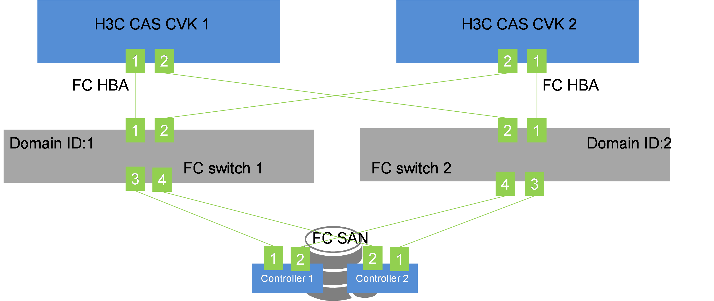
As a best practice, plan the storage network as follows when FC SAN is used:
· Connect the two ports on the FC HBA to different FC switches.
· Install a dual-port FC HBA on each controller of the FC SAN, and connect the two ports to different FC switches.
· Do not interconnect the two FC switches.
Figure 3 Storage network planning with FC SAN
An FC switch enables you to isolate devices by creating zones. Devices in the same zone can communicate, and devices in different zones cannot.
A zone supports domain/port, WWN, and alias members.
As a best practice, assign an HBA port on a server and an HBA port on an FC SAN controller to a zone, and create a zone for each of the HBA port pairs.
You can zone an FC switch based on WWNs or interface numbers. As a best practice, zone it based on WWNs.
FC switch zoning example
Table 6 WWNs of the FC HBAs
|
FC HBA location |
WWN |
|
|
FC HBA port 1 |
FC HBA port 2 |
|
|
H3C CAS CVK 1 |
50:01:43:80:24:d2:8a:aa |
50:01:43:80:24:d2:8a:ab |
|
H3C CAS CVK 2 |
50:01:43:80:24:d2:8b:ac |
50:01:43:80:24:d2:8b:ad |
|
FC SAN controller 1 |
50:01:43:80:24:d2:8c:aa |
50:01:43:80:24:d2:8c:ab |
|
FC SAN controller 2 |
50:01:43:80:24:d2:8c:ac |
50:01:43:80:24:d2:8c:ad |
To zone the FC switches based on WWNs:
1. Configure FC switch 1:
zonecreate "CVK01-01", "50:01:43:80:24:d2:8a:aa; 50:01:43:80:24:d2:8c:aa "
zonecreate "CVK01-02", "50:01:43:80:24:d2:8a:aa; 50:01:43:80:24:d2:8c:ac "
zonecreate "CVK02-01", "50:01:43:80:24:d2:8b:ad; 50:01:43:80:24:d2:8c:aa "
zonecreate "CVK02-02", "50:01:43:80:24:d2:8b:ad; 50:01:43:80:24:d2:8c:ac "
2. Configure FC switch 2:
zonecreate "CVK02-01", "50:01:43:80:24:d2:8b:ac; 50:01:43:80:24:d2:8c:ad "
zonecreate "CVK02-02", "50:01:43:80:24:d2:8b:ac; 50:01:43:80:24:d2:8c:ab "
zonecreate "CVK01-01", "50:01:43:80:24:d2:8a:ab; 50:01:43:80:24:d2:8c:ad "
zonecreate "CVK01-02", "50:01:43:80:24:d2:8a:ab; 50:01:43:80:24:d2:8c:ab "
To zone the FC switches based on interface numbers:
1. Configure FC switch 1:
zonecreate "CVK01-01", "1,1; 1,3"
zonecreate "CVK01-02", "1,1; 1,4"
zonecreate "CVK02-01", "1,2; 1,3"
zonecreate "CVK02-02", "1,2; 1,4"
2. Configure FC switch 2:
zonecreate "CVK02-01", "2,1; 2,3"
zonecreate "CVK02-02", "2,1; 2,4"
zonecreate "CVK01-01", "2,2; 2,3"
zonecreate "CVK01-02", "2,2; 2,4"
Planning local disks
As a best practice, set up RAID arrays on the disks of a server as follows:
· Set up a RAID 1 array if the server has only two disks.
· Set up RAID 5 arrays if the server has three or more disks.
Installing CAS
|
|
CAUTION: To avoid affecting services running on other hosts in the cluster, remove a host from the cluster before installing CAS if you reinstall the CVK component for that host. |
H3C CAS has two components CVK and CVM. On a management server, you must install all these two CAS components. On a virtualization server, you need to install only the CVK component.
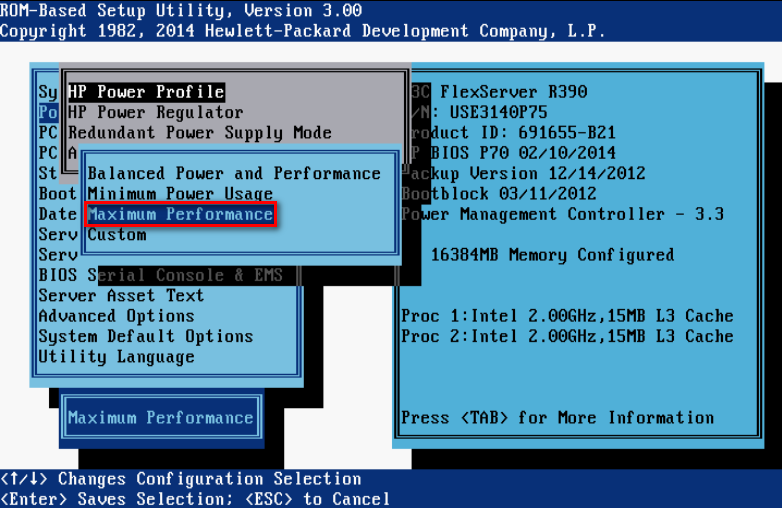
As a best practice to maximize server performance, configure a server to run with the maximum power. The configuration is as follows:
1. Select Power Management Options > HP Power Profile.
2. Select Maximum Performance.
Figure 4 Configuring maximum performance
Pre-installation configuration
Typically, a server provides built-in management software, through which you can install an operating system for the server.
Before installing CAS on a server, perform the following tasks on the server:
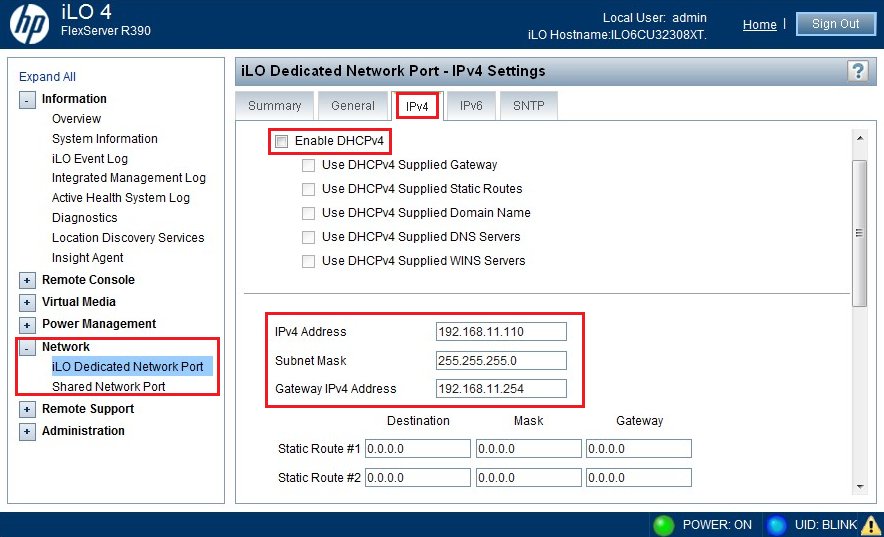
1. Configure the server management software such as iLO or IPMI.
Figure 5 Configuring server management software
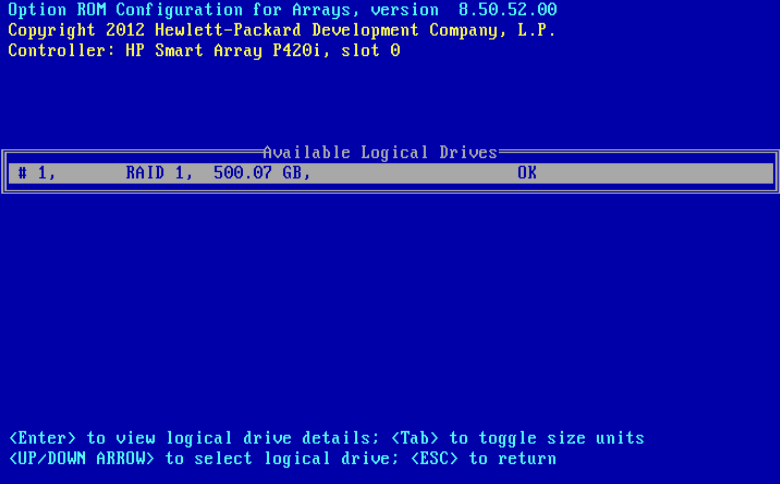
2. Set up RAID arrays on the disks of the server.
For configuration details, see the configuration guide for the server.
|
|
IMPORTANT: If you do not configure RAID arrays for the disks on a server, you cannot install an operating system for the server, because the disks on the server cannot be recognized. |
Figure 6 Configuring RAID arrays
3. Start the server and enter the BIOS setup utility.
4. Enable CPU virtualization features, and configure USB or CD-ROM as the first boot option as needed.
5. Save the BIOS settings and quit the BIOS setup utility.
For more information about BIOS settings, see the user manual that comes with the server.
6. Restart the server.
Performing installation tasks
Installation task list
|
Tasks at a glance |
|
(Required.) Starting the installation |
|
(Optional.) Configuring network parameters To configure IPv6 addresses, this step is required. |
|
(Required.) Selecting the system disk |
|
(Required.) Partitioning the disk Choose one of the following methods: |
|
(Required.) Setting the date, time, and time zone |
|
(Required.) Selecting the components to install |
|
(Required.) Selecting the components to install |
|
(Required.) Finishing the installation |
|
(Optional.) Changing network parameters after installation of CAS |
Starting the installation
|
|
IMPORTANT: You can install CAS by using a CD-ROM, a bootable USB drive, or the virtual drive on the server. Be aware of the following restrictions: · To prevent access failure to the CVM server after CAS installation, do not use UltraISO to build a bootable USB drive. · You can use Linux or Rufus DD mode to build a USB bootable flash drive. Rufus has multiple versions. Some versions do not support DD mode. As a best practice, use Linux DD to build a USB bootable flash drive. For information about building a bootable USB drive, see " Building a bootable USB drive." · When you use a CD-ROM to install CAS, the installation might be unstable depending on the CD-ROM burning quality. |
To start the installation:
1. Place the CD-ROM into the optical disk drive, mount the image file onto the virtual drive, or insert the USB bootable drive into the USB port on the server.
For an ARM server, use the following procedure to mount an ISO image file onto the virtual drive:
a. Launch the BMC Web console.
b. Select Media > Virtual Media Wizard.
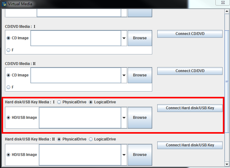
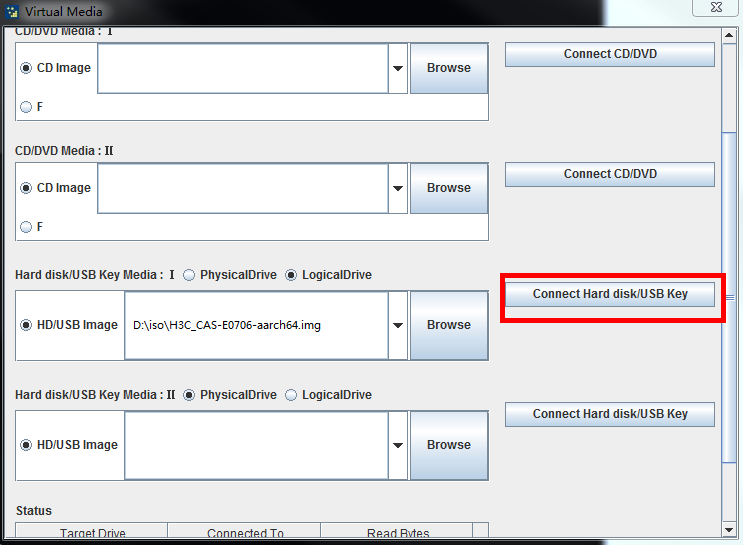
c. On the Virtual Media page, identify the Hard disk/USB Key Media : I area.
Figure 7 Identifying the Hard disk/USB Key Media : I area
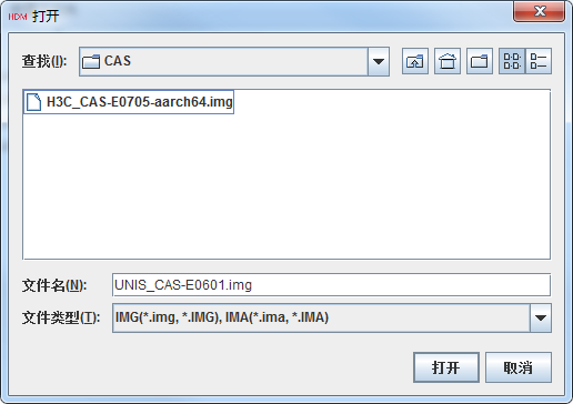
d. Click Browse and then select the ARM version of the CAS ISO image file.
Figure 8 Selecting the ARM version of the CAS ISO image file
e. Click Connect Hard disk/USB Key.
Figure 9 Connecting the hard disk or USB key
2. Start the server. Then, select to boot up from the CD-ROM or USB bootable drive. The CAS installation start page is displayed.
Figure 10 CAS installation start page
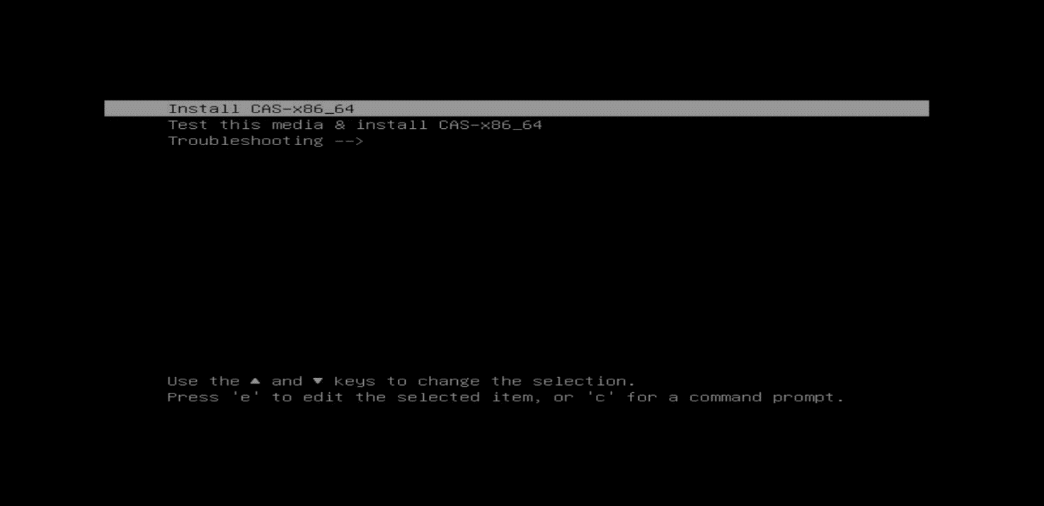
3. On the CAS installation start page, perform either of the following tasks:
a. For a server that is not Huawei 2488H V5 or 2288H V5 server, select install cas-X86_64 and then press Enter, or wait for the system to start installation automatically.
¡ For a Huawei 2488H V5 or 2288H V5 server, modify the installation parameters as follows and then press CTRL+X to start installation.
|
|
IMPORTANT: When installing CAS on a Huawei 2488H V5 or 2288H V5 server, a black screen might occur if you do not modify the installation parameters. If the same black screen error occurs on other server models, use the same procedure to fix it. |
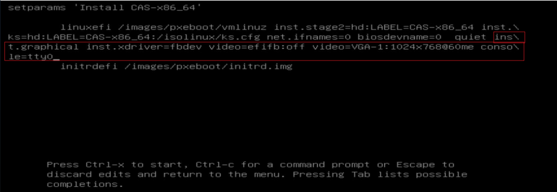
# Press E to enter edit mode.
# At the end of the line starting with linuxefi or linux, add inst.graphical inst.xdriver=fbdev video=efifb:off video=VGA-1:1024x768-32@60me ro console=tty0.
Figure 11 Adding parameters
Configuring network parameters
You can choose to configure the network parameters manually or not configure the network parameters during the installation process. If you do not configure network parameters during the installation process, DHCP is used by default and you must change the network parameters to static settings after installation. For more information, see "Changing network parameters after installation of CAS."
|
|
IMPORTANT: To use Disaster Recovery Management (DRM) or heterogeneous migration on CAS, plan the IP address for the management network interface in advance and configure it manually. |
To configure network parameters manually:
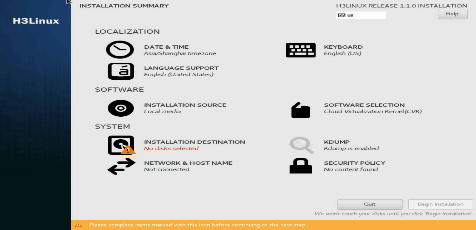
1. On the INSTALLATION SUMMARY page, click NETWORK & HOST NAME in the SYSTEM area.
Figure 12 INSTALLATION SUMMARY page
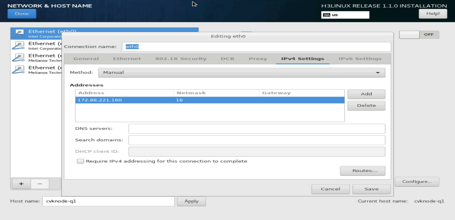
2. Select a NIC and click Configure in the bottom right corner. Then, select the manual method and configure the parameters, including the IP address, subnet mask, gateway IP address, DNS server IP address, and domain name.
|
|
IMPORTANT: To configure an IPv6 address, first disable the IPv4 address. |
Figure 13 Network settings
3. Set a host name for the server in the bottom left corner and then click Done.
As a best practice, specify a name that contains only letters and digits. A host name must meet the following requirements:
¡ It can contain only letters, digits, hyphens (-), and dots (.).
¡ It cannot start with a digit, hyphen (-), or dot (.) and end with a hyphen (-) or dot (.).
¡ The length cannot exceed 255 characters.
Selecting the system disk
1. On the INSTALLATION SUMMARY page, click INSTALLATION DESTINATION in the SYSTEM area.
Figure 14 INSTALLATION DESTINATION page
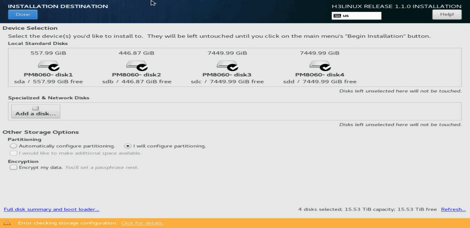
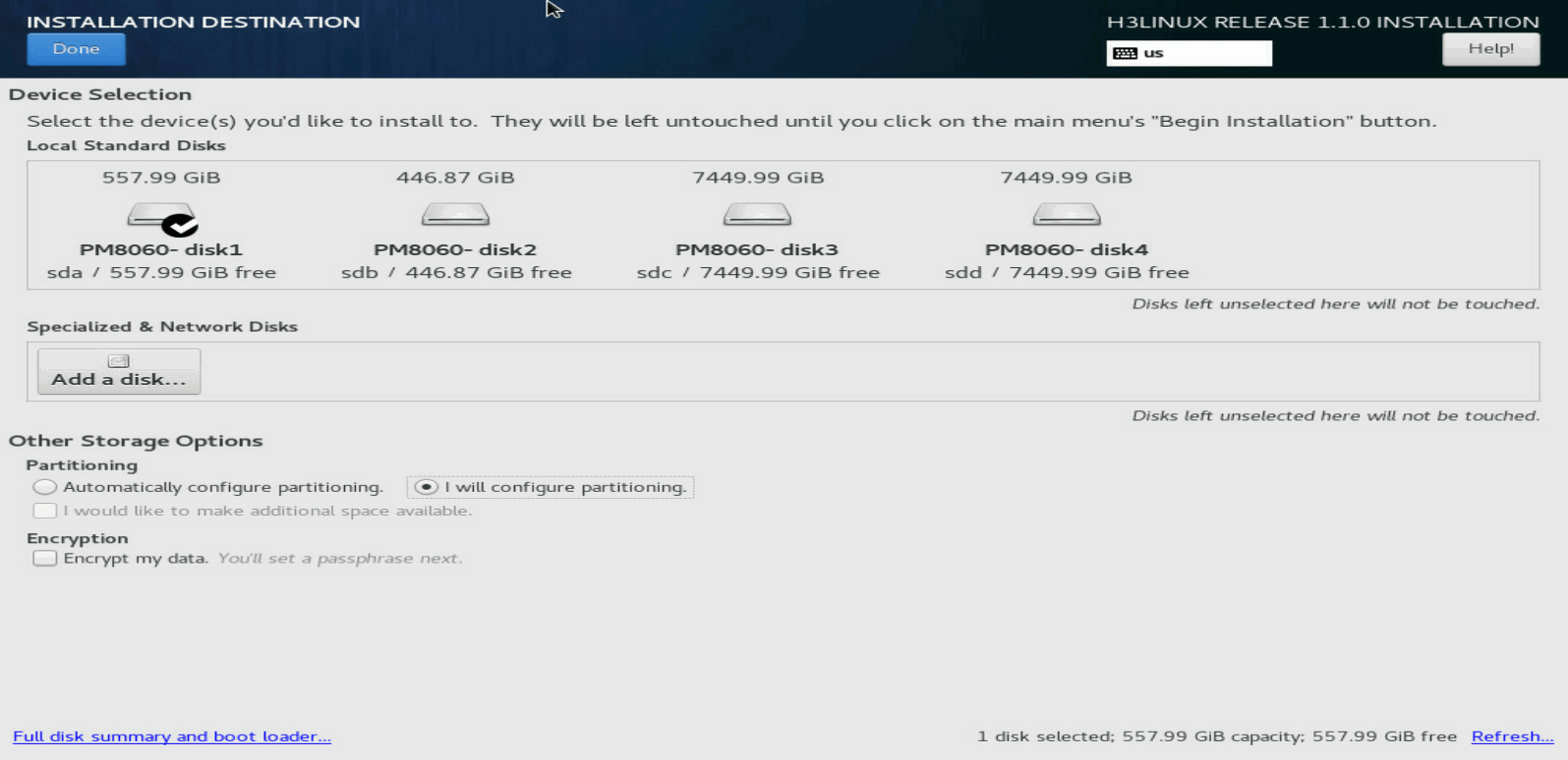
2. In the Local Standard Disks area, clear the disks on which you are not to install the system. Leave one disk selected to install the system.
Figure 15 Selecting the disk to install the system
Partitioning the disk
The disk to install CAS can be partitioned automatically or manually. As a best practice, use automatic partitioning if no system is installed on the disk.
|
|
IMPORTANT: · To partition the disk automatically, make sure the disk space is larger than or equal to 120 GiB. · If a system has been installed on the disk, select manual partitioning and then delete the system before partitioning the disk. |
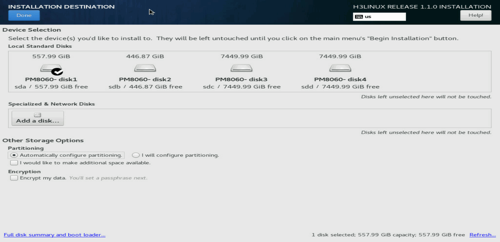
Automatic disk partitioning
1. On the INSTALLATION DESTINATION page, select Automatically configure partitioning in the Partitioning area.
Figure 16 Selecting automatic disk partitioning
2. Click Done in the top left corner.
The system returns to the INSTALLATION SUMMARY page when the partitioning is complete.
Figure 17 Returning to the INSTALLATION SUMMARY page

Manual disk partitioning
1. On the INSTALLATION DESTINATION page, select I will configure partitioning in the Partitioning area. Then click Done in the top left corner.
Figure 18 Selecting manual disk partitioning

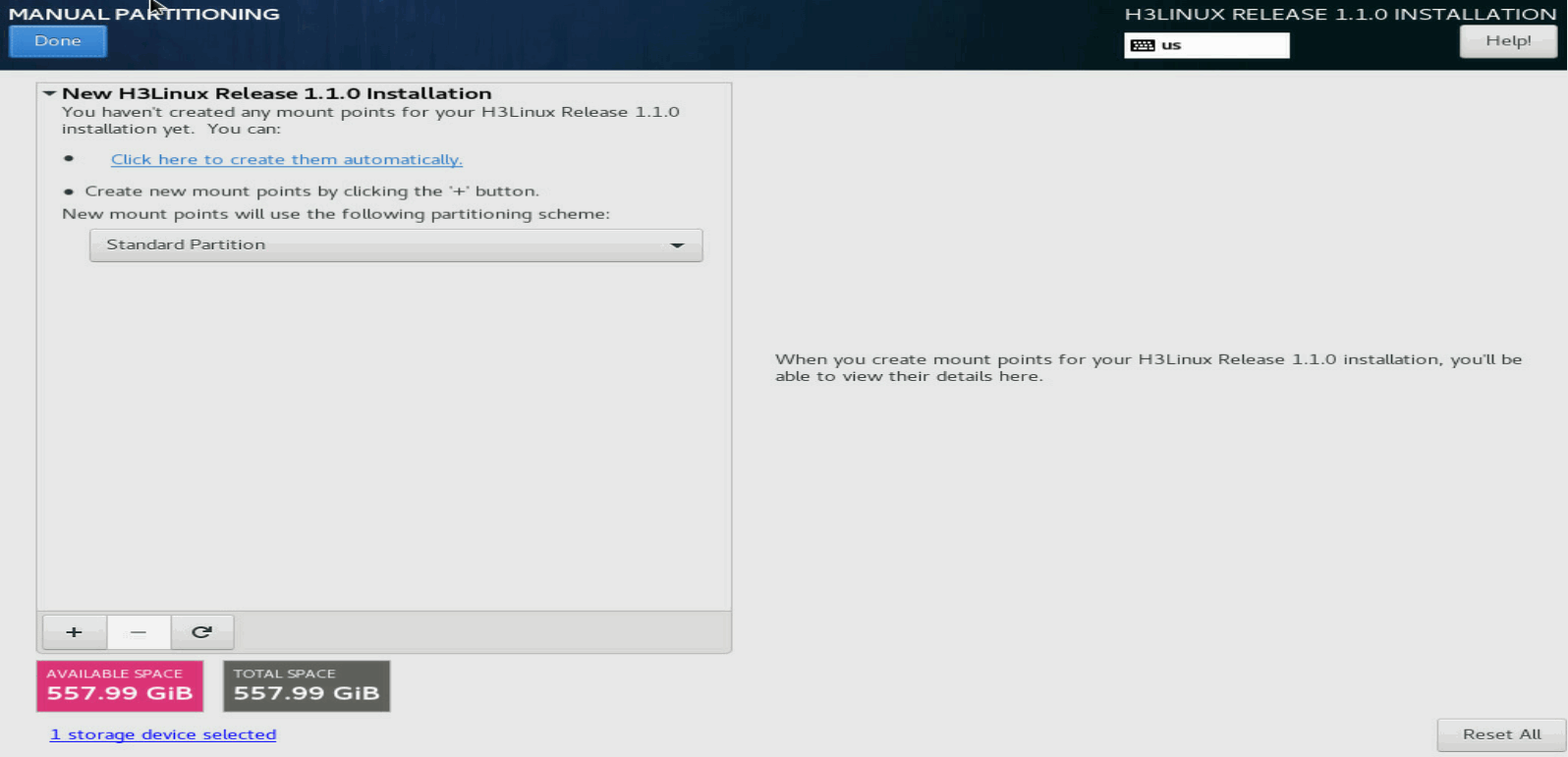
2. On the MANUAL PARTITIONING page, click the ![]() button.
button.
Figure 19 MANUAL PARTITIONING page
|
|
NOTE: If a system has been installed on the disk, delete the system as follows: # Select an old partition and click the # In the dialog box that opens, select the Delete all file systems which are only used by CentOS Linux 7.6.18.10 for x86_64. option, and then click Delete it to delete all old partitions. If you do not select this option, you must delete the old partitions one by one. |
3. In the dialog box that opens, select a partition from the Mount Point list and set a capacity for it. Then click Add mount point.
¡ If the server has booted in UEFI boot mode, add /boot/efi, /boot, /, /var/log, swap, and /vms partitions in turn. See Table 7 for the partition specifications.
¡ If the server has booted in Legacy boot mode, add /, /boot, /var/log, swap, and /vms partitions in turn. See Table 7 for the partition specifications.
Figure 20 Adding a new mount point
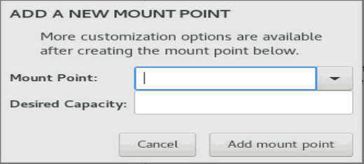
Figure 21 shows sample partitioning information when the partitioning is complete.
Figure 21 Partitioning information
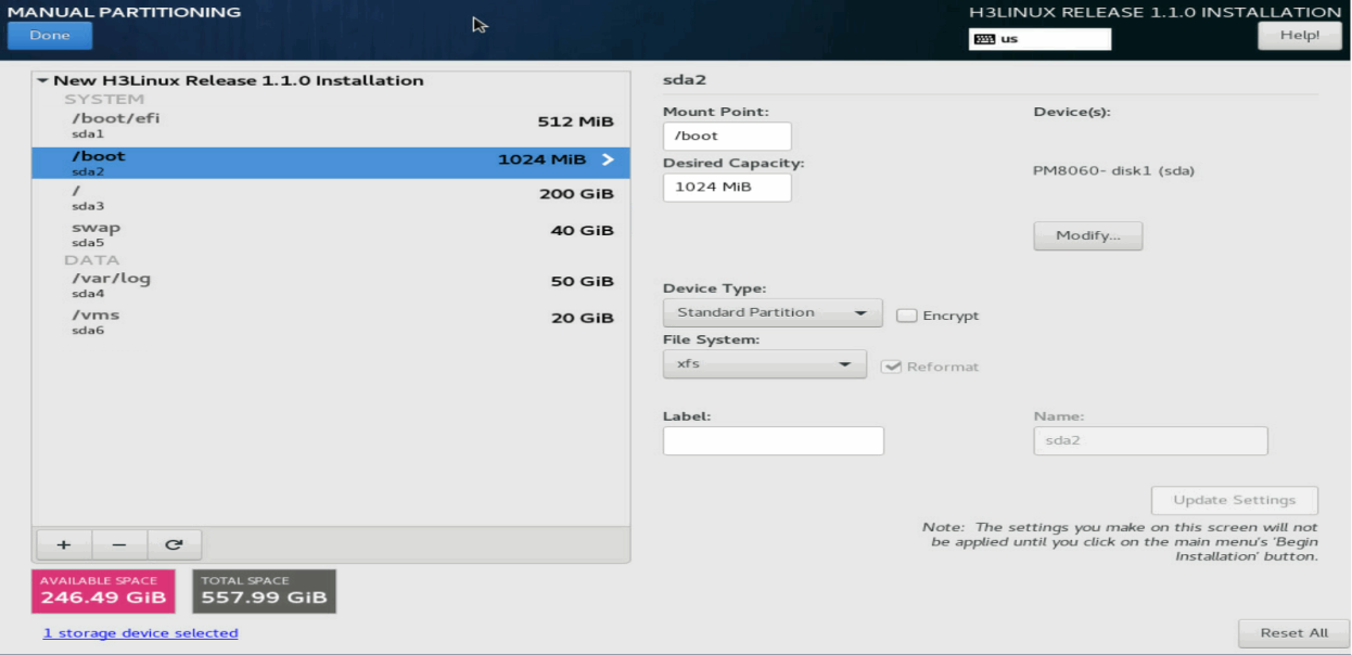
Table 7 Partition descriptions and specifications
|
Partition |
Description |
File system |
Min. size (MiB) |
Recommended size (MiB) |
|
/boot/efi (bootstrap partition) |
Stores boot files of the system. |
EFI System Partition |
200 |
200 |
|
/boot (boot partition) |
Stores the files for booting the system kernel. |
ext4 (recommended) |
1024 |
1024 |
|
/ (root partition) |
Stores all directories of the system. Users can access all directories from this partition. |
ext4 (recommended) |
102400 |
204800 |
|
/var/log (log partition) |
Stores log files about system operations. |
ext4 (recommended) |
10240 |
40960 |
|
swap (swap partition) |
Stores temporary data when the system memory is insufficient. After a period of time, the system will transfer the temporary data into the memory for execution. This partition can be accessed only by the system. |
swap |
30GiB |
30GiB |
|
/vms (VM data partition) |
Stores all data files of VMs. |
ext4 |
· Standalone:1024 · Stateful failover: 30GiB |
No limited. As a best practice, allocate a largest possible space to the /vms partition while ensuring sufficient space for other partitions. |
|
|
IMPORTANT: The database partition for stateful failover is created in the /vms partition and the /vms partition itself requires a size of space. Please make sure the /vms partition is the last partition. As a best practice, allocate a largest possible space to the /vms partition while ensuring sufficient space for other partitions. Use this formula to estimate the minimum size for the /vms partition: database partition size (number of hosts*10 MB + number of VMs*15 MB)*15/1024 MB + 10GB. If the estimated value is smaller than 30 GB, allocate a minimum of 30 GB to the partition. If the estimated value is larger than 30 GB, allocate a size equal to or larger than the estimated size to the partition. |
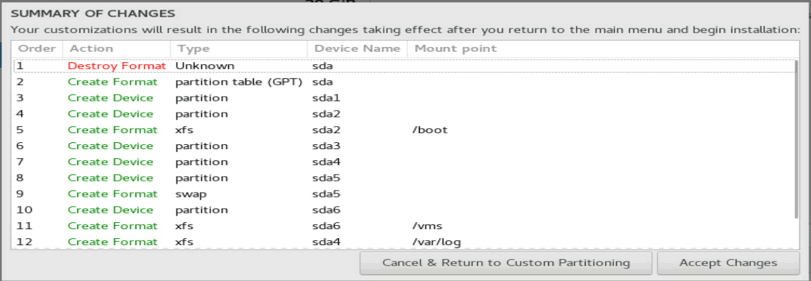
4. Click Done in the top left corner.
5. In the dialog box that opens, click Accept Changes to confirm the partitioning.
Figure 22 Confirming the partitioning
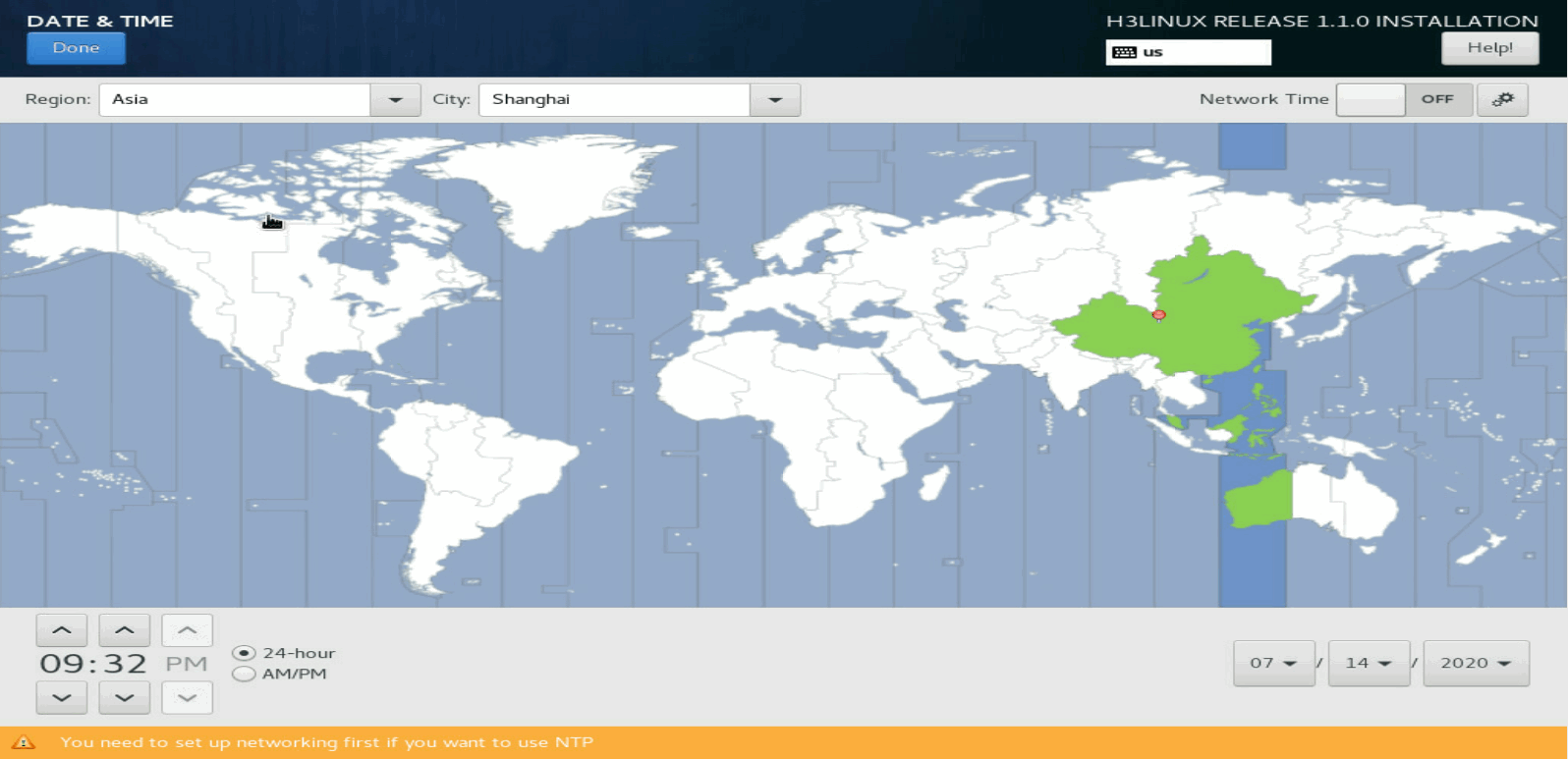
Setting the date, time, and time zone
On the INSTALLATION SUMMARY page, click DATE & TIME. Then set a correct date, time, and time zone for the system.
Figure 23 Setting the date, time, and time zone
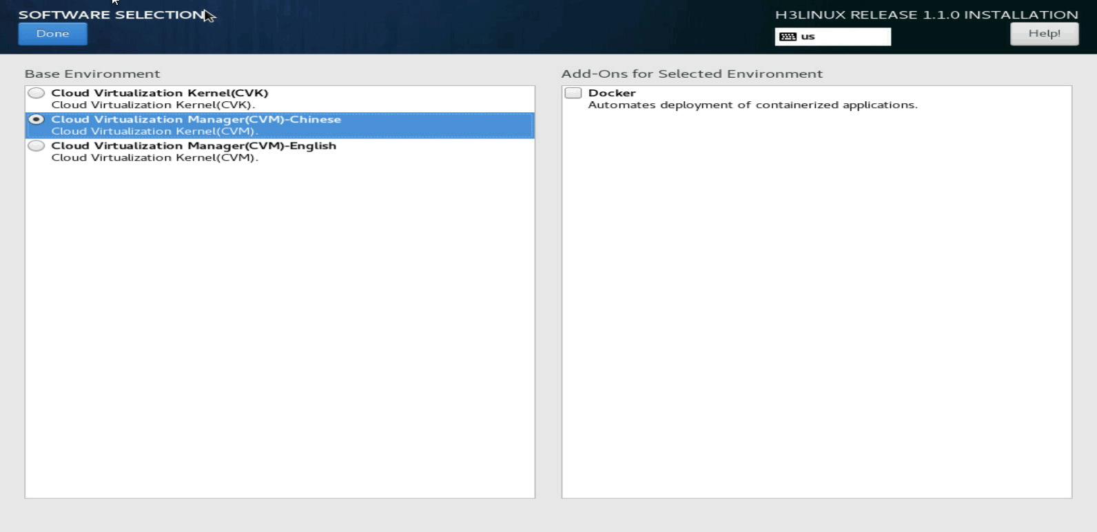
Selecting the components to install
On the SOFTWARE SELECTION page, select the components to install:
· For a management server, select CVM-English.
· For a virtualization server, select CVK.
Docker is a component in the H3Linux installation package. It does not affect installation of CAS. By default, Docker is not installed.
Figure 24 Selecting the components to install
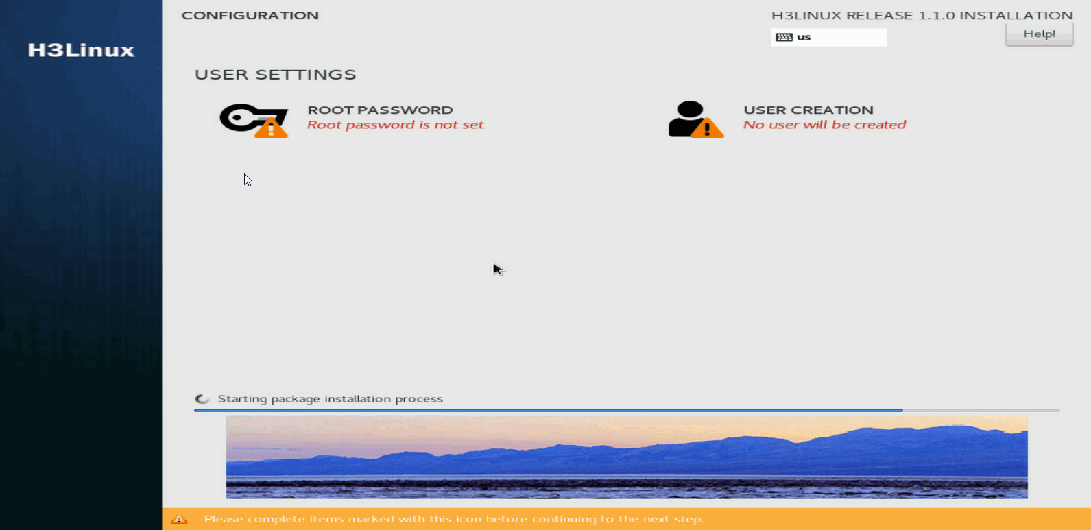
Finishing the installation
1. On the INSTALLATION SUMMARY page, click Begin installation.
2. Set a root password when prompted.
The system creates the sysadmin account with default password Sys@1234 after installation. You can use the sysadmin account to perform operations such as adding hosts after you disable Root SSH on the management platform.
Figure 25 Setting a root password
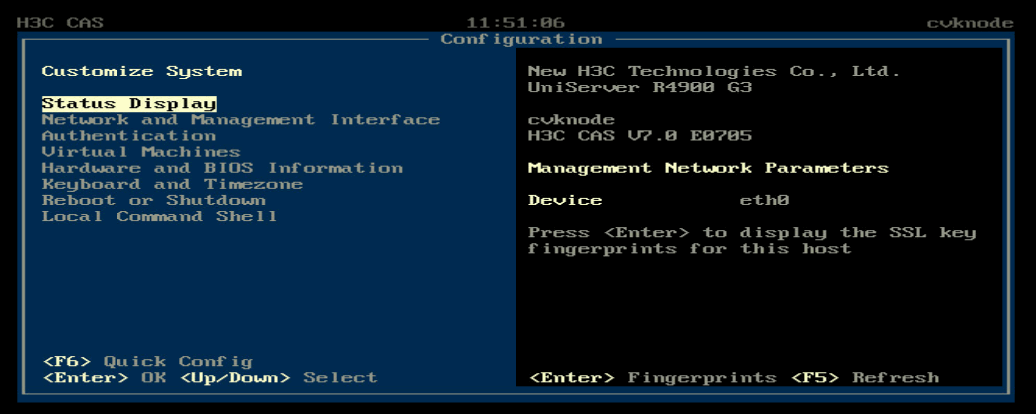
After the installation is complete, the host restarts automatically and opens the Configuration screen.
Before the reboot is completed, eject the CD-ROM, disconnect the virtual drive, or unplug the USB flash drive.
|
|
CAUTION: As a best practice, unplug the USB flash drive before the system is started. If the server is started with a USB flash drive installed, check the system disk name. If the system disk name is /sdb (the system disk name is /sda in normal conditions), unplug the USB flash drive and then restart the server. This prevents CVM from recording an incorrect system disk name in the stateful failover configuration file during the stateful failover setup process. |
Figure 26 Host configuration screen
|
|
NOTE: The network parameter settings, if not configured manually during the installation process, depend on whether a DHCP server is available: · If a DHCP server exists in the management network, the host obtains an IP address from the DHCP server automatically. · If no DHCP server exists in the management network, all management network parameters on the Configuration screen are empty. |
Changing network parameters after installation of CAS
To change network parameters configured during the installation process, access the server console for the change after installation.
|
|
IMPORTANT: You can choose to configure the network parameters manually or not configure the network parameters during the installation process. If you do not configure network parameters during the installation process, DHCP is used by default and you must change the network parameters to static settings after installation. |
To change network parameters after installation of CAS:
1. Access the console of the server and then access the Configuration screen.
Figure 27 Configuration screen

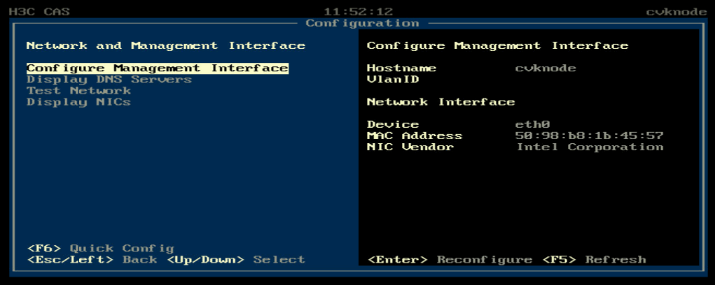
2. Select Network and Management Interface > Configure Management Interface.
Figure 28 Configure Management Interface screen
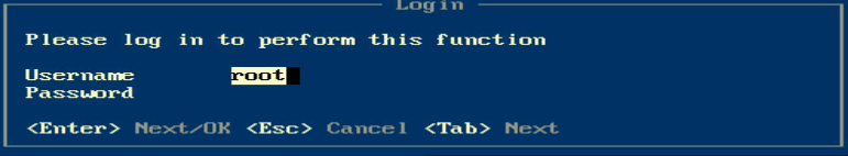
3. Enter the password of the root user. By default, the password is root.
Figure 29 Login screen
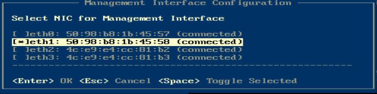
4. Select a management network interface and then press Enter.
|
|
IMPORTANT: Select two NICs if link aggregation has been configured for the management network. |
Figure 30 Selecting a NIC
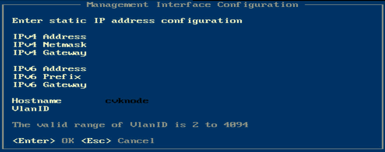
5. Enter the IP address, subnet mask, gateway address, hostname, and VLAN ID for the management interface as needed, and then press Enter.
For hostname requirements, see "Configuring network parameters."
Figure 31 Configuring management interface parameters
Setting the system time for each server
After CAS is installed on a server, the server will restart and automatically enter the CAS console. Set the system time for each server at the console to ensure consistent time among all servers.
Table 8 describes the commands for setting the system time.
Table 8 Commands for setting the system time
|
Command |
Description |
|
date xxxxxxxxxx |
Set the system time in the MMDDHHMMYY format. For example, to set the time to 14: 29, September 30th, 2012, enter date 0930142912. |
|
hwclock -w |
Write the time to the BIOS. |
Configuring link aggregation for the management network
After CAS installation, you can configure link aggregation for the management network on the xsconsole page. To configure link aggregation, you must select multiple physical NICs (interfaces) for the host.
· You can configure static or dynamic link aggregation for the interfaces as required. To configure dynamic link aggregation, you must enable LACP on the physical switch.
· You can configure basic, advanced, or active/standby load balancing for the interfaces as required.
¡ Advanced load balancing—Distributes traffic across the interfaces based on Ethernet type, IP protocol, source IP address, destination IP address, source port, and destination port.
¡ Basic load balancing—Distributes traffic across the interfaces based on the source MAC address and VLAN tag.
¡ Active/standby load balancing—Distributes traffic based on the primary and backup roles of the interfaces. When the primary interface fails, traffic is automatically switched to the backup interfaces. Dynamic link aggregation does not support this mode.
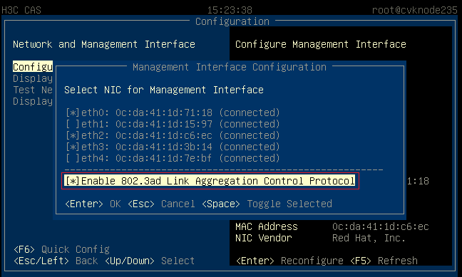
Configuring dynamic link aggregation
1. On the Management Interface Configuration page, select multiple NICs and enable LACP.
Figure 32 Configuring dynamic link aggregation
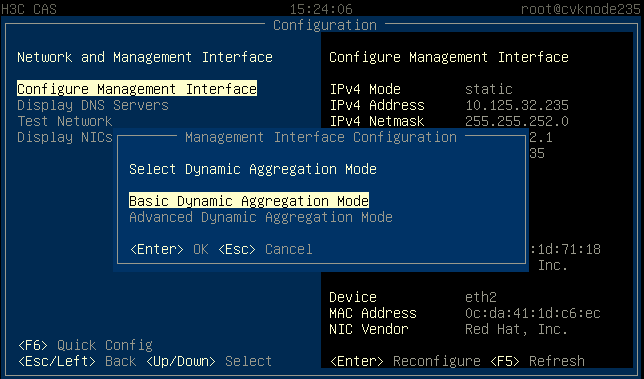
2. Select basic or advanced load balancing mode as required.
Figure 33 Configuring the load balancing mode
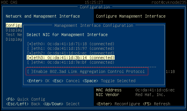
Configuring static link aggregation
1. On the Management Interface Configuration page, select multiple NICs and leave LACP unselected.
Figure 34 Configuring static link aggregation
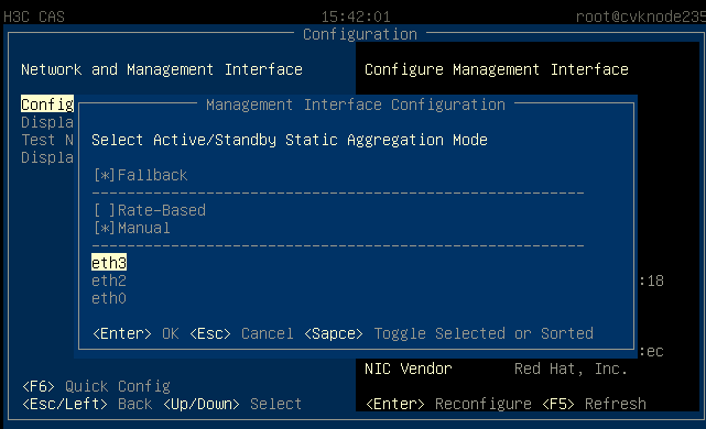
2. Select basic, advanced, or active/standby load balancing mode as required.
Figure 35 Configuring the load balancing mode

3. (Optional.) Specify the priority for the primary and backup interfaces if active/standby load balancing mode is configured.
Figure 36 Specifying the priority for the primary and backup interfaces
Accessing CAS
You can access CAS through HTTP or HTTPS.
Accessing CVM
To access CVM:
1. Launch your web browser such as Google Chrome or Mozilla Firefox.
2. Enter http:// server-ip:8080/cas or https:// server-ip:8443/cas in the address bar of the Web browser.
The IP address must be that of the management network interface configured for the management server.
3. Enter the username and password.
Both the default username and password are admin and Cloud@1234, respectively.
|
|
IMPORTANT: As a best practice, change your password at the first login and keep the new password safe. |
Accessing CIC
1. Launch your web browser such as Google Chrome or Mozilla Firefox.
2. Enter http://server-ip:8080/cic or https://server-ip:8443/cic in the address bar of the Web browser.
The IP address must be that of the management network interface configured for the management server.
3. Enter the username and password.
Both the default username and password are admin and Cloud@1234, respectively.
|
|
IMPORTANT: As a best practice, change your password at the first login and keep the new password safe. |
Accessing SSV
1. Launch your web browser such as Google Chrome or Mozilla Firefox.
2. Enter http://server-ip:8080/ssv or https://server-ip:8443/ssv in the address bar of the Web browser.
The IP address must be that of the management network interface configured for the management server.
3. Enter the username and password.
The username and password are set in CIC by the operator.
FAQs
What browsers can I use to access CAS?
As a best practice, use browser Google Chrome 39, or Mozilla Firefox 22 to access CAS.
Do I need to install a client for accessing CAS?
No. CAS uses the browser/server (B/S) architecture and you can access CAS directly by using a browser.
To access CAS, enter http://server-ip or https://server-ip in the address bar of a Web browser. The IP address must be that of the management interface configured for the management server.
Why do some pages look different when they are accessed from different browsers?
This is because the browsers interpret some page elements differently. This issue is normal and does not affect the functionality of the product.
What installation media can I use to install CAS?
As a best practice, use a USB drive or virtual drive to install CAS.
Appendix Building a bootable USB drive
You can build a bootable USB drive by burning an ISO image file to the USB drive, and use the bootable USB drive to install software for the server.
You can use Linux or Rufus DD mode to build a USB bootable flash drive. Rufus has multiple versions. Some versions do not support DD mode. As a best practice, use Linux DD to build a USB bootable flash drive.
Using Linux DD mode to build a USB bootable flash drive
1. Prepare for the building.
a. Insert a USB flash drive into a device running a Linux operating system.
b. Copy the ISO image file to the Linux system.
Execute the md5sum xx.iso command (xx.iso is the file name) before and after the copying operation to verify the integrity of the copied file.
c. Execute the fdisk -l command to view the name of the USB flash drive. This procedure uses name sdb as an example.
2. Execute the mount | grep sdb command. Use /dev/sdb as an example.
¡ If this command displays mounting information for the USB flash drive, the drive has been automatically mounted to the Linux system. You must first unmount it and then mount it.
[root@cvknode-32 ~]# mount | grep sdb
/dev/sdb1 on /var/ftp type ext4 (rw,relatime,stripe=64,data=ordered)
[root@cvknode-32 ~]# umount /dev/sdb1
[root@cvknode-32 ~]# mount | grep sdb
¡ If no output is displayed, go to the next step.
3. Execute the dd if= xx.iso of=/dev//USB flash drive name bs=1M command to burn the ISO image file onto the USB flash drive.
4. Execute the sync && sync command.
5. Remove the USB flash drive from the device.
Using Rufus to build a USB bootable flash drive
Rufus is a free bootable drive building tool that can be downloaded from its official website.
To build a bootable USB drive, perform steps 1 and 2 for a Ubuntu ISO image file and steps 1 to 4 for a CentOS ISO image file.
1. Double-click the Rufus tool. On the Rufus window, select the target USB drive from the Device list and Disk or ISO image (Please select) from the Boot selection list and then click SELECT.
Figure 37 Selecting the USB drive and ISO image booting

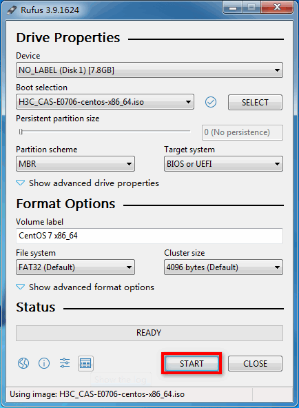
2. Select the H3C CAS ISO image file, for example, H3C_CAS-E0706-centos-x86.iso and configure the other settings as required. Then click START.
Figure 38 Starting to build the bootable USB flash drive
3. On the ISOHybrid image detected window, select Write in DD image mode and then click OK.
Figure 39 Selecting to write in DD image node
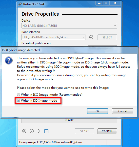
Figure 40 Building the bootable USB flash drive

