- Table of Contents
- Related Documents
-
| Title | Size | Download |
|---|---|---|
| 07-Monitor Link configuration | 109.26 KB |
Contents
Restrictions and guidelines: Monitor Link configuration
Monitor Link tasks at a glance
Enabling Monitor Link globally
Configuring monitor link group member interfaces
Configuring monitor link group member interfaces in monitor link group view
Configuring monitor link group member interfaces in interface view
Configuring the uplink interface threshold for triggering monitor link group state switchover
Configuring the switchover delay for the downlink interfaces in a monitor link group
Display and maintenance commands for Monitor Link
Configuring Monitor Link
About Monitor Link
Monitor Link associates the state of downlink interfaces with the state of uplink interfaces in a monitor link group. When Monitor Link shuts down the downlink interfaces because of an uplink failure, the downstream device changes connectivity to another link.
Figure 1 Monitor Link application scenario
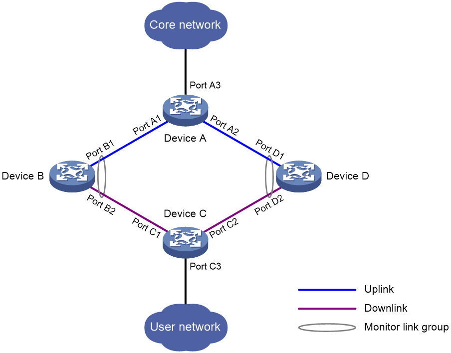
A monitor link group contains uplink and downlink interfaces. An interface can belong to only one monitor link group.
· Uplink interfaces are the monitored interfaces.
· Downlink interfaces are the monitoring interfaces.
As shown in Figure 1:
· Port B1 and Port B2 of Device B form a monitor link group. Port B1 is an uplink interface, and Port B2 is a downlink interface.
· Port D1 and Port D2 of Device D form another monitor link group. Port D1 is an uplink interface, and Port D2 is a downlink interface.
A monitor link group works independently of other monitor link groups. When a monitor link group does not contain any uplink interface or all its uplink interfaces are down, the monitor link group goes down. It forces all downlink interfaces down at the same time. When any uplink interface comes up, the monitor link group comes up and brings up all the downlink interfaces.
Restrictions and guidelines: Monitor Link configuration
Follow these restrictions and guidelines when you configure Monitor Link:
· Do not manually shut down or bring up the downlink interfaces in a monitor link group.
· To avoid frequent state changes of downlink interfaces in the event that uplink interfaces in the monitor link group flap, you can configure a switchover delay. The switchover delay is the time that the downlink interfaces wait before they come up following an uplink interface.
Monitor Link tasks at a glance
To configure Monitor Link, perform the following tasks:
· Enabling Monitor Link globally
· Creating a monitor link group
· Configuring monitor link group member interfaces
· (Optional.) Configuring the uplink interface threshold for triggering monitor link group state switchover
· (Optional.) Configuring the switchover delay for the downlink interfaces in a monitor link group
Enabling Monitor Link globally
About enabling Monitor Link globally
All monitor link groups can operate only after you enable Monitor Link globally. When you disable Monitor Link globally, all monitor link groups cannot operate and the downlink interfaces brought down by the monitor link groups resume their original states.
Procedure
1. Enter system view.
system-view
2. Enable Monitor Link globally.
undo monitor-link disable
By default, Monitor Link is enabled globally.
Creating a monitor link group
1. Enter system view.
system-view
2. Create a monitor link group and enter monitor link group view.
monitor-link group group-id
Configuring monitor link group member interfaces
Restrictions and guidelines
· An interface can be assigned to only one monitor link group.
· To avoid undesired down/up state changes on the downlink interfaces, configure uplink interfaces before you configure downlink interfaces.
· If you have configured a Selected port of an aggregation group as the downlink interface of a monitor link group, do not configure an Unselected port of the aggregation group as the uplink interface of the monitor link group.
· Do not add an aggregate interface and its member ports to the same monitor link group.
· You can configure member interfaces for a monitor link group in monitor link group view or interface view. Configurations made in these views have the same effect. The configuration is supported by the following interfaces:
¡ Layer 2 Ethernet interfaces.
¡ Layer 2 aggregate interfaces.
Configuring monitor link group member interfaces in monitor link group view
1. Enter system view.
system-view
2. Enter monitor link group view.
monitor-link group group-id
3. Configure member interfaces for the monitor link group.
port interface-type interface-number { downlink | uplink }
By default, no member interfaces exist in a monitor link group.
Configuring monitor link group member interfaces in interface view
1. Enter system view.
system-view
2. Enter interface view.
interface interface-type interface-number
3. Configure the interface as a member of a monitor link group.
port monitor-link group group-id { downlink | uplink }
By default, the interface is not a monitor link group member.
Configuring the uplink interface threshold for triggering monitor link group state switchover
1. Enter system view.
system-view
2. Enter monitor link group view.
monitor-link group group-id
3. Configure the uplink interface threshold for triggering monitor link group state switchover.
uplink up-port-threshold number-of-port
By default, the uplink interface threshold for triggering monitor link group state switchover is 1.
Configuring the switchover delay for the downlink interfaces in a monitor link group
1. Enter system view.
system-view
2. Enter monitor link group view.
monitor-link group group-id
3. Configure the switchover delay for the downlink interfaces in the monitor link group.
downlink up-delay delay
By default, the switchover delay is 0 seconds. The downlink interfaces come up as soon as an uplink interface comes up.
Display and maintenance commands for Monitor Link
Execute the display command in any view:
|
Task |
Command |
|
Display monitor link group information. |
display monitor-link group { group-id | all } |
Monitor Link configuration examples
Example: Configuring Monitor Link
Network configuration
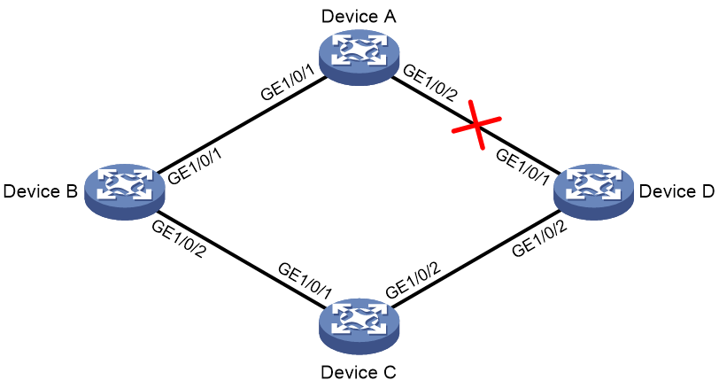
As shown in Figure 2:
· Device C is a Smart Link device, and Device A, Device B, and Device D are associated devices. Traffic of VLANs 1 through 30 on Device C is dual-uplinked to Device A through a smart link group.
· Implement dual uplink backup on Device C. When the link between Device A and Device B (or Device D) fails, Device C can detect the link fault. It then performs uplink switchover in the smart link group.
For more information about Smart Link, see "Configuring Smart Link."
Procedure
1. Configure Device C:
# Create VLANs 1 through 30.
<DeviceC> system-view
[DeviceC] vlan 1 to 30
# Map these VLANs to MSTI 1.
[DeviceC] stp region-configuration
[DeviceC-mst-region] instance 1 vlan 1 to 30
# Activate MST region configuration.
[DeviceC-mst-region] active region-configuration
[DeviceC-mst-region] quit
# Shut down GigabitEthernet 1/0/1.
[DeviceC] interface gigabitethernet 1/0/1
[DeviceC-GigabitEthernet1/0/1] shutdown
# Disable the spanning tree feature on the interface.
[DeviceC-GigabitEthernet1/0/1] undo stp enable
# Configure the interface as a trunk port.
[DeviceC-GigabitEthernet1/0/1] port link-type trunk
# Assign the interface to VLANs 1 through 30.
[DeviceC-GigabitEthernet1/0/1] port trunk permit vlan 1 to 30
[DeviceC-GigabitEthernet1/0/1] quit
# Configure GigabitEthernet 1/0/2 in the same way GigabitEthernet 1/0/1 is configured.
[DeviceC] interface gigabitethernet 1/0/2
[DeviceC-GigabitEthernet1/0/2] shutdown
[DeviceC-GigabitEthernet1/0/2] undo stp enable
[DeviceC-GigabitEthernet1/0/2] port link-type trunk
[DeviceC-GigabitEthernet1/0/2] port trunk permit vlan 1 to 30
[DeviceC-GigabitEthernet1/0/2] quit
# Create smart link group 1, and configure all the VLANs mapped to MSTI 1 as the protected VLANs for smart link group 1.
[DeviceC] smart-link group 1
[DeviceC-smlk-group1] protected-vlan reference-instance 1
# Configure GigabitEthernet 1/0/1 as the primary port and GigabitEthernet 1/0/2 as the secondary port for smart link group 1.
[DeviceC-smlk-group1] port gigabitethernet 1/0/1 primary
[DeviceC-smlk-group1] port gigabitethernet 1/0/2 secondary
# Enable the smart link group to transmit flush messages.
[DeviceC-smlk-group1] flush enable
[DeviceC-smlk-group1] quit
# Bring up GigabitEthernet 1/0/1 and GigabitEthernet 1/0/2.
[DeviceC] interface gigabitethernet 1/0/1
[DeviceC-GigabitEthernet1/0/1] undo shutdown
[DeviceC-GigabitEthernet1/0/1] quit
[DeviceC] interface gigabitethernet 1/0/2
[DeviceC-GigabitEthernet1/0/2] undo shutdown
[DeviceC-GigabitEthernet1/0/2] quit
2. Configure Device A:
# Create VLANs 1 through 30.
<DeviceA> system-view
[DeviceA] vlan 1 to 30
# Configure GigabitEthernet 1/0/1 as a trunk port.
[DeviceA] interface gigabitethernet 1/0/1
[DeviceA-GigabitEthernet1/0/1] port link-type trunk
# Assign the interface to VLANs 1 through 30.
[DeviceA-GigabitEthernet1/0/1] port trunk permit vlan 1 to 30
# Enable flush message receiving on the interface.
[DeviceA-GigabitEthernet1/0/1] smart-link flush enable
[DeviceA-GigabitEthernet1/0/1] quit
# Configure GigabitEthernet 1/0/2 in the same way GigabitEthernet 1/0/1 is configured.
[DeviceA] interface gigabitethernet 1/0/2
[DeviceA-GigabitEthernet1/0/2] port link-type trunk
[DeviceA-GigabitEthernet1/0/2] port trunk permit vlan 1 to 30
[DeviceA-GigabitEthernet1/0/2] smart-link flush enable
[DeviceA-GigabitEthernet1/0/2] quit
3. Configure Device B:
# Create VLANs 1 through 30.
<DeviceB> system-view
[DeviceB] vlan 1 to 30
# Configure GigabitEthernet 1/0/1 as a trunk port.
[DeviceB] interface gigabitethernet 1/0/1
[DeviceB-GigabitEthernet1/0/1] port link-type trunk
# Assign the interface to VLANs 1 through 30.
[DeviceB-GigabitEthernet1/0/1] port trunk permit vlan 1 to 30
# Enable flush message receiving on the interface.
[DeviceB-GigabitEthernet1/0/1] smart-link flush enable
[DeviceB-GigabitEthernet1/0/1] quit
# Disable the spanning tree feature on GigabitEthernet 1/0/2.
[DeviceB] interface gigabitethernet 1/0/2
[DeviceB-GigabitEthernet1/0/2] undo stp enable
# Configure the interface as a trunk port.
[DeviceB-GigabitEthernet1/0/2] port link-type trunk
# Assign the interface to VLANs 1 through 30.
[DeviceB-GigabitEthernet1/0/2] port trunk permit vlan 1 to 30
# Enable flush message receiving on the interface.
[DeviceB-GigabitEthernet1/0/2] smart-link flush enable
[DeviceB-GigabitEthernet1/0/2] quit
# Create monitor link group 1.
[DeviceB] monitor-link group 1
# Configure GigabitEthernet 1/0/1 as an uplink interface for monitor link group 1.
[DeviceB-mtlk-group1] port gigabitethernet 1/0/1 uplink
# Configure GigabitEthernet 1/0/2 as a downlink interface for monitor link group 1.
[DeviceB-mtlk-group1] port gigabitethernet 1/0/2 downlink
[DeviceB-mtlk-group1] quit
4. Configure Device D:
# Create VLANs 1 through 30.
<DeviceD> system-view
[DeviceD] vlan 1 to 30
# Configure GigabitEthernet 1/0/1 as a trunk port.
[DeviceD] interface gigabitethernet 1/0/1
[DeviceD-GigabitEthernet1/0/1] port link-type trunk
# Assign the interface to VLANs 1 through 30.
[DeviceD-GigabitEthernet1/0/1] port trunk permit vlan 1 to 30
# Enable flush message receiving on the interface.
[DeviceD-GigabitEthernet1/0/1] smart-link flush enable
[DeviceD-GigabitEthernet1/0/1] quit
# Disable the spanning tree feature on GigabitEthernet 1/0/2.
[DeviceD] interface gigabitethernet 1/0/2
[DeviceD-GigabitEthernet1/0/2] undo stp enable
# Configure the interface as a trunk port.
[DeviceD-GigabitEthernet1/0/2] port link-type trunk
# Assign the interface to VLANs 1 through 30.
[DeviceD-GigabitEthernet1/0/2] port trunk permit vlan 1 to 30
# Enable flush message receiving on the interface.
[DeviceD-GigabitEthernet1/0/2] smart-link flush enable
[DeviceD-GigabitEthernet1/0/2] quit
# Create monitor link group 1.
[DeviceD] monitor-link group 1
# Configure GigabitEthernet 1/0/1 as an uplink interface for monitor link group 1.
[DeviceD-mtlk-group1] port gigabitethernet 1/0/1 uplink
# Configure GigabitEthernet 1/0/2 as a downlink interface for monitor link group 1.
[DeviceD-mtlk-group1] port gigabitethernet 1/0/2 downlink
[DeviceD-mtlk-group1] quit
Verifying the configuration
# When GigabitEthernet 1/0/2 on Device A goes down because of a link fault, verify information about monitor link group 1 on Device B.
[DeviceB] display monitor-link group 1
Monitor link group 1 information:
Group status : UP
Downlink up-delay: 0(s)
Last-up-time : 16:38:26 2012/4/21
Last-down-time : 16:37:20 2012/4/21
Up-port-threshold: 1
Member Role Status
------------------------------------------------
GE1/0/1 UPLINK UP
GE1/0/2 DOWNLINK UP
# Verify information about monitor link group 1 on Device D.
[DeviceD] display monitor-link group 1
Monitor link group 1 information:
Group status : DOWN
Downlink up-delay: 0(s)
Last-up-time : 16:37:20 2012/4/21
Last-down-time : 16:38:26 2012/4/21
Up-port-threshold: 1
Member Role Status
------------------------------------------------
GE1/0/1 UPLINK DOWN
GE1/0/2 DOWNLINK DOWN
