- Table of Contents
- Related Documents
-
| Title | Size | Download |
|---|---|---|
| 01-Text | 950.06 KB |
About the power supply
|
|
CAUTION: · Do not install the PSR2400-D power supply on the same device with other power supplies. · The power supply shuts down automatically when its temperature exceeds the acceptable range. When the temperature returns to the acceptable range, the power supply restarts automatically. |
The PSR2400-D is a DC input and DC output power supply. It provides a maximum output of 2400 W.
The power supply has the following features:
· It provides protection against input undervoltage, input overvoltage, output overvoltage, output short circuit, output overcurrent, and overtemperature conditions.
· It is hot swappable. You can install or remove it when the device is operating. Before removing it, make sure the remaining power supplies can provide sufficient power for the device.
· You can use PSR2400-D power supplies to configure N+1 or N+N power supply redundancy for the device. For more information, see "Power supply configuration guidelines."
Front panel
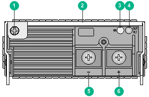
Figure 1 Front panel
|
(1) Captive screw |
(2) Handle |
|
(3) Power input LED |
(4) Power output LED |
|
(5) DC input negative terminal (–) |
|
|
(6) DC input positive terminal (+) |
|
LEDs
The power supply provides two status LEDs to indicate its operating status.
Table 1 LED description
|
LED |
Mark |
Status |
Description |
|
Power input LED |
IN |
Off |
No power input. |
|
The power supply has entered self-protection state because of input undervoltage. |
|||
|
Green |
Normal power input. |
||
|
Power output LED |
OUT/FLT |
Green |
Normal power output. |
|
Red |
The power supply has entered self-protection state because of one of the following conditions: · Output short-circuit · Output overcurrent · Output overvoltage · Input undervoltage · Overtemperature · Remote shutdown |
||
|
Orange |
High temperature alarm. |
|
|
NOTE: · The power output LED on a power supply is red when it has no power input or its connected circuit breaker is off but another power supply provides power to the device. · After the circuit breaker of the power supply is switched off, the LEDs on the power supply will remain on for a while. |
Technical specifications
Table 2 Technical specifications
|
Item |
Specification |
|
Rated input voltage range |
–48 to –60 VDC |
|
Rated output voltage |
12 VDC |
|
Maximum input current |
60 A |
|
Maximum output current |
200 A @ 12 VDC |
|
Maximum output power |
2400 W |
|
Dimensions (H × W × D) |
41 × 102 × 391 mm (1.61 × 4.02 × 15.39 in) |
|
Operating temperature |
–10°C to +50°C (+14°F to +122°F) |
|
Storage temperature |
–40°C to +70°C (–40°F to +158°F) |
|
Operating humidity |
30% to 95%, noncondensing |
|
Storage humidity |
10% to 95%, noncondensing |
Power supply configuration guidelines
Determine the number of power supplies based on the system power consumption and the power supply configuration based on the power input mode.
· In an environment with two mains power inputs, configure N+N power supply redundancy.
· In an environment with only one mains power input, configure N+1 or N+N power supply redundancy.
· Provide a circuit breaker for power input of each power supply. Make sure each circuit breaker has a current rating not less than 80 A.
|
|
NOTE: The value of N depends on the number of power supply slots in the device. N+1 or N+N must not be greater than the total number of power supply slots. |
Installing and removing the power supply
Installing the power supply
To avoid possible damage, strictly follow the procedure in Figure 2 to install the power supply.
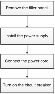
Figure 2 Power supply installation procedure
Before the installation, prepare an ESD wrist strap and a Phillips screwdriver yourself.
Installing the power supply
|
|
CAUTION: Before inserting a removed power supply into a power supply slot, make sure both LEDs on the power supply are off. |
To install the power supply:
1. Wear an ESD wrist strap, and make sure the strap makes good skin contact and is reliably grounded.
2. Remove the filler panel, if any, from the power supply slot. Use the Phillips screwdriver to loosen the captive screws on the filler panel, and then remove the filler panel out of the target slot.
The device requires a minimum of one power supply to supply power so it comes with one slot that does not have a filler panel installed. If you install the power supply in this slot, skip this step.
3. Unpack the power supply. Make sure the power supply model is as required.
4. Use the Phillips screwdriver to loosen the captive screw on the power supply handle and then pull the handle outward.
5. Correctly orient the power supply. Holding the power supply handle with one hand and supporting its bottom with the other, push the power supply slowly into the slot along the guide rails.
A power supply slot can be vertical or horizontal. The power supply installation method is similar for vertical and horizontal power supply slots. This procedure installs the power supply in a vertical slot.
Figure 3 Install the power supply into a vertical slot
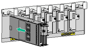
6. Press the handle back into the notch of the power supply.
7. Use the Phillips screwdriver to fasten the captive screw on the handle to secure the power supply to the chassis.
Connecting the power cord
|
|
WARNING! · Make sure each power cord has a separate circuit breaker. · Turn off the circuit breaker before connecting the power cord. · Use the power cord or ring terminals provided by H3C to meet the current requirements and match the power supply terminals. |
|
|
CAUTION: A DC power cord includes a negative wire and a positive wire. When connecting the power cord to the power source, make sure the circuit breaker switches for the positive wire and the negative wire are both turned off. |
To connect the power cord:
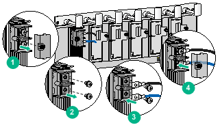
1. Use the Phillips screwdriver to loosen the screw on the terminal protection cover and then remove the protection cover from the power supply.
2. Use the Phillips screwdriver to loosen the screws on the wiring terminals.
3. Connect one end of the blue power wire marked with – to the negative terminal (–) on the power supply and fasten the screw.
4. Connect one end of the black power wire marked with + to the positive terminal (+) on the power supply and fasten the screw.
5. Put the protection cover on the wiring terminals and fasten the screw.
Figure 4 Connecting the power cord to the power supply
6. Connect the other end of the blue and black power wires to the negative terminal (–) and positive terminal (+) on the power source, respectively.
Removing the power supply
To avoid possible damage, strictly follow the procedure in Figure 5 to remove the power supply.
Figure 5 Power supply removal procedure
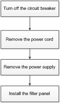
Before removing a power supply, prepare an ESD wrist strap and a Phillips screwdriver yourself.
Removing the power cord
1. Turn off the circuit breaker switches for the power supply.
After the circuit breaker switches for the power supply are turned off, the LEDs on the power supply will remain on for a while.
2. Wear an ESD wrist strap, and make sure the strap makes good skin contact and is reliably grounded.
3. Remove the power cord from the power supply.
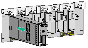
Removing the power supply
1. Use the Phillips screwdriver to loosen the captive screw on the power supply handle.
2. Hold the captive screw on the handle and then pull the handle outward.
Figure 6 Removing the power supply
4. Put the removed power supply on an antistatic mat.
5. Install the filler panel back in the power supply slot, and fasten the captive screws on the filler panel.
