- Table of Contents
- Related Documents
-
| Title | Size | Download |
|---|---|---|
| 01-Text | 26.55 MB |
Contents
Examining the installation site
Installation tools and equipment
Installing cage nuts for attaching mounting brackets
3 Installing removable components
Installing cable management brackets
(Optional.) Replace environment management modules
Installing a filler panel in a fabric module slot
Removing a filler panel from a fabric module slot
Removing the filler panel from a fan tray slot
Installing power supplies and power trays
Power trays and power supplies
(Optional) Installing power trays
Installing the air filter in the top hood
Installing transceiver modules
Installing a transceiver module
Viewing device startup information
1 Preparing for installation
ESD prevention
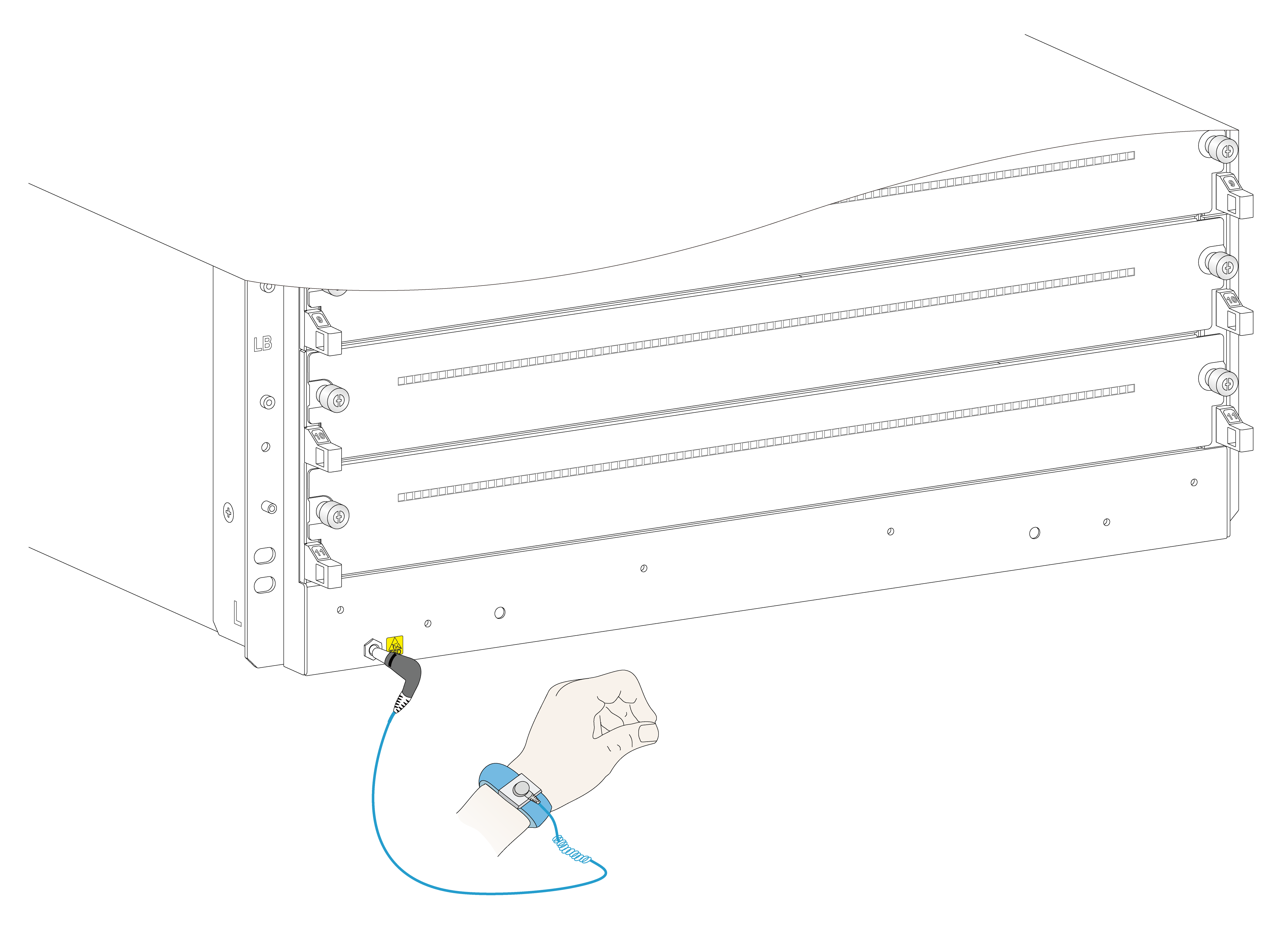
To prevent electronic components from electrostatic discharge (ESD) damage, wear an ESD wrist strap before working with the device or any module. Make sure the wrist strap makes good skin contact and is reliably grounded.
Figure 1-1 Attaching an ESD wrist strap
|
ESD socket (with an ESD sign) |
Examining the installation site
The device must be used indoors. To make sure the device operates correctly and to prolong its service lifetime, the installation site must meet the load-bearing, temperature, humidity, cleanness, EMI, grounding, power supply, ventilation, and space requirements. As a best practice, reserve a minimum of 1.2 m (3.94 ft) of clearance between the device and walls or other devices. For more information, see H3C S12500CR Switch Router Series Installation Guide.
Installation tools and equipment
No installation tools and equipment are provided with the device. Prepare them yourself as required.
2 Installing the device
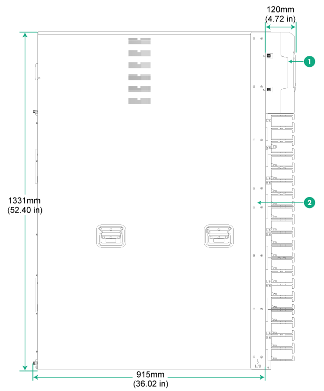
Device dimensions
Figure 2-1 Device dimensions
|
(1) Top hood |
(2) Mounting bracket |
Rack requirements
Table 2-1 Rack requirements
|
Device dimensions |
Rack requirements |
|
· Height—1331 mm (52.40 in) (30 RU). · Width—442 mm (17.40 in). · Chassis depth—920 mm (36.22 in) · Total depth—1035 mm (40.75 in) ¡ 120 mm (4.72 in) from the rack-mounting surface of the mounting bracket to the top hood front end. ¡ 915 mm (36.02 in) from the rack-mounting surface of the mounting bracket to the captive screw on the fan tray at the chassis rear. |
· A minimum of 1.1 m (3.61 ft) in depth (recommended.) · A minimum of 130 mm (5.12 in) from the front rack post to the front door. · A minimum of 950 mm (37.40 in) from the front rack post to the rear door. |
|
|
NOTE: As a best practice, use a rack that has a single door at the front. |
Slide rail requirements
|
|
CAUTION: The device is heavy. Install the device at the lowest possible position. |
Follow these guidelines for attaching the LSXM1BSR slide rails to the rack:
· The LSXM1BSR slide rails include a left slide rail, a right slide rail, and a front plate. Make sure all components are correctly installed.
· Before attaching the slide rails, read signs on the slide rails to identify the right and left slide rails and their front and rear ends. Mount the front end of the slide rails to the front rack posts.
· Make sure the load-bearing plane of the slide rails is perpendicular to the rack posts.
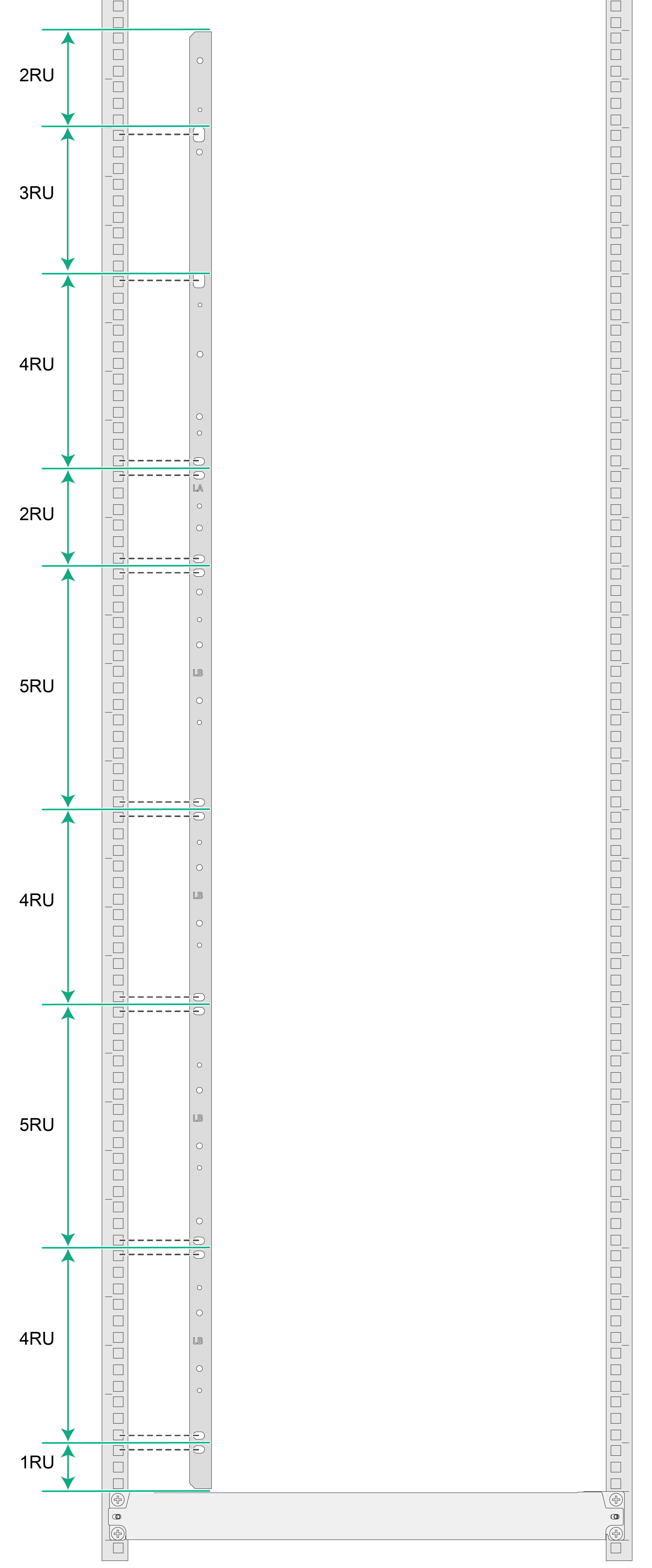
Installing cage nuts for attaching mounting brackets
1. As shown in Figure 2-2, determine the cage nut installation holes and then mark them on the front rack post.
2. Insert cage nuts into the marked square holes in the front rack posts.
3. Install cage nuts in the marked square holes on the front rack posts.
Figure 2-2 Installing cage nuts
Mounting the device in a rack
|
|
WARNING! To avoid device damage or bodily injury, follow these guidelines to lift and move the device: · Use the chassis handles, rather than the handles of the components (fan trays, power supplies, and modules) as well as the chassis air vents, to move the chassis. · The device is heavy. As a best practice, use a forklift to lift and move the device. |
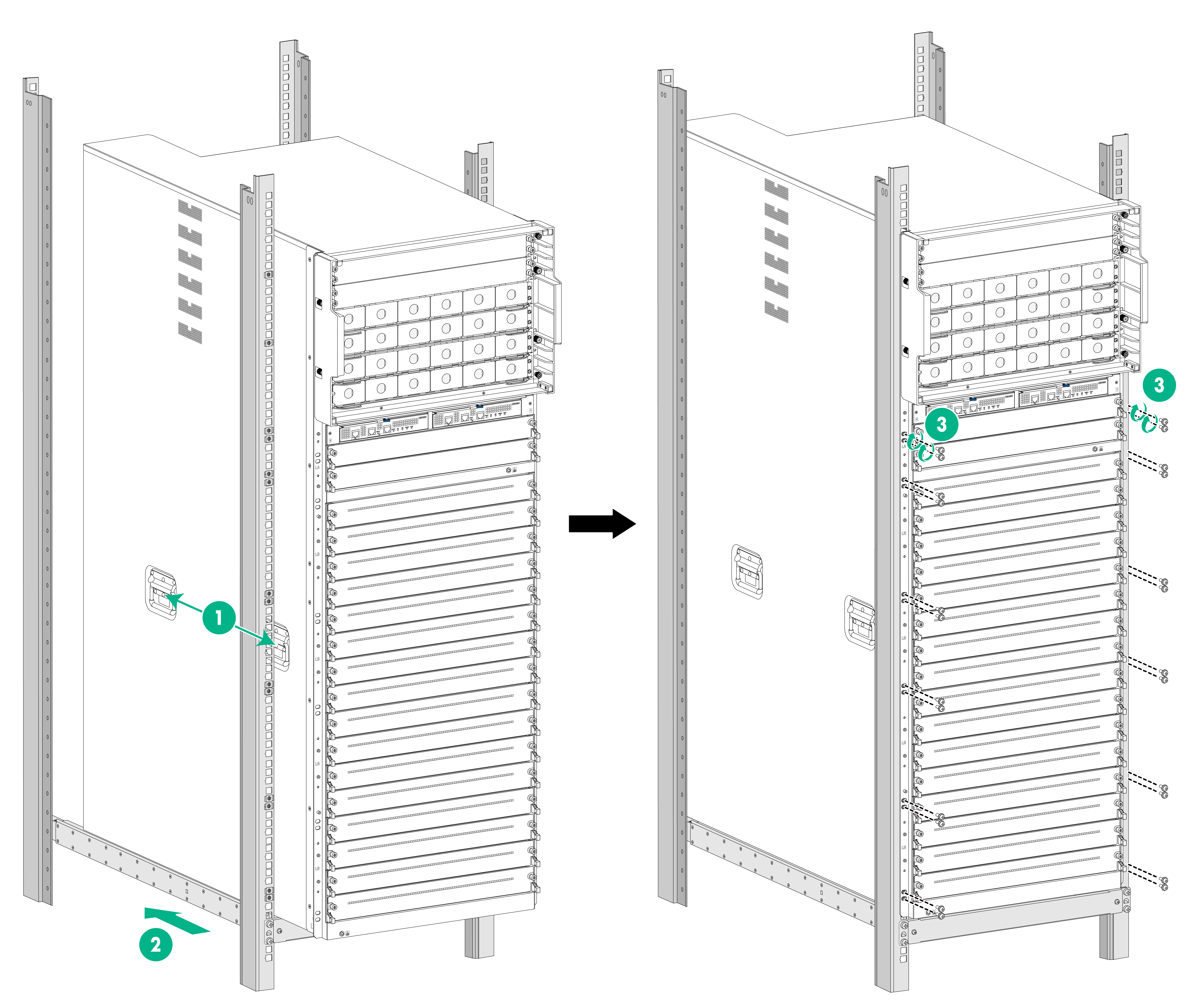
To mount the device in the rack:
1. Face the rear of the chassis towards the front of the rack.
2. Lift the device to a height slightly above the slide rails by holding the chassis handles.
3. Place the device on the slide rails from the front of the rack and slide the device along the guide rails until the mounting brackets on the device touch the front rack posts tightly, as shown by callout 2 in Figure 2-3.
|
|
WARNING! After you place the device on the slide rails installed on the rack, do not leave go of your hands immediately because this might tip the device, damaging the device or even causing bodily injury. |
4. Use M6 screws provided with the device to secure the mounting brackets to the rack posts.
As a best practice, use a torque of 30 kgf-cm (2.94 Nm) to fasten the M6 screws.
If the mounting holes in the mounting brackets cannot align with the cage nuts on the rack, verify the following items:
¡ The bottom edge of the slide rail aligns with the middle of the narrower metal area between holes.
¡ The cage nuts are installed in the correct holes.
Figure 2-3 Mounting the device in the rack
|
(1) Chassis handle |
(2) Slide the chassis into the rack |
|
(3) Use screws to secure the mounting brackets to the rack |
|
Grounding the device
|
|
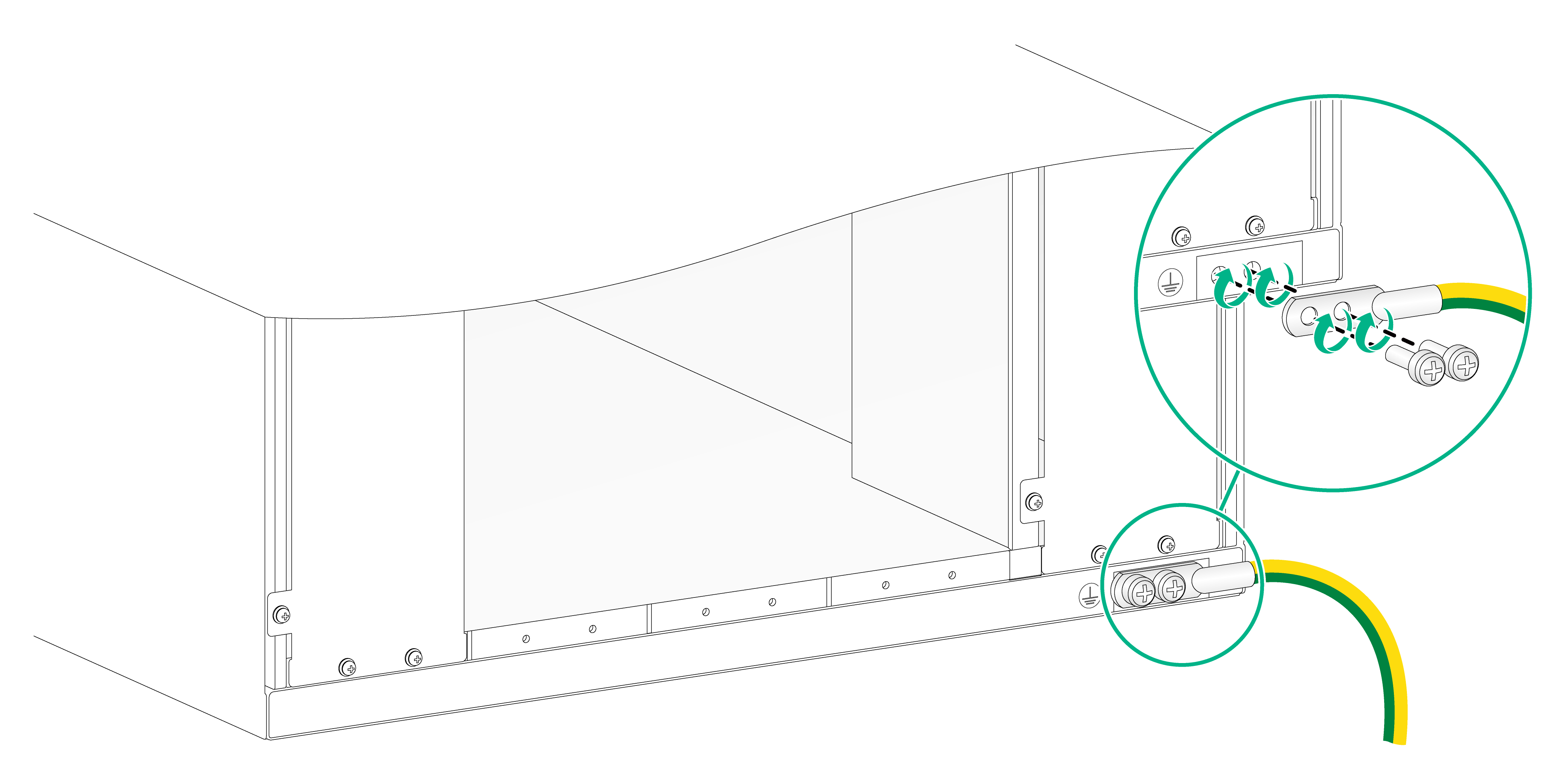
CAUTION: · Reliably grounding the device is crucial to lightning protection and EMI protection. Ground the device reliably before you use it. · To guarantee the grounding effect, use the grounding cable (yellow-green grounding cable) provided with the device. · Connect the grounding cable to the grounding strip in the equipment room or the grounding point on the rack. Do not connect it to a fire main or lightning rod. |
|
|
IMPORTANT: The grounding cable provided with the device is NEBS compliant. Connect the two-hole grounding lug of the grounding cable to the chassis and the ring terminal to a grounding strip. |
To ground the device:
1. Unpack the grounding cable.
2. Use a screwdriver to remove the grounding screws (M6 screws) from the grounding point at the rear of the chassis.
A grounding sign is provided with the grounding points.
3. Use the M6 screws to attach the two-hole grounding lug of the grounding cable to grounding point on the chassis.
As a best practice, use a torque of 30 kgf-cm (2.94 Nm) to fasten the M6 screws.
4. Connect the ring terminal of the grounding cable to the grounding point on the rack or to the grounding strip.
Figure 2-4 Grounding the device
3 Installing removable components
This section describes the installation procedures for the supervisor engine units (SEUs, also called MPUs), environment management modules, interface modules, fabric modules, fan trays, power trays, and power supplies. For the compatibility matrix between these modules and the device models, see H3C S12500CR Switch Router Series Hardware Reference.
|
|
WARNING! Long-time exposure to strong air flow might cause discomfort. As a best practice, do not stand close to the air outlet vents while the device is operating. If you must be next to the device on the air outlet vent side for an extended period, avoid the air flow or take other protective measures. |
|
|
CAUTION: To ensure adequate ventilation of the device, install filler panels in the unused module slots and power supply slots. |
Attaching an ESD wrist strap
To prevent electronic components from ESD damage, wear an ESD wrist strap when installing removable components. Make sure the wrist strap makes good skin contact and is reliably grounded.
Installing cable management brackets
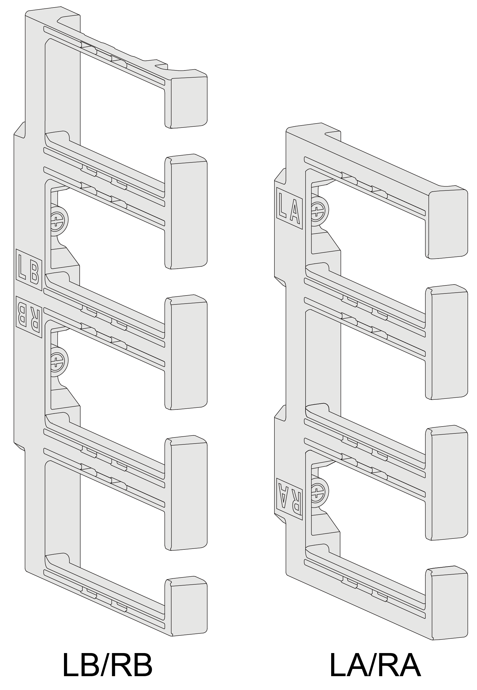
The device comes with two LA/RA and eight LB/RB cable management brackets. The cable management brackets are installed at the two sides of the chassis front panel with LA/RA cable management brackets at the upper part and LB/RB cable management brackets at the middle and lower parts.
Figure 3-1 Cable management brackets
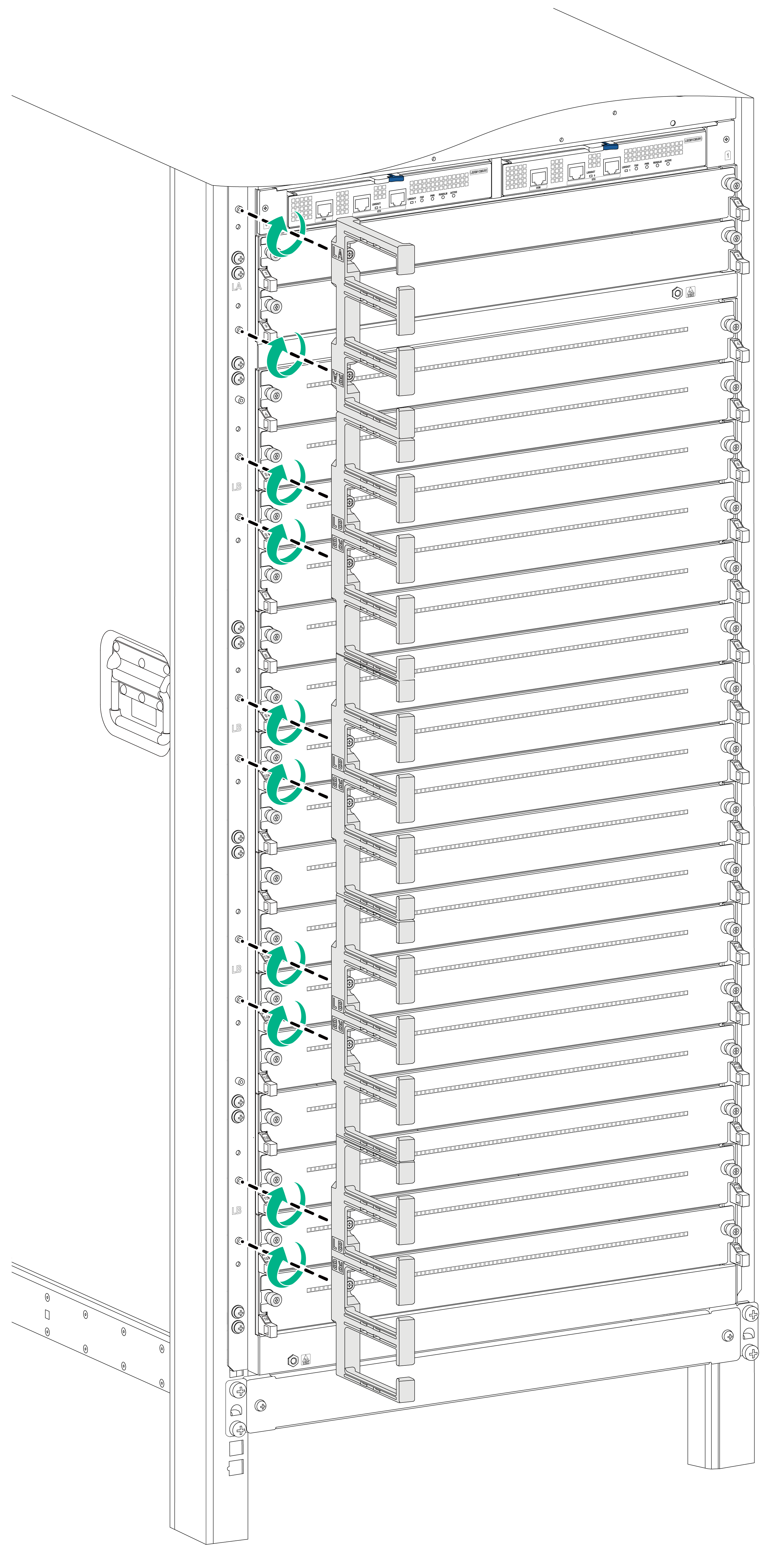
The cable management brackets use the same procedure for installation at the left side and right side of the front panel. The following procedure installs a cable management bracket at the left side.
To install a cable management bracket:
1. Identify the installation position for the cable management bracket on the mounting bracket. The LA, LB, RA, and RB marks on the mounting brackets indicate the types of cable management brackets to be installed.
2. Orient the cable management bracket, with the lettering facing upward, and then position the cable management bracket near its installation position on the mounting bracket.
3. Align the captive screws on the cable management bracket with the holes in the mounting bracket.
4. Fasten the captive screws to secure the cable management bracket to the mounting bracket.
As a best practice, use a torque of 5 kgf-cm (0.49 Nm) to fasten the captive screws.
Figure 3-2 Installing a cable management bracket
Installing SEUs
|
|
CAUTION: · If you are not to install an SEU in an SEU slot, keep the filler panel in the slot. · When you install an SEU, avoid damaging the connectors on the SEU. · When you install or remove the filler panel while the device is operating, hold both sides of the filler panel with two hands. The filler panel might be drawn into the chassis when the fan speed is high. |
You can install one SEU, or two SEUs for redundancy on the device. If you are to install one SEU, install it in either of the SEU slots. The ejector levers of the SEUs and the ejector lever pillow blocks on the SEU slots have pink marks.
To install an SEU:
1. As shown by callout 1 in Figure 3-3, remove the filler panel from the target SEU slot.
Keep the removed filler panel secure for future use.
2. As shown by callout 2 in Figure 3-3, hold both sides of the SEU with two hands, and insert the SEU into the slot along the guide rails slowly and steadily.
3. As shown by callout 3 in Figure 3-3, open the ejector levers of the SEU when most part of the SEU is inserted in the slot.
4. Push the SEU until the brakes on its ejector levers touch the slot edges tightly.
5. As shown by callout 4 in Figure 3-3, continue to push the SEU by its middle part on the front panel until you cannot move it.
6. As shown by callout 5 in Figure 3-3, close the ejector levers until they come in close contact with the front panel.
7. As shown by callout 6 in Figure 3-3, fasten the captive screws on the SEU.
As a best practice, use a torque of 5 kgf-cm (0.49 Nm) to fasten the captive screws.
(Optional.) Replace environment management modules
|
|
CAUTION: · Before replace an environment management module, remove cables from the module. · Do not use excessive force during the replacement procedure. |
The device comes with two environment management modules installed.
To replace an environment management module:
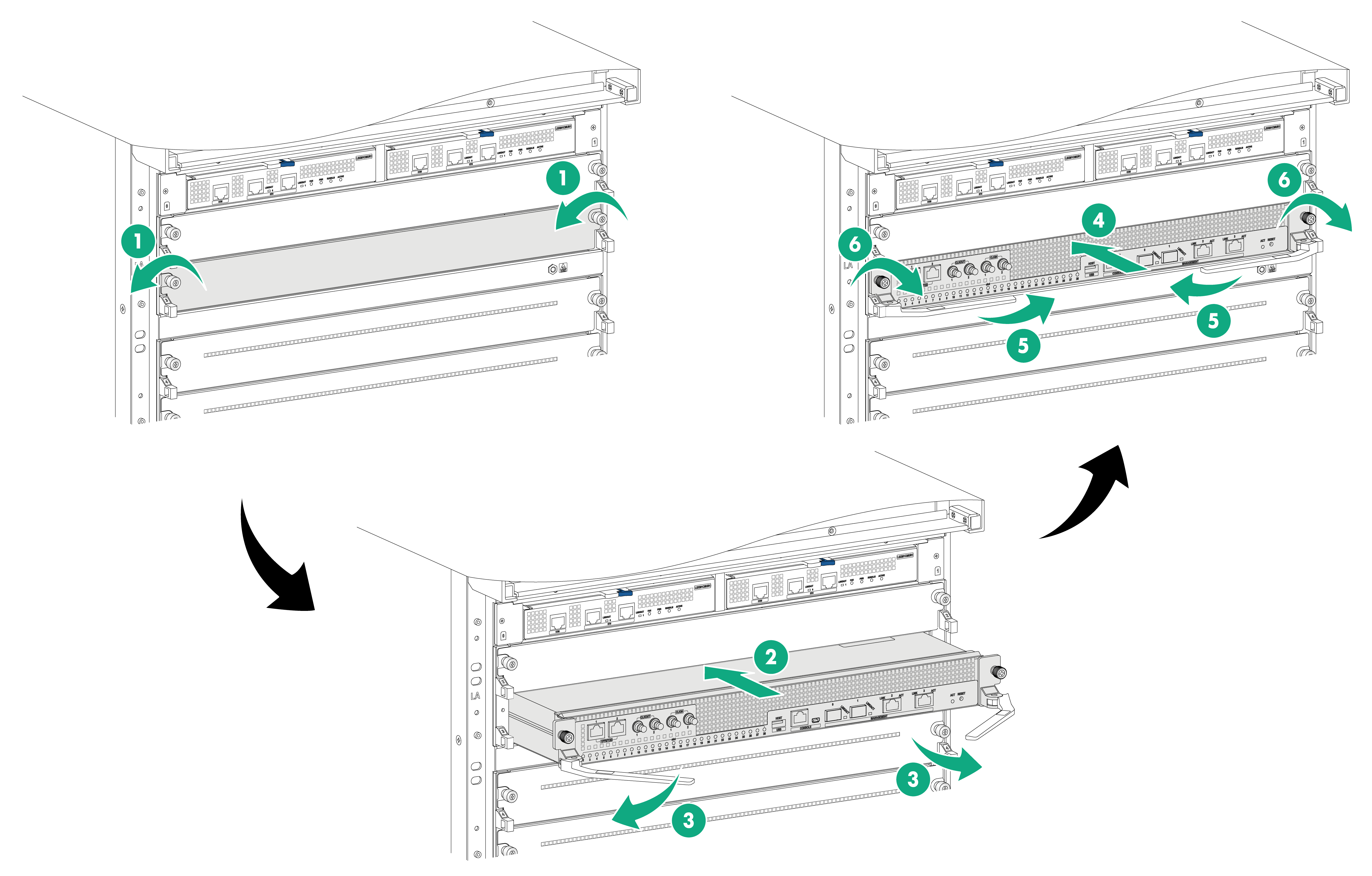
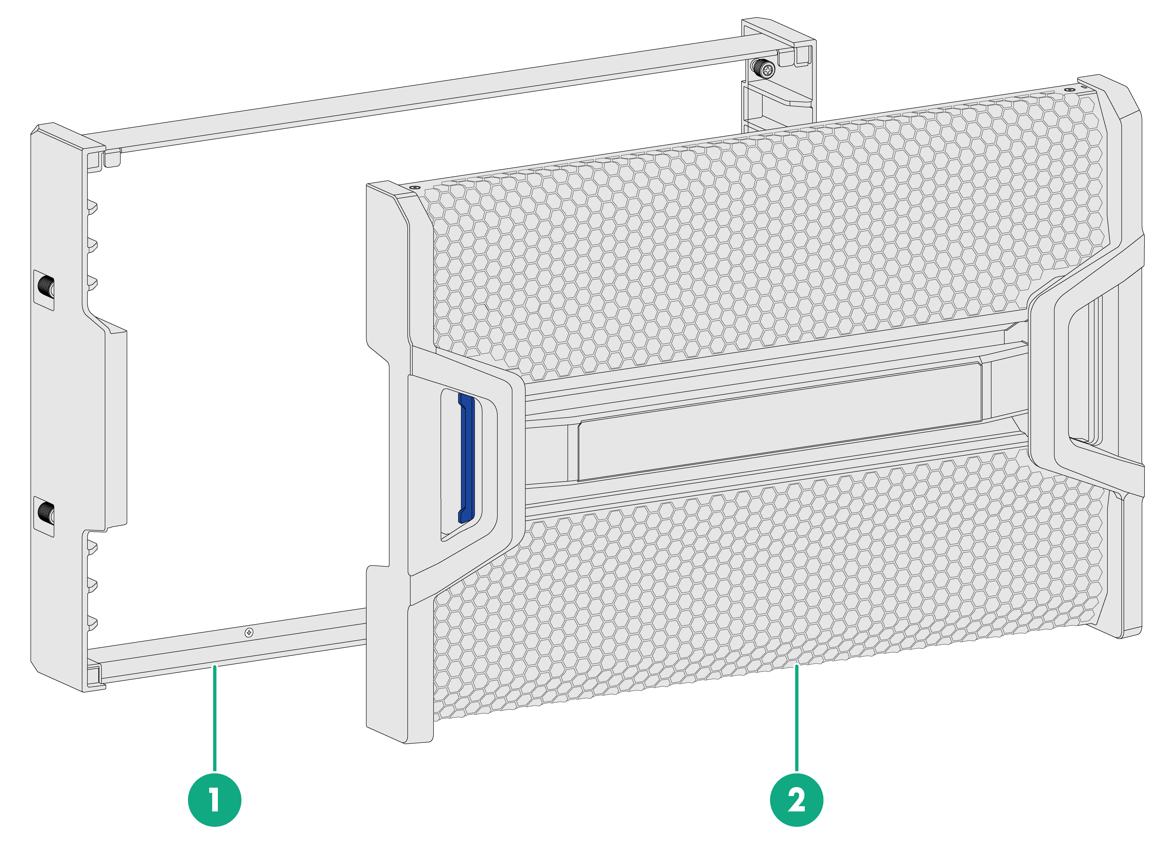
1. As shown in Figure 3-4, press the latch rightwards to release the ejector lever. Slowly pull the environment management module out of the slot.
2. Unpack a new environment management module.
3. Press the latch on the new module rightwards to release the ejector lever and then fully open the ejector lever.
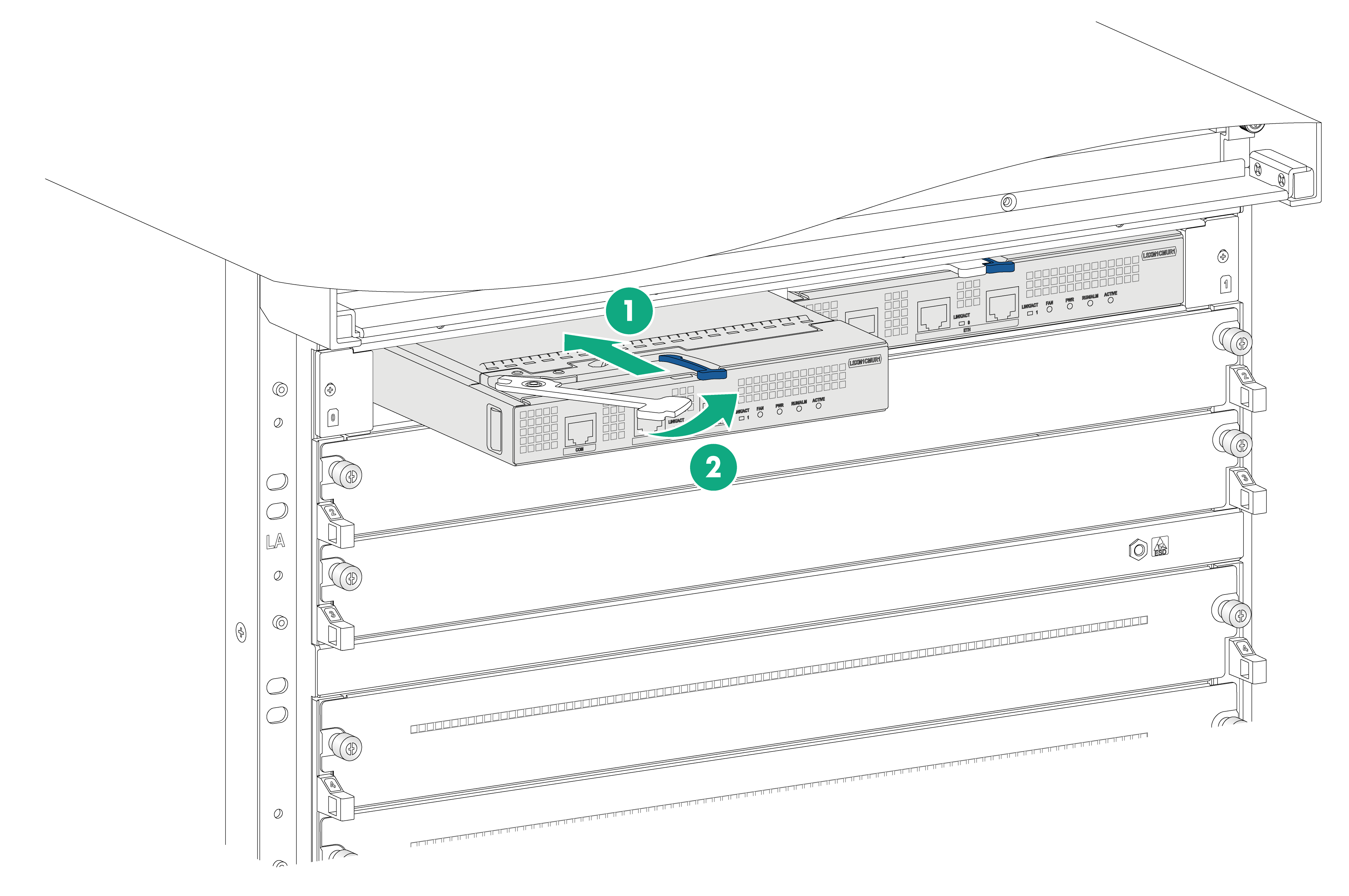
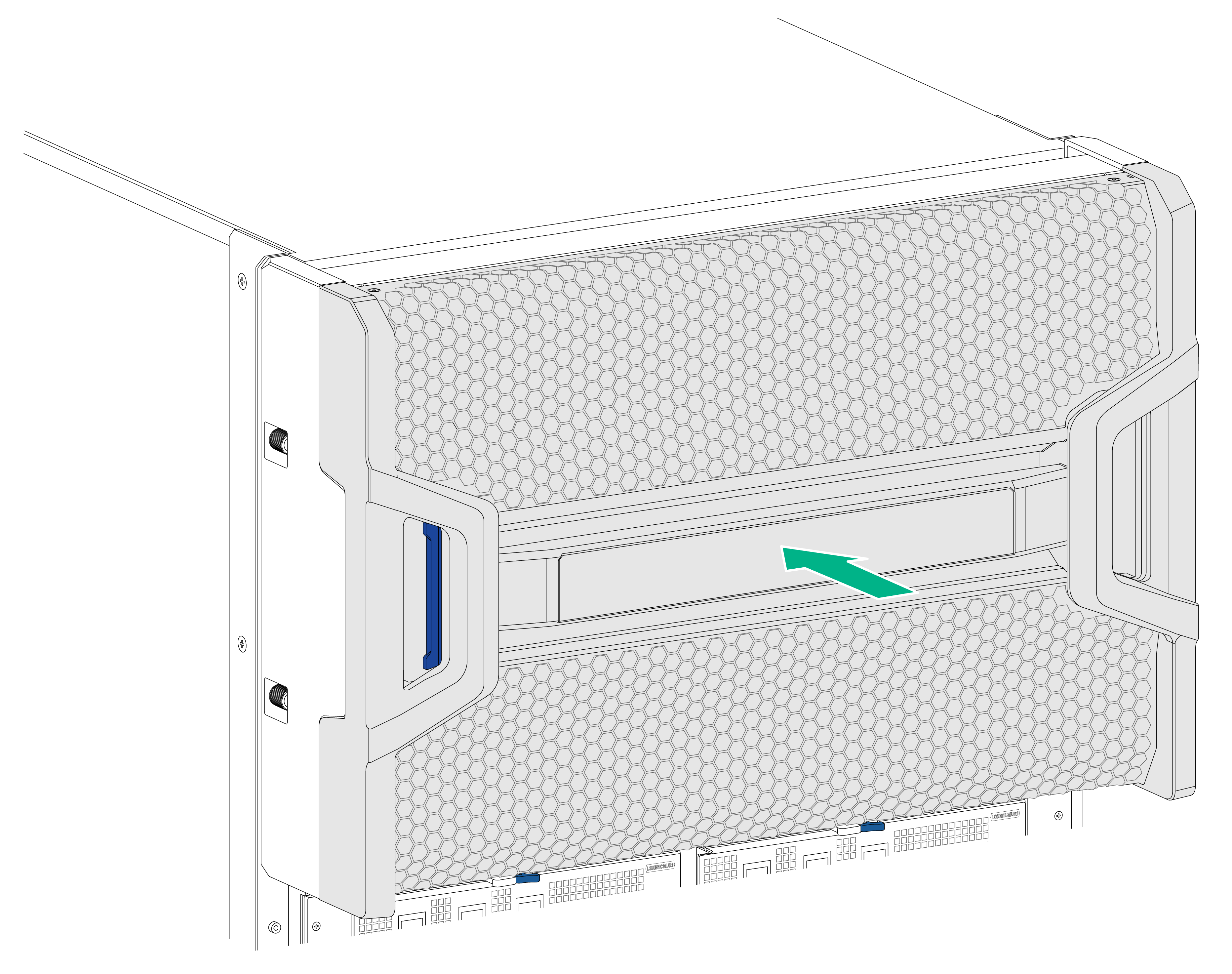
4. Correctly orient the environment management module, and push it slowly into the slot along the guide rails until the brake on the ejector lever touch the slot edges tightly. See callout 1 in Figure 3-5.
5. As shown by callout 2 in Figure 3-5, push the ejector lever inward until the latch locks the ejector lever.
Figure 3-4 Removing an environment management module
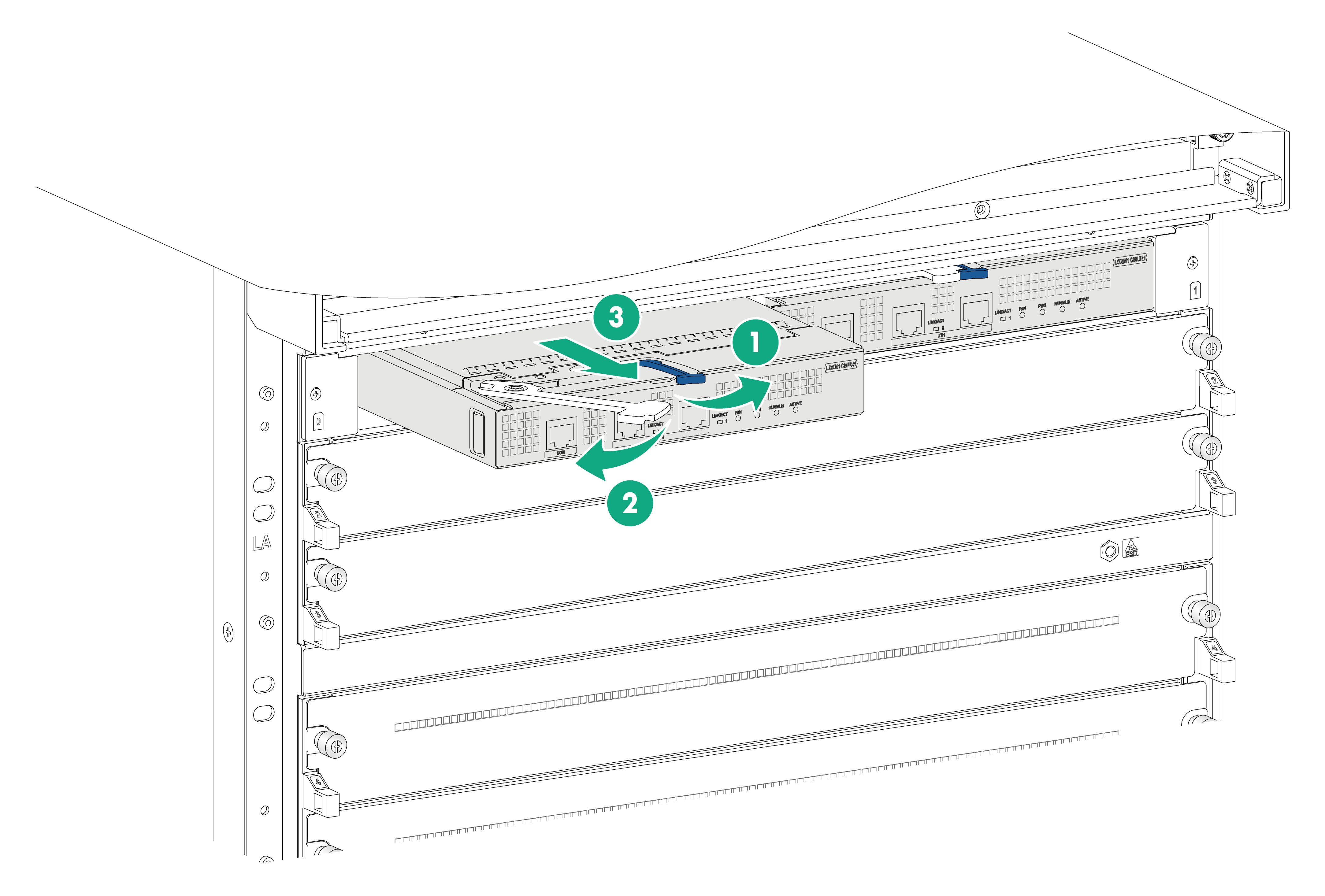
Figure 3-5 Installing an environment management module
Installing interface modules
|
|
CAUTION: When you install or remove the filler panel while the device is operating, hold both sides of the filler panel with two hands. The filler panel might be drawn into the chassis when the fan speed is high. |
The S12500R interface modules with the dimensions 50 × 432.6 × 519.8 mm (1.97 × 17.03 × 20.46 in) are available for the device. To install an S12500R interface module on the device, first install an interface module adapter in the target interface module slot. For more information about installing an interface module adapter, see H3C S12500CR LSXM1IMAA Interface Module Adapter User Manual.
For an interface module slot installed with an interface module adapter, remove the adapter from the slot if you are not to install an interface module in the slot to ensure adequate heat dissipation.
The ejector levers of the interface modules and the ejector lever pillow blocks on the interface module slots have purple marks.
To install an interface module:
1. As shown by callout 1 in Figure 3-6, remove the filler panel from the target interface module slot.
Keep the removed filler panel secure for future use.
2. As shown by callout 2 in Figure 3-6, hold both sides of the interface module with two hands, and insert the interface module into the slot along the guide rails slowly and steadily.
3. As shown by callout 3 in Figure 3-6, open the ejector levers of the interface module when most part of the interface module is inserted in the slot.
4. Push the interface module until the brakes on its ejector levers touch the slot edges tightly.
5. As shown by callout 4 in Figure 3-6, continue to push the interface module by its middle part on the front panel until you cannot move it.
6. As shown by callout 5 in Figure 3-6, close the ejector levers until they come in close contact with the front panel.
7. As shown by callout 6 in Figure 3-6, fasten the captive screws on the interface module.
As a best practice, use a torque of 5 kgf-cm (0.49 Nm) to fasten the captive screws.
Figure 3-6 Installing an interface module
Installing fabric modules
The device comes with all fabric module slots empty. Purchase fabric modules and filler panels for the device as required.
Installing fabric modules
Follow these restrictions and guidelines when you install fabric modules:
· When you install a fabric module, avoid damaging the connectors on it.
· Fan trays cover fabric module slots as follows. Before installing a fan tray, install fabric modules or filler panels in the fabric module slots that the fan tray will cover.
¡ FAN1—Fabric module slots 20 and 21.
¡ FAN2—Fabric module slots 22 and 23.
¡ FAN3—Fabric module slots 24 and 25.
¡ FAN4—Fabric module slots 26 and 27.
¡ FAN5—Fabric module slot 28.
· Slots 20, 21, and 28 can be empty without a fabric module or filler panel installed. If you are not to install a fabric module in slot 22, 23, 24, 25, 26, or 27, install a filler panel.
· To use S12500R interface modules on the device, install fabric modules in slots 22 to 27. The S12500R interface modules cannot start up if no fabric modules are installed in the six slots.
· If you want to install or replace fabric modules under two fan trays when the device is operating, perform the following steps:
a. Remove a fan tray and install or replace the fabric modules.
b. Reinstall the fan tray.
c. After the fan tray operates correctly, remove another fan tray and install or replace the fabric modules.
· Before installing a fabric module, make sure it is compatible with the interface modules installed on the device. For example, type K fabric modules can be used only with Type K interface modules. Type K interface modules have a K in their module identifiers (for example, LSXM1CDQ36KBR1) and Type K fabric modules have a character string of SFK in their module identifiers (for example, LSXM1SFK08GR1).
To install a fabric module:
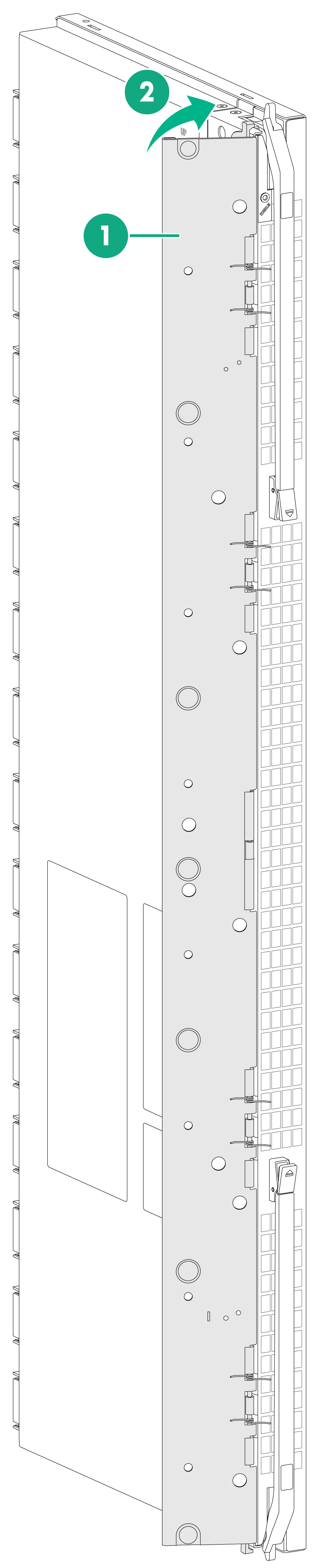
1. As shown in Figure 3-7, if the fabric module comes with an air deflector, make sure the air deflector is closed before the installation.
After you remove a fabric module with an air deflector, be sure to close the air deflector.
2. Remove the protection box from the connector side of the fabric module. For information about removing the protection box, see Figure 3-8.
3. Release the ejector levers by pressing the spring clips.
4. Orient the fabric module with the side marked "UP" facing up. Hold the fabric module front panel near the ejector levers with one hand and support the module bottom with the other. Place the module bottom on the bottom guide rails of the chassis. Align the fabric module with the target slot and insert it into the slot along the guide rails. See callout 1 in Figure 3-9.
Keep the module parallel to the slot to avoid touching other components in the chassis.
5. As shown by callout 2 in Figure 3-9, continue to push the fabric module until the brakes on its ejector levers touch the slot edges tightly. Simultaneously rotate the ejector levers inward until the spring clips lock the ejector levers in place and the fabric module is completely seated in the slot.
Figure 3-7 Fabric module with an air deflector
|
(1) Air deflector |
(2) Close the air deflector until it is locked in place. |
Figure 3-8 Removing the protection box
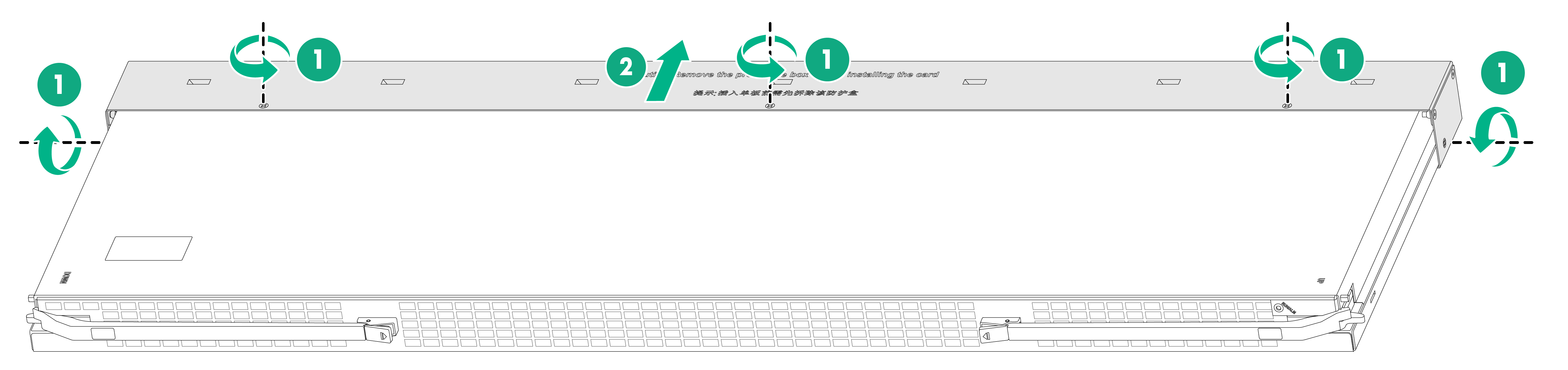
|
(1) Loosen the captive screws on the protection box |
|
(2) Hold the protection box to disengage it from the connector side of the fabric module |
Figure 3-9 Installing a fabric module
Installing a filler panel in a fabric module slot
1. Loosen the captive screws on the ejector levers and rotate outward the ejector levers.
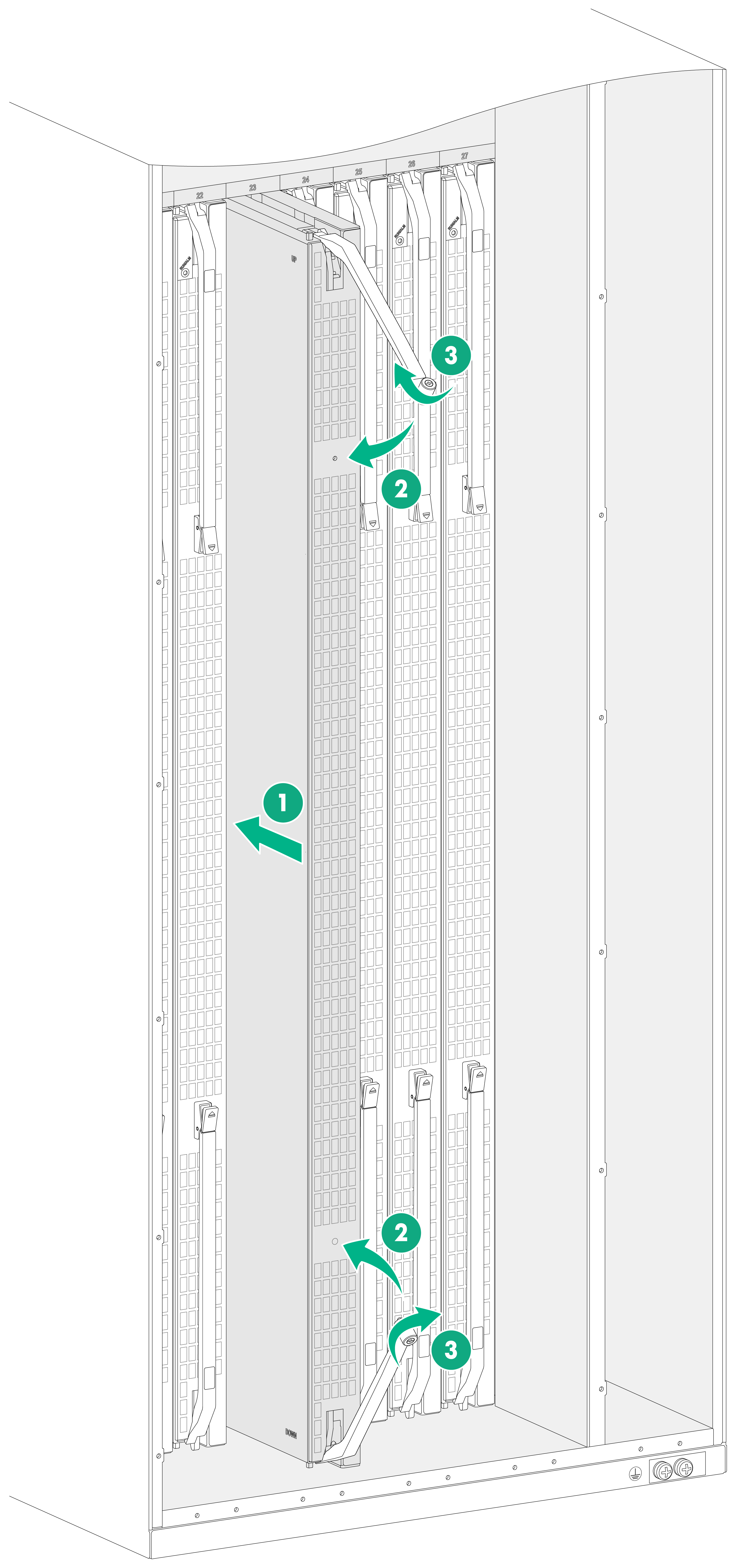
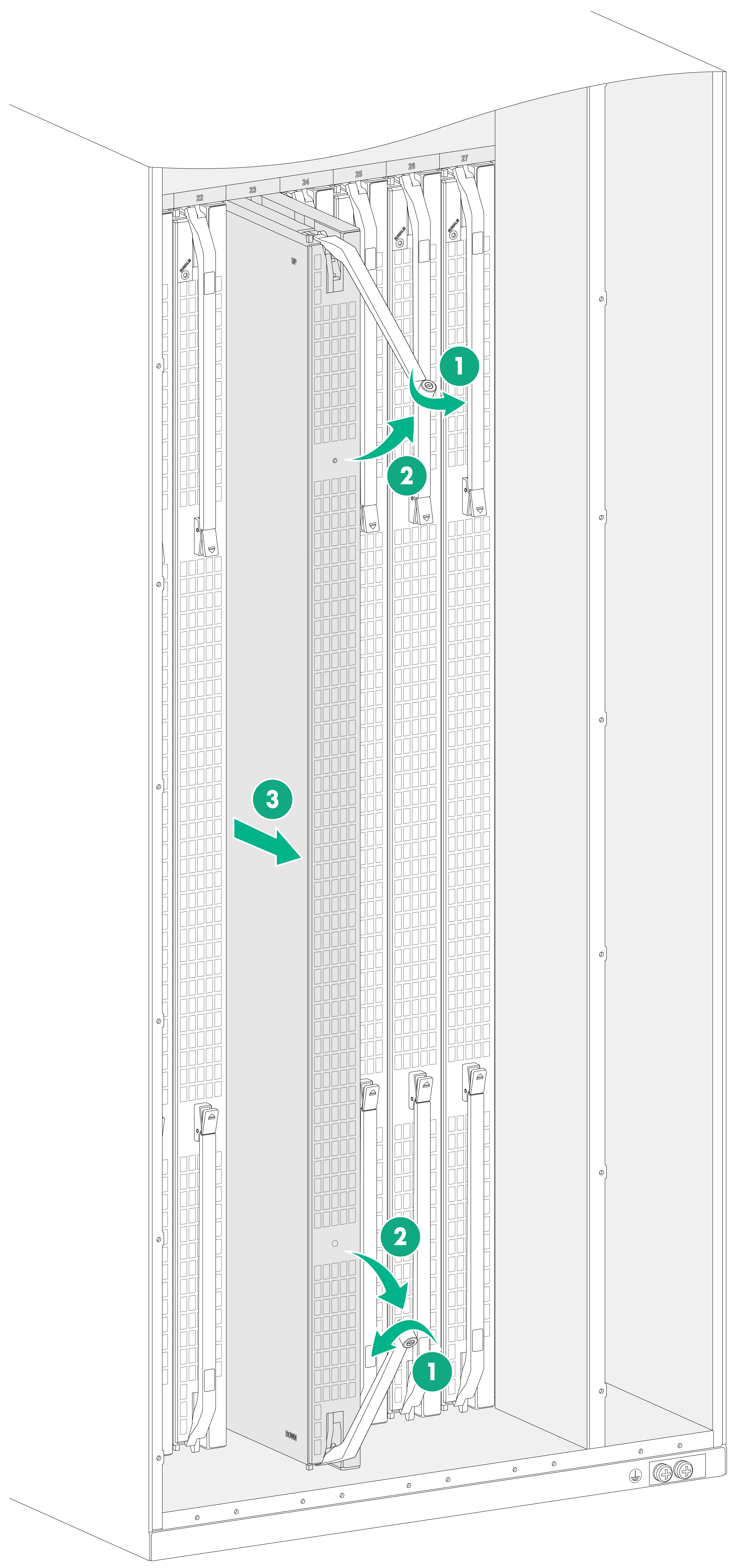
2. Orient the filler panel with the side marked "UP" facing up. Hold the filler panel front panel near the ejector levers with one hand and support its bottom with the other. Place the filler panel bottom gently on the bottom guide rails of the chassis. Align the filler panel with the fabric module slot. Push the filler panel slowly into the slot along the guide rails. See callout 1 in Figure 3-10.
Keep the filler panel parallel to the fabric module slot to avoid touching other components in the chassis.
3. As shown by callout 2 in Figure 3-10, continue to push the filler panel until the brakes on its ejector levers touch the slot edges tightly. Simultaneously rotate the ejector levers inward.
4. As shown by callout 3 in Figure 3-10, fasten the captive screws on the ejector levers.
As a best practice, use a torque of 5 kgf-cm (0.49 Nm) to fasten the captive screws.
Figure 3-10 Installing a filler panel in a fabric module slot
Removing a filler panel from a fabric module slot
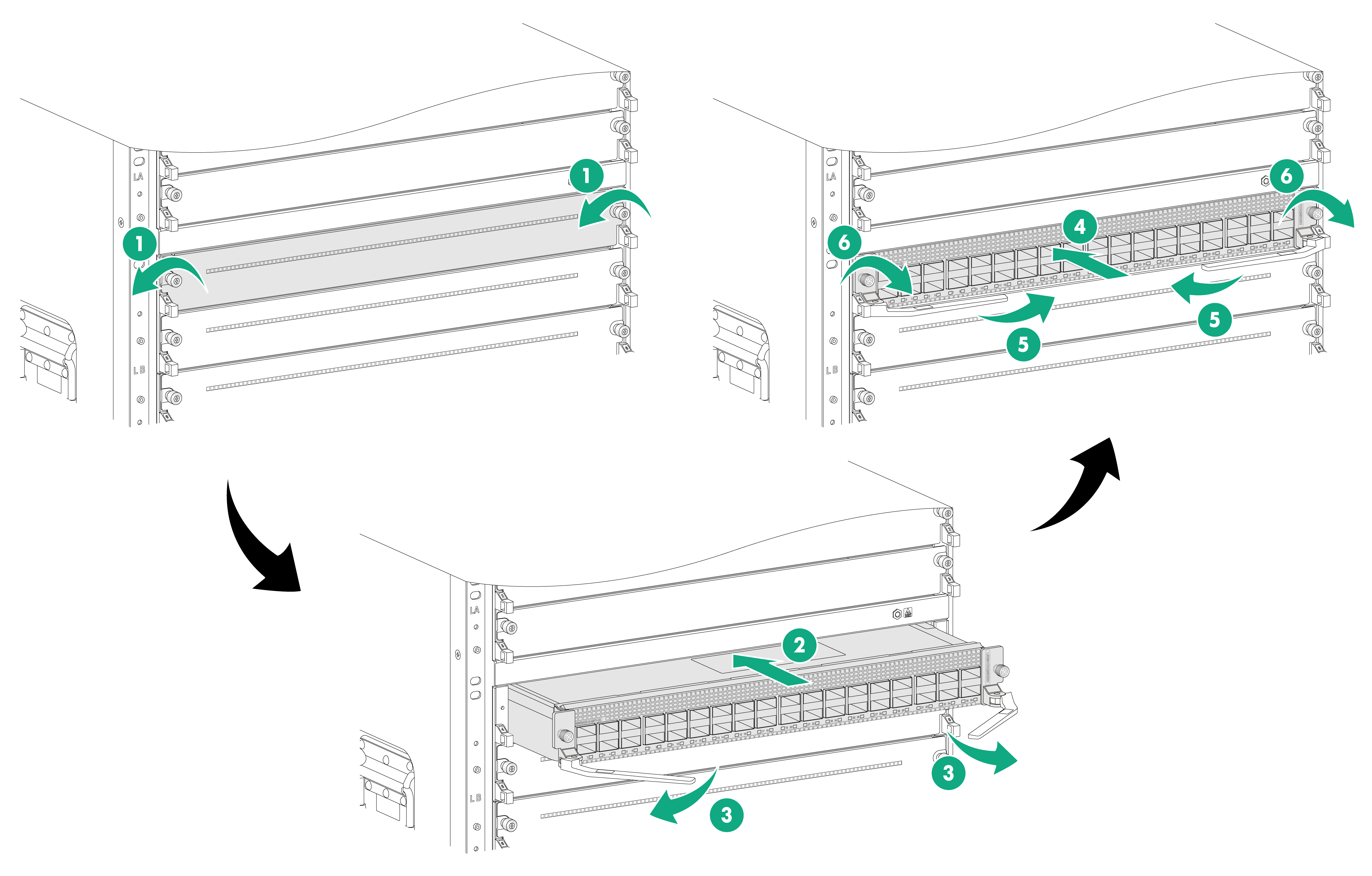
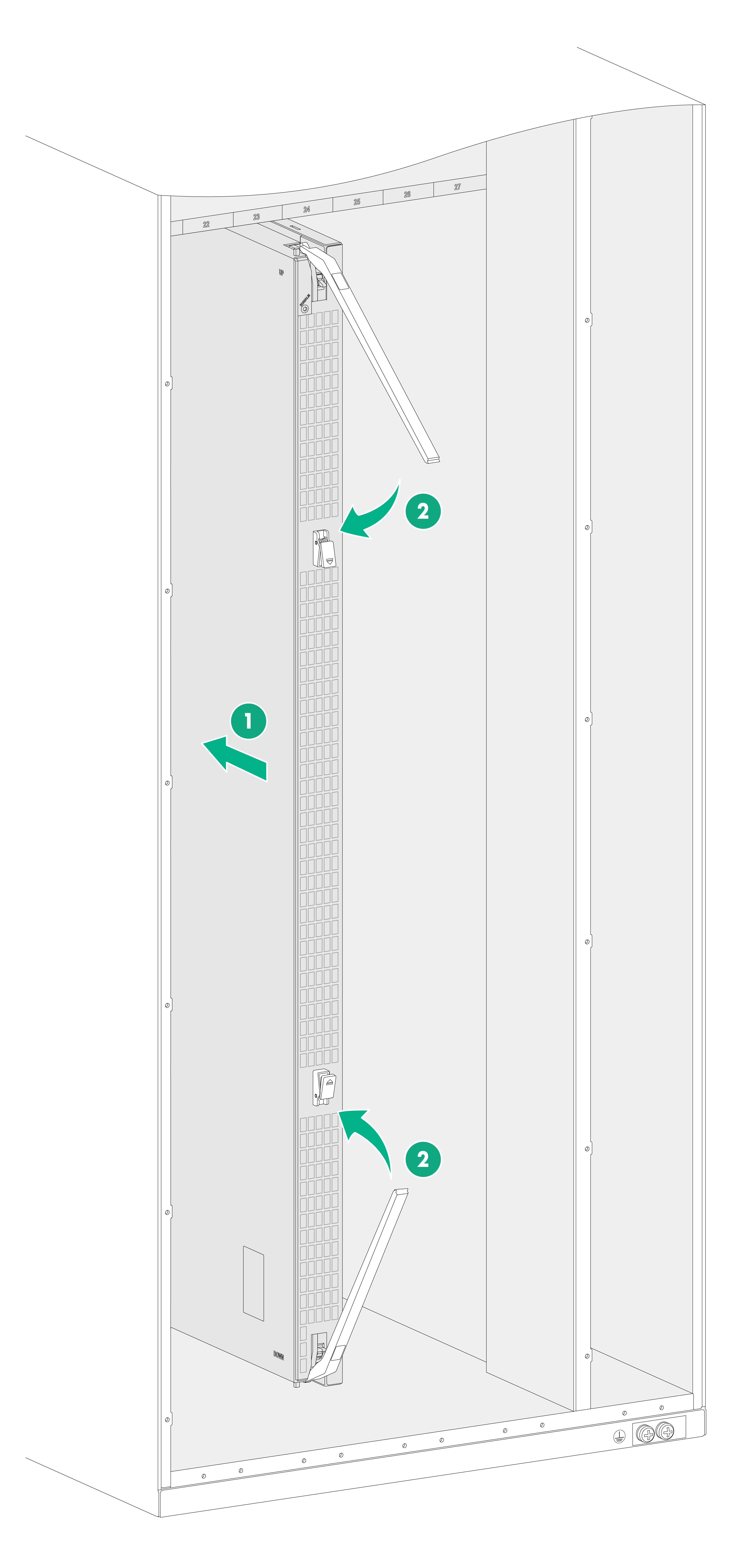
1. As shown by callout 1 in Figure 3-11, loosen the captive screws on the ejector levers.
2. As shown by callout 2 in Figure 3-11, rotate outward the ejector levers. Then pull the filler panel part way out of the slot.
3. As shown by callout 3 in Figure 3-11, hold the filler panel by the top and bottom edges to pull the filler panel out of the slot.
Keep the removed the filler panel secure for future use.
Figure 3-11 Removing the filler panel from a fabric module slot
Installing fan trays
Follow these restrictions and guidelines when you install a fan tray:
· Fan trays cover fabric module slots. Before installing a fan tray, install fabric modules or filler panels in the fabric module slots that the fan tray will cover.
· The device comes with the FAN1 and FAN5 slots installed with filler panels and the FAN2 to FAN4 slots empty. To ensure adequate heat dissipation, make sure all fan trays slots are installed with fan trays.
· Before installing a fan tray in the FAN1 or FAN5 slot, remove the filler panel from the slot.
· The fan tray is hot swappable. Follow these guidelines when you replace a fan tray:
¡ Ensure electricity safety.
¡ To prevent dust and ensure adequate heat dissipation, keep the old fan tray in the chassis until a new fan tray is ready to be installed. As a best practice, finish replacing a fan tray within 3 minutes.
¡ When you hot-swap a fan tray, the remaining fan tray automatically increases the rotation speed and makes louder noise. Take protection measures such as wearing an earmuff or earplug.
¡ Long-time exposure to strong air flow might cause discomfort. To avoid this hazard, do not stand close to the air outlet vents when the device is operating. If you must be next to the device on the air outlet vent side for an extended period, avoid the air flow or take protective measures.
Installing a fan tray
The following procedure installs a fan tray in the FAN2 slot.
To install a fan tray:
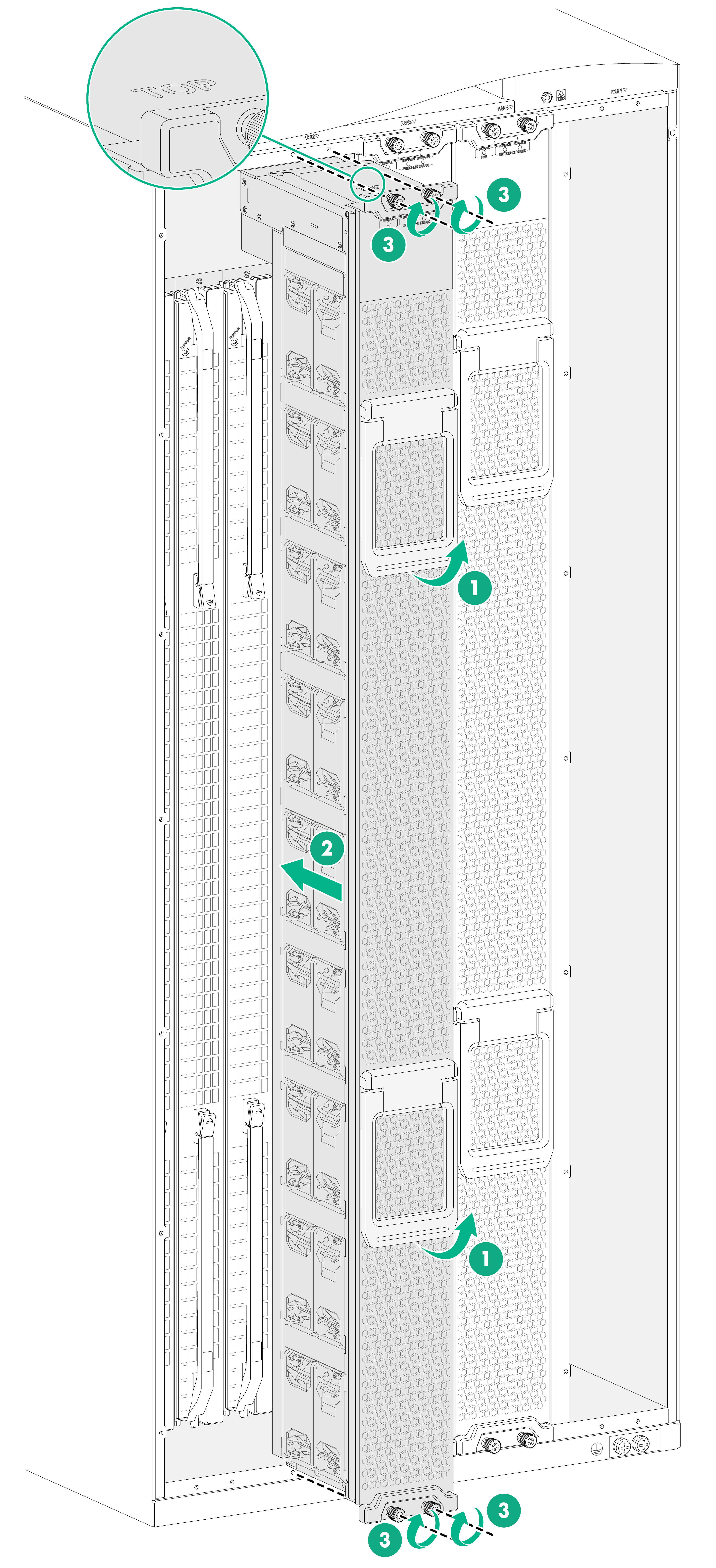
1. As shown by callout 1 in Figure 3-12, orient the fan tray with the side marked "TOP" facing up and pivot up the fan tray handles to make them perpendicular to the fan tray.
2. As shown by callout 2 in Figure 3-12, hold the fan tray handles and slide the fan tray along the guide rails into the slot.
3. As shown by callout 3 in Figure 3-12, fasten the captive screws (to a torque of 5 kgf-cm/0.49 Nm as a best practice) on the fan tray.
4. Pivot down the fan tray handles to be sure that they hold firmly on the fan tray.
Figure 3-12 Installing a fan tray
Removing the filler panel from a fan tray slot
The device comes with the FAN1 and FAN5 slots installed with filler panels. To install a fan tray in the FAN1 or FAN5 slot or install a fabric module in slot 20 or 21 under the FAN 1 slot or slot 28 under the FAN 5 slot, first remove the filler panel from the slot.
To remove the filler panel from a fan tray slot:
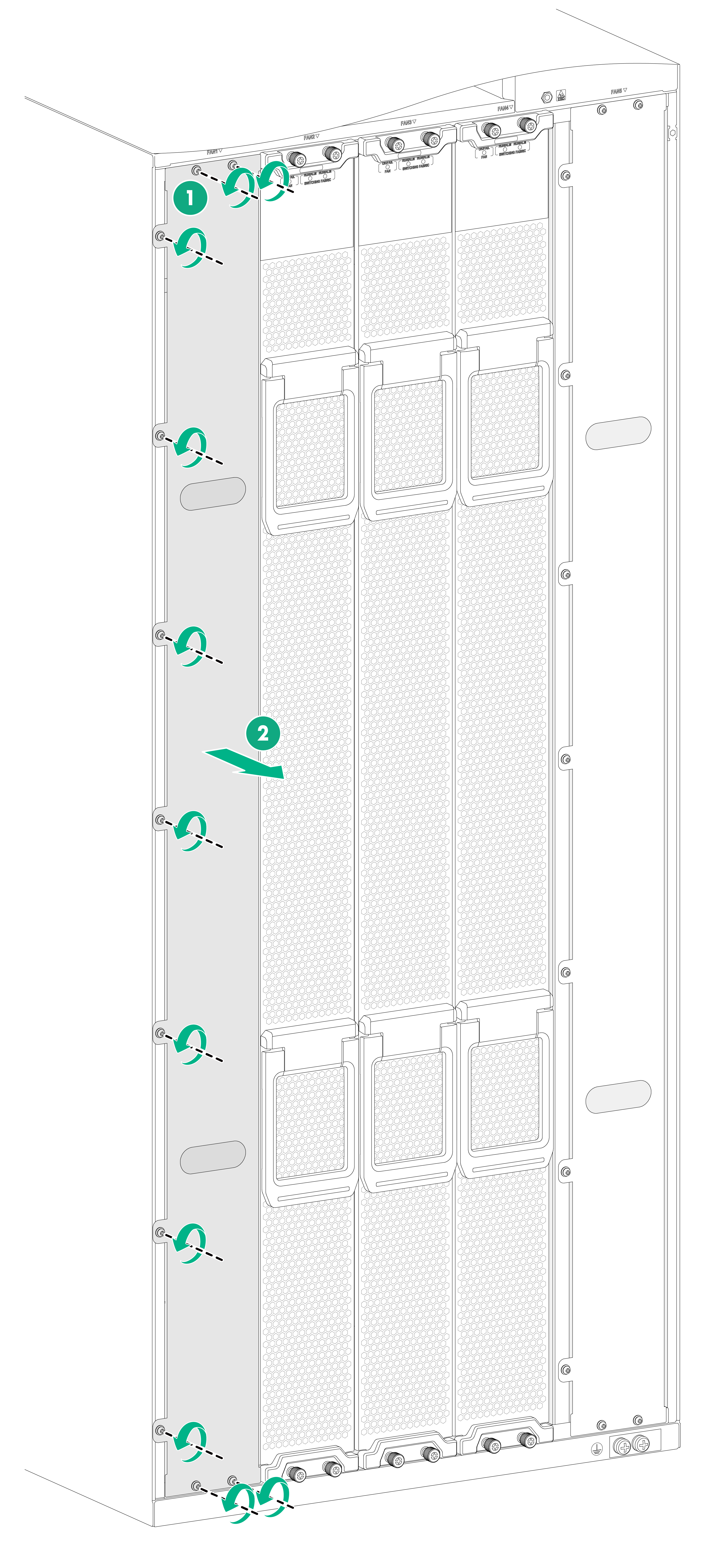
1. As shown by callout 1 in Figure 3-13, loosen the M3 screws on the fan tray filler panel.
2. As shown by callout 2 in Figure 3-13, put your fingers into the holes of the filler panel, and then pull the filler panel out.
Keep the removed filler panel secure for future use.
Figure 3-13 Removing the filler panel from a fan tray slot
Installing power supplies and power trays
Power trays and power supplies
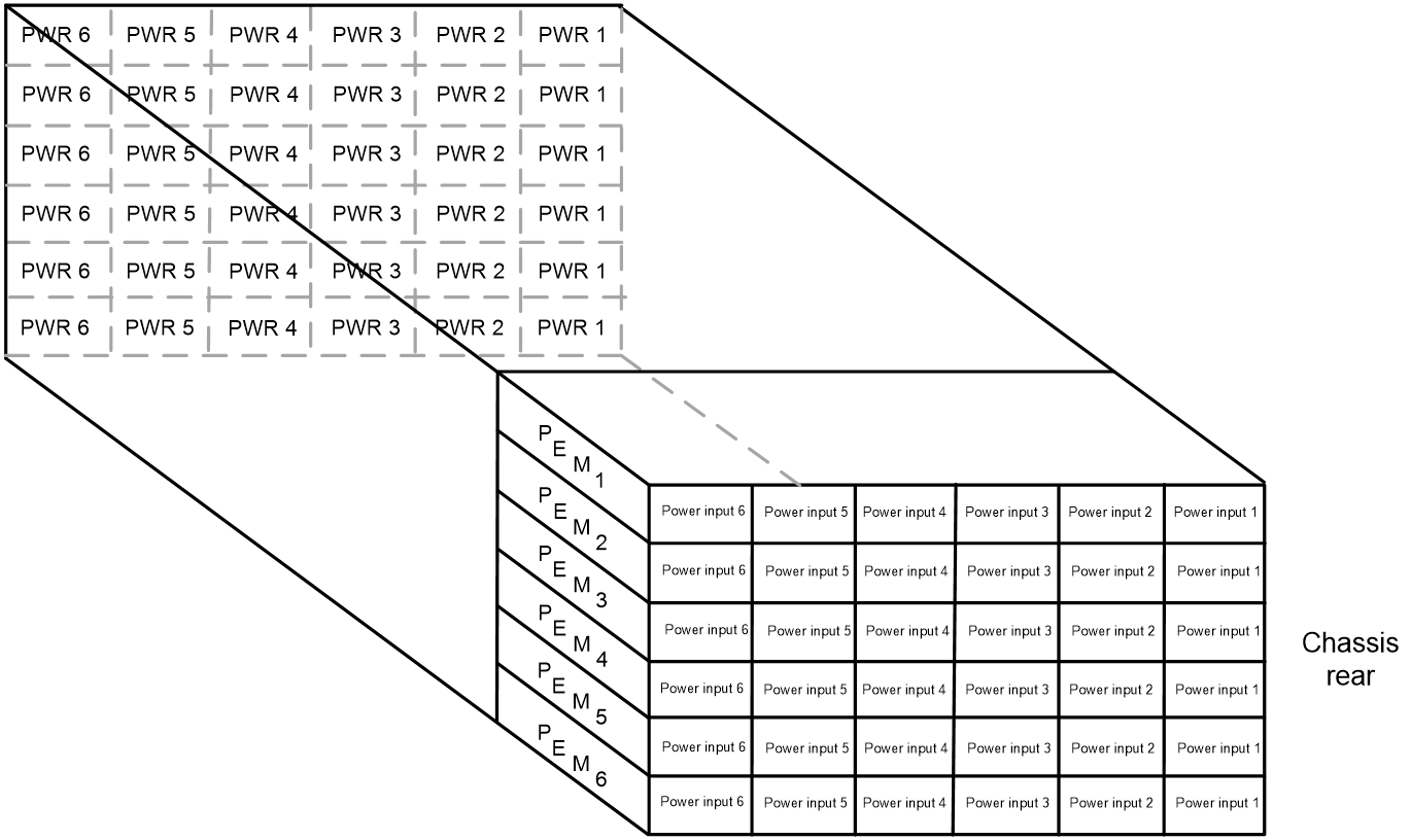
The power supplies are installed in the power trays. Power supplies at the front correspond to the power input ends at the rear as shown in Figure 3-14.
Figure 3-14 Power supplies and power input ends
Installing a power supply
1. Remove the filler panel from the target power supply slot.
Put your forefinger into the hole of the filler panel to hold and pull out the filler panel along the guide rails, as shown in Figure 3-15.
Figure 3-15 Removing a filler panel
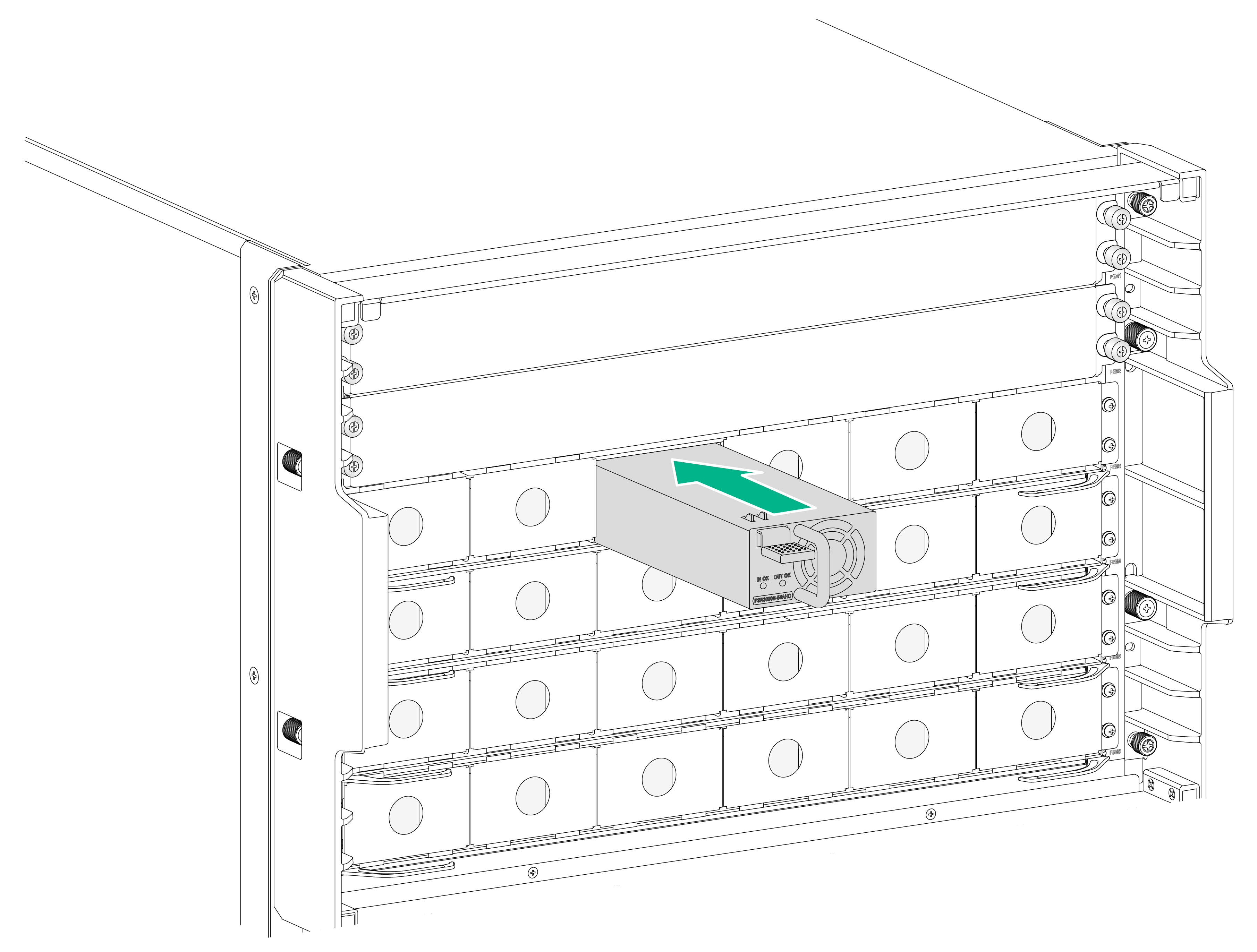
2. Align the power supply with the power supply slot. Then slide the power supply along the guide rails into the slot until the latch locks the power supply in place, as shown in Figure 3-16.
Figure 3-16 Installing a power supply
Connecting power cords
|
|
WARNING! Make sure each power cord has a separate circuit breaker. |
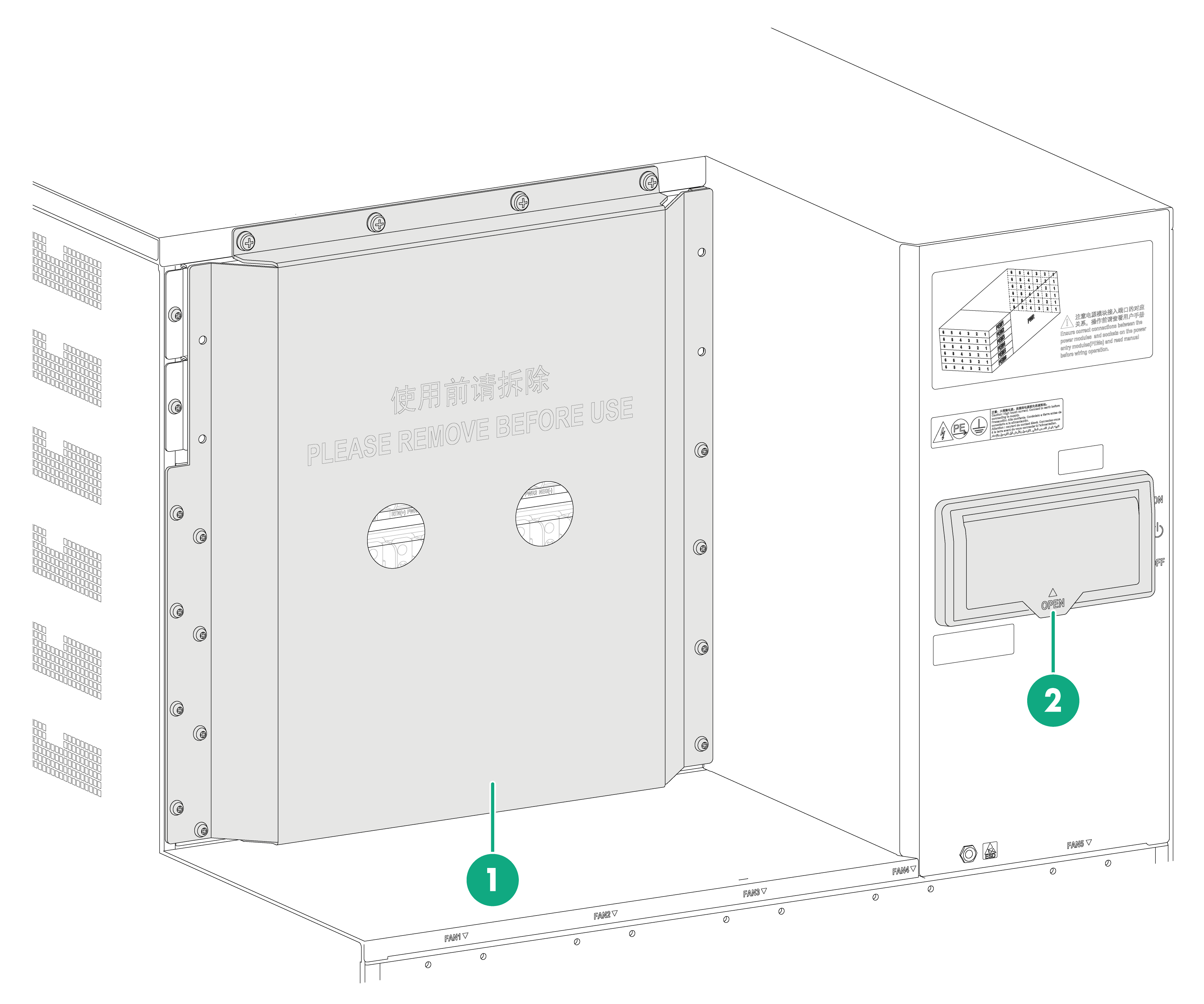
Before connecting a power cord, perform the following tasks:
· Remove the protective plate over the power input area.
· Turn off the circuit breaker at the power input end of the power cord and the power switch on the device.
Figure 3-17 Protective plate and power switch
|
(1) Protective plate over the power input area |
(2) Power switch |
Connecting an AC power cord
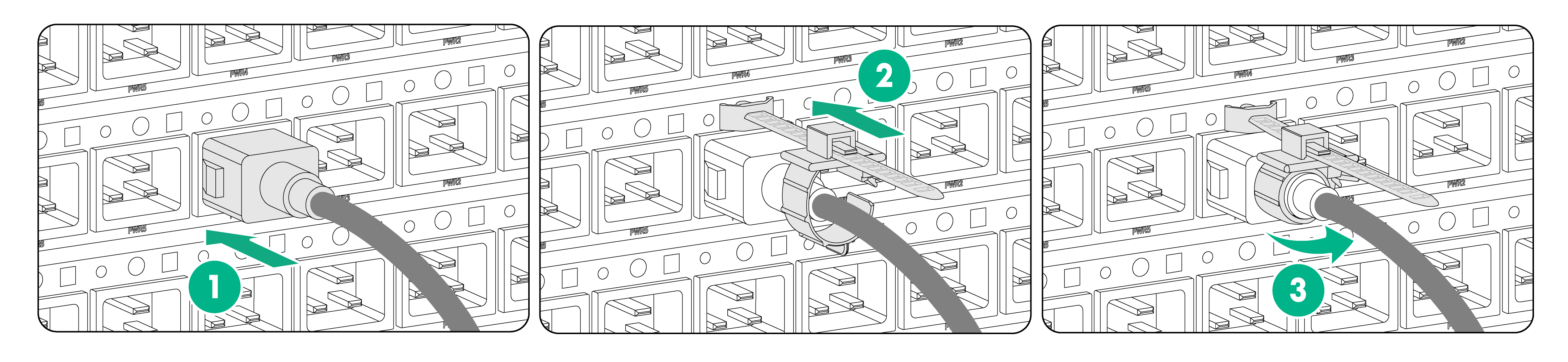
1. Connect the AC power cord connector to the AC input receptacle on the power tray, as shown by callout 1 in Figure 3-18.
2. Attach a cable clamp to the power tray. Release the tab on the tie mount and then slide the cable clamp forward until it is flush against the edge of the connector, as shown by callout 2 in Figure 3-18.
3. Close the cable clamp, as shown by callout 3 in Figure 3-18.
4. Connect the other end of the AC power cord to an AC power source.
Figure 3-18 Connecting an AC power cord
Connecting a DC power cord
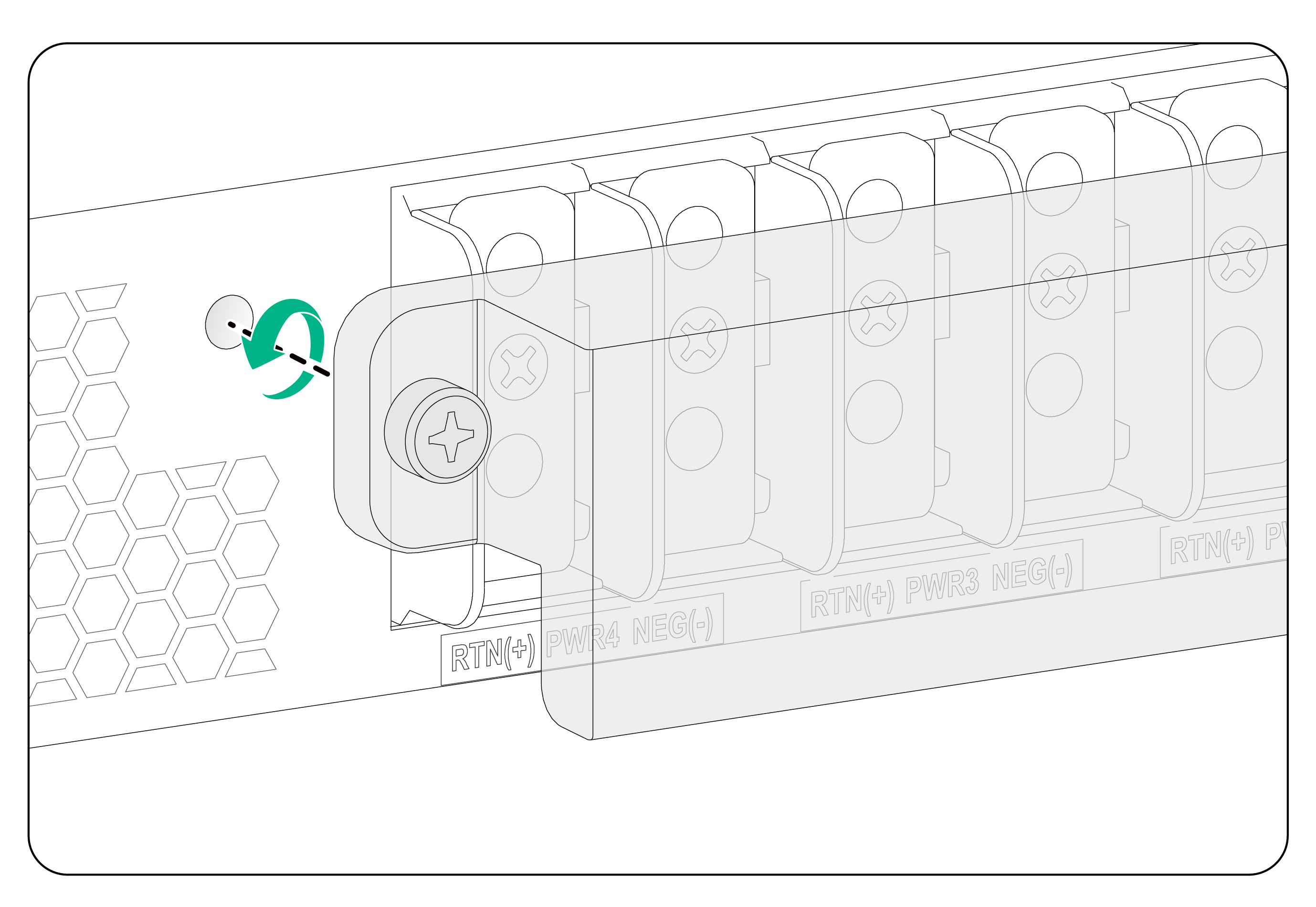
1. Remove the cover on the power tray, as shown in Figure 3-19.
Keep the removed cover secure and reinstall it after connecting the power cord.
Figure 3-19 Removing the cover from the power tray
2. Remove the screws on the terminal blocks.
3. Use the screws to connect the black wires to the positive terminals marked with RTN(+) and the blue wires to the negative terminals marked with NEG(–), as shown in Figure 3-20.
Figure 3-20 Connecting DC power cords to the DC terminal blocks
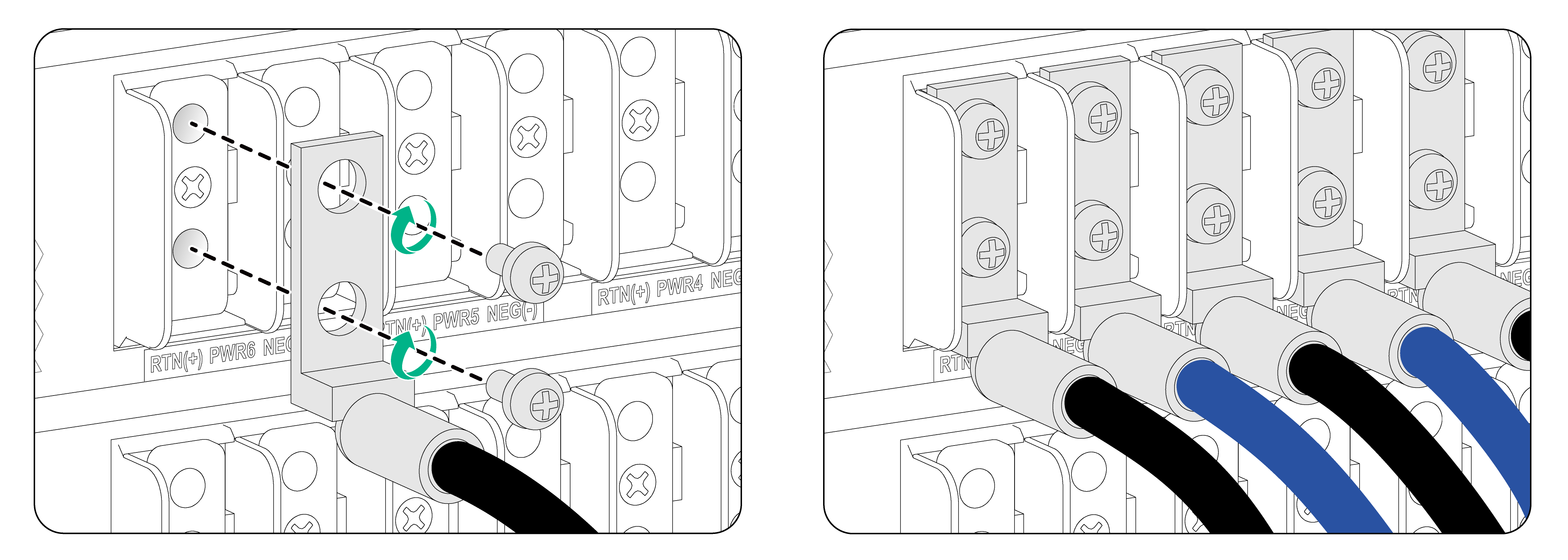
4. Connect the other end of the power cord to a DC power source.
Connect the blue wires to the negative terminals marked with –48V and the black wires to the positive terminals marked with RTN(+).
5. Reinstall the cover on the power tray and then use a Phillips screwdriver to fasten the captive screws.
(Optional) Installing power trays
The device comes with four power trays installed. You can install more power trays on it.
To install a power tray:
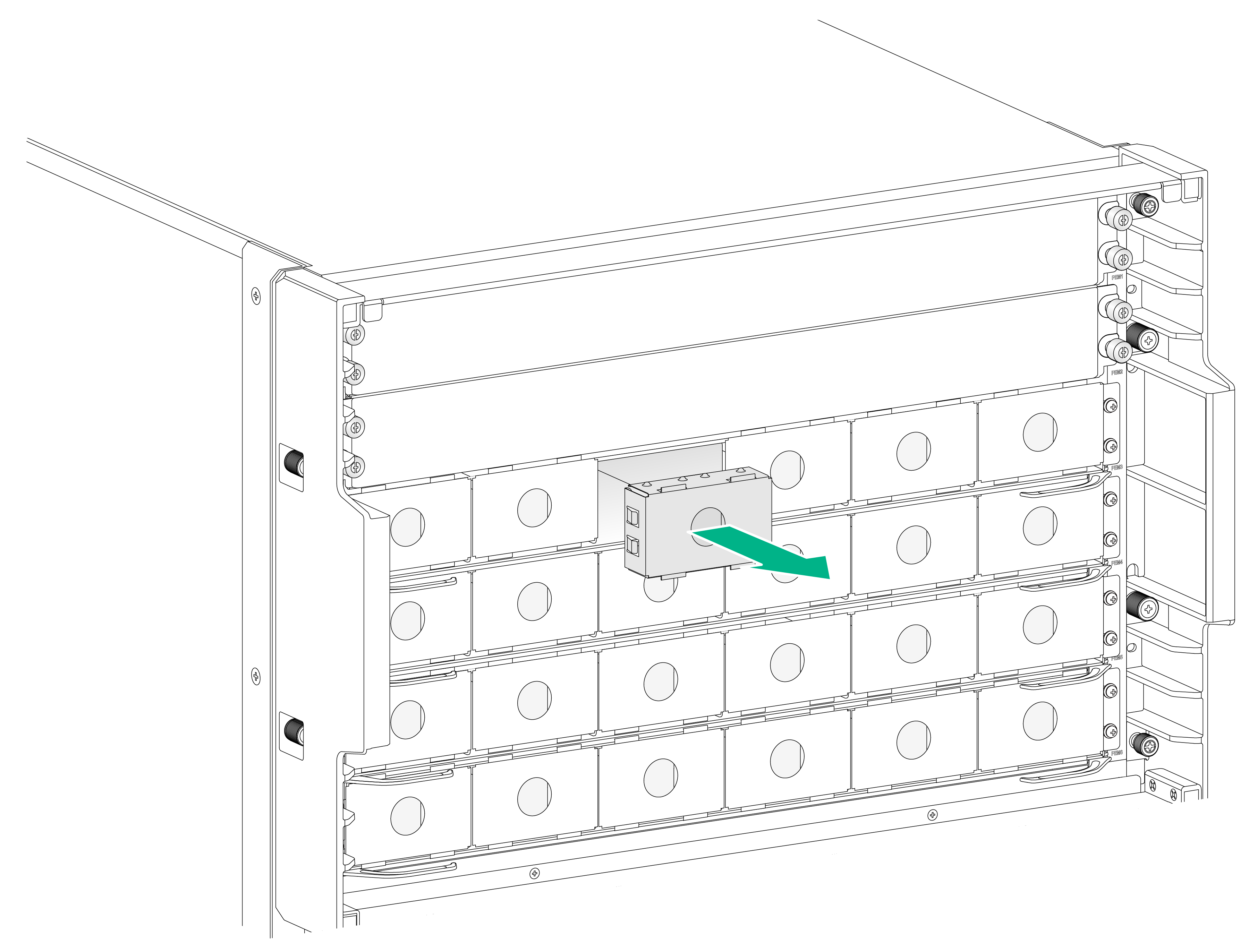
1. As shown in Figure 3-21 and Figure 3-22, remove the front and rear filler panels from the target power tray slot.
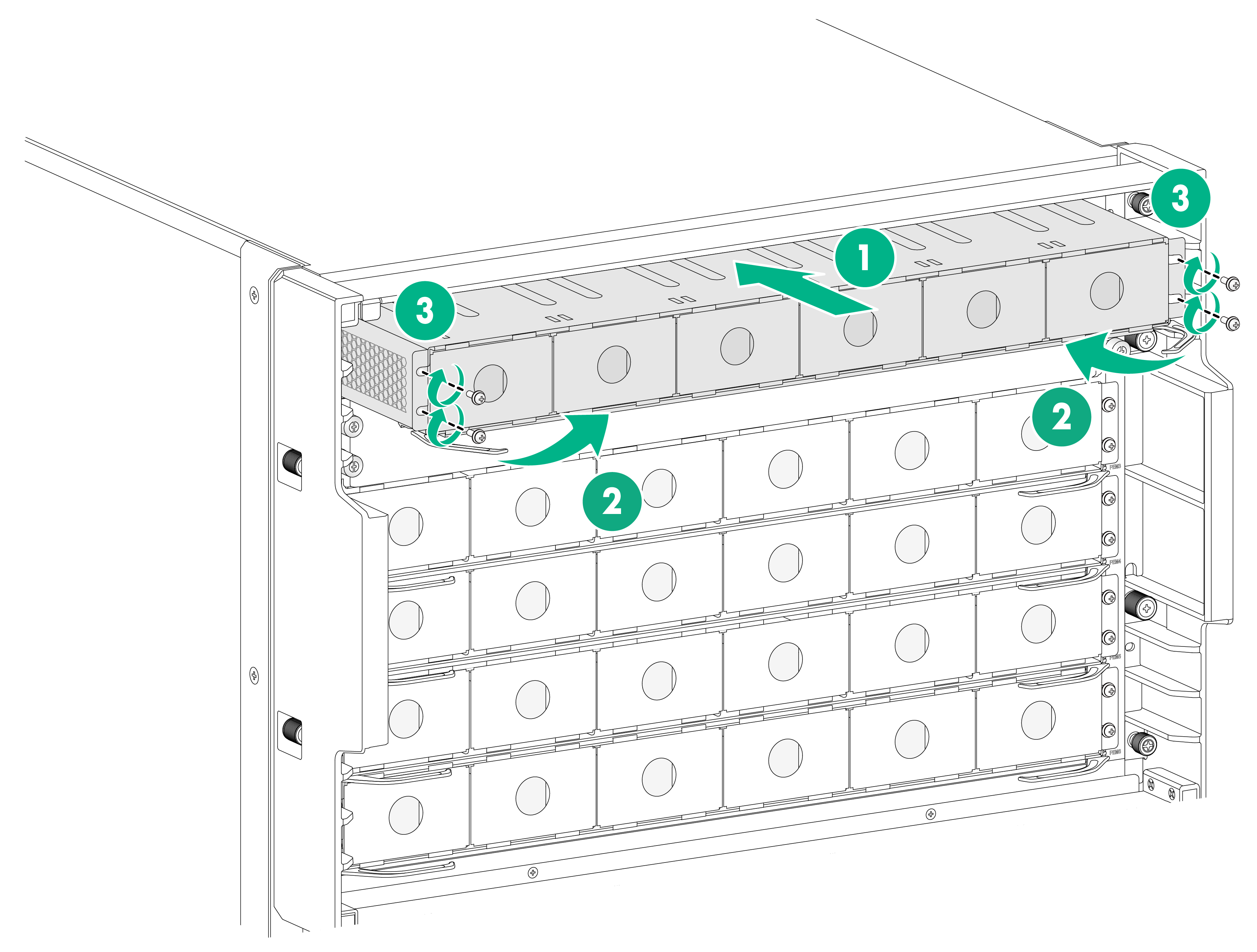
2. As shown by callout 1 in Figure 3-23, hold both sides of the power tray with two hands, and insert the power tray into the slot along the guide rails slowly and steadily.
3. As shown by callout 2 in Figure 3-23, close the ejector levers when the ejector levers touch the slot edges tightly.
4. As shown by callout 3 in Figure 3-23, use a screwdriver to fasten the screws on the power tray.
As a best practice, use a torque of 5 kgf-cm (0.49 Nm) to fasten the screws.
Figure 3-21 Removing a front filler panel from a power tray slot
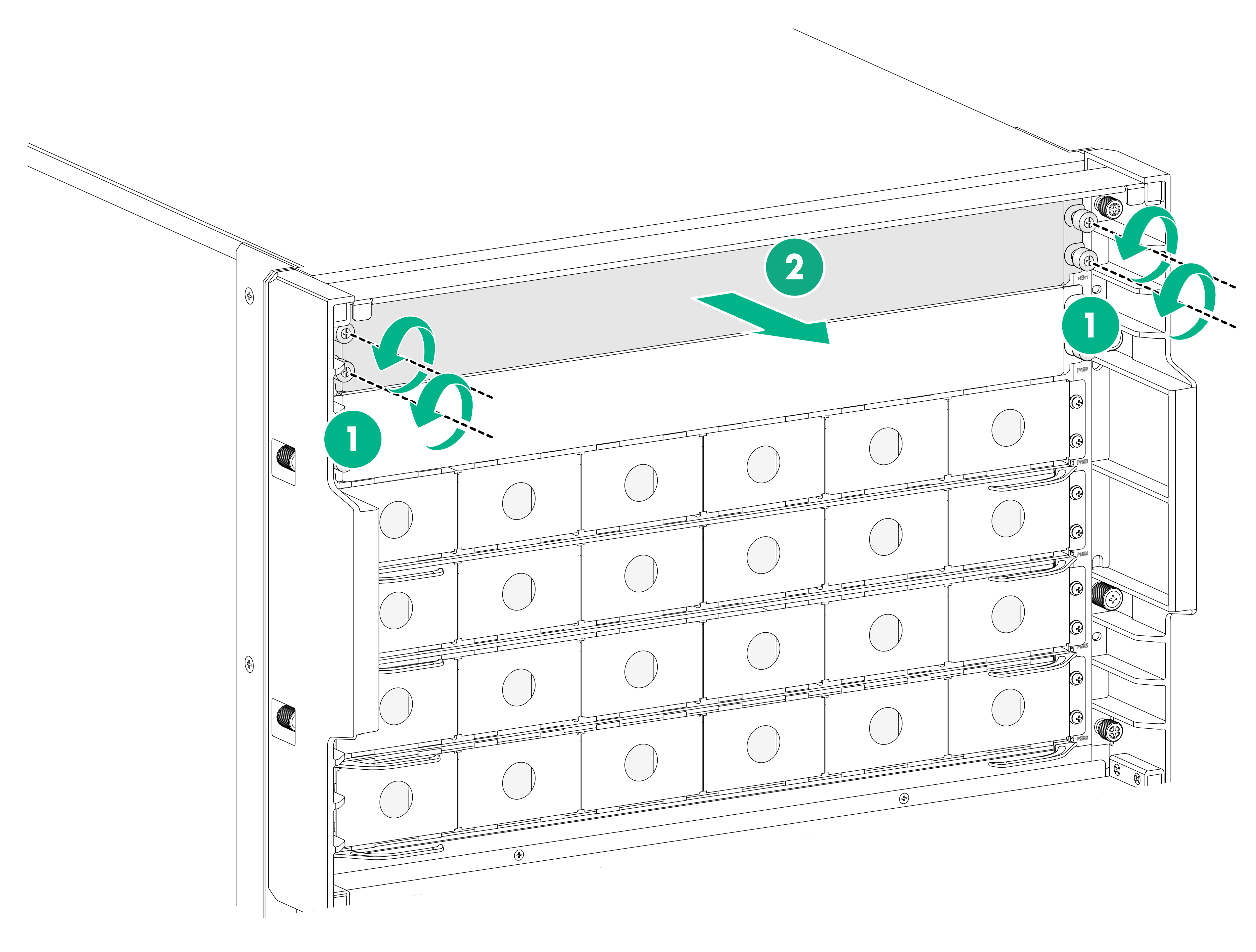
Figure 3-22 Removing a rear filler panel from a power tray slot
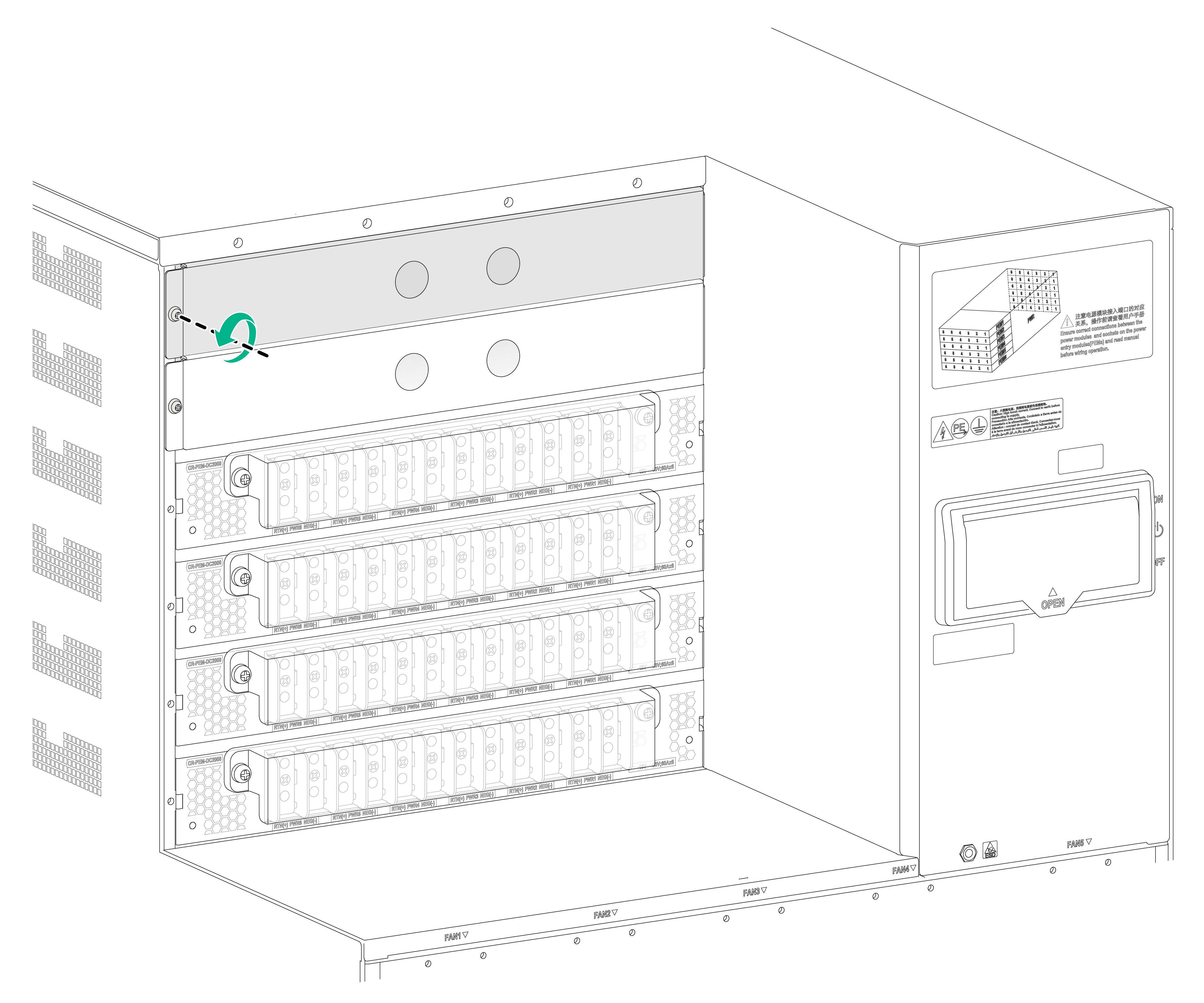
Figure 3-23 Installing a power tray
Installing the air filter in the top hood
The device comes with the top hood installed. You only need to install the air filter in the top hood.
To install the air filter in the top hood:
1. Unpack the air filter.
2. Position the air filter over the top hood, and then push the air filter until it is seated into the top hood.
Figure 3-24 Air filter and top hood
|
(1) Top hood |
(2) Air filter |
Figure 3-25 Installing the air filter in the top hood
Installing transceiver modules
|
|
CAUTION: If you are not to use a fiber port or transceiver module, insert dust plugs into the port or module. If you are not to connect an optical fiber, install dust caps for the fiber connector. |
Installing a transceiver module
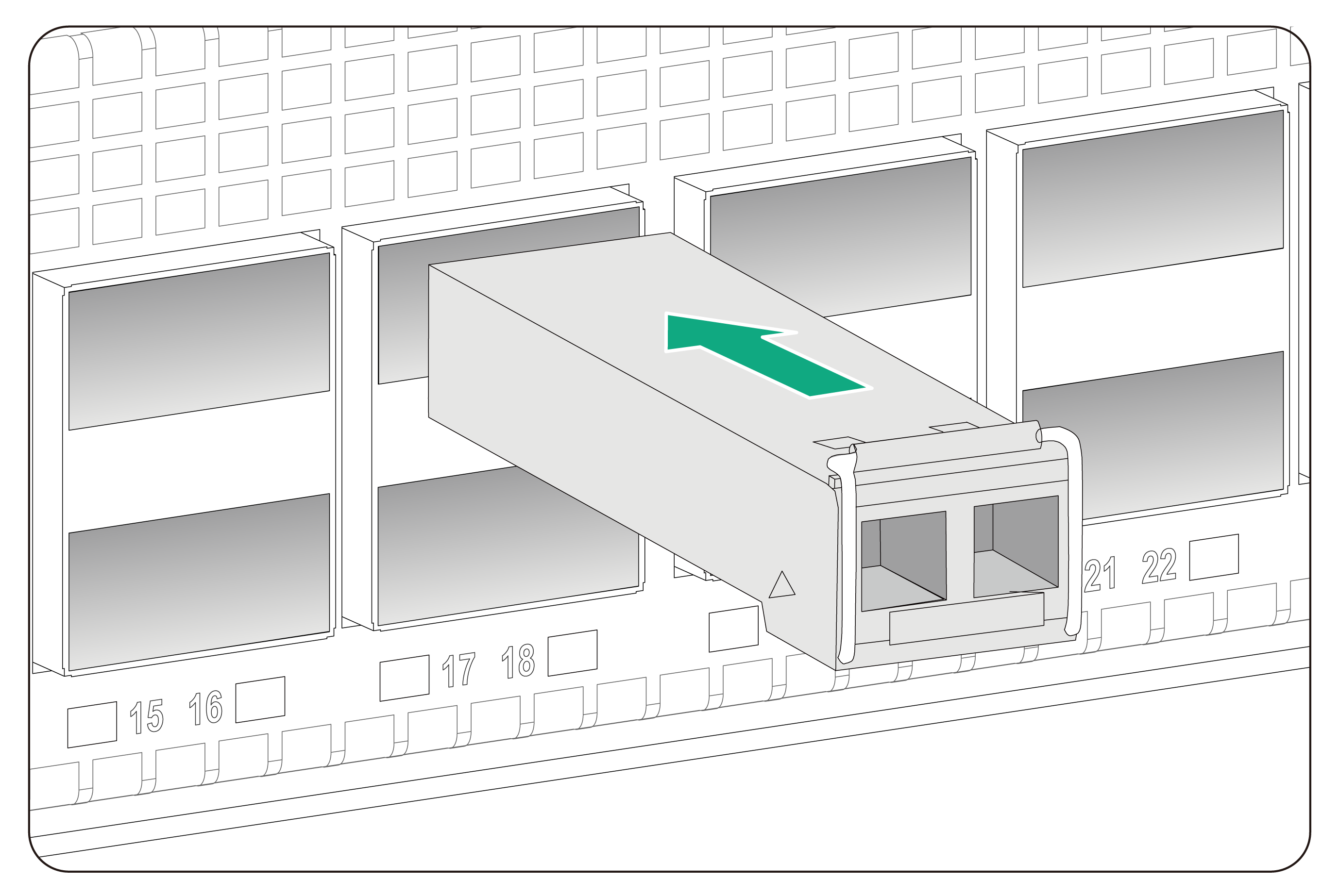
The transceiver modules are hot swappable.
To install a transceiver module:
1. Unpack the transceiver module.
Do not touch the golden plating of the transceiver module.
2. Pivot the clasp of the module up. Holding the transceiver module, gently push the transceiver module into the slot until it has firm contact with the slot, as shown in Figure 3-26.
Figure 3-26 Installing a transceiver module
|
|
NOTE: The types of transceiver modules supported by the device might change over time. For information about installing a transceiver module, see H3C Transceiver Modules and Network Cables Installation Guide. |
Connecting an interface cable
|
|
CAUTION: When you connect an interface cable, make sure the bend radius of the interface cable is no less than eight times the cable diameter. |
The interface cables are hot swappable.
To connect an interface cable:
1. Unpack the interface cable.
2. Correctly orient the interface cable connector and gently insert the connector into the target port. To be sure that the connector is seated securely in the port.
Transceiver modules and fiber ports have disorientation rejection designs. If you cannot insert a transceiver module easily into a port, the orientation might be wrong. Remove and reorient the transceiver module.
4 Cabling recommendations
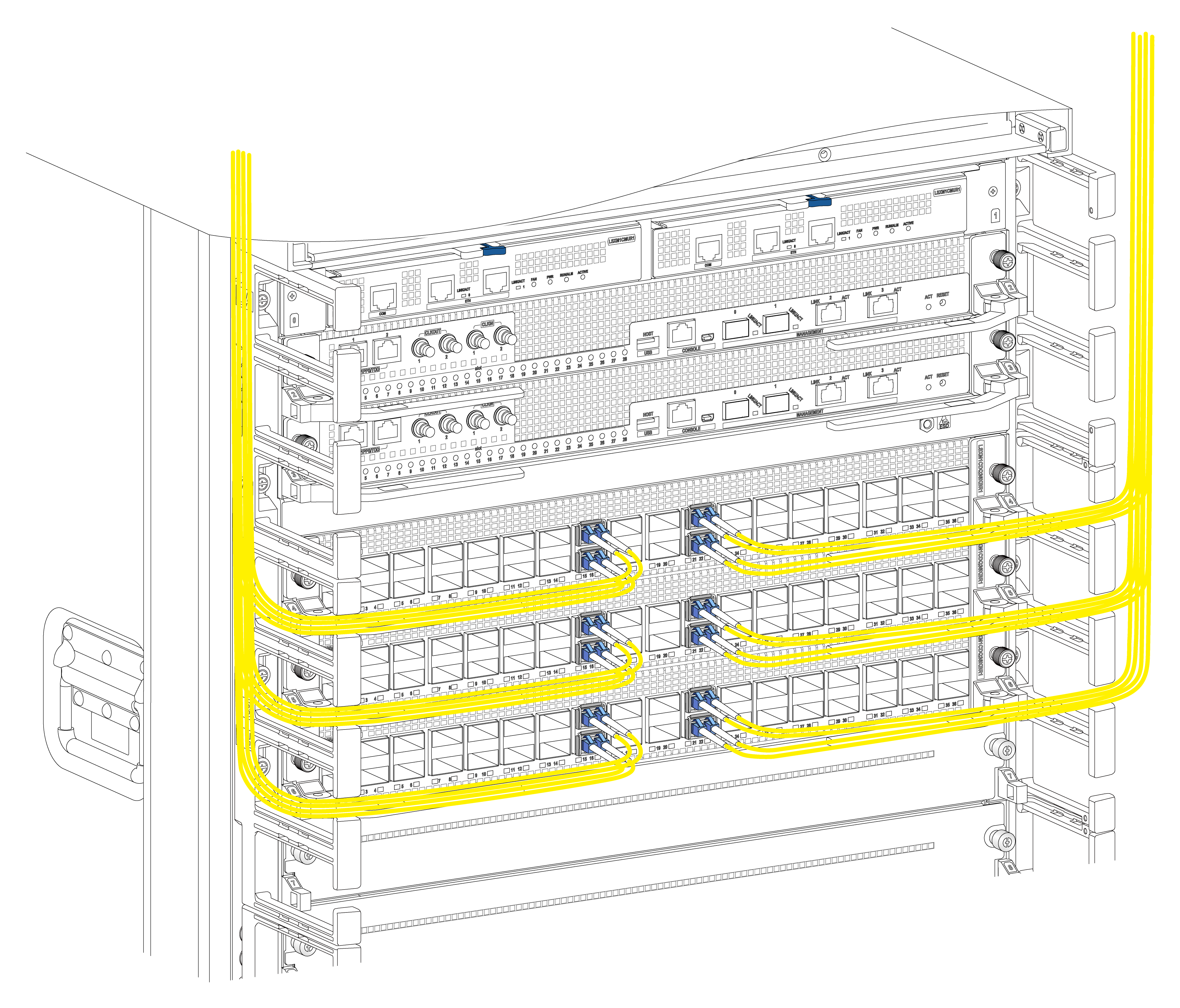
The cable management brackets are installed at the two sides of the chassis front panel. As a best practice, route network cables from the left and right sides, as shown in Figure 4-1.
Figure 4-1 Routing cables
5 Accessing the device
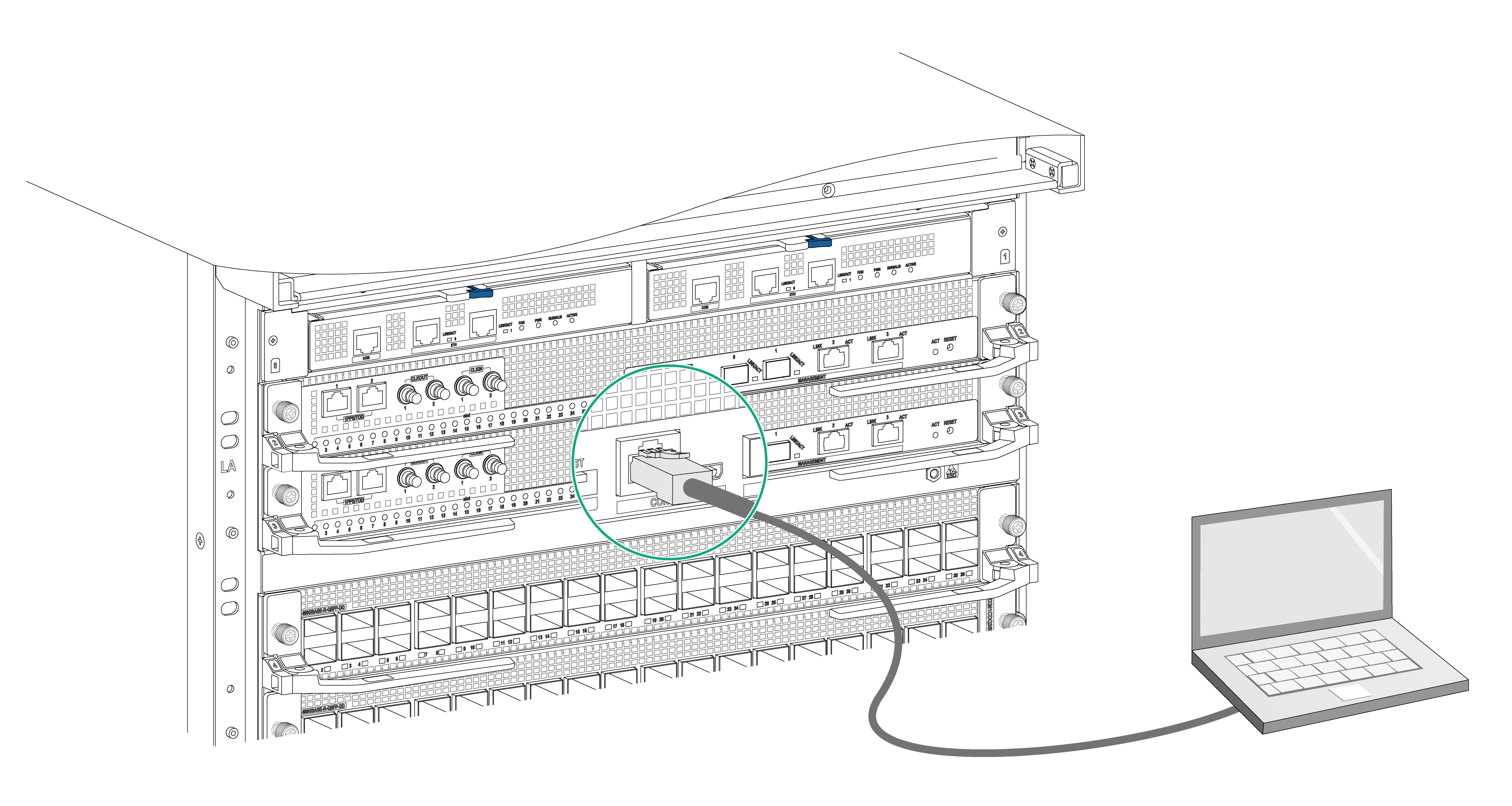
The first time you access the device you must use a console cable to connect a console terminal, for example, a PC, to the console port on the device.
Connecting the console cable
|
|
IMPORTANT: · Identify the mark on the console port and make sure you are connecting to the correct port. · The serial ports on PCs do not support hot swapping. If the device has been powered on, connect the console cable to the PC before connecting to the device, and when you disconnect the cable, first disconnect from the device. |
To connect the console cable:
1. Plug the DB-9 female connector of the console cable to the serial port of the PC.
2. Plug the RJ-45 connector of the console cable to the console port of the device.
Figure 5-1 Connecting a terminal to the console port
Verification before login
Before you log in to the device, perform the following tasks:
· Verify that the device has been correctly installed.
· Verify that all cards have been correctly installed.
· Verify that all the network cables, fibers, power cables, and grounding cables have been correctly connected.
· Verify that the voltage of the power source is as required.
· Verify that the console cable has been correctly connected, the terminal or PC used for configuration has started, and the configuration parameters have been set.
· Verify that the switch of the external power supply system and the power switch on the device are both turned on.
Viewing device startup information
After the device is powered on, the configuration terminal output startup information. The output information varies by software versions.
The following shows a sample output you will see when the device starts up:
System is starting...
Press Ctrl+D to access BASIC-BOOTWARE MENU...
Press Ctrl+T to start memory test
Booting Normal Extended BootWare
The Extended BootWare is self-decompressing..........Done.
...
System image is starting...
Line aux0 is available.
Press ENTER to get started.
Press Enter at the prompt. When the prompt <Sysname> appears, you can configure the device.
After the device finishes startup, verify the following items:
· The cooling system is working, and you can hear fan rotating noise and feel air being blown out.
· The LEDs on the SEUs show that the system is operating correctly. For more information about LEDs, see H3C S12500CR Switch Router Series Hardware Reference.
