- Table of Contents
-
- 12-Security Configuration Guide
- 00-Preface
- 01-AAA configuration
- 02-User profile configuration
- 03-Password control configuration
- 04-Keychain configuration
- 05-Public key management
- 06-PKI configuration
- 07-IPsec configuration
- 08-SSH configuration
- 09-SSL configuration
- 10-Session management
- 11-Attack detection and prevention configuration
- 12-IP-based attack prevention configuration
- 13-ARP attack protection configuration
- 14-ND attack defense configuration
- 15-uRPF configuration
- 16-Crypto engine configuration
- Related Documents
-
| Title | Size | Download |
|---|---|---|
| 07-IPsec configuration | 362.67 KB |
Contents
IPv6 routing protocol-based IPsec
Restrictions and guidelines: IPsec configuration
Configuring IPsec for IPv6 routing protocols
Configuring IPsec for tunnel interfaces
Configuring an IPsec transform set
Configuring and applying a manual IPsec profile
Manual IPsec profile configuration and application tasks at a glance
Configuring a manual IPsec profile
Applying the IPsec profile to an IPv6 routing protocol
Configuring and applying an IKE-based IPsec profile
IKE-based IPsec profile configuration and application tasks at a glance
Configuring an IKE-based IPsec profile
Applying an IKE-based IPsec profile to a tunnel interface
Configuring IPsec fragmentation
Setting the maximum number of IPsec tunnels
Configuring the global IPsec SA lifetime and idle timeout
Configuring the DF bit of IPsec packets
Enabling logging for IPsec packets
Configuring SNMP notifications for IPsec
Display and maintenance commands for IPsec
Example: Configuring IPsec for RIPng
Example: Configuring IPsec tunnel interface-based IPsec for IPv4 packets
Relationship between IPsec and IKE
Prerequisites for IKE configuration
Configuring peer IDs for the IKE profile
Specifying the IKE keychain or PKI domain
Configuring the IKE phase 1 negotiation mode
Specifying IKE proposals for the IKE profile
Configuring the local ID for the IKE profile
Configuring optional features for the IKE profile
Configuring the global identity information
Configuring the IKE keepalive feature
Configuring the IKE NAT keepalive feature
Setting the maximum number of IKE SAs
Configuring SNMP notifications for IKE
Display and maintenance commands for IKE
IKE negotiation failed because no matching IKE proposals were found
IKE negotiation failed because no IKE proposals or IKE keychains are specified correctly
Configuring IPsec
About IPsec
IP Security (IPsec) is defined by the IETF to provide interoperable, high-quality, cryptography-based security for IP communications. It is a Layer 3 VPN technology that transmits data in a secure channel established between two endpoints (such as two security gateways). Such a secure channel is usually called an IPsec tunnel.
IPsec framework
IPsec is a security framework that has the following protocols and algorithms:
· Authentication Header (AH).
· Encapsulating Security Payload (ESP).
· Internet Key Exchange (IKE).
· Algorithms for authentication and encryption.
AH and ESP are security protocols that provide security services. IKE performs automatic key exchange. For more information about IKE, see "Configuring IKE."
IPsec security services
IPsec provides the following security services for data packets in the IP layer:
· Confidentiality—The sender encrypts packets before transmitting them over the Internet, protecting the packets from being eavesdropped en route.
· Data integrity—The receiver verifies the packets received from the sender to make sure they are not tampered with during transmission.
· Data origin authentication—The receiver verifies the authenticity of the sender.
· Anti-replay—The receiver examines packets and drops outdated and duplicate packets.
Benefits of IPsec
IPsec delivers the following benefits:
· Reduced key negotiation overhead and simplified maintenance by supporting the IKE protocol. IKE provides automatic key negotiation and automatic IPsec security association (SA) setup and maintenance.
· Good compatibility. You can apply IPsec to all IP-based application systems and services without modifying them.
· Encryption on a per-packet rather than per-flow basis. Per-packet encryption allows for flexibility and greatly enhances IP security.
Security protocols
IPsec comes with two security protocols, AH and ESP. They define how to encapsulate IP packets and the security services that they can provide.
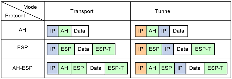
· AH (protocol 51) defines the encapsulation of the AH header in an IP packet, as shown in Figure 3. AH can provide data origin authentication, data integrity, and anti-replay services to prevent data tampering, but it cannot prevent eavesdropping. Therefore, it is suitable for transmitting non-confidential data. AH supports authentication algorithms HMAC-MD5 and HMAC-SHA1.
· ESP (protocol 50) defines the encapsulation of the ESP header and trailer in an IP packet, as shown in Figure 3. ESP can provide data encryption, data origin authentication, data integrity, and anti-replay services. Unlike AH, ESP can guarantee data confidentiality because it can encrypt the data before encapsulating the data to IP packets. ESP supports encryption algorithms such as DES, 3DES, and AES, and authentication algorithms HMAC-MD5 and HMAC-SHA1.
Both AH and ESP provide authentication services, but the authentication service provided by AH is stronger. In practice, you can choose either or both security protocols. When both AH and ESP are used, an IP packet is encapsulated first by ESP and then by AH.
Encapsulation modes
IPsec supports the following encapsulation modes: transport mode and tunnel mode.
Transport mode
The security protocols protect the upper layer data of an IP packet. Only the transport layer data is used to calculate the security protocol headers. The calculated security protocol headers and the encrypted data (only for ESP encapsulation) are placed after the original IP header. You can use the transport mode when end-to-end security protection is required (the secured transmission start and end points are the actual start and end points of the data). The transport mode is typically used for protecting host-to-host communications, as shown in Figure 1.
Figure 1 IPsec protection in transport mode

Tunnel mode
The security protocols protect the entire IP packet. The entire IP packet is used to calculate the security protocol headers. The calculated security protocol headers and the encrypted data (only for ESP encapsulation) are encapsulated in a new IP packet. In this mode, the encapsulated packet has two IP headers. The inner IP header is the original IP header. The outer IP header is added by the network device that provides the IPsec service. You must use the tunnel mode when the secured transmission start and end points are not the actual start and end points of the data packets (for example, when two gateways provide IPsec but the data start and end points are two hosts behind the gateways). The tunnel mode is typically used for protecting gateway-to-gateway communications, as shown in Figure 2.
Figure 2 IPsec protection in tunnel mode

Figure 3 shows how the security protocols encapsulate an IP packet in different encapsulation modes.
Figure 3 Security protocol encapsulations in different modes
Security association
A security association (SA) is an agreement negotiated between two communicating parties called IPsec peers. An SA includes the following parameters for data protection:
· Security protocols (AH, ESP, or both).
· Encapsulation mode (transport mode or tunnel mode).
· Authentication algorithm (HMAC-MD5 or HMAC-SHA1).
· Encryption algorithm (DES, 3DES, or AES).
· Shared keys and their lifetimes.
An SA is unidirectional. At least two SAs are needed to protect data flows in a bidirectional communication. If two peers want to use both AH and ESP to protect data flows between them, they construct an independent SA for each protocol in each direction.
An SA is uniquely identified by a triplet, which consists of the security parameter index (SPI), destination IP address, and security protocol identifier. An SPI is a 32-bit number. It is transmitted in the AH/ESP header.
An SA can be set up manually or through IKE.
· Manual mode—Configure all parameters for the SA through commands. This configuration mode is complex and does not support some advanced features (such as periodic key update), but it can implement IPsec without IKE. This mode is mainly used in small and static networks or when the number of IPsec peers in the network is small.
· IKE negotiation mode—The peers negotiate and maintain the SA through IKE. This configuration mode is simple and has good expansibility. As a best practice, set up SAs through IKE negotiations in medium- and large-scale dynamic networks.
A manually configured SA never ages out. An IKE-created SA has a lifetime, which comes in two types:
· Time-based lifetime—Defines how long the SA can be valid after it is created.
· Traffic-based lifetime—Defines the maximum traffic that the SA can process.
If both lifetime timers are configured for an SA, the SA becomes invalid when either of the lifetime timers expires. Before the SA expires, IKE negotiates a new SA, which takes over immediately after its creation.
Authentication and encryption
Authentication algorithms
IPsec uses hash algorithms to perform authentication. A hash algorithm produces a fixed-length digest for an arbitrary-length message. IPsec peers respectively calculate message digests for each packet. The receiver compares the local digest with that received from the sender. If the digests are identical, the receiver considers the packet intact and the sender's identity valid. IPsec uses the Hash-based Message Authentication Code (HMAC) based authentication algorithms, including HMAC-MD5 and HMAC-SHA1. Compared with HMAC-SHA1, HMAC-MD5 is faster but less secure.
Encryption algorithms
IPsec uses symmetric encryption algorithms, which encrypt and decrypt data by using the same keys. The following encryption algorithms are available for IPsec on the device:
· DES—Encrypts a 64-bit plaintext block with a 56-bit key. DES is the least secure but the fastest algorithm.
· 3DES—Encrypts plaintext data with three 56-bit DES keys. The key length totals up to 168 bits. It provides moderate security strength and is slower than DES.
· AES—Encrypts plaintext data with a 128-bit, 192-bit, or 256-bit key. AES provides the highest security strength and is slower than 3DES.
Crypto engine
The IPsec feature is resource intensive for its complex encryption/decryption and authentication algorithms. To improve processing performance, you can use crypto engine to offload IPsec tasks.
The crypto engine processes all IPsec protected packets and hands the processed packets back to the device for forwarding.
For more information about crypto engines, see "Configuring crypto engines."
IPsec-protected traffic
IPsec tunnels can protect the following types of traffic:
· Packets that match specific ACLs.
· Packets routed to a tunnel interface.
· Packets of IPv6 routing protocols.
Two peers use security policies (IPsec profiles) to protect packets between them. A security policy defines the range of packets to be protected by IPsec and the security parameters used for the protection. For more information about IPsec profiles, see "IPsec profile."
The following information describes how IPsec protects packets:
· When an IPsec peer identifies the packets to be protected according to the security policy, it sets up an IPsec tunnel and sends the packet to the remote peer through the tunnel. The IPsec tunnel can be manually configured beforehand, or it can be set up through IKE negotiation triggered by the packet. The IPsec tunnels are actually the IPsec SAs. The inbound packets are protected by the inbound SA, and the outbound packets are protected by the outbound SA.
· When the remote IPsec peer receives the packet, it drops, de-encapsulates, or directly forwards the packet according to the configured security policy.
Tunnel interface-based IPsec
To implement tunnel interface-based IPsec, configure an IPsec profile and apply the IPsec profile to a tunnel interface. All traffic routed to the tunnel interface, including multicast traffic, is protected by IPsec. Tunnel interface-based IPsec supports only the tunnel encapsulation mode.
For tunnel interface-based IPsec, packet encapsulation and decapsulation are performed on the tunnel interfaces.
Figure 4 Tunnel interface encapsulation
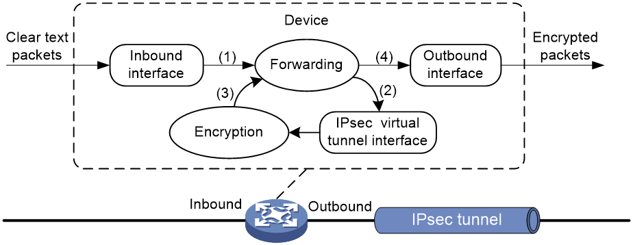
As shown in Figure 4, a tunnel interface encapsulates an IP packet as follows:
1. Upon receiving a clear text packet, the inbound interface sends the packet to the service module for encryption.
2. The device sends the encrypted packet back to the forwarding module.
3. The forwarding module looks up the routing table according to the destination IP address in the new IP header and sends the packet out of the physical output interface of the tunnel interface
Figure 5 Tunnel interface de-encapsulation
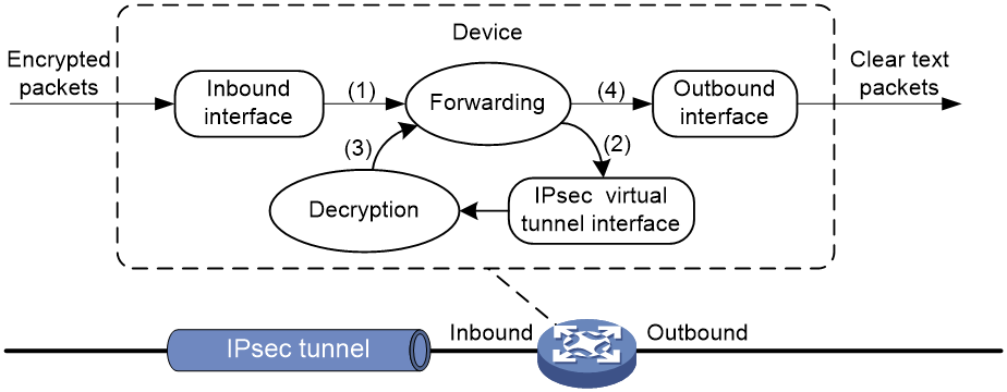
As shown in Figure 5, a tunnel interface de-encapsulates an IP packet as follows:
4. Upon receiving an encrypted packet, the inbound interface sends the packet to the service module for decryption.
5. The device sends the decrypted packet to the forwarding module.
6. The forwarding module looks up the routing table according to the destination address in the clear text packet and sends the packet out of the physical output interface of the tunnel interface.
IPv6 routing protocol-based IPsec
You can implement IPv6 routing protocol-based IPsec by binding an IPsec profile to an IPv6 routing protocol. All packets of the protocol are encapsulated with IPsec. Supported IPv6 routing protocols include OSPFv3, IPv6 BGP, and RIPng.
All packets of the applications that are not bound to IPsec and the IPsec packets that failed to be de-encapsulated are dropped.
In one-to-many communication scenarios, you must configure the IPsec SAs for an IPv6 routing protocol in manual mode because of the following reasons:
· The automatic key exchange mechanism protects communications between two points. In one-to-many communication scenarios, automatic key exchange cannot be implemented.
· One-to-many communication scenarios require that all the devices use the same SA parameters (SPI and key) to receive and send packets. IKE negotiated SAs cannot meet this requirement.
IPsec profile
IPsec profiles define the parameters used to establish IPsec tunnels between two peers and the range of packets to be protected.
IPsec profile
IPsec profiles can be classified into the following types:
· Manual IPsec profile—A manual IPsec profile is used to protect IPv6 routing protocols. It specifies the IPsec transform set used for protecting data flows, and the SPIs and keys used by the SAs.
· IKE-based IPsec profile—An IKE-based IPsec profile is applied to tunnel interfaces to protect tunneled traffic. It specifies the IPsec transform sets used for protecting data flows, and the IKE profile used for IKE negotiation.
Protocols and standards
· RFC 2401, Security Architecture for the Internet Protocol
· RFC 2402, IP Authentication Header
· RFC 2406, IP Encapsulating Security Payload
· RFC 4552, Authentication/Confidentiality for OSPFv3
Restrictions and guidelines: IPsec configuration
Typically, IKE uses UDP port 500 for communication, and AH and ESP use the protocol numbers 51 and 50, respectively. Make sure traffic of these protocols is not denied on the interfaces with IKE or IPsec configured.
IPsec tasks at a glance
Configuring IPsec for IPv6 routing protocols
To configure IPsec protection for IPv6 routing protocols, perform the following tasks:
1. Configuring an IPsec transform set
2. Configuring and applying a manual IPsec profile
3. (Optional.) Configuring accessibility features
¡ Configuring IPsec fragmentation
¡ Setting the maximum number of IPsec tunnels
¡ Configuring the global IPsec SA lifetime and idle timeout
¡ Configuring IPsec anti-replay
¡ Configuring the DF bit of IPsec packets
4. (Optional.) Configuring logging and SNMP notification for IPsec.
¡ Enabling logging for IPsec packets
¡ Configuring SNMP notifications for IPsec
Configuring IPsec for tunnel interfaces
To configure IPsec protection for tunnel interfaces, perform the following tasks:
1. Configuring an IPsec transform set
2. Configuring and applying an IKE-based IPsec profile
3. (Optional.) Configuring accessibility features
¡ Configuring IPsec fragmentation
¡ Setting the maximum number of IPsec tunnels
¡ Configuring the global IPsec SA lifetime and idle timeout
¡ Configuring IPsec anti-replay
¡ Configuring the DF bit of IPsec packets
4. (Optional.) Configuring logging and SNMP notification for IPsec.
¡ Enabling logging for IPsec packets
¡ Configuring SNMP notifications for IPsec
Configuring an IPsec transform set
About this task
An IPsec transform set, part of an IPsec profile, defines the security parameters for IPsec SA negotiation, including the security protocol, encryption algorithms, and authentication algorithms.
Restrictions and guidelines
Changes to an IPsec transform set affect only SAs negotiated after the changes. To apply the changes to existing SAs, execute the reset ipsec sa command to clear the SAs so that they can be set up by using the updated parameters.
The transport mode applies only when the source and destination IP addresses of data flows match those of the IPsec tunnel. IPsec transform sets used in IPsec profiles for IPv6 routing protocols support only the transport mode.
When you configure the Perfect Forward Secrecy (PFS) feature in an IPsec transform set, follow these guidelines:
· In IKEv1, the security level of the DH group of the initiator must be higher than or equal to that of the responder.
· The end without the PFS feature performs SA negotiation according to the PFS requirements of the peer end.
You can specify multiple authentication or encryption algorithms for the same security protocol. The algorithm specified earlier has a higher priority.
Procedure
1. Enter system view.
system-view
2. Create an IPsec transform set and enter its view.
ipsec transform-set transform-set-name
3. Specify the security protocol for the IPsec transform set.
protocol { ah | ah-esp | esp }
By default, the ESP security protocol is used.
4. Specify the encryption algorithms for ESP. Skip this step if the protocol ah command is configured.
esp encryption-algorithm { 3des-cbc | aes-cbc-128 | aes-cbc-192 | aes-cbc-256 | des-cbc | null | sm4-cbc } *
By default, no encryption algorithm is specified for ESP.
5. Specify the authentication algorithms for ESP. Skip this step if the protocol ah command is configured.
esp authentication-algorithm { md5 | sha1 | sha256 | sha384 | sha512 | sm3 } *
By default, no authentication algorithm is specified for ESP.
6. Specify the authentication algorithms for AH. Skip this step if the protocol esp command is configured.
ah authentication-algorithm { md5 | sha1 | sha256 | sha384 | sha512 | sm3 } *
By default, no authentication algorithm is specified for AH.
7. Specify the packet encapsulation mode.
encapsulation-mode { transport | tunnel }
By default, the security protocol encapsulates IP packets in tunnel mode.
8. (Optional.) Enable the PFS feature.
pfs { dh-group1 | dh-group2 | dh-group5 | dh-group14 | dh-group24 }
Configuring and applying a manual IPsec profile
Manual IPsec profile configuration and application tasks at a glance
1. Configuring a manual IPsec profile
2. Applying the IPsec profile to an IPv6 routing protocol
Configuring a manual IPsec profile
About this task
A manual IPsec profile specifies the IPsec transform set used for protecting data flows, and the SPIs and keys used by the SAs.
Restrictions and guidelines
When you configure a manual IPsec profile, make sure the IPsec profile configuration at both tunnel ends meets the following requirements:
· The IPsec transform set specified in the IPsec profile at the two tunnel ends must have the same security protocol, encryption and authentication algorithms, and packet encapsulation mode.
· The local inbound and outbound IPsec SAs must have the same SPI and key.
· The IPsec SAs on the devices in the same scope must have the same key. The scope is defined by protocols. For OSPFv3, the scope consists of OSPFv3 neighbors or an OSPFv3 area. For RIPng, the scope consists of directly-connected neighbors or a RIPng process. For BGP, the scope consists of BGP peers or a BGP peer group.
· The keys for the IPsec SAs at the two tunnel ends must be configured in the same format. For example, if the local end uses a key in hexadecimal format, the remote end must also use a key in hexadecimal format. If you configure a key in both the character and the hexadecimal formats, only the most recent configuration takes effect.
· If you configure a key in character format for ESP, the device automatically generates an authentication key and an encryption key for ESP.
Procedure
1. Enter system view.
system-view
2. Create a manual IPsec profile and enter its view.
ipsec profile profile-name manual
The manual keyword is not needed if you enter the view of an existing IPsec profile.
3. (Optional.) Configure a description for the IPsec profile.
description text
By default, no description is configured.
4. Specify an IPsec transform set.
transform-set transform-set-name
By default, no IPsec transform set is specified in an IPsec profile.
The specified IPsec transform set must use the transport mode.
5. Configure an SPI for an SA.
sa spi { inbound | outbound } { ah | esp } spi-number
By default, no SPI is configured for an SA.
6. Configure keys for the IPsec SA.
¡ Configure an authentication key in hexadecimal format for AH.
sa hex-key authentication { inbound | outbound } ah { cipher | simple } string
¡ Configure an authentication key in character format for AH.
sa string-key { inbound | outbound } ah { cipher | simple } string
¡ Configure a key in character format for ESP.
sa string-key { inbound | outbound } esp { cipher | simple } string
¡ Configure an authentication key in hexadecimal format for ESP.
sa hex-key authentication { inbound | outbound } esp { cipher | simple }
¡ Configure an encryption key in hexadecimal format for ESP.
sa hex-key encryption { inbound | outbound } esp { cipher | simple } string
By default, no keys are configured for the IPsec SA.
Configure a key for the security protocol (AH, ESP, or both) you have specified.
Applying the IPsec profile to an IPv6 routing protocol
For information about the configuration procedure, see IPv6 BGP, OSPFv3, and RIPng configuration in Layer 3—IP Routing Configuration Guide.
Configuring and applying an IKE-based IPsec profile
IKE-based IPsec profile configuration and application tasks at a glance
1. Configuring an IKE-based IPsec profile
2. Applying an IKE-based IPsec profile to a tunnel interface
Configuring an IKE-based IPsec profile
An IKE-based IPsec profile specifies the IPsec transform sets used for protecting data flows, and the IKE profile used for IKE negotiation.
Restrictions and guidelines
The IPsec profiles at the two tunnel ends must have IPsec transform sets that use the same security protocols, security algorithms, and encapsulation mode.
The IPsec profiles at the two tunnel ends must have the same IKE profile parameters.
An IKE-based IPsec profile can use a maximum of six IPsec transform sets. During an IKE negotiation, IKE searches for a fully matched IPsec transform set at the two ends of the IPsec tunnel. If no match is found, no SA can be set up, and the packets expecting to be protected will be dropped.
The IPsec SA uses the local lifetime settings or those proposed by the peer, whichever are smaller.
The IPsec SA can have both a time-based lifetime and a traffic-based lifetime. The IPsec SA expires when either lifetime expires.
Procedure
1. Enter system view.
system-view
2. Create an IKE-based IPsec profile and enter its view.
ipsec profile profile-name isakmp
The isakmp keyword is not needed if you enter the view of an existing IPsec profile.
3. (Optional.) Configure a description for the IPsec profile.
description text
By default, no description is configured.
4. Specify IPsec transform sets.
transform-set transform-set-name&<1-6>
By default, no IPsec transform sets are specified in an IPsec profile.
The specified IPsec transform sets must use the tunnel mode.
5. Specify an IKE profile.
ike-profile profile-name
By default, no IKE profile is specified for an IPsec profile, and the device selects an IKE profile configured in system view for negotiation. If no IKE profile is configured in system view, the globally configured IKE settings are used.
You can specify only one IKE profile for an IPsec profile.
For more information about IKE profiles, see "Configuring IKE."
6. (Optional.) Set the IPsec SA lifetime.
sa duration { time-based seconds | traffic-based kilobytes }
By default, the global SA lifetime is used.
7. (Optional.) Set the IPsec SA idle timeout.
sa idle-time seconds
By default, the global SA idle timeout is used.
Applying an IKE-based IPsec profile to a tunnel interface
About this task
After an IKE-based IPsec profile is applied to a tunnel interface, the peers negotiate an IPsec tunnel through IKE to protect data transmitted through the tunnel interface.
Procedure
1. Enter system view.
system-view
2. Create a tunnel interface and enter its view.
interface tunnel number mode { ipsec [ ipv6 ] | gre }
3. Apply an IKE-based IPsec profile to the tunnel interface.
tunnel protection ipsec profile profile-name
By default, no IPsec profile is applied to a tunnel interface.
4. Specify a traffic processing slot for the interface.
service chassis chassis-number slot slot-number
By default, no traffic processing slot is specified for an interface. Traffic on an interface is processed on the slot at which the traffic arrives.
This step is required when the following conditions are met:
¡ An IKE-based IPsec policy is applied to a global logical interface, such as VLAN interface and tunnel interface.
¡ The IPsec anti-replay feature is globally enabled.
Configuring IPsec fragmentation
About this task
Perform this task to configure the device to fragment packets before IPsec encapsulation (prefragmentation) or after IPsec encapsulation (postfragmentation).
If you configure the device to fragment packets before IPsec encapsulation, the device predetermines the encapsulated packet size before the actual encapsulation. If the encapsulated packet size exceeds the MTU of the output interface, the device fragments the packets before encapsulation. If a packet's DF bit is set, the device drops the packet and sends an ICMP error message.
Restrictions and guidelines
This feature takes effect on IPsec protected IPv4 packets.
Procedure
1. Enter system view.
system-view
2. Configure IPsec fragmentation.
ipsec fragmentation before-encryption
By default, the device fragments packets before IPsec encapsulation.
Setting the maximum number of IPsec tunnels
Restrictions and guidelines
To maximize concurrent performance of IPsec when memory is sufficient, increase the maximum number of IPsec tunnels. To ensure service availability when memory is insufficient, decrease the maximum number of IPsec tunnels.
Procedure
1. Enter system view.
system-view
2. Set the maximum number of IPsec tunnels.
ipsec limit max-tunnel tunnel-limit
The number of IPsec tunnels is not limited.
Configuring the global IPsec SA lifetime and idle timeout
About this task
If the IPsec SA lifetime and idle timeout are not configured in an IPsec policy, IPsec policy template, or IPsec profile, the global settings are used.
When IKE negotiates IPsec SAs, it uses the local lifetime settings or those proposed by the peer, whichever are smaller.
An IPsec SA can have both a time-based lifetime and a traffic-based lifetime. The IPsec SA expires when either lifetime expires.
Procedure
1. Enter system view.
system-view
2. Set the global IPsec SA lifetime or idle timeout.
¡ Set the global IPsec SA lifetime.
ipsec sa global-duration { time-based seconds | traffic-based kilobytes }
By default, the time-based SA lifetime is 3600 seconds, and the traffic-based SA lifetime is 1843200 kilobytes.
¡ Set the global SA idle timeout.
ipsec sa idle-time seconds
By default, the global IPsec SA idle timeout feature is disabled.
Configuring IPsec anti-replay
About this task
IPsec anti-replay protects networks against anti-replay attacks by using a sliding window mechanism called anti-replay window. This feature checks the sequence number of each received IPsec packet against the current IPsec packet sequence number range of the sliding window. If the sequence number is not in the current sequence number range, the packet is considered a replayed packet and is discarded.
IPsec packet de-encapsulation involves complicated calculation. De-encapsulation of replayed packets is not required, and the de-encapsulation process consumes large amounts of resources and degrades performance, resulting in DoS. IPsec anti-replay can check and discard replayed packets before de-encapsulation.
In some situations, service data packets are received in a different order than their original order. The IPsec anti-replay feature drops them as replayed packets, which impacts communications. If this happens, disable IPsec anti-replay checking or adjust the size of the anti-replay window as required.
Restrictions and guidelines
IPsec anti-replay does not affect manually created IPsec SAs. According to the IPsec protocol, only IKE-based IPsec SAs support anti-replay.
Set the anti-replay window size as small as possible to reduce the impact on system performance.
IPsec anti-replay requires that packets on the same interface be processed on the same slot. To perform IPsec anti-replay on the device for a global interface, use the service command in interface view to specify a service processing slot for that interface. A global interface is a virtual interface that might have physical ports across the slots of the device.
Failure to detect anti-replay attacks might result in denial of services. If you want to disable IPsec anti-replay, make sure you understand the impact of the operation on network security.
Procedure
1. Enter system view.
system-view
2. Enable IPsec anti-replay.
ipsec anti-replay check
By default, IPsec anti-replay is enabled.
3. Set the size of the IPsec anti-replay window.
ipsec anti-replay window width
The default size is 64.
Configuring the DF bit of IPsec packets
About this task
Perform this task to configure the Don't Fragment (DF) bit in the new IP header of IPsec packets in one of the following ways:
· clear—Clears the DF bit in the new header.
· set—Sets the DF bit in the new header.
· copy—Copies the DF bit in the original IP header to the new IP header.
You can configure the DF bit in system view and interface view. The interface-view DF bit setting takes precedence over the system-view DF bit setting. If the interface-view DF bit setting is not configured, the interface uses the system-view DF bit setting.
Restrictions and guidelines for DF bit configuration for IPsec packets
The DF bit setting takes effect only in tunnel mode, and it changes the DF bit in the new IP header rather than the original IP header.
Configure the same DF bit setting on the interfaces where the same IPsec profile bound to a source interface is applied.
If the DF bit is set, the devices on the path cannot fragment the IPsec packets. To prevent IPsec packets from being discarded, make sure the path MTU is larger than the IPsec packet size. As a best practice, clear the DF bit if you cannot make sure the path MTU is larger than the IPsec packet size.
Configuring the DF bit of IPsec packets on an interface
1. Enter system view.
system-view
2. Enter tunnel interface view.
interface interface-type interface-number
3. Configure the DF bit of IPsec packets on the interface.
ipsec df-bit { clear | copy | set }
By default, the interface uses the global DF bit setting.
Configuring the DF bit of IPsec packets globally
1. Enter system view.
system-view
2. Configure the DF bit of IPsec packets globally.
ipsec global-df-bit { clear | copy | set }
By default, IPsec copies the DF bit in the original IP header to the new IP header.
Enabling logging for IPsec packets
About this task
Perform this task to enable logging for IPsec packets that are discarded for reasons such as IPsec SA lookup failure, AH-ESP authentication failure, and ESP encryption failure. The log information includes the source and destination IP addresses, SPI value, and sequence number of a discarded IPsec packet, and the reason for the discard.
Procedure
1. Enter system view.
system-view
2. Enable logging for IPsec packets.
ipsec logging packet enable
By default, logging for IPsec packets is disabled.
Configuring SNMP notifications for IPsec
About this task
After you enable SNMP notifications for IPsec, the IPsec module notifies the NMS of important module events. The notifications are sent to the device's SNMP module. For the notifications to be sent correctly, you must also configure SNMP on the device. For more information about SNMP notifications, see Network Management and Monitoring Configuration Guide.
To generate and output SNMP notifications for a specific IPsec failure or event type, perform the following tasks:
1. Enable SNMP notifications for IPsec globally.
2. Enable SNMP notifications for the failure or event type.
Procedure
1. Enter system view.
system-view
2. Enable SNMP notifications for IPsec globally.
snmp-agent trap enable ipsec global
By default, SNMP notifications for IPsec are disabled.
3. Enable SNMP notifications for the specified failure or event types.
snmp-agent trap enable ipsec [ auth-failure | decrypt-failure | encrypt-failure | invalid-sa-failure | no-sa-failure | policy-add | policy-attach | policy-delete | policy-detach | tunnel-start | tunnel-stop ] *
By default, SNMP notifications for all failure and event types are disabled.
Display and maintenance commands for IPsec
Execute display commands in any view and reset commands in user view.
|
Task |
Command |
|
Display IPsec profile information. |
display ipsec profile [ profile-name ] |
|
Display IPsec transform set information. |
display ipsec transform-set [ transform-set-name ] |
|
Display IPsec SA information. |
display ipsec sa [ brief | count | interface interface-type interface-number | profile policy-name ] |
|
Display IPsec statistics. |
display ipsec statistics [ tunnel-id tunnel-id ] |
|
Display IPsec tunnel information. |
display ipsec tunnel { brief | count | tunnel-id tunnel-id } |
|
Clear IPsec SAs. |
reset ipsec sa [ profile profile-name | spi { ipv4-address | ipv6 ipv6-address } { ah | esp } spi-num ] |
|
Clear IPsec statistics. |
reset ipsec statistics [ tunnel-id tunnel-id ] |
IPsec configuration examples
Example: Configuring IPsec for RIPng
Network configuration
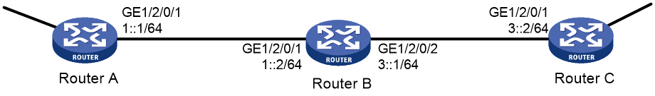
As shown in Figure 6, Router A, Router B, and Router C learn IPv6 routes through RIPng.
Establish an IPsec tunnel between the routers to protect the RIPng packets transmitted in between. Specify the security protocol as ESP, the encryption algorithm as 128-bit AES, and the authentication algorithm as HMAC-SHA1 for the IPsec tunnel.
Analysis
To meet the network configuration requirements, perform the following tasks:
1. Configure basic RIPng.
For more information about RIPng configuration, see Layer 3—IP Routing Configuration Guide.
2. Configure an IPsec profile.
¡ The IPsec profiles on all the routers must have IPsec transform sets that use the same security protocol, authentication and encryption algorithms, and encapsulation mode.
¡ The SPI and key configured for the inbound SA and those for the outbound SA must be the same on each router.
¡ The SPI and key configured for the SAs on all the routers must be the same.
3. Apply the IPsec profile to a RIPng process or to an interface.
Procedure
1. Configure Router A:
# Configure IPv6 addresses for interfaces. (Details not shown.)
# Configure basic RIPng.
<RouterA> system-view
[RouterA] ripng 1
[RouterA-ripng-1] quit
[RouterA] interface gigabitethernet 1/2/0/1
[RouterA-GigabitEthernet1/2/0/1] ripng 1 enable
[RouterA-GigabitEthernet1/2/0/1] quit
# Create and configure the IPsec transform set named tran1.
[RouterA] ipsec transform-set tran1
[RouterA-ipsec-transform-set-tran1] encapsulation-mode transport
[RouterA-ipsec-transform-set-tran1] protocol esp
[RouterA-ipsec-transform-set-tran1] esp encryption-algorithm aes-cbc-128
[RouterA-ipsec-transform-set-tran1] esp authentication-algorithm sha1
[RouterA-ipsec-transform-set-tran1] quit
# Create and configure the IPsec profile named profile001.
[RouterA] ipsec profile profile001 manual
[RouterA-ipsec-profile-manual-profile001] transform-set tran1
[RouterA-ipsec-profile-manual-profile001] sa spi outbound esp 123456
[RouterA-ipsec-profile-manual-profile001] sa spi inbound esp 123456
[RouterA-ipsec-profile-manual-profile001] sa string-key outbound esp simple abcdefg
[RouterA-ipsec-profile-manual-profile001] sa string-key inbound esp simple abcdefg
[RouterA-ipsec-profile-manual-profile001] quit
# Apply the IPsec profile to RIPng process 1.
[RouterA] ripng 1
[RouterA-ripng-1] enable ipsec-profile profile001
[RouterA-ripng-1] quit
2. Configure Router B:
# Configure IPv6 addresses for interfaces. (Details not shown.)
# Configure basic RIPng.
<RouterB> system-view
[RouterB] ripng 1
[RouterB-ripng-1] quit
[RouterB] interface gigabitethernet 1/2/0/1
[RouterB-GigabitEthernet1/2/0/1] ripng 1 enable
[RouterB-GigabitEthernet1/2/0/1] quit
[RouterB] interface gigabitethernet 1/2/0/2
[RouterB-GigabitEthernet1/2/0/2] ripng 1 enable
[RouterB-GigabitEthernet1/2/0/2] quit
# Create and configure the IPsec transform set named tran1.
[RouterB] ipsec transform-set tran1
[RouterB-ipsec-transform-set-tran1] encapsulation-mode transport
[RouterB-ipsec-transform-set-tran1] protocol esp
[RouterB-ipsec-transform-set-tran1] esp encryption-algorithm aes-cbc-128
[RouterB-ipsec-transform-set-tran1] esp authentication-algorithm sha1
[RouterB-ipsec-transform-set-tran1] quit
# Create and configure the IPsec profile named profile001.
[RouterB] ipsec profile profile001 manual
[RouterB-ipsec-profile-manual-profile001] transform-set tran1
[RouterB-ipsec-profile-manual-profile001] sa spi outbound esp 123456
[RouterB-ipsec-profile-manual-profile001] sa spi inbound esp 123456
[RouterB-ipsec-profile-manual-profile001] sa string-key outbound esp simple abcdefg
[RouterB-ipsec-profile-manual-profile001] sa string-key inbound esp simple abcdefg
[RouterB-ipsec-profile-manual-profile001] quit
# Apply the IPsec profile to RIPng process 1.
[RouterB] ripng 1
[RouterB-ripng-1] enable ipsec-profile profile001
[RouterB-ripng-1] quit
3. Configure Router C:
# Configure IPv6 addresses for interfaces. (Details not shown.)
# Configure basic RIPng.
<RouterC> system-view
[RouterC] ripng 1
[RouterC-ripng-1] quit
[RouterC] interface gigabitethernet 1/2/0/1
[RouterC-GigabitEthernet1/2/0/1] ripng 1 enable
[RouterC-GigabitEthernet1/2/0/1] quit
# Create and configure the IPsec transform set named tran1.
[RouterC] ipsec transform-set tran1
[RouterC-ipsec-transform-set-tran1] encapsulation-mode transport
[RouterC-ipsec-transform-set-tran1] protocol esp
[RouterC-ipsec-transform-set-tran1] esp encryption-algorithm aes-cbc-128
[RouterC-ipsec-transform-set-tran1] esp authentication-algorithm sha1
[RouterC-ipsec-transform-set-tran1] quit
# Create and configure the IPsec profile named profile001.
[RouterC] ipsec profile profile001 manual
[RouterC-ipsec-profile-manual-profile001] transform-set tran1
[RouterC-ipsec-profile-manual-profile001] sa spi outbound esp 123456
[RouterC-ipsec-profile-manual-profile001] sa spi inbound esp 123456
[RouterC-ipsec-profile-manual-profile001] sa string-key outbound esp simple abcdefg
[RouterC-ipsec-profile-manual-profile001] sa string-key inbound esp simple abcdefg
[RouterC-ipsec-profile-manual-profile001] quit
# Apply the IPsec profile to RIPng process 1.
[RouterC] ripng 1
[RouterC-ripng-1] enable ipsec-profile profile001
[RouterC-ripng-1] quit
Verifying the configuration
After the configuration is completed, Router A, Router B, and Router C learn IPv6 routing information through RIPng. IPsec SAs are set up successfully on the routers to protect RIPng packets. This example uses Router A to verify the configuration.
# Display the RIPng configuration. The output shows that IPsec profile profile001 has been applied to RIPng process 1.
[RouterA] display ripng 1
RIPng process : 1
Preference : 100
Checkzero : Enabled
Default Cost : 0
Maximum number of load balanced routes : 8
Update time : 30 secs Timeout time : 180 secs
Suppress time : 120 secs Garbage-Collect time : 120 secs
Update output delay: 20(ms) Output count: 3
Graceful-restart interval: 60 secs
Triggered Interval : 5 50 200
Number of periodic updates sent : 186
Number of triggered updates sent : 1
IPsec profile name: profile001
# Display the established IPsec SAs.
[RouterA] display ipsec sa
-------------------------------
Global IPsec SA
-------------------------------
-----------------------------
IPsec profile: profile001
Mode: Manual
-----------------------------
Encapsulation mode: transport
[Inbound ESP SA]
SPI: 123456 (0x3039)
Connection ID: 90194313219
Transform set: ESP-ENCRYPT-AES-CBC-128 ESP-AUTH-SHA1
No duration limit for this SA
[Outbound ESP SA]
SPI: 123456 (0x3039)
Connection ID: 64424509441
Transform set: ESP-ENCRYPT-AES-CBC-128 ESP-AUTH-SHA1
No duration limit for this SA
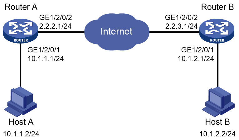
Example: Configuring IPsec tunnel interface-based IPsec for IPv4 packets
As shown in Figure 7, configure IPsec tunnel interface-based IPsec on Router A and Router B to protect the traffic between the subnet of Host A (10.1.1.0/24) and the subnet of Host B (10.1.2.0/24).
Specify the encapsulation mode as tunnel, the security protocol as ESP, the encryption algorithm as 128-bit AES, and the authentication algorithm as HMAC-SHA1. Set up SAs through IKE negotiation.
Procedure
1. Configure Router A:
# Create an IPsec transform set named tran1.
[RouterA] ipsec transform-set tran1
# Configure the packet encapsulation mode as tunnel.
[RouterA-ipsec-transform-set-tran1] encapsulation-mode tunnel
# Configure the security protocol as ESP.
[RouterA-ipsec-transform-set-tran1] protocol esp
# Configure the ESP encryption algorithm as 128-bit AES and authentication algorithm as HMAC-SHA1.
[RouterA-ipsec-transform-set-tran1] esp encryption-algorithm aes-cbc-128
[RouterA-ipsec-transform-set-tran1] esp authentication-algorithm sha1
[RouterA-ipsec-transform-set-tran1] quit
# Create an IKE keychain named keychain1.
[RouterA] ike keychain keychain1
# Specify 123456TESTplat&! in plain text as the pre-shared key to be used with peer 2.2.3.1.
[RouterA-ike-keychain-keychain1] pre-shared-key address 2.2.3.1 255.255.255.0 key simple 123456TESTplat&!
[RouterA-ike-keychain-keychain1] quit
# Create and configure IKE profile profile1.
[RouterA] ike profile profile1
[RouterA-ike-profile-profile1] keychain keychain1
[RouterA-ike-profile-profile1] match remote identity address 2.2.3.1 255.255.255.0
[RouterA-ike-profile-profile1] quit
# Create an IKE-based IPsec profile named map1.
[RouterA] ipsec profile map1 isakmp
# Specify IPsec transform set tran1 for the IPsec profile.
[RouterA-ipsec-profile-isakmp-map1-10] transform-set tran1
# Specify IKE profile profile1 for the IPsec profile.
[RouterA-ipsec-profile-isakmp-map1-10] ike-profile profile1
[RouterA-ipsec-profile-isakmp-map1-10] quit
# Create IPsec tunnel interface Tunnel100, apply IPsec profile map1 to the tunnel interface, and configure the service processing slot for the tunnel interface as slot 3.
[RouterA] interface Tunnel100 mode ipsec
[RouterA-Tunnel100] ip address 3.1.1.1 255.255.255.0
[RouterA-Tunnel100] service chassis 1 slot 3
[RouterA-Tunnel100] source 2.2.2.1
[RouterA-Tunnel100] destination 2.2.3.1
[RouterA-Tunnel100] tunnel protection ipsec profile map1
[RouterA-Tunnel100] quit
# Configure a static route to the subnet of Host B.
[RouterA] ip route-static 10.1.2.0 255.255.255.0 Tunnel100 3.1.1.2
2. Configure Router B:
# Configure IP addresses for interfaces. (Details not shown.)
# Create an IPsec transform set named tran1.
[RouterB] ipsec transform-set tran1
# Configure the packet encapsulation mode as tunnel.
[RouterB-ipsec-transform-set-tran1] encapsulation-mode tunnel
# Configure the security protocol as ESP.
[RouterB-ipsec-transform-set-tran1] protocol esp
# Configure the ESP encryption algorithm as 128-bit AES and authentication algorithm as HMAC-SHA1.
[RouterB-ipsec-transform-set-tran1] esp encryption-algorithm aes-cbc-128
[RouterB-ipsec-transform-set-tran1] esp authentication-algorithm sha1
[RouterB-ipsec-transform-set-tran1] quit
# Configure an IKE keychain named keychain1.
[RouterB] ike keychain keychain1
[RouterB-ike-keychain-keychain1] pre-shared-key address 2.2.2.1 255.255.255.0 key simple 123456TESTplat&!
[RouterB-ike-keychain-keychain1] quit
# Create and configure IKE profile profile1.
[RouterB] ike profile profile1
[RouterB-ike-profile-profile1] keychain keychain1
[RouterB-ike-profile-profile1] match remote identity address 2.2.2.1 255.255.255.0
[RouterB-ike-profile-profile1] quit
# Create an IKE-based IPsec profile named map1.
[RouterB] ipsec profile map1 isakmp
# Specify IPsec transform set tran1 for the IPsec profile.
[RouterB-ipsec-profile-isakmp-map1-10] transform-set tran1
# Specify IKE profile profile1 for the IPsec profile.
[RouterB-ipsec-profile-isakmp-map1-10] ike-profile profile1
[RouterB-ipsec-profile-isakmp-map1-10] quit
# Create IPsec tunnel interface Tunnel100, apply IPsec profile map1 to the tunnel interface, and configure the service processing slot for the tunnel interface as slot 3.
[RouterB] interface Tunnel100 mode ipsec
[RouterB-Tunnel100] ip address 3.1.1.2 255.255.255.0
[RouterB-Tunnel100] service chassis 1 slot 3
[RouterB-Tunnel100] source 2.2.3.1
[RouterB-Tunnel100] destination 2.2.2.1
[RouterB-Tunnel100] tunnel protection ipsec profile map1
[RouterB-Tunnel100] quit
# Configure a static route to the subnet of Host A.
[RouterB] ip route-static 10.1.1.0 255.255.255.0 Tunnel100 3.1.1.1
Verifying the configuration
After the configuration is completed, Router A and Router B will negotiate IPsec SAs through IKE. After the IPsec SAs are successfully negotiated, IPv4 data flows between subnet 10.1.1.0/24 and subnet 10.1.2.0/24 will be protected by the IPsec SAs.
# Display IPsec SAs on Router A.
[RouterA] display ipsec sa
-------------------------------
Interface: Tunnel100
-------------------------------
-----------------------------
IPsec profile:: map1
Mode: ISAKMP
-----------------------------
Tunnel id: 0
Encapsulation mode: tunnel
Perfect Forward Secrecy:
Path MTU: 1443
Tunnel:
local address: 2.2.2.1
remote address: 2.2.3.1
Flow:
sour addr: 0.0.0.0/0.0.0.0 port: 0 protocol: ip
dest addr: 0.0.0.0/0.0.0.0 port: 0 protocol: ip
[Inbound ESP SAs]
SPI: 3769702703 (0xe0b1192f)
Connection ID: 90194313219
Transform set: ESP-ENCRYPT-AES-CBC-128 ESP-AUTH-SHA1
SA duration (kilobytes/sec): 3000/28800
SA remaining duration (kilobytes/sec): 2300/797
Max received sequence-number: 1
Anti-replay check enable: N
Anti-replay window size:
UDP encapsulation used for NAT traversal: N
Status: Active
[Outbound ESP SAs]
SPI: 3840956402 (0xe4f057f2)
Connection ID: 64424509441
Transform set: ESP-ENCRYPT-AES-CBC-128 ESP-AUTH-SHA1
SA duration (kilobytes/sec): 3000/28800
SA remaining duration (kilobytes/sec): 2312/797
Max sent sequence-number: 1
UDP encapsulation used for NAT traversal: N
Status: Active
# Display IPsec SAs on Router B. (Details not shown.)
Configuring IKE
Unless otherwise specified, the term "IKE" in this chapter refers to IKEv1.
About IKE
Built on a framework defined by ISAKMP, Internet Key Exchange (IKE) provides automatic key negotiation and SA establishment services for IPsec.
Benefits of IKE
IKE provides the following benefits for IPsec:
· Automatically negotiates IPsec parameters.
· Performs DH exchanges to calculate shared keys, making sure each SA has a key that is independent of other keys.
· Automatically negotiates SAs when the sequence number in the AH or ESP header overflows, making sure IPsec can provide the anti-replay service by using the sequence number.
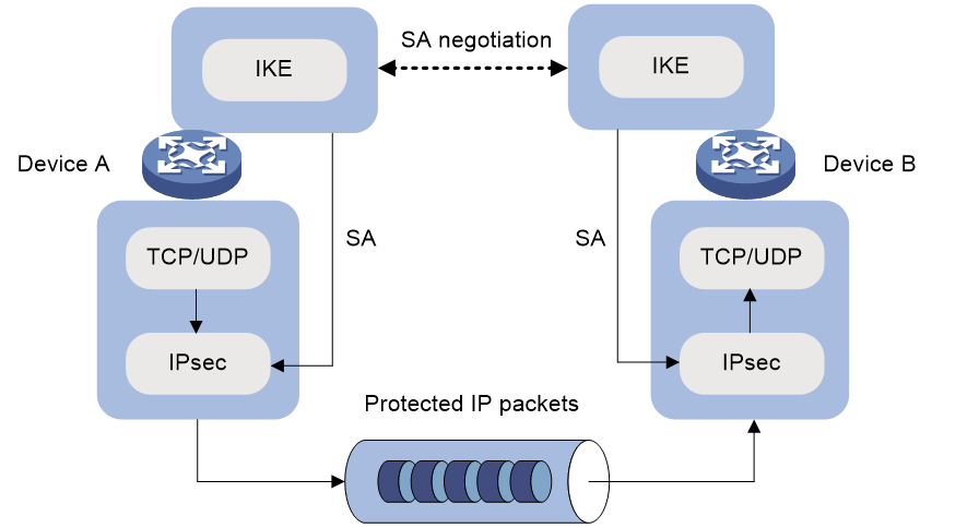
Relationship between IPsec and IKE
As shown in Figure 8, IKE negotiates SAs for IPsec and transfers the SAs to IPsec, and IPsec uses the SAs to protect IP packets.
Figure 8 Relationship between IKE and IPsec
IKE negotiation process
IKE negotiates keys and SAs for IPsec in two phases:
1. Phase 1—The two peers establish an IKE SA, a secure, authenticated channel for communication.
2. Phase 2—Using the IKE SA established in phase 1, the two peers negotiate to establish IPsec SAs.
Phase 1 negotiation can use either main mode or aggressive mode.
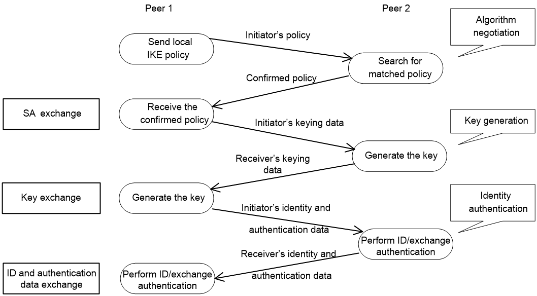
IKE exchange process in main mode
As shown in Figure 9, the main mode of IKE negotiation in phase 1 involves three pairs of messages:
· SA exchange—Used for negotiating the IKE security policy.
· Key exchange—Used for exchanging the DH public value and other values, such as the random number. The two peers use the exchanged data to generate key data and use the encryption key and authentication key to ensure the security of IP packets.
· ID and authentication data exchange—Used for identity authentication.
Figure 9 IKE exchange process in main mode
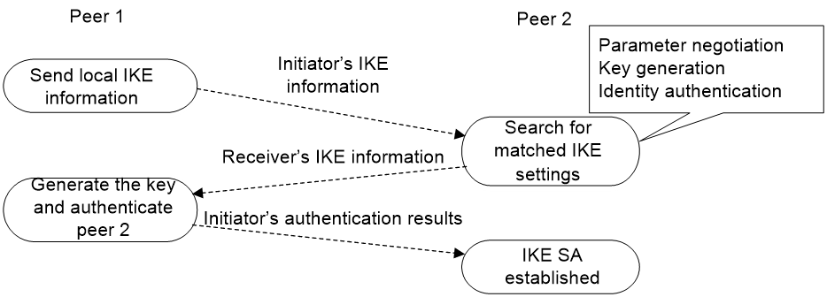
IKE exchange process in aggressive mode
As shown in Figure 10, the process of phase 1 IKE negotiation in aggressive mode is as follows:
1. The initiator (peer 1) sends a message containing the local IKE information to peer 2. The message includes parameters used for IKE SA establishment, keying data, and peer 1's identity information.
2. Peer 2 chooses the IKE establishment parameters to use, generate the key, and authenticate peer 1's identity. Then it sends the IKE data to peer 1.
3. Peer 1 generates the key, authenticates peer 2's identity, and sends the results to peer 1.
After the preceding process, an IKE SA is established between peer 1 and peer 2.
The aggressive mode is faster than the main mode but it does not provide identity information protection. The main mode provides identity information protection but is slower. Choose the appropriate negotiation mode according to your requirements.
Figure 10 IKE exchange process in aggressive mode
IKE security mechanism
IKE has a series of self-protection mechanisms and supports secure identity authentication, key distribution, and IPsec SA establishment on insecure networks.
Identity authentication
The IKE identity authentication mechanism is used to authenticate the identity of the communicating peers. The device supports the following identity authentication methods:
· Pre-shared key authentication—Two communicating peers use the pre-configured shared key for identity authentication.
· RSA signature authentication and DSA signature authentication—Two communicating peers use the digital certificates issued by the CA for identity authentication.
The pre-shared key authentication method does not require certificates and is easy to configure. It is usually deployed in small networks.
The signature authentication methods provide higher security and are usually deployed in networks with the headquarters and some branches. When deployed in a network with many branches, a signature authentication method can simplify the configuration because only one PKI domain is required. If you use the pre-shared key authentication method, you must configure a pre-shared key for each branch on the Headquarters node.
DH algorithm
The DH algorithm is a public key algorithm. With this algorithm, two peers can exchange keying material and then use the material to calculate the shared keys. Due to the decryption complexity, a third party cannot decrypt the keys even after intercepting all keying materials.
PFS
The Perfect Forward Secrecy (PFS) feature is a security feature based on the DH algorithm. After PFS is enabled, an additional DH exchange is performed in IKE phase 2 to make sure IPsec keys have no derivative relations with IKE keys and a broken key brings no threats to other keys.
Protocols and standards
· RFC 2408, Internet Security Association and Key Management Protocol (ISAKMP)
· RFC 2409, The Internet Key Exchange (IKE)
· RFC 2412, The OAKLEY Key Determination Protocol
· Internet Draft, draft-ietf-ipsec-isakmp-xauth-06
· Internet Draft, draft-dukes-ike-mode-cfg-02
IKE tasks at a glance
To configure IKE, perform the following tasks:
1. (Optional.) Configuring an IKE profile
b. Configuring peer IDs for the IKE profile
c. Specifying the IKE keychain or PKI domain
d. Configuring the IKE phase 1 negotiation mode
e. Specifying IKE proposals for the IKE profile
f. Configuring the local ID for the IKE profile
g. Configuring optional features for the IKE profile
2. Configuring an IKE proposal
3. Configuring an IKE keychain
4. (Optional.) Configuring the global identity information
5. (Optional.) Configuring the IKE keepalive feature
6. (Optional.) Configuring the IKE NAT keepalive feature
7. (Optional.) Configuring global IKE DPD
8. (Optional.) Enabling invalid SPI recovery
9. (Optional.) Setting the maximum number of IKE SAs
10. (Optional.) Configuring SNMP notifications for IKE
Prerequisites for IKE configuration
Determine the following parameters prior to IKE configuration:
· The algorithms to be used during IKE negotiation, including the identity authentication method, encryption algorithm, authentication algorithm, and DH group.
¡ Different algorithms provide different levels of protection. A stronger algorithm provides more resistance to decryption but uses more resources.
¡ A DH group that uses more bits provides higher security but needs more time for processing.
· The pre-shared key or PKI domain for IKE negotiation. For more information about PKI, see "Configuring PKI."
· The IKE-based IPsec profiles for the communicating peers. If you do not specify an IKE profile in an IPsec profile, the device selects an IKE profile for the IPsec profile. If no IKE profile is configured, the globally configured IKE settings are used. For more information about IPsec, see "Configuring IPsec."
Configuring an IKE profile
Creating an IKE profile
About this task
Perform this task to create an IKE profile.
An IKE profile is intended to provide a set of parameters for IKE negotiation.
Procedure
1. Enter system view.
system-view
2. Create an IKE profile and enter its view.
ike profile profile-name
Configuring peer IDs for the IKE profile
About this task
Perform this task to configure the peer IDs for IKE profile matching. When the device needs to select an IKE profile for IKE negotiation with a peer, it compares the received peer ID with the peer IDs of its local IKE profiles. If a match is found, it uses the IKE profile with the matching peer ID for IKE negotiation.
Restrictions and guidelines
For an IKE profile, you can configure multiple peer IDs. A peer ID configured earlier has a higher priority.
Two IKE peers must both have or both not have peer IDs configured.
Procedure
1. Enter system view.
system-view
2. Enter IKE profile view.
ike profile profile-name
3. Configure a peer ID for the IKE profile.
match remote { certificate policy-name | identity { address { { ipv4-address [ mask | mask-length ] | range low-ipv4-address high-ipv4-address } | ipv6 { ipv6-address [ prefix-length ] | range low-ipv6-address high-ipv6-address } } [ vpn-instance vpn-instance-name ] | fqdn fqdn-name | user-fqdn user-fqdn-name } }
Specifying the IKE keychain or PKI domain
Restrictions and guidelines
Configure the IKE keychain or PKI domain for the IKE proposals to use. To use digital signature authentication, configure a PKI domain. To use pre-shared key authentication, configure an IKE keychain.
Procedure
1. Enter system view.
system-view
2. Enter IKE profile view.
ike profile profile-name
3. Specify the keychain for pre-shared key authentication or the PKI domain used to request a certificate for digital signature authentication.
¡ Specify the keychain.
keychain keychain-name
¡ Specify the PKI domain.
certificate domain domain-name
By default, no IKE keychain or PKI domain is specified in an IKE profile.
Configuring the IKE phase 1 negotiation mode
Restrictions and guidelines
Specify the IKE phase 1 negotiation mode (main or aggressive) that the device uses as the initiator. When the device acts as the responder, it uses the IKE negotiation mode of the initiator.
Procedure
1. Enter system view.
system-view
2. Enter IKE profile view.
ike profile profile-name
3. Specify the IKE negotiation mode for phase 1.
exchange-mode { aggressive | main }
By default, IKE negotiation in phase 1 uses the main mode.
Specifying IKE proposals for the IKE profile
Restrictions and guidelines
Specify the IKE proposals that the device can use as the initiator. An IKE proposal specified earlier has a higher priority. When the device acts as the responder, it uses the IKE proposals configured in system view to match the IKE proposals received from the initiator. If no matching proposal is found, the negotiation fails.
Procedure
1. Enter system view.
system-view
2. Enter IKE profile view.
ike profile profile-name
3. Specify IKE proposals for the IKE profile.
proposal proposal-number&<1-6>
By default, no IKE proposals are specified for an IKE profile and the IKE proposals configured in system view are used for IKE negotiation.
Configuring the local ID for the IKE profile
Restrictions and guidelines
For digital signature authentication, the device can use an ID of any type. If the local ID is an IP address that is different from the IP address in the local certificate, the device uses the FQDN (the device name configured by using the sysname command) instead.
For pre-shared key authentication, the device can use an ID of any type other than the DN.
Procedure
1. Enter system view.
system-view
2. Enter IKE profile view.
ike profile profile-name
3. Configure the local ID.
local-identity { address { ipv4-address | ipv6 ipv6-address } | dn | fqdn [ fqdn-name ] | user-fqdn [ user-fqdn-name ] }
By default, no local ID is configured for an IKE profile, and an IKE profile uses the local ID configured in system view. If the local ID is not configured in system view, the IKE profile uses the IP address of the interface to which the IPsec profile is applied as the local ID.
Configuring optional features for the IKE profile
1. Enter system view.
system-view
2. Enter IKE profile view.
ike profile profile-name
3. Configure optional features as needed.
¡ Configure IKE DPD.
dpd interval interval [ retry seconds ] { on-demand | periodic }
By default, IKE DPD is not configured for an IKE profile and an IKE profile uses the DPD settings configured in system view. If IKE DPD is not configured in system view either, the device does not perform dead IKE peer detection.
The IKE DPD settings configured in the IKE profile view take precedence over those configured in system view.
¡ Specify the local interface or IP address to which the IKE profile can be applied.
match local address { interface-type interface-number | { ipv4-address | ipv6 ipv6-address } [ vpn-instance vpn-instance-name ] }
By default, an IKE profile can be applied to any local interface or IP address.
An IKE profile configured with this command has a higher priority over those not configured with this command.
¡ Specify a priority for the IKE profile.
priority priority
By default, the priority of an IKE profile is 100.
The device selects a local IKE profile for IKE negotiation as follows:
- First, it selects an IKE profile with the match local address command configured.
- If a tie exists, it selects the IKE profile with a smaller priority number.
- If a tie still exists, it selects the IKE profile configured earlier.
Configuring an IKE proposal
About this task
An IKE proposal defines a set of attributes describing how IKE negotiation in phase 1 should take place. You can create multiple IKE proposals with different priorities. The priority of an IKE proposal is represented by its sequence number. The lower the sequence number, the higher the priority.
Two peers must have at least one matching IKE proposal for successful IKE negotiation. During IKE negotiation:
· The initiator sends its IKE proposals to the peer.
¡ If the initiator is using an IPsec profile with an IKE profile, the initiator sends all IKE proposals specified in the IKE profile to the peer. An IKE proposal specified earlier for the IKE profile has a higher priority.
¡ If the initiator is using an IPsec profile with no IKE profile, the initiator sends all its IKE proposals to the peer. An IKE proposal with a smaller number has a higher priority.
· The peer searches its own IKE proposals for a match. The search starts from the IKE proposal with the highest priority and proceeds in descending order of priority until a match is found. The matching IKE proposals are used to establish the IKE SA. If all user-defined IKE proposals are found mismatching, the two peers use their default IKE proposals to establish the IKE SA.
Two matching IKE proposals have the same encryption algorithm, authentication method, authentication algorithm, and DH group. The SA lifetime takes the smaller one of the two proposals' SA lifetime settings.
Procedure
1. Enter system view.
system-view
2. Create an IKE proposal and enter its view.
ike proposal proposal-number
By default, a default IKE proposal exists.
3. Configure a description for the IKE proposal.
description
By default, an IKE proposal does not have a description.
4. Specify an encryption algorithm for the IKE proposal.
encryption-algorithm { 3des-cbc | aes-cbc-128 | aes-cbc-192 | aes-cbc-256 | des-cbc | sm4-cbc }
By default, the 56-bit DES encryption algorithm in CBC mode is used .
5. Specify an authentication method for the IKE proposal.
authentication-method { dsa-signature | pre-share | rsa-de | rsa-signature | sm2-de }
By default, the pre-shared key authentication method is used.
6. Specify an authentication algorithm for the IKE proposal.
authentication-algorithm { md5 | sha | sha256 | sha384 | sha512 | sm3 }
By default, the HMAC-SHA1 authentication algorithm is used.
7. Specify a DH group for key negotiation in phase 1.
dh { group1 | group14 | group2 | group24 | group5 }
DH group 1 (the 768-bit DH group) is used by default.
8. (Optional.) Set the IKE SA lifetime for the IKE proposal.
sa duration seconds
By default, the IKE SA lifetime is 86400 seconds.
Configuring an IKE keychain
About this task
Perform this task when you configure the IKE to use the pre-shared key for authentication.
Follow these guidelines when you configure an IKE keychain:
· Two peers must be configured with the same pre-shared key to pass pre-shared key authentication.
· You can specify the local address configured in IPsec profile view (using the local-address command) for the IKE keychain to be applied. If no local address is configured, specify the IP address of the interface that uses the IPsec profile.
· The device determines the priority of an IKE keychain as follows:
a. The device examines the existence of the match local address command. An IKE keychain with the match local address command configured has a higher priority.
b. If a tie exists, the device compares the priority numbers. An IKE keychain with a smaller priority number has a higher priority.
c. If a tie still exists, the device prefers an IKE keychain configured earlier.
Procedure
1. Enter system view.
system-view
2. Create an IKE keychain and enter its view.
ike keychain keychain-name [ vpn-instance vpn-instance-name ]
3. Configure a pre-shared key.
pre-shared-key { address { ipv4-address [ mask | mask-length ] | ipv6 ipv6-address [ prefix-length ] } | hostname host-name } key { cipher | simple } string
By default, no pre-shared key is configured.
4. (Optional.) Specify a local interface or IP address to which the IKE keychain can be applied.
match local address { interface-type interface-number | { ipv4-address | ipv6 ipv6-address } [ vpn-instance vpn-instance-name ] }
By default, an IKE keychain can be applied to any local interface or IP address.
5. (Optional.) Specify a priority for the IKE keychain.
priority priority
The default priority is 100.
Configuring the global identity information
Restrictions and guidelines
The global identity can be used by the device for all IKE SA negotiations, and the local identity (set by the local-identity command) can be used only by the device that uses the IKE profile.
When signature authentication is used, you can set any type of the identity information.
When pre-shared key authentication is used, you cannot set the DN as the identity.
Procedure
1. Enter system view.
system-view
2. Configure the global identity to be used by the local end.
ike identity { address { ipv4-address | ipv6 ipv6-address } | dn | fqdn [ fqdn-name ] | user-fqdn [ user-fqdn-name ] }
By default, the IP address of the interface to which the IPsec profile is applied is used as the IKE identity.
3. (Optional.) Configure the local device to always obtain the identity information from the local certificate for signature authentication.
ike signature-identity from-certificate
By default, the local end uses the identity information specified by local-identity or ike identity for signature authentication.
Configure this command when the aggressive mode and signature authentication are used and the device interconnects with a Comware 5-based peer device. Comware 5 supports only DN for signature authentication.
Configuring the IKE keepalive feature
About this task
IKE sends keepalive packets to query the liveness of the peer. If the peer is configured with the keepalive timeout time, you must configure the keepalive interval on the local device. If the peer receives no keepalive packets during the timeout time, the IKE SA is deleted along with the IPsec SAs it negotiated.
Restrictions and guidelines
Configure IKE DPD instead of IKE keepalive unless IKE DPD is not supported on the peer. The IKE keepalive feature sends keepalives at regular intervals, which consumes network bandwidth and resources.
The keepalive timeout time configured on the local device must be longer than the keepalive interval configured at the peer. Since it seldom occurs that more than three consecutive packets are lost on a network, you can set the keepalive timeout three times as long as the keepalive interval.
Procedure
1. Enter system view.
system-view
2. Set the IKE SA keepalive interval.
ike keepalive interval interval
By default, no keepalives are sent to the peer.
3. Set the IKE SA keepalive timeout time.
ike keepalive timeout seconds
By default, IKE SA keepalive never times out.
Configuring the IKE NAT keepalive feature
About this task
If IPsec traffic passes through a NAT device, you must configure the NAT traversal feature. If no packet travels across an IPsec tunnel in a period of time, the NAT sessions are aged and deleted, disabling the tunnel from transmitting data to the intended end. To prevent NAT sessions from being aged, configure the NAT keepalive feature on the IKE gateway behind the NAT device to send NAT keepalive packets to its peer periodically to keep the NAT session alive.
Procedure
1. Enter system view.
system-view
2. Set the IKE NAT keepalive interval.
ike nat-keepalive seconds
The default interval is 20 seconds.
Configuring global IKE DPD
About this task
DPD detects dead peers. It can operate in periodic mode or on-demand mode.
· Periodic DPD—Sends a DPD message at regular intervals. It features an earlier detection of dead peers, but consumes more bandwidth and CPU.
· On-demand DPD—Sends a DPD message based on traffic. When the device has traffic to send and is not aware of the liveness of the peer, it sends a DPD message to query the status of the peer. If the device has no traffic to send, it never sends DPD messages. As a best practice, use the on-demand mode.
The IKE DPD works as follows:
1. The local device sends a DPD message to the peer, and waits for a response from the peer.
2. If the peer does not respond within the retry interval specified by the retry seconds parameter, the local device resends the message.
3. If still no response is received within the retry interval, the local end sends the DPD message again. The system allows a maximum of two retries.
4. If the local device receives no response after two retries, the device considers the peer to be dead, and deletes the IKE SA along with the IPsec SAs it negotiated.
5. If the local device receives a response from the peer during the detection process, the peer is considered alive. The local device performs a DPD detection again when the triggering interval is reached or it has traffic to send, depending on the DPD mode.
Restrictions and guidelines
When DPD settings are configured in both IKE profile view and system view, the DPD settings in IKE profile view apply. If DPD is not configured in IKE profile view, the DPD settings in system view apply.
It is a good practice to set the triggering interval longer than the retry interval so that a DPD detection is not triggered during a DPD retry.
Procedure
1. Enter system view.
system-view
2. Enable sending IKE DPD messages.
ike dpd interval interval [ retry seconds ] { on-demand | periodic }
By default, IKE DPD is disabled.
Enabling invalid SPI recovery
About this task
An IPsec "black hole" occurs when one IPsec peer fails (for example, a peer can fail if a reboot occurs). One peer fails and loses its SAs with the other peer. When an IPsec peer receives a data packet for which it cannot find an SA, an invalid SPI is encountered. The peer drops the data packet and tries to send an SPI invalid notification to the data originator. This notification is sent by using the IKE SA. Because no IKE SA is available, the notification is not sent. The originating peer continues sending the data by using the IPsec SA that has the invalid SPI, and the receiving peer keeps dropping the traffic.
The invalid SPI recovery feature enables the receiving peer to set up an IKE SA with the originator so that an SPI invalid notification can be sent. Upon receiving the notification, the originating peer deletes the IPsec SA that has the invalid SPI. If the originator has data to send, new SAs will be set up.
Restrictions and guidelines
Use caution when you enable the invalid SPI recovery feature because using this feature can result in a DoS attack. Attackers can make a great number of invalid SPI notifications to the same peer.
Procedure
1. Enter system view.
system-view
2. Enable invalid SPI recovery.
ike invalid-spi-recovery enable
By default, the invalid SPI recovery is disabled.
Setting the maximum number of IKE SAs
About this task
You can set the maximum number of half-open IKE SAs and the maximum number of established IKE SAs.
· The supported maximum number of half-open IKE SAs depends on the device's processing capability. Adjust the maximum number of half-open IKE SAs to make full use of the device's processing capability without affecting the IKE SA negotiation efficiency.
· The supported maximum number of established IKE SAs depends on the device's memory space. Adjust the maximum number of established IKE SAs to make full use of the device's memory space without affecting other applications in the system.
Procedure
1. Enter system view.
system-view
2. Set the maximum number of half-open IKE SAs and the maximum number of established IKE SAs.
ike limit { max-negotiating-sa negotiation-limit | max-sa sa-limit }
By default, the maximum number of half-open IKE SAs and IPsec SAs is 200, and the number of established IKE SAs is not limited.
Configuring SNMP notifications for IKE
About this task
After you enable SNMP notifications for IKE, the IKE module notifies the NMS of important module events. The notifications are sent to the device's SNMP module. For the notifications to be sent correctly, you must also configure SNMP on the device. For more information about SNMP notifications, see Network Management and Monitoring Configuration Guide.
To generate and output SNMP notifications for a specific IKE failure or event type, perform the following tasks:
1. Enable SNMP notifications for IKE globally.
2. Enable SNMP notifications for the failure or event type.
Procedure
1. Enter system view
system-view
2. Enable SNMP notifications for IKE globally.
snmp-agent trap enable ike global
By default, SNMP notifications for IKE are enabled.
3. Enable SNMP notifications for the specified failure or event types.
snmp-agent trap enable ike [ attr-not-support | auth-failure | cert-type-unsupport | cert-unavailable | decrypt-failure | encrypt-failure | invalid-cert-auth | invalid-cookie | invalid-id | invalid-proposal | invalid-protocol | invalid-sign | no-sa-failure | proposal-add | proposal–delete | tunnel-start | tunnel-stop | unsupport-exch-type ] *
By default, SNMP notifications for all failure and event types are enabled.
Display and maintenance commands for IKE
Execute display commands in any view and reset commands in user view.
|
Task |
Command |
|
Display configuration information about all IKE proposals. |
display ike proposal |
|
Display information about the current IKE SAs. |
display ike sa [ verbose [ connection-id connection-id [ vpn-instance vpn-instance-name ] ] ] |
|
Display IKE statistics. |
display ike statistics |
|
Delete IKE SAs. |
reset ike sa [ connection-id connection-id ] |
|
Clear IKE MIB statistics. |
reset ike statistics |
Troubleshooting IKE
IKE negotiation failed because no matching IKE proposals were found
Symptom
1. The IKE SA is in Unknown state.
<Sysname> display ike sa
Connection-ID Remote Flag DOI
------------------------------------------------------------------
1 192.168.222.5 Unknown IPsec
Flags:
RD--READY RL--REPLACED FD-FADING RK-REKEY
2. When IKE event debugging and packet debugging are enabled, the following messages appear:
IKE event debugging message:
The attributes are unacceptable.
IKE packet debugging message:
Construct notification packet: NO_PROPOSAL_CHOSEN.
Analysis
Certain IKE proposal settings are incorrect.
Solution
1. Examine the IKE proposal configuration to see whether the two ends have matching IKE proposals.
2. Modify the IKE proposal configuration to make sure the two ends have matching IKE proposals.
IKE negotiation failed because no IKE proposals or IKE keychains are specified correctly
Symptom
1. The IKE SA is in Unknown state.
<Sysname> display ike sa
Connection-ID Remote Flag DOI
------------------------------------------------------------------
1 192.168.222.5 Unknown IPsec
Flags:
RD--READY RL--REPLACED FD-FADING RK-REKEY
2. The following IKE event debugging or packet debugging message appeared:
IKE event debugging message:
Notification PAYLOAD_MALFORMED is received.
IKE packet debugging message:
Construct notification packet: PAYLOAD_MALFORMED.
Analysis
· If the following debugging information appeared, the matched IKE profile is not using the matched IKE proposal:
Failed to find proposal 1 in profile profile1.
· If the following debugging information appeared, the matched IKE profile is not using the matched IKE keychain:
Failed to find keychain keychain1 in profile profile1.
Solution
· Verify that the matched IKE proposal (IKE proposal 1 in this debugging message example) is specified for the IKE profile (IKE profile 1 in the example).
· Verify that the matched IKE keychain (IKE keychain 1 in this debugging message example) is specified for the IKE profile (IKE profile 1 in the example).
