- Table of Contents
- Related Documents
-
| Title | Size | Download |
|---|---|---|
| 06-Spanning tree configuration | 336.58 KB |
Contents
Spanning tree protocol overview
Calculation process of the STP algorithm
The configuration BPDU forwarding mechanism of STP
Configuring spanning tree protocols
Restrictions and guidelines: spanning tree protocol configuration
Spanning tree protocol tasks at a glance
Setting the spanning tree mode
Enabling the spanning tree feature
Display and maintenance commands for the spanning tree protocols
Spanning tree protocol overview
Spanning tree protocols eliminate loops in a physical link-redundant network by selectively blocking redundant links and putting them in a standby state.
The recent versions of STP include the Rapid Spanning Tree Protocol (RSTP) and the Multiple Spanning Tree Protocol (MSTP).
About STP
STP was developed based on the 802.1d standard of IEEE to eliminate loops at the data link layer in a LAN. Networks often have redundant links as backups in case of failures, but loops are a very serious problem. Devices running STP detect loops in the network by exchanging information with one another. They eliminate loops by selectively blocking certain ports to prune the loop structure into a loop-free tree structure. This avoids proliferation and infinite cycling of packets that would occur in a loop network.
In a narrow sense, STP refers to IEEE 802.1d STP. In a broad sense, STP refers to the IEEE 802.1d STP and various enhanced spanning tree protocols derived from that protocol.
STP protocol frames
STP uses bridge protocol data units (BPDUs), also known as configuration messages, as its protocol frames. This chapter uses BPDUs to represent all types of spanning tree protocol frames.
STP-enabled devices exchange BPDUs to establish a spanning tree. BPDUs contain sufficient information for the devices to complete spanning tree calculation.
STP uses two types of BPDUs, configuration BPDUs and topology change notification (TCN) BPDUs.
Configuration BPDUs
Devices exchange configuration BPDUs to elect the root bridge and determine port roles. Figure 1 shows the configuration BPDU format.
Figure 1 Configuration BPDU format
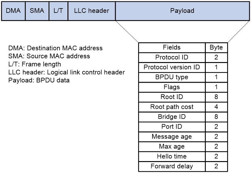
The payload of a configuration BPDU includes the following fields:
· Protocol ID—Fixed at 0x0000, which represents IEEE 802.1d.
· Protocol version ID—Spanning tree protocol version ID. The protocol version ID for STP is 0x00.
· BPDU type—Type of the BPDU. The value is 0x00 for a configuration BPDU.
· Flags—An 8-bit field indicates the purpose of the BPDU. The lowest bit is the Topology Change (TC) flag. The highest bit is the Topology Change Acknowledge (TCA) flag. All other bits are reserved.
· Root ID—Root bridge ID formed by the priority and MAC address of the root bridge.
· Root path cost—Cost of the path to the root bridge.
· Bridge ID—Designated bridge ID formed by the priority and MAC address of the designated bridge.
· Port ID—Designated port ID formed by the priority and global port number of the designated port.
· Message age—Age of the configuration BPDU while it propagates in the network.
· Max age—Maximum age of the configuration BPDU stored on the switch.
· Hello time—Configuration BPDU transmission interval.
· Forward delay—Delay for STP bridges to transit port state.
Devices use the root bridge ID, root path cost, designated bridge ID, designated port ID, message age, max age, hello time, and forward delay for spanning tree calculation.
TCN BPDUs
Devices use TCN BPDUs to announce changes in the network topology. Figure 2 shows the TCN BPDU format.
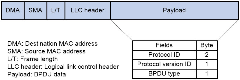
The payload of a TCN BPDU includes the following fields:
· Protocol ID—Fixed at 0x0000, which represents IEEE 802.1d.
· Protocol version ID—Spanning tree protocol version ID. The protocol version ID for STP is 0x00.
· BPDU type—Type of the BPDU. The value is 0x80 for a TCN BPDU.
A non-root bridge sends TCN BPDUs when one of the following events occurs on the bridge:
· A port transits to the forwarding state, and the bridge has a minimum of one designated port.
· A port transits from the forwarding or learning state to the blocking state.
The non-root bridge uses TCN BPDUs to notify the root bridge once the network topology changes. The root bridge then sets the TC flag in its configuration BPDU and propagates it to other bridges.
Basic concepts in STP
Root bridge
A tree network must have a root bridge. The entire network contains only one root bridge, and all the other bridges in the network are called leaf nodes. The root bridge is not permanent, but can change with changes of the network topology.
Upon initialization of a network, each device generates and periodically sends configuration BPDUs, with itself as the root bridge. After network convergence, only the root bridge generates and periodically sends configuration BPDUs. The other devices only forward the BPDUs.
Root port
Designated bridge and designated port
|
Classification |
Designated bridge |
Designated port |
|
For a device |
Device directly connected to the local device and responsible for forwarding BPDUs to the local device. |
Port through which the designated bridge forwards BPDUs to this device. |
|
For a LAN |
Device responsible for forwarding BPDUs to this LAN segment. |
Port through which the designated bridge forwards BPDUs to this LAN segment. |
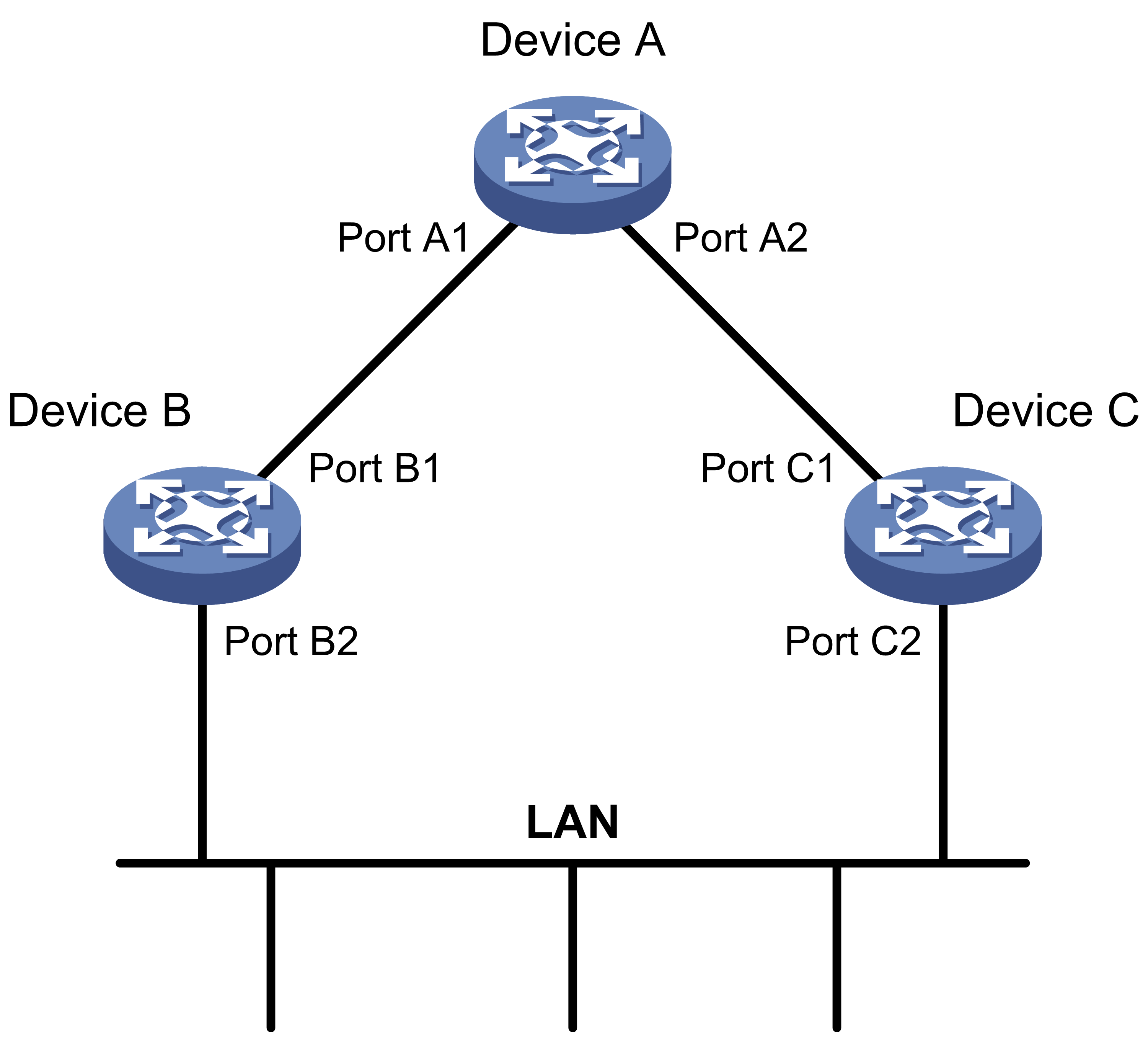
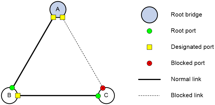
As shown in Figure 3, Device B and Device C are directly connected to a LAN.
If Device A forwards BPDUs to Device B through port A1, the designated bridge and designated port are as follows:
· The designated bridge for Device B is Device A.
· The designated port for Device B is port A1 on Device A.
If Device B forwards BPDUs to the LAN, the designated bridge and designated port are as follows:
· The designated bridge for the LAN is Device B.
· The designated port for the LAN is port B2 on Device B.
Figure 3 Designated bridges and designated ports
Port states
Table 1 lists the port states in STP.
|
State |
Receives/sends BPDUs |
Learns MAC addresses |
Forwards user data |
|
Disabled |
No |
No |
No |
|
Listening |
Yes |
No |
No |
|
Learning |
Yes |
Yes |
No |
|
Forwarding |
Yes |
Yes |
Yes |
|
Blocking |
Receive |
No |
No |
Path cost
Path cost is a reference value used for link selection in STP. To prune the network into a loop-free tree, STP calculates path costs to select the most robust links and block redundant links that are less robust.
Calculation process of the STP algorithm
In STP calculation, a device compares the priorities of the received configuration BPDUs from different ports, and elects the root bridge, root ports and designated ports. When the spanning tree calculation is completed, a tree-shape topology forms.
The spanning tree calculation process described in the following sections is an example of a simplified process.
Network initialization
Upon initialization of a device, each port generates a BPDU with the following contents:
· The port as the designated port.
· The device as the root bridge.
· 0 as the root path cost.
· The device ID as the designated bridge ID.
Root bridge selection
The root bridge can be selected in the following methods:
· Automatic election—Initially, each STP-enabled device on the network assumes itself to be the root bridge, with its own device ID as the root bridge ID. By exchanging configuration BPDUs, the devices compare their root bridge IDs to elect the device with the smallest root bridge ID as the root bridge.
· Manual assignment—You can configure a device as the root bridge or a secondary root bridge of a spanning tree.
¡ A spanning tree can have only one root bridge. If you configure multiple devices as the root bridge for a spanning tree, the device with the lowest MAC address is selected.
¡ You can configure one or multiple secondary root bridges for a spanning tree. When the root bridge fails or is shut down, a secondary root bridge can take over. If multiple secondary root bridges are configured, the one with the lowest MAC address is selected. However, if a new root bridge is configured, the secondary root bridge is not selected.
Root port and designated ports selection on the non-root bridges
|
Step |
Description |
|
1 |
A non-root-bridge device regards the port on which it received the optimum configuration BPDU as the root port. Table 2 describes how the optimum configuration BPDU is selected. |
|
2 |
Based on the configuration BPDU and the path cost of the root port, the device calculates a designated port configuration BPDU for each of the other ports. · The root bridge ID is replaced with that of the configuration BPDU of the root port. · The root path cost is replaced with that of the configuration BPDU of the root port plus the path cost of the root port. · The designated bridge ID is replaced with the ID of this device. · The designated port ID is replaced with the ID of this port. |
|
3 |
The device compares the calculated configuration BPDU with the configuration BPDU on the port whose port role will be determined. Then, the device acts depending on the result of the comparison: · If the calculated configuration BPDU is superior, the device performs the following operations: ¡ Considers this port as the designated port. ¡ Replaces the configuration BPDU on the port with the calculated configuration BPDU. ¡ Periodically sends the calculated configuration BPDU. · If the configuration BPDU on the port is superior, the device blocks this port without updating its configuration BPDU. The blocked port can receive BPDUs, but cannot send BPDUs or forward data traffic. |
When the network topology is stable, only the root port and designated ports forward user traffic. Other ports are all in the blocking state to receive BPDUs but not to forward BPDUs or user traffic.
Table 2 Selecting the optimum configuration BPDU
|
Step |
Actions |
|
1 |
Upon receiving a configuration BPDU on a port, the device compares the priority of the received configuration BPDU with that of the configuration BPDU generated by the port. · If the former priority is lower, the device discards the received configuration BPDU and keeps the configuration BPDU the port generated. · If the former priority is higher, the device replaces the content of the configuration BPDU generated by the port with the content of the received configuration BPDU. |
|
2 |
The device compares the configuration BPDUs of all the ports and chooses the optimum configuration BPDU. |
The following are the principles of configuration BPDU comparison:
1. The configuration BPDU with the lowest root bridge ID has the highest priority.
2. If configuration BPDUs have the same root bridge ID, their root path costs are compared. For example, the root path cost in a configuration BPDU plus the path cost of a receiving port is S. The configuration BPDU with the smallest S value has the highest priority.
3. If all configuration BPDUs have the same root bridge ID and S value, the following attributes are compared in sequence:
a. Designated bridge IDs.
b. Designated port IDs.
c. IDs of the receiving ports.
The configuration BPDU that contains a smaller designated bridge ID, designated port ID, or receiving port ID is selected.
A tree-shape topology forms when the root bridge, root ports, and designated ports are selected.
Example of STP calculation
Figure 4 provides an example showing how the STP algorithm works.
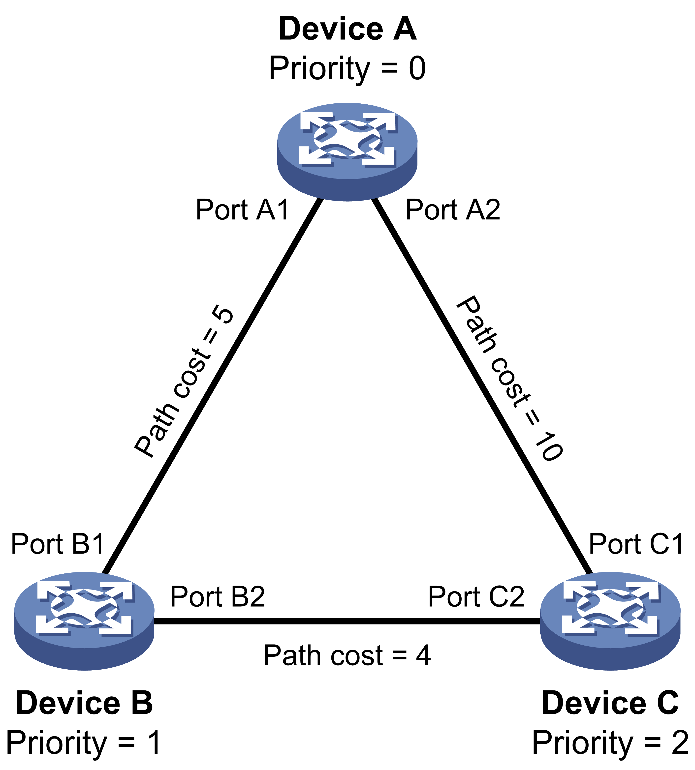
As shown in Figure 4, the priority values of Device A, Device B, and Device C are 0, 1, and 2, respectively. The path costs of links among the three devices are 5, 10, and 4.
Device state initialization
In Table 3, each configuration BPDU contains the following fields: root bridge ID, root path cost, designated bridge ID, and designated port ID.
Table 3 Initial state of each device
|
Device |
Port name |
Configuration BPDU on the port |
|
Device A |
Port A1 |
{0, 0, 0, Port A1} |
|
Port A2 |
{0, 0, 0, Port A2} |
|
|
Device B |
Port B1 |
{1, 0, 1, Port B1} |
|
Port B2 |
{1, 0, 1, Port B2} |
|
|
Device C |
Port C1 |
{2, 0, 2, Port C1} |
|
Port C2 |
{2, 0, 2, Port C2} |
Configuration BPDUs comparison on each device
In Table 4, each configuration BPDU contains the following fields: root bridge ID, root path cost, designated bridge ID, and designated port ID.
Table 4 Comparison process and result on each device
|
Device |
Comparison process |
Configuration BPDU on ports after comparison |
|
Device A |
Port A1 performs the following operations: 1. Receives the configuration BPDU of Port B1 {1, 0, 1, Port B1}. 2. Determines that its existing configuration BPDU {0, 0, 0, Port A1} is superior to the received configuration BPDU. 3. Discards the received one. Port A2 performs the following operations: 1. Receives the configuration BPDU of Port C1 {2, 0, 2, Port C1}. 2. Determines that its existing configuration BPDU {0, 0, 0, Port A2} is superior to the received configuration BPDU. 3. Discards the received one. Device A determines that it is both the root bridge and designated bridge in the configuration BPDUs of all its ports. It considers itself as the root bridge. It does not change the configuration BPDU of any port and starts to periodically send configuration BPDUs. |
· Port A1: {0, 0, 0, Port A1} · Port A2: {0, 0, 0, Port A2} |
|
Device B |
Port B1 performs the following operations: 4. Receives the configuration BPDU of Port A1 {0, 0, 0, Port A1}. 5. Determines that the received configuration BPDU is superior to its existing configuration BPDU {1, 0, 1, Port B1}. 6. Updates its configuration BPDU. Port B2 performs the following operations: 1. Receives the configuration BPDU of Port C2 {2, 0, 2, Port C2}. 2. Determines that its existing configuration BPDU {1, 0, 1, Port B2} is superior to the received configuration BPDU. 3. Discards the received BPDU. |
· Port B1: {0, 0, 0, Port A1} · Port B2: {1, 0, 1, Port B2} |
|
Device B performs the following operations: 1. Compares the configuration BPDUs of all its ports. 2. Decides that the configuration BPDU of Port B1 is the optimum. 3. Selects Port B1 as the root port with the configuration BPDU unchanged. Based on the configuration BPDU and path cost of the root port, Device B calculates a designated port configuration BPDU for Port B2 {0, 5, 1, Port B2}. Device B compares it with the existing configuration BPDU of Port B2 {1, 0, 1, Port B2}. Device B determines that the calculated one is superior, and determines that Port B2 is the designated port. It replaces the configuration BPDU on Port B2 with the calculated one, and periodically sends the calculated configuration BPDU. |
· Root port (Port B1): {0, 0, 0, Port A1} · Designated port (Port B2): {0, 5, 1, Port B2} |
|
|
Device C |
Port C1 performs the following operations: 1. Receives the configuration BPDU of Port A2 {0, 0, 0, Port A2}. 2. Determines that the received configuration BPDU is superior to its existing configuration BPDU {2, 0, 2, Port C1}. 3. Updates its configuration BPDU. Port C2 performs the following operations: 1. Receives the original configuration BPDU of Port B2 {1, 0, 1, Port B2}. 2. Determines that the received configuration BPDU is superior to the existing configuration BPDU {2, 0, 2, Port C2}. 3. Updates its configuration BPDU. |
· Port C1: {0, 0, 0, Port A2} · Port C2: {1, 0, 1, Port B2} |
|
Device C performs the following operations: 1. Compares the configuration BPDUs of all its ports. 2. Decides that the configuration BPDU of Port C1 is the optimum. 3. Selects Port C1 as the root port with the configuration BPDU unchanged. Based on the configuration BPDU and path cost of the root port, Device C calculates the configuration BPDU of Port C2 {0, 10, 2, Port C2}. Device C compares it with the existing configuration BPDU of Port C2 {1, 0, 1, Port B2}. Device C determines that the calculated configuration BPDU is superior to the existing one, selects Port C2 as the designated port, and replaces the configuration BPDU of Port C2 with the calculated one. |
· Root port (Port C1): {0, 0, 0, Port A2} · Designated port (Port C2): {0, 10, 2, Port C2} |
|
|
Port C2 performs the following operations: 1. Receives the updated configuration BPDU of Port B2 {0, 5, 1, Port B2}. 2. Determines that the received configuration BPDU is superior to its existing configuration BPDU {0, 10, 2, Port C2}. 3. Updates its configuration BPDU. Port C1 performs the following operations: 1. Receives a periodic configuration BPDU {0, 0, 0, Port A2} from Port A2. 2. Determines that it is the same as the existing configuration BPDU. 3. Discards the received BPDU. |
· Port C1: {0, 0, 0, Port A2} · Port C2: {0, 5, 1, Port B2} |
|
|
Device C determines that the root path cost of Port C1 is larger than that of Port C2. The root path cost of Port C1 is 10, root path cost of the received configuration BPDU (0) plus path cost of Port C1 (10). The root path cost of Port C2 is 9, root path cost of the received configuration BPDU (5) plus path cost of Port C2 (4). Device C determines that the configuration BPDU of Port C2 is the optimum, and selects Port C2 as the root port with the configuration BPDU unchanged. Based on the configuration BPDU and path cost of the root port, Device C performs the following operations: 1. Calculates a designated port configuration BPDU for Port C1 {0, 9, 2, Port C1}. 2. Compares it with the existing configuration BPDU of Port C1 {0, 0, 0, Port A2}. 3. Determines that the existing configuration BPDU is superior to the calculated one and blocks Port C1 with the configuration BPDU unchanged. Port C1 does not forward data until a new event triggers a spanning tree calculation process: for example, the link between Device B and Device C is down. |
· Blocked port (Port C1): {0, 0, 0, Port A2} · Root port (Port C2): {0, 5, 1, Port B2} |
Final calculated spanning tree
After the comparison processes described in Table 4, a spanning tree with Device A as the root bridge is established, as shown in Figure 5.
Figure 5 The final calculated spanning tree
The configuration BPDU forwarding mechanism of STP
The configuration BPDUs of STP are forwarded according to these guidelines:
· Upon network initiation, every device regards itself as the root bridge and generates configuration BPDUs with itself as the root. Then it sends the configuration BPDUs at a regular hello interval.
· If the root port receives a configuration BPDU superior to the configuration BPDU of the port, the device performs the following operations:
¡ Increases the message age carried in the configuration BPDU.
¡ Starts a timer to time the configuration BPDU.
¡ Sends this configuration BPDU through the designated port.
· If a designated port receives a configuration BPDU with a lower priority than its configuration BPDU, the port immediately responds with its configuration BPDU.
· If a path fails, the root port on this path no longer receives new configuration BPDUs and the old configuration BPDUs will be discarded due to timeout. The device generates a configuration BPDU with itself as the root and sends the BPDUs and TCN BPDUs. This triggers a new spanning tree calculation process to establish a new path to restore the network connectivity.
However, the newly calculated configuration BPDU cannot be propagated throughout the network immediately. As a result, the old root ports and designated ports that have not detected the topology change continue forwarding data along the old path. If the new root ports and designated ports begin to forward data as soon as they are elected, a temporary loop might occur.
STP timers
The most important timing parameters in STP calculation are forward delay, hello time, and max age.
· Forward delay
Forward delay is the delay time for port state transition. By default, the forward delay is 15 seconds.
A path failure can cause spanning tree re-calculation to adapt the spanning tree structure to the change. However, the resulting new configuration BPDU cannot propagate throughout the network immediately. If the newly elected root ports and designated ports start to forward data immediately, a temporary loop will likely occur.
The newly elected root ports or designated ports must go through the listening and learning states before they transit to the forwarding state. This requires twice the forward delay time and allows the new configuration BPDU to propagate throughout the network.
· Hello time
The device sends configuration BPDUs at the hello time interval to the neighboring devices to ensure that the paths are fault-free. By default, the hello time is 2 seconds. If the device does not receive configuration BPDUs within the timeout period, it recalculates the spanning tree. The formula for calculating the timeout period is timeout period = timeout factor × 3 × hello time.
· Max age
The device uses the max age to determine whether a stored configuration BPDU has expired and discards it if the max age is exceeded. By default, the max age is 20 seconds. In the CIST of an MSTP network, the device uses the max age timer to determine whether a configuration BPDU received by a port has expired. If it is expired, a new spanning tree calculation process starts. The max age timer does not take effect on MSTIs.
If a port does not receive any configuration BPDUs within the timeout period, the port transits to the listening state. The device will recalculate the spanning tree. It takes the port 50 seconds to transit back to the forwarding state. This period includes 20 seconds for the max age, 15 seconds for the listening state, and 15 seconds for the learning state.
To ensure a fast topology convergence, make sure the timer settings meet the following formulas:
· 2 × (forward delay – 1 second) ≥ max age
· Max age ≥ 2 × (hello time + 1 second)
About RSTP
RSTP achieves rapid network convergence by allowing a newly elected root port or designated port to enter the forwarding state much faster than STP.
RSTP protocol frames
An RSTP BPDU uses the same format as an STP BPDU except that a Version1 length field is added to the payload of RSTP BPDUs. The differences between an RSTP BPDU and an STP BPDU are as follows:
· Protocol version ID—The value is 0x02 for RSTP.
· BPDU type—The value is 0x02 for RSTP BPDUs.
· Flags—All 8 bits are used.
· Version1 length—The value is 0x00, which means no version 1 protocol information is present.
RSTP does not use TCN BPDUs to advertise topology changes. RSTP floods BPDUs with the TC flag set in the network to advertise topology changes.
Basic concepts in RSTP
Port roles
In addition to root port and designated port, RSTP also uses the following port roles:
· Alternate port—Acts as the backup port for a root port. When the root port is blocked, the alternate port takes over.
· Backup port—Acts as the backup port of a designated port. When the designated port is invalid, the backup port becomes the new designated port. A loop occurs when two ports of the same spanning tree device are connected, so the device blocks one of the ports. The blocked port is the backup port.
· Edge port—Directly connects to a user host rather than a network device or network segment.
Port states
RSTP uses the discarding state to replace the disabled, blocking, and listening states in STP. Table 5 shows the differences between the port states in RSTP and STP.
Table 5 Port state differences between RSTP and STP
|
STP port state |
RSTP port state |
Sends BPDU |
Learns MAC addresses |
Forwards user data |
|
Disabled |
Discarding |
No |
No |
No |
|
Blocking |
Discarding |
No |
No |
No |
|
Listening |
Discarding |
Yes |
No |
No |
|
Learning |
Learning |
Yes |
Yes |
No |
|
Forwarding |
Forwarding |
Yes |
Yes |
Yes |
How RSTP works
During RSTP calculation, the following events occur:
· If a port in discarding state becomes an alternate port, it retains its state.
· If a port in discarding state is elected as the root port or designated port, it enters the learning state after the forward delay. The port learns MAC addresses, and enters the forwarding state after another forward delay.
¡ A newly elected RSTP root port rapidly enters the forwarding state if the following requirements are met:
- The old root port on the device has stopped forwarding data.
- The upstream designated port has started forwarding data.
¡ A newly elected RSTP designated port rapidly enters the forwarding state if one of the following requirements is met:
- The designated port is configured as an edge port which directly connects to a user terminal.
- The designated port connects to a point-to-point link and receives a handshake response from the directly connected device.
RSTP BPDU processing
In RSTP, a non-root bridge actively sends RSTP BPDUs at the hello time through designated ports without waiting for the root bridge to send RSTP BPDUs. This enables RSTP to quickly detect link failures. If a device fails to receive any RSTP BPDUs on a port within triple the hello time, the device considers that a link failure has occurred. After the stored configuration BPDU expires, the device floods RSTP BPDUs with the TC flag set to initiate a new RSTP calculation.
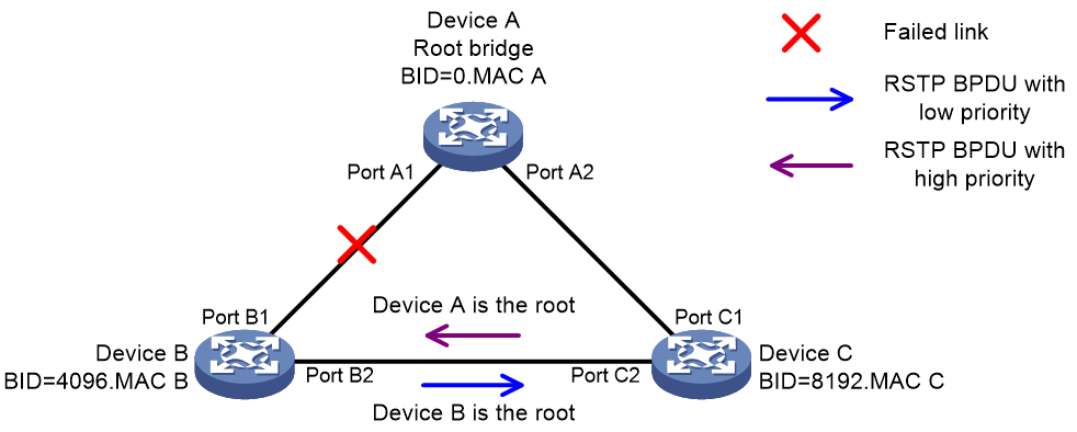
In RSTP, a port in blocking state can immediately respond to an RSTP BPDU with a lower priority than its own BPDU.
As shown in Figure 6, Device A is the root bridge. The priority of Device B is higher than the priority of Device C. Port C2 on Device C is blocked.
When the link between Device A and Device B fails, the following events occur:
1. Device B sends an RSTP BPDU with itself as the root bridge to Device C.
2. Device C compares the RSTP BPDU with its own BPDU.
3. Because the RSTP BPDU from Device B has a lower priority, Device C sends its own BPDU to Device B.
4. Device B considers that Port B2 is the root port and stops sending RSTP BPDUs to Device C.
Figure 6 BPDU processing in RSTP
About MSTP
MSTP features
Developed based on IEEE 802.1s, MSTP overcomes the limitations of STP and RSTP. In addition to supporting rapid network convergence, it allows data flows of different VLANs to be forwarded along separate paths. This provides a better load sharing mechanism for redundant links.
MSTP provides the following features:
· MSTP divides a switched network into multiple regions, each of which contains multiple spanning trees that are independent of one another.
· MSTP supports mapping VLANs to spanning tree instances by means of a VLAN-to-instance mapping table. MSTP can reduce communication overheads and resource usage by mapping multiple VLANs to one instance.
· MSTP prunes a loop network into a loop-free tree, which avoids proliferation and endless cycling of frames in a loop network. In addition, it supports load balancing of VLAN data by providing multiple redundant paths for data forwarding.
· MSTP is compatible with STP and RSTP.
MSTP protocol frames
Figure 7 shows the format of an MSTP BPDU.
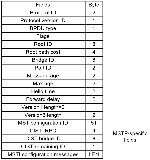
The first 13 fields of an MSTP BPDU are the same as an RSTP BPDU. The other six fields are unique to MSTP.
· Protocol version ID—The value is 0x03 for MSTP.
· BPDU type—The value is 0x02 for RSTP/MSTP BPDUs.
· Root ID—ID of the common root bridge.
· Root path cost—CIST external path cost.
· Bridge ID—ID of the regional root for the IST or an MSTI.
· Port ID—ID of the designated port in the CIST.
· Version3 length—Length of the MSTP-specific fields. Devices use this field for verification upon receiving an MSTP BPDU.
· MST configuration ID—Includes the format selector, configuration name, revision level, and configuration digest. The value for format selector is fixed at 0x00. The other parameters are used to identify the MST region for the originating bridge.
· CIST IRPC—Internal root path cost (IRPC) from the originating bridge to the root of the MST region.
· CIST bridge ID—ID of the bridge that sends the MSTP BPDU.
· CIST remaining ID—Remaining hop count. This field limits the scale of the MST region. The regional root sends a BPDU with the remaining hop count set to the maximum value. Each device that receives the BPDU decrements the hop count by one. When the hop count reaches zero, the BPDU is discarded. Devices beyond the maximum hops of the MST region cannot participate in spanning tree calculation. The default remaining hop count is 20.
· MSTI configuration messages—Contains MSTI configuration messages. Each MSTI configuration message is 16 bytes. This field can contain 0 to 64 MSTI configuration messages. The number of the MSTI configuration messages is determined by the number of MSTIs in the MST region.
Basic concepts in MSTP
Figure 8 shows a switched network that contains four MST regions, each MST region containing four MSTP devices. Figure 9 shows the networking topology of MST region 3.
Figure 8 Basic concepts in MSTP
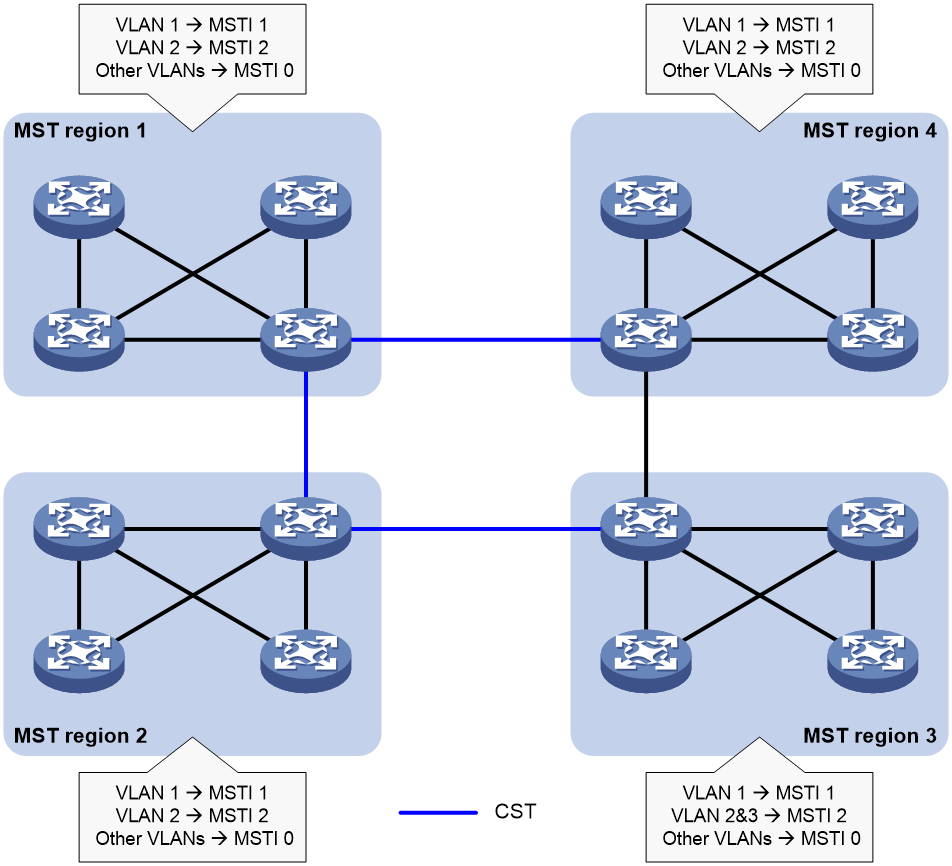
Figure 9 Network diagram and topology of MST region 3
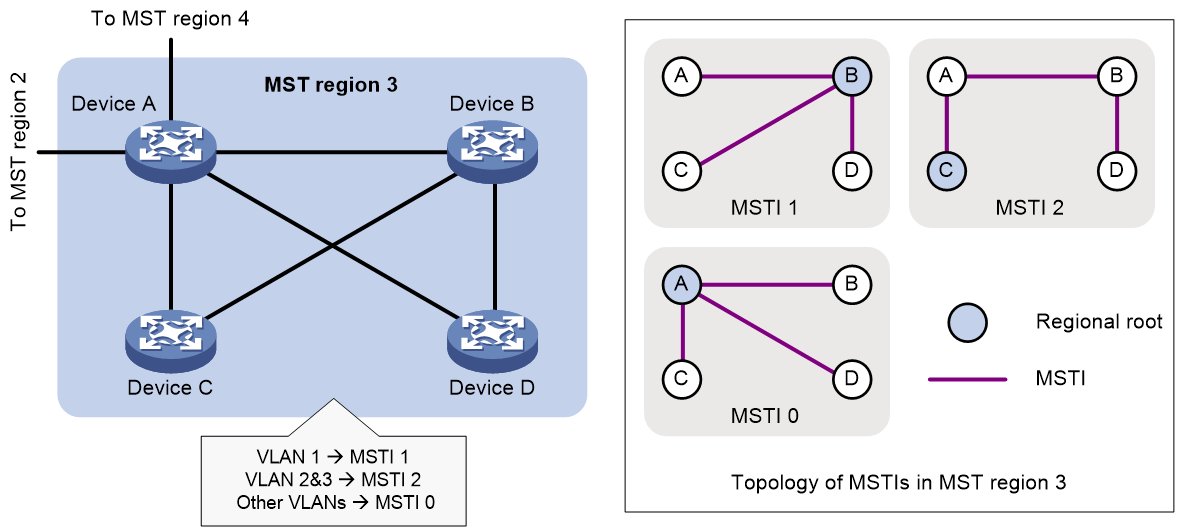
MST region
A multiple spanning tree region (MST region) consists of multiple devices in a switched network and the network segments among them. All these devices have the following characteristics:
· A spanning tree protocol enabled
· Same region name
· Same VLAN-to-instance mapping configuration
· Same MSTP revision level
· Physically linked together
Multiple MST regions can exist in a switched network. You can assign multiple devices to the same MST region, as shown in Figure 8.
· The switched network contains four MST regions, MST region 1 through MST region 4.
· All devices in each MST region have the same MST region configuration.
MSTI
MSTP can generate multiple independent spanning trees in an MST region, and each spanning tree is mapped to the specific VLANs. Each spanning tree is referred to as a multiple spanning tree instance (MSTI).
In Figure 9, MST region 3 contains three MSTIs, MSTI 1, MSTI 2, and MSTI 0.
VLAN-to-instance mapping table
As an attribute of an MST region, the VLAN-to-instance mapping table describes the mapping relationships between VLANs and MSTIs.
In Figure 9, the VLAN-to-instance mapping table of MST region 3 is as follows:
· VLAN 1 to MSTI 1.
· VLAN 2 and VLAN 3 to MSTI 2.
· Other VLANs to MSTI 0.
MSTP achieves load balancing by means of the VLAN-to-instance mapping table.
CST
The common spanning tree (CST) is a single spanning tree that connects all MST regions in a switched network. If you regard each MST region as a device, the CST is a spanning tree calculated by these devices through STP or RSTP.
The blue lines in Figure 8 represent the CST.
IST
An internal spanning tree (IST) is a spanning tree that runs in an MST region. It is also called MSTI 0, a special MSTI to which all VLANs are mapped by default.
In Figure 8, MSTI 0 is the IST in MST region 3.
CIST
The common and internal spanning tree (CIST) is a single spanning tree that connects all devices in a switched network. It consists of the ISTs in all MST regions and the CST.
In Figure 8, the ISTs (MSTI 0) in all MST regions plus the inter-region CST constitute the CIST of the entire network.
Regional root
The root bridge of the IST or an MSTI within an MST region is the regional root of the IST or MSTI. Based on the topology, different spanning trees in an MST region might have different regional roots, as shown in MST region 3 in Figure 9.
· The regional root of MSTI 1 is Device B.
· The regional root of MSTI 2 is Device C.
· The regional root of MSTI 0 (also known as the IST) is Device A.
Common root bridge
The common root bridge is the root bridge of the CIST.
In Figure 8, the common root bridge is a device in MST region 1.
Port roles
A port can play different roles in different MSTIs. As shown in Figure 10, an MST region contains Device A, Device B, Device C, and Device D. Port A1 and port A2 of Device A connect to the common root bridge. Port B2 and Port B3 of Device B form a loop. Port C3 and Port C4 of Device C connect to other MST regions. Port D3 of Device D directly connects to a host.
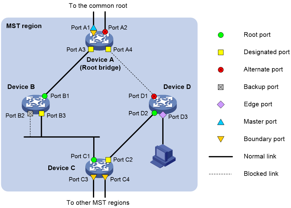
MSTP calculation involves the following port roles:
· Root port—Forwards data for a non-root bridge to the root bridge. The root bridge does not have any root port.
· Designated port—Forwards data to the downstream network segment or device.
· Alternate port—Acts as the backup port for a root port or master port. When the root port or master port is blocked, the alternate port takes over.
· Backup port—Acts as the backup port of a designated port. When the designated port is invalid, the backup port becomes the new designated port. A loop occurs when two ports of the same spanning tree device are connected, so the device blocks one of the ports. The blocked port acts as the backup.
· Edge port—Directly connects to a user host rather than a network device or network segment.
· Master port—Acts as a port on the shortest path from the local MST region to the common root bridge. The master port is not always located on the regional root. It is a root port on the IST or CIST and still a master port on the other MSTIs.
· Boundary port—Connects an MST region to another MST region or to an STP/RSTP-running device. In MSTP calculation, a boundary port's role on an MSTI is consistent with its role on the CIST. However, that is not true with master ports. A master port on MSTIs is a root port on the CIST.
Port states
In MSTP, a port can be in one of the following states:
· Forwarding—The port receives and sends BPDUs, learns MAC addresses, and forwards user traffic.
· Learning—The port receives and sends BPDUs, learns MAC addresses, but does not forward user traffic. Learning is an intermediate port state.
· Discarding—The port receives and sends BPDUs, but does not learn MAC addresses or forward user traffic.
|
|
NOTE: When in different MSTIs, a port can be in different states. |
A port state is not exclusively associated with a port role. Table 6 lists the port states that each port role supports. (A check mark [√] indicates that the port supports this state, while a dash [—] indicates that the port does not support this state.)
Table 6 Port states that different port roles support
|
Port role (right) Port state (below) |
Root port/master port |
Designated port |
Alternate port |
Backup port |
|
Forwarding |
√ |
√ |
— |
— |
|
Learning |
√ |
√ |
— |
— |
|
Discarding |
√ |
√ |
√ |
√ |
How MSTP works
MSTP divides an entire Layer 2 network into multiple MST regions, which are connected by a calculated CST. Inside an MST region, multiple spanning trees, called MSTIs, are calculated. Among these MSTIs, MSTI 0 is the IST.
Like STP, MSTP uses configuration BPDUs to calculate spanning trees. An important difference is that an MSTP BPDU carries the MSTP configuration of the bridge from which the BPDU is sent.
CIST calculation
During the CIST calculation, the following process takes place:
· The device with the highest priority is elected as the root bridge of the CIST.
· MSTP generates an IST within each MST region through calculation.
· MSTP regards each MST region as a single device and generates a CST among these MST regions through calculation.
The CST and ISTs constitute the CIST of the entire network.
MSTI calculation
Within an MST region, MSTP generates different MSTIs for different VLANs based on the VLAN-to-instance mappings. For each spanning tree, MSTP performs a separate calculation process similar to spanning tree calculation in STP. For more information, see "Calculation process of the STP algorithm."
In MSTP, a VLAN frame is forwarded along the following paths:
· Within an MST region, the frame is forwarded along the corresponding MSTI.
· Between two MST regions, the frame is forwarded along the CST.
Protocols and standards
MSTP is documented in the following protocols and standards:
· IEEE 802.1d, Media Access Control (MAC) Bridges
· IEEE 802.1w, Part 3: Media Access Control (MAC) Bridges—Amendment 2: Rapid Reconfiguration
· IEEE 802.1s, Virtual Bridged Local Area Networks—Amendment 3: Multiple Spanning Trees
· IEEE 802.1Q-REV/D1.3, Media Access Control (MAC) Bridges and Virtual Bridged Local Area Networks —Clause 13: Spanning tree Protocols
Configuring spanning tree protocols
Restrictions and guidelines: spanning tree protocol configuration
· Some spanning tree features are supported in Layer 2 Ethernet interface view and Layer 2 aggregate interface view. Unless otherwise stated, these views are collectively referred to as interface view in this document. BPDU drop can be configured only in Layer 2 Ethernet interface view.
· Configurations made in system view take effect globally. Configurations made in Layer 2 Ethernet interface view take effect only on the interface. Configurations made in Layer 2 aggregate interface view take effect only on the aggregate interface. Configurations made on an aggregation member port can take effect only after the port is removed from the aggregation group.
· After you enable a spanning tree protocol on a Layer 2 aggregate interface, the system performs spanning tree calculation on the Layer 2 aggregate interface. It does not perform spanning tree calculation on the aggregation member ports. The spanning tree protocol enable state and forwarding state of each selected member port are consistent with those of the corresponding Layer 2 aggregate interface.
· The member ports of an aggregation group do not participate in spanning tree calculation. However, the ports still reserve their spanning tree configurations for participating in spanning tree calculation after leaving the aggregation group.
Spanning tree protocol tasks at a glance
STP tasks at a glance
Configuring the root bridge
To configure the root bridge in STP mode, perform the following tasks:
1. Setting the spanning tree mode
Set the spanning tree mode to STP.
2. Enabling the spanning tree feature
Configuring the leaf nodes
To configure the leaf nodes in STP mode, perform the following tasks:
1. Setting the spanning tree mode
Set the spanning tree mode to STP
2. Enabling the spanning tree feature
RSTP tasks at a glance
Configuring the root bridge
To configure the root bridge in RSTP mode, perform the following tasks:
1. Setting the spanning tree mode
Set the spanning tree mode to RSTP.
2. Enabling the spanning tree feature
Configuring the leaf nodes
To configure the leaf nodes in RSTP mode, perform the following tasks:
1. Setting the spanning tree mode
Set the spanning tree mode to RSTP.
2. Enabling the spanning tree feature
MSTP tasks at a glance
Configuring the root bridge
To configure the root bridge in MSTP mode, perform the following tasks:
1. Setting the spanning tree mode
Set the spanning tree mode to MSTP.
2. Configuring an MST region
3. Enabling the spanning tree feature
Configuring the leaf nodes
To configure the leaf nodes in MSTP mode, perform the following tasks:
1. Setting the spanning tree mode
Set the spanning tree mode to MSTP.
2. Configuring an MST region
3. Enabling the spanning tree feature
Setting the spanning tree mode
About this task
The spanning tree modes include:
· STP mode—All ports of the device send STP BPDUs. Select this mode when the peer device of a port supports only STP.
· RSTP mode—All ports of the device send RSTP BPDUs. A port in this mode automatically transits to the STP mode when it receives STP BPDUs from the peer device. A port in this mode does not transit to the MSTP mode when it receives MSTP BPDUs from the peer device.
· MSTP mode—All ports of the device send MSTP BPDUs. A port in this mode automatically transits to the STP mode when receiving STP BPDUs from the peer device. A port in this mode does not transit to the RSTP mode when receiving RSTP BPDUs from the peer device.
Restrictions and guidelines
The MSTP mode is compatible with the RSTP mode, and the RSTP mode is compatible with the STP mode.
Procedure
1. Enter system view.
system-view
2. Set the spanning tree mode.
stp mode { mstp | rstp | stp }
The default setting is the MSTP mode.
Configuring an MST region
About this task
Spanning tree devices belong to the same MST region if they are both connected through a physical link and configured with the following details:
· Format selector (0 by default, not configurable).
· MST region name.
· MST region revision level.
· VLAN-to-instance mapping entries in the MST region.
The configuration of MST region-related parameters (especially the VLAN-to-instance mapping table) might cause MSTP to begin a new spanning tree calculation. To reduce the possibility of topology instability, the MST region configuration takes effect only after you activate it by doing one of the following:
· Use the active region-configuration command.
· Enable a spanning tree protocol by using the stp global enable command if the spanning tree protocol is disabled.
Restrictions and guidelines
In STP or RSTP mode, MST region configurations do not take effect.
Procedure
1. Enter system view.
system-view
2. Enter MST region view.
stp region-configuration
3. Configure the MST region name.
region-name name
The default setting is the MAC address.
4. Configure the VLAN-to-instance mapping table. Choose one option as needed:
¡ Map a list of VLANs to an MSTI.
instance instance-id vlan vlan-id-list
¡ Quickly create a VLAN-to-instance mapping table.
vlan-mapping modulo modulo
By default, all VLANs in an MST region are mapped to the CIST (or MSTI 0).
5. Configure the MSTP revision level of the MST region.
revision-level level
The default setting is 0.
6. (Optional.) Display the MST region configurations that are not activated yet.
check region-configuration
7. Manually activate MST region configuration.
active region-configuration
Enabling the spanning tree feature
Restrictions and guidelines
You must enable the spanning tree feature for the device before any other spanning tree related configurations can take effect. In STP, RSTP, or MSTP mode, make sure the spanning tree feature is enabled globally and on the desired ports.
To exclude specific ports from spanning tree calculation and save CPU resources, disable the spanning tree feature for these ports with the undo stp enable command. Make sure no loops occur in the network after you disable the spanning tree feature on these ports.
Procedure
1. Enter system view.
system-view
2. Enable the spanning tree feature.
stp global enable
The default setting varies by device model.
3. Enter interface view.
interface interface-type interface-number
4. Enable the spanning tree feature for the port.
stp enable
By default, the spanning tree feature is enabled on all ports.
Display and maintenance commands for the spanning tree protocols
Execute display commands in any view and reset command in user view.
|
Task |
Command |
|
Display BPDU statistics on ports. |
display stp bpdu-statistics [ interface interface-type interface-number [ instance instance-list ] ] |
|
Display the port role calculation history for the specified MSTI or all MSTIs. |
display stp [ instance instance-list ] history [ chassis chassis-number slot slot-number ] |
|
Display the incoming and outgoing TC/TCN BPDU statistics by all ports in the specified MSTI or all MSTIs. |
display stp [ instance instance-list ] tc [ chassis chassis-number slot slot-number ] |
|
Display the spanning tree status and statistics. |
display stp [ instance instance-list ] [ interface interface-list | chassis chassis-number slot slot-number ] [ brief ] |
|
Display the MST region configuration information that has taken effect. |
display stp region-configuration |
|
Display the root bridge information of all MSTIs. |
display stp root |
|
Clear the spanning tree statistics. |
reset stp [ interface interface-list ] |
