- Table of Contents
- Related Documents
-
| Title | Size | Download |
|---|---|---|
| 02-Hardware Information and Specifications | 5.04 MB |
1 Product models and technical specifications
3 Removable components and compatibility matrixes
Removable components and their compatibility with the device
10/100/1000BASE-T autosensing Ethernet port
10/100/1000BASE-T autosensing Ethernet port LED
Input status LED and output status LED on the power supply
Port status LED on the expansion module
1 Product models and technical specifications
Product models
This document is applicable to the S5560S-EI switch series and the S5130S-HI switch series. Table1-1 describes models of the S5560S-EI switch series and the S5130S-HI switch series.
|
Switch model |
Product code |
|
|
S5560S-EI switch series |
S5560S-28F-EI |
LS-S5560S-28F-EI LS-S5560S-28F-EI-GL |
|
S5560S-52F-EI |
LS-S5560S-52F-EI LS-S5560S-52F-EI-GL |
|
|
S5560S-28P-EI |
LS-S5560S-28P-EI LS-S5560S-28P-EI-GL |
|
|
S5560S-52P-EI |
LS-S5560S-52P-EI LS-S5560S-52P-EI-GL |
|
|
S5560S-28S-EI |
LS-S5560S-28S-EI LS-S5560S-28S-EI-GL |
|
|
S5560S-52S-EI |
LS-S5560S-52S-EI LS-S5560S-52S-EI-GL |
|
|
S5560S-28S-PWR-EI |
LS-S5560S-28S-PWR-EI LS-S5560S-28S-PWR-EI-GL |
|
|
S5560S-52S-PWR-EI |
LS-S5560S-52S-PWR-EI LS-S5560S-52S-PWR-EI-GL |
|
|
S5130S-HI switch series |
S5130S-28S-HI |
LS-S5130S-28S-HI LS-S5130S-28S-HI-GL |
|
S5130S-52S-HI |
LS-S5130S-52S-HI LS-S5130S-52S-HI-GL |
|
|
S5130S-28C-HI |
LS-S5130S-28C-HI LS-S5130S-28C-HI-GL |
|
|
S5130S-52C-HI |
LS-S5130S-52C-HI LS-S5130S-52C-HI-GL |
|
|
S5130S-28S-PWR-HI |
LS-5130S-28S-PWR-EI LS-5130S-28S-PWR-EI-GL |
|
|
S5130S-28S-UPWR-HI |
LS-5130S-28S-UPWR-HI |
|
|
S5130S-52S-PWR-HI |
LS-5130S-52S-PWR-EI LS-5130S-52S-PWR-EI-GL |
|
|
S5130S-28C-PWR-HI |
LS-5130S-28C-PWR-EI LS-5130S-28C-PWR-EI-GL |
|
|
S5130S-52C-PWR-HI |
LS-5130S-52C-PWR-EI LS-5130S-52C-PWR-EI-GL |
|
Technical specifications
S5560S-EI series
Table1-2 Technical specifications for non-PoE switches of the S5560S-EI series (1)
|
Item |
S5560S-28P-EI |
S5560S-52P-EI |
S5560S-28S-EI |
S5560S-52S-EI |
|
Dimensions (H × W × D) |
43.6 × 440 × 360 mm (1.72 × 17.32 × 14.17 in) |
|||
|
Weight |
≤ 8 kg (17.64 lb) |
≤ 8.5 kg (18.74 lb) |
≤ 8 kg (17.64 lb) |
≤ 8.5 kg (18.74 lb) |
|
Console port |
· 1 × Micro USB console port · 1 × serial console port Only the Micro USB console port is available when you connect both ports. |
|||
|
USB port |
1 |
1 |
1 |
1 |
|
Management Ethernet port |
1 |
1 |
1 |
1 |
|
10/100/1000BASE-T autosensing Ethernet port |
24 (The rightmost eight ports and their corresponding SFP ports form combo interfaces.) |
48 |
24 (The rightmost eight ports and their corresponding SFP ports form combo interfaces.) |
48 |
|
SFP port |
12 (The leftmost eight ports and their corresponding 10/100/1000BASE-T autosensing Ethernet ports form combo interfaces.) |
4 |
8 (Each and its corresponding 10/100/1000BASE-T autosensing Ethernet port form a combo interface.) |
N/A |
|
SFP+ port |
N/A |
N/A |
4 |
4 |
|
Power supply slot |
2, on the rear panel |
|||
|
Input voltage |
PSR75-12A: · Rated voltage: ¡ 100 VAC to 240 VAC @ 50 or 60 Hz ¡ 240 VDC · Max voltage: ¡ 90 VAC to 290 VAC @ 47 to 63 Hz ¡ 180 VDC to 320 VDC PSR150-A1: · Rated voltage: 100 VAC to 240 VAC @ 50 or 60 Hz · Max voltage: 90 VAC to 264 VAC @ 47 to 63 Hz PSR150-D1: · Rated voltage: –48 VDC to –60 VDC · Max voltage: –36 VDC to –72 VDC DC power source for the PSR150-D1 power supply: –48 VDC power source in the equipment room or an RPS (H3C RPS800-A or RPS1600-A) |
|||
|
Minimum power consumption |
· Single PSR75-12A input: 12 W · Single PSR150-A1 input: 15 W · Single PSR150-D1 input: 15 W · Dual PSR75-12A inputs: 13 W · Dual PSR150-A1 inputs: 20 W · Dual PSR150-D1 inputs: 21 W |
· Single PSR75-12A input: 21 W · Single PSR150-A1 input: 24 W · Single PSR150-D1 input: 25 W · Dual PSR75-12A inputs: 23 W · Dual PSR150-A1 inputs: 29 W · Dual PSR150-D1 inputs: 30 W |
· Single PSR75-12A input: 12 W · Single PSR150-A1 input: 16 W · Single PSR150-D1 input: 15 W · Dual PSR75-12A inputs: 14 W · Dual PSR150-A1 inputs: 22 W · Dual PSR150-D1 inputs: 21 W |
· Single PSR75-12A input: 21 W · Single PSR150-A1 input: 25 W · Single PSR150-D1 input: 26 W · Dual PSR75-12A inputs: 24 W · Dual PSR150-A1 inputs: 30 W · Dual PSR150-D1 inputs: 32 W |
|
Maximum power consumption |
· Single PSR75-12A input: 29 W · Single PSR150-A1 input: 32 W · Single PSR150-D1 input: 35 W · Dual PSR75-12A inputs: 32 W · Dual PSR150-A1 inputs: 39 W · Dual PSR150-D1 inputs: 44 W |
· Single PSR75-12A input: 44 W · Single PSR150-A1 input: 46 W · Single PSR150-D1 input: 57 W · Dual PSR75-12A inputs: 46 W · Dual PSR150-A1 inputs: 52 W · Dual PSR150-D1 inputs: 59 W |
· Single PSR75-12A input: 33 W · Single PSR150-A1 input: 35 W · Single PSR150-D1 input: 40 W · Dual PSR75-12A inputs: 36 W · Dual PSR150-A1 inputs: 42 W · Dual PSR150-D1 inputs: 47 W |
· Single PSR75-12A input: 47 W · Single PSR150-A1 input: 49 W · Single PSR150-D1 input: 58 W · Dual PSR75-12A inputs: 49 W · Dual PSR150-A1 inputs: 56 W · Dual PSR150-D1 inputs: 60 W |
|
Chassis leakage current compliance |
UL 62368-1/EN 62368-1/IEC 62368-1/UL 60950-1/EN 60950-1/IEC 60950-1/GB4943.1 |
|||
|
Melting current of power supply fuse |
· PSR75-12A: 3.15 A, 250 V · PSR150-A1: 6.3 A, 250 V · PSR150-D1: 8 A, 250 V |
|||
|
Operating temperature |
–5°C to +45°C (23°F to 113°F) |
|||
|
Relative humidity |
5% to 95%, noncondensing |
|||
|
Fire resistance compliance |
UL 62368-1/EN 62368-1/IEC 62368-1/UL 60950-1/EN 60950-1/IEC 60950-1/GB4943.1 |
|||
Table1-3 Technical specifications for non-PoE switches of the S5560S-EI series (2)
|
Item |
S5560S-28F-EI |
S5560S-52F-EI |
|
Dimensions (H × W × D) |
43.6 × 440 × 360 mm (1.72 × 17.32 × 14.17 in) |
|
|
Weight |
≤ 6 kg (13.23 lb) |
≤ 6.5 kg (14.33 lb) |
|
Console port |
1 × Micro USB console port 1 × serial console port Only the Micro USB console port is available when you connect both ports. |
|
|
Management Ethernet port |
1 |
N/A |
|
10/100/1000BASE-T autosensing Ethernet port |
8 (Each and its corresponding SFP port form a combo interface.) |
2 (Each and its corresponding SFP port form a combo interface.) |
|
SFP port |
24 (The rightmost eight SFP ports and their corresponding 10/100/1000BASE-T autosensing Ethernet ports form combo interfaces.) |
48 (The rightmost two SFP ports and their corresponding 10/100/1000BASE-T autosensing Ethernet ports form combo interfaces.) |
|
SFP+ port |
4 |
|
|
Power supply slot |
2, on the rear panel |
|
|
Input voltage |
PSR75-12A: · Rated voltage: ¡ 100 VAC to 240 VAC @ 50 or 60 Hz ¡ 240 VDC · Max voltage: ¡ 90 VAC to 290 VAC @ 47 to 63 Hz ¡ 180 VDC to 320 VDC PSR150-A1: · Rated voltage: 100 VAC to 240 VAC @ 50 or 60 Hz · Max voltage: 90 VAC to 264 VAC @ 47 to 63 Hz PSR150-D1: You can use a –48 VDC power source in the equipment room or an H3C RPS (RPS800-A or RPS1600-A) · Rated voltage: –48 VDC to –60 VDC · Max voltage: –36 VDC to –72 VDC |
|
|
Minimum power consumption |
· Single PSR75-12A input: 15 W · Single PSR150-A1 input: 18 W · Single PSR150-D1 input: 18 W · Dual PSR75-12A inputs: 17 W · Dual PSR150-A1 inputs: 23 W · Dual PSR150-D1 inputs: 22 W |
· Single PSR75-12A input: 26 W · Single PSR150-A1 input: 27 W · Single PSR150-D1 input: 27 W · Dual PSR75-12A inputs: 29 W · Dual PSR150-A1 inputs: 32 W · Dual PSR150-D1 inputs: 33 W |
|
Maximum power consumption |
· Single PSR75-12A input: 45 W · Single PSR150-A1 input: 48 W · Single PSR150-D1 input: 51 W · Dual PSR75-12A inputs: 48 W · Dual PSR150-A1 inputs: 55 W · Dual PSR150-D1 inputs: 57 W |
· Single PSR75-12A input: 69 W · Single PSR150-A1 input: 74 W · Single PSR150-D1 input: 84 W · Dual PSR75-12A inputs: 72 W · Dual PSR150-A1 inputs: 95 W · Dual PSR150-D1 inputs: 95 W |
|
Chassis leakage current compliance |
UL 62368-1/EN 62368-1/IEC 62368-1/UL 60950-1/EN 60950-1/IEC 60950-1/GB4943.1 |
|
|
Melting current of power supply fuse |
· PSR75-12A: 3.15 A, 250 V · PSR150-A1: 6.3 A, 250 V · PSR150-D1: 8 A, 250 V |
|
|
Operating temperature |
–5°C to +45°C (23°F to 113°F) |
|
|
Relative humidity |
5% to 95%, noncondensing |
|
|
Fire resistance compliance |
UL 62368-1/EN 62368-1/IEC 62368-1/UL 60950-1/EN 60950-1/IEC 60950-1/GB4943.1 |
|
Table1-4 Technical specifications for PoE switches of the S5560S-EI series
|
Item |
S5560S-28S-PWR-EI |
S5560S-52S-PWR-EI |
|
|
Dimensions (H × W × D) |
43.6 × 440 × 460 mm (1.72 × 17.32 × 18.11 in) |
||
|
Weight |
≤ 8.5 kg (18.74 lb) |
≤ 9.5 kg (20.94 lb) |
|
|
Console port |
· 1 × Micro USB console port · 1 × serial console port Only the Micro USB console port is available when you connect both ports. |
||
|
USB port |
1 |
1 |
|
|
Management Ethernet port |
1 |
1 |
|
|
10/100/1000BASE-T autosensing Ethernet port |
24 (The rightmost four ports and their corresponding SFP ports form combo interfaces.) |
48 |
|
|
SFP port |
4 (The four ports and their corresponding 10/100/1000BASE-T autosensing Ethernet ports form combo interfaces.) |
N/A |
|
|
SFP+ port |
4 |
||
|
Power supply slot |
2, on the rear panel |
||
|
Input voltage |
PSR180-56A: · Rated voltage: ¡ 100 VAC to 240 VAC @ 50 or 60 Hz ¡ 240 VDC · Max voltage: ¡ 85 VAC to 290 VAC @ 47 to 63 Hz ¡ 180 VDC to 320 VDC PSR360-56A/PSR720-56A: · Rated voltage: 100 VAC to 240 VAC @ 50 or 60 Hz · Max voltage: 90 VAC to 264 VAC @ 47 to 63 Hz PSR1110-56A: · Rated voltage: 115 VAC to 240 VAC @ 50 or 60 Hz · Max voltage: 102.5 VAC to 264 VAC @ 47 to 63 Hz PSR560-56D: · Rated voltage: –48 VDC to –60 VDC · Max voltage: –36 VDC to –72 VDC DC power source: –48 VDC power source in the equipment room or an RPS (H3C RPS1600-A) |
||
|
PoE power capacity |
Depends on the power supply configurations. For more information, see Table1-5. |
||
|
Power consumption (static) |
27 W |
37 W |
|
|
Power consumption (max) |
920 W |
1854 W |
|
|
Chassis leakage current compliance |
UL 62368-1/EN 62368-1/IEC 62368-1/UL 60950-1/EN 60950-1/IEC 60950-1/GB4943.1 |
||
|
Melting current of power supply fuse |
· PSR180-56A: ¡ AC: 6.3 A, 500 V ¡ DC: 6.3 A, 400 V · PSR360-56A: 6.3 A, 250 V · PSR560-56D: 30 A, 75 V · PSR720-56A/PSR1110-56A: 15 A, 250 V |
||
|
Operating temperature |
–5°C to +45°C (23°F to 113°F) |
||
|
Relative humidity |
5% to 95%, noncondensing |
||
|
Fire resistance compliance |
UL 62368-1/EN 62368-1/IEC 62368-1/UL 60950-1/EN 60950-1/IEC 60950-1/GB4943.1 |
||
Table1-5 PoE power capacity of the S5560S-28S-PWR-EI and S5560S-52S-PWR-EI switches
|
Power supply configuration |
S5560S-28S-PWR-EI |
S5560S-52S-PWR-EI |
||
|
Total PoE power capacity |
Max PoE power capacity per port |
Total PoE power capacity |
Max PoE power capacity per port |
|
|
2 × PSR1110-56A |
810 W |
30 W |
1680 W |
30 W |
|
1 × PSR1110-56A and 1 × PSR720-56A |
810 W |
30 W |
1680 W |
30 W |
|
1 × PSR1110-56A and 1 × PSR560-56D |
810 W |
30 W |
1560 W |
30 W |
|
1 × PSR1110-56A and 1 × PSR360-56A |
810 W |
30 W |
1320 W |
30 W |
|
2 × PSR720-56A |
810 W |
30 W |
1320 W |
30 W |
|
1 × PSR720-56A and 1 × PSR560-56D |
810 W |
30 W |
1140 W |
30 W |
|
2 × PSR560-56D |
810 W |
30 W |
900 W |
30 W |
|
1 × PSR720-56A and 1 × PSR360-56A |
810 W |
30 W |
900 W |
30 W |
|
1 × PSR1110-56A |
810 W |
30 W |
900 W |
30 W |
|
1 × PSR560-56D and 1 × PSR360-56A |
810 W |
30 W |
810 W |
30 W |
|
1 × PSR720-56A |
630 W |
30 W |
630 W |
30 W |
|
2 × PSR360-56A |
630 W |
30 W |
630 W |
30 W |
|
1 × PSR560-56D |
480 W |
30 W |
480 W |
30 W |
|
1 × PSR360-56A |
280 W |
30 W |
280 W |
30 W |
|
2 × PSR180-56A |
185 W |
30 W |
185 W |
30 W |
|
1 × PSR180-56A |
90 W |
30 W |
90 W |
30 W |
S5130S-HI series
Table1-6 Technical specifications for non-PoE switch models of the S5130S-HI series
|
Item |
S5130S-28S-HI |
S5130S-52S-HI |
S5130S-28C-HI |
S5130S-52C-HI |
|
Dimensions (H × W × D) |
43.6 × 440 × 360 mm (1.72 × 17.32 × 14.17 in) |
|||
|
Weight |
≤ 6 kg (13.23 lb) |
≤ 6.5 kg (14.33 lb) |
≤ 5 kg (11.02 lb) |
≤ 5 kg (11.02 lb) |
|
Console port |
· 1 × Micro USB console port · 1 × serial console port · Only the Micro USB console port is available when you connect both ports. |
|||
|
USB port |
1 |
1 |
1 |
1 |
|
Management Ethernet port |
1 |
1 |
1 |
1 |
|
10/100/1000BASE-T autosensing Ethernet port |
24 (The rightmost eight 10/100/1000BASE-T autosensing Ethernet ports and their corresponding SFP ports form combo interfaces.) |
48 |
24 (The rightmost eight 10/100/1000BASE-T autosensing Ethernet ports and their corresponding SFP ports form combo interfaces.) |
48 (The rightmost two 10/100/1000BASE-T autosensing Ethernet ports and their corresponding SFP ports form combo interfaces.) |
|
SFP port |
8 (Each and its corresponding 10/100/1000BASE-T autosensing Ethernet port form a combo interface.) |
N/A |
8 (Each and its corresponding 10/100/1000BASE-T autosensing Ethernet port form a combo interface.) |
2 (Each and its corresponding 10/100/1000BASE-T autosensing Ethernet port form a combo interface.) |
|
SFP+ port |
4 |
4 |
4 |
2 |
|
Power supply slot |
2, on the rear panel |
2, on the rear panel |
2, on the rear panel |
2, on the rear panel |
|
Expansion slot |
N/A |
N/A |
1, on the rear panel |
1, on the rear panel |
|
Input voltage |
PSR75-12A: · Rated voltage: ¡ 100 VAC to 240 VAC @ 50 or 60 Hz ¡ 240 VDC · Max voltage: ¡ 90 VAC to 290 VAC @ 47 to 63 Hz ¡ 180 VDC to 320 VDC PSR150-A1: · Rated voltage: 100 VAC to 240 VAC @ 50 or 60 Hz · Max voltage: 90 VAC to 264 VAC @ 47 to 63 Hz PSR150-D1: · Rated voltage: –48 VDC to –60 VDC · Max voltage: –36 VDC to –72 VDC DC power source for the PSR150-D1 power supply: –48 VDC power source in the equipment room or an RPS (H3C RPS800-A or RPS1600-A) |
PSR75-12A: · Rated voltage: ¡ 100 VAC to 240 VAC @ 50 or 60 Hz ¡ 240 VDC · Max voltage: ¡ 90 VAC to 290 VAC @ 47 to 63 Hz ¡ 180 VDC to 320 VDC PSR150-D1: · Rated voltage: –48 VDC to –60 VDC · Max voltage: –36 VDC to –72 VDC DC power source for the PSR150-D1 power supply: –48 VDC power source in the equipment room or an RPS (H3C RPS800-A or RPS1600-A) |
||
|
Minimum power consumption |
· Single PSR75-12A input: 15 W · Single PSR150-A1 input: 18 W · Single PSR150-D1 input: 18 W · Dual PSR75-12A inputs: 17 W · Dual PSR150-A1 inputs: 20 W · Dual PSR150-D1 inputs: 23 W |
· Single PSR75-12A input: 24 W · Single PSR150-A1 input: 25 W · Single PSR150-D1 input: 25 W · Dual PSR75-12A inputs: 27 W · Dual PSR150-A1 inputs: 28 W · Dual PSR150-D1 inputs: 30 W |
· Single PSR75-12A input: 12 W · Single PSR150-D1 input: 15 W · Dual PSR75-12A inputs: 14 W · Dual PSR150-D1 inputs: 21 W |
· Single PSR75-12A input: 21 W · Single PSR150-D1 input: 26 W · Dual PSR75-12A inputs: 23 W · Dual PSR150-D1 inputs: 31 W |
|
Maximum power consumption |
· Single PSR75-12A input: 32 W · Single PSR150-A1 input: 34 W · Single PSR150-D1 input: 36 W · Dual PSR75-12A inputs: 35 W · Dual PSR150-A1 inputs: 39 W · Dual PSR150-D1 inputs: 44 W |
· Single PSR75-12A input: 51 W · Single PSR150-A1 input: 52 W · Single PSR150-D1 input: 53 W · Dual PSR75-12A inputs: 54 W · Dual PSR150-A1 inputs: 55 W · Dual PSR150-D1 inputs: 57 W |
· Single PSR75-12A input: 31 W · Single PSR150-D1 input: 33 W · Dual PSR75-12A inputs: 33 W · Dual PSR150-D1 inputs: 38 W |
· Single PSR75-12A input: 50 W · Single PSR150-D1 input: 53 W · Dual PSR75-12A inputs: 52 W · Dual PSR150-D1 inputs: 57 W |
|
Chassis leakage current compliance |
UL 62368-1/EN 62368-1/IEC 62368-1/UL 60950-1/EN 60950-1/IEC 60950-1/GB4943.1 |
|||
|
Melting current of power supply fuse |
· PSR75-12A: 3.15 A, 250 V · PSR150-A1: 6.3 A, 250 V · PSR150-D1: 8 A, 250 V |
· PSR75-12A: 3.15 A, 250 V · PSR150-D1: 8 A, 250 V |
||
|
Operating temperature |
–5°C to +45°C (23°F to 113°F) |
|||
|
Relative humidity |
5% to 95%, noncondensing |
|||
|
Fire resistance compliance |
UL 62368-1/EN 62368-1/IEC 62368-1/UL 60950-1/EN 60950-1/IEC 60950-1/GB4943.1 |
|||
Table1-7 Technical specifications for PoE switch models of the S5130S-HI series
|
Item |
S5130S-28S-UPWR-HI |
S5130S-28S-PWR-HI |
S5130S-52S-PWR-HI |
S5130S-28C-PWR-HI |
S5130S-52C-PWR-HI |
|
|
Dimensions (H × W × D) |
43.6 × 440 × 460 mm (1.72 × 17.32 × 18.11 in) |
|||||
|
Weight |
≤ 8.5 kg (18.74 lb) |
≤ 8.5 kg (18.74 lb) |
≤ 9.5 kg (20.94 lb) |
≤ 9 kg (19.84 lb) |
≤ 9.5 kg (20.94 lb) |
|
|
Console port |
· 1 × Micro USB console port · 1 × serial console port · Only the Micro USB console port is available when you connect both ports. |
|||||
|
USB port |
1 |
1 |
1 |
1 |
1 |
|
|
Management Ethernet port |
1 |
1 |
1 |
1 |
1 |
|
|
10/100/1000BASE-T autosensing Ethernet port |
24 |
24 (The rightmost four 10/100/1000BASE-T autosensing Ethernet ports and their corresponding SFP ports form combo interfaces.) |
48 |
24 (The rightmost four 10/100/1000BASE-T autosensing Ethernet ports and their corresponding SFP ports form combo interfaces.) |
24 (The rightmost two 10/100/1000BASE-T autosensing Ethernet ports and their corresponding SFP ports form combo interfaces.) |
|
|
SFP port |
N/A |
4 (Each and its corresponding 10/100/1000BASE-T port form a combo interface.) |
N/A |
4 (Each and its corresponding 10/100/1000BASE-T port form a combo interface.) |
2 (Each and its corresponding 10/100/1000BASE-T port form a combo interface.) |
|
|
SFP+ port |
4 |
4 |
4 |
4 |
2 |
|
|
Power supply slot |
2, on the rear panel |
2, on the rear panel |
2, on the rear panel |
2, on the rear panel |
2, on the rear panel |
|
|
Expansion slot |
N/A |
N/A |
N/A |
1, on the rear panel |
1, on the rear panel |
|
|
Input voltage |
· PSR180-56A (not supported on the S5130S-28S-UPWR-HI switch): ¡ Rated voltage range: 100 VAC to 240 VAC @ 50 Hz or 60 Hz or 240 VDC ¡ Max voltage range: 85 VAC to 290 VAC @ 47 Hz to 63 Hz or 180 VDC to 320 VDC · PSR360-56A/PSR720-56A: ¡ Rated voltage range: 100 VAC to 240 VAC @ 50 Hz or 60 Hz ¡ Max voltage range: 90 VAC to 264 VAC @ 47 Hz to 63 Hz · PSR1110-56A: ¡ Rated voltage range: 115 VAC to 240 VAC @ 50 Hz or 60 Hz ¡ Max voltage range: 102.5 VAC to 264 VAC @ 47 Hz to 63 Hz · PSR560-56D: ¡ Rated voltage range: –48 VDC to –60 VDC ¡ Max voltage range: –36 VDC to –72 VDC · For PSR560-56D DC input, you can use the –48 VDC power source at the installation site or an H3C RPS1600-A RPS. |
|||||
|
PoE power capacity |
Depends on the power supply configurations. For more information, see Table1-8. |
|||||
|
Minimum power consumption |
30 W |
27 W |
37 W |
38 W |
47 W |
|
|
Maximum power consumption (including PoE power consumption) |
2490 W |
920 W |
1854 W |
965 W |
1980 W |
|
|
Chassis leakage current compliance |
UL 62368-1/EN 62368-1/IEC 62368-1/UL 60950-1/EN 60950-1/IEC 60950-1/GB4943.1 |
|||||
|
Melting current of power supply fuse |
· PSR180-56A (not supported on the S5130S-28S-UPWR-HI switch): ¡ AC: 6.3 A, 500 V ¡ DC: 6.3 A, 400 V · PSR360-56A: 6.3 A, 250 V · PSR560-56D: 30 A, 75 V · PSR720-56A/PSR1110-56A: 15 A, 250 V |
|||||
|
Operating temperature |
–5°C to +45°C (23°F to 113°F) |
|||||
|
Relative humidity |
5% to 95%, noncondensing |
|||||
|
Fire resistance compliance |
UL 62368-1/EN 62368-1/IEC 62368-1/UL 60950-1/EN 60950-1/IEC 60950-1/GB4943.1 |
|||||
Table1-8 PoE power capacity of the S5130S-28S-UPWR-HI
|
Power supply configuration |
S5130S-28S-UPWR-HI |
|
|
Total PoE power capacity |
Max PoE power capacity per port |
|
|
2 × PSR1110-56A |
2160 W |
90 W |
|
1 × PSR1110-56A and 1 × PSR720-56A |
1760 W |
90 W |
|
1 × PSR1110-56A and 1 × PSR560-56D |
1600 W |
90 W |
|
1 × PSR1110-56A and 1 × PSR360-56A |
1400 W |
90 W |
|
2 × PSR720-56A |
1370 W |
90 W |
|
1 × PSR720-56A and 1 × PSR560-56D |
1210 W |
90 W |
|
2 × PSR560-56D |
1050 W |
90 W |
|
1 × PSR720-56A and 1 × PSR360-56A |
1010 W |
90 W |
|
1 × PSR1110-56A |
1040 W |
90 W |
|
1 × PSR560-56D and 1 × PSR360-56A |
850 W |
90 W |
|
1 × PSR720-56A |
650 W |
90 W |
|
2 × PSR360-56A |
650 W |
90 W |
|
1 × PSR560-56D |
490 W |
90 W |
|
1 × PSR360-56A |
290 W |
90 W |
|
2 × PSR180-56A |
N/A |
N/A |
|
1 × PSR180-56A |
N/A |
N/A |
Table1-9 PoE power capacity of the S5130S-28S-PWR-HI and S5130S-52S-PWR-HI switches
|
Power supply configuration |
S5130S-28S-PWR-HI |
S5130S-52S-PWR-HI |
||
|
Total PoE power capacity |
Max PoE power capacity per port |
Total PoE power capacity |
Max PoE power capacity per port |
|
|
2 × PSR1110-56A |
810 W |
30 W |
1680 W |
30 W |
|
1 × PSR1110-56A and 1 × PSR720-56A |
810 W |
30 W |
1680 W |
30 W |
|
1 × PSR1110-56A and 1 × PSR560-56D |
810 W |
30 W |
1560 W |
30 W |
|
1 × PSR1110-56A and 1 × PSR360-56A |
810 W |
30 W |
1320 W |
30 W |
|
2 × PSR720-56A |
810 W |
30 W |
1320 W |
30 W |
|
1 × PSR720-56A and 1 × PSR560-56D |
810 W |
30 W |
1140 W |
30 W |
|
2 × PSR560-56D |
810 W |
30 W |
900 W |
30 W |
|
1 × PSR720-56A and 1 × PSR360-56A |
810 W |
30 W |
900 W |
30 W |
|
1 × PSR1110-56A |
810 W |
30 W |
900 W |
30 W |
|
1 × PSR560-56D and 1 × PSR360-56A |
810 W |
30 W |
810 W |
30 W |
|
1 × PSR720-56A |
600 W |
30 W |
600 W |
30 W |
|
2 × PSR360-56A |
600 W |
30 W |
600 W |
30 W |
|
1 × PSR560-56D |
480 W |
30 W |
480 W |
30 W |
|
1 × PSR360-56A |
280 W |
30 W |
280 W |
30 W |
|
185 W |
30 W |
185 W |
30 W |
|
|
1 × PSR180-56A |
90 W |
30 W |
90 W |
30 W |
Table1-10 PoE power capacity of the S5130S-28C-PWR-HI and S5130S-52C-PWR-HI switches
|
Power supply configuration |
S5130S-28C-PWR-HI |
S5130S-52C-PWR-HI |
||
|
Total PoE power capacity |
Max PoE power capacity per port |
Total PoE power capacity |
Max PoE power capacity per port |
|
|
2 × PSR1110-56A |
810 W |
30 W |
1680 W |
30 W |
|
1 × PSR1110-56A and 1 × PSR720-56A |
810 W |
30 W |
1680 W |
30 W |
|
1 × PSR1110-56A and 1 × PSR560-56D |
810 W |
30 W |
1560 W |
30 W |
|
1 × PSR1110-56A and 1 × PSR360-56A |
810 W |
30 W |
1320 W |
30 W |
|
2 × PSR720-56A |
810 W |
30 W |
1320 W |
30 W |
|
1 × PSR720-56A and 1 × PSR560-56D |
810 W |
30 W |
1140 W |
30 W |
|
2 × PSR560-56D |
810 W |
30 W |
900 W |
30 W |
|
1 × PSR720-56A and 1 × PSR360-56A |
810 W |
30 W |
900 W |
30 W |
|
1 × PSR1110-56A |
810 W |
30 W |
900 W |
30 W |
|
1 × PSR560-56D and 1 × PSR360-56A |
810 W |
30 W |
810 W |
30 W |
|
1 × PSR720-56A |
600 W |
30 W |
600 W |
30 W |
|
2 × PSR360-56A |
600 W |
30 W |
600 W |
30 W |
|
1 × PSR560-56D |
480 W |
30 W |
480 W |
30 W |
|
1 × PSR360-56A |
280 W |
30 W |
280 W |
30 W |
|
2 × PSR180-56A |
185 W |
30 W |
185 W |
30 W |
|
1 × PSR180-56A |
90 W |
30 W |
90 W |
30 W |
2 Chassis views
S5560S-28F-EI
Figure2-1 Front panel
|
(1) SFP port |
(2) SFP port LED |
|
(3) 10/100/1000BASE-T autosensing Ethernet port |
|
|
(4) 10/100/1000BASE-T autosensing Ethernet port LED |
|
|
(5) Management Ethernet port |
(6) Console port (CONSOLE) |
|
(7) Micro USB console port |
(8) System status LED (SYS) |
|
(9) Power supply 2 status LED (PWR2) |
(10) Power supply 1 status LED (PWR1) |
|
(11) SFP+ port LED |
(12) Management Ethernet port LED (ACT/LINK) |
|
(13) SFP+ port |
|
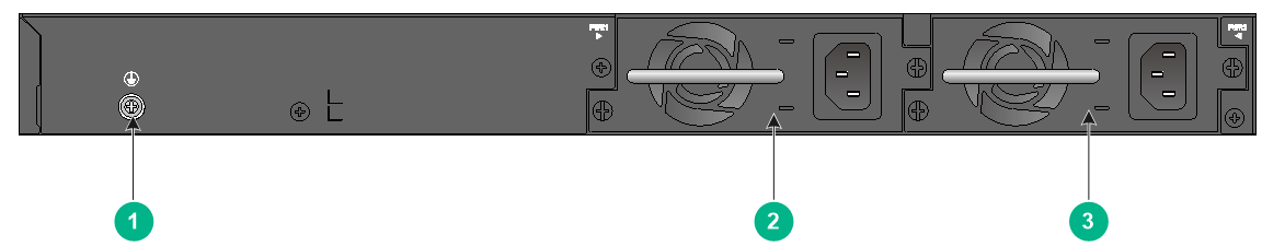
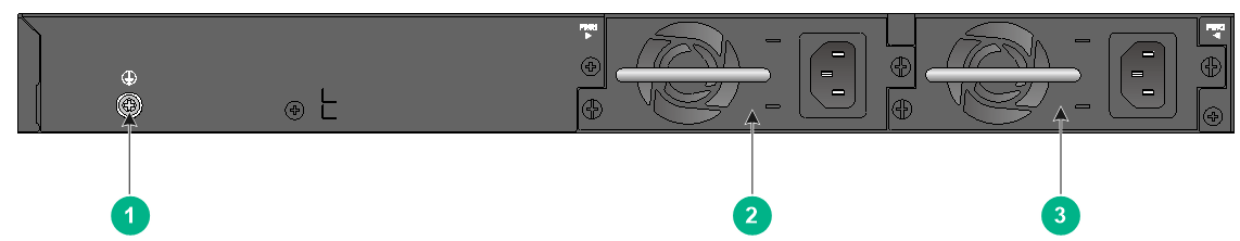
Figure2-2 Rear panel
|
(1) Grounding screw |
(2) Power supply 1 (PWR1) |
|
(3) Power supply 2 (PWR2) |
|
The S5560S-28F-EI switch comes with power supply slot 1 empty and power supply slot 2 installed with a filler panel. You can install one or two power supplies for the switch as required. In this figure, two PSR150-A1 AC power supplies are installed in the power supply slots.
S5560S-52F-EI
Figure2-3 Front panel
|
(1) SFP port |
(2) SFP port LED |
|
(3) 10/100/1000BASE-T autosensing Ethernet port |
|
|
(4) 10/100/1000BASE-T autosensing Ethernet port LED |
|
|
(5) Console port (CONSOLE) |
(6) Micro USB console port |
|
(7) System status LED (SYS) |
(8) Power supply 2 status LED (PWR2) |
|
(9) Power supply 1 status LED (PWR1) |
(10) SFP+ port |
|
(11) SFP+ port LED |
|
Figure2-4 Rear panel
|
(1) Grounding screw |
(2) Power supply 1 (PWR1) |
|
(3) Power supply 2 (PWR2) |
|
The S5560S-52F-EI switch comes with power supply slot 1 empty and power supply slot 2 installed with a filler panel. You can install one or two power supplies for the switch as required. In this figure, two PSR150-A1 AC power supplies are installed in the power supply slots.
S5560S-28P-EI
Figure2-5 Front panel
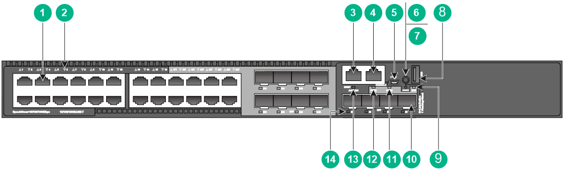
|
(1) 10/100/1000BASE-T autosensing Ethernet port |
|
|
(2) 10/100/1000BASE-T autosensing Ethernet port LED |
|
|
(3) Management Ethernet port |
(4) Console port (CONSOLE) |
|
(5) Micro USB console port |
(6) Port LED mode switching button |
|
(7) Mode LED (MODE) |
(8) USB port |
|
(9) System status LED (SYS) |
(10) SFP port |
|
(11) Power supply 2 status LED (PWR2) |
(12) Power supply 1 status LED (PWR1) |
|
(13) Management Ethernet port LED (ACT/LINK) |
(14) SFP port LED |
Figure2-6 Rear panel

|
(1) Grounding screw |
(2) Power supply 1 |
|
(3) Power supply 2 |
|
The S5560S-28P-EI switch comes with power supply slot 1 empty and power supply slot 2 installed with a filler panel. You can install one or two power supplies for the switch as required. In this figure, two PSR150-A1 AC power supplies are installed in the power supply slots.
S5560S-52P-EI
Figure2-7 Front panel
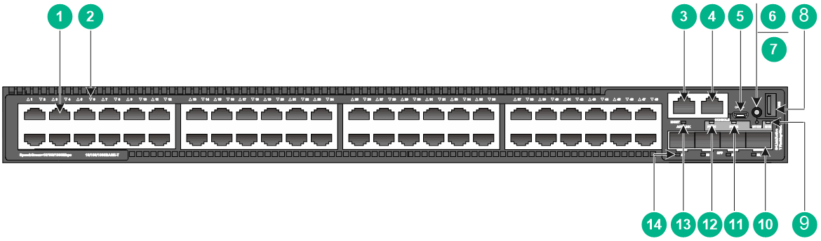
|
(1) 10/100/1000BASE-T autosensing Ethernet port |
|
|
(2) 10/100/1000BASE-T autosensing Ethernet port LED |
|
|
(3) Management Ethernet port |
(4) Console port (CONSOLE) |
|
(5) Micro USB console port |
(6) Port LED mode switching button |
|
(7) Mode LED (MODE) |
(8) USB port |
|
(9) System status LED (SYS) |
(10) SFP port |
|
(11) Power supply 2 status LED (PWR2) |
(12) Power supply 1 status LED (PWR1) |
|
(13) Management Ethernet port LED (ACT/LINK) |
(14) SFP port LED |
Figure2-8 Rear panel

|
(1) Grounding screw |
(2) Power supply 1 |
|
(3) Power supply 2 |
|
The S5560S-52P-EI switch comes with power supply slot 1 empty and power supply slot 2 installed with a filler panel. You can install one or two power supplies for the switch as required. In this figure, two PSR150-A1 AC power supplies are installed in the power supply slots.
S5560S-28S-EI
Figure2-9 Front panel
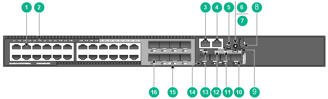
|
(1) 10/100/1000BASE-T autosensing Ethernet port |
|
|
(2) 10/100/1000BASE-T autosensing Ethernet port LED |
|
|
(3) Management Ethernet port |
(4) Console port (CONSOLE) |
|
(5) Micro USB console port |
(6) Port LED mode switching button |
|
(7) Mode LED (MODE) |
(8) USB port |
|
(9) System status LED (SYS) |
(10) SFP+ port |
|
(11) Power supply 2 status LED (PWR2) |
(12) Power supply 1 status LED (PWR1) |
|
(13) Management Ethernet port LED (ACT/LINK) |
(14) SFP+ port LED |
|
(15) SFP port LED |
(16) SFP port |
Figure2-10 Rear panel

|
(1) Grounding screw |
(2) Power supply 1 |
|
(3) Power supply 2 |
|
The S5560S-28S-EI switch comes with power supply slot 1 empty and power supply slot 2 installed with a filler panel. You can install one or two power supplies for the switch as required. In this figure, two PSR150-A1 AC power supplies are installed in the power supply slots.
S5560S-52S-EI
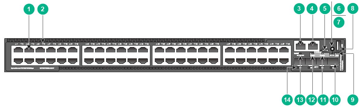
Figure2-11 Front panel

|
(1) 10/100/1000BASE-T autosensing Ethernet port |
|
|
(2) 10/100/1000BASE-T autosensing Ethernet port LED |
|
|
(3) Management Ethernet port |
(4) Console port (CONSOLE) |
|
(5) Micro USB console port |
(6) Port LED mode switching button |
|
(7) Mode LED (MODE) |
(8) USB port |
|
(9) System status LED (SYS) |
(10) SFP+ port |
|
(11) Power supply 2 status LED (PWR2) |
(12) Power supply 1 status LED (PWR1) |
|
(13) Management Ethernet port LED (ACT/LINK) |
(14) SFP+ port LED |
Figure2-12 Rear panel
|
(1) Grounding screw |
(2) Power supply 1 |
|
(3) Power supply 2 |
|
The S5560S-52S-EI switch comes with power supply slot 1 empty and power supply slot 2 installed with a filler panel. You can install one or two power supplies for the switch as required. In this figure, two PSR150-A1 AC power supplies are installed in the power supply slots.
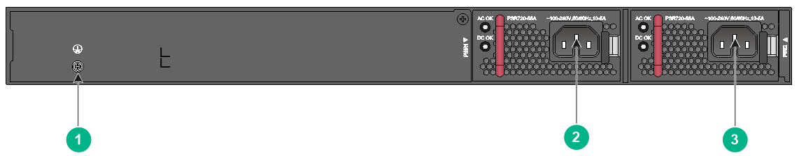
S5560S-28S-PWR-EI
Figure2-13 Front panel

|
(1) 10/100/1000BASE-T autosensing Ethernet port |
|
|
(2) 10/100/1000BASE-T autosensing Ethernet port LED |
|
|
(3) SFP port |
(4) SFP port LED |
|
(5) Management Ethernet port |
(6) Console port (CONSOLE) |
|
(7) Micro USB console port |
(8) Port LED mode switching button |
|
(9) Mode LED (MODE) |
(10) USB port |
|
(11) System status LED (SYS) |
(12) SFP+ port |
|
(13) Power supply 2 status LED (PWR2) |
(14) Power supply 1 status LED (PWR1) |
|
(15) Management Ethernet port LED (ACT/LINK) |
(16) SFP+ port LED |
Figure2-14 Rear panel

|
(1) Grounding screw |
(2) Power supply 1 |
|
(3) Power supply 2 |
|
The S5560S-28S-PWR-EI switch comes with power supply slot 1 empty and power supply slot 2 installed with a filler panel. You can install one or two power supplies for the switch as required. In this figure, two PSR720-56A AC power supplies are installed in the power supply slots.
S5560S-52S-PWR-EI
Figure2-15 Front panel
|
(1) 10/100/1000BASE-T autosensing Ethernet port |
|
|
(2) 10/100/1000BASE-T autosensing Ethernet port LED |
|
|
(3) Management Ethernet port |
(4) Console port (CONSOLE) |
|
(5) Micro USB console port |
(6) Port LED mode switching button |
|
(7) Mode LED (MODE) |
(8) USB port |
|
(9) System status LED (SYS) |
(10) SFP+ port |
|
(11) Power supply 2 status LED (PWR2) |
(12) Power supply 1 status LED (PWR1) |
|
(13) Management Ethernet port LED (ACT/LINK) |
(14) SFP+ port LED |
Figure2-16 Rear panel

|
(1) Grounding screw |
(2) Power supply 1 |
|
(3) Power supply 2 |
|
The S5560S-52S-PWR-EI switch comes with power supply slot 1 empty and power supply slot 2 installed with a filler panel. You can install one or two power supplies for the switch as required. In this figure, two PSR720-56A AC power supplies are installed in the power supply slots.
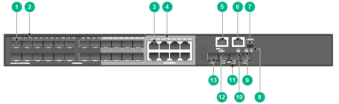
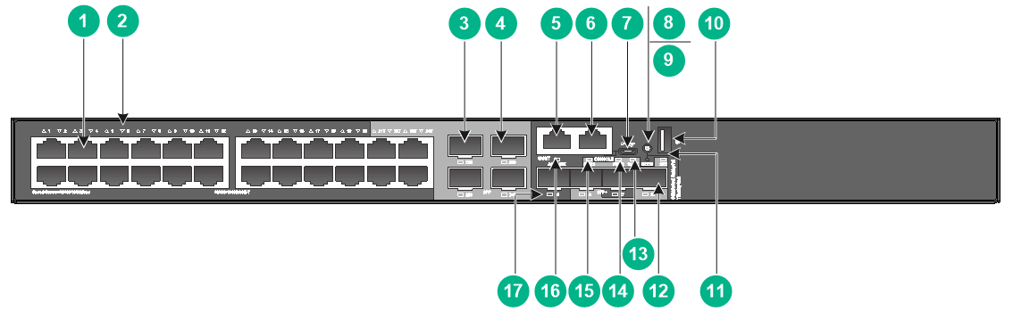
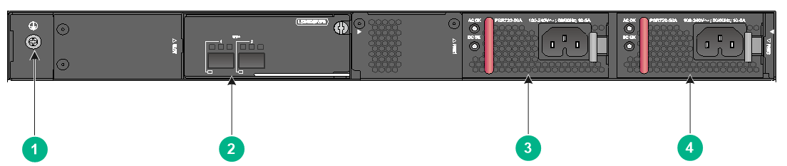
S5130S-28C-HI
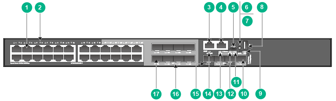
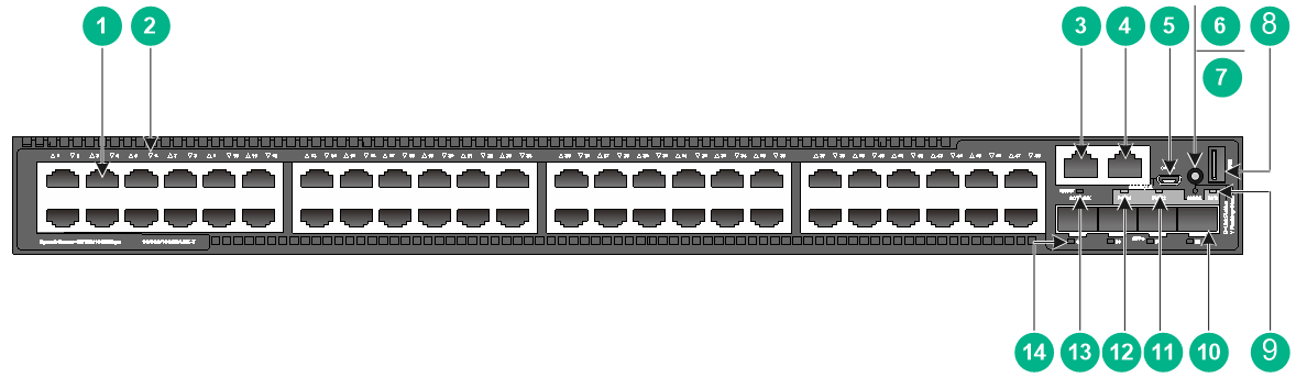
Figure2-17 Front panel
|
(1) 10/100/1000BASE-T autosensing Ethernet port |
|
|
(2) 10/100/1000BASE-T autosensing Ethernet port LED |
|
|
(3) Management Ethernet port |
(4) Console port (CONSOLE) |
|
(5) Micro USB console port |
(6) Port LED mode switching button |
|
(7) Mode LED (MODE) |
(8) USB port |
|
(9) System status LED (SYS) |
(10) SFP+ port |
|
(11) Expansion slot LED (SLOT) |
(12) Power supply 2 status LED (PWR2) |
|
(13) Power supply 1 status LED (PWR1) |
(14) Management Ethernet port LED (ACT/LINK) |
|
(15) SFP+ port LED |
(16) SFP port LED |
|
(17) SFP port |
|
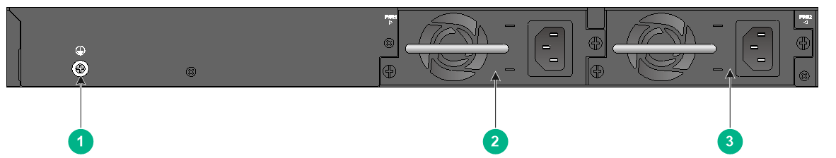
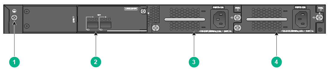
Figure2-18 Rear panel

|
(1) Grounding screw |
(2) Expansion module |
|
(3) Power supply 1 (PWR1) |
(4) Power supply 2 (PWR2) |
The S5130S-28C-HI switch comes with power supply slot 1 empty and power supply slot 2 installed with a filler panel. You can install one or two power supplies for the switch as required. In this figure, two PSR75-12A AC power supplies are installed in the power supply slots.
The S5130S-28C-HI switch provides an expansion slot at the rear panel. It comes with a filler panel installed in this expansion slot. You can install one expansion module as needed. In this figure, an LSWM2SP2PB interface module is installed.
S5130S-28S-HI
Figure2-19 Front panel

|
(1) 10/100/1000BASE-T autosensing Ethernet port |
|
|
(2) 10/100/1000BASE-T autosensing Ethernet port LED |
|
|
(3) Management Ethernet port |
(4) Console port (CONSOLE) |
|
(5) Micro USB console port |
(6) Port LED mode switching button |
|
(7) Mode LED (MODE) |
(8) USB port |
|
(9) System status LED (SYS) |
(10) SFP+ port |
|
(11) Power supply 2 status LED (PWR2) |
(12) Power supply 1 status LED (PWR1) |
|
(13) Management Ethernet port LED (ACT/LINK) |
(14) SFP+ port LED |
|
(15) SFP port LED |
(16) SFP port |
Figure2-20 Rear panel

|
(1) Grounding screw |
(2) Power supply 1 |
|
(3) Power supply 2 |
|
The S5130S-28S-HI switch comes with power supply slot 1 empty and power supply slot 2 installed with a filler panel. You can install one or two power supplies for the switch as required. In this figure, two PSR150-A1 AC power supplies are installed in the power supply slots.
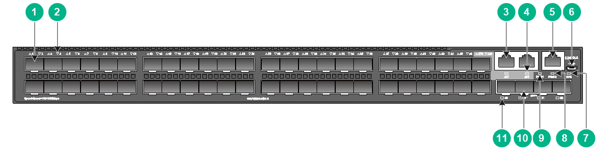
S5130S-52C-HI
Figure2-21 Front panel
|
(1) 10/100/1000BASE-T autosensing Ethernet port |
|
|
(2) 10/100/1000BASE-T autosensing Ethernet port LED |
|
|
(3) Management Ethernet port |
(4) Console port (CONSOLE) |
|
(5) Micro USB console port |
(6) Port LED mode switching button |
|
(7) Mode LED (MODE) |
(8) USB port |
|
(9) System status LED (SYS) |
(10) SFP+ port |
|
(11) SFP+ port LED |
(12) Expansion slot LED (SLOT) |
|
(13) Power supply 2 status LED (PWR2) |
(14) Power supply 1 status LED (PWR1) |
|
(15) SFP port |
(16) Management Ethernet port LED (ACT/LINK) |
|
(17) SFP port LED |
|
Figure2-22 Rear panel
|
(1) Grounding screw |
(2) Expansion module |
|
(3) Power supply 1 (PWR1) |
(4) Power supply 2 (PWR2) |
The S5130S-52C-HI switch comes with power supply slot 1 empty and power supply slot 2 installed with a filler panel. You can install one or two power supplies for the switch as required. In this figure, two PSR75-12A AC power supplies are installed in the power supply slots.
The S5130S-52C-HI switch provides an expansion slot at the rear panel. It comes with this expansion slot installed with a filler panel. You can install one expansion module as needed. In this figure, an LSWM2SP2PB interface module is installed.
S5130S-52S-HI
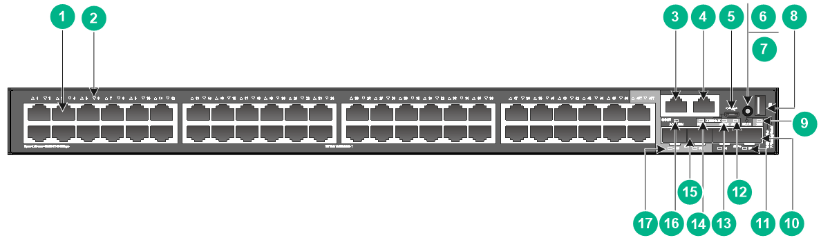
Figure2-23 Front panel
|
(1) 10/100/1000BASE-T autosensing Ethernet port |
|
|
(2) 10/100/1000BASE-T autosensing Ethernet port LED |
|
|
(3) Management Ethernet port |
(4) Console port (CONSOLE) |
|
(5) Micro USB console port |
(6) Port LED mode switching button |
|
(7) Mode LED (MODE) |
(8) USB port |
|
(9) System status LED (SYS) |
(10) SFP+ port |
|
(11) Power supply 2 status LED (PWR2) |
(12) Power supply 1 status LED (PWR1) |
|
(13) Management Ethernet port LED (ACT/LINK) |
(14) SFP+ port LED |
Figure2-24 Rear panel

|
(1) Grounding screw |
(2) Power supply 1 |
|
(3) Power supply 2 |
|
The S5130S-52S-HI switch comes with power supply slot 1 empty and power supply slot 2 installed with a filler panel. You can install one or two power supplies for the switch as required. In this figure, two PSR150-A1 AC power supplies are installed in the power supply slots.
S5130S-28S-PWR-HI
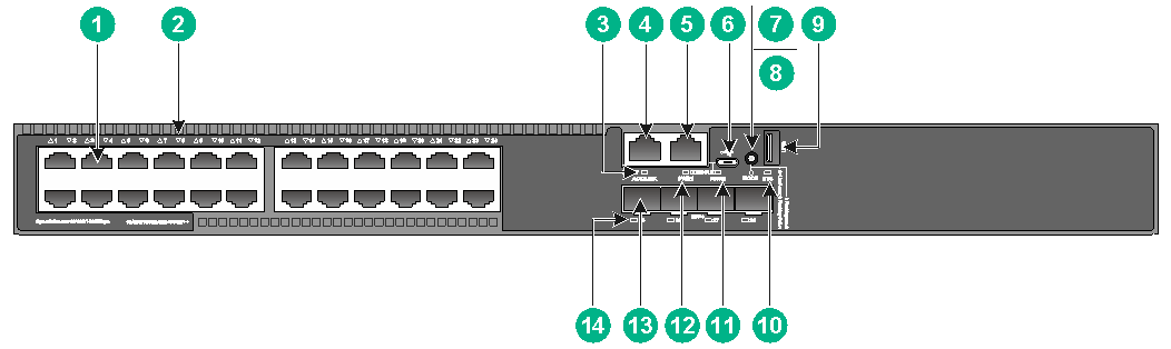
Figure2-25 Front panel
|
(1) 10/100/1000BASE-T autosensing Ethernet port |
|
|
(2) 10/100/1000BASE-T autosensing Ethernet port LED |
|
|
(3) SFP port |
(4) SFP port LED |
|
(5) Management Ethernet port |
(6) Console port (CONSOLE) |
|
(7) Micro USB console port |
(8) Port LED mode switching button |
|
(9) Mode LED (MODE) |
(10) USB port |
|
(11) System status LED (SYS) |
(12) SFP+ port |
|
(13) Power supply 2 status LED (PWR2) |
(14) Power supply 1 status LED (PWR1) |
|
(15) Management Ethernet port LED (ACT/LINK) |
(16) SFP+ port LED |
Figure2-26 Rear panel

|
(1) Grounding screw |
(2) Power supply 1 |
|
(3) Power supply 2 |
|
The S5130S-28S-PWR-HI switch comes with power supply slot 1 empty and power supply slot 2 installed with a filler panel. You can install one or two power supplies for the switch as required. In this figure, two PSR720-56A AC power supplies are installed in the power supply slots.
S5130S-28S-UPWR-HI
Figure2-27 Front panel
|
(1) 10/100/1000BASE-T autosensing Ethernet port |
|
|
(2) 10/100/1000BASE-T autosensing Ethernet port LED |
|
|
(3) Management Ethernet port LED (ACT/LINK) |
(4) Management Ethernet port |
|
(5) Console port (CONSOLE) |
(6) Micro USB console port |
|
(7) Port LED mode switching button |
(8) Mode LED (MODE) |
|
(9) USB port |
(10) System status LED (SYS) |
|
(11) Power supply 2 status LED (PWR2) |
(12) Power supply 1 status LED (PWR1) |
|
(13) SFP+ port |
(14) SFP+ port LED |
Figure2-28 Rear panel

|
(1) Grounding screw |
(2) Power supply 1 |
|
(3) Power supply 2 |
|
The S5130S-28S-UPWR-HI switch comes with power supply slot 1 empty and power supply slot 2 installed with a filler panel. You can install one or two power supplies for the switch as required. In this figure, two PSR720-56A AC power supplies are installed in the power supply slots.
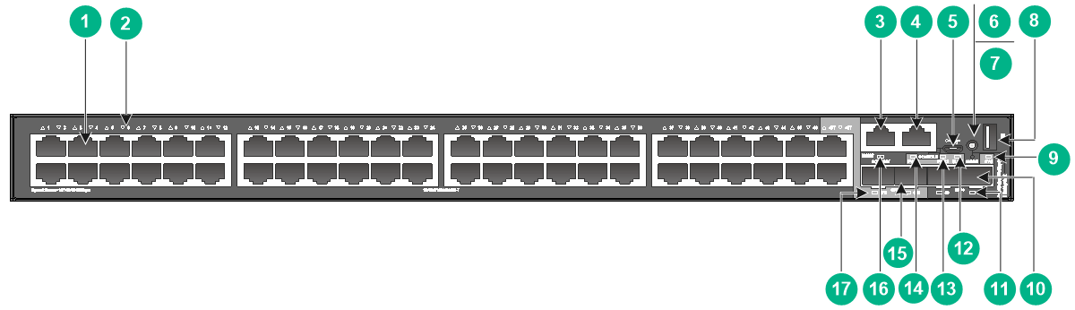
S5130S-52S-PWR-HI
Figure2-29 Front panel

|
(1) 10/100/1000BASE-T autosensing Ethernet port |
|
|
(2) 10/100/1000BASE-T autosensing Ethernet port LED |
|
|
(3) Management Ethernet port |
(4) Console port (CONSOLE) |
|
(5) Micro USB console port |
(6) Port LED mode switching button |
|
(7) Mode LED (MODE) |
(8) USB port |
|
(9) System status LED (SYS) |
(10) SFP+ port |
|
(11) Power supply 2 status LED (PWR2) |
(12) Power supply 1 status LED (PWR1) |
|
(13) Management Ethernet port LED (ACT/LINK) |
(14) SFP+ port LED |
Figure2-30 Rear panel
|
(1) Grounding screw |
(2) Power supply 1 |
|
(3) Power supply 2 |
|
The S5130S-52S-PWR-HI switch comes with power supply slot 1 empty and power supply slot 2 installed with a filler panel. You can install one or two power supplies for the switch as required. In this figure, two PSR720-56A AC power supplies are installed in the power supply slots.
S5130S-28C-PWR-HI
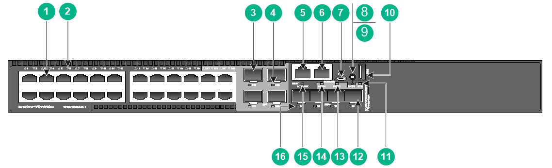
Figure2-31 Front panel
|
(1) 10/100/1000BASE-T autosensing Ethernet port |
|
|
(2) 10/100/1000BASE-T autosensing Ethernet port LED |
|
|
(3) SFP port |
(4) SFP port LED |
|
(5) Management Ethernet port |
(6) Console port (CONSOLE) |
|
(7) Micro USB console port |
(8) Port LED mode switching button |
|
(9) Mode LED (MODE) |
(10) USB port |
|
(11) System status LED (SYS) |
(12) SFP+ port |
|
(13) Expansion slot LED (SLOT) |
(14) Power supply 2 status LED (PWR2) |
|
(15) Power supply 1 status LED (PWR1) |
(16) Management Ethernet port LED (ACT/LINK) |
|
(17) SFP+ port LED |
|
Figure2-32 Rear panel
|
(1) Grounding screw |
(2) Expansion module |
|
(3) Power supply 1 (PWR1) |
(4) Power supply 2 (PWR2) |
The S5130S-28C-PWR-HI switch comes with power supply slot 1 empty and power supply slot 2 installed with a filler panel. You can install one or two power supplies for the switch as required. In this figure, two PSR720-56A AC power supplies are installed in the power supply slots.
The S5130S-28C-PWR-HI switch provides an expansion slot at the rear panel. It comes with this expansion slot installed with a filler panel. You can install one expansion module as needed. In this figure, an LSWM2SP2PB interface module is installed.
S5130S-52C-PWR-HI
Figure2-33 Front panel
|
(1) 10/100/1000BASE-T autosensing Ethernet port |
|
|
(2) 10/100/1000BASE-T autosensing Ethernet port LED |
|
|
(3) Management Ethernet port |
(4) Console port (CONSOLE) |
|
(5) Micro USB console port |
(6) Port LED mode switching button |
|
(7) Mode LED (MODE) |
(8) USB port |
|
(9) System status LED (SYS) |
(10) SFP+ port |
|
(11) SFP+ port LED |
(12) Expansion slot LED (SLOT) |
|
(13) Power supply 2 status LED (PWR2) |
(14) Power supply 1 status LED (PWR1) |
|
(15) SFP port |
(16) Management Ethernet port LED (ACT/LINK) |
|
(17) SFP port LED |
|
Figure2-34 Rear panel

|
(1) Grounding screw |
(2) Expansion module |
|
(3) Power supply 1 (PWR1) |
(4) Power supply 2 (PWR2) |
The S5130S-52C-PWR-HI switch comes with power supply slot 1 empty and power supply slot 2 installed with a filler panel. You can install one or two power supplies for the switch as required. In this figure, two PSR720-56A AC power supplies are installed in the power supply slots.
The S5130S-52C-PWR-HI switch provides an expansion slot at the rear panel. It comes with this expansion slot installed with a filler panel. You can install one expansion module as needed. In this figure, an LSWM2SP2PB interface module is installed.
3 Removable components and compatibility matrixes
Removable components and their compatibility with the device
Table3-1 Removable components and their compatibility with the S5560S-EI series
|
Removable component |
Non-PoE switches of the S5560S-EI series |
PoE switches of the S5560S-EI series |
|
Removable power supplies |
||
|
PSR75-12A |
Supported |
Not supported |
|
PSR150-A1 |
Supported |
Not supported |
|
PSR150-D1 |
Supported |
Not supported |
|
PSR180-56A |
Not supported |
Supported |
|
PSR360-56A |
Not supported |
Supported |
|
PSR560-56D |
Not supported |
Supported |
|
PSR720-56A |
Not supported |
Supported |
|
PSR1110-56A |
Not supported |
Supported |
Table3-2 Removable components and their compatibility with the S5130S-HI series
|
Removable components |
S5130S-28S-HI |
S5130S-28C-HI |
S5130S-28S-UPWR-HI |
S5130S-28S-PWR-HI |
S5130S-28C-PWR-HI |
|
Removable power supplies |
|||||
|
PSR75-12A |
Supported |
Supported |
Not supported |
Not supported |
Not supported |
|
PSR150-A1 |
Supported |
Not supported |
Not supported |
Not supported |
Not supported |
|
PSR150-D1 |
Supported |
Supported |
Not supported |
Not supported |
Not supported |
|
PSR180-56A |
Not supported |
Not supported |
Not supported |
Supported |
Supported |
|
PSR360-56A |
Not supported |
Not supported |
Supported |
Supported |
Supported |
|
PSR560-56D |
Not supported |
Not supported |
Supported |
Supported |
Supported |
|
PSR720-56A |
Not supported |
Not supported |
Supported |
Supported |
Supported |
|
PSR1110-56A |
Not supported |
Not supported |
Supported |
Supported |
Supported |
|
Removable expansion modules |
|||||
|
LSWM2SP2PB |
Not supported |
Supported |
Not supported |
Not supported |
Supported |
You can install one power supply, or two power supplies for redundancy on a non-PoE switch. These switches support mix of an AC power supply and a DC power supply.
You can install one power supply, or two power supplies for redundancy on the S5130S-28S-PWR-HI and S5130S-52S-PWR-HI PoE switches. The PoE capabilities of these switches vary by power supply configuration. For more information, see Table1-7.
If the PSR180-56A is used together with a PSR360-56A, PSR560-56D, PSR720-56A, or PSR1110-56A, the total power output equals the output of two PSR180-56A power supplies.
Power supplies
Table3-3 Power supplies
|
Power supply |
Specifications |
Reference |
|
PSR75-12A |
· Rated input voltage range: ¡ AC: 100 VAC to 240 VAC @ 50 Hz or 60 Hz ¡ DC: 240 VDC · Max input voltage range: ¡ AC: 90 VAC to 290 VAC @ 47 Hz to 63 Hz ¡ DC: 180 VDC to 320 VDC · Max output power: 75 W |
H3C PSR75-12A Power Module User Manual |
|
PSR150-A1 |
· Rated input voltage range: 100 VAC to 240 VAC @ 50 Hz or 60 Hz · Max input voltage range: 90 VAC to 264 VAC @ 47 Hz to 63 Hz · Max output power: 150 W |
H3C PSR150-A & PSR150-D Series Power Supplies User Manual |
|
PSR150-D1 |
· Rated input voltage range: –48 VDC to –60 VDC · Max input voltage range: –36 VDC to –72 VDC · Max output power: 150 W |
H3C PSR150-A & PSR150-D Series Power Supplies User Manual |
|
PSR180-56A |
· Rated input voltage range: ¡ AC: 100 VAC to 240 VAC @ 50 or 60 Hz ¡ DC: 240 VDC · Max input voltage range: ¡ AC: 85 VAC to 290 VAC @ 47 Hz to 63 Hz ¡ DC: 180 VDC to 320 VDC · Max output power: 180 W |
H3C PSR180-56A Power Module User Manual |
|
PSR360-56A |
· Rated input voltage range: 100 VAC to 240 VAC @ 50 Hz or 60 Hz · Max input voltage range: 90 VAC to 264 VAC @ 47 Hz to 63 Hz · Max output power: 360 W |
H3C PSR360-56A Power Module User Manual |
|
PSR560-56D |
· Rated input voltage range: –48 VDC to –60 VDC · Max input voltage range: –36 VDC to –72 VDC · Max output power: 560 W |
H3C PSR560-56D Power Module User Manual |
|
PSR720-56A |
· Rated input voltage range: 100 VAC to 240 VAC @ 50 Hz or 60 Hz · Max input voltage range: 90 VAC to 264 VAC @ 47 Hz to 63 Hz · Max output power: 720 W |
H3C PSR720-56A Power Module User Manual |
|
PSR1110-56A |
· Rated input voltage range: 115 VAC to 240 VAC @ 50 Hz or 60 Hz · Max input voltage range: 102.5 VAC to 264 VAC @ 47 Hz to 63 Hz · Max output power: 1110 W |
H3C PSR1110-56A Power Module User Manual |
|
|
NOTE: The PSR1110-56A power supply adds 64 mm (2.52 in) to the total depth of the switch, which includes the power supply handle. |
Expansion modules
Table3-4 Expansion modules
|
Model |
Description |
Port quantity |
Available transceiver modules and cables |
Reference |
|
LSWM2SP2PB |
2-port 10-Gigabit SPF+ fiber Ethernet interface module |
2 |
· 10-GE SFP+ module · 10-GE SFP+ cable · GE SFP module · GE SFP cable |
H3C LSWM2SP2PB & LSWM2SP4PB Interface Cards User Manual. |
|
|
IMPORTANT: By default, the operating mode is 0 for the expansion module on an S5130S-28C-HI or S5130S-28C-PWR-HI switch. In this mode, ports 26 and 28 on the front panel are available, and none of the ports on the expansion module is available. To use ports on the expansion module, execute the port-configuration-mode command to set the operating mode to 1 and then reboot the switch. After the configuration, ports 26 and 28 on the front panel become unavailable. For more information, see the Layer 2—LAN switching configuration guide of the device. |
4 Ports and LEDs
Ports
Console port
The switch has two console ports: a serial console port and a Micro USB console port.
Table4-1 Console port specifications
|
Item |
Serial console port |
Micro USB console port |
|
Connector type |
RJ-45 |
Micro USB Type B |
|
Compliant standard |
EIA/TIA-232 |
USB 2.0 |
|
Transmission baud rate |
9600 bps (default) to 115200 bps |
|
|
Services |
· Provides connection to an ASCII terminal. · Provides connection to the serial port of a local PC running terminal emulation program. |
Provides connection to the USB port of a local PC running terminal emulation program. |
Management Ethernet port
All S5560S-EI and S5130S-HI switches except the S5560S-52F-EI switch each provide a management Ethernet port on the front panel. You can connect this port to a PC or management station for loading and debugging software or remote management.
Table4-2 Management Ethernet port specifications
|
Item |
Specification |
|
Connector type |
RJ-45 |
|
Connector quantity |
1 |
|
Port transmission rate |
10/100 Mbps, half/full duplex MDI/MDI-X, autosensing |
|
Transmission medium and max transmission distance |
100 m (328.08 ft) over category-5 twisted pair cable |
|
Functions and services |
Switch software and Boot ROM upgrade, network management |
USB port
All S5560S-EI and S5130S-HI switches except the S5560S-28F-EI and S5560S-52F-EI switches each have one OHC-compliant USB2.0 port that can upload and download data at a rate up to 480 Mbps. You can use this USB port to access the file system on the flash of the switch, for example, to upload or download application and configuration files.
|
|
NOTE: USB devices from different vendors vary in compatibilities and drivers. H3C does not guarantee the correct operation of USB devices from all vendors on the switch. If a USB device fails to operate on the switch, replace it with one from another vendor. |
10/100/1000BASE-T autosensing Ethernet port
Table4-3 10/100/1000BASE-T autosensing Ethernet port specifications
|
Item |
Specification |
|
Connector type |
RJ-45 |
|
Interface attributes |
· 10 Mbps, full duplex · 100 Mbps, full duplex · 1000 Mbps, full duplex · MDI/MDI-X, auto-sensing |
|
Max transmission distance |
100 m (328.08 ft) |
|
Transmission medium |
Category-5 (or above) twisted pair cable |
|
Standards |
IEEE 802.3i, 802.3u, 802.3ab |
SFP port
|
|
CAUTION: Make sure the ambient temperature for an operating S5560S-28F-EI does not exceed 40°C (104°F) if the following conditions exist: · The switch uses one or two PSR75-12A power supplies for power supply. · The switch uses transceiver modules with a maximum transmission distance greater than or equal to 80 km (49.71 miles). |
|
|
CAUTION: Make sure the ambient temperature for an operating S5560S-52F-EI does not exceed 40°C (104°F) if the following conditions exist: · The switch uses one or two PSR75-12A power supplies for power supply. · The switch uses transceiver modules. |
The following switches provide fixed SFP ports on the front panel. You can install the FE SFP modules in Table4-4 or GE SFP transceiver modules and cables in Table4-5 in the SFP ports:
· S5560S-28F-EI
· S5560S-52F-EI
· S5560S-28S-EI
· S5560S-28P-EI
· S5560S-52P-EI
· S5560S-28S-PWR-EI
· S5130S-28S-HI
· S5130S-28S-PWR-HI
· S5130S-28C-HI
· S5130S-52C-HI
· S5130S-28C-PWR-HI
· S5130S-52C-PWR-HI
The following SFP ports support only GE SFP transceiver modules and cables in Table4-5:
· SFP ports 25 to 28 on the S5560S-28P-EI.
· All SFP ports on the S5560S-52P-EI.
Table4-4 FE SFP transceiver modules available for the SFP ports
|
FE SFP module |
Central wavelength (nm) |
Connector |
Fiber diameter (µm) |
Max transmission distance |
|
SFP-FE-SX-MM1310-A |
1310 |
LC |
Multi-mode, 50/125 |
2 km (1.24 miles) |
|
Multi-mode, 62.5/125 |
||||
|
SFP-FE-LX-SM1310-A |
1310 |
LC |
Single-mode, 9/125 |
15 km (9.32 miles) |
|
SFP-FE-LX-SM1310-D |
1310 |
LC |
Single-mode, 9/125 |
15 km (9.32 miles) |
|
SFP-FE-LH40-SM1310 |
1310 |
LC |
Single-mode, 9/125 |
40 km (24.86 miles) |
|
SFP-FE-LH80-SM1550 |
1550 |
LC |
Single-mode, 9/125 |
80 km (49.71 miles) |
|
SFP-FE-LX-SM1310-BIDI |
TX: 1310 RX: 1550 |
LC |
Single-mode, 9/125 |
15 km (9.32 miles) |
|
SFP-FE-LX-SM1550-BIDI |
TX: 1550 RX: 1310 |
|
|
IMPORTANT: The SFP-FE-LX-SM1310-BIDI and SFP-FE-LX-SM1550-BIDI modules must be used in pairs. |
Table4-5 GE SFP transceiver modules and cables available for the SFP ports
|
GE SFP transceiver module and cable |
Central wavelength (nm) |
Connector |
Cable/Fiber type and diameter (µm) |
Modal bandwidth (MHz × km) |
Max transmission distance |
|
SFP copper transceiver module |
|||||
|
SFP-GE-T |
N/A |
RJ-45 |
Twisted pair cable |
N/A |
100 m (328.08 ft) |
|
SFP-GE-T-D |
N/A |
RJ-45 |
Twisted pair cable |
N/A |
100 m (328.08 ft) |
|
SFP fiber transceiver module |
|||||
|
SFP-GE-SX-MM850-A |
850 |
LC |
Multi-mode, 50/125 |
500 |
550 m (1804.46 ft) |
|
400 |
500 m (1640.42 ft) |
||||
|
Multi-mode, 62.5/125 |
200 |
275 m (902.23 ft) |
|||
|
160 |
220 m (721.78 ft) |
||||
|
SFP-GE-SX-MM850-D |
850 |
LC |
Multi-mode, 50/125 |
500 |
550 m (1804.46 ft) |
|
400 |
500 m (1640.42 ft) |
||||
|
Multi-mode, 62.5/125 |
200 |
275 m (902.23 ft) |
|||
|
160 |
220 m (721.78 ft) |
||||
|
SFP-GE-SX-MM850-S |
850 |
LC |
Multi-mode, 50/125 |
500 |
550 m (1804.46 ft) |
|
400 |
500 m (1640.42 ft) |
||||
|
Multi-mode, 62.5/125 |
200 |
275 m (902.23 ft) |
|||
|
160 |
220 m (721.78 ft) |
||||
|
SFP-GE-LX-SM1310-A |
1310 |
LC |
Single-mode, 9/125 |
N/A |
10 km (6.21 miles) |
|
Multi-mode, 50/125 |
500 or 400 |
550 m (1804.46 ft) |
|||
|
Multi-mode, 62.5/125 |
500 |
550 m (1804.46 ft) |
|||
|
SFP-GE-LX-SM1310-D |
1310 |
LC |
Single-mode, 9/125 |
N/A |
10 km (6.21 miles) |
|
SFP-GE-LX-SM1310-S |
1310 |
LC |
Single-mode, 9/125 |
N/A |
10 km (6.21 miles) |
|
SFP-GE-LH40-SM1310 |
1310 |
LC |
Single-mode, 9/125 |
N/A |
40 km (24.86 miles) |
|
SFP-GE-LH40-SM1310-D |
1310 |
LC |
Single-mode, 9/125 |
N/A |
40 km (24.86 miles) |
|
SFP-GE-LH40-SM1550 |
1550 |
LC |
Single-mode, 9/125 |
N/A |
40 km (24.86 miles) |
|
SFP-GE-LH80-SM1550 |
1550 |
LC |
Single-mode, 9/125 |
N/A |
80 km (49.71 miles) |
|
SFP-GE-LH80-SM1550-D |
1550 |
LC |
Single-mode, 9/125 |
N/A |
80 km (49.71 miles) |
|
SFP-GE-LH100-SM1550 |
1550 |
LC |
Single-mode, 9/125 |
N/A |
100 km (62.14 miles) |
|
SFP-GE-LX-SM1310-BIDI |
TX: 1310 nm RX: 1490 nm |
LC |
Single-mode, 9/125 |
N/A |
10 km (6.21 miles) |
|
SFP-GE-LX-SM1490-BIDI |
TX: 1490 nm RX: 1310 nm |
LC |
Single-mode, 9/125 |
N/A |
10 km (6.21 miles) |
|
SFP-GE-LH40-SM1310-BIDI |
TX: 1310 nm RX: 1550 nm |
LC |
Single-mode, 9/125 |
N/A |
40 km (24.86 miles) |
|
SFP-GE-LH40-SM1550-BIDI |
TX: 1550 nm RX: 1310 nm |
LC |
Single-mode, 9/125 |
N/A |
40 km (24.86 miles) |
|
SFP-GE-LH70-SM1490-BIDI |
TX: 1490 nm RX: 1550 nm |
LC |
Single-mode, 9/125 |
N/A |
70 km (43.49 miles) |
|
SFP-GE-LH70-SM1550-BIDI |
TX: 1550 nm RX: 149 nm |
LC |
Single-mode, 9/125 |
N/A |
70 km (43.49 miles) |
|
SFP cable |
|||||
|
SFP-STACK-Kit |
N/A |
1.5 m (4.92 ft) |
|||
|
IMPORTANT: The SFP-GE-LX-SM1310-BIDI and SFP-GE-LX-SM1490-BIDI transceiver modules, the SFP-GE-LH40-SM1310-BIDI and SFP-GE-LH40-SM1550-BIDI transceiver modules, and the SFP-GE-LH70-SM1490-BIDI and SFP-GE-LH70-SM1550-BIDI transceiver modules must be used in pairs. For example, if one end uses an SFP-GE-LX-SM1310-BIDI transceiver module, the other end must use an SFP-GE-LX-SM1490-BIDI transceiver module. |
|
|
NOTE: · As a best practice, use only H3C SFP transceiver modules and cables for the SFP ports. · The H3C SFP transceiver modules and cables available for the SFP ports are subject to change over time. For the most recent list of SFP transceiver modules and cables available for the SFP port, contact your H3C Support or marketing staff. · For the specifications of H3C SFP transceiver modules and cables, see H3C Transceiver Modules User Guide. |
SFP+ port
The following switches each provide four fixed SFP+ ports on the front panel:
· S5560S-28F-EI
· S5560S-52F-EI
· S5560S-28S-EI
· S5560S-52S-EI
· S5560S-28S-PWR-EI
· S5560S-52S-PWR-EI
· S5130S-28C-HI
· S5130S-28S-HI
· S5130S-52S-HI
· S5130S-28C-PWR-HI
· S5130S-28S-PWR-HI
· S5130S-28S-UPWR-HI
· S5130S-52S-PWR-HI
The S5130S-52C-HI and S5130S-52C-PWR-HI switches each provide two fixed SFP+ ports on the front panel.
To connect peer SFP+ ports over a long distance, use SFP/SFP+ transceiver modules and fibers. To connect peer SFP+ ports over a short distance, use SFP+ cables. You can install the GE SFP transceiver module in Table4-5, 10-GE SFP+ transceiver modules in Table4-6, and 10-GE SFP+ cables in Table4-7 in the SFP+ ports.
Table4-6 10-GE SFP+ transceiver modules available for the SFP+ ports
|
10-GE SFP+ module |
Central wavelength (nm) |
Connector |
Fiber diameter (µm) |
Multimode fiber modal bandwidth (MHz × km) |
Max transmission distance |
|
SFP-XG-SX-MM850-D |
850 |
LC |
Multi-mode, 50/125 |
2000 |
300 m (984.25 ft) |
|
500 |
82 m (269.03 ft) |
||||
|
400 |
66 m (216.54 ft) |
||||
|
Multi-mode, 62.5/125 |
200 |
33 m (108.27 ft) |
|||
|
160 |
26 m (85.30 ft) |
||||
|
SFP-XG-SX-MM850-E |
850 |
LC |
Multi-mode, 50/125 |
2000 |
300 m (984.25 ft) |
|
500 |
82 m (269.03 ft) |
||||
|
400 |
66 m (216.54 ft) |
||||
|
Multi-mode, 62.5/125 |
200 |
33 m (108.27 ft) |
|||
|
160 |
26 m (85.30 ft) |
||||
|
SFP-XG-SX-MM850-S |
850 |
LC |
Multi-mode, 50/125 |
2000 |
300 m (984.25 ft) |
|
500 |
82 m (269.03 ft) |
||||
|
400 |
66 m (216.54 ft) |
||||
|
Multi-mode, 62.5/125 |
200 |
33 m (108.27 ft) |
|||
|
160 |
26 m (85.30 ft) |
||||
|
SFP-XG-LX-SM1310-D |
1310 |
LC |
Single-mode, 9/125 |
N/A |
10 km (6.21 miles) |
|
SFP-XG-LX-SM1310-E |
1310 |
LC |
Single-mode, 9/125 |
N/A |
10 km (6.21 miles) |
|
SFP-XG-LX-SM1310-S |
1310 |
LC |
Single-mode, 9/125 |
N/A |
10 km (6.21 miles) |
|
SFP-XG-LH40-SM1550 |
1550 |
LC |
Single-mode, 9/125 |
N/A |
40 km (24.86 miles) |
|
SFP-XG-LH40-SM1550-D |
1550 |
LC |
Single-mode, 9/125 |
N/A |
40 km (24.86 miles) |
|
SFP-XG-LH80-SM1550 |
1550 |
LC |
Single-mode, 9/125 |
N/A |
80 km (49.71 miles) |
|
SFP-XG-LH80-SM1550-D |
1550 |
LC |
Single-mode, 9/125 |
N/A |
80 km (49.71 miles) |
|
SFP-XG-LX-SM1270-BIDI |
· TX:1270 nm · RX:1330 nm |
LC |
9/125 µm single-mode optical fiber |
N/A |
10 km (6.21 miles) |
|
SFP-XG-LX-SM1330-BIDI |
· TX:1330 nm · RX:1270 nm |
LC |
9/125 µm single-mode optical fiber |
N/A |
10 km (6.21 miles) |
|
SFP-XG-LH40-SM1270-BIDI |
· TX:1270 nm · RX:1330 nm |
LC |
Single-mode, 9/125 |
N/A |
40 km (24.86 miles) |
|
SFP-XG-LH40-SM1330-BIDI |
· TX:1330 nm · RX:1270 nm |
LC |
Single-mode, 9/125 |
N/A |
40 km (24.86 miles) |
|
|
IMPORTANT: The SFP-XG-LX-SM1270-BIDI and SFP-XG-LX-SM1330-BIDI transceiver modules and the SFP-XG-LH40-SM1270-BIDI and SFP-XG-LH40-SM1330-BIDI transceiver modules must be used in pairs. For example, if one ends uses an SFP-XG-LX-SM1270-BIDI transceiver module, the other end must use an SFP-XG-LX-SM1330-BIDI transceiver module. |
Table4-7 SFP+ copper cables available for the SFP+ ports
|
SFP+ copper cable |
Cable length |
|
LSWM1STK |
0.65 m (2.13 ft) |
|
LSWM2STK |
1.2 m (3.94 ft) |
|
LSWM3STK |
3 m (9.84 ft) |
|
LSTM1STK |
5 m (16.40 ft) |
Table4-8 SFP+ fiber cables available for the SFP+ ports
|
SFP+ fiber cable |
Max transmission distance |
|
SFP-XG-D-AOC-7M |
7 m (22.97 ft) |
|
SFP-XG-D-AOC-10M |
10 m (32.81 ft) |
|
SFP-XG-D-AOC-20M |
20 m (65.62 ft) |
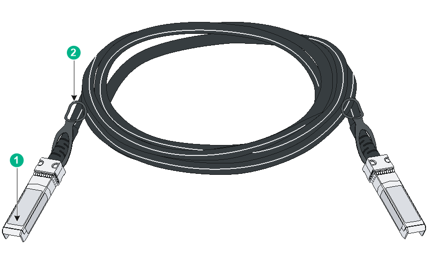
Figure4-1 SFP+ cable
|
(1) Connector |
(2) Pull latch |
|
|
NOTE: · As a best practice, use only H3C SFP/SFP+ transceiver modules and SFP+ cables for the SFP+ ports. · The H3C SFP/SFP+ transceiver modules and SFP+ cables available for the SFP+ ports are subject to change over time. For the most recent list of SFP/SFP+ transceiver modules and SFP+ cables, contact your H3C Support or marketing staff. · For the specifications of H3C SFP/SFP+ transceiver modules and SFP+ cables, see H3C Transceiver Modules User Guide. |
Combo interface
The S5560S-28F-EI, S5560S-28S-EI, S5560S-28P-EI, S5130S-28S-HI, and S5130S-28C-HI switches each provide eight combo interfaces on the front panel. The S5560S-28S-PWR-EI, S5130S-28S-PWR-HI, and S5130S-28C-PWR-HI switches each provide four combo interfaces on the front panel. The S5560S-52F-EI, S5130S-52C-HI, and S5130S-52C-PWR-HI switches each provide two combo interfaces on the front panel. A combo interface contains an SFP port and a 10/100/1000BASE-T autosensing Ethernet port. Only one of these two ports can operate at a time.
LEDs
System status LED
The system status LED shows the operating state of the switch.
Table4-9 System status LED description
|
LED mark |
Status |
Description |
|
SYS |
Steady green |
The switch is operating correctly. |
|
Flashing green (1 Hz) |
The switch is performing power-on self test (POST). |
|
|
Steady red |
The switch has failed the POST or is faulty. |
|
|
Off |
The switch is powered off. |
Power supply status LED
The switch provides two power supply slots at the rear. For each power supply, the switch provides a power supply status LED on the front panel.
Table4-10 Power supply status LED description
|
LED mark |
Status |
Description |
|
PWR1/PWR1 |
Steady green |
A power supply is installed in the power supply slot, and the power supply is outputting power correctly. |
|
Steady yellow |
A power supply is installed in the power supply slot, but the power supply has failed or no power is input to the power supply. |
|
|
Off |
No power supply is installed in the power supply slot. |
Mode LED (MODE)
All S5560S-EI and S5130S-HI series switches except the S5560S-28F-EI and S5560S-52F-EI switches each provide a mode LED (MODE) to indicate the type of information that the 10/100/1000BASE-T autosensing Ethernet port LEDs are showing.
You can use the LED mode switching button to change the indication of the mode LED.
Table4-11 Description for the mode LED
|
LED mark |
Status |
Description |
|
MODE |
Steady green |
The 10/100/1000BASE-T autosensing Ethernet port LEDs indicate the link and operating status of the port. |
|
Flashing green (available only for the S5560S-28S-PWR-EI, S5560S-52S-PWR-EI, S5130S-28S-PWR-HI, S5130S-28S-UPWR-HI, S5130S-52S-PWR-HI, S5130S-28C-PWR-HI, and S5130S-52C-PWR-HI switches) |
The 10/100/1000BASE-T autosensing Ethernet port LEDs indicates the PoE power supply status of the ports. |
|
|
Flashing yellow |
The 10/100/1000BASE-T autosensing Ethernet port LEDs indicates the IRF member ID of the switch. For example, if the LED for port 5 is steady green and the other LEDs are off, the IRF member ID of the switch is 5. |
10/100/1000BASE-T autosensing Ethernet port LED
The switch provides a status LED for each 10/100/1000BASE-T autosensing Ethernet port. The port LED and the MODE LED work in conjunction to indicate the operating status of the 10/100/1000BASE-T autosensing Ethernet port.
Table4-12 10/100/1000BASE-T autosensing Ethernet port LED description
|
MODE LED status |
10/100/1000BASE-T autosensing Ethernet port LED status |
Description |
|
Steady green (Link/Active mode) |
Steady green |
A link is present on the port. |
|
Flashing green |
The port is sending or receiving data. |
|
|
Off |
No link is present on the port. |
|
|
Flashing green (PoE mode, available only for the S5560S-28S-PWR-EI, S5560S-52S-PWR-EI, S5130S-28S-PWR-HI, S5130S-28S-UPWR-HI, S5130S-52S-PWR-H, S5130S-28C-PWR-HI, and S5130S-52C-PWR-HI switches) |
Steady green |
PoE power supply is normal. |
|
Flashing green (1 Hz) |
· The PoE power provided by the port fails to meet the power requirement of the PD. · PoE power supply overcurrent, overvoltage, or short-circuit occurs. · The remaining power of the switch fails to meet the power supply requirement of the port. |
|
|
Off |
The port is not connected to a PD or PoE is not enabled on the port. |
|
|
Flashing yellow (IRF mode) |
Steady green |
The 10/100/1000BASE-T autosensing Ethernet port LEDs on the switch work in conjunction to indicate the IRF member ID of the switch. For example, if the LED for port 5 is steady green and the other port LEDs are off, the IRF member ID of the switch is 5. |
SFP/SFP+ port LED
Table4-13 SFP/SFP+ port LED description
|
SFP/SFP+ port LED status |
Description |
|
Steady green |
A link is present on the port. |
|
Flashing green |
The port is sending or receiving data. |
|
Off |
· No link is present on the port. · The mode LED is operating in IRF mode. · The mode LED is operating in PoE mode (only for PoE switches). |
Management Ethernet port LED
Table4-14 Management Ethernet port LED description
|
Management Ethernet port LED (ACT/LINK) status |
Description |
|
Steady green |
A link is present on the port. |
|
Flashing green |
The port is sending or receiving data. |
|
Off |
No link is present on the port. |
Input status LED and output status LED on the power supply
The PSR180-56A, PSR360-56A, PSR560-56D, PSR720-56A, and PSR1110-56A power supplies each have an input status LED and an output status LED. For more information about the LEDs, see the manuals for the power supplies.
Expansion slot LED
The S5130S-28C-HI, S5130S-52C-HI, S5130S-28C-PWR-HI, and S5130S-52C-PWR-HI switches each provide an expansion slot at the rear panel. You can view the expansion slot LED on the front panel to identify the status of the installed expansion module.
Table4-15 Expansion slot status LED description
|
Expansion slot LED (SLOT) status |
Description |
|
Steady on |
An expansion module is present and is operating correctly. |
|
Flashing amber |
The expansion module is incompatible with the switch or the expansion module is faulty. |
|
Off |
No expansion module is present. |
Port status LED on the expansion module
The expansion module provides a port status LED for each port on the module. For more information about the LED, see the user guide for the expansion module.
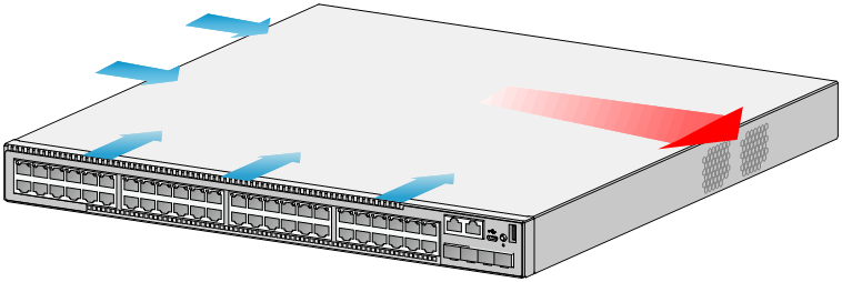
5 Cooling system
To dissipate heat timely and ensure system stability, the switch uses a high-performance cooling system. Consider the site ventilation design when you plan the installation site for the switch.
On the S5130S-28C-HI, S5130S-52C-HI, S5130S-28C-PWR-HI, S5130S-28S-UPWR-HI, and S5130S-52C-PWR-HI switches, the fan trays draw in ambient air from the left side panel and exhaust the air from the right side panel, as shown in Figure5-1.
On the other S5560S-EI & S5130S-HI series switches, the fan trays draw in ambient air from the left side and port side panels and exhaust the air from the right side panel, as shown in Figure5-2.
Figure5-1 Airflow through the S5130S-52C-HI switch
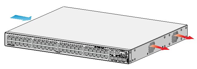
Figure5-2 Airflow through the S5130S-52S-PWR-HI switch