- Table of Contents
- Related Documents
-
| Title | Size | Download |
|---|---|---|
| 02-Hardware Information and Specifications | 4.27 MB |
1 Product models and technical specifications
Product models
H3C S5560X-EI switch series includes the following models:
· S5560X-30C-EI
· S5560X-30C-PWR-EI
· S5560X-54C-EI
· S5560X-54C-PWR-EI
· S5560X-30F-EI
· S5560X-30F-EIF
· S5560X-54F-EI
· S5560X-34S-EI
· S5560X-54S-EI
Technical specifications
Non-PoE switch models
Table1-1 Technical specifications for non-PoE switch models (1)
|
Item |
S5560X-30C-EI |
S5560X-54C-EI |
S5560X-30F-EI |
S5560X-54F-EI |
|
Dimensions (H × W × D) |
43.6 × 440 × 360 mm (1.72 × 17.32 × 14.17 in) |
43.6 × 440 × 360 mm (1.72 × 17.32 × 14.17 in) |
43.6 × 440 × 360 mm (1.72 × 17.32 × 14.17 in) |
43.6 × 440 × 360 mm (1.72 × 17.32 × 14.17 in) |
|
Weight |
≤ 6.7 kg (14.77 lb) |
≤ 7.0 kg (15.43 lb) |
≤ 6.6 kg (14.55 lb) |
≤ 6.7 kg (14.77 lb) |
|
Console port |
· 1 × micro USB console port · 1 × serial console port Only the micro USB console port is available when you connect both ports. |
|||
|
USB port |
1 |
1 |
1 |
1 |
|
Management Ethernet port |
1 |
1 |
1 |
1 |
|
SFP+ port |
4 |
4 |
4 |
4 |
|
SFP port |
8 (Each and its corresponding 10/100/1000BASE-T port form a combo interface.) |
N/A |
24 (The rightmost eight SFP ports and their corresponding 10/100/1000BASE-T autosensing Ethernet ports form combo interfaces.) |
48 |
|
10/100/1000BASE-T autosensing Ethernet port |
24 |
48 |
8 (Each and its corresponding SFP port form a combo interface.) |
N/A |
|
Expansion slot |
1, on the rear panel |
1, on the rear panel |
1, on the rear panel |
1, on the rear panel |
|
Power module slot |
2, on the rear panel |
2, on the rear panel |
2, on the rear panel |
2, on the rear panel |
|
Fan tray slot |
2, on the rear panel |
2, on the rear panel |
2, on the rear panel |
2, on the rear panel |
|
Input voltage |
· AC input for the PSR150-A1 or PSR150-A2 power module: ¡ Rated voltage range: 100 VAC to 240 VAC @ 50 Hz or 60 Hz ¡ Max voltage range: 90 VAC to 264 VAC @ 47 Hz to 63 Hz · DC input for the PSR150-D1 power module: ¡ Rated voltage range: –48 VDC to –60 VDC ¡ Max voltage range: –36 VDC to –72 VDC\ |
|||
|
Minimum power consumption |
· Single AC input: 24 W · Single DC input: 24 W · Dual AC inputs: 29 W · Dual DC inputs: 28 W |
· Single AC input: 27 W · Single DC input: 24 W · Dual AC inputs: 31 W · Dual DC inputs: 29 W |
· Single AC input: 24 W · Single DC input: 24 W · Dual AC inputs: 29 W · Dual DC inputs: 30 W |
· Single AC input: 30 W · Single DC input: 30 W · Dual AC inputs: 37 W · Dual DC inputs: 36 W |
|
Maximum power consumption |
· Single AC input: 87 W · Single DC input: 88 W · Dual AC inputs: 91 W · Dual DC inputs: 95 W |
· Single AC input: 88 W · Single DC input: 89 W · Dual AC inputs: 93 W · Dual DC inputs: 96 W |
· Single AC input: 112 W · Single DC input: 113 W · Dual AC inputs: 116 W · Dual DC inputs: 122 W |
· Single AC input: 130 W · Single DC input: 132 W · Dual AC inputs: 134 W · Dual DC inputs: 140 W |
|
Chassis leakage current compliance |
UL 62368-1/EN 62368-1/IEC 62368-1/UL 60950-1/EN 60950-1/IEC 60950-1/GB4943.1 |
|||
|
Melting current of power module fuse |
· PSR150-A1/PSR150-A2 power module: 5 A, 250 V · PSR150-D1 power module: 8 A, 250 V |
|||
|
Operating temperature |
-5°C to 45°C (23°F to 113°F) |
|||
|
Humidity |
5% RH to 95% RH, noncondensing |
|||
|
Fire resistance compliance |
UL 62368-1/EN 62368-1/IEC 62368-1/UL 60950-1/EN 60950-1/IEC 60950-1/GB4943.1 |
|||
Table1-2 Technical specifications for non-PoE switch models (2)
|
Item |
S5560X-30F-EIF |
S5560X-34S-EI |
S5560X-54S-EI |
|
Dimensions (H × W × D) |
43.6 × 440 × 220 mm (1.72 × 17.32 × 8.66 in) |
43.6 × 440 × 260 mm (1.72 × 17.32 × 10.24 in) |
43.6 × 440 × 260 mm (1.72 × 17.32 × 10.24 in) |
|
Weight |
≤ 3.2 kg (7.05 lb) |
≤ 3.6 kg (7.94 lb) |
≤ 3.9 kg (8.60 lb) |
|
Console port |
· 1 × micro USB console port · 1 × serial console port Only the micro USB console port is available when you connect both ports. |
||
|
USB port |
1 |
1 |
1 |
|
Management Ethernet port |
1 |
1 |
1 |
|
QSFP+ port |
2 |
2 |
2 |
|
SFP+ port |
4 |
4 |
4 |
|
SFP port |
24 |
4 (Each and its corresponding 10/100/1000BASE-T port form a combo interface) |
N/A |
|
10/100/1000BASE-T autosensing Ethernet port |
N/A |
28 |
48 |
|
Input voltage |
· AC input: ¡ Rated voltage range: 100 VAC to 240 VAC @ 50 Hz or 60 Hz ¡ Max voltage range: 90 VAC to 264 VAC @ 47 Hz to 63 Hz · DC input: ¡ Rated voltage range: –48 VDC to –60 VDC ¡ Max voltage range: –36 VDC to –72 VDC |
||
|
Minimum power consumption |
· AC: 20 W · DC: 23 W |
· AC: 19 W · DC: 19 W |
· AC: 22 W · DC: 22 W |
|
Maximum power consumption |
· AC: 71 W · DC: 72 W |
· AC: 56 W · DC: 57 W |
· AC: 66 W · DC: 68 W |
|
Chassis leakage current compliance |
UL 62368-1/EN 62368-1/IEC 62368-1/UL 60950-1/EN 60950-1/IEC 60950-1/GB4943.1 |
||
|
Melting current of power module fuse |
· AC: 3.15 A, 250 V · DC: 8 A, 250 V |
||
|
Operating temperature |
-5°C to 45°C (23°F to 113°F) |
||
|
Humidity |
5% RH to 95% RH, noncondensing |
||
|
Fire resistance compliance |
UL 62368-1/EN 62368-1/IEC 62368-1/UL 60950-1/EN 60950-1/IEC 60950-1/GB4943.1 |
||
PoE switch models
Table1-3 Technical specifications for PoE switch models
|
Item |
S5560X-30C-PWR-EI |
S5560X-54C-PWR-EI |
|
Dimensions (H × W × D) |
43.6 × 440 × 460 mm (1.72 × 17.32 × 18.11 in) |
43.6 × 440 × 460 mm (1.72 × 17.32 × 18.11 in) |
|
Weight |
≤ 9.2 kg (20.28 lb) |
≤ 9.6 kg (21.16 lb) |
|
Console port |
· 1 × micro USB console port · 1 × serial console port Only the micro USB console port is available when you connect both ports. |
|
|
USB port |
1 |
1 |
|
Management Ethernet port |
1 |
1 |
|
SFP+ port |
4 |
4 |
|
10/100/1000BASE-T autosensing Ethernet port |
24 |
48 |
|
Expansion slot |
1, on the rear panel |
1, on the rear panel |
|
Power module slot |
2, on the rear panel |
2, on the rear panel |
|
Fan tray slot |
2, on the rear panel |
2, on the rear panel |
|
Input voltage |
· AC input for the PSR360-56A/PSR720-56A power module: ¡ Rated voltage range: 100 VAC to 240 VAC @ 50 Hz or 60 Hz ¡ Max voltage range: 90 VAC to 264 VAC @ 47 Hz to 63 Hz · AC input for the PSR1110-56A power module: ¡ Rated voltage range: 115 VAC to 240 VAC @ 50 Hz or 60 Hz ¡ Max voltage range: 102.5 VAC to 264 VAC @ 47 Hz to 63 Hz · DC input for the PSR560-56D power module: ¡ Rated voltage range: –48 VDC to –60 VDC ¡ Max voltage range: –36 VDC to –72 VDC |
|
|
PoE power capacity |
Depends on the power module configurations. For more information, see Table1-4. |
|
|
Minimum power consumption |
· Single AC input: 31 W · Single DC input: 43 W · Dual AC inputs: 31 W · Dual DC inputs: 60 W |
· Single AC input: 33 W · Single DC input: 48 W · Dual AC inputs: 40 W · Dual DC inputs: 66 W |
|
Maximum power consumption (including PoE power consumption) |
· Single AC input: 926 W · Single DC input: 486 W · Dual AC inputs: 928 W · Dual DC inputs: 876 W |
· Single AC input: 1090 W · Single DC input: 502 W · Dual AC inputs: 1742 W · Dual DC inputs: 1003 W |
|
Chassis leakage current compliance |
UL 62368-1/EN 62368-1/IEC 62368-1/UL 60950-1/EN 60950-1/IEC 60950-1/GB4943.1 |
|
|
Melting current of power module fuse |
15 A, 250 V |
|
|
Operating temperature |
-5°C to 45°C (23°F to 113°F) |
|
|
Humidity |
5% RH to 95% RH, noncondensing |
|
|
Fire resistance compliance |
UL 62368-1/EN 62368-1/IEC 62368-1/UL 60950-1/EN 60950-1/IEC 60950-1/GB4943.1 |
|
Table1-4 PoE power capacity of the S5560X-30C-PWR-EI and S5560X-54C-PWR-EI switches
|
Power module configuration |
S5560X-30C-PWR-EI |
S5560X-54C-PWR-EI |
||
|
Total PoE power capacity |
Max PoE power capacity per port |
Total PoE power capacity |
Max PoE power capacity per port |
|
|
2 × PSR1110-56A |
810 W |
30 W |
1680 W |
30 W |
|
1 × PSR1110-56A and 1 × PSR720-56A |
810 W |
30 W |
1560 W |
30 W |
|
1 × PSR1110-56A and 1 × PSR560-56D |
810 W |
30 W |
1440 W |
30 W |
|
1 × PSR1110-56A and 1 × PSR360-56A |
810 W |
30 W |
1200 W |
30 W |
|
2 × PSR720-56A |
810 W |
30 W |
1200 W |
30 W |
|
1× PSR720-56A and 1 × PSR560-56D |
810 W |
30 W |
1200 W |
30 W |
|
1 × PSR1110-56A |
810 W |
30 W |
810 W |
30 W |
|
2 × PSR560-56D |
810 W |
30 W |
810 W |
30 W |
|
1 × PSR720-56A and 1 × PSR360-56A |
810 W |
30 W |
810 W |
30 W |
|
1 × PSR560-56D and 1 × PSR360-56A |
720 W |
30 W |
720 W |
30 W |
|
1 × PSR720-56A |
450 W |
30 W |
450 W |
30 W |
|
2 × PSR360-56A |
450 W |
30 W |
450 W |
30 W |
|
1 × PSR560-56D |
360 W |
30 W |
360 W |
30 W |
|
1 × PSR360-56A |
180 W |
30 W |
180 W |
30 W |
2 Chassis views
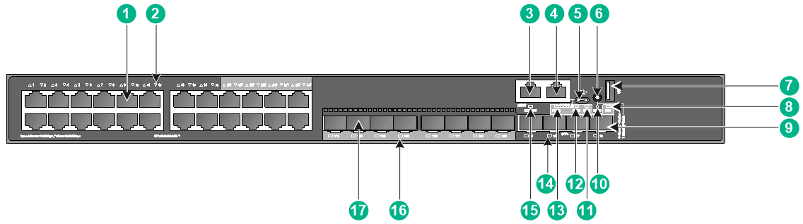
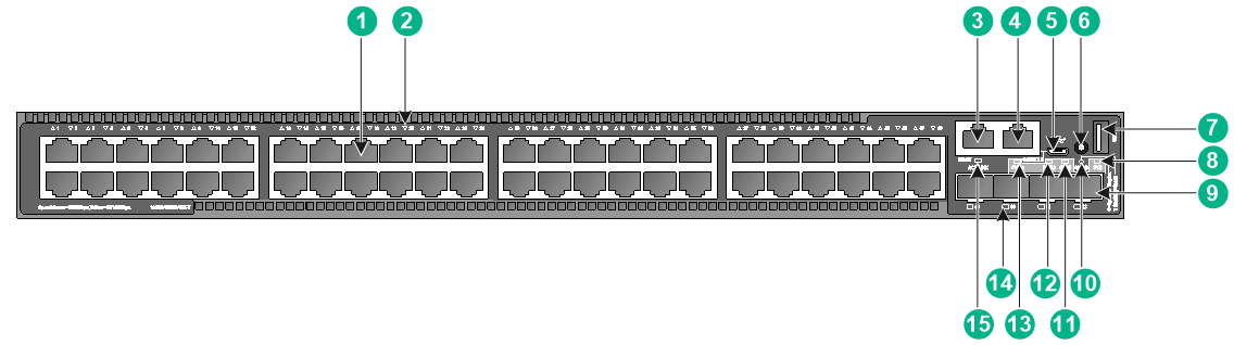
S5560X-30C-EI
Figure2-1 Front panel
|
(1) 10/100/1000BASE-T autosensing Ethernet port |
|
|
(2) 10/100/1000BASE-T autosensing Ethernet port LED |
|
|
(3) Management Ethernet port |
(4) Console port (CONSOLE) |
|
(5) Micro USB console port |
(6) Mode button |
|
(7) USB port |
(8) System status LED (SYS) |
|
(9) SFP+ port |
(10) Mode LED (MODE) |
|
(11) Expansion card status LED (SLOT) |
(12) Power module 2 status LED (PWR2) |
|
(13) Power module 1 status LED (PWR1) |
(14) SFP+ port LED |
|
(15) Management Ethernet port LED (ACT/LINK) |
(16) SFP port LED |
|
(17) SFP port |
|
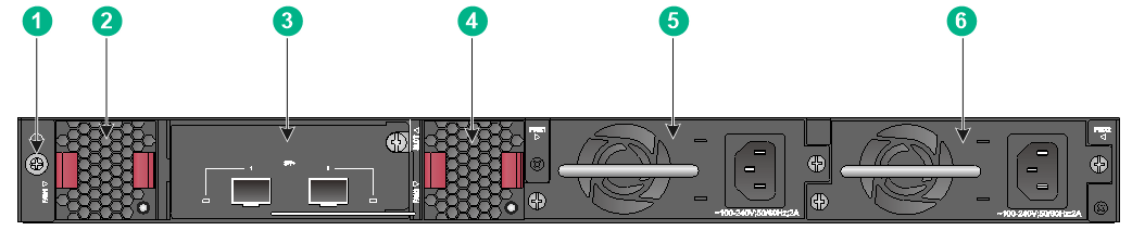
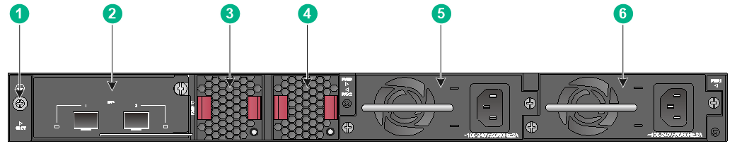
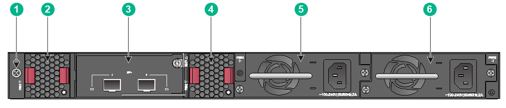
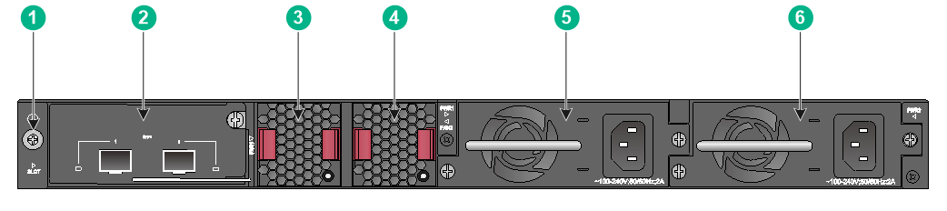
Figure2-2 Rear panel
|
(1) Grounding screw |
(2) Fan tray 1 |
|
(3) Expansion card |
(4) Fan tray 2 |
|
(5) Power module 1 |
(6) Power module 2 |
The S5560X-30C-EI switch comes with power module slot 1 empty and power module slot 2 installed with a filler panel. You can install one or two power modules for the switch as required. In this figure, two PSR150-A1 AC power modules are installed in the power module slots.
The S5560X-30C-EI switch comes with the two fan tray slots empty. You must install two fan trays of the same model for the switch. In this figure, two LSPM1FANSB fan trays are installed in the fan tray slots.
The S5560X-30C-EI switch comes with a filler panel in the expansion slot. You can select an expansion card for the switch as required. In this figure, an LSWM2SP2PM interface card is installed in the expansion slot.
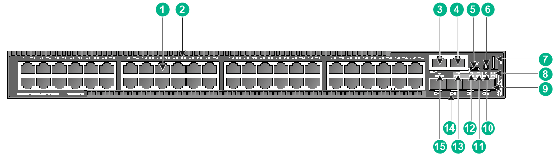
S5560X-30C-PWR-EI
Figure2-3 Front panel
|
(1) 10/100/1000BASE-T autosensing Ethernet port |
|
|
(2) 10/100/1000BASE-T autosensing Ethernet port LED |
|
|
(3) Management Ethernet port |
(4) Console port (CONSOLE) |
|
(5) Micro USB console port |
(6) Mode button |
|
(7) USB port |
(8) System status LED (SYS) |
|
(9) SFP+ port |
(10) Mode LED (MODE) |
|
(11) Expansion card status LED (SLOT) |
(12) Power module 2 status LED (PWR2) |
|
(13) Power module 1 status LED (PWR1) |
(14) SFP+ port LED |
|
(15) Management Ethernet port LED (ACT/LINK) |
|
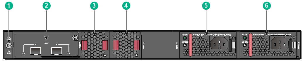
Figure2-4 Rear panel
|
(1) Grounding screw |
(2) Fan tray 1 |
|
(3) Expansion card |
(4) Fan tray 2 |
|
(5) Power module 1 |
(6) Power module 2 |
The S5560X-30C-PWR-EI switch comes with power module slot 1 empty and power module slot 2 installed with a filler panel. You can install one or two power modules for the switch as required. In this figure, two PSR720-56A AC power modules are installed in the power module slots.
The S5560X-30C-PWR-EI switch comes with the two fan tray slots empty. You must install two fan trays of the same model for the switch. In this figure, two LSPM1FANSB fan trays are installed in the fan tray slots.
The S5560X-30C-PWR-EI switch comes with a filler panel in the expansion slot. You can select an expansion card for the switch as required. In this figure, an LSWM2SP2PM interface card is installed in the expansion slot.
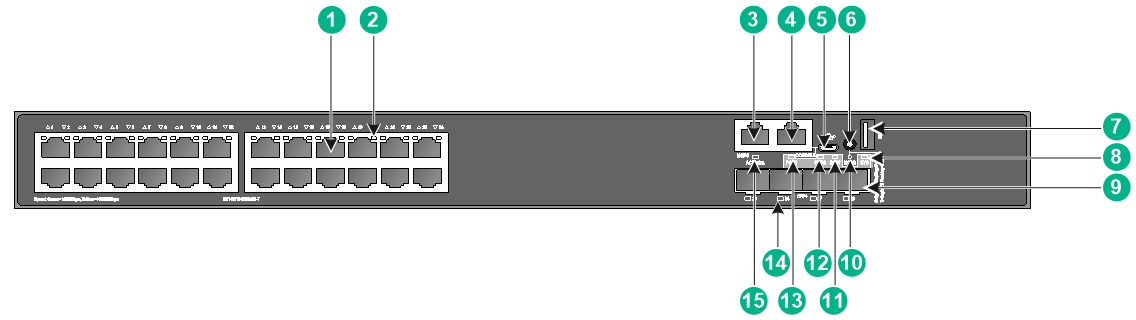
S5560X-54C-EI
Figure2-5 Front panel
|
(1) 10/100/1000BASE-T autosensing Ethernet port |
|
|
(2) 10/100/1000BASE-T autosensing Ethernet port LED |
|
|
(3) Management Ethernet port |
(4) Console port (CONSOLE) |
|
(5) Micro USB console port |
(6) Mode button |
|
(7) USB port |
(8) System status LED (SYS) |
|
(9) SFP+ port |
(10) Mode LED (MODE) |
|
(11) Expansion card status LED (SLOT) |
(12) Power module 2 status LED (PWR2) |
|
(13) Power module 1 status LED (PWR1) |
(14) SFP+ port LED |
|
(15) Management Ethernet port LED (ACT/LINK) |
|
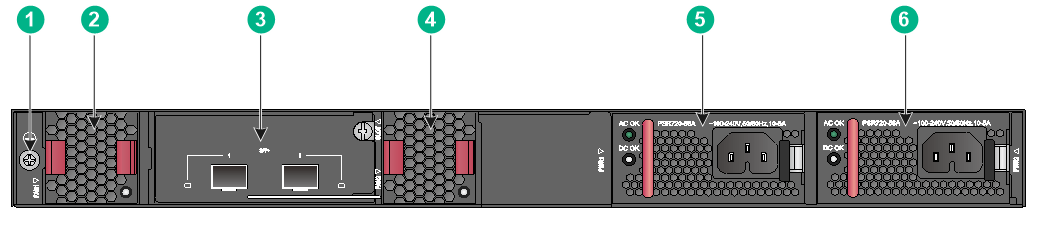
Figure2-6 Rear panel
|
(1) Grounding screw |
(2) Expansion card |
|
(3) Fan tray 1 |
(4) Fan tray 2 |
|
(5) Power module 1 |
(6) Power module 2 |
The S5560X-54C-EI switch comes with power module slot 1 empty and power module slot 2 installed with a filler panel. You can install one or two power modules for the switch as required. In this figure, two PSR150-A1 AC power modules are installed in the power module slots.
The S5560X-54C-EI switch comes with the two fan tray slots empty. You must install two fan trays of the same model for the switch. In this figure, two LSPM1FANSB fan trays are installed in the fan tray slots.
The S5560X-54C-EI switch comes with a filler panel in the expansion slot. You can select an expansion card for the switch as required. In this figure, an LSWM2SP2PM interface card is installed in the expansion slot.
S5560X-54C-PWR-EI
Figure2-7 S5560X-54C-PWR-EI front panel
|
(1) 10/100/1000BASE-T autosensing Ethernet port |
|
|
(2) 10/100/1000BASE-T autosensing Ethernet port LED |
|
|
(3) Management Ethernet port |
(4) Console port (CONSOLE) |
|
(5) Micro USB console port |
(6) Mode button |
|
(7) USB port |
(8) System status LED (SYS) |
|
(9) SFP+ port |
(10) Mode LED (MODE) |
|
(11) Expansion card status LED (SLOT) |
(12) Power module 2 status LED (PWR2) |
|
(13) Power module 1 status LED (PWR1) |
(14) SFP+ port LED |
|
(15) Management Ethernet port LED (ACT/LINK) |
|
Figure2-8 Rear panel
|
(1) Grounding screw |
(2) Expansion card |
|
(3) Fan tray 1 |
(4) Fan tray 2 |
|
(5) Power module 1 |
(6) Power module 2 |
The S5560X-54C-PWR-EI switch comes with power module slot 1 empty and power module slot 2 installed with a filler panel. You can install one or two power modules for the switch as required. In this figure, two PSR720-56A AC power modules are installed in the power module slots.
The S5560X-54C-PWR-EI switch comes with the two fan tray slots empty. You must install two fan trays of the same model for the switch. In this figure, two LSPM1FANSB fan trays are installed in the fan tray slots.
The S5560X-54C-PWR-EI switch comes with a filler panel in the expansion slot. You can select an expansion card for the switch as required. In this figure, an LSWM2SP2PM interface card is installed in the expansion slot.
S5560X-30F-EI
Figure2-9 Front panel

|
(1) SFP port |
(2) SFP port LED |
|
(3) 10/100/1000BASE-T autosensing Ethernet port |
|
|
(4) 10/100/1000BASE-T autosensing Ethernet port LED |
|
|
(5) Management Ethernet port |
(6) Console port (CONSOLE) |
|
(7) Micro USB console port |
(8) Mode button |
|
(9) USB port |
(10) System status LED (SYS) |
|
(11) SFP+ port |
(12) Mode LED (MODE) |
|
(13) Expansion card status LED (SLOT) |
(14) Power module 2 status LED (PWR2) |
|
(15) Power module 1 status LED (PWR1) |
(16) SFP+ port LED |
|
(17) Management Ethernet port LED (ACT/LINK) |
|
Figure2-10 Rear panel
|
(1) Grounding screw |
(2) Fan tray 1 |
|
(3) Expansion card |
(4) Fan tray 2 |
|
(5) Power module 1 |
(6) Power module 2 |
The S5560X-30F-EI switch comes with power module slot 1 empty and power module slot 2 installed with a filler panel. You can install one or two power modules for the switch as required. In this figure, two PSR150-A1 AC power modules are installed in the power module slots.
The S5560X-30F-EI switch comes with the two fan tray slots empty. You must install two fan trays of the same model for the switch. In this figure, two LSPM1FANSB fan trays are installed in the fan tray slots.
The S5560X-30F-EI switch comes with a filler panel in the expansion slot. You can select an expansion card for the switch as required. In this figure, an LSWM2SP2PM interface card is installed in the expansion slot.
S5560X-30F-EIF
Figure2-11 Front panel
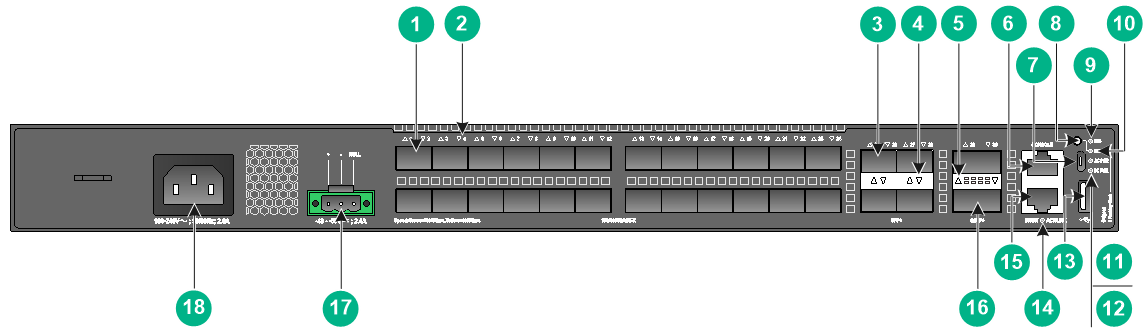
|
(1) SFP port |
(2) SFP port LED |
|
(3) SFP+ port |
(4) SFP+ port LED |
|
(5) QSFP+ port LED |
(6) Console port (CONSOLE) |
|
(7) Micro USB console port |
(8) Mode button |
|
(9) System status LED (SYS) |
(10) Mode LED (MODE) |
|
(11) AC power input status LED (AC PWR) |
(12) DC power input status LED (DC PWR) |
|
(13) USB port |
(14) Management Ethernet port LED (ACT/LINK) |
|
(15) Management Ethernet port |
(16) QSFP+ port |
|
(17) DC-input power receptacle |
(18) AC-input power receptacle |
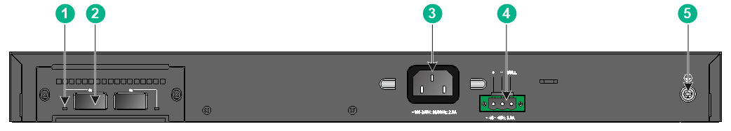
Figure2-12 Rear panel
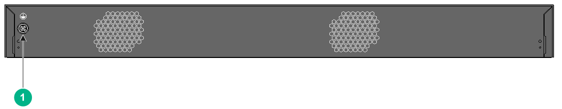
|
(1) Grounding screw |
S5560X-54F-EI
Figure2-13 Front panel
|
(1) SFP port |
(2) SFP port LED |
|
(3) Management Ethernet port |
(4) Console port (CONSOLE) |
|
(5) Micro USB console port |
(6) Mode button |
|
(7) USB port |
(8) System status LED (SYS) |
|
(9) SFP+ port |
(10) Mode LED (MODE) |
|
(11) Expansion card status LED (SLOT) |
(12) Power module 2 status LED (PWR2) |
|
(13) Power module 1 status LED (PWR1) |
(14) SFP+ port LED |
|
(15) Management Ethernet port LED (ACT/LINK) |
|
Figure2-14 Rear panel
|
(1) Grounding screw |
(2) Expansion card |
|
(3) Fan tray 1 |
(4) Fan tray 2 |
|
(5) Power module 1 |
(6) Power module 2 |
The S5560X-54F-EI switch comes with power module slot 1 empty and power module slot 2 installed with a filler panel. You can install one or two power modules for the switch as required. In this figure, two PSR150-A1 AC power modules are installed in the power module slots.
The S5560X-54F-EI switch comes with the two fan tray slots empty. You must install two fan trays of the same model for the switch. In this figure, two LSPM1FANSB fan trays are installed in the fan tray slots.
The S5560X-54F-EI switch comes with a filler panel in the expansion slot. You can select an expansion card for the switch as required. In this figure, an LSWM2SP2PM interface card is installed in the expansion slot.
S5560X-34S-EI
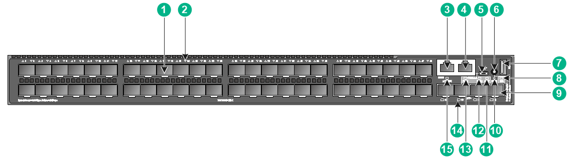
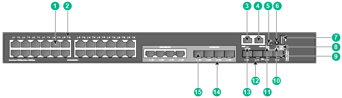
Figure2-15 Front panel
|
(1) 10/100/1000BASE-T autosensing Ethernet port |
|
|
(2) 10/100/1000BASE-T autosensing Ethernet port LED |
|
|
(3) Management Ethernet port |
(4) Console port (CONSOLE) |
|
(5) Micro USB console port |
(6) Mode button |
|
(7) USB port |
(8) System status LED (SYS) |
|
(9) SFP+ port |
(10) Mode LED (MODE) |
|
(11) RPS status LED (RPS) |
(12) SFP+ port LED |
|
(13) Management Ethernet port LED (ACT/LINK) |
(14) SFP port LED |
|
(15) SFP port |
|
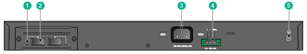
Figure2-16 Rear panel
|
(1) QSFP+ port LED |
(2) QSFP+ port |
|
(3) AC power receptacle |
(4) DC power receptacle |
|
(5) Grounding screw |
|
S5560X-54S-EI
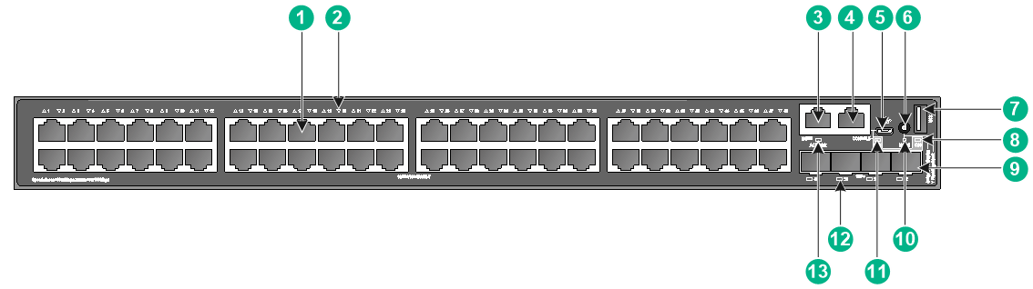
Figure2-17 Front panel
|
(1) 10/100/1000BASE-T autosensing Ethernet port |
|
|
(2) 10/100/1000BASE-T autosensing Ethernet port LED |
|
|
(3) Management Ethernet port |
(4) Console port (CONSOLE) |
|
(5) Micro USB console port |
(6) Mode button |
|
(7) USB port |
(8) System status LED (SYS) |
|
(9) SFP+ port |
(10) Mode LED (MODE) |
|
(11) RPS status LED (RPS) |
(12) SFP+ port LED |
|
(13) Management Ethernet port LED (ACT/LINK) |
|
Figure2-18 Rear panel
|
(1) QSFP+ port LED |
(2) QSFP+ port |
|
(3) AC power receptacle |
(4) DC power receptacle |
|
(5) Grounding screw |
|
3 FRUs and compatibility matrixes
S5560X-EI switches except the S5560X-30F-EIF, S5560X-34S-EI, and S5560X-54S-EI use modular design and support FRUs.
Table3-1 FRUs and compatibility matrixes
|
FRUs |
S5560X-30C-EI S5560X-54C-EI S5560X-30F-EI S5560X-54F-EI |
S5560X-30C-PWR-EI S5560X-54C-PWR-EI |
|
Removable power modules |
||
|
PSR150-A1 |
Supported |
Not supported |
|
PSR150-A2 |
Supported |
Not supported |
|
PSR150-D1 |
Supported |
Not supported |
|
PSR360-56A |
Not supported |
Supported |
|
PSR560-56D |
Not supported |
Supported |
|
PSR720-56A |
Not supported |
Supported |
|
PSR1110-56A |
Not supported |
Supported |
|
Removable fan trays |
||
|
LSPM1FANSA |
Supported |
Supported |
|
LSPM1FANSB |
Supported |
Supported |
|
Expansion cards |
||
|
LSWM2QP2P |
Supported |
Supported |
|
LSWM2SP2PM |
Supported |
Supported |
|
LSWM4SP8PM |
Supported |
Supported |
|
LSWM2XGT2PM |
Supported |
Supported |
|
LSWM2SP8P |
Supported |
Supported |
|
LSPM4G4T6P |
Supported |
Supported |
|
LSPM6FWD |
Supported |
Supported |
|
LSPM6FWD8 |
Supported |
Supported |
|
LSWM2XMGT8P |
Supported |
Supported |
|
LSWM2MGT8P |
Supported |
Supported |
|
LSWM2ZSP2P |
Supported |
Supported |
|
LSWM2SP2PB |
Supported |
Supported |
|
LSWM2SP4PB |
Supported |
Supported |
The power modules support asset management. You can use the display device manuinfo command to view the name, sequence number, and vendor of the power modules you have installed on the device.
You can install one power module, or two power modules for redundancy on the S5560X-30C-EI, S5560X-54C-EI, S5560X-30F-EI, and S5560X-54F-EI switches. These switches support mix of an AC power module and a DC power module.
You can install one power module, or two power modules for redundancy on the S5560X-30C-PWR-EI and S5560X-54C-PWR-EI switches. The PoE capabilities of these switches vary by power module configuration. For more information, see Table1-3.
S5560X-EI switches except the S5560X-30F-EIF, S5560X-34S-EI, and S5560X-54S-EI use removable fan trays. Do not power on the switch if it does not have two fan trays of the same model installed.
Removable power modules
S5560X-EI switches except the S5560X-30F-EIF, S5560X-34S-EI, and S5560X-54S-EI provide power module slots and use removable power modules. Select power modules for the switches as required.
Table3-2 Removable power modules
|
Power module |
Specifications |
Reference |
|
PSR150-A1 |
· Rated input voltage range: 100 VAC to 240 VAC @ 50 Hz or 60 Hz · Max input voltage range: 90 VAC to 264 VAC @ 47 Hz to 63 Hz · Max output power: 150 W |
H3C PSR150-A & PSR150-D Series Power Modules User Manual |
|
PSR150-A2 |
· Rated input voltage range: 100 VAC to 240 VAC @ 50 Hz or 60 Hz · Max input voltage range: 90 VAC to 264 VAC @ 47 Hz to 63 Hz · Max output power: 150 W |
|
|
PSR150-D1 |
· Rated input voltage range: –48 VDC to –60 VDC · Max input voltage range: –36 VDC to –72 VDC · Max output power: 150 W |
|
|
PSR360-56A |
· Rated input voltage range: 100 VAC to 240 VAC @ 50 Hz or 60 Hz · Max input voltage range: 90 VAC to 264 VAC @ 47 Hz to 63 Hz · Max output power: 360 W |
H3C PSR360-56A Power Module User Manual |
|
PSR560-56D |
· Rated input voltage range: –48 VDC to –60 VDC · Max input voltage range: –36 VDC to –72 VDC · Max output power: 560 W |
H3C PSR560-56D Power Module User Manual |
|
PSR720-56A |
· Rated input voltage range: 100 VAC to 240 VAC @ 50 Hz or 60 Hz · Max input voltage range: 90 VAC to 264 VAC @ 47 Hz to 63 Hz · Max output power: 720 W |
H3C PSR720-56A Power Module User Manual |
|
PSR1110-56A |
· Rated input voltage range: 115 VAC to 240 VAC @ 50 Hz or 60 Hz · Max input voltage range: 102.5 VAC to 264 VAC @ 47 Hz to 63 Hz · Max output power: 1110 W |
H3C PSR1110-56A Power Module User Manual |
|
|
NOTE: The PSR1110-56A power module adds 64 mm (2.52 in) to the total depth of the switch, which includes the power module handle. |
Removable fan trays
S5560X-EI switches except the S5560X-30F-EIF, S5560X-34S-EI, and S5560X-54S-EI support the LSPM1FANSA and LSPM1FANSB fan trays.
Table3-3 Removable fan trays
|
Item |
Specifications |
|
LSPM1FANSA fan tray |
|
|
Dimensions |
40 × 40 × 104 mm (1.57 × 1.57 × 4.09 in) |
|
Fan speed |
20000 R.P.M |
|
Max airflow |
20 CFM |
|
Airflow direction |
Back to front (from the power module side to the network port side) |
|
Input voltage |
12 V |
|
Maximum power consumption |
9.8 W |
|
Reference |
H3C LSPM1FANSA & LSPM1FANSB Fan Trays User Guide |
|
LSPM1FANSB fan tray |
|
|
Dimensions |
40 × 40 × 104 mm (1.57 × 1.57 × 4.09 in) |
|
Fan speed |
20000 R.P.M |
|
Max airflow |
20 CFM |
|
Airflow direction |
Front to back (from the network port side to the power module side) |
|
Input voltage |
12 V |
|
Maximum power consumption |
9.8 W |
|
Reference |
H3C LSPM1FANSA & LSPM1FANSB Fan Trays User Guide |
Expansion cards
S5560X-EI switches except the S5560X-30F-EIF, S5560X-34S-EI, and S5560X-54S-EI each provide an expansion slot at the rear. Select expansion cards for the switches as required.
Table3-4 Expansion cards
|
Item |
Specifications |
|
LSWM2QP2P |
|
|
Description |
2-port 40GE QSFP+ interface card |
|
Port type and quantity |
2 × 40 Gbps QSFP+ fiber ports |
|
Available transceiver modules and cables |
|
|
Reference |
H3C LSWM2QP2P Interface Card User Manual |
|
LSWM4SP8PM and LSWM2SP8P |
|
|
Description |
8-port 10GE SFP+ interface card |
|
Port type and quantity |
8 × 10 Gbps SFP+ fiber ports |
|
Available transceiver modules and cables |
|
|
Reference |
H3C LSWM4SP8PM Interface Card User Manual and H3C LSWM2SP8PM & LSWM2SP8P Interface Cards User Manual |
|
LSWM2SP2PM |
|
|
Description |
2-port 10GE SFP+ interface card |
|
Port type and quantity |
2 × 1/10 Gbps SFP+ fiber ports |
|
Available transceiver modules and cables |
|
|
Reference |
H3C LSWM2SP2PM Interface Card User Manual |
|
LSWM2XGT2PM |
|
|
Description |
2-port 1/10GBASE-T interface card |
|
Port type and quantity |
2 × 1/10GBASE-T Ethernet ports |
|
Available cables |
See Table4-3. |
|
Reference |
H3C LSWM2XGT2PM & LSWM2XGT8PM Interface Cards User Manual |
|
LSPM4G4T6P |
|
|
Description |
4-port 10/100/1000BASE-T + 6-port SFP interface card |
|
Port type and quantity |
· 4 ×10/100/1000BASE-T autosensing Ethernet ports · 6 × SFP fiber ports SFP ports 5S and 6S form combo interfaces with 10/100/1000BASE-T autosensing Ethernet ports 5T and 6T, respectively. |
|
Available transceiver modules and cables |
SFP ports 5S and 6S support FE SFP modules in Table4-7 and GE SFP modules and cables in Table4-8. The other SFP ports support GE SFP modules and cables in Table4-8. |
|
Reference |
H3C LSPM4G4T6P Interface Card User Manual |
|
LSPM6FWD |
|
|
Description |
The card is a fourth-generation high performance firewall card. It provides features including firewall, VPN, content filtering, content identification, URL filtering, and NAT. By using this card on a switch, you can enhance the switch security capabilities without changing the network topology. |
|
Reference |
H3C LSPM6FWD Card Manual |
|
LSPM6FWD8 |
|
|
Description |
The card is a fourth-generation high performance firewall card. It provides features including firewall, VPN, content filtering, content identification, URL filtering, and NAT. By using this card on a switch, you can enhance the switch security capabilities without changing the network topology. |
|
Reference |
H3C LSPM6FWD8 Card Manual |
|
LSWM2XMGT8P |
|
|
Description |
8-port 1/2.5/5/10GBASE-T interface card |
|
Port type and quantity |
8 × 10G/5G/2.5G/1000BASE-T autosensing Ethernet ports |
|
Available cables |
See Table4-6. |
|
Reference |
H3C LSWM2MGT8P & LSWM2XMGT8P Interface Cards User Manual |
|
LSWM2MGT8P |
|
|
Description |
8-port 1/2.5/5GBASE-T interface card |
|
Port type and quantity |
8 × 5G/2.5G/1000BASE-T autosensing Ethernet ports |
|
Available cables |
See Table4-5. |
|
Reference |
H3C LSWM2MGT8P & LSWM2XMGT8P Interface Cards User Manual |
|
LSWM2ZSP2P |
|
|
Description |
2-port 25G SFP28 interface card |
|
Port type and quantity |
2 × SFP28 ports |
|
Available transceiver modules and cables |
|
|
Reference |
H3C LSWM2ZSP2P Interface Card User Manual |
|
LSWM2SP2PB |
|
|
Description |
2-port 10GE SFP+ interface card |
|
Port type and quantity |
2 × 1/10GE SFP+ ports |
|
Available transceiver modules and cables |
|
|
Reference |
H3C LSWM2SP2PB & LSWM2SP4PB Interface Cards User Manual |
|
LSWM2SP4PB |
|
|
Description |
4-port 10GE SFP+ interface card |
|
Port type and quantity |
4 × 1/10GE SFP+ ports |
|
Available transceiver modules and cables |
|
|
Reference |
H3C LSWM2SP2PB & LSWM2SP4PB Interface Cards User Manual |
For more information about these expansion cards, see user manuals for the expansion cards.
|
|
NOTE: · The ports on an LSWM2SP2PM or LSWM2XGT2PM interface card can operate only at 10 Gbps when the interface card is installed on the device. · An LSPM6FWD or LSPM6FWD8 firewall card (including its handle) adds 75 mm (2.95 in) to the chassis depth when installed on the device. |
Connecting cables to the copper ports on the interface cards
The LSWM2XGT2PM interface card provides copper ports. To connect cables to the copper ports on the LSWM2XGT2PM interface card, follow these guidelines:
· Use Category-6A or above cables and connectors. The max transmission distance varies by cable type:
¡ Category-6 UTP—55 m (180.45 ft).
¡ Category-6 STP—100 m (328.084 ft), no interference.
¡ Category-6 SFTP—100 m (328.084 ft).
¡ Category-6A and above twisted pair—100 m (328.084 ft).
· Do not bundle cables in their first 20 m (65.62 ft).
· Separate power cords and twisted pair cables at and around the distribution frame.
· For ports adjacent to one another on the device, the peer ports on the distribution frame is preferably not adjacent, for example:
¡ If the device connects to one distribution frame, connect port 1 on the device to port 1 on the distribution frame and port 2 on the device to port 3 on the distribution frame.
¡ If the device connects to two distribution frames, connect port 1 on the device to port 1 on distribution frame 1 and port 2 on the device to port 1 on distribution frame 2.
· Keep the device and twisted pair cables away from the interference source, such as a two-way radio and a high-power variable-frequency drive.
4 Ports and LEDs
Ports
Console port
The switch has two console ports: a serial console port and a micro USB console port.
Table4-1 Console port specifications
|
Item |
Serial console port |
Micro USB console port |
|
Connector type |
RJ-45 |
Micro USB Type B |
|
Compliant standard |
EIA/TIA-232 |
USB 2.0 |
|
Transmission baud rate |
9600 bps (default) to 115200 bps |
|
|
Services |
· Provides connection to an ASCII terminal. · Provides connection to the serial port of a local PC running terminal emulation program. |
Provides connection to the USB port of a local PC running terminal emulation program. |
Management Ethernet port
The switch provides a management Ethernet port on the front panel. You can connect this port to a PC or management station for loading and debugging software or remote management.
Table4-2 Management Ethernet port specifications
|
Item |
Specification |
|
Connector type |
RJ-45 |
|
Connector quantity |
1 |
|
Port transmission rate |
10/100/1000 Mbps, half/full duplex |
|
Transmission medium and max transmission distance |
100 m (328.08 ft) over category-5 twisted pair cable |
|
Functions and services |
Switch software and Boot ROM upgrade, network management |
USB port
The switch has one OHC-compliant USB2.0 port that can upload and download data at a rate up to 480 Mbps. You can use this USB port to access the file system on the flash of the switch, for example, to upload or download application and configuration files.
|
|
NOTE: USB devices from different vendors vary in compatibilities and drivers. H3C does not guarantee the correct operation of USB devices from all vendors on the switch. If a USB device fails to operate on the switch, replace it with one from another vendor. |
1/10BASE-T autosensing Ethernet port
The LSWM2XGT2PM interface card provides 1/10BASE-T autosensing Ethernet ports.
Table4-3 1/10BASE-T autosensing Ethernet port specifications
|
Item |
Specification |
|
Connector type |
RJ-45 |
|
Interface attributes |
1/10 Gbps, full duplex, MDI/MDI-X auto-sensing |
|
Max transmission distance |
· Category-6 UTP—55 m (180.45 ft) · Category-6 STP—100 m (328.08 ft) · Category-6 SFTP—100 m (328.08 ft) · Category-6 and above twisted pair—100 m (328.08 ft) |
|
Transmission medium |
Category-6 (or above) twisted pair cable |
|
Standards |
IEEE 802.3an, 802.3ab |
10/100/1000BASE-T autosensing Ethernet port
All the S5560X-EI switch models, except the S5560X-54F-EI and S5560X-30F-EIF switches, provide 10/100/1000BASE-T autosensing Ethernet ports.
Table4-4 10/100/1000BASE-T autosensing Ethernet port specifications
|
Item |
Specification |
|
Connector type |
RJ-45 |
|
Interface attributes |
· 10 Mbps, half/full duplex · 100 Mbps, half/full duplex · 1000 Mbps, full duplex · MDI/MDI-X, auto-sensing |
|
Max transmission distance |
100 m (328.08 ft) |
|
Transmission medium |
Category-5 (or above) twisted pair cable |
|
Standards |
IEEE 802.3i, 802.3u, 802.3ab |
5G/2.5G/1000BASE-T autosensing Ethernet port
The LSWM2MGT8P interface card provides 5G/2.5G/1000BASE-T autosensing Ethernet ports.
Table4-5 5G/2.5G/1000BASE-T autosensing Ethernet port specifications
|
Item |
Specification |
|
Connector type |
RJ-45 |
|
Port speed, duplex mode, MDIX mode |
1/2.5/5 Gbps, full duplex, auto-MDI/MDIX |
|
Transmission medium and max transmission distance |
· 5G mode: 100 m (328.08 ft) over a Category-5e or above twisted pair cable. · 2.5G mode: 200 m (656.17 ft) over a Category-5e or above twisted pair cable. · 1G mode: 140 m (459.32 ft) over a Category-5e or above twisted pair cable. |
|
Standards |
IEEE 802.3ab, 802.3an |
10G/5G/2.5G/1000BASE-T autosensing Ethernet port
The LSWM2XMGT8P interface card provides 10G/5G/2.5G/1000BASE-T autosensing Ethernet ports.
Table4-6 10G/5G/2.5G/1000BASE-T autosensing Ethernet port specifications
|
Item |
Specification |
|
Connector type |
RJ-45 |
|
Speed, duplex mode, and MDIX mode |
1/2.5/5/10 Gbps, full duplex, auto-MDI/MDIX |
|
Transmission medium and max transmission distance |
· 10G mode: ¡ 100 m (328.08 ft) over a Category-6 or above shielded twisted pair (STP) cable. ¡ 55 m (180.45 ft) over a Category-5e twisted pair or Category-6 unshielded twisted pair (UTP) cable. · 5G mode: 100 m (328.08 ft) over a Category-5e or above twisted pair cable. · 2.5G mode: 200 m (656.17 ft) over a Category-5e or above twisted pair cable. · 1G mode: 140 m (459.32 ft) over a Category-5e or above twisted pair cable. |
|
Standards |
IEEE 802.3ab, 802.3an |
SFP port
The S5560X-30C-EI, S5560X-30F-EI, S5560X-30F-EIF, S5560X-54F-EI, and S5560X-34S-EI switches provide 8, 24, 24, 48, and 4 fixed SFP ports on the front panel, respectively.
You can install the FE SFP modules in Table4-7 and GE SFP transceiver modules and cables in Table4-8 in the SFP ports.
Table4-7 FE SFP transceiver modules available for the SFP ports
|
FE SFP module |
Central wavelength (nm) |
Connector |
Fiber diameter (µm) |
Max transmission distance |
|
SFP-FE-SX-MM1310-A |
1310 |
LC |
Multi-mode, 50/125 |
2 km (1.24 miles) |
|
Multi-mode, 62.5/125 |
||||
|
SFP-FE-LX-SM1310-A |
1310 |
LC |
Single-mode, 9/125 |
15 km (9.32 miles) |
|
SFP-FE-LX-SM1310-D |
1310 |
LC |
Single-mode, 9/125 |
15 km (9.32 miles) |
|
SFP-FE-LH40-SM1310 |
1310 |
LC |
Single-mode, 9/125 |
40 km (24.86 miles) |
|
SFP-FE-LH80-SM1550 |
1550 |
LC |
Single-mode, 9/125 |
80 km (49.71 miles) |
|
SFP-FE-LX-SM1310-BIDI |
· TX: 1310 · RX: 1550 |
LC |
Single-mode, 9/125 |
15 km (9.32 miles) |
|
SFP-FE-LX-SM1550-BIDI |
· TX: 1550 · RX: 1310 |
|
|
IMPORTANT: The SFP-FE-LX-SM1310-BIDI and SFP-FE-LX-SM1550-BIDI modules must be used in pairs. |
Table4-8 GE SFP transceiver modules and cables available for the SFP ports
|
GE SFP transceiver module and cable |
Central wavelength (nm) |
Connector |
Cable/Fiber type and diameter (µm) |
Modal bandwidth (MHz × km) |
Max transmission distance |
|
SFP copper transceiver module |
|||||
|
SFP-GE-T |
N/A |
RJ-45 |
Twisted pair cable |
N/A |
100 m (328.08 ft) |
|
SFP-GE-T-D |
N/A |
RJ-45 |
Twisted pair cable |
N/A |
100 m (328.08 ft) |
|
SFP fiber transceiver module |
|||||
|
SFP-GE-SX-MM850-A |
850 |
LC |
Multi-mode, 50/125 |
500 |
550 m (1804.46 ft) |
|
400 |
500 m (1640.42 ft) |
||||
|
Multi-mode, 62.5/125 |
200 |
275 m (902.23 ft) |
|||
|
160 |
220 m (721.78 ft) |
||||
|
SFP-GE-SX-MM850-D |
850 |
LC |
Multi-mode, 50/125 |
500 |
550 m (1804.46 ft) |
|
400 |
500 m (1640.42 ft) |
||||
|
Multi-mode, 62.5/125 |
200 |
275 m (902.23 ft) |
|||
|
160 |
220 m (721.78 ft) |
||||
|
SFP-GE-SX-MM850-S |
850 |
LC |
Multi-mode, 50/125 |
500 |
550 m (1804.46 ft) |
|
400 |
500 m (1640.42 ft) |
||||
|
Multi-mode, 62.5/125 |
200 |
275 m (902.23 ft) |
|||
|
160 |
220 m (721.78 ft) |
||||
|
SFP-GE-LX-SM1310-A |
1310 |
LC |
Single-mode, 9/125 |
N/A |
10 km (6.21 miles) |
|
Multi-mode, 50/125 |
500 or 400 |
550 m (1804.46 ft) |
|||
|
Multi-mode, 62.5/125 |
500 |
550 m (1804.46 ft) |
|||
|
SFP-GE-LX-SM1310-D |
1310 |
LC |
Single-mode, 9/125 |
N/A |
10 km (6.21 miles) |
|
SFP-GE-LX-SM1310-S |
1310 |
LC |
Single-mode, 9/125 |
N/A |
10 km (6.21 miles) |
|
SFP-GE-LH40-SM1310 |
1310 |
LC |
Single-mode, 9/125 |
N/A |
40 km (24.86 miles) |
|
SFP-GE-LH40-SM1310 |
1310 |
LC |
Single-mode, 9/125 |
N/A |
40 km (24.86 miles) |
|
SFP-GE-LH40-SM1550 |
1550 |
LC |
Single-mode, 9/125 |
N/A |
40 km (24.86 miles) |
|
SFP-GE-LH80-SM1550 |
1550 |
LC |
Single-mode, 9/125 |
N/A |
80 km (49.71 miles) |
|
SFP-GE-LH80-SM1550-D |
1550 |
LC |
Single-mode, 9/125 |
N/A |
80 km (49.71 miles) |
|
SFP-GE-LH100-SM1550 |
1550 |
LC |
Single-mode, 9/125 |
N/A |
100 km (62.14 miles) |
|
SFP-GE-LX-SM1310-BIDI |
TX: 1310 RX: 1490 |
LC |
Single-mode, 9/125 |
N/A |
10 km (6.21 miles) |
|
SFP-GE-LX-SM1490-BIDI |
TX: 1490 RX: 1310 |
LC |
Single-mode, 9/125 |
N/A |
10 km (6.21 miles) |
|
SFP-GE-LH40-SM1310-BIDI |
TX: 1310 RX: 1550 |
LC |
Single-mode, 9/125 |
N/A |
40 km (24.86 miles) |
|
SFP-GE-LH40-SM1550-BIDI |
TX: 1550 RX: 1310 |
LC |
Single-mode, 9/125 |
N/A |
40 km (24.86 miles) |
|
SFP-GE-LH70-SM1490-BIDI |
TX: 1490 RX: 1550 |
LC |
Single-mode, 9/125 |
N/A |
70 km (43.50 miles) |
|
SFP-GE-LH70-SM1550-BIDI |
TX: 1550 RX: 1490 |
LC |
Single-mode, 9/125 |
N/A |
70 km (43.50 miles) |
|
SFP cable |
|||||
|
SFP-STACK-Kit |
N/A |
1.5 m (4.92 ft) |
|||
|
IMPORTANT: · The SFP-GE-LX-SM1310-BIDI and SFP-GE-LX-SM1490-BIDI transceiver modules, the SFP-GE-LH40-SM1310-BIDI and SFP-GE-LH40-SM1550-BIDI transceiver modules, and the SFP-GE-LH70-SM1490-BIDI and SFP-GE-LH70-SM1550-BIDI transceiver modules must be used in pairs. For example, if one end uses an SFP-GE-LX-SM1310-BIDI transceiver module, the other end must uses an SFP-GE-LX-SM1490-BIDI transceiver module. · To install multiple SFP-GE-LH100-SM1550 transceiver modules on the S5560X-30C-EI, S5560X-30F-EI, S5560X-30F-EIF, and S5560X-54F-EI switches, separate these transceiver modules by other types of transceiver modules. For example, you can install SFP-GE-LH100-SM1550 transceiver modules in ports 1 and 2, other types of transceiver modules in ports 3 and 4, and SFP-GE-LH100-SM1550 transceiver modules in ports 5 and 6. |
|
|
NOTE: · As a best practice, use H3C transceiver modules and cables for the switch. · The H3C transceiver modules and cables are subject to change over time. For the most recent list of H3C transceiver modules and cables, contact your H3C Support or marketing staff. · For more information about H3C transceiver modules and cables, see H3C Transceiver Modules User Guide. |
SFP+ port
The switch provides four fixed SFP+ ports on the front panel. To connect peer SFP+ ports over a long distance, use SFP/SFP+ transceiver modules and fibers. To connect peer SFP+ ports over a short distance, use SFP/SFP+ cables. You can install the GE SFP transceiver module and cables in Table4-8, 10-GE SFP+ transceiver modules in Table4-9, and 10-GE SFP+ cables in Table4-10 in the SFP+ ports.
Table4-9 10-GE SFP+ transceiver modules available for the SFP+ ports
|
10-GE SFP+ transceiver module |
Central wavelength (nm) |
Connector |
Fiber diameter (µm) |
Multimode fiber modal bandwidth (MHz × km) |
Max transmission distance |
|
SFP-XG-SX-MM850-D |
850 |
LC |
Multi-mode, 50/125 |
2000 |
300 m (984.25 ft) |
|
500 |
82 m (269.03 ft) |
||||
|
400 |
66 m (216.54 ft) |
||||
|
Multi-mode, 62.5/125 |
200 |
33 m (108.27 ft) |
|||
|
160 |
26 m (85.30 ft) |
||||
|
SFP-XG-SX-MM850-E |
850 |
LC |
Multi-mode, 50/125 |
2000 |
300 m (984.25 ft) |
|
500 |
82 m (269.03 ft) |
||||
|
400 |
66 m (216.54 ft) |
||||
|
Multi-mode, 62.5/125 |
200 |
33 m (108.27 ft) |
|||
|
160 |
26 m (85.30 ft) |
||||
|
SFP-XG-SX-MM850-S |
850 |
LC |
Multi-mode, 50/125 |
2000 |
300 m (984.25 ft) |
|
500 |
82 m (269.03 ft) |
||||
|
400 |
66 m (216.54 ft) |
||||
|
Multi-mode, 62.5/125 |
200 |
33 m (108.27 ft) |
|||
|
160 |
26 m (85.30 ft) |
||||
|
SFP-XG-LX-SM1310-D |
1310 |
LC |
Single-mode, 9/125 |
N/A |
10 km (6.21 miles) |
|
SFP-XG-LX-SM1310-E |
1310 |
LC |
Single-mode, 9/125 |
N/A |
10 km (6.21 miles) |
|
SFP-XG-LX-SM1310-S |
1310 |
LC |
Single-mode, 9/125 |
N/A |
10 km (6.21 miles) |
|
SFP-XG-LH40-SM1550 |
1550 |
LC |
Single-mode, 9/125 |
N/A |
40 km (24.86 miles) |
|
SFP-XG-LH40-SM1550-D |
1550 |
LC |
Single-mode, 9/125 |
N/A |
40 km (24.86 miles) |
|
SFP-XG-LH80-SM1550 |
1550 |
LC |
Single-mode, 9/125 |
N/A |
80 km (49.71 miles) |
|
SFP-XG-LH80-SM1550-D |
1550 |
LC |
Single-mode, 9/125 |
N/A |
80 km (49.71 miles) |
|
SFP-XG-LX-SM1270-BIDI |
TX: 1270 RX: 1330 |
LC |
Single-mode, 9/125 |
N/A |
10 km (6.21 miles) |
|
SFP-XG-LX-SM1330-BIDI |
TX: 1330 RX: 1270 |
LC |
Single-mode, 9/125 |
N/A |
10 km (6.21 miles) |
|
SFP-XG-LH40-SM1270-BIDI |
TX: 1270 RX: 1330 |
LC |
Single-mode, 9/125 |
N/A |
40 km (24.86 miles) |
|
SFP-XG-LH40-SM1330-BIDI |
TX: 1330 RX: 1270 |
LC |
Single-mode, 9/125 |
N/A |
40 km (24.86 miles) |
|
|
IMPORTANT: The SFP-XG-LX-SM1270-BIDI and SFP-XG-LX-SM1330-BIDI transceiver modules and the SFP-XG-LH40-SM1270-BIDI and SFP-XG-LH40-SM1330-BIDI transceiver modules must be used in pairs. For example, if one end uses an SFP-XG-LX-SM1270-BIDI transceiver module, the other end must use an SFP-XG-LX-SM1330-BIDI transceiver module. |
Table4-10 SFP+ copper cables available for the SFP+ ports
|
SFP+ copper cable |
Cable length |
|
LSWM1STK |
0.65 m (2.13 ft) |
|
LSWM2STK |
1.2 m (3.94 ft) |
|
LSWM3STK |
3 m (9.84 ft) |
|
LSTM1STK |
5 m (16.40 ft) |
Table4-11 SFP+ fiber cables available for the SFP+ ports
|
SFP+ fiber cable |
Cable length |
|
SFP-XG-D-AOC-7M |
7 m (22.97 ft) |
|
SFP-XG-D-AOC-10M |
10 m (32.81 ft) |
|
SFP-XG-D-AOC-20M |
20 m (65.62 ft) |
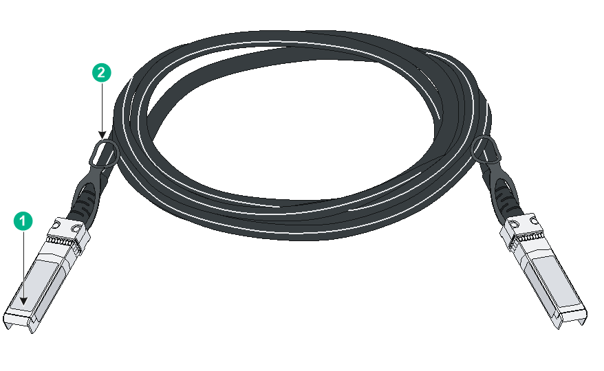
Figure4-1 SFP+ cable
|
(1) Connector |
(2) Pull latch |
|
|
NOTE: · As a best practice, use H3C transceiver modules and cables for the switch. · The H3C transceiver modules and cables are subject to change over time. For the most recent list of H3C transceiver modules and cables, contact your H3C Support or marketing staff. · For more information about H3C transceiver modules and cables, see H3C Transceiver Modules User Guide. |
SFP28 port
The LSWM2ZSP2P interface card provides two SFP28 ports. To connect peer SFP28 ports over a long distance, use SFP28 transceiver modules and fibers. To connect peer SFP28 ports over a short distance, use SFP28 cables. The SFP28 transceiver modules in Table4-12 and SFP28 cables in Table4-13 are available for the SFP28 ports.
Table4-12 SFP28 transceiver modules available for the SFP28 ports
|
SFP28 transceiver module |
Central wavelength (nm) |
Connector |
Cable/Fiber type and diameter (µm) |
Modal bandwidth (MHz × km) |
Max transmission distance |
|
SFP-25G-SR-MM850 |
850 |
LC |
Multi-mode, 50/125 |
2000 |
70 m (229.66 ft) |
|
4700 |
100 m (328.08 ft) |
||||
|
SFP-25G-LR-SM1310 |
1310 |
LC |
Single-mode, 9/125 |
N/A |
10 km (6.21 miles) |
Table4-13 SFP28 cables available for the SFP28 ports
|
SFP28 cable |
Cable length |
|
SFP-25G-D-CAB-1M |
1 m (3.28 ft) |
|
SFP-25G-D-CAB-3M |
3 m (9.84 ft) |
|
SFP-25G-D-CAB-5M |
5 m (16.40 ft) |
|
SFP-25G-D-AOC-3M |
3 m (9.84 ft) |
|
SFP-25G-D-AOC-5M |
5 m (16.40 ft) |
|
SFP-25G-D-AOC-7M |
7 m (22.97 ft) |
|
SFP-25G-D-AOC-10M |
10 m (32.81 ft) |
|
SFP-25G-D-AOC-20M |
20 m (65.62 ft) |

|
(1) Connector |
(2) Pull latch |
|
|
NOTE: · As a best practice, use H3C transceiver modules and cables for the switch. · The H3C transceiver modules and cables are subject to change over time. For the most recent list of H3C transceiver modules and cables, contact your H3C Support or marketing staff. · For more information about H3C transceiver modules and cables, see H3C Transceiver Modules User Guide. |
QSFP+ port
The S5560X-30F-EIF, S5560X-34S-EI, and S5560X-54S-EI switches each provide two QSFP+ ports. You can install the QSFP+ transceiver modules in Table4-14, the QSFP+ cables in Table4-15, and the QSFP+ to SFP+ cables in Table4-16 in the QSFP+ ports.
Table4-14 QSFP+ transceiver modules available for the QSFP+ ports
|
QSFP+ transceiver module |
Central wavelength (nm) |
Connector |
Fiber type and diameter (µm) |
Modal bandwidth (MHz × km) |
Max transmission distance |
|
QSFP-40G-SR4-MM850 |
850 |
MPO |
Multi-mode, 50/125 |
2000 |
100 m (328.08 ft) |
|
4700 |
150 m (492.12 ft) |
||||
|
QSFP-40G-CSR4-MM850 |
850 |
MPO |
Multi-mode, 50/125 |
2000 |
300 m (984.25 ft) |
|
4700 |
400 m (1312.33 ft) |
||||
|
QSFP-40G-LR4-PSM1310 |
1310 |
MPO |
Single-mode, 9/125 |
N/A |
10 km (6.21 miles) |
|
QSFP-40G-BIDI-SR-MM850 |
850 |
LC |
Multi-mode, 50/125 |
2000 |
100 m (328.08 ft) |
|
4700 |
150 m (492.12 ft) |
||||
|
QSFP-40G-BIDI-WDM850 |
Four lanes: · 850 · 880 · 910 · 940 |
LC |
Multi-mode, 50/125 |
2000 |
240 m (787.40ft) |
|
4700 |
350 m (1148.29 ft) |
||||
|
QSFP-40G-LR4-WDM1300 |
Four lanes: · 1271. · 1291. · 1311. · 1331. |
LC |
Single-mode, 9/125 |
N/A |
10 km (6.21 miles) |
|
QSFP-40G-LR4L-WDM1300 |
Four lanes: · 1271 · 1291 · 1311 · 1331 |
LC |
Single-mode, 9/125 |
N/A |
2 km (1.24 miles) |
Table4-15 QSFP+ copper cables available for the QSFP+ ports
|
QSFP+ copper cable |
Max transmission distance |
|
LSWM1QSTK0 |
1 m (3.28 ft) |
|
LSWM1QSTK1 |
3 m (9.84 ft) |
|
LSWM1QSTK2 |
5 m (16.40 ft) |
Table4-16 QSFP+ to SFP+ copper cables available for the QSFP+ ports
|
QSFP+ to SFP+ copper cable |
Max transmission distance |
|
LSWM1QSTK3 |
1 m (3.28 ft) |
|
LSWM1QSTK4 |
3 m (9.84 ft) |
|
LSWM1QSTK5 |
5 m (16.40 ft) |
Table4-17 QSFP+ fiber cables available for the QSFP+ ports
|
QSFP+ fiber cable |
Max transmission distance |
|
QSFP-40G-D-AOC-3M |
3 m (9.84 ft) |
|
QSFP-40G-D-AOC-7M |
7 m (22.97 ft) |
|
QSFP-40G-D-AOC-10M |
10 m (32.81 ft) |
|
QSFP-40G-D-AOC-20M |
20 m (65.62 ft) |
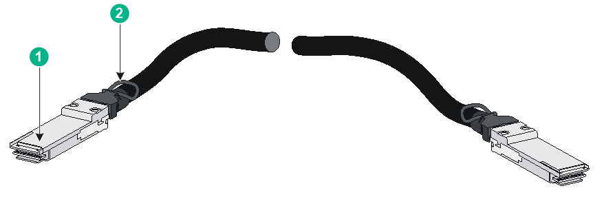
Figure4-3 40G QSFP+ cable
|
(1) Connector |
(2) Pull tab |
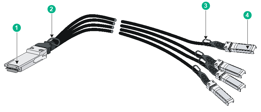
Figure4-4 40G QSFP+ to SFP+ cable
|
(1) QSFP+ module |
(2) QSFP+ side pull tab |
|
(3) SFP+ side pull tab |
(4) SFP+ module |
|
|
NOTE: · As a best practice, use H3C transceiver modules and cables for the switch. · You can use a QSFP-40G-SR4-MM850, QSFP-40G-CSR4-MM850, or QSFP-40G-LR4-PSM1310 transceiver module to connect a QSFP+ port to four SFP+ ports. The QSFP+ transceiver module and SFP+ transceiver modules to be connected must be the same in specifications, including central wavelength and fiber type. · The H3C transceiver modules and cables are subject to change over time. For the most recent list of H3C transceiver modules and cables, contact your H3C Support or marketing staff. · For more information about H3C transceiver modules and cables, see H3C Transceiver Modules User Guide. |
Combo interface
The S5560X-30C-EI and S5560X-30F-EI switches each provide eight combo interfaces. The S5560X-34S-EI switch provides four combo interfaces. A combo interface contains an SFP port and a 10/100/1000BASE-T autosensing Ethernet port. Only one of these two ports can operate at a time.
LEDs
System status LED
The system status LED shows the operating state of the switch.
Table4-18 System status LED description
|
LED mark |
Status |
Description |
|
SYS |
Steady green |
The switch is operating correctly. |
|
Flashing green (1 Hz) |
The switch is performing power-on self test (POST). |
|
|
Steady red |
The switch has failed the POST or is faulty. |
|
|
Off |
The switch is powered off. |
Power module status LED
The S5560X-EI switches except the S5560X-34S-EI and S5560X-54S-EI each provide two power module slots at the rear. For each power module, the switch provides a power module status LED on the front panel.
Table4-19 Power module status LED description
|
LED mark |
Status |
Description |
|
PWR1/PWR1 |
Steady green |
A power module is installed in the power module slot, and the power module is outputting power correctly. |
|
Steady yellow |
A power module is installed in the power module slot, but the power module has failed or no power is input to the power module. |
|
|
Off |
No power module is installed in the power module slot. |
AC/DC power input status LED
The S5560X-30F-EIF switch supports AC and DC power inputs and use an AC and a DC power input status LED to indicate the AC and DC power input status.
Table4-20 AC/DC power input status LED
|
LED mark |
Status |
Description |
|
AC PWR |
Steady green |
Normal AC input |
|
Off |
Abnormal or no AC input |
|
|
DC PWR |
Steady green |
Normal DC input |
|
Off |
Abnormal or no DC input |
RPS status LED
The S5560X-34S-EI and S5560X-54S-EI switches support RPS power input and use an RPS status LED to indicate the AC and DC power input status.
Table4-21 RPS status LED description
|
LED mark |
Status |
Description |
|
RPS |
Steady green |
Normal AC and DC input |
|
Steady yellow |
Normal DC input but abnormal or no AC input |
|
|
Off |
Abnormal or no DC input |
MODE LED
To show more information about the switch through the port status LEDs, the switch provides a MODE LED to indicate the type of information that the port status LEDs are showing.
You can use the mode button to change the indication of the MODE LED.
Table4-22 Description for the MODE LED
|
LED mark |
Status |
Description |
|
MODE |
Steady green |
The port status LEDs indicate port rates. |
|
Steady yellow |
The port status LEDs indicate the duplex mode of the ports. |
|
|
Flashing green (1 Hz) (available only for S5560X-30C-PWR-EI and S5560X-54C-PWR-EI switches) |
The port status LEDs indicate the PoE power supply status of the ports. |
|
|
Flashing yellow |
The port status LEDs indicates the IRF member ID of the switch. For example, if the LEDs for ports 1 to 5 are steady green and the other LEDs are off, the IRF member ID of the switch is 5. |
10/100/1000BASE-T autosensing Ethernet port LED
The switch provides a status LED for each 10/100/1000BASE-T autosensing Ethernet port. The port LED and the mode LED work in conjunction to indicate the operating status of the 10/100/1000BASE-T autosensing Ethernet port.
Table4-23 10/100/1000BASE-T autosensing Ethernet port LED description
|
Mode LED status |
10/100/1000BASE-T autosensing Ethernet port LED status |
Description |
|
Steady green (rate mode) |
Steady green |
A link is present on the port and the port is operating at 1000 Mbps. |
|
Flashing green |
The port is sending or receiving data at 1000 Mbps |
|
|
Steady yellow |
The port is operating at 10/100 Mbps. |
|
|
Flashing yellow |
The port is sending or receiving data at 10/100 Mbps |
|
|
Off |
No link is present on the port. |
|
|
Steady yellow (duplex mode) |
Steady green |
The port is operating at full-duplex mode and a link is present on the port. |
|
Flashing green |
The port is sending and receiving data at full-duplex mode. |
|
|
Steady yellow |
The port is operating at half-duplex mode and a link is present on the port. |
|
|
Flashing yellow |
The port is sending and receiving data at half-duplex mode. |
|
|
Off |
No link is present on the port. |
|
|
Flashing green (1 Hz) (PoE mode, available only for S5560X-30C-PWR-EI and S5560X-54C-PWR-EI switches) |
Steady green |
PoE power supply is normal. |
|
Flashing green (1 Hz) |
The device attached to the port requires power higher than the maximum or currently available PoE output power on the port. |
|
|
Steady yellow |
The port is experiencing a PoE failure. |
|
|
Off |
The port is not supplying power through PoE. |
|
|
Flashing yellow (IRF mode) |
· The S5560X-30C-EI, S5560X-54C-EI, S5560X-34S-EI, S5560X-54S-EI, S5560X-30C-PWR-EI, and S5560X-54C-PWR-EI switches use the 10/100/1000BASE-T autosensing Ethernet port LEDs to indicate the IRF member ID. For example, if the LEDs for ports 1 to 5 are steady green and the other port LEDs are off, the IRF member ID of the switch is 5. · An S5560X-30F-EI switch uses SFP port LEDs to indicate the IRF member ID. When the Mode LED is flashing yellow (IRF mode), the 10/100/1000BASE-T autosensing Ethernet port LEDs are off. |
|
SFP port LED
The SFP port LED and the mode LED work in conjunction to indicate the operating status of the SFP port.
Table4-24 SFP port LED description
|
Mode LED status |
SFP port LED status |
Description |
|
Steady green (rate mode) |
Steady green |
A link is present on the port and the port is operating at 1000 Mbps. |
|
Flashing green |
The port is sending or receiving data at 1000 Mbps. |
|
|
Steady yellow |
A link is present on the port and the port is operating at 100 Mbps. |
|
|
Flashing yellow |
The port is sending or receiving data at 100 Mbps. |
|
|
Off |
No link is present on the port. |
|
|
Steady yellow (duplex mode) |
Steady green |
The port is operating at full-duplex mode and a link is present on the port. |
|
Flashing green |
The port is sending and receiving data at full-duplex mode. |
|
|
Steady yellow |
The port is operating at half-duplex mode and a link is present on the port. |
|
|
Flashing yellow |
The port is sending and receiving data at half-duplex mode. |
|
|
Off |
No link is present on the port. |
|
|
Flashing yellow (IRF mode) |
· The S5560X-30F-EI, S5560X-30F-EIF, and S5560X-54F-EI switches use the SFP port LEDs to indicate the IRF member ID. For example, if the LEDs for ports 1 to 5 are steady green and the other port LEDs are off, the IRF member ID of the switch is 5. · The S5560X-30C-EI and S5560X-34S-EI switches use 10/100/1000BASE-T autosensing Ethernet port LEDs to indicate the IRF member ID. When the Mode LED is flashing yellow (IRF mode), the SFP port LEDs are off. |
|
SFP+ port LED
Table4-25 SFP+ port LED description
|
Mode LED status |
SFP+ port LED status |
Description |
|
Steady green (rate mode) |
Steady green |
A link is present on the port and the port is operating at 10 Gbps. |
|
Flashing green |
The port is sending or receiving data at 10 Gbps. |
|
|
Steady yellow |
A link is present on the port and the port is operating at 1 Gbps. |
|
|
Flashing yellow |
The port is sending or receiving data at 1 Gbps. |
|
|
Off |
No link is present on the port. |
|
|
Steady yellow (duplex mode) |
Steady green |
The port is operating at full-duplex mode and a link is present on the port. |
|
Flashing green |
The port is sending and receiving data at full-duplex mode. |
|
|
Steady yellow |
The port is operating at half-duplex mode and a link is present on the port. |
|
|
Flashing yellow |
The port is sending and receiving data at half-duplex mode. |
|
|
Off |
No link is present on the port. |
|
|
Flashing yellow (IRF mode) |
Off |
When the Mode LED is flashing yellow (IRF mode), the port LEDs are off. |
QSFP+ port LED
The S5560X-30F-EIF, S5560X-34S-EI, and S5560X-54S-EI switches each provide two QSFP+ ports on the rear panel.
Table4-26 QSFP+ port LED description
|
Mode LED status |
QSFP+ port LED status |
Description |
|
Steady green (rate mode) |
Steady green |
A link is present on the port and the port is operating at 40 Gbps. |
|
Flashing green |
The port is sending or receiving data at 40 Gbps. |
|
|
Steady yellow |
A link is present on the port and the port is operating at 10 Gbps. |
|
|
Flashing yellow |
The port is sending or receiving data at 10 Gbps. |
|
|
Off |
No link is present on the port. |
|
|
Steady yellow (duplex mode) |
Steady green |
The port is operating at full-duplex mode and a link is present on the port. |
|
Flashing green |
The port is sending and receiving data at full-duplex mode. |
|
|
Steady yellow |
The port is operating at half-duplex mode and a link is present on the port. |
|
|
Flashing yellow |
The port is sending and receiving data at half-duplex mode. |
|
|
Off |
No link is present on the port. |
|
|
Flashing yellow (IRF mode) |
Off |
When the Mode LED is flashing yellow (IRF mode), the port LEDs are off. |
Management Ethernet port LED
Table4-27 Management Ethernet port LED description
|
Management Ethernet port LED (ACT/LINK) status |
Description |
|
Steady green |
A link is present on the port. |
|
Flashing yellow |
The port is sending or receiving data. |
|
Off |
No link is present on the port. |
Expansion card status LED
The S5560X-EI switches except the S5560X-34S-EI and S5560X-54S-EI each provide an expansion slot at the rear. The expansion card status LED on the front panel indicates the operating state of the expansion card.
Table4-28 Expansion card status LED description
|
LED mark |
Status |
Description |
|
SLOT |
Steady green |
The expansion card is in position and is operating correctly. |
|
Flashing yellow |
The switch does not support the card model, or the card has failed. |
|
|
Off |
The expansion slot is empty. |
Port status LED on the expansion card
The expansion cards provide a port status LED for each port. For more information about the LEDs, see the manuals for the expansion cards.
Input status LED and output status LED on the power module
The PSR360-56A, PSR560-56D, PSR720-56A, and PSR1110-56A power modules each have an input status LED and an output status LED. For more information about the LEDs, see the manuals for the power modules.
Fan tray status LED on the fan tray
The LSPM1FANSA and LSPM1FANSB fan trays each have a fan tray status LED. The fan tray status LED on the fan tray indicates the operating state of the fan tray.
Table4-29 Fan tray status LED description
|
LED mark |
Status |
Description |
|
FAN |
Steady yellow |
The fan tray is operating correctly. |
|
Flashing yellow (1 Hz) |
The fan tray is faulty. |
|
|
Off |
The fan tray is not installed securely or has no power input. |
5 Cooling system
The switch uses a high-performance cooling system for fast heat dissipation and system stability. Consider the site ventilation design when you plan the installation site for the switch.
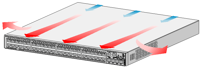
Some switch models use removable fan trays. You can choose fan tray models for these switches to provide airflow directions that match the heat dissipation requirements at the installation site. You must fully configure fan trays for these switches, and the fan trays on a switch must be the same model.
|
Device model |
Fan tray type and model |
Airflow direction |
|
S5560X-30C-EI S5560X-54C-EI S5560X-30F-EI S5560X-54F-EI S5560X-30C-PWR-EI S5560X-54C-PWR-EI |
Removable fan tray LSPM1FANSA |
From the power module side to the port side and side panels (S5560X-54C-EI switch as an example)
|
|
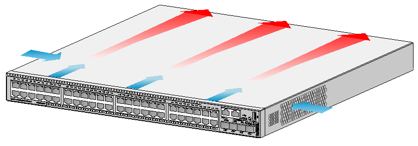
Removable fan tray LSPM1FANSB |
From the port side and side panels to the power module side (S5560X-54C-EI switch as an example)
|
|
|
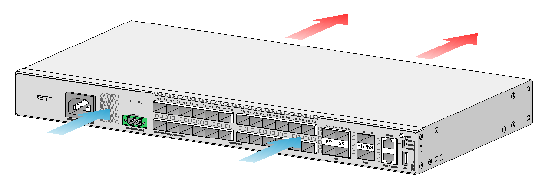
S5560X-30F-EIF |
Fixed fan tray |
From the port side to the grounding screw side (S5560X-30F-EIF switch as an example)
|
|
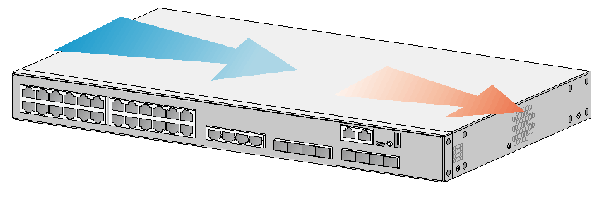
S5560X-34S-EI S5560X-54S-EI |
Fixed fan tray |
From the left side to the right side (face the port side of the device to identify the left and right sides) (S5560X-34S-EI switch as an example)
|