- Table of Contents
-
- 09-Security Configuration Guide
- 00-Preface
- 01-AAA configuration
- 02-802.1X configuration
- 03-MAC authentication configuration
- 04-Portal configuration
- 05-Web authentication configuration
- 06-Triple authentication configuration
- 07-Port security configuration
- 08-User profile configuration
- 09-Password control configuration
- 10-Keychain configuration
- 11-Public key management
- 12-PKI configuration
- 13-IPsec configuration
- 14-SSH configuration
- 15-SSL configuration
- 16-Attack detection and prevention configuration
- 17-TCP attack prevention configuration
- 18-IP source guard configuration
- 19-ARP attack protection configuration
- 20-ND attack defense configuration
- 21-uRPF configuration
- 22-SAVI configuration
- 23-MFF configuration
- 24-Crypto engine configuration
- 25-FIPS configuration
- 26-MACsec configuration
- 27-802.1X client configuration
- Related Documents
-
| Title | Size | Download |
|---|---|---|
| 20-ND attack defense configuration | 136.01 KB |
Contents
ND attack defense tasks at a glance
Enabling source MAC consistency check for ND messages
Configuring ND attack detection
Enabling ND detection on an interface
Enabling ND detection in a VLAN
Configuring ND attack detection for a VSI
Ignoring ingress ports of ND packets
Enabling ND attack detection logging
Display and maintenance commands for ND attack detection
Example: Configuring ND attack detection
Specifying the role of the attached device
Configuring and applying an RA guard policy
Enabling the RA guard logging feature
Display and maintenance commands for RA guard
Configuring ND attack defense
About ND attack defense
IPv6 Neighbor Discovery (ND) attack defense is able to identify forged ND messages to prevent ND attacks.
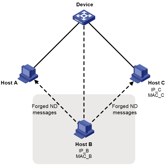
The IPv6 ND protocol does not provide any security mechanisms and is vulnerable to network attacks. As shown in Figure 1, an attacker can send the following forged ICMPv6 messages to perform ND attacks:
· Forged NS/NA/RS messages with an IPv6 address of a victim host. The gateway and other hosts update the ND entry for the victim with incorrect address information. As a result, all packets intended for the victim are sent to the attacking terminal.
· Forged RA messages with the IPv6 address of a victim gateway. As a result, all hosts attached to the victim gateway maintain incorrect IPv6 configuration parameters and ND entries.
ND attack defense tasks at a glance
All ND attack defense tasks are optional.
· Enabling source MAC consistency check for ND messages
· Configuring ND attack detection
Enabling source MAC consistency check for ND messages
About source MAC consistency check
The source MAC consistency check feature is typically configured on gateways to prevent ND attacks.
This feature checks the source MAC address and the source link-layer address for consistency for each arriving ND message.
· If the source MAC address and the source link-layer address are not the same, the device drops the packet.
· If the addresses are the same, the device continues learning ND entries.
The ND logging feature logs source MAC inconsistency events, and it sends the log messages to the information center. The information center can then output log messages from different source modules to different destinations. For more information about the information center, see Network Management and Monitoring Configuration Guide.
Procedure
1. Enter system view.
system-view
2. Enable source MAC consistency check for ND messages.
ipv6 nd mac-check enable
By default, source MAC consistency check is disabled for ND messages.
3. (Optional.) Enable the ND logging feature.
ipv6 nd check log enable
By default, the ND logging feature is disabled.
As a best practice, disable the ND logging feature to avoid excessive ND logs.
Configuring ND attack detection
About ND attack detection
ND attack detection checks incoming ND messages for user validity to prevent spoofing attacks. It is typically configured on access devices. It supports the following features:
· User validity check.
· ND attack detection for a VSI.
· ND attack detection logging.
ND attack detection defines the following types of interfaces:
· ND trusted interface—The device directly forwards ND messages or data packets received by ND trusted interfaces. It does not perform user validity check.
· ND untrusted interface—The device discards RA and redirect messages received by ND untrusted interfaces. For other types of ND messages received by the ND untrusted interfaces, the device checks the user validity.
ND attack detection compares the source IPv6 address and the source MAC address in an incoming ND message against security entries from other modules.
· If a match is found, the device verifies the user as legal in the receiving VLAN, and it forwards the packet.
· If no match is found, the device verifies the user as illegal, and it discards the ND message.
ND attack detection uses static IPv6 source guard binding entries, ND snooping entries, and DHCPv6 snooping entries for user validity check.
Static IPv6 source guard binding entries are created by using the ipv6 source binding command. For information about IPv6 source guard, see "Configuring IP source guard." For information about DHCPv6 snooping, see Layer 3–IP Services Configuration Guide. For information about ND snooping, see Layer 3–IP Services Configuration Guide.
Restrictions and guidelines
When you configure ND attack detection, follow these restrictions and guidelines:
· To prevent ND untrusted interfaces from dropping all received ND messages, make sure one or more of the these features are configured: IPv6 source guard static bindings, DHCPv6 snooping, and ND snooping.
· To make the IPv6 source guard static bindings effective for ND attack detection, you must perform the following operations:
¡ Specify the vlan vlan-id option in the ipv6 source binding command.
¡ Enable ND attack detection for the same VLAN.
· ND detection is enabled on an interface when you enable this feature on the interface or in the VLAN where the interface resides. To disable ND detection on an interface, disable this feature both on the interface and in the VLAN to which the interface belongs.
Enabling ND detection on an interface
1. Enter system view.
system-view
2. Enter interface view.
interface interface-type interface-number
3. Enable ND Detection.
ipv6 nd detection enable
By default, ND attack detection is disabled.
Enabling ND detection in a VLAN
1. Enter system view.
system-view
2. Enter VLAN view.
vlan vlan-id
3. Enable ND attack detection.
ipv6 nd detection enable
By default, ND attack detection is disabled.
4. (Optional.) Configure the interface as ND trusted interface:
a. Return to system view.
quit
b. Enter Layer 2 Ethernet or aggregate interface view.
interface interface-type interface-number
c. Configure the interface as ND trusted interface.
ipv6 nd detection trust
By default, all interfaces are ND untrusted interfaces.
Configuring ND attack detection for a VSI
About ND attack detection for a VSI
On a VXLAN network, you can configure user validity check for the associated VSI on the VTEP device. Different from the user validity check within a VLAN, which is performed on ND untrusted interfaces, the user validity check for a VSI is performed on ND untrusted ACs. The security entries used for user validity check and the check process are the same for a VLAN and a VSI.
Ethernet service instances that are associated with the VSI of a VXLAN are ACs. For more information, see VXLAN Configuration Guide.
Restrictions and guidelines
If both ND snooping and ND detection are enabled in a VSI, the device learns ND snooping entries only on the trusted ACs.
Procedure
1. Enter system view.
system-view
2. Enter VSI view.
vsi vsi-name
3. Enable ND attack detection.
ipv6 nd detection enable
By default, ND attack detection is disabled.
4. (Optional.) Configure the ND trusted AC.
a. Return to system view.
quit
b. Enter interface view.
interface interface-type interface-number
c. Enter Ethernet service instance view.
service-instance instance-id
d. (Optional.) Configure the AC as ND trusted AC.
ipv6 nd detection trust
By default, all ACs are ND untrusted ACs.
Ignoring ingress ports of ND packets
About this task
With ND attack detection enabled, the device can perform security check on received packets based on the local and remote IPSG bindings. Remote IPSG bindings do not contain port information. The device drops ND packets that match remote IPSG bindings because it does not find matching ingress ports for these packets. To prevent the device from dropping these packets, you can configure the device to ignore ingress ports of ND packets. This feature does not examine the ingress ports of ND packets, so that ND packets that match remote IPSG bindings will not be dropped.
Procedure
1. Enter system view.
system-view
2. Ignore ingress ports of ND packets in ND attack detection.
ipv6 nd detection port-match-ignore
By default, ingress ports of ND packets are examined in ND attack detection.
Enabling ND attack detection logging
About ND attack detection logging
This feature allows a device to generate logs when it detects invalid ND packets. The log information helps administrators locate and solve problems. Each log records the following information:
· Victim port numbers in a VLAN.
· Source IP address of the invalid ND packets.
· Source MAC address of the invalid ND packets.
· VLAN ID of the invalid ND packets.
· Total number of dropped ND packets.
Procedure
1. Enter system view.
system-view
2. Enable ND attack detection logging.
ipv6 nd detection log enable
By default, ND attack detection logging is disabled.
Display and maintenance commands for ND attack detection
Execute display commands in any view and reset commands in user view.
|
Task |
Command |
|
Display statistics for ND messages dropped by ND attack detection. |
display ipv6 nd detection statistics [ interface interface-type interface-number [ service-instance instance-id ] ] |
|
Clear ND attack detection statistics. |
reset ipv6 nd detection statistics [ interface interface-type interface-number [ service-instance instance-id ] ] |
Example: Configuring ND attack detection
Network configuration
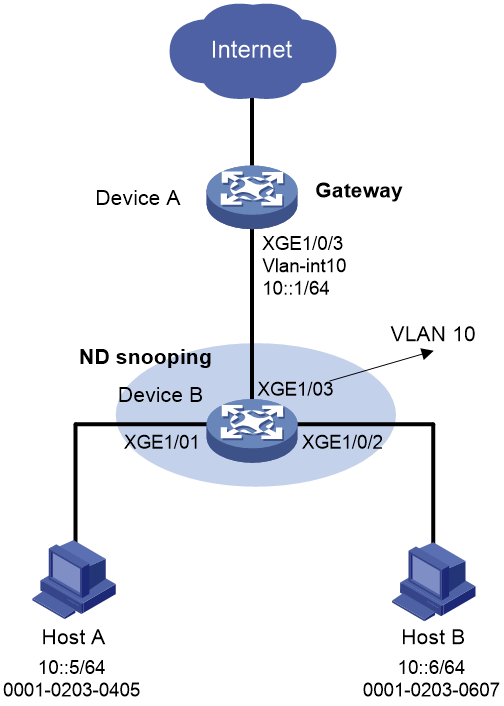
As shown in Figure 2, configure ND attack detection on Device B to check user validity for ND messages from Host A and Host B.
Procedure
# Create VLAN 10.
<DeviceA> system-view
[DeviceA] vlan 10
[DeviceA-vlan10] quit
# Configure Ten-GigabitEthernet 1/0/3 to trunk VLAN 10.
[DeviceA] interface ten-gigabitethernet 1/0/3
[DeviceA-Ten-GigabitEthernet1/0/3] port link-type trunk
[DeviceA-Ten-GigabitEthernet1/0/3] port trunk permit vlan 10
[DeviceA-Ten-GigabitEthernet1/0/3] quit
# Assign IPv6 address 10::1/64 to VLAN-interface 10.
[DeviceA] interface vlan-interface 10
[DeviceA-Vlan-interface10] ipv6 address 10::1/64
[DeviceA-Vlan-interface10] quit
2. Configure Device B:
# Create VLAN 10.
<DeviceB> system-view
[DeviceB] vlan 10
[DeviceB-vlan10] quit
# Configure Ten-GigabitEthernet 1/0/1, Ten-GigabitEthernet 1/0/2, and Ten-GigabitEthernet 1/0/3 to trunk VLAN 10.
[DeviceB] interface ten-gigabitethernet 1/0/1
[DeviceB-Ten-GigabitEthernet1/0/1] port link-type access
[DeviceB-Ten-GigabitEthernet1/0/1] port access vlan 10
[DeviceB-Ten-GigabitEthernet1/0/1] quit
[DeviceB] interface ten-gigabitethernet 1/0/2
[DeviceB-Ten-GigabitEthernet1/0/2] port link-type access
[DeviceB-Ten-GigabitEthernet1/0/2] port access vlan 10
[DeviceB-Ten-GigabitEthernet1/0/2] quit
[DeviceB] interface ten-gigabitethernet 1/0/3
[DeviceB-Ten-GigabitEthernet1/0/3] port link-type trunk
[DeviceB-Ten-GigabitEthernet1/0/3] port trunk permit vlan 10
[DeviceB-Ten-GigabitEthernet1/0/3] quit
# Enable ND attack detection for VLAN 10.
[DeviceB] vlan 10
[DeviceB-vlan10] ipv6 nd detection enable
# Enable ND snooping for IPv6 global unicast addresses and ND snooping for IPv6 link-local addresses in VLAN 10.
[DeviceB-vlan10] ipv6 nd snooping enable global
[DeviceB-vlan10] ipv6 nd snooping enable link-local
[DeviceB-vlan10] quit
# Configure Ten-GigabitEthernet 1/0/3 as ND trusted interface.
[DeviceB] interface ten-gigabitethernet 1/0/3
[DeviceB-Ten-GigabitEthernet1/0/3] ipv6 nd detection trust
Verifying the configuration
Verify that Device B inspects all ND messages received by Ten-GigabitEthernet 1/0/1 and Ten-GigabitEthernet 1/0/2 based on the ND snooping entries. (Details not shown.)
Configuring RA guard
About RA guard
RA guard allows Layer 2 access devices to analyze and block unwanted and forged RA messages.
Upon receiving an RA message, the device makes the forwarding or dropping decision based on the role of the attached device or the RA guard policy.
1. If the role of the device attached to the receiving interface is router, the device forwards the RA message. If the role is host, the device drops the RA message.
2. If no attached device role is set, the device uses the RA guard policy applied to the VLAN of the receiving interface to match the RA message.
¡ If the policy does not contain match criteria, the policy will not take effect and the device forwards the RA message.
¡ If the RA message content matches every criterion in the policy, the device forwards the message. Otherwise, the device drops the message.
Specifying the role of the attached device
Restrictions and guidelines
Make sure your setting is consistent with the type of the attached device. If you are not aware of the device type, do not specify a role for the device.
Procedure
1. Enter system view.
system-view
2. Enter interface view.
¡ Enter Layer 2 Ethernet interface view.
interface interface-type interface-number
¡ Enter aggregate interface view.
interface bridge-aggregation interface-number
3. Specify the role of the device attached to the interface.
ipv6 nd raguard role { host | router }
By default, the role of the device attached to the interface is not specified.
Configuring and applying an RA guard policy
About RA guard policy configuration
Configure an RA guard policy if you do not specify a role for the attached device or if you want to filter the RA messages sent by a router.
Procedure
1. Enter system view.
system-view
2. Create an RA guard policy and enter its view.
ipv6 nd raguard policy policy-name
3. Configure the RA guard policy.
Choose the following tasks as needed:
¡ Specify an ACL match criterion.
if-match acl { ipv6-acl-number | name ipv6-acl-name }
¡ Specify a prefix match criterion.
if-match prefix acl { ipv6-acl-number | name ipv6-acl-name }
¡ Specify a source MAC address match criterion.
if-match mac-address acl { acl-number | name acl-name }
¡ Specify a router preference match criterion.
if-match router-preference maximum { high | low | medium }
¡ Specify an M flag match criterion.
if-match autoconfig managed-address-flag { off | on }
¡ Specify an O flag match criterion.
if-match autoconfig other-flag { off | on }
¡ Specify a maximum or minimum hop limit match criterion.
if-match hop-limit { maximum | minimum } limit
By default, the RA guard policy is not configured.
4. Quit RA guard policy view.
quit
5. Enter VLAN view.
vlan vlan-number
6. Apply an RA guard policy to the VLAN.
ipv6 nd raguard apply policy [ policy-name ]
By default, no RA guard policy is applied to the VLAN.
Enabling the RA guard logging feature
About RA guard logging
This feature allows a device to generate logs when it detects forged RA messages. The log information helps administrators locate and solve problems. Each log records the following information:
· Name of the interface that received the forged RA message.
· Source IP address of the forged RA message.
· Number of RA messages dropped on the interface.
The RA guard logging feature sends the log messages to the information center. The information center can then output log messages from different source modules to different destinations. For more information about the information center, see Network Management and Monitoring Configuration Guide.
Procedure
1. Enter system view.
system-view
2. Enable the RA guard logging feature.
ipv6 nd raguard log enable
By default, the RA guard logging feature is disabled.
Display and maintenance commands for RA guard
Execute display commands in any view.
|
Task |
Command |
|
Display the RA guard policy configuration. |
display ipv6 nd raguard policy [ policy-name ] |
|
Display RA guard statistics. |
display ipv6 nd raguard statistics [ interface interface-type interface-number ] |
|
Clear RA guard statistics. |
reset ipv6 nd raguard statistics [ interface interface-type interface-number ] |
Example: Configuring RA guard
Network configuration
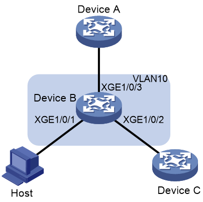
As shown in Figure 3, Ten-GigabitEthernet 1/0/1, Ten-GigabitEthernet 1/0/2, and Ten-GigabitEthernet 1/0/3 of Device B are in VLAN 10.
Configure RA guard on Device B to filter forged and unwanted RA messages.
· Configure an RA policy in VLAN 10 for Ten-GigabitEthernet 1/0/2 to filter all RA messages received from the unknown device.
· Specify host as the role of the host. All RA messages received on Ten-GigabitEthernet 1/0/1 are dropped.
· Specify router as the role of the Device A. All RA messages received on Ten-GigabitEthernet 1/0/3 are forwarded.
Procedure
# Create an RA guard policy named policy1.
<DeviceB> system-view
[DeviceB] ipv6 nd raguard policy policy1
# Set the maximum router preference to high for the RA guard policy.
[DeviceB-raguard-policy-policy1] if-match router-preference maximum high
# Specify on as the M flag match criterion for the RA guard policy.
[DeviceB-raguard-policy-policy1] if-match autoconfig managed-address-flag on
# Specify on as the O flag match criterion for the RA guard policy.
[DeviceB-raguard-policy-policy1] if-match autoconfig other-flag on
# Set the maximum advertised hop limit to 120 for the RA guard policy.
[DeviceB-raguard-policy-policy1] if-match hop-limit maximum 120
# Set the minimum advertised hop limit to 100 for the RA guard policy.
[DeviceB-raguard-policy-policy1] if-match hop-limit minimum 100
[DeviceB-raguard-policy-policy1] quit
# Assign Ten-GigabitEthernet 1/0/1 and Ten-GigabitEthernet 1/0/2 to VLAN 10.
[DeviceB] interface ten-gigabitethernet 1/0/1
[DeviceB-Ten-GigabitEthernet1/0/1] port link-type access
[DeviceB-Ten-GigabitEthernet1/0/1] port access vlan 10
[DeviceB-Ten-GigabitEthernet1/0/1] quit
[DeviceB] interface ten-gigabitethernet 1/0/2
[DeviceB-Ten-GigabitEthernet1/0/2] port link-type access
[DeviceB-Ten-GigabitEthernet1/0/2] port access vlan 10
[DeviceB-Ten-GigabitEthernet1/0/2] quit
# Configure Ten-GigabitEthernet 1/0/3 to trunk VLAN 10.
[DeviceB] interface ten-gigabitethernet 1/0/3
[DeviceB-Ten-GigabitEthernet1/0/3] port link-type trunk
[DeviceB-Ten-GigabitEthernet1/0/3] port trunk permit vlan 10
[DeviceB-Ten-GigabitEthernet1/0/3] quit
# Apply the RA guard policy policy1 to VLAN 10.
[DeviceB] vlan 10
[DeviceB-vlan10] ipv6 nd raguard apply policy policy1
[DeviceB-vlan10] quit
# Specify host as the role of the device attached to Ten-GigabitEthernet 1/0/1.
[DeviceB] interface ten-gigabitethernet 1/0/1
[DeviceB-Ten-GigabitEthernet1/0/1] ipv6 nd raguard role host
[DeviceB-Ten-GigabitEthernet1/0/1] quit
# Specify router as the role of the device attached to Ten-GigabitEthernet 1/0/3.
[DeviceB] interface ten-gigabitethernet 1/0/3
[DeviceB-Ten-GigabitEthernet1/0/3] ipv6 nd raguard role router
[DeviceB-Ten-GigabitEthernet1/0/3] quit
Verifying the configuration
# Verify that the device forwards or drops RA messages received on Ten-GigabitEthernet 1/0/2 based on the RA guard policy. (Details not shown.)
# Verify that the device drops RA messages received on Ten-GigabitEthernet 1/0/1. (Details not shown.)
# Verify that the device forwards RA messages received on Ten-GigabitEthernet 1/0/3 to other interfaces in VLAN 10. (Details not shown.)
