- Table of Contents
-
- 04-Layer 3-IP Services Configuration Guide
- 00-Preface
- 01-ARP configuration
- 02-IP addressing configuration
- 03-DHCP configuration
- 04-DNS configuration
- 05-mDNS relay configuration
- 06-IP forwarding basics configuration
- 07-Fast forwarding configuration
- 08-IRDP configuration
- 09-IP performance optimization configuration
- 10-Adjacency table configuration
- 11-UDP helper configuration
- 12-IPv6 basics configuration
- 13-DHCPv6 configuration
- 14-IPv6 fast forwarding configuration
- 15-GRE configuration
- 16-HTTP redirect configuration
- 17-Tunneling configuration
- Related Documents
-
| Title | Size | Download |
|---|---|---|
| 02-IP addressing configuration | 94.06 KB |
IP address representation and classes
Assigning an IP address to an interface
Display and maintenance commands for IP addressing
IP addressing configuration examples
Example: Manually specifying an IP address
Configuring IP addressing
About IP addressing
The IP addresses in this chapter refer to IPv4 addresses unless otherwise specified.
IP address representation and classes
IP addressing uses a 32-bit address to identify each host on an IPv4 network. To make addresses easier to read, they are written in dotted decimal notation, each address being four octets in length. For example, address 00001010000000010000000100000001 in binary is written as 10.1.1.1.
Each IP address breaks down into the following sections:
· Net ID—Identifies a network. The first several bits of a net ID, known as the class field or class bits, identify the class of the IP address.
· Host ID—Identifies a host on a network.
IP addresses are divided into five classes, as shown in Figure 1. The shaded areas represent the address class. The first three classes are most commonly used.
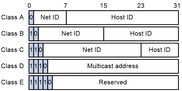
Table 1 IP address classes and ranges
|
Class |
Address range |
Remarks |
|
A |
0.0.0.0 to 127.255.255.255 |
The IP address 0.0.0.0 is used by a host at startup for temporary communication. This address is never a valid destination address. Addresses starting with 127 are reserved for loopback test. Packets destined to these addresses are processed locally as input packets rather than sent to the link. |
|
B |
128.0.0.0 to 191.255.255.255 |
N/A |
|
C |
192.0.0.0 to 223.255.255.255 |
N/A |
|
D |
224.0.0.0 to 239.255.255.255 |
Multicast addresses. |
|
E |
240.0.0.0 to 255.255.255.255 |
Reserved for future use, except for the broadcast address 255.255.255.255. |
Special IP addresses
The following IP addresses are for special use and cannot be used as host IP addresses:
· IP address with an all-zero net ID—Identifies a host on the local network. For example, IP address 0.0.0.16 indicates the host with a host ID of 16 on the local network.
· IP address with an all-zero host ID—Identifies a network.
· IP address with an all-one host ID—Identifies a directed broadcast address. For example, a packet with the destination address of 192.168.1.255 will be broadcast to all the hosts on the network 192.168.1.0.
Subnetting and masking
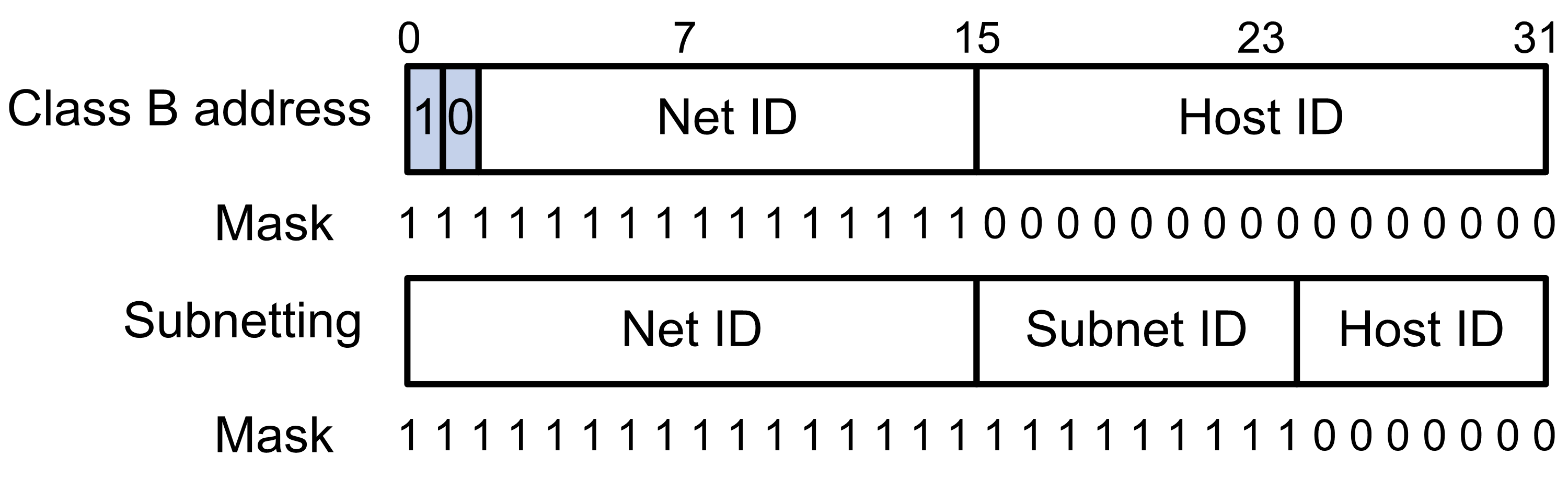
Subnetting divides a network into smaller networks called subnets by using some bits of the host ID to create a subnet ID.
Masking identifies the boundary between the host ID and the combination of net ID and subnet ID.
Each subnet mask comprises 32 bits that correspond to the bits in an IP address. In a subnet mask, consecutive ones represent the net ID and subnet ID, and consecutive zeros represent the host ID.
Before being subnetted, Class A, B, and C networks use these default masks (also called natural masks): 255.0.0.0, 255.255.0.0, and 255.255.255.0, respectively.
Figure 2 Subnetting a Class B network
Subnetting increases the number of addresses that cannot be assigned to hosts. Therefore, using subnets means accommodating fewer hosts.
For example, a Class B network without subnetting can accommodate 1022 more hosts than the same network subnetted into 512 subnets.
· Without subnetting—65534 (216 – 2) hosts. (The two deducted addresses are the broadcast address, which has an all-one host ID, and the network address, which has an all-zero host ID.)
· With subnetting—Using the first nine bits of the host-id for subnetting provides 512 (29) subnets. However, only seven bits remain available for the host ID. This allows 126 (27 – 2) hosts in each subnet, a total of 64512 (512 × 126) hosts.
IP address assignment
The following are methods available for assigning an IP address to an interface:
· Manual assignment. This chapter describes only manual IP address assignment for interfaces.
· BOOTP. For information about BOOTP, see "Configuring the BOOTP client."
· DHCP. For information about DHCP, see "Configuring the DHCP client."
These methods are mutually exclusive. If you change the IP address assignment method, the new IP address will overwrite the previous address.
Assigning an IP address to an interface
About manual IP address assignment
An interface can have one primary address and multiple secondary addresses.
Typically, you need to configure a primary IP address for an interface. If the interface connects to multiple subnets, configure primary and secondary IP addresses on the interface so the subnets can communicate with each other through the interface.
Restrictions and guidelines
· An interface can have only one primary IP address. If you execute the ip address command multiple times to specify different primary IP addresses on an interface, the most recent configuration takes effect.
· You cannot assign secondary IP addresses to an interface that obtains an IP address through IP unnumbered, BOOTP, or DHCP.
· The primary and secondary IP addresses assigned to the interface can be located on the same network segment. Different interfaces on your device must reside on different network segments.
· You can assign interfaces IP addresses that have different masks but the same network address if ANDed with the shortest mask. For example, 1.1.1.1/16 and 1.1.2.1/24 have the same network address 1.1.0.0 if ANDed with 255.255.0.0. You can assign the IP addresses to two interfaces on the device. By default, users connected to the two interfaces cannot communicate with each other. For the users to communicate, you must configure common proxy ARP on the device. For more information, see "Configuring proxy ARP."
Procedure
1. Enter system view.
system-view
2. Enter interface view.
interface interface-type interface-number
3. Assign an IP address to the interface.
ip address ip-address { mask-length | mask } [ sub ]
By default, no IP address is assigned to the interface.
Configuring IP unnumbered
About IP unnumbered
You can configure an interface to borrow an IP address from other interfaces. This is called IP unnumbered, and the interface borrowing the IP address is called IP unnumbered interface.
You can use IP unnumbered to save IP addresses when available IP addresses are inadequate or when an interface is used only occasionally.
Restrictions and guidelines
· Loopback interfaces cannot borrow IP addresses of other interfaces, but other interfaces can borrow IP addresses of loopback interfaces.
· An interface cannot borrow an IP address from an unnumbered interface.
· Multiple interfaces can use the same unnumbered IP address.
· If an interface has multiple manually configured IP addresses, only the manually configured primary IP address can be borrowed.
· A dynamic routing protocol cannot be enabled on the interface where IP unnumbered is configured. To enable the interface to communicate with other devices, configure a static route to the peer device on the interface.
· A Layer 3 Ethernet subinterface or Layer 3 aggregate subinterface cannot learn the ARP entry for the IP address it borrows. As a best practice, do not configure IP unnumbered on Layer 3 Ethernet subinterfaces or Layer 3 aggregate subinterfaces.
Prerequisites
Assign an IP address to the interface from which you want to borrow the IP address. Alternatively, you can configure the interface to obtain one through BOOTP, or DHCP.
Procedure
1. Enter system view.
system-view
2. Enter interface view.
interface interface-type interface-number
3. Specify the interface to borrow the IP address of the specified interface.
ip address unnumbered interface interface-type interface-number
By default, the interface does not borrow IP addresses from other interfaces.
Display and maintenance commands for IP addressing
Execute display commands in any view.
|
Task |
Command |
|
Display IP configuration and statistics for the specified or all Layer 3 interfaces. |
display ip interface [ interface-type [ interface-number ] ] |
|
Display brief IP configuration for Layer 3 interfaces. |
display ip interface [ interface-type [ interface-number ] ] brief [ description ] |
IP addressing configuration examples
Example: Manually specifying an IP address
Network configuration
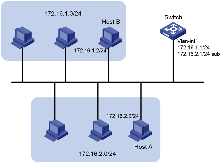
As shown in Figure 3, a port in VLAN 1 on a switch is connected to a LAN comprising two segments: 172.16.1.0/24 and 172.16.2.0/24.
To enable the hosts on the two network segments to communicate with the external network through the switch, and to enable the hosts on the LAN to communicate with each other:
· Assign a primary IP address and a secondary IP address to VLAN-interface 1 on the switch.
· Set the primary IP address of the switch as the gateway address of the PCs on subnet 172.16.1.0/24, and set the secondary IP address of the switch as the gateway address of the PCs on subnet 172.16.2.0/24.
Procedure
# Assign a primary IP address and a secondary IP address to VLAN-interface 1.
<Switch> system-view
[Switch] interface vlan-interface 1
[Switch-Vlan-interface1] ip address 172.16.1.1 255.255.255.0
[Switch-Vlan-interface1] ip address 172.16.2.1 255.255.255.0 sub
# Set the gateway address to 172.16.1.1 on the PCs attached to subnet 172.16.1.0/24, and to 172.16.2.1 on the PCs attached to subnet 172.16.2.0/24.
Verifying the configuration
# Verify the connectivity between a host on subnet 172.16.1.0/24 and the switch.
<Switch> ping 172.16.1.2
Ping 172.16.1.2 (172.16.1.2): 56 data bytes, press CTRL_C to break
56 bytes from 172.16.1.2: icmp_seq=0 ttl=128 time=7.000 ms
56 bytes from 172.16.1.2: icmp_seq=1 ttl=128 time=2.000 ms
56 bytes from 172.16.1.2: icmp_seq=2 ttl=128 time=1.000 ms
56 bytes from 172.16.1.2: icmp_seq=3 ttl=128 time=1.000 ms
56 bytes from 172.16.1.2: icmp_seq=4 ttl=128 time=2.000 ms
--- Ping statistics for 172.16.1.2 ---
5 packet(s) transmitted, 5 packet(s) received, 0.0% packet loss
round-trip min/avg/max/std-dev = 1.000/2.600/7.000/2.245 ms
# Verify the connectivity between a host on subnet 172.16.2.0/24 and the switch.
<Switch> ping 172.16.2.2
Ping 172.16.2.2 (172.16.2.2): 56 data bytes, press CTRL_C to break
56 bytes from 172.16.2.2: icmp_seq=0 ttl=128 time=2.000 ms
56 bytes from 172.16.2.2: icmp_seq=1 ttl=128 time=7.000 ms
56 bytes from 172.16.2.2: icmp_seq=2 ttl=128 time=1.000 ms
56 bytes from 172.16.2.2: icmp_seq=3 ttl=128 time=2.000 ms
56 bytes from 172.16.2.2: icmp_seq=4 ttl=128 time=1.000 ms
--- Ping statistics for 172.16.2.2 ---
5 packet(s) transmitted, 5 packet(s) received, 0.0% packet loss
round-trip min/avg/max/std-dev = 1.000/2.600/7.000/2.245 ms
# Verify the connectivity between a host on subnet 172.16.1.0/24 and a host on subnet 172.16.2.0/24. The ping operation succeeds.
